

Ricoh FAX2700L SPECIFICATIONS fx3700

FAX3700L
SERVICE MANUAL
September 21st, 1995
Subject to change
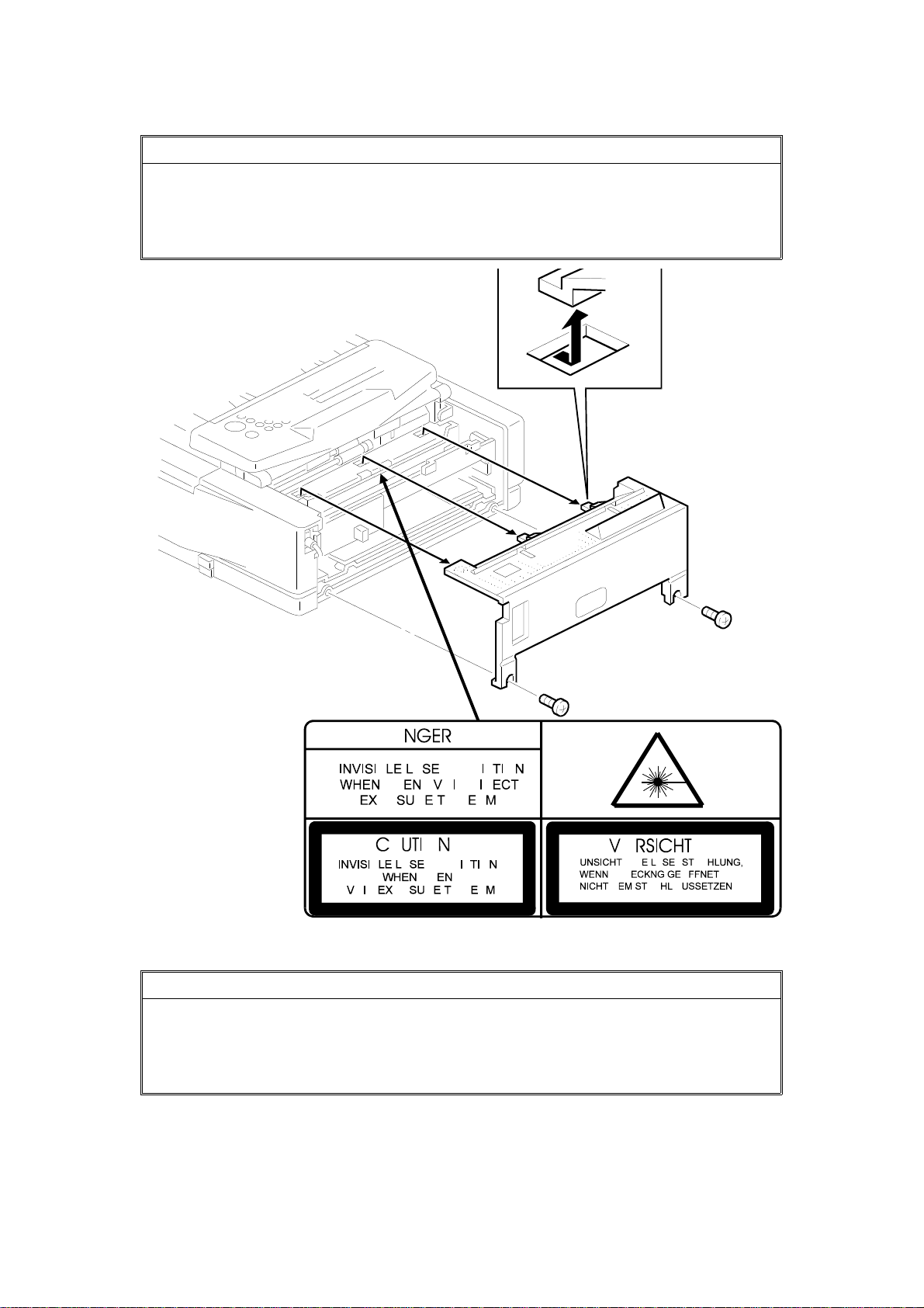
WARNING
I
THIS MACHINE CONTAINS A LASER BEAM G ENE RATOR. LASE R
BEAMS CAN CAUSE PERMANENT EYE DAMAGE. DO NOT OPEN THE
LASERUNIT OR LOOK ALONG THE LASER BEAM PATH WHILE THE
MAIN POWER IS ON.
Lithium Batteries (Memory Back-up)
CAUTION
I
The danger of explosion exists if a battery of this type is incorr ectly
replaced. Replace only with the same or an equival ent type
recommended by the manufac ture r. Discard used batteries in
accordance with the manufacturer’s instructions.

Table of Contents
1. OVERALL MACHINE INFORMATION
1.1. SPECIFICATIONS * . . . . . . . . . . . . . . . . . . 1-1
1.2. FEATURES * . . . . . . . . . . . . . . . . . . . . 1-3
1.3. COMPONENT LAYOUT . . . . . . . . . . . . . . . . 1-6
1.3.1. Mechanical Components . . . . . . . . . . . . . . 1-6
1.3.2. Drive Components . . . . . . . . . . . . . . . . 1-8
1.3.3. Electrical Components . . . . . . . . . . . . . . . 1-10
1. PCBs . . . . . . . . . . . . . . . . . . . . . . 1-11
2. Motors . . . . . . . . . . . . . . . . . . . . . . 1-11
3. Sensors . . . . . . . . . . . . . . . . . . . . . 1-12
4. Interlock Switches . . . . . . . . . . . . . . . . . 1-13
5. Others . . . . . . . . . . . . . . . . . . . . . . 1-13
6. Optional Equipment . . . . . . . . . . . . . . . . 1-14
1.4. OVERALL MACHINE CONTROL * . . . . . . . . . . . . 1-15
1.5. VIDEO DATA PATH . . . . . . . . . . . . . . . . . . 1-16
1.5.1. Transmission * . . . . . . . . . . . . . . . . . . 1-16
1.5.2. Reception * . . . . . . . . . . . . . . . . . . . 1-17
1.5.3. Copying . . . . . . . . . . . . . . . . . . . . 1-18
1.5.4. Printing from the Optional Printer Interface . . . . . . . 1-19
1.6. POWER DISTRIBUTION . . . . . . . . . . . . . . . . 1-20
1.6.1. Distribution Diagram * . . . . . . . . . . . . . . . 1-20
1.6.2. Memory Back-up Circuit . . . . . . . . . . . . . . 1-21
2. DETAILED SECTION DESCRIPTIONS
2.1. SCANNER . . . . . . . . . . . . . . . . . . . . . 2-1
2.1.1. Mechanisms . . . . . . . . . . . . . . . . . . . 2-1
1. Document Detection . . . . . . . . . . . . . . . . 2-1
2. Pick-up and Separation . . . . . . . . . . . . . . . 2-1
3. Drive Mechanism * . . . . . . . . . . . . . . . . . 2-2
4. Image Scanning * . . . . . . . . . . . . . . . . . 2-3
5. Sub Scan Resolution Conversion . . . . . . . . . . . 2-4
6. Stamping . . . . . . . . . . . . . . . . . . . . . 2-4
2.1.2. Scanner Timing Chart . . . . . . . . . . . . . . . 2-5
1. Timing Chart . . . . . . . . . . . . . . . . . . . 2-5
2. Jam Conditions . . . . . . . . . . . . . . . . . . 2-6
2.1.3. Video Processing . . . . . . . . . . . . . . . . . 2-7
1. Analog Signal Processing . . . . . . . . . . . . . . 2-7
2. Digital Video Processing Steps . . . . . . . . . . . . 2-8
3. Video Processing Parameters . . . . . . . . . . . . 2-11
2.2. PRINTING . . . . . . . . . . . . . . . . . . . . . . 2-12

2.2.1. Printing Process - Overview . . . . . . . . . . . . . 2-12
2.2.2. OPC Drum . . . . . . . . . . . . . . . . . . . . 2-13
2.2.3. Charge . . . . . . . . . . . . . . . . . . . . . 2-13
2.2.4. Laser Exposure . . . . . . . . . . . . . . . . . . 2-15
1. Overview . . . . . . . . . . . . . . . . . . . . . 2-15
2. Block Diagram . . . . . . . . . . . . . . . . . . 2-16
3. Error Conditions . . . . . . . . . . . . . . . . . . 2-16
4. Print Density Adjustment . . . . . . . . . . . . . . . 2-17
5. Toner Saving Mode . . . . . . . . . . . . . . . . . 2-17
2.2.5. Toner Supply . . . . . . . . . . . . . . . . . . . 2-18
2.2.6. Development . . . . . . . . . . . . . . . . . . . 2-21
2.2.7. Paper Feed . . . . . . . . . . . . . . . . . . . 2-26
1. Overview * . . . . . . . . . . . . . . . . . . . . 2-26
2. Paper Lift Mechanism . . . . . . . . . . . . . . . . 2-27
3. Paper Size and Paper End Detection . . . . . . . . . . 2-28
4. Pick-up and Separation . . . . . . . . . . . . . . . 2-30
5. Drive Mechanism . . . . . . . . . . . . . . . . . 2-30
2.2.8. Registration . . . . . . . . . . . . . . . . . . . 2-33
2.2.9. Transfer and Separation . . . . . . . . . . . . . . 2-35
2.2.10. Cleaning . . . . . . . . . . . . . . . . . . . . 2-38
2.2.11. Fusing . . . . . . . . . . . . . . . . . . . . . 2-39
2.2.12. Page Separation and Data Reduction . . . . . . . . 2-43
2.2.13. Paper Size Selection * . . . . . . . . . . . . . . 2-45
2.3. SYSTEM FEATURES . . . . . . . . . . . . . . . . . 2-46
2.3.1. Power Saver Modes * . . . . . . . . . . . . . . . 2-46
1. Going into a Power Saver Mode . . . . . . . . . . . . 2-47
2. Going into Level 2 Mode from Level 1 Mode * . . . . . . 2-49
3. Receiving a Fax Message in Power Saver Mode . . . . . 2-51
4. Sending a Fax Message or Copying in Power Saver Mode . 2-53
2.3.2. Automatic Service Calls . . . . . . . . . . . . . . 2-55
1. Service Call Conditions . . . . . . . . . . . . . . . 2-55
2. Excessive Jam Alarms . . . . . . . . . . . . . . . 2-56
3. Periodic Service Call . . . . . . . . . . . . . . . . 2-57
4. PM Call . . . . . . . . . . . . . . . . . . . . . 2-58
5. Effective Term of Service Calls . . . . . . . . . . . . 2-58
2.4. PCBs . . . . . . . . . . . . . . . . . . . . . . . 2-59
2.4.1. FCE2 * . . . . . . . . . . . . . . . . . . . . . 2-59
1. FCIP (Facsimile Controller and Image Processor) . . . . . 2-59
2. Modem (Rockwell R144EFXL) * . . . . . . . . . . . . 2-59
3. ROM * . . . . . . . . . . . . . . . . . . . . . . 2-60
4. DRAM * . . . . . . . . . . . . . . . . . . . . . 2-60
5. SRAM . . . . . . . . . . . . . . . . . . . . . . 2-60
6. Video SRAM . . . . . . . . . . . . . . . . . . . 2-60
7. Oscillators * . . . . . . . . . . . . . . . . . . . . 2-60

8. Jumpers, Switches, and Test Points . . . . . . . . . . . . . . . . . . . . . . . . . 2-60
2.4.2. FDU * . . . . . . . . . . . . . . . . . . . . . . 2-61
1. Power Saver CPU . . . . . . . . . . . . . . . . . 2-61
2. FPD (Facsimile Power Driver) . . . . . . . . . . . . 2-61
3. EXIO (External I/O) * . . . . . . . . . . . . . . . . 2-61
4. HIC (Hybrid IC) . . . . . . . . . . . . . . . . . . 2-61
5. DC/DC Converters . . . . . . . . . . . . . . . . . 2-61
6. Interlock Switches . . . . . . . . . . . . . . . . . 2-62
7. Jumpers, Switches, and Test Points . . . . . . . . . . 2-62
2.4.3. PSU . . . . . . . . . . . . . . . . . . . . . . 2-62
2.4.4. NCU (USA) . . . . . . . . . . . . . . . . . . . 2-63
1. Jumpers . . . . . . . . . . . . . . . . . . . . . 2-63
2.4.5. NCU (Europe/Asia) . . . . . . . . . . . . . . . . 2-64
1. Control Signals and Jumpers . . . . . . . . . . . . . 2-64
3. INSTALLATION
3.1. INSTALLING THE MACHINE . . . . . . . . . . . . . . 3-1
3.2. INITIAL PROGRAMMING . . . . . . . . . . . . . . . 3-1
3.3. INSTALLING OPTIONAL UNITS . . . . . . . . . . . . . 3-2
3.3.1. Printer Interface . . . . . . . . . . . . . . . . . . 3-2
3.3.2. Counter . . . . . . . . . . . . . . . . . . . . . 3-3
3.3.3. Handset . . . . . . . . . . . . . . . . . . . . . 3-3
3.3.4. RS232C Interface . . . . . . . . . . . . . . . . . 3-4
4. SERVICE TABLES AND PROCEDURES
4.1. SERVICE LEVEL FUNCTIONS . . . . . . . . . . . . . 4-1
4.1.1. Bit Switch Programming (Function 01) . . . . . . . . . 4-1
4.1.2. System Parameter List (Function 02) . . . . . . . . . 4-2
4.1.3. Error Code Display (Function 03) . . . . . . . . . . . 4-3
4.1.4. Service Monitor Report (Function 04) . . . . . . . . . 4-3
4.1.5. Protocol Dump (Function 05) . . . . . . . . . . . . 4-4
4.1.6. RAM Display/Rewrite (Function 06) . . . . . . . . . . 4-4
4.1.7. RAM Dump (Function 06) . . . . . . . . . . . . . . 4-5
4.1.8. Counter Display/Rewrite (Function 07) . . . . . . . . . 4-5
4.1.9. NCU Parameters (Function 08) . . . . . . . . . . . . 4-6
4.1.10. Modem Test (Function 08) . . . . . . . . . . . . . 4-7
4.1.11. DTMF Tone Test (Function 08) . . . . . . . . . . . 4-7
4.1.12. Modem Detection Test (Function 08) . . . . . . . . . 4-8
4.1.13. Ringer Test (Function 08) . . . . . . . . . . . . . 4-8
4.1.14. Operation Panel Test (Function 09) . . . . . . . . . 4-9
4.1.15. LED Array Test (Function 10) . . . . . . . . . . . . 4-9
4.1.16. ADF Test (Function 10) . . . . . . . . . . . . . . 4-10
4.1.17. Printer Test Patterns (Function 11) . . . . . . . . . . 4-10

4.1.18. Printer Mechanism Test - Free Run (Function 11) . . . . 4-11
4.1.19. RAM Tests (Function 12) . . . . . . . . . . . . . . 4-11
4.1.20. Software Download (Function 12) . . . . . . . . . . 4-12
4.1.21. Software Upload (Function 12) . . . . . . . . . . . 4-13
4.1.22. SRAM Data Download (Function 12) . . . . . . . . . 4-14
4.1.23. Serial Number (Function 14) . . . . . . . . . . . . 4-15
4.1.24. Service Station Fax Number (Function 13) . . . . . . . 4-15
4.2. BIT SWITCHES . . . . . . . . . . . . . . . . . . . 4-16
4.2.1. System Switches . . . . . . . . . . . . . . . . . 4-16
4.2.2. Scanner Switches . . . . . . . . . . . . . . . . 4-25
4.2.3. Printer Switches . . . . . . . . . . . . . . . . . 4-27
4.2.4. Communication Switches . . . . . . . . . . . . . . 4-30
4.2.5. G3 Switches . . . . . . . . . . . . . . . . . . . 4-36
4.3. NCU PARAMETERS * . . . . . . . . . . . . . . . . . 4-42
4.4. DEDICATED TRANSMISSION PARAMETERS . . . . . . . 4-70
4.4.1. Programming Procedure . . . . . . . . . . . . . . 4-70
4.4.2. Parameters . . . . . . . . . . . . . . . . . . . 4-71
4.5. SERVICE RAM ADDRESSES * . . . . . . . . . . . . . 4-73
4.6. SPECIAL TOOLS AND LUBRICANTS . . . . . . . . . . 4-86
4.7. PM TABLE . . . . . . . . . . . . . . . . . . . . . 4-86
5. REPLACEMENT AND ADJUSTMENT
5.1. COVERS . . . . . . . . . . . . . . . . . . . . . . 5-1
5.1.1. Document Table and Tray . . . . . . . . . . . . . . 5-1
5.1.2. Rear Cover Assembly . . . . . . . . . . . . . . . 5-2
5.1.3. Left Cover . . . . . . . . . . . . . . . . . . . . 5-2
5.1.4. Right Cover . . . . . . . . . . . . . . . . . . . 5-3
5.1.5. Operation Panel Assembly . . . . . . . . . . . . . 5-3
5.1.6. Operation Panel and ADF Upper Unit . . . . . . . . . 5-4
5.1.7. Top Cover . . . . . . . . . . . . . . . . . . . . 5-4
5.2. OPERATION PANEL . . . . . . . . . . . . . . . . . 5-5
5.2.1. Operation Panel and OPU . . . . . . . . . . . . . 5-5
5.3. ADF . . . . . . . . . . . . . . . . . . . . . . . . 5-5
5.3.1. ADF Roller Assembly . . . . . . . . . . . . . . . . 5-5
5.3.2. Separation Rubber Plate . . . . . . . . . . . . . . 5-6
5.3.3. Separation Pressure Adjustment . . . . . . . . . . . 5-6
5.3.4. ADF Sensors . . . . . . . . . . . . . . . . . . . 5-7
5.3.5. Scanner Shading Plate . . . . . . . . . . . . . . . 5-7
5.4. SCANNER . . . . . . . . . . . . . . . . . . . . . 5-8
5.4.1. Scanner Unit Disassembly . . . . . . . . . . . . . 5-8
5.4.2. Tx Motor and Drive Components . . . . . . . . . . . 5-8
5.4.3. R1/R2 Rollers . . . . . . . . . . . . . . . . . . 5-9
5.4.4. Contact Image Sensor . . . . . . . . . . . . . . . 5-10
5.5. LASER PRINTING COMPONENTS . . . . . . . . . . . 5-11
5.5.1. Laser Unit . . . . . . . . . . . . . . . . . . . . 5-11

5.5.2. Laser Diode Unit and Hexagonal Mirror Motor . . . . . . 5-12
5.6. DEVELOPMENT . . . . . . . . . . . . . . . . . . . 5-13
5.6.1. Development Unit . . . . . . . . . . . . . . . . . 5-13
5.6.2. Transfer Roller . . . . . . . . . . . . . . . . . . 5-14
5.6.3. Main Motor and Gears . . . . . . . . . . . . . . . 5-14
5.6.4. Replacing the Development Unit . . . . . . . . . . . 5-15
5.7. FUSING . . . . . . . . . . . . . . . . . . . . . . 5-18
5.7.1. Thermistor . . . . . . . . . . . . . . . . . . . . 5-18
5.7.2. Fusing Unit . . . . . . . . . . . . . . . . . . . 5-18
5.7.3. Hot Roller Strippers . . . . . . . . . . . . . . . . 5-20
5.7.4. Fusing Lamp . . . . . . . . . . . . . . . . . . . 5-20
5.7.5. Hot Roller . . . . . . . . . . . . . . . . . . . . 5-21
5.7.6. Pressure Roller . . . . . . . . . . . . . . . . . . 5-23
5.7.7. Thermostat and Thermofuse . . . . . . . . . . . . . 5-23
5.8. PAPER FEED . . . . . . . . . . . . . . . . . . . . 5-24
5.8.1. Paper Feed Motor and Clutch Box . . . . . . . . . . 5-24
5.8.2. Paper End Sensor . . . . . . . . . . . . . . . . . 5-24
5.8.3. Paper Feed Rollers, Paper Size Sensor, and Relay Connector 5-25
5.8.4. Registration Roller and Bypass Feed Sensor . . . . . . 5-26
5.9. PCBs . . . . . . . . . . . . . . . . . . . . . . . 5-27
5.9.1. PSU and NCU . . . . . . . . . . . . . . . . . . 5-27
5.9.2. NCU, FDU, and FCE . . . . . . . . . . . . . . . . 5-27
5.9.3. Power Pack . . . . . . . . . . . . . . . . . . . 5-28
5.10. OTHERS . . . . . . . . . . . . . . . . . . . . . . 5-29
5.10.1. Ozone Filter and Fan Motor . . . . . . . . . . . . 5-29
5.11. 100 SHEET PAPER CASSETTE (OPTIONAL) . . . . . . . 5-29
5.11.1. Relay Connector and Gear Cover . . . . . . . . . . 5-29
5.11.2. Paper End Sensor and Drive Components . . . . . . . 5-30
5.11.3. Paper Size Sensor . . . . . . . . . . . . . . . . 5-31
5.12. IMAGE ADJUSTMENT . . . . . . . . . . . . . . . . 5-32
5.12.1. Overview . . . . . . . . . . . . . . . . . . . . 5-32
5.12.2. Scanner Parameters . . . . . . . . . . . . . . . 5-33
1. Contrast . . . . . . . . . . . . . . . . . . . . . 5-33
2. Margins . . . . . . . . . . . . . . . . . . . . . 5-33
5.12.3. Printer Parameters . . . . . . . . . . . . . . . . 5-34
1. Margins (Main Scan Direction) * . . . . . . . . . . . . 5-34
2. Margins (Sub Scan Direction) * . . . . . . . . . . . . 5-35
6. TROUBLESHOOTING
6.1. COPY QUALITY TROUBLESHOOTING . . . . . . . . . . 6-1
6.1.1. Blank Copies . . . . . . . . . . . . . . . . . . . 6-2
6.1.2. Black Copies . . . . . . . . . . . . . . . . . . . 6-3
6.1.3. Dirty Background . . . . . . . . . . . . . . . . . 6-4
6.1.4. Uneven Image Density . . . . . . . . . . . . . . . 6-5
6.1.5. Vertical Black Lines . . . . . . . . . . . . . . . . 6-6

6.1.6. Horizontal Black Lines . . . . . . . . . . . . . . . 6-7
6.1.7. Vertical White Lines . . . . . . . . . . . . . . . . 6-8
6.1.8. Horizontal White Lines . . . . . . . . . . . . . . . 6-9
6.1.9. Black Dots/Spots . . . . . . . . . . . . . . . . . 6-10
6.1.10. White Spots in Black Image Areas . . . . . . . . . . 6-11
6.1.11. Faint Copies . . . . . . . . . . . . . . . . . . 6-12
6.1.12. Vertical Black Band . . . . . . . . . . . . . . . . 6-14
6.1.13. Unfused Copies . . . . . . . . . . . . . . . . . 6-15
6.1.14. Ghost Image . . . . . . . . . . . . . . . . . . 6-15
6.1.15. Toner on the Back of the Printer Paper . . . . . . . . 6-16
6.1.16. Misaligned Output (Data shifted to the right or left) . . . 6-17
6.1.17. Misaligned Output (Image shifted vertically)/Reduced Image 6-17
6.2. MECHANICAL PROBLEMS . . . . . . . . . . . . . . 6-18
6.2.1. ADF/Scanner . . . . . . . . . . . . . . . . . . . 6-18
1. Non Feed . . . . . . . . . . . . . . . . . . . . 6-18
2. Jam . . . . . . . . . . . . . . . . . . . . . . . 6-19
3. Skew . . . . . . . . . . . . . . . . . . . . . . 6-20
4. Multi-feed . . . . . . . . . . . . . . . . . . . . 6-20
6.2.2. Printer . . . . . . . . . . . . . . . . . . . . . 6-21
1. Non-feed . . . . . . . . . . . . . . . . . . . . . 6-21
2. Paper Jam - Inside Printer . . . . . . . . . . . . . . 6-22
3. Jam - Fusing Exit . . . . . . . . . . . . . . . . . 6-23
4. Skew . . . . . . . . . . . . . . . . . . . . . . 6-24
5. Multi-feed . . . . . . . . . . . . . . . . . . . . 6-25
6.3. SERVICE CALL CONDITIONS . . . . . . . . . . . . . 6-26
6.4. ERROR CODES . . . . . . . . . . . . . . . . . . . 6-30
6.5. ELECTRICAL COMPONENT DEFECTS . . . . . . . . . 6-37
6.5.1. Defective Sensor Table . . . . . . . . . . . . . . . 6-37
6.5.2. Blown Fuse Table . . . . . . . . . . . . . . . . . 6-37

August 2nd, 1995 OVERALL MACHINE INFORMATION
SPECIFICATIONS *
1. OVERALL MACHINE INFORMATION
1.1. SPECIFICATIONS *
Type
Desktop type transceiver
Circuit
PSTN, PABX
Connection
Direct couple
Document Size
Length:
105 - 420 mm [4.1 - 16.5 ins]
Up to 1.2 m [47.2 ins], manually assisted
Up to 14 m [46 ft] after adjustment
Width:
148 - 304 mm [5.8 - 12.0 ins]
Thickness:
0.05 to 0.2 mm [2 to 8 mils]
(equivalent to 50 - 80 g/m
Document Feed
Automatic feed, face down
ADF Capacity
30 sheets (using 20 lb or 80 g/m
Scanning Method
Contact image sensor
Maximum Scan Width
256 mm [10.1 ins] ± 0.25%
Scan Resolutions
Main scan: 8 dots/mm [203 dpi]
Sub scan:
Standard - 3.85 lines/mm [98 lpi]
Detail - 7.7 lines/mm [196 lpi]
Fine - 15.4 lines/mm [392 lpi]
Memory Capacity
ECM: 64 or 128 kbytes
(depends on the amount of image data)
SAF: 512 kbytes (38 pages/Slerexe letter),
extra 2 Mbyte (186 pages) or 4 Mbyte (350
pages) memory card available
Compression
MH, MR, EFC, MMR, SSC (MMR only with
ECM)
SAF storage for memory tx: MMR and raw
data
2
)
2
paper)
Protocol
Group 3 with ECM
Modulation
V.33/ V.17(TCM), V.29 (QAM), V.27ter
(PHM), V.21 (FM)
Data Rate (bps)
14,400/12,000/9600/7200/4800/2400
Automatic fallback
I/O Rate
With ECM: 0 ms/line
Without ECM: 2.5, 5, 10, 20, or 40 ms/line
Transmission Time
6 s at 14,400 bps; Measured with G3 ECM
using memory for a ITU-T #1 test document
(Slerexe letter) at standard resolution
Printing System
Laser printing, plain paper, dry toner
Paper Size and Capacity
Standard Cassette: 250 sheets
USA: Letter, Legal
Europe: A4, A5 sideways
Asia: A4, A5 sideways, F, F4
100 Sheet Cassette (Optional): 100 sheets
USA: Letter, Legal
Europe: A4, A5 sideways
Asia: A4, A5 sideways, F, F4
Paper Feed Unit (Optional): 500 sheets
USA: Letter, Legal
Europe: A4, A5 sideways
Asia: A4, A5 sideways, F/F4
Maximum Printing Width
208 mm [8.1 ins]
Print Resolutions
Fax and Copy Mode:
Main scan: 16 dots per mm [406 dpi]
Sub scan: 15.4 lines/mm [392 lpi]
Printer Mode: 300 x 300 dpi
Power Supply
USA: 115 ± 20 Vac, 60 ± 1 Hz
Europe/Asia: 187 - 276 Vac, 50 ± 3 Hz
Power Consumption (Base Machine Only)
Standby: Minimum 2 W; Normal 20 W
Transmit: 25 W
Receive: 210 W
Copying: 270 W
1-1

OVERALL MACHINE INFORMATION August 2nd, 1995
SPECIFICATIONS *
Operating Environment
Temperature: 17 - 28 °C [63 - 82 °F]
Humidity: 40 - 70 %Rh
Dimensions (W x D x H)
475 x 459 x 240 mm [18.7 x 18.1 x 9.4 ins]
Excluding handset, trays, and optional units
Weight
Approx. 17 kg [37 lbs]
Excluding CTM, handset, trays, and optional
units
1-2
August 2nd, 1995 OVERALL MACHINE INFORMATION
FEATURES *
1.2. FEATURES *
KEY: O = Used, X = Not Used,
A = With optional memory only,
B = With optional 100 sheet cassette only
C = With optional counter only
D = With optional handset only
E = With optional printer interface only
F = With optional paper feed unit only
Equipment
ADF O
Book scan X
Built-in handset X
Bypass feed: 1 sheet O
Optional cassette: 100 sheets B
Optional cassette: Universal O
Optional paper feed unit F
Cabinet X
Mechanical Counter C
Cutter X
Handset D
Hard disk X
Manual feed mechanism X
Marker (Stamp) O
Monitor speaker O
Optional printer interface E
Video Processing Features
Contrast O
Halftone (Basic & Error Diffusion) O
MTF O
Reduction (B4 -> A4) O
Resolution O
Smoothing to 16 x 15.4 l/mm O
Communication Features - Auto
Automatic fallback O
Automatic redialing O
Confidential reception A
Dual Access O
Substitute reception O
Communication Features -
User Selectable
Action as a transfer broadcaster X
AI Redial (last ten numbers) O
Answering machine interface X
Communication Features -
User Selectable
Authorized Reception O
Auto-answer delay time X
Auto dialing (pulse or DTMF) O
Auto Document O
Auto image density selection X
Auto paper size selection X
Automatic Voice Message X
Batch Transmission (max 6 files) A
Broadcasting O
Chain Dialing O
Communication Result Display X
Confidential ID Override O
Confidential Transmission O
Direct Fax Number Entry O
Economy T rans miss ion X
Fax on demand X
Forwarding A
Free Polling O
Groups (7 groups) O
Group Transfer Station X
Hold X
ID Transmission O
Immediate Redialing O
Immediate transmission O
Keystroke Programs O
Memory transmission O
Multi-step Transfer X
Next Transfer Station X
OMR X
On Hook Dial O
Ordering Toner X
Page Count O
Personal Codes O
Personal Codes with Conf. ID A
Polling Reception O
Polling Transmission O
Polling tx file lifetime in the SAF O
Quick Dial (32 stations) O
Reception modes (Fax, Tel,
Length Reduction O
Remote control features X
Remote Transf er X
Restricted Access O
Secured Polling O
Auto) O
1-3
OVERALL MACHINE INFORMATION August 2nd, 1995
FEATURES *
Communication Features -
User Selectable
Secured Polling with Stored ID
Override
Secure Transmission X
Send Later O
Silent ringing detection X
Specified Image Area X
Speed Dial (90 stations) O
Super Fine Resolution
(16 x15.4 l/mm : 400 x 400 dpi)
Telephone Directory O
Tonal Signal Transmission O
Transfer Request O
Transmission Deadline (TRD) A
Turnaround Polling X
Two- step Transfer X
Two in one O
Voice Request (immed. tx only) X
Communication Features -
Service Selectable
AI Short Protocol O
Auto-reduction override option O
Busy tone detection O
Closed Network (tx and rx) O
Continuous Polling Reception O
Dedicated tx parameters O
ECM O
EFC O
Inch-mm conversion X
Page retransmission times O
Page separation mark O
Protection against wrong conn. O
Resol’n stepdown override option X
Short Preamble X
Well log O
Other User Features
Area code prefix X
Automatic service call Service
Center mark O
Checkered mark O
Clearing a memory file O
Clearing a polling file O
Clock O
Confidential ID A
O
X
Other User Features
Copy editing (Erase Center/Margin)
Copy mode O
Copy Mode Restriction X
Counters O
Daylight Saving Time O
Destination Check X
Direct entry of names O
File Retention Time X
File Retransmission X
Function Programs O
ID Code O
Label Insertion ("From xxx") O
Language Selection O
LCD contrast control Service
Memory Lock A
Memory Lock ID A
Modifying a memory file X
Multi Sort Document Reception A
Multicopy mode O
Own telephone number O
Power Saver (Night Timer and
standby mode)
Print density control O
Printing a memory file O
RDS on/off O
Reception Mode Switching Timer X
Reception time printing O
Reduction/Enlargement X
Remaining memory indicator O
Remote ID X
Reverse Order Printing A
RTI, TTI, CSI O
Secure ID X
Service Report Transmission O
Speaker volume control O
Specified Cassette Selection B
Substitute reception on/off O
Telephone line type O
Toner Saving Mode O
TTI on/off O
User Function Keys X
User Parameters O
Wild Cards O
X
O
1-4
August 2nd, 1995 OVERALL MACHINE INFORMATION
FEATURES *
Reports - Automat ic
Charge Control Report X
Communication Failure Report O
Confidential File Report A
Error Report O
Memory Storage Report O
Mode Change Report X
Polling Clear Report O
Polling Reserve Report O
Polling Result Report O
Power Failure Report O
TCR (Journal) O
Toner Cassette Order Form X
Transfer Result Report X
Transmission Result Report O
Reports - User-initiated
Authorized Reception List O
Charge Control Report X
File List O
Forwarding List A
Group List O
Personal Code List O
Program List O
Quick Dial List O
Specified Cassette Selection List B
Speed Dial List O
TCR O
Transmission Status Report X
User Function List X
User Parameter List O
Service Mode Features
File Transfer O
LCD contrast adjustment O
Line error mark O
Memory file printout (all files) O
Modem test O
NCU parameters O
Operation panel test O
Periodic service call O
PM Call O
Printer mechanism test O
Printer test patterns O
Programmable attenuation X
Protocol dump list O
RAM display/rewrite O
RAM dump O
RAM test O
Ringer test X
Scanner lamp test O
Scanner mechanism test O
Sensor initialization X
Serial number O
Service monitor report O
Service station number O
Software upload/download O
SRAM data download O
System parameter list O
Technical data on the TCR O
Thermal head parameters X
Transmission Status Report X
User data transfer O
Service Mode Features
Auto Paper Select test X
Back-to-back test O
Bit switch programming O
Book mode test X
Buzzer test O
Cable equalizer O
Comm. parameter display O
Counter check O
Country code O
DTMF tone test O
Echo countermeasure O
Effective term of service calls O
Error code display O
Excessive jam alarm O
Memory Files
Max. number of files: 100
Max. number of stations/file: 132
Max. number of stations overall: 300
1-5
2
3
31
OVERALL MACHINE INFORMATION August 2nd, 1995
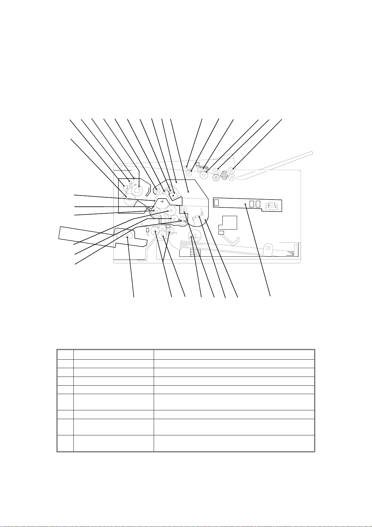
COMPONENT LAYOUT
1.3. COMPONENT LAYOUT
1.3.1. Mechanical Components
9
16
17
18
19
20
15
13
12
11
1014
87
5
6
4
1
21
22
23
24
25
26
27
28
29
30
No. Name Description
R2 Roller Feeds the document through the scanner.
1
R1 Roller Feeds the document through the scanner.
2
Document Feed Roller Feeds the document into the scanner.
3
Separation Pad Allows one page into the scanner.
4
Pick-up Roller Picks up pages of the document from the document
5
Pressure Plate This applies pressure against the pick-up roller.
6
CTM (Cleaning Toner
7
Magazine)
Used Toner Tank This removes and stores excess toner from the master
8
table one at a time.
This consists of the toner cartridge, cleaning unit, used
toner tank, charge corona unit, and quenching lamp.
after image transfer. It is part of the CTM.
H516V501.wmf
1-6

August 2nd, 1995 OVERALL MACHINE INFORMATION
COMPONENT LAYOUT
No. Name Description
Charge Corona Unit This applies a charge to the drum at the start of the
9
Quenching Lamp This removes excess charge from the master at the
10
Cleaning Blade This wipes toner off the OPC drum.
11
Used Toner Collection
12
Roller
Hot Roller Heat from this roller fuses the toner to the copy paper.
13
Cleaning Pad This cleans up and spreads silicone oil on the surface
14
Hot Roller Strippers These take the paper off the hot roller after fusing.
15
Paper Feed-out Rollers These feed the paper out of the printer.
16
Fusing Pressure Roller This applies pressure to the paper during the fusing
17
OPC Drum The latent image is written to this Organic
18
Development Unit This consists of the development roller, toner
19
Transfer Roller This applies a charge to the paper to pull the toner off
20
Development Roller This roller applies toner to the latent image on the drum.
21
Toner Application Roller This roller transfers toner to the development roller.
22
Toner Supply Bar This stirs up and transfers toner to the toner application
23
Paper Feed Rollers (100
Sheet Cassette)
24
Paper Feed Pressure
25
Rollers
Registration Roller This carries out the registration process.
26
Paper Feed Rollers These pick up the top sheet of paper from the stack in
27
Toner Supply Roller This supplies toner to the development unit. It is part of
28
Toner Agitator This stirs up toner in the toner tank, so that it does not
29
Toner Tank This supplies toner to the development unit. It is part of
30
Laser Unit This consists of the LDDR (Laser Diode Driver),
31
print cycle. It is part of the CTM.
end of the print cycle. It is part of the CTM.
This catches the used toner and the transfers the toner
to the used toner tank. It is part of the CTM.
of the hot roller.
process.
Photoconductor Drum.
application roller, toner supply bar, and transfer roller.
the drum and onto the copy paper.
roller.
These pick up the top sheet of paper from the stack in
the optional 100 sheet cassette and feed it into the
printer.
These feed paper from the cassette or bypass feed slot
into the printer.
the cassette and feed it into the printer.
the toner tank.
collect into lumps.
the CTM.
Focusing lens, Fθ Lenses, Hexagonal mirror motor, and
other laser optic components.
1-7
2
3
22
OVERALL MACHINE INFORMATION August 2nd, 1995
COMPONENT LAYOUT
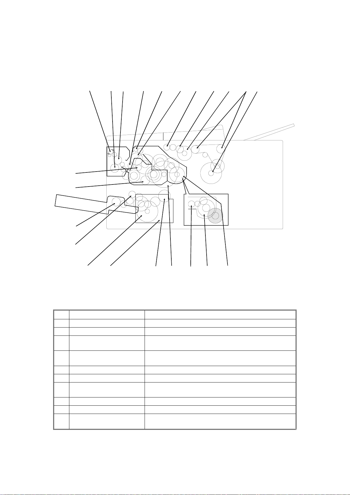
1.3.2. Drive Components
12
13
14
15
11
10
9
8
7
56
4
1
21
16
17
18
19
20
No. Name Description
Tx Motor This stepper motor drives the scanner.
1
R1/R2 Rollers These feed the document through the scanner.
2
Document Feed Drive
3
Gear
Document Feed Roller
4
Drive Gear
Pick-up Roller Drive Gear This drives the pick-up roller.
5
Drum Drive Gear This drives the drum.
6
Used Toner Collection
7
Roller Drive Gear
Transfer Roller Drive Gear This drives the transfer roller.
8
Hot Roller Drive Gear This drives the hot roller.
9
Fusing Pressure Roller
10
Drive Gear
This drives the document feed and pick-up rollers.
This drives the document feed roller.
This drives the used toner collection roller (magnetic) in
the used toner tank.
This drives the pressure roller in the fusing unit.
H516V502.wmf
1-8

August 2nd, 1995 OVERALL MACHINE INFORMATION
COMPONENT LAYOUT
No. Name Description
Paper Feed-out Roller This feeds printouts out of the machine.
11
Development Roller Drive
12
Gear
Toner Application Roller
13
Drive Gear
Paper Feed Roller Drive
14
Gear (100 Sheet Cassette)
Registration Roller Drive
15
Gear
Paper Feed Motor This stepper motor drives the paper feed mechanisms
16
Paper Feed Roller Drive
17
Gear Box
Paper Feed Roller Drive
18
Gear
Main Motor This brushless dc motor drives the drum, fusing unit,
19
Toner Supply Gear This ensures the supply of toner from the toner tank in
20
Toner Agitator Drive Gear This drives the toner agitator.
21
CTM Drive Gear This drives the CTM.
22
This drives the development roller.
This drives the toner application roller.
This drives the paper feed roller in the optional 100
sheet cassette.
This drives the registration roller.
and the registration roller.
The gears in this box drive the paper feed roller in the
main cassette.
This drives the paper feed roller.
development unit, and CTM.
the CTM, and its distribution across the full length of
the development unit.
1-9
5
6
OVERALL MACHINE INFORMATION August 2nd, 1995
COMPONENT LAYOUT
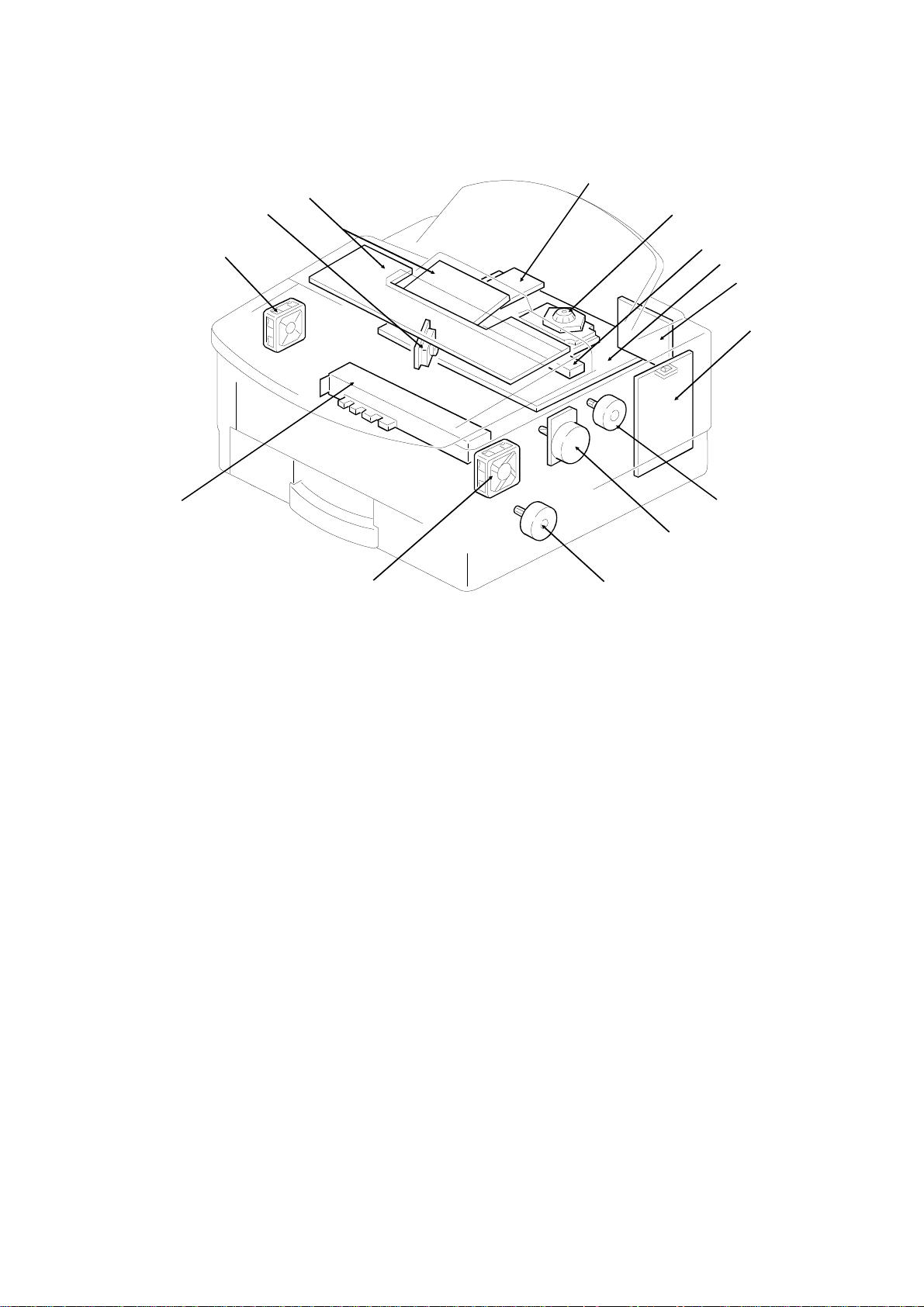
1.3.3. Electrical Components
7
8
10
9
4
3
2
1
14
13
11
12
H516V503.wmf
1-10

August 2nd, 1995 OVERALL MACHINE INFORMATION
COMPONENT LAYOUT
1. PCBs
No. Name Description
FDU (Facsimile Driver
Unit)
3
FCE (Facsimile Control
6
Engine)
NCU (Network Control
2
Unit)
OPU (Operation Panel
7
Unit)
PSU (Power Supply Unit) This board supplies power to the machine, and
1
LDDR (Laser Diode
8
Driver)
Power Pack This supplies high voltages to the corona wire, transfer
10
Contact Image Sensor
Assembly
4
This board contains drivers for the motors, a dc-dc
converter, the energy saving mode cpu, and other drive
electronics.
This board controls the machine. It contains the main
cpu, flash ROM, system RAM, and so on.
This board contains a relay and switches for interfacing
the machine to the network and the handset.
This board controls the operation panel.
switches the fusing lamp on/off.
This board drives the laser diode.
roller, and development rollers.
This sensor reads and converts the light reflected from
the document into an analog video signal. It uses an
RLA (Rod Lens Array) sensor unit.
An LED array which illuminates the document is
contained in this unit.
2. Motors
No. Name Description
Tx Motor This stepper motor drives the scanner.
14
Main Motor This brushless dc motor drives the drum, fusing unit,
13
Paper Feed Motor This stepper motor drives the registration roller and the
12
Hexagonal Mirror Motor This high-speed dc motor drives the hexagonal mirror
5
Ozone Fan Motor This removes ozone-laden air from the vicinity of the
9
Cooling Fan Motor This cools the interior of the machine.
11
development unit, and CTM.
paper feed mechanisms in the cassettes.
in the laser printer optics.
drum, and filters out the ozone.
1-11

15
28
21
OVERALL MACHINE INFORMATION August 2nd, 1995
COMPONENT LAYOUT
20
22
19
23
24
18
25
17
26
27
16
29
33
32
31
30
H516V504.wmf
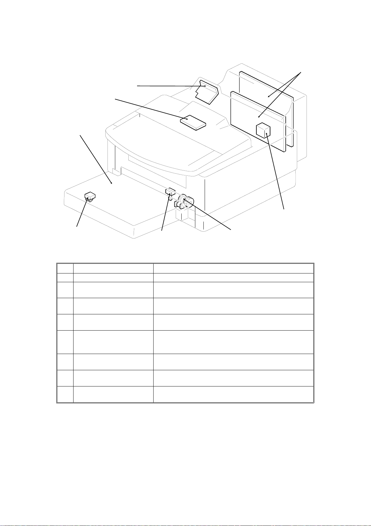
3. Sensors
No. Name Description
Document Sensor This detects the presence of a document in the feeder.
17
Scan Line Sensor This detects when a page is approaching the auto
15
Toner End Sensor This detects when the toner has run out.
31
Paper Size Detector This detects the paper size installed in the cassette.
27
Paper End Sensor This detects when the paper in the cassette has run out.
32
Registration Sensor This detects when paper has reached the registration
26
Fusing Exit Sensor This detects when the paper has been fed out of the
29
Fusing Exit Cover Switch This detects whether the fusing exit cover is open or
28
Bypass Feed Sensor This detects when a sheet of paper has been inserted
25
shading position.
The user must install the correct size indicator.
roller.
printer.
closed.
into the bypass feed slot. Then the registration roller
feeds the paper a short distance into the machine to
prepare for printing, and stops.
1-12

August 2nd, 1995 OVERALL MACHINE INFORMATION
COMPONENT LAYOUT
4. Interlock Switches
No. Name Description
Interlock Switches If the fusing unit cover and/or top cover are open, these
30
interlock switches interrupt the +5VLD power supply for
the laser diode and the +24VD power supply for the
power pack, motors, and other components.
5. Others
No. Name Description
Stamper Ass’y This stamps a red circle on each page that is
16
Quenching Lamp This removes excess charge from the drum at the end
20
Charge Corona Unit This applies a charge to the drum at the start of the
21
Thermostat This interrupts the ac power supply to the fusing lamp if
23
Thermistor This monitors the temperature at the hot roller surface.
24
Fusing Lamp The heat from this lamp fuses the toner to the paper.
22
Monitor Speaker This allows the user to listen to the condition of the
18
Zener Diode This ensures that the charge given to the drum by the
33
Ozone Filter This removes ozone-laden air from the vicinity of the
19
succe ssfully fed through the scanner.
of the print cycle. This is a part of CTM.
print cycle. This is a part of CTM.
the temperature of the thermostat surface exceeds
400°C.
telephone line.
charge corona wire does not exceed -750 volts.
drum.
1-13
OVERALL MACHINE INFORMATION August 2nd, 1995
COMPONENT LAYOUT
6. Optional Equipment
35
36
37
38
39
40
41
No. Name Description
Counter This counts the number of prints.
34
Printer Interface This allows the machine to be connected to a computer
35
RS232C Interface Board* This allows the machine to be connected to a computer
36
IC Card This increases the SAF memory capacity. Either a 2
37
100 Sheet Cassette This increases the paper capacity of the machine, and
38
Paper Size Detector (100
39
Sheet Cassette)
Paper End Sensor (100
40
Sheet Cassette)
Paper Feed Clutch (100
41
Sheet Cassette)
as a laser printer.
as an external fax device, for example.
MB or 4 MB card can be used.
allows the machine to have more than one paper size
available at the same time.
This detects the paper size installed in the cassette.
This detects when the paper in the cassette has run out.
This transfers drive from the paper feed motor to the
paper feed roller in the cassette.
34
H516V505.wmf
* This option may not be available in some countries.
1-14
August 2nd, 1995 OVERALL MACHINE INFORMATION
OVERALL MACHINE CONTROL *
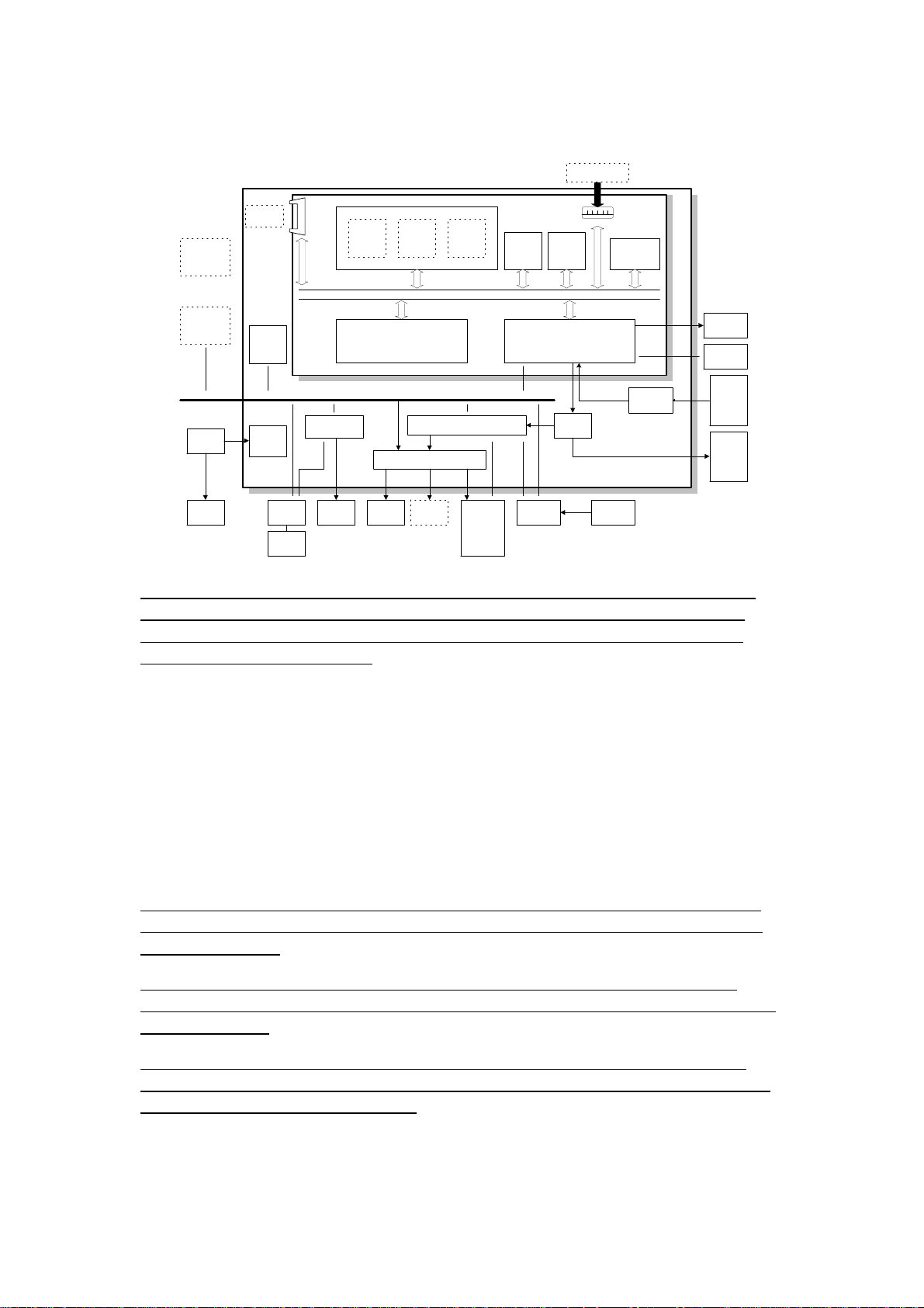
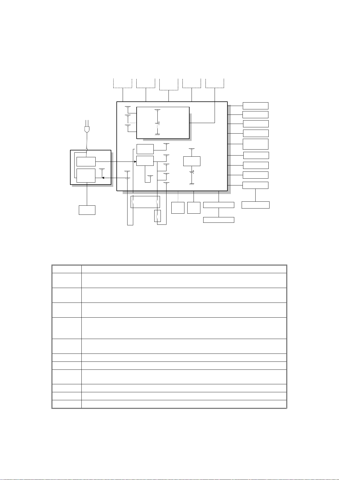
1.4. OVERALL MACHINE CONTROL *
Optional
RS232C I/F
Optional
Optional
100 Sheet
Cassette
Optional
Printer I/F
PSU
Fusing
Lamp
IC Card
FDU
Energy
Saver
CPU
DC-DC
Converter
FCE2
Handset
Hybrid IC
(HIC)
SpeakerNCU
Working
Control Signals
The FCE2 (Facsimile Control Engine) contains the FCIP (Facsimile Control
and Image Processor), DRAM, SRAM, System RO M, R14 4EF XL modem,
and video processing memory, and controls the entire system thro ugh the
FDU (Facsimile Driver Unit).
RAM
R144EFXL
Modem
Power
Pack
DRAM
ECM/SAF
Memory
DATA/ADDRESS BUS
External I/O (EXIO)
Driver
Optional
Counter
Page
Memory
components
Scanner
and
printer
and
sensors
System
ROM
(Flash)
Operation
Panel
System
RAM
(SRAM)
FCIP
Drivers
(FPD)
Sensors
Video
SRAM
Amplifier
LDDR
Thermistor
Contact
Image
Sensor
Tx
and
paper
feed
motors
H516V506.wmf
There are two cpus in the machine: th e main cpu (FCIP) o n the FCE and the
energy saver cpu on the FDU. In energy saver mode, the main CPU switches
off and the energy saver CPU takes over.
The FCIP consists of the following component blo cks:
• MDM - Modem• RU8 CPU - Main CPU
• DMAC - DMA Controller• LIF- Laser Interface
• DIP - Digital Image Processor• PRIF - Printer Interface
• DCR - Data Compression and Reconstruction
The modem inside the FCIP is used for V.29, V27.ter, and V.21 communications. In addition, the Ro c k well R144E F XL modem is used for V.17 and V.33
communications.
The 1.5 MB DRAM contains the SAF memory, ECM buffer memory, work
area, and page memory. The SAF memory can be extended by 2 or 4 Mbytes
with an IC card.
A 512 kB (4 Mbit) flash ROM is used for the syste m ROM. So ft ware in this
ROM can be rewritten from the IC card slot or by RDS. Another 128 kB mask
ROM contains LCD wording data.
1-15
OVERALL MACHINE INFORMATION August 2nd, 1995
VIDEO DATA PATH
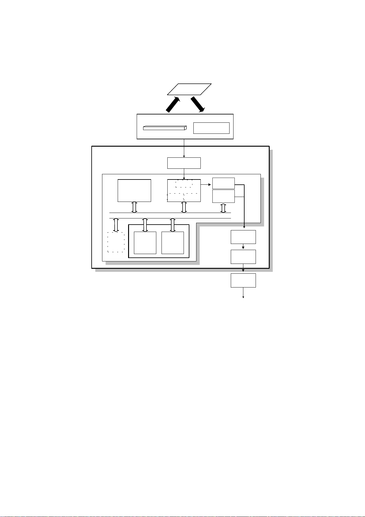
1.5. VIDEO DATA PATH
1.5.1. Transmission *
Original
Contact Image Sensor
Assembly
LED Array
Image Sensor
FDU
Amplifier
FCE
Attenuator
HIC
NCU
Video
Processing
Memory
DRAM
SAF IC
Card
DIP: Digital Image Processor
Line
Buffer
/FIFO
Memory
FCIP
DCR
DATA/ADDRESS BUS
ECM/
SAF
Memory
DIP
MDM
Amp
E144EFL
Modem
DCR: Data Compression & Reconstruction
MDM: Modem
To the network
H516V507.wmf
Immediate Transmission:
Scanned data from th e contact image sensor passes to the DIP block in the
FCIP. Af te r an alo g/ digital video processing, the DCR block compresses the
data for transmission . The compressed data then passes either to the FIFO
memory or to the ECM memory before it is sent to the telephone line through
the modem.
Memory Transmission:
First, the scanned data is sto red in the SAF mem o ry after compression in th e
DCR block.
At the time for transmission, the DCR block d eco mpre sses th e data from th e
SAF memory, then compresses it again after handsh aking with the other terminal is done. The compressed da ta the n passes eit he r to the FIFO memory
or to the ECM memory, before it is sent to the telephone line thro ugh th e
modem.
1-16
August 2nd, 1995 OVERALL MACHINE INFORMATION
VIDEO DATA PATH
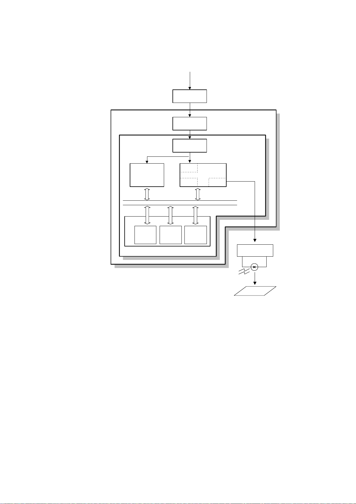
1.5.2. Reception *
From the Network
NCU
HIC
Amplifier
E144EFXL
DRAM
Line Buffer
Modem
/FIFO
Memory
DATA/ADDRESS BUS
ECM/SAF
Memory
MDM
FCIP
DCR LIF
Page
Memory
LDDR
LIF: Laser Interface
DCR: Data Compression & Reconstruction
MDM: Modem
Copy Paper
H516V508.wmf
Data from the lin e p asses to the modem through the NCU and hybrid IC. After the modem de mod ulates the data, the decompressed data pa sses to the
DCR block, through either the FIFO or the ECM memory, where the data is
decompressed to raster image data. At the same time, the compressed data
passes to the SAF memo ry as a backup in case of mechanical problems during printing (substit ute reception).
The raster image data is then p asse d t o t he pa ge memo ry for printing. Afte r a
page of data has been stored in the page memory, the data is sent to the
LDDR through the LIF block.
1-17
OVERALL MACHINE INFORMATION August 2nd, 1995
VIDEO DATA PATH
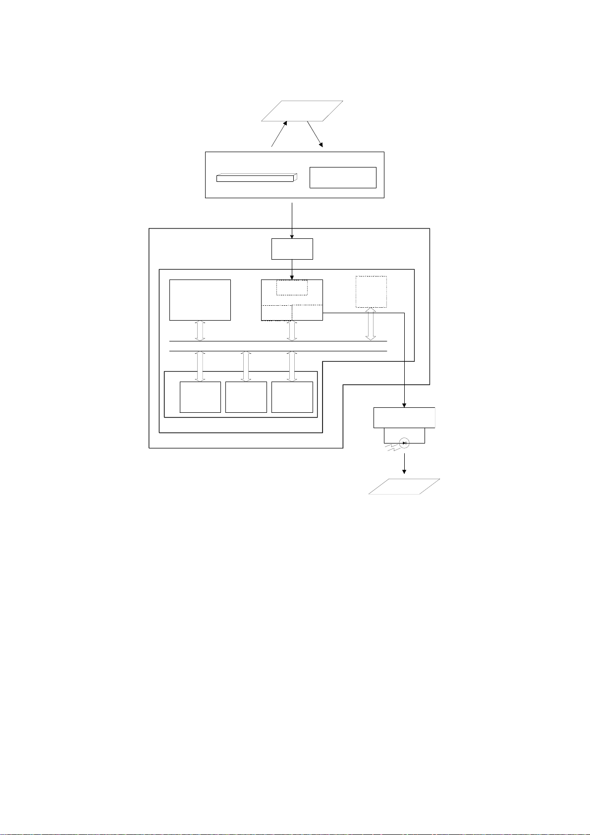
1.5.3. Copying
Original
Contact Image Sensor Assembly
Image Sensor
LED Array
FDU
Amplifier
FCE
LDDR
DRAM
Video
Processing
Memory
Line Buffer
/FIFO
Memory
DCR
DATA/ADDRESS BUS
ECM/SAF
Memory
DIP
FCIP
Page
Memory
LIF
SAF
Memory
IC Card
LIF: Laser Interface
DCR: Data Compression & Reconstruction
DIP: Digital Image Processor
Copy Paper
H516V509.wmf
Single copy
The scanned data passe s to th e pa ge memory after video processing in the
DIP block. After a page of data ha s be en sto red in the page memory, the data
is sent to the LDDR through the LIF block.
Multi-page copy
The scanned data passe s to th e SAF memory after vid eo proce ssing (DI P)
and compression (DCR). After a pa ge of da ta ha s be en stored in the SAF
memory, the data passes to the DCR block again for de compression, then it
passes to the page memory for print ing.
1-18

August 2nd, 1995 OVERALL MACHINE INFORMATION
VIDEO DATA PATH
1.5.4. Printing from the Optional Printer Inter face
Optional Printer
Interface
FDU
FCE
PRIF
FCIP
LIF
LDDR
LIF: Laser Interface
PRIF: Printer Interface
Copy
Paper
H516V510.wmf
The page memory inside the printer interface is used to hold the print data.
After a page of data has be en stored in the printer interface’s page memory,
the data is sent to the LIF through the PRIF (Printer Interf ace) block.
1-19
OVERALL MACHINE INFORMATION August 2nd, 1995
POWER DISTRIBUTION
1.6. POWER DISTRIBUTION
1.6.1. Distribution Diagram *
AC Switching
Circuit
Fusing Lamp
ON/OFF
Circuit
AC
Main
Power
Main Switch
PSU
24VIN
IC
Card
+24VM
+24VD
Optional
Counter
+12VP
+24V
+5V
+5VD
+12VD
+5VD
+5V
+24VD
FCE
DC-DC
Converter
DC-DC
Converter
-5V
Optional 100
Cassette
+5VBAT
Sheet
+24VM
+5V
12VP
+5V
+5VE
+5vv
+5VLD
Printer
I/F
+5VD
DC-DC
Converter
+24V
+5V
RS232C
I/F
+5V
FDU
+24VM
+24VM
+24VD
+24VD
+24VD
+24VD
+5V
+5V
+5V
+5VE
+5V
Optional PFU
Motors
Feed Clutch
Stamp
Cooling Fan
Ozone Fan
Power Pack
Thermistor
Printer Sensors
Operation Panel
AC115V or 230V
Fusing
Lamp
Fusing Unit
Interlock
Switches
LDDR
+5VLD
+24V
NCU
+5VE
+24VM
+5V
+5VV
-5V
Image Sensor
+24VM
LED Array
+5VE
Scanner Sensors
H516V511.wmf
The PSU supplies +24V dc power to the FDU. The FDU converts the +24V
dc power supply to the following supplies.
+5V
+5VE
+5VLD
+5VV
+5VD
+5VBAT
+24V
+24VD
+24VIN
+24VM
-5V
+12VP
This is normally on when the main switch is on.
This is used for detecting an activation signal from the NCU, document feeder,
or operation panel when the machine is in energy saving mode.
This supplies the laser diode. It is interrupted if the fusing unit cover interlock
switch opens.
This is a more stable power supply than +5V. It is used for the Contact Image
Sensor.
This supplies back up power for the DRAM and the optional IC card on the
FCE. It can back up stored data for one hour after the power is switched off.
A rechargeable battery on the FDU is used to generate +5VD.
This supplies back up power to the system RAM on the FCE to back up the
programmed data. A lithium battery is used to generate +5VBAT.
This is normally on when the main switch is on.
This is interrupted if the fusing unit cover interlock switch opens.
This supplies +24V to the fusing unit on/off switching circuit. It is interrupted if
the fusing unit cover interlock switch opens.
This is interrupted if the machine enters energy saving mode.
This is used for the image sensor.
This is supplied to the Flash ROMs on the FCE and the optional IC card.
1-20
August 2nd, 1995 OVERALL MACHINE INFORMATION
POWER DISTRIBUTION
1.6.2. Memory Back-up Circuit
[A]
[B]
H516V512.wmf
The +5VBAT supply from the lithium battery [A] backs up the system RAM
which contains system paramet ers an d pro gra mmed tele ph one nu mbe rs,
and the real time clock in the main cpu. The 5RTCCS signa l tells th e main
cpu whether the back-up po wer (+5 VB AT) is coming from the bat te ry or from
the +5V power suppl y.
A rechargeable lithium ba tt ery [B ] and th e dc/dc converter on the FDU back
up the DRAM (SAF memory) for one hour, if there is data in the SAF memory
and the power is switched off . While the main power is o n, the +5VE supply
recharges the battery. The battery recharges in one or t wo d a ys.
The battery [B] generates about 3 volts (max. 3.2 volts). The dc/ dc co nverter
(IC12) lifts this voltage to 5 volts so it can be used as the +5VD supply for
SAF backup. The CPU monitors th e volt age of the +5V D supply with the
1VDET signal. When the battery has run down, and the voltage is lower than
4.4 volts, the CPU stops the dc/dc converter by dropping 1SAFFG to low and
the machine stops backing up the memo ry.
There is no battery switch for the battery [B].
1-21
[A]
H516D503.wmf
August 2nd, 1995 DETAILED SECTION DESCRIPTIONS
SCANNER
2. DET AILED SECTION DESCRIPTIONS
2.1. SCANNER
2.1.1. Mechanisms
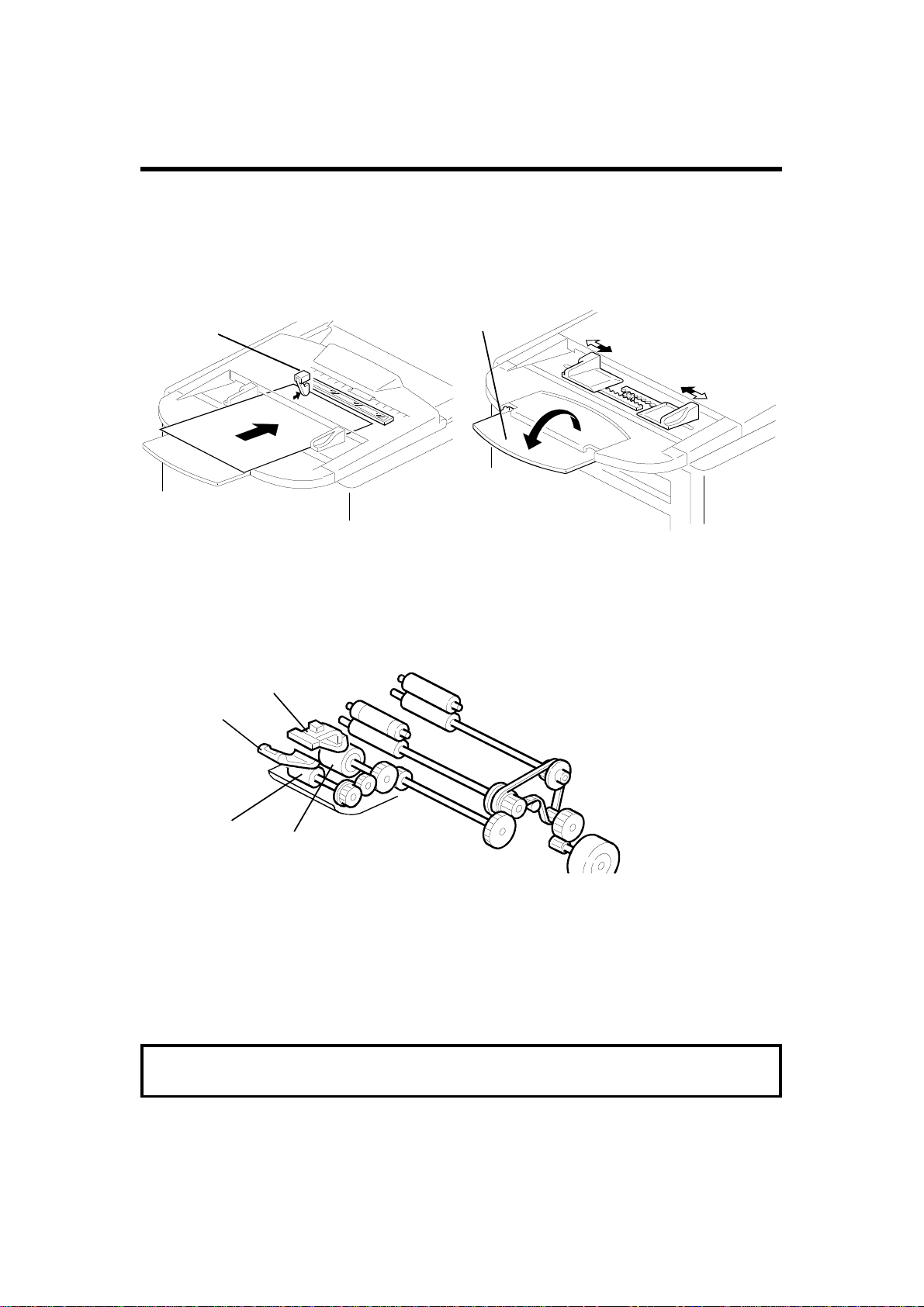
1. Document Detection
[A]
[B]
H516D501.wmf
H516D500.wmf
The document sensor [A] detects when a document is pla ced in the ADF. The
fold-down extension [B] help s to sup po rt lon ge r documents.
2. Pick-up and Separation
[D]
[B]
[C]
Plate [A] aligns the leading edges of the pages of the document. When the
machine starts feeding the docu men t, the mechanical clutch mechanism in
the ADF roller unit lifts up the p ick-up roller [B] to feed the bottom sheet of the
document. Then, the feed roller [C] feeds th e sh ee t in to th e sca nner.
The separation rubber plate [D] prevents the feed rolle r from fe ed ing more
than one sheet at a time.
Cross reference
ADF mechanical clutch mechanism: Group 3 Facsimile Manual, page 2-2-8
2-1
 Loading...