

Page 1

Technical Bulletin No. F/L Series-001
SUBJECT: Introduction of the New Tools for ROM/RAM Data Change
PREPARED BY: Y. Okunishi
CHECKED BY: M. Iwasa
CLASSIFICATION:
Action Required Revision of service manual
Troubleshooting Information only
Retrofit Information Other
The following service tools have been de velo pe d to chan ge ROM a nd RAM dat a fo r F/ L serie s
machines.
1. RRW ( Remote ROM Writer )
Software in ROM can be changed remo te ly sin ce a Flash ROM is use d fo r F/L series machines.
The RRW is a software package that runs in a Personal Computer with an external class 1
modem of a type recommended by Ricoh and can change the RO M dat a in F/L series
machines through th e te lephone network.
Please contact Ricoh to order t he RRW. It will be rele ase d in May 1995 .
FROM: 2nd T.S. Section
MODEL:
DATE:
Apr. 30, 19 95
FX6, FX4, LSO
2. RDS Version 2.0
The new RDS Version 2.0 runs in a Personal Comp ut er with an external class 1 modem of a
type recommended by Ricoh and can change RAM data such as Quick Tel. Numb ers,
Bit switches, RTI etc. ... in remo te fax mach ines made by Ricoh through the tele phon e network.
This RDS can also change ROM data in Ricoh made fa x machines that use flash ROMs.
Please contact Ricoh to order RDS Versio n 2.0. It will be rele ase d in Jun e 1995 .
3. Flash ROM/SRAM Copy Tool ( P/N: H5159100 )
This is an interface card between the FCE inside the machin e an d an FCE outside the machine.
There are three purposes for this tool.
[1] Transferring user data in the RAM su ch as Qu ick Tel. Numb ers, Bit Switches, etc. ...
in an FCE removed from a defective machine to a new FCE installed in the machine.
[2] Updating the ROM inside the machine from an FCE or EPROM Board outside the machine
without replacing the ROM.
[3] Copying the ROM data inside the machine into the ROM on an FCE outside the machine.
This tool is available at the Spare Parts Center.
Page 2

Technical Bulletin No. F/L Series-001
SUBJECT: Introduction of the New Tools for ROM/RAM Data Change
4. EPROM Board
This is a tool for updating the ROM inside the machine without repla cing the ROM.
Programmed EPROM(s) can be installed on the EPROM board .
The EPROM Board is connected to the Flash ROM/SRAM Copy Tool and the data in the
EPROM is transferred to the Flash RO M inside the machine through the Flash ROM/SRA M
Copy Tool.
Please contact Ricoh to order EPROM Board.
DATE:
Apr. 30, 19 95
Page 3
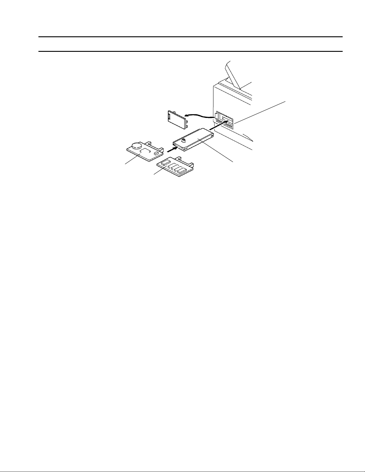
Data Copy Tools for the F/L Series
[A]
April 21st, 1995
[D]
[B]
[C]
A: Flash ROM / SRAM Copy Tool (H515 9100)
B: PCB-FCE
C: EPROM Board
D: Memory card slot
Note: In the LSO, the
NCU Cover, Front Cover
and Left Cover have to be
removed to set the Flash
ROM/SRAM Copy Tool.
The Flash ROM / SRAM Copy Tool [A] is inserte d int o the memory card slot [D],
then the FCE [B] or EPROM Board [C] with new software is connected to the opposite side
of the tool.
ROM Data Download
This function copies soft ware from an exte rnal medium to the Flash ROM on the machine’s
FCE. The external medium for the new sof twa re can be an FCE [B] or an EP ROM Board [C].
ROM Data Upload
This function copies the soft ware from the machine’s built-in FCE to an ext ern al FCE [B ].
This function does not work with an EPRO M Boa rd [C] .
SRAM Data Download
This function copies all the dat a stored in the SRAM on an external FCE [B] to the ma chin e’s
FCE. Use this after replacing a damaged FCE to save any previous settings that were
programmed in the damaged FCE.
Page 4
Note:
1) SRAM data upload is not available .
2) Refer to the service manual for the opera tio n pro cedure.
3) The blank EPROM (P/N H082 7110) wh ich is 150 ns or 120n s spee d fo r the CFO can be
used for the FX4. However, it cannot be used fo r t he FX6 an d the LSO.
The blank EPROM (P/N 19050020) which is 100ns spee d can be used fo r the FX6,
the LSO, and the FX4.
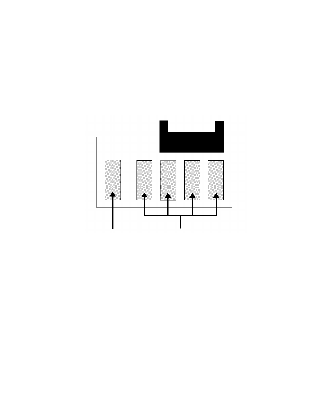
SLOT
EPROM BOARD
6 5 4 3 2 1
FX6 / LSO EPROM (1)
FX4 EPROMs (4)
Page 5

Technical Bulletin No.F/L Series-002
SUBJECT: Fax FX6CD (FAX2400L) Information DATE: June 30, ’95
PAGE: 1 of 1
PREPARED BY: K. Misugi
CHECKED BY: M. Iwasa
CLASSIFICATION:
Action Required
Troubleshooting
Retrofit Information
The new model FX6CD has been released in the line-up of FX6 (FAX 2700L) series.
The FX6CD is almost the same as the FX6. Please see the folllowing table for the
differences in specifications between the two machines.
Optional 100 sheet cassette Available Not Available
Optional Mech. Counter Available Not Available
Bypass Feeding Available Not Available
SAF Memory Backup Available Not Available
Stamp Available Not Available
Revision of service manual
Information only
Other
FROM: 2nd Technical Support Section
MODEL:
FAX 2400L
FX6 FX6CD
The following parts for the FX6CD are different from the FX6.
Index Name
FX6 FX6CD
1 PCB - FCE H5166002 H5276002
2 PCB - FDU H5166003 H5276003
3 Manual Feed Table H5163437 H5273437
4 Cover - Operation Panel H5164221 H5274221
5 Stamp Solenoid H5155005 Not used
6 Harness - 100 sheet cassette H5155085 Not used
7 Polygonal Mirror Motor H5215061 H5275061
8 Laser Plotter Unit H5212040 H5272040
9 Operator’s Manual H5168600 H5278600
Note:
Since the stamp is not available in the FX6CD, the Stamp Key on the operation panel is
used as the Printer Function Key when the optional printer interface unit is installed.
Please refer to the operation manual for details.
Part Number
Page 6
Technical Bulletin No. F/L Series-003
SUBJECT: Service Manual Corrections
DATE:
June 30, 1995
PREPARED BY: Y. Furuya
CHECKED BY: M. Iwasa
CLASSIFICATION:
Action Required Revision of service manual
FROM: 2nd T.S. Section
MODEL:
FX6
Troubleshooting Information only
Retrofit Information Other
Chapter 2
Section 2.2.1. Printing Process - Overview
Wrong Correct
Charge bias current and voltage -5.4 kV/ 305 µA -5.3 kV/ 300 µA
Zenor diode voltage 715V 698V
Transfer current +5 µA+4 µA
Section 2.2.2. OPC Drum
Wrong Sentence Correct Sentence
The toner application roller .. .. ., and
transport roller [E] are ...
Section 2.2.3. Charge
Wrong Sentence Correct Sentence
The corona wire [A] generate s ... . (th e
voltage is about -5.4 kV).
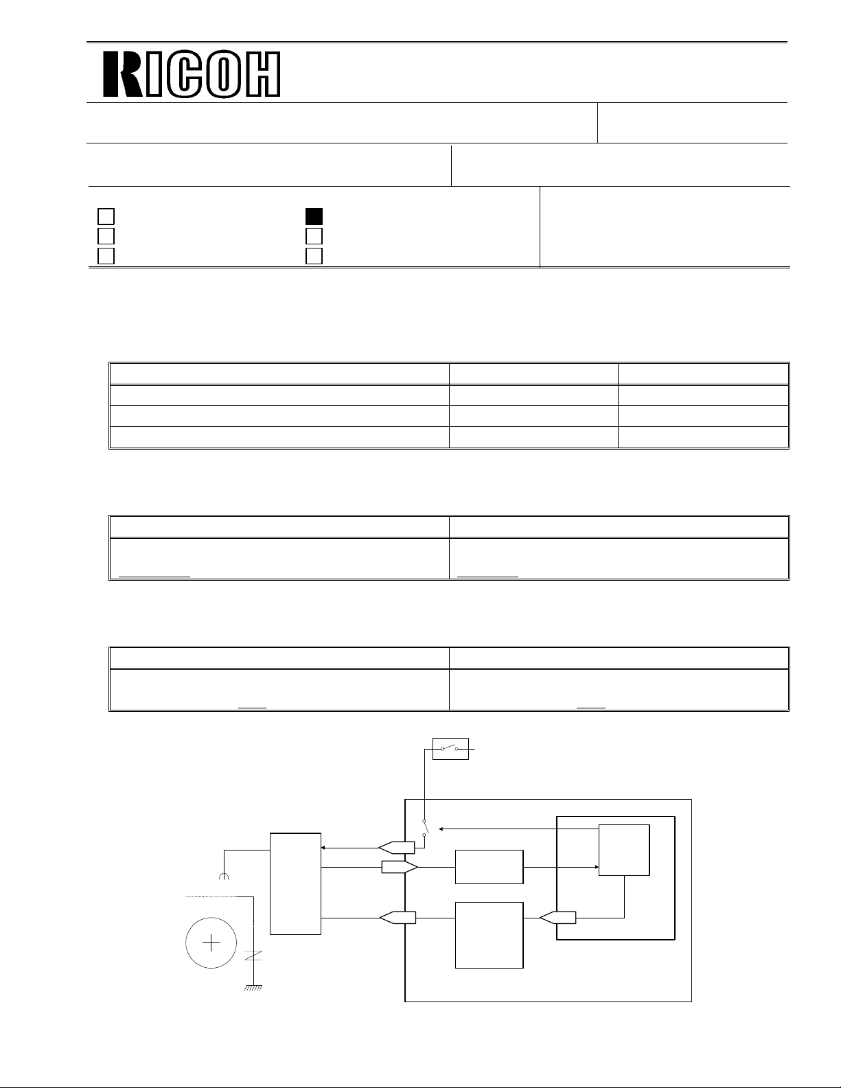
Power
Pack
-698 V
24VM
Leak Signal
Charge
21-1
21-8
21-3
The toner application roller ....., and
transfer roller [E] are ...
The corona wire [A] generate s ... . (th e
voltage is about -5.3 kV).
Fusing Unit Cover
Interlock Switch
ON/OFF
IC8
EXIO
IC4
Power
Pack
Driver
1-43
CPU
FCE
FDU
H516D557.wmf
Page 7
Technical Bulletin No. F/L Series-003
SUBJECT: Service Manual Corrections
DATE:
June 30, 1995
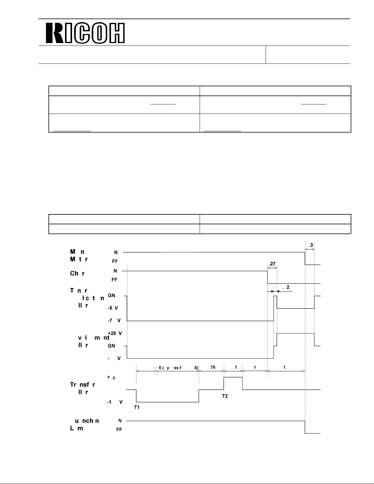
Section 2.2.4. - 2. Block Diagram
Wrong Sentence Correct Sentence
The LIF block in the .... . (FDU CN26-6) and
transfers ...
Speed of hexagonal mirror motor is:
7977.9 rpm
The LIF block in the .... . (FDU CN26-2) and
transfers ...
Speed of hexagonal mirror motor is:
7977.8 rpm
Section 2.2.7. Paper Feed - 1. Overview
Delete the following sentence from the first paragraph.
“The bypass feed slot can only be used in copy mode.”
Section 2.2.9. Transfer and Separatio n
Wrong Sentence Correct Sentence
A constant current of +5 +/- 0.2 µA is ... A const an t curre nt of +4 +/- 0.2 µA is ...
H516D563.wmf
Page 8

Technical Bulletin No. F/L Series-003
SUBJECT: Service Manual Corrections
DATE:
June 30, 1995
Section 2.2.11. Fusing - Service Call Conditions
Wrong Correct
Sub-code 05 ... more than 40 seconds ... ... more than 18 seco nds ...
Sub-code 02 ... to reach 150 deg.C from ... ... to reach 165 deg.C from ...
Sub-code 01 ... stays above 175 deg.C for ... ... stays above 190 deg.C for ...
Sub-code 03/04 ... go down to the standby
temperature when ...
... go down to 100 deg.C when ...
Chapter 3
Section 3.2. INITIAL PROGRAMMING
Add “Protocol Requirements (G3 Bit Switch 0B) - Function 01” in the “Items to Program
(Service Level)“ section. This is because these bit switch es must be enabled manu ally at
installation.
Chapter 4
Section 4.1.20. Software Download (Function 12) - Step 9
Section 4.1.21. Software Upload (Function 1 2) - Step 8
Section 4.1.22. SRAM Data Download (Function 12) - St ep 9
Wrong Sentence Correct Sentence
Turn off the machine, then turn it back on. Turn off the mach ine and disconnect the
tool. Then turn the mach ine back on .
Page 9
Technical Bulletin No. F/L Series-003
SUBJECT: Service Manual Corrections
Section 4.2. BIT S WITCHES
Switch Bit No. Wrong Correct
Third and fourth numbers:
... The left hand figure is the
low byte and the right hand
System 00 2
System-0F 0 - 7
G3-03 3
G3-08 0 - 3
G3-0B 0 - 5
figure is the high byte. ...
Cross reference NCU parameter 00
1: ECM reception is disabled,
which enlarges the SAF
memory.
Not used. PABX cable equalizers
These bits are automatically
set to the appropriate settin gs
after a country code (S yste m
Switch 0F) is programmed.
DATE:
June 30, 1995
Third and fourth numbers:
... The left hand figure is th e
high byte and the right hand
figure is the low byte. ...
Refer to “How to calculate the
rx level listed on the TCR
(Journal)“ below, for details.
Cross reference NCU parameter CC
1: The machine transmits with
a frame size of 64 bytes in
ECM. Set this bit to 1 when the
other terminal only has only a
64 byte frame size.
The bit assignments are
completely the same as PSTN
cable equalizer (G3 switch 07).
Manually program these bit
switches to match local
requirements.
How to calculate the rx lev el listed on the TCR (Journal)
Example: V29 96 L 01 0C 00 00
High byte
If bit 2 of system switch 00 is set to 1, the 4-digit hexadecimal value (=N) after t he lett er “L”
indicates the rx level. The calculation to get the actual rx level is given belo w.
[ Rx
level
(−dB) ] =
In the above example, the decima l va lue of 010C (H) is 268.
So, the actual rx level is -16.75 dB.
Decimal value of N
Low byte
16
Page 10

Technical Bulletin No. F/L Series-003
SUBJECT: Service Manual Corrections
Section 4.3. NCU PARAMETERS
Address (H) Wrong Correct
807F00 Function 08 (parameter 00) Function 08 (parameter CC)
807FA1/FA2 Factory setting: 2100 Hz See Note 2.
If the addresses for t one de te ction
Notes - 2
parameters contains FF(H), tone
detection is disabled.
Section 4.5. SERV ICE RAM ADDRE SSES
Address (H) Wrong Correct
80001E
8003AD
8003B2
8003FD
to
800404
Setting (1, 1, 1, 0) is Legal
sideways
Bit assignments:
Bits 0 to 2: Not used.
Unit of the update counter is
hexadecimal.
Setting (1, 1, 1, 0) is Legal
lengthwise
Bit assignments:
Bit 0: Edge detection du ring the
halftone process 0:Off, 1: On
Bit 2: Edge detection threshold
during the halfton e pro cess
0: Normal, 1: High
DATE:
June 30, 1995
Page 11
Technical Bulletin No. F/L Series-003
SUBJECT: Service Manual Corrections
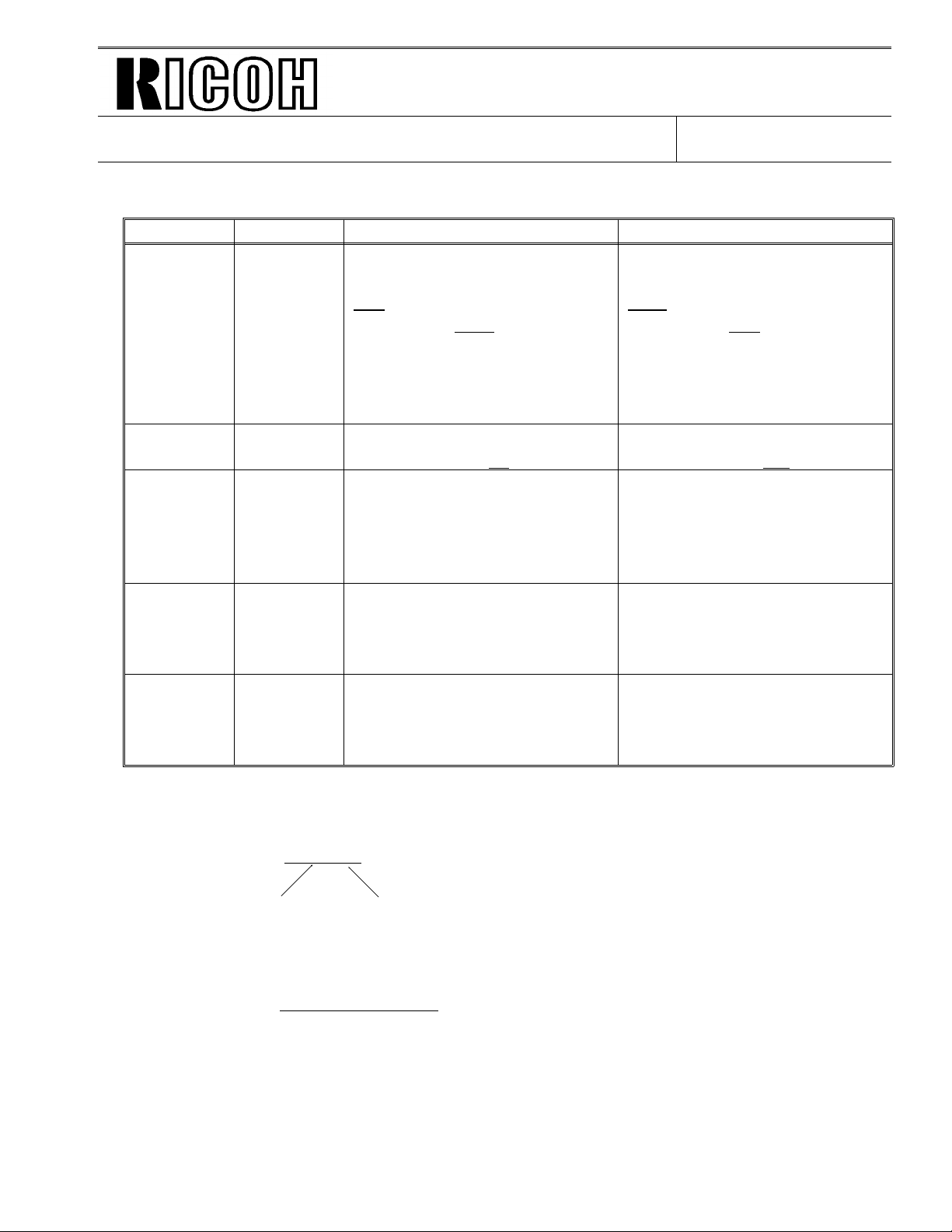
Chapter 5
Section 5.6. DEVELOPMENT UNIT
[A]
DATE:
June 30, 1995
[B]
H516R521.wmf
Use a small ( -) screw driver to release the ho oks [A ] an d [B] off the developme nt unit.
Section 5.9.3. Power Pack
Add a note “Do not touch the dials on the power pack when replacing the power pack.”
The three dials on the power packs are to be seale d with plast ic. However, the power packs
that were produced earlier do not have plastic seals on the dials. If you have power packs on
which the dials are not sealed, be caref ul no t to turn the dials.
Section 5.12.3. Margins (Main Scan Direction) - Parameter W1
Delete the following sentence from “Formu la”:
“2. How a setting affe cts printer interface outp ut. W1PIF = (Current settin g x 0.5 )/ 0.68 mm”
Page 12

Technical Bulletin No. F/L Series-003
SUBJECT: Service Manual Corrections
DATE:
June 30, 1995
Chapter 6
Section 6.3. SERVICE CALL CONDITIONS - Fusing Unit Failure
Wrong Correct
Sub-code 05 ... more than 40 seconds ... ... more than 18 seco nds ...
Sub-code 02 ... to reach 150 deg.C. ... to reach 165 deg.C.
Sub-code 01 ... stays above 175 deg.C for ... ... stays above 190 deg.C for ...
Sub-code 03/04 ... fall back to 80 deg.C. ... fall back to 100 deg.C.
Section 6.4. ERROR CODES - Error Code 0-24
Delete the followin g sentences from “Suggest ed Cause/Action”, because there is no such
adjustment available.
“Try changing the post-message command tx timin g.”
“Cross reference: Post message command tx timing”
Page 13
Page 1/1
Technical Bulletin No. F/L series-004
SUBJECT: Possibility of paper misfeed
PREPARED BY: T. Kimura
CHECKED BY: M. Iwasa
CLASSIFICATION:
Action Required Revision of service manual
Troubleshooting Information only
Retrofit Information Other
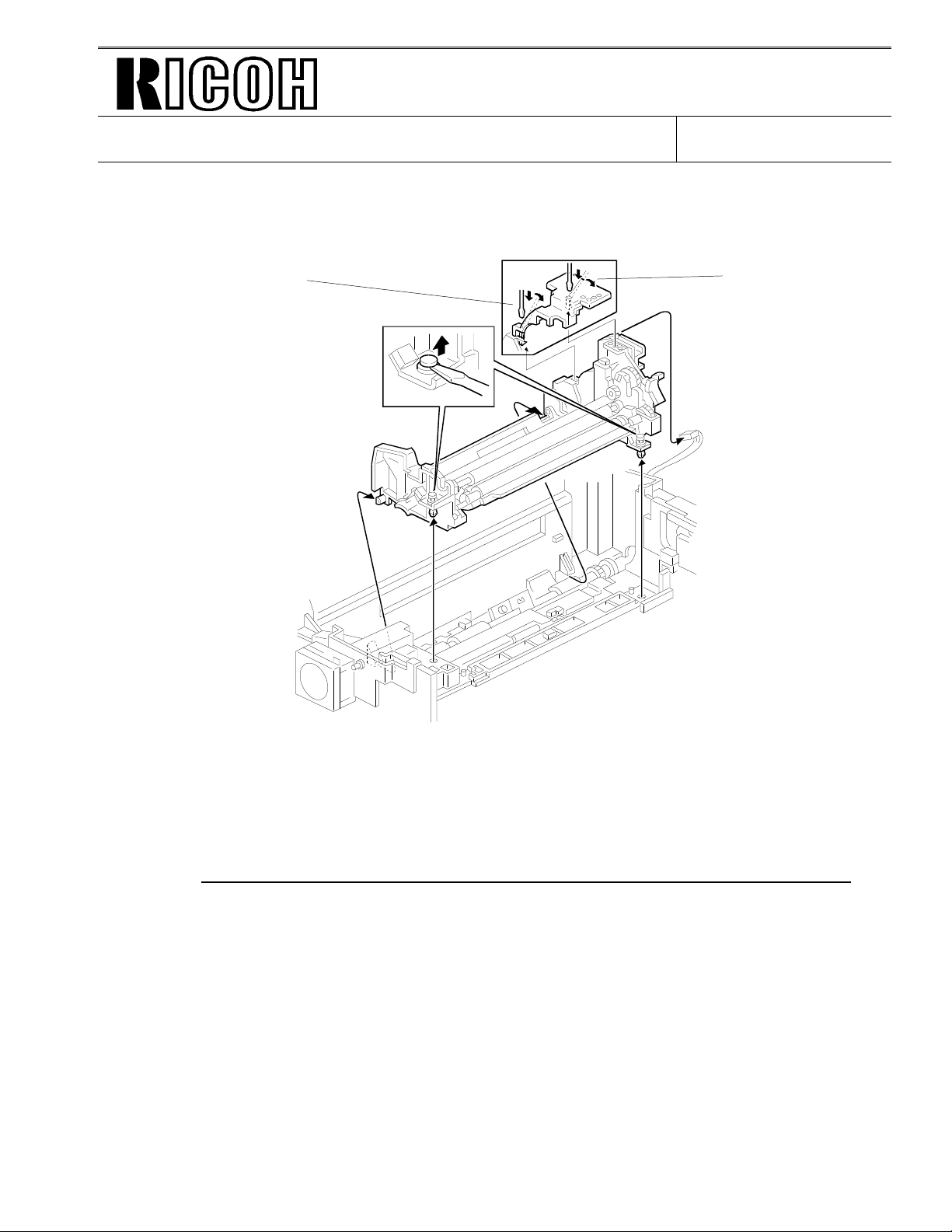
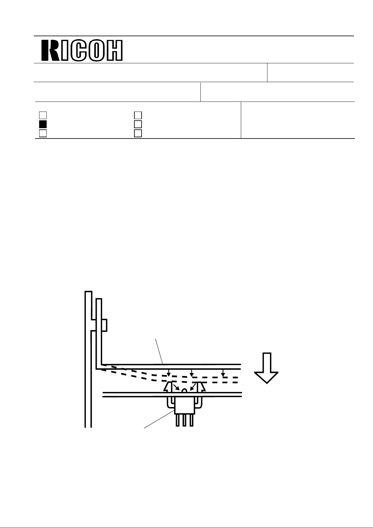
When peeling off tapes, in particular for the pape r ca sset te, please check if the glue from the
tape has been completely remo ved from the paper cassette bot to m p lat e.
If not, a paper misfeed may occur when the last shee t is fed , since it sticks to th e bott om plate.
Bottom plate
FROM: 2nd T.S. Section
MODEL:
DATE:
Aug. 31, 19 95
MV310
Glue from the tape
Page 14

Page 1/2
Technical Bulletin No. F/L series-005
SUBJECT: Unreleased side cassette locks
PREPARED BY: T. Kimura
CHECKED BY: M. Iwasa
CLASSIFICATION:
Action Required Revision of service manual
Troubleshooting Information only
Retrofit Information Other
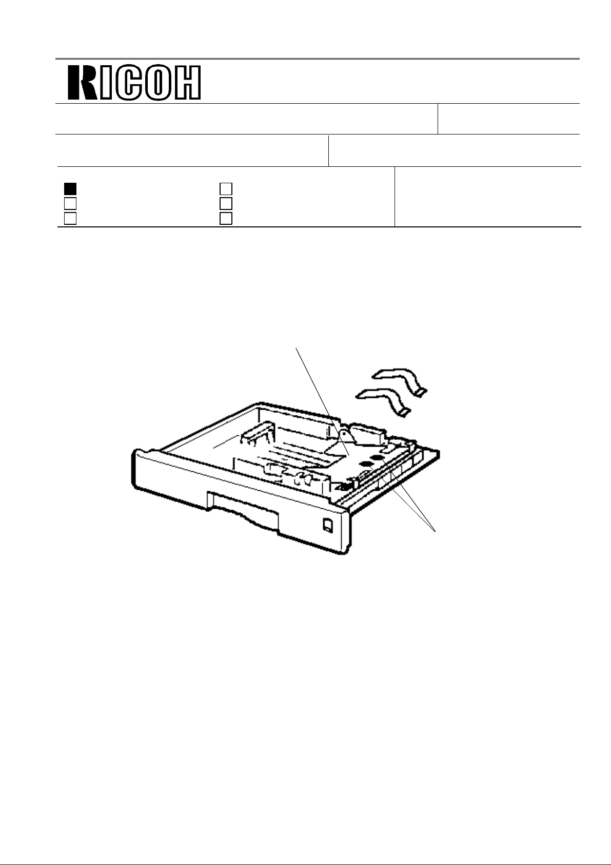
When installing the opt ion al side cassette, there may be a pro blem in which the lock of the
bottom plate is not released . If it is not released, paper end will be detecte d. This is becau se th e
height margin between the protuberan ce on the bot to m plate and the release lock lever is n ot
sufficient for the two parts to cont act .
To prevent this proble m, th e he ight adjustment part should be attached befo re inst alling the side
cassette.
Installation procedure:
See the atta che d procedure.
The machines to be modified:
The July production run or earlier, and the 633 August production run.
The serial numbers of the 633 machines are as follows:
FROM: 2nd T.S. Section
MODEL:
DATE:
Aug. 31,1 995
MV310
M0350800 001~032, 034~055, 059~097, 099, 101~103, 105~164, 169~386,
395~408, 417~476, 478~483, 485, 487, 489, 492, 494, 496, 498,
507~519, 522~532, 541, 543, 545, 548, 550, 552, 556, 558, 560,
562, 564, 566, 567, 569, 571, 573, 575~582, 584, 586, 588, 590,
591, 593, 595, 597, 645, 648, 649, 652~709, 711, 713, 715, 718,
720, 722, 724, 734, 736, 738, 740, 760, 761, 763, 765, 768, 770,
772, 774~ 807, 890, 891
Page 15
Clean here
Page 2/2
Technical Bulletin No. F/L series-005
SUBJECT: Unreleased side cassette locks
DATE:
Aug. 31,1 995
<Attachment>
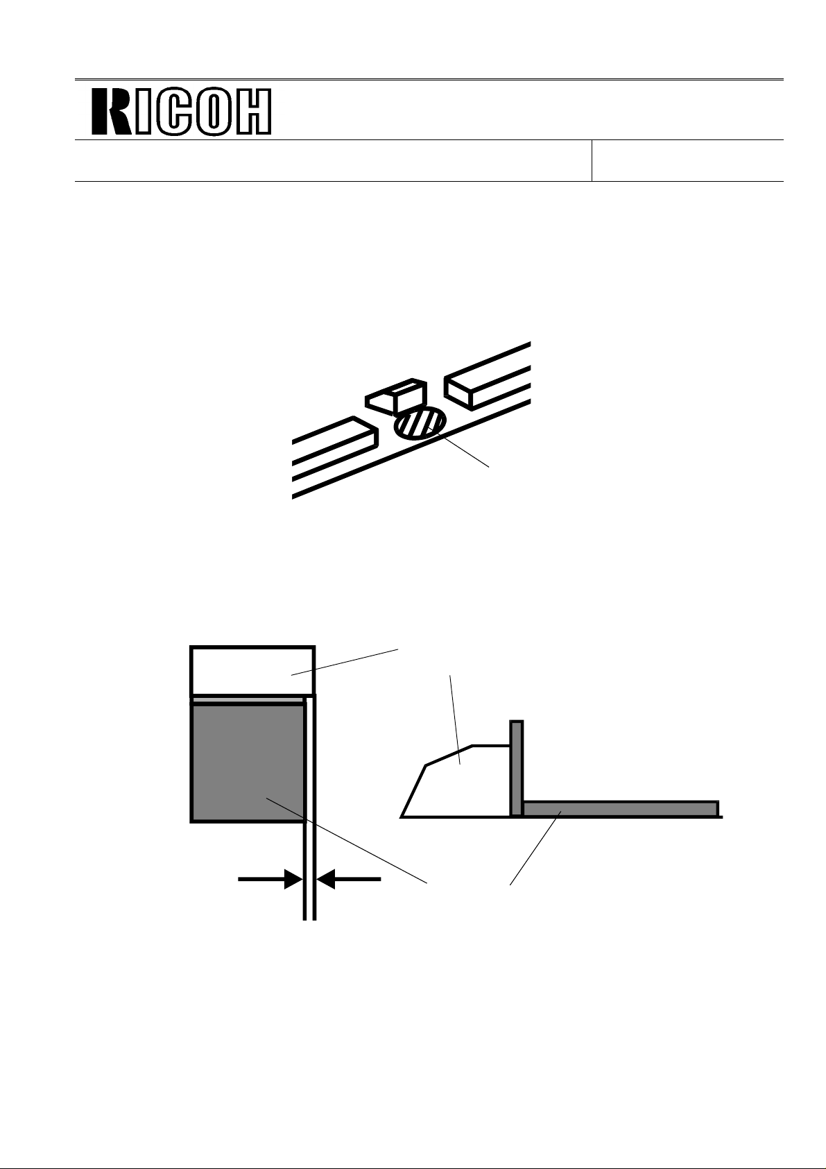
Installation Procedur e
1. Clean the portion on which th e pa rt will b e at ta ched with alcohol or wet cloth .
2. Peel off the backing of the part.
3. Attach the part.
Top view
0 ~ 0.5 mm
Side view
Protuberance
Height adjustment part
Page 16
Drop
Page 1/5
Technical Bulletin No. F/L series-006
SUBJECT: Paper size sensor out of posit ion
PREPARED BY: T. Kimura
CHECKED BY: M. Iwasa
CLASSIFICATION:
Action Required Revision of service manual
Troubleshooting Information only
Retrofit Information Other
After installing th e side cassette, it may be found that th e pape r size cann ot be set prop erly in
spite of setting th e pa per size indicator dial. If this prob lem occu rs, the machine cannot det ect
any size other than LT/LEGAL.
In this case, it is assumed tha t th e pa pe r size senso r is out of position because of tra nsp ortation
damage.
The drop test was checked up to a heig ht of 80 cm (our sp ecif ication) but no problem was fou nd .
If it is dropped from a heig ht excee ding 80 cm, it is considered that the problem may occur
because the bottom plate rebounds and presses down the paper size sensor.
FROM: 2nd T.S. Section
MODEL:
DATE:
Aug. 31, 19 95
MV310 / FX6
Bottom plate
Paper size sensor
Page 17
Page 2/5
Technical Bulletin No. F/L series-006
SUBJECT: Paper size sensor out of posit ion
The procedure to cure the problem:
This problem does NOT occur in normal operatio n.
Therefore, please put the sensor back into place.
For how to access the sensor, please refer to the atta chme nt.
Others:
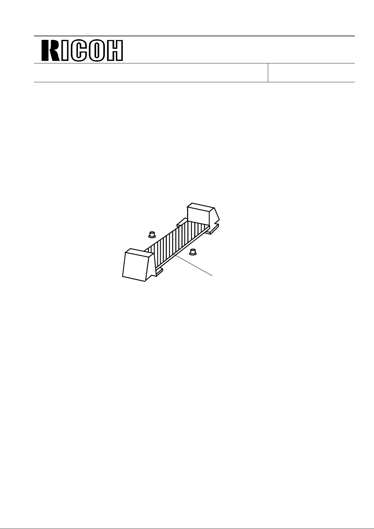
To increase the safety marg in fo r dr op ping, a holder has been added as sho wn
below from July production at th e factory.
DATE:
Aug. 31, 19 95
Holder
Page 18
Page 3/5
Technical Bulletin No. F/L series-006
SUBJECT: Paper size sensor out of posit ion
< Attachment >
DATE:
Aug. 31, 19 95
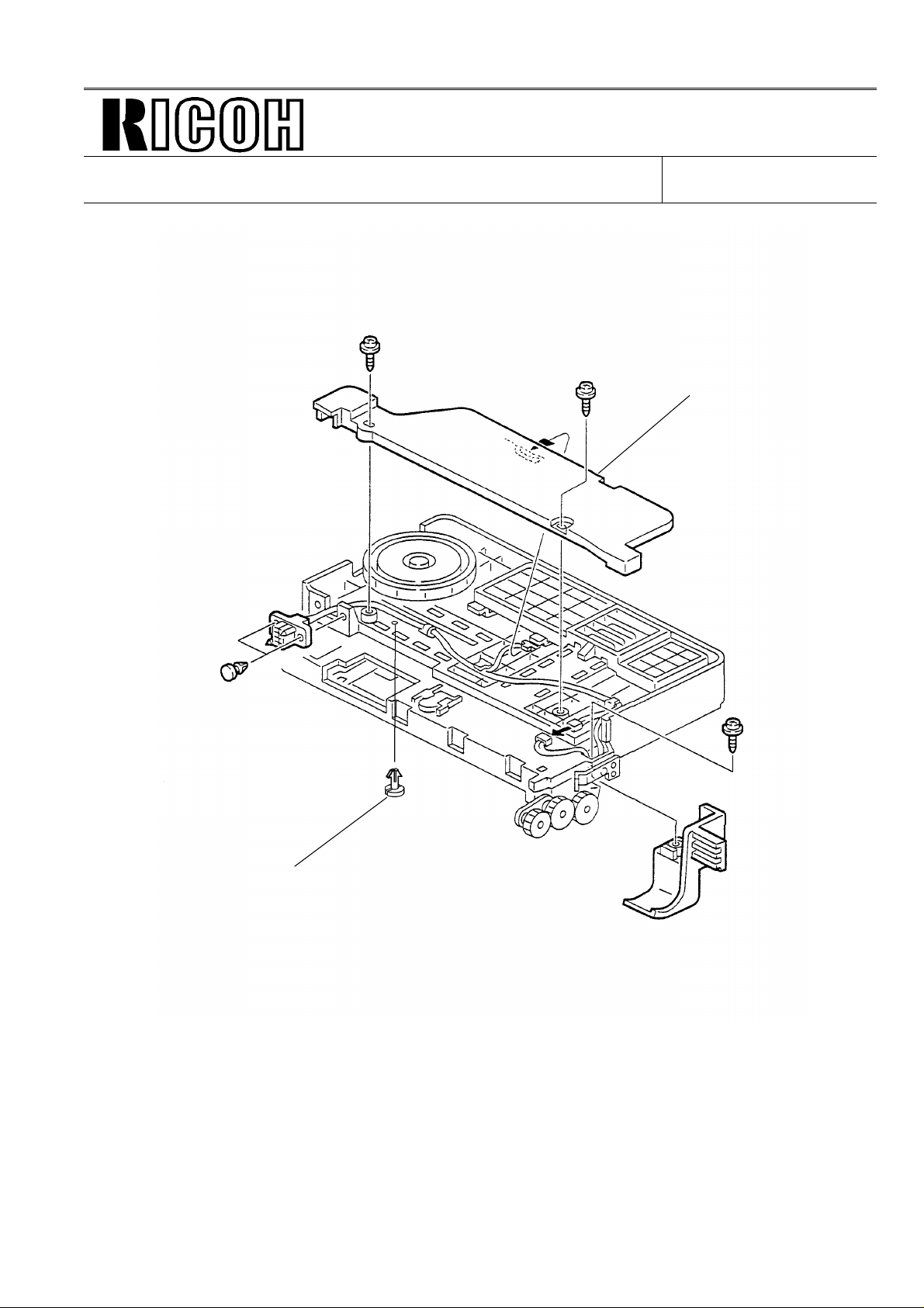
Harness cover
Paper guide stopper
1. Remove the two screws and take off the harn ess cover.
2. Remove the paper guid e sto pp er.
Page 19
Page 4/5
Technical Bulletin No. F/L series-006
SUBJECT: Paper size sensor out of posit ion
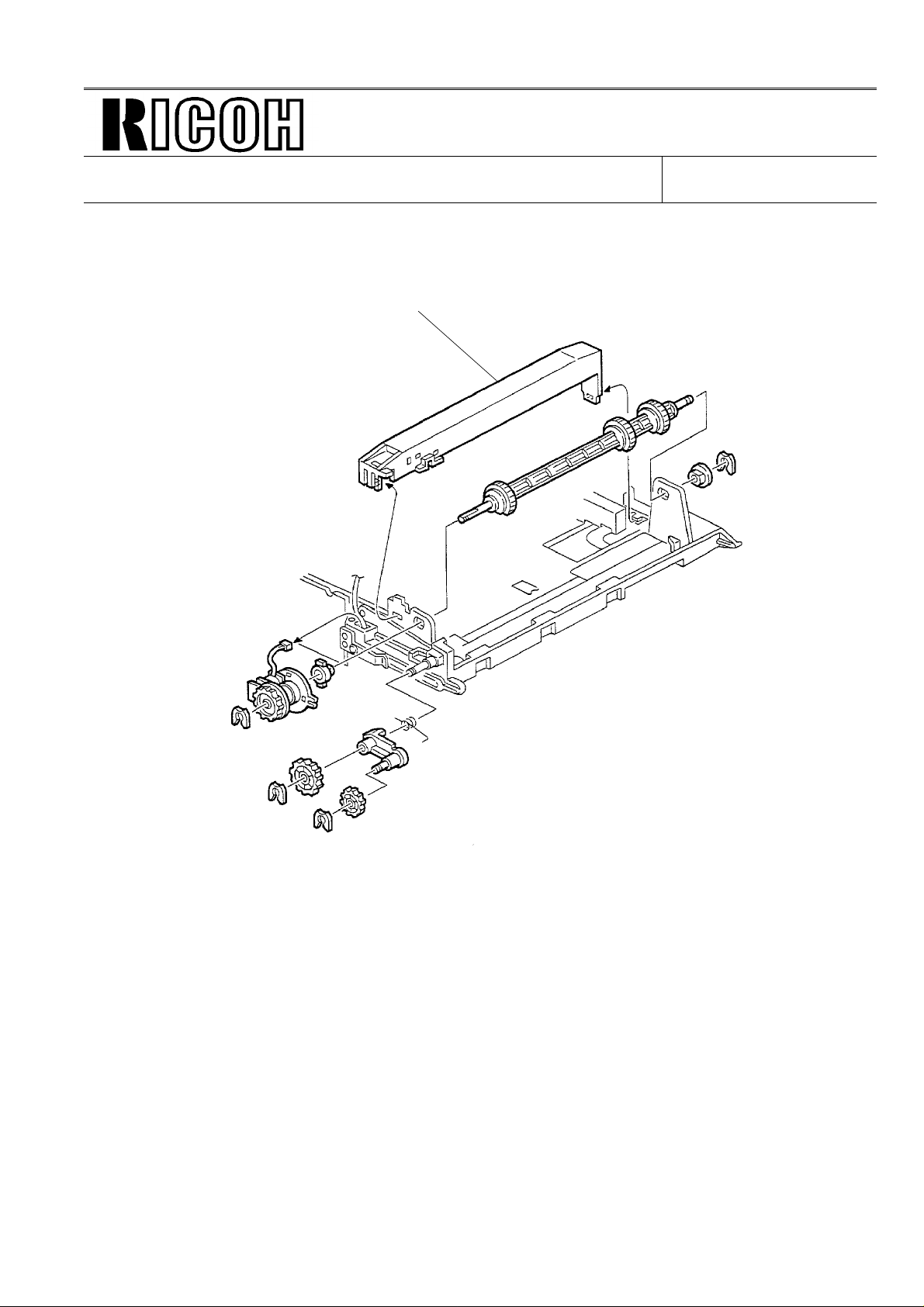
Sensor stay
DATE:
Aug. 31, 19 95
3. Remove the sensor stay.
Page 20
[B]
Page 5/5
Technical Bulletin No. F/L series-006
SUBJECT: Paper size sensor out of posit ion
DATE:
Aug. 31, 19 95
[4]
[A]
[5]
Clip
A: Paper Guide
B: Bottom Plate (2 springs)
C: Paper Size Indicator (1 clip, 1
spring)
4. Remove the paper guide.
5. Remove the bottom plate.
6. Take off the clip and remo ve th e pa pe r size in dica tor.
7. Reinstall the paper size sensor.
Paper size sensor
Page 21
5V
Technical Bulletin No. F/L Series-007
SUBJECT: Auto Service Call 0-05
DATE:
Sep. 15, 19 95
PREPARED BY: Y. Okunishi
CHECKED BY: M. Iwasa
CLASSIFICATION:
Action Required Revision of service manual
FROM: 2nd T.S. Section
MODEL:
FX6
Troubleshooting Information only
Retrofit Information Other
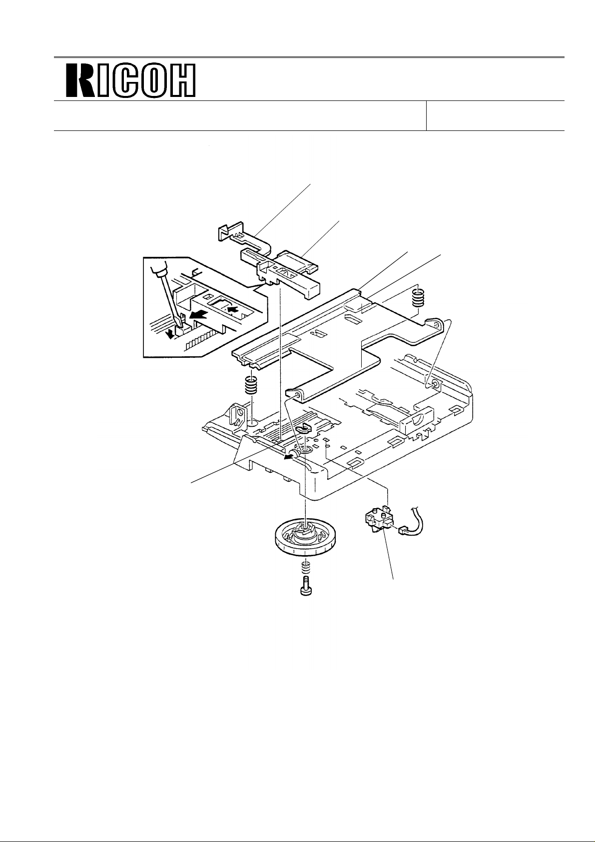
Problem:
Auto Service Call 0-05 (Fusing Unit Failure; see page 6-26 of the Service Man ual )
Cause:
There are two switches, for the 5V line and th e 24V line , in th e Safe ty Switch (Index no.133
on page 1-16 of Parts Catalog). If the Top Cover or Front Cover is not closed completely,
there is a possibility that the 5V switch will turn on but the 24V switch will not.
In this case, "Cover Closed" is detected but the fusing lamp is n ot turn ed on, and this is the
cause of the Auto Service Call.
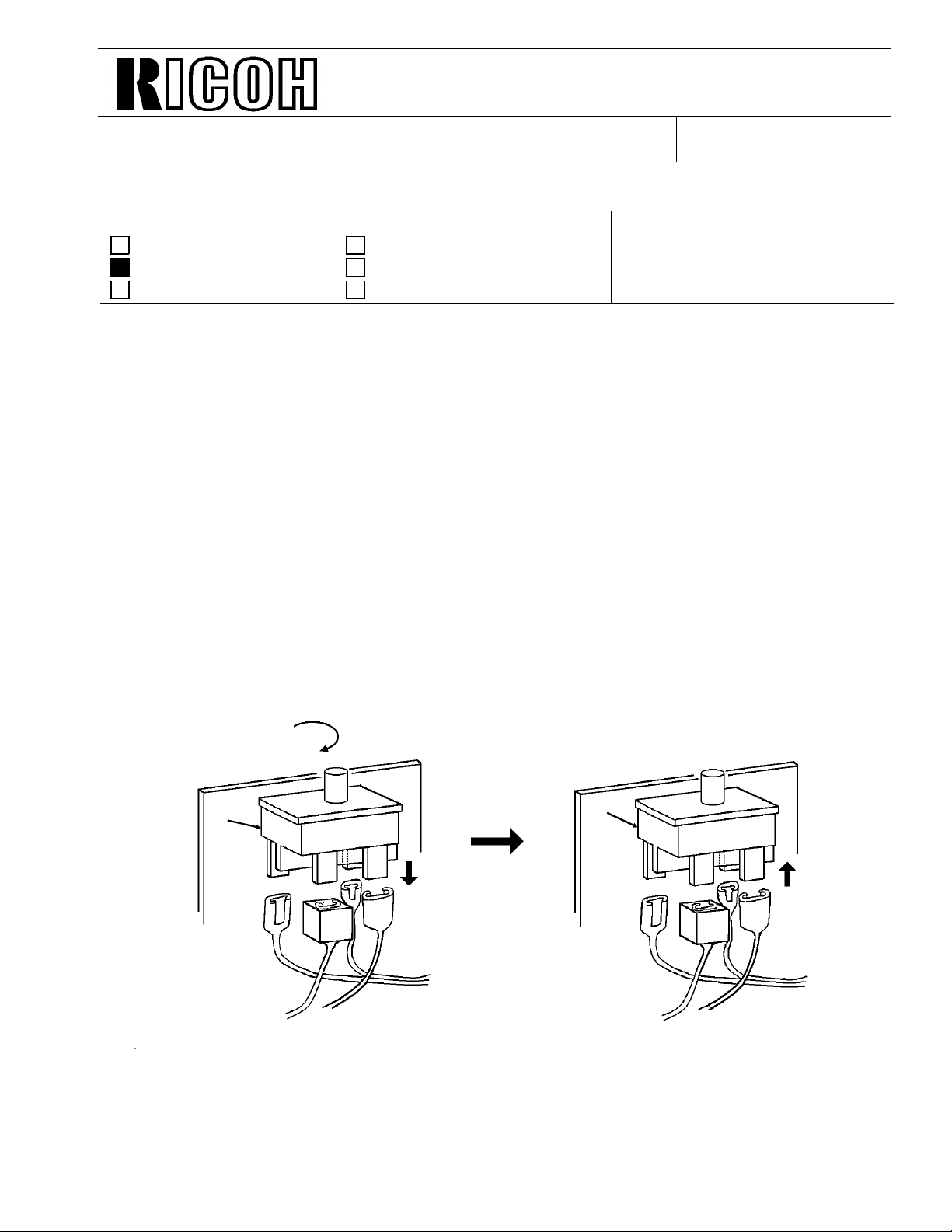
Action Taken:
1) Remove the Right Cover.
2) Disconnect the 5V lines and th e 24 V lines.
3) Remove the Safety Switch.
4) Turn the Safety Switch 180 degrees.
5) Connect the 5V lines and 24 V line s.
B
A
24V
5V
A
B
Note:
RAM reset is required to escape from the Au to Service Call.
For the production:
A modification will be implemen te d to tu rn on th e 24 V line and 5V line at th e same time.
24V
Page 22

Technical Bulletin No. F/L Series-008
SUBJECT: Service Manual Correction
PREPARED BY: Y. Okunishi
CHECKED BY: M. Iwasa
CLASSIFICATION:
Action Required Revision of service manual
Troubleshooting Information only
Retrofit Information Other
The PM table in the service manual has been correct ed .
See the attached sheet.
FROM: 2nd T.S. Section
DATE:
Sep. 15, 19 95
MODEL:
FX6
Page 23
SERVICE TABLES AND PROCEDURES
F/L Series-008
SPECIAL TOOLS AND LUBRICANTS
April 7th, 1995
4.6 SPECIAL TOOLS AND LUBRICANTS
• Flash/SRAM data copy harness (P/N: H5159100)
4.7 PM RABLE
Scanner
Item 30K 60K 90K 1 year Notes
Exposure Glass C(user) C(user) C(user) C(user) Soft cloth and
alcohol
R1 and R2 Rollers C(user) C(user) C(user) C(user) Soft cloth and
alcohol
White Plate C(user) C(user) C(user) C(user) Soft cloth and water
ADF Roller Assy R(user) R(user) R(user) C(user) Soft cloth and water
Separation Pad R(user) R(user) R(user) C(user) Soft cloth and water
Printer
Item 30K 60K 90K 1 year Notes
Paper Feed Roller (*) C Soft cloth and water
Registration Roller C(user) C(user) Soft cloth and alcohol
Thermistor R
Hot Roller Strippers R
Pressure Roller
(Fusing)
Cleaning Pad R(user)
Replaced when a new CTM (toner
Transfer Roller (*) R Dry paper
Development Unit R
100 Sheet Cassette (Optional)
R
A cleaning pad is
enclosed in the CTM.
cassette) is installed.
Item 30K 60K 90K 1 year Notes
Feed Roller (*) C(user) Soft cloth and water
C: Clean, R: Replace
* : Corrected
4-84
Page 24

Page 1/1
Re-issued on: Nov. 15, 1995
Technical Bulletin No. F/L Series-009
SUBJECT: Dedicated Tx Parameters
PREPARED BY: Y. Okunishi
CHECKED BY: M. Iwasa
FROM: 2nd T.S. Section
CLASSIFICATION:
Action Required Revision of service manual
Troubleshooting Information only
Retrofit Information Other
RAM Addresses for Dedicated Tx Parameters
Quick Dials
01: 807166
02: 80716A
4 bytes
03: 80716E
I
I
I
I
32: 8071E2
DATE:
Sep. 15, 19 95
MODEL:
FX6, FX6MΙΙ, FX6CD
Speed Dials
00: 8071E6
01: 8071EA
02: 8071EE
89: 80734A
4 bytes
I
I
I
I
Page 25
Technical Bulletin No. F/L Series - 010
SUBJECT: New Model FAX FX6MkII (FAX 3700L)
PREPARED BY: K. Misugi
CHECKED BY: M. Iwasa
CLASSIFICATION:
Action Required Revision of service manual
Troubleshooting Information only
Retrofit Information Other
The new model FX6MkII (FAX 3700L) has been released in the line-up of the FX6 (FAX 2700L)
series.
This technical bulletin contains informat ion on dif ferences between the FX6MkI I an d the FX6.
They are listed in order of section s tha t appe ar in th e service manual.
FROM: 2nd T.S. Section
MODEL:
DATE:
1995. 9. 14
FAX 3700L
RC Only
1. OVERALL MACHINE INFORMATION
1.1. SPECIFICATIONS
FX6 FX6MkII
Maximum Scan Width 216 mm [8.5 ins] ± 0.25% 256 mm [10.0 ins] ± 0.25%
SAF 244 kbytes
(19 pages/Slerexe letter)
Modulation
Data Rate (bps)
Transmission Time 9 s at 9600 bps;
Paper Size and
Capacity
V.29, V27ter, V21
9600/7200/4800/2400
(Measured with G3 ECM
using memory for a ITU-T #1
test document at stand ard
resolution)
Not Available
(38 pages/Slerexe letter)
(Measured with G3 ECM using
memory for a ITU-T #1 test
document at standard resolution)
Paper Feed Unit (Optional):
500 sheets, available paper size
Europe: A4, A5 sideways
Asia: A4, A5 sideways, F/F4
512 kbytes
V.33/V.17 (TCM),
V.29, V.27 ter, V21
14,400/12,000/
9600/7200/4800/2400
6 s at 14,400 bps;
USA: Letter, Legal
Page 26

Technical Bulletin No. F/L Series - 010
SUBJECT: New Model FAX FX6MkII (FAX 3700L)
1.2. FEATURES
Sub-Title Item FX6 FX6MkII
Equipment Optional paper feed unit Not available Available
Video
Processing
Features
Communication
Features
Other User
Features
1.4. OVERALL MACHINE CONTROL (Please re fe r t o pa ge 4.)
Reduction (B4 to A4)
Not available Available
AI Redial
(last ten numbers)
Telephone Directory Not available Available
Two in one Not available Available
Continuous Polling Not available Available
Checkered mark
Reception time printing Not available Available
Not available Available
Not available Available
DATE:
1995. 9. 14
1.5. VIDEO DATA PATH (Please refer to page 5 and 6.)
1.6. POWER DISTRIBUTION DIAGRAM (P lea se refer to page 7.)
2. DETAILED SECTION DE SCRIPTIONS
2.1. Scanner
2.1.1. Mechanisms
3. Drive Mechanism: The actual scan width for FX6MkII is 256 mm (10.1").
4. Image Scanning: The nu mber of photosensitive elements in the image sensor is 204 8.
2.2. PRINTING
2.2.7. Paper Feed
5. Drive Mechanism
Paper Feed Priority
If all the cassettes con ta in pa pe r of the same size, the machine uses the paper in the optional
paper feed unit first, the paper in the standard cassette second, and the paper in the op tio na l
100 sheet cassette last. Howe ver, this order can be changed with printer bit switch 02 bit 0.
(Please refer to the bit switch section in this bulle tin.)
Page 27

Technical Bulletin No. F/L Series - 010
SUBJECT: New Model FAX FX6MkII (FAX 3700L)
2.2.8. Registration
Jam Detection
New error codes have been added for the optio na l pap er fe ed unit (5 00 shee ts).
Condition Error Code
When the
optional paper
feed unit is used
2.2.11. Fusing
The fusing (printing ) t emp erature is 185 °C.
The printing start te mperature is 160 °C.
2.2.13. Paper Size Selection
When the relay sensor in the paper f eed unit is n ot
turned on within 2.0 seco nd s aft er the paper feed clutch
is enabled .
When the registration sensor in the fax machine is not
turned on within 2.0 seco nd s aft er the paper feed motor
started.
DATE:
1995. 9. 14
9-50
9-51
Same as the previous page for the Paper Feed Priorit y.
2.4. PCBs
2.4.1. FCE2 (Please refer to page 8.)
2.4.2. FDU (Please refer to page 9.)
4. SERVICE TABLES AND PROCEDURES
Please see the attach ment for section 4.
The settings and the switches that are dif fe ren t from the FX6 are shaded.
Page 28
Technical Bulletin No. F/L Series - 010
SUBJECT: New Model FAX FX6MkII (FAX 3700L)
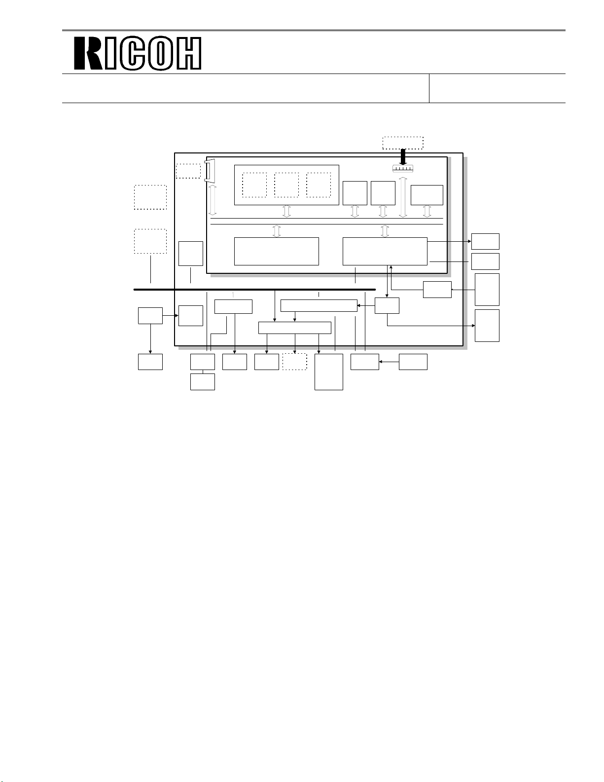
1.4.OVERALL MACHINE CONTROL
Optional
100 Sheet
Cassette
Optional
Printer I/F
PSU
Fusing
Lamp
Optional
IC Card
FDU
Energy
Saver
CPU
DC-DC
Converter
Handset
FCE2
Hybrid IC
Working
Control Signals
(HIC)
SpeakerNCU
RAM
R144EFXL
Modem
Power
Pack
DRAM
ECM/SAF
Memory
DATA/ADDRESS BUS
External I/O (EXIO)
Driver
Optional
Counter
Page
Memory
components
Scanner
sensors
and
printer
and
System
ROM
(Flash)
Operation
Panel
System
RAM
(SRAM)
FCIP
Drivers
(FPD)
Optional
RS232C I/F
Sensors
Video
SRAM
Amplifier
DATE:
1995. 9. 14
LDDR
Thermistor
Contact
Image
Sensor
Tx
and
paper
feed
motors
H516V506.wmf
The FCE2 (Facsimile Control Engine) conta ins the FCIP (Facsimile Control and Image
Processor), DRAM, SRAM, System ROM, R14 4E FXL mode m, and vide o processing
memory, and controls the entire syste m through the FDU (Facs im il e Dri ver Unit).
There are two cpus in the mach ine: the main cpu (FCIP) on the FCE an d the energy saver cpu
on the FDU. In energy saver mode, th e main CPU swit che s off and the energy save r CP U take s
over.
The FCIP consists of the fo llowing component blocks:
• RU8 CPU - Main CPU • MDM - Modem
• LIF- Laser Interface • DMAC - DMA Controller
• PRIF - Printer Interface • DIP - Digital Image Processor
• DCR - Data Compression and Reconstruct ion
The modem inside the FCIP is used for V.29, V27.te r, and V.21 com muni ca tions . In
addition, the Rockwell R144 EFX L modem is used for V.17 and V.33 communications.
The 1.5 MB DRAM contains the SAF memory, ECM buffer memor y, work area, and page
memory. The SAF memory can be extended by 2 or 4 Mbytes with an IC car d.
A 512 kB (4 Mbit) flash ROM is used for the system ROM. Software in this ROM can be
rewritten from the IC card slot or by RDS. Another 128 kB mask ROM contai ns LCD
wording data.
Page 29
Technical Bulletin No. F/L Series - 010
SUBJECT: New Model FAX FX6MkII (FAX 3700L)
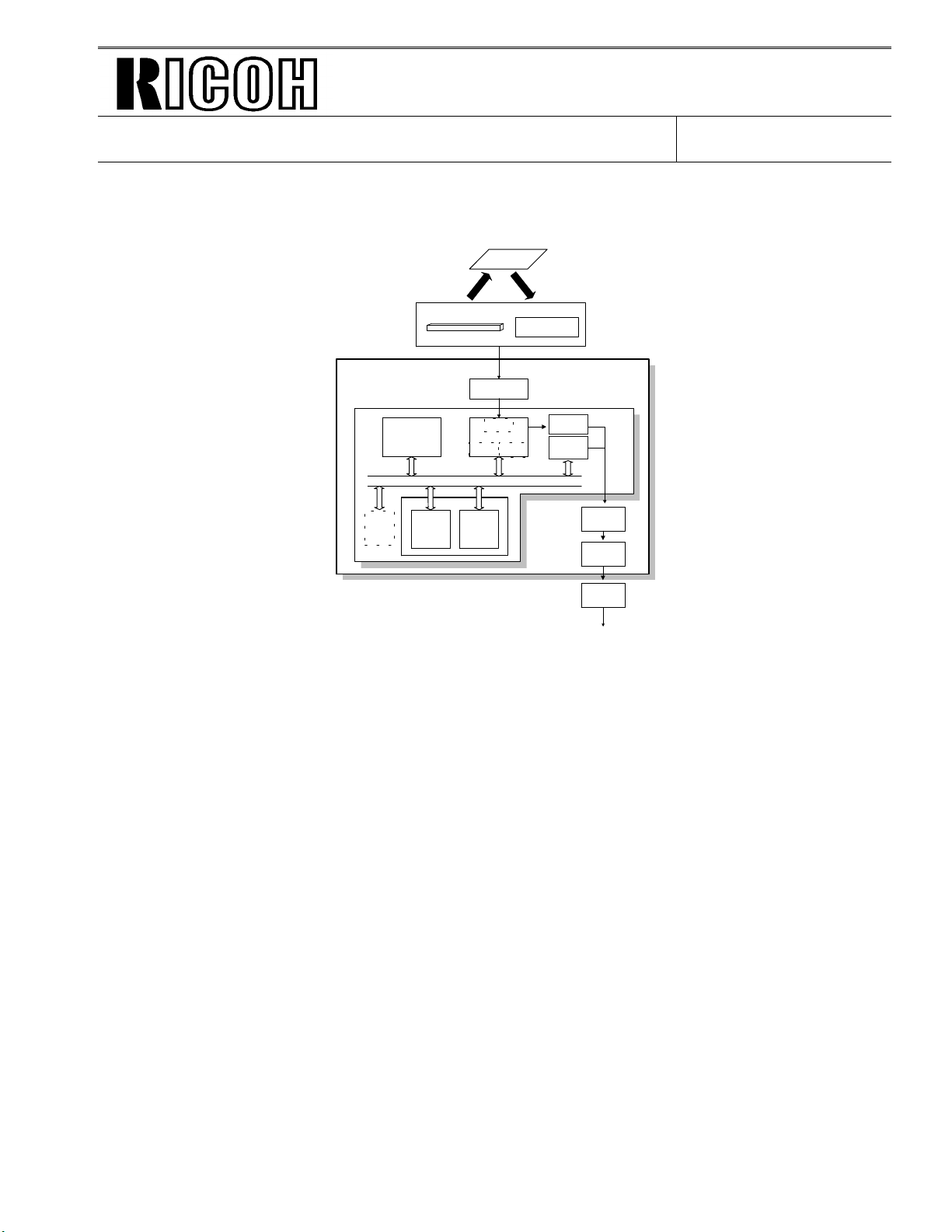
1.5.VIDEO DATA PATH
1.5.1. Transmis sion
Original
Contact Image Sensor
Assembly
LED Array
Amplifier
FCIP
DCR
DATA/ADDRESS BUS
ECM/
SAF
Memory
DIP
MDM
SAF IC
Card
Video
Processing
Memory
DRAM
Line
Buffer
/FIFO
Memory
Image Sensor
E144EFL
Amp
Modem
DATE:
1995. 9. 14
FDU
FCE
Attenuator
HIC
NCU
To the network
H516V507.wmf
DIP: Digital Image Processor
DCR: Data Compression & Reconstruction
MDM: Modem
Immediate Transmission:
Scanned data from the contact imag e sen sor pa sses to the DI P blo ck in the FCIP. Aft er
analog/digital vide o pro cessin g, the DCR block compresses the data for tra nsmission. The
compressed data then passe s eith er to the FIFO memo ry o r to th e ECM memo ry b ef ore it is
sent to the telephone line through the modem. If a data rate of 12,000 or 14,400 bps is used,
the data passes through the E14 4E FL Mod em.
Memory Transmission:
First, the scanned data is sto red in the SAF memo ry aft er compression in the DCR block.
At the time for transmission, the DCR block decompre sses th e data from the SAF me mory, then
compresses it again after ha nd sha king with the other termin al is don e. The compressed data
then passes either to the FIFO memory or to the ECM memory, before it is sent to the
telephone line t hro ug h the modem.
Page 30
Technical Bulletin No. F/L Series - 010
SUBJECT: New Model FAX FX6MkII (FAX 3700L)
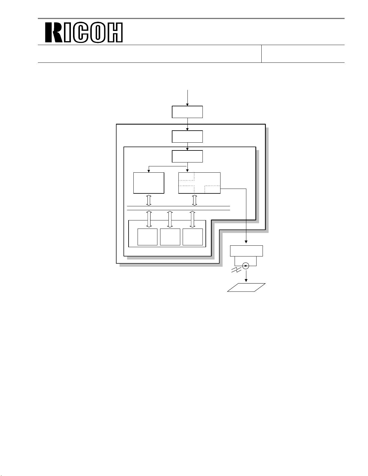
1.5.2. Reception
From the Network
NCU
HIC
Amplifier
E144EFXL
DRAM
Line Buffer
Modem
/FIFO
Memory
DATA/ADDRESS BUS
ECM/SAF
Memory
MDM
FCIP
DCR LIF
Page
Memory
DATE:
1995. 9. 14
LDDR
LIF: Laser Interface
DCR: Data Compression & Reconstruction
MDM: Modem
Copy Paper
H516V508.wmf
Data from the line passe s to th e modem through the NCU and hyb rid IC. Aft er the modem
demodulates the da ta , the decompressed data passe s to th e DCR b lock, through either the
FIFO or the ECM memory, where th e da ta is decompressed to raster image dat a. At the same
time, the compressed data passes to the SAF memo ry as a backu p in case of mech an ical
problems during printing (substitute reception).
The raster image data is th en passe d to the pag e memo ry f or prin ting. After a page of data has
been stored in the page memory, the data is sent to the LDDR thro ug h the LIF block.
Page 31

Technical Bulletin No. F/L Series - 010
SUBJECT: New Model FAX FX6MkII (FAX 3700L)
1.6. POWER DISTRI BUTION
1.6.1. Distribution Diagram
+24VD
-5V
Optional 100
+5VBAT
Sheet
Cassette
12VP
+5V
+5VE
+5vv
+5VLD
+24VM
+5V
AC Switching
Circuit
Fusing Lamp
ON/OFF
Circuit
AC115V or 230V
Fusing
Lamp
AC
Main
Power
Main Switch
PSU
24VIN
Card
+24VM
+24VD
IC
+24V
Optional
Counter
+12VP
+5V
+5VD
+12VD
FCE
+5VD
+5V
DC-DC
Converter
DC-DC
Converter
Fusing Unit
Interlock
Switches
+5VLD
LDDR
Printer
I/F
DC-DC
Converter
+24V
NCU
+5VD
+5VE
+24V
+5V
RS232C
I/F
+5V
FDU
+24VM
+5V
+5VV
-5V
Image Sensor
+24VM
LED Array
+24VM
+24VM
+24VD
+24VD
+24VD
+24VD
+5V
+5V
+5V
+5VE
+5V
DATE:
1995. 9. 14
Optional PFU
Motors
Feed Clutch
Stamp
Cooling Fan
Ozone Fan
Power Pack
Thermistor
Printer Sensors
Operation Panel
+5VE
Scanner Sensors
H516V511.wmf
The PSU supplies +24V dc power to the FDU. The FDU conve rts th e +24 V dc po wer sup ply to
the following supplies.
+5V This is normally on when the main switch is on.
+5VE This is used for detecting an activation signal from the NCU, documen t fe ed er, or
operation panel when the machin e is in energy savin g mod e.
+5VLD This supplies the laser diode. It is interru pt ed if the fusing unit cover interlock
switch opens.
+5VV This is a more stable power supply than +5V. It is use d fo r the Contact Image
Sensor.
+5VD This supplies back up power for the DRAM and th e op tio na l IC card on the FCE .
It can back up stored data for one hour aft er th e power is switched off. A
rechargeable batte ry on th e FDU is use d to gen erate +5VD.
+5VBAT This supplies back up power to the system RAM on the FCE to back up the
programmed data. A lithium batt ery is used to generate +5VBAT.
+24V This is normally on when the main switch is on.
+24VD This is interrupted if the fusing unit cover int erlo ck swit ch open s.
+24VIN This supplies +24V to the fusing unit on/off switching circu it. It is interru pted if the
fusing unit cover interlock switch op en s.
+24VM This is interrupted if the machine enters en erg y saving mode.
-5V This is used for the imag e sen sor.
+12VP This is su pp lied to th e Flash ROMs on the FCE and the optio na l IC ca rd.
Page 32

Technical Bulletin No. F/L Series - 010
SUBJECT: New Model FAX FX6MkII (FAX 3700L)
2.4. PCBs
2.4.1. FCE2
+12VP +5V
Flash ROM
(512kB)
R144EFXL
Modem
DRAM
(1.5MB)
DATA/ADDRESS BUS
29.952MHz
32.768kHz
Video SRAM
(8kB)
FCIP
Mask ROM
(128kB)
SRAM
(32kB)
DATE:
1995. 9. 14
FCE
+5V
IC6
+5VBAT
Battery
Parallel IO
Memory Card (Optional)
RS232C Interface (Optional)
FDU
1. FCIP (Facsimile Controlle r and Im age Processor)
• CPU
• Modem (V.29, V. 27, V.21)
• Data compression and reconstruction (DCR)
• Digital image processor (DIP)
• Laser interface (LIF)
• DMA controller
• Clock generation
• Stepper motor control
• Serial interface to the FDU
• DRAM backup control
• Ringing signal/Tone detection
• Fusing lamp control
Serial IO
H516D530.wmf
Page 33

Technical Bulletin No. F/L Series - 010
SUBJECT: New Model FAX FX6MkII (FAX 3700L)
DATE:
1995. 9. 14
2. Modem (Rockwell R144EFXL)
• V.17, V.33 modem
3. ROM
• 512 kB (4 Mbit) flash ROM for system software stora ge .
• 128 kB (1 Mbit) mask ROM for LCD wording data storage (not used in the US model)
4. DRAM
• 1.5 MB DRAM shared between the Line Buffer (32 kB), ECM Bu ff er (128 kB), Page Memory
(768 kB), and SAF memory (512 kB).
• 5. Backed up by the battery on the FDU.
5. SRAM
• 32 kB SRAM for system and user parameter storage.
• Backed up by the battery on the FCE.
6. Video SRAM
• 8 kB SRAM for video processing.
7. Oscillators
• 29.952 MHz oscillator for system clock generation.
• 32.768 MHz oscillator for the real time clock. This is backed up by th e ba tt ery on the FCE.
• 38.00053 MHz oscillator for the R144EFXL modem.
8. Jumpers, Switche s, and Test Poi nts
Item Description
SW1 Switches the backup battery ON/ OFF
Page 34

Technical Bulletin No. F/L Series - 010
SUBJECT: New Model FAX FX6MkII (FAX 3700L)
2.4.2. FDU
FCE
M
M
Fusing
Lamp
PSU
AC Input
Video I/F
TX Motor
Paper Feed Motor
+24V
Control
MFPD
+24VD
ON/OFF
Converter
Converter
DC/DC
DC/DC
+24VM
ON/OFF
Power Saver
Flash ROM
Boot Block
Overwrite
ON/OFF
+12VP
TB1
+5VE +5V
Printer
I/F
Interlock Switch (+24V)
Serial I/F
CPU
+5V
+5VV
TX DATA
RX DATA
HIC
+5V +5VLD
Serial I/F
External IO
DATE:
TX/RX DATA
1995. 9. 14
Clutches
Solenoids
M
CL
SOL
Sensors
OPU
Optional
PFU
NCU
Main Motor
Serial I/F
Interlock Switch
(+5V)
1. Power Saver CPU
• 4 bit CPU for controlling the machine during powe r sa ver mod e.
2. FPD (Facsimile Powe r Dri ve r)
• Stepper motor driver.
3. EXIO (External I/O)
• Serial interface to the FCE and OPU.
• Serial interface to an optional paper feed unit.
• Parallel interface to the main motor, clutches, and sensors.
4. HIC (Hybrid IC)
• 2-4 wire switching
• Filters and amplifiers
• Monitor speaker driver
5. DC/DC Converters
• +5V generation
+12V generation
H516D531.wmf
Page 35

Technical Bulletin No. F/L Series - 010
SUBJECT: New Model FAX FX6MkII (FAX 3700L)
The following parts for the FX6MkII are different from the FX6.
Index F16 F16mkII Description
3-2 H5164040 H5264040 Cover - PIF
3-3 H5164045 H5264045 Cover - Rear - 2
3-9 H5212041 H5152040 Laser Unit
3-10 H5166002 H5266002 PCB - FCE - FX6MkII - US
3-11 H5166043 H5266003 PCB - FDU - FX6MkII - US
3-* H5168600 H52 68 600 Operator’s Man ual - FX6 MkII - US
7-2 H5164225 H5264291 Cover - Operation Panel - FX6MkI I
7-24 H5164303 H5264309 Quick Dial Sheet - US
9-15 H5161066 H5261066 Contact Image Senso r - B4
9-19 H5161062 Not used Spacer - Image Sensor
11-12 H5215061 H5155040 Polygonal Motor - DC24V; 0.35A
19-2 H5163342 H5263391 Base - Main Board
21-5 H5163407 H5163401 Cassette Base - Universal
21-42 H5163465 H5153465 Suppo rt Plate - End Fence
H5155318 PFU Harness
H5163430 Paper Size Detecto r - LG
H5153466 Plastic Rivet (Cassette End Fence)
18-36* H5153693 Positioning Pin
H5164088 Cassette Cover
2-42* H5263395 Spacer - FCE - Front
2-43* H5263396 Spacer - FCE - Rear
DATE:
1995. 9. 14
Note: * Please see the next page for the loca tion of the parts.
Page 36

Technical Bulletin No. F/L Series - 010
SUBJECT: New Model FAX FX6MkII (FAX 3700L)
DATE:
1995. 9. 14
Page 37

August 2nd, 1995 SERVICE TABLES AND PROCEDURES
SERVICE LEVEL FUNCTIONS
4. SERVICE TABLES AND PROCEDURES
4.1. SERV ICE LEVEL FUNCTIONS
In this section, frequently used keys are referred to with the following
symbols.
S
- Start key
FU
- Function key
Y
- Yes key
^
- Up arrow key
>
- Right arrow key
4.1.1. Bit Switch Programming (Function 01)
s
- Stop key
N
- No key
_
- Down arrow key
<
- Left arrow key
1. FU 6 1 9 9 5
then immediately Y
2. 0 1 Y
Bit 7 is displayed at the lef t, and bit 0 at
the right.
3. Scroll through the bit switch menu: * or
#
Example: To see the communication
switches : # × 3
Then scroll through the bit switches.
Increment bit switch: >
Decrement bit switch: <
Example: Display bit switch 3: > x 3
4. Adjust the bit switch.
Example: To change the value o f bit 7,
FUNCTION KPAD/NEXT
SERVICE FUNCTIONS
SYS DF : 0000 0000
BITSW 00: 0000 0000
COM DF : 0000 0000
BITSW 00: 0000 0000
COM DF : 0000 0000
BITSW 03: 1000 0000
press 7
5. Either:
• Adjust more bit switches - go to step 3.
• Finish - FU
4-1
Page 38

SERVICE TABLES AND PROCEDURES August 2nd, 1995
SERVICE LEVEL FUNCTIONS
4.1.2. System Parameter List (Function 02)
The format of the list is as follows.
* * * SYSTEM PARAMETER LIST (Date and Time) * * *
SERIAL NO. - Serial number programmed by function 14)
ROM VER. [Version] [Software release no.] [Software release date]
ROM NO. [Software part no.] [Check sum values (total) (boot) (main)]
R T I
T T I
C S I
ID CODE
MEMORY LOCK ID
NUMBER
OWN NUMBER
SERVICE NUMBER
NCU PARAMETER
COUNTER
PARAMETER
SCAN THRESHOLD
2MB or 4MB - Optional memory card capacity installed
CASSETTE 2 - Optional paper feed unit installed
SWITCH (UPPER:DEFAULT LOWER:CURRENT)
(SWUSR) - User Parameter Settings
CONFIDENTIAL ID
TTI
SWITCH (UPPER:DEFAULT LOWER:CURRENT)
(SWSYS) - System Bit Switch Settings
(SWSCN) - Scanner Bit Switch Settings
(SWPLT) - Printer Bit Switch Settings
(SWCOM) - Communication Bit Switch Settings
(SWG3) - G3 Bit Switch Settings
1. FU 6 1 9 9 5
then immediately Y
2. 0 2 Y S
H526M510.wmf
FUNCTION KPAD/NEXT
SERVICE FUNCTIONS
3. Finish: FU
4-2
Page 39

August 2nd, 1995 SERVICE TABLES AND PROCEDURES
SERVICE LEVEL FUNCTIONS
4.1.3. Error Code Display (Function 03)
1. FU 6 1 9 9 5 ,
then immediately Y
2. 0 3 Y
3. Either:
Scroll through the error code s - > or <
Finish - FU
4.1.4. Service Monitor Report (Function 04)
1. FU 6 1 9 9 5
then immediately Y
2. 0 4 Y S
FUNCTION KPAD/NEXT
SERVICE FUNCTIONS
ERROR CODE < >
1-01 JAN 01 17:30
FUNCTION KPAD/NEXT
SERVICE FUNCTIONS
3. Finish: FU
4-3
Page 40

SERVICE TABLES AND PROCEDURES August 2nd, 1995
SERVICE LEVEL FUNCTIONS
4.1.5. Protocol Dump (Function 05)
1. FU 6 1 9 9 5
then immediately Y
2. 0 5 Y
3. S
4. Finish: FU
4.1.6. RAM Display/Rewrite (Function 06)
1. FU 6 1 9 9 5
then immediately Y
2. 0 6 Y
FUNCTION KPAD/NEXT
SERVICE FUNCTIONS
START
PROTOCOL DUMP
FUNCTION KPAD/NEXT
SERVICE FUNCTIONS
0-MEM.R/W 1-MEM.DUMP
3. 0
4. Input the address that you wish to see.
Example: A ddress 800020
8 0 0 0 2 0
Note: If you wish to move the cursor,
press > .
5. If you wish to change the data, type in
the new data.
Example: 80, press 8 0
Note: If you wish to move the cursor,
press > .
6. Either:
• View more addresses - go to step 4.
• Finish - FU
ADDRESS = 000000
DATA = 00
ADDRESS = 800020
DATA = 20
ADDRESS = 800020
DATA = 80
4-4
Page 41

August 2nd, 1995 SERVICE TABLES AND PROCEDURES
SERVICE LEVEL FUNCTIONS
4.1.7. RAM Dump (Function 06)
1. FU 6 1 9 9 5
then immediately Y
2. 0 6 Y
3. 1
4. Enter the first four digit s of th e start an d
end addresses . For example, en te r
“8000” for start address 800000(H), and
enter 8001 for end address 8001FF(H).
Then, press "Start" to print the dump list.
Example: Start at 800000, end at 8001FF.
80008001S .
5. Finish: FU
FUNCTION KPAD/NEXT
SERVICE FUNCTIONS
0-MEM.R/W 1-MEM.DUMP
MEMORY DUMP START/N
ADD.000000 - 0000FF
MEMORY DUMP START/N
ADD. 800000- 8001FF
MEMORY DUMP
4.1.8.4.1.8. Counter Display/Rewrite (Function 07)
1. FU 6 1 9 9 5
then immediately Y
2. 0 7 Y
3. Either:
Check the transmitted, received,
scanned and printed pa ge coun te rs, an d
the printer and scanner jam counters -
press 0
FUNCTION KPAD/NEXT
SERVICE FUNCTIONS
0-COUNTER 1-PM
2-CTM 3-OPU
TX: 012345
RX: 012345
4-5
Page 42

SERVICE TABLES AND PROCEDURES August 2nd, 1995
SERVICE LEVEL FUNCTIONS
(To see the scanned and printed
page counters, press #.
To see the printer and scann er jam cou nt -
ers, press # again.)
Check the PM counter - press 1
Check the CTM counter - press 2
Check the OPU counte r - press 3
4. To change the contents of a counter,
input the new value, then press Y .
5. To finish: FU
SCAN : 012345
PRINT : 012345
S.JAM: 000000
P.JAM: 000000
PM COUNTER: 001234
CTM COUNTER: 001234
OPU COUNTER: 001234
4.1.9. NCU Parameters (Function 08)
1. FU 6 1 9 9 5
FUNCTION KPAD/NEXT
SERVICE FUNCTIONS
then immediately Y
2. 0 8 Y
3. 0
4. Scroll through the parameters using
0-NCU 1-MODEM
2-DTMF 3-DETECT
NCU KPAD/<>
NO.04 = 005
> or < . If you want to change a
value, enter the ne w va lue at the keypad,
then press Y .
Example: Set NCU parameter 04 to 005.
>>>> 0 0 5 Y
5. To finish : N FU.
Note: Parameter CC is the Country Code, Parameter 01 is the Tx le vel.
Refer to section 4.3 for full details on NCU parameters.
4-6
Page 43

August 2nd, 1995 SERVICE TABLES AND PROCEDURES
SERVICE LEVEL FUNCTIONS
4.1.10. Modem Test (Function 08)
1. FU 6 1 9 9 5
FUNCTION KPAD/NEXT
SERVICE FUNCTIONS
then immediately Y
2. 0 8 Y
3. 1
0-NCU 1-MODEM
2-DTMF 3-DETECT
MODEM TEST START/< >
800Hz
4. Scroll through the available tests using > or < .
5. S
6. To stop the test: s
7. To finish: N FU
4.1.11. DTMF Tone Test (Function 08)
1. FU 6 1 9 9 5
FUNCTION KPAD/NEXT
SERVICE FUNCTIONS
then immediately Y
2. 0 8 Y
3. 2
0-NCU 1-MODEM
2-DTMF 3-DETECT
DTMF TEST START/<>
TONE 0
4. Scroll through the available tests using > or < .
5. S
6. To stop the test: s
7. To finish: N FU
4-7
Page 44

SERVICE TABLES AND PROCEDURES August 2nd, 1995
SERVICE LEVEL FUNCTIONS
4.1.12. Modem Detection Test (Function 08)
Note: This function can be used only when G3 bit switch 0B bit 5 (French
PTT requirements) is 1 in Euro pean mode ls. It cann ot be used in
USA models.
1. FU 6 1 9 9 5
FUNCTION KPAD/NEXT
SERVICE FUNCTIONS
then immediately Y
2. 0 8 Y
3. 3
0-NCU 1-MODEM
2-DTMF 3-DETECT
MODEM DET START/<>
V21 300BPS
4. Scroll through the available tests using > or <
5. S
6. To stop the test: s
7. To finish: N FU
4.1.13. Ringer Test (Function 08)
1. FU 6 1 9 9 5
then immediately Y
2. 0 8 Y
3. 4
5. S
6. To stop : s
7. To finish: N FU
FUNCTION KPAD/NEXT
SERVICE FUNCTIONS
0-NCU 1-MODEM
2-DTMF 3-DETECT
START
RINGER
4-8
Page 45

August 2nd, 1995 SERVICE TABLES AND PROCEDURES
SERVICE LEVEL FUNCTIONS
4.1.14. Operation Panel Test (Function 09)
1. FU 6 1 9 9 5
then immediately Y
2. 0 9 Y
3. 0
4. S
5. To stop the test, press s
6. To finish: N FU
4.1.15. LED Array Test (Function 10)
1. FU 6 1 9 9 5
then immediately Y
FUNCTION KPAD/NEXT
SERVICE FUNCTIONS
0-LED/LCD
FUNCTION KPAD/NEXT
SERVICE FUNCTIONS
2. 1 0 Y
3. 0
4. S
5. To stop the test, press s
6. To finish: N FU
0-LAMP 1-ADF
START
LAMP 0 0 0
4-9
Page 46

SERVICE TABLES AND PROCEDURES August 2nd, 1995
SERVICE LEVEL FUNCTIONS
4.1.16. ADF Test (Function 10)
1. FU 6 1 9 9 5
then immediately Y
2. 1 0 Y
3. 1
4. Place a document in the feeder,
then press S .
5. To stop the test, press s
6. Finish: N FU
4.1.17. Printer Test Patterns (Function 11)
FUNCTION KPAD/NEXT
SERVICE FUNCTIONS
0-LAMP 1-ADF
START
ADF
1. FU 6 1 9 9 5
then immediately Y
2. 1 1 Y
3. 0
5. Press a key from 0 to 4.
6. Press S .
A test pattern is printed.
7. To finish: N FU
FUNCTION KPAD/NEXT
SERVICE FUNCTIONS
0-PATTERN 1-MECH
PATTERN PRINT KPAD
0-4
4-10
Page 47

August 2nd, 1995 SERVICE TABLES AND PROCEDURES
SERVICE LEVEL FUNCTIONS
4.1.18. Printer Mechanism Test - Free Run (Function 11)
1. FU 6 1 9 9 5
then immediately Y
2. 1 1 Y
3. 1
4. S
5. To stop the test, press s
6. To finish: N FU
4.1.19. RAM Tests (Function 12)
1. FU 6 1 9 9 5
then immediately Y
FUNCTION KPAD/NEXT
9 SERVICE FUNCTIONS
0-PATTERN 1-MECH
START
MECH
FUNCTION KPAD/NEXT
SERVICE FUNCTIONS
2. 1 2 Y
0-SRAM 1-SAF
2-SAFCARD 3-M-->R
3. Either:
Test the SRAM: Press 0 S
Test the SAF: Press 1 S
Test the SAF card: Press 2 S
If test is successful, the disp lay shows "OK".
If test is unsuccessful, the disp lay shows "ADDRESS=".
4. To finish: N FU.
4-11
Page 48

[A]
SERVICE TABLES AND PROCEDURES August 2nd, 1995
SERVICE LEVEL FUNCTIONS
4.1.20. Software Download (Function 12)
Instead of replacing an EPROM to update the mach ine’s software , use this
procedure to update th e software in the machine’s Flash ROM.
This function copies softwa re fro m an ext ernal medium to the Flash ROM on
the machine’s FCE. The external medium for the new software can be an
FCE or an EPROM board.
1. Turn off the mach ine.
Do this only if rewriting
the boot block.
See the note at the end
of this procedure.
[B]
[D]
[C]
H516M501.wmf
2. Insert the Flash/S RAM Cop y Tool [A] into the IC card slo t [ B] , t hen co n-
nect the FCE or EPROM board with new software [C] to the opposite side
of the tool.
Note: The switch [D] on the tool [A] must be at the ON position.
3. Turn o n t he mach ine.
4. FU 6 1 9 9 5
FUNCTION KPAD/NEXT
SERVICE FUNCTIONS
then immediately Y
5. 1 2 Y >
0-SRAM 1-SAF
2-SAFCARD 3-M-->R
6. 4
4-12
Page 49

August 2nd, 1995 SERVICE TABLES AND PROCEDURES
SERVICE LEVEL FUNCTIONS
7. S
If the software is successfully downloaded, the display shows "OK".
OK!!
COPY MACH <- FLROM
If the software download fails, the displa y
shows "NG".
NG!!
COPY MACH <- FLROM
8. To finish, press FU.
9. Turn off the mach ine and disconnect the tool. Then turn the machine back
on.
10. Print out the system paramete r list and check th e ROM versio n on it.
Note: In rare cases, the boot block will have to be rewritten. In such cases,
you must do the following in addition to the above procedure.
• Before step 1, open th e rea r cover an d cha ng e t he jumper at TB1
on the FDU as shown in the diagram on the previous pa ge.
• After step 3, set bit 5 of system switch 02 to 1.
• Before switching on the mach ine again in step 9, put TB1 b ack t o
the default position (pins 2-3 sho rte d).
4.1.21. Software Upload (Function 12)
This function copies the sof tware from the machine’ s bu ilt-in FCE to an exte rnal FCE.
1. Turn off the mach ine.
2. Connect the Flash/SRAM Copy Tool and an FCE as shown in the pre-
vious section.
Note: The switch [D] on the tool must be at th e OFF position.
3. T urn on the machine.
4. FU 6 1 9 9 5
FUNCTION KPAD/NEXT
SERVICE FUNCTIONS
then immediately Y
5. 1 2 Y
0-SRAM 1-SAF
2-SAFCARD 3-M-->R
4-13
Page 50

SERVICE TABLES AND PROCEDURES August 2nd, 1995
SERVICE LEVEL FUNCTIONS
6. 3 S
OK!!
COPY MACH -> FLROM
If the software is successfully uploaded,
the display shows "OK".
If the software upload fails, the display
shows "NG".
NG!!
COPY MACH -> FLROM
7. Finish : FU
8. Turn off the mach ine and disconnect the tool. Then turn the machine back
on again.
4.1.22. SRAM Data Download (Function 12)
This function copies all th e da ta stored in the SRAM on an externa l FCE to
the machine’s FCE. Use this af ter replacing a damaged FCE to save an y previous settings that were programmed in the damage d FCE.
1. Turn o ff the machine.
2. Connect the Flash/SRAM Copy Tool [A] and the damaged FCE [C] as
shown in section 4.1.20.
Note: The setting of switch [D] on the too l will not affect the resu lt of
this procedure.
3. Turn o n t he mach ine.
4. FU 6 1 9 9 5
FUNCTION KPAD/NEXT
SERVICE FUNCTIONS
then immediately Y
5. 1 2 Y >
0-SRAM 1-SAF
2-SAFCARD 3-M-->R
6. 5
7. S
OK!!
COPY MACH <- SRAM
If the SRAM data is successfully down loaded, the display shows "OK".
If the SRAM download fails, the display
shows "NG".
NG!!
COPY MACH <- SRAM
8. Finish : FU
9. Turn off the mach ine and disconnect the tool. Then turn the machine back
on.
4-14
Page 51

August 2nd, 1995 SERVICE TABLES AND PROCEDURES
SERVICE LEVEL FUNCTIONS
4.1.23. Serial Number (Function 14)
1. FU 6 1 9 9 5
FUNCTION KPAD/NEXT
SERVICE FUNCTIONS
then immediately Y
2. 1 4 Y
3. Enter the machine’s serial number a t th e
keypad.
SERIAL # KPAD
SERIAL # KPAD/Y/N
RICOH 1234567
To correct a mistake: N
4. If the display is correct: Y
5. Finish: FU
4.1.24. Service Station Fax Number (Function 13)
1. FU 6 1 9 9 5
FUNCTION KPAD/NEXT
SERVICE FUNCTIONS
then immediately Y
2. 1 3 Y
S.S. NO. KPAD
_
3. Input the telephone number of the service station that will receive Aut o
Service calls from this machine.
To erase the telephone number: press N
S.S. NO. KPAD
2125555242
4. If the display is correct: Y FU
4-15
Page 52

SERVICE TABLES AND PROCEDURES August 2nd, 1995
BIT SWITCHES
4.2. BIT SWITCHES
WARNING
I
Do not adjust a bit switch that is described as "Not used", as this may
cause the machine to malfunction or to operate in a manner that is not
accepted by local regulations. Such bits are for use only in other
areas, such as Japan.
Note: Default settings for bit switch es are not listed in this manual. Refer to
the System Paramete r List prin ted by the machine.
4.2.1. System Switches
System Switch 00
No FUNCTION COMMENTS
RAM Reset
Bit 1 Bit 0 Reset Level
0 0 No reset
0 1 Reset Level 2
1 0 Reset Level 3
1 1 Not used
0
1
Reset Level 3: Erases all image data files stored in
the SAF memory and communciation files (e.g. polling
rx file). This setting is recommended for use when it is
necessary to clear the SAF.
Reset Level 2: In addition to those items erased by
Reset Level 3, the following items are erased: own
telephone number, bit switches, RTI/TTI/CSI, report
data, programmed telephone numbers (Quick/Speed/
Groups, service station, etc.), NCU parameters,
personal codes.
After erasing, the machine changes these two bits
back to 0 automatically.
No reset: Normal operation
Cross reference
RAM Reset Level 1 (Factory reset):
Change the data in RAM address 800000(H) to FF(H),
then turn the machine off and on. In addition to those
items erased by Reset Level 2, the clock and
scan/print registration settings are erased.
4-16
Page 53

August 2nd, 1995 SERVICE TABLES AND PROCEDURES
BIT SWITCHES
System Switch 00
No FUNCTION COMMENTS
Technical data printout on
TCR (Journal)
0: Disabled
1: Enabled
2
Line quality data output
method
0: Measure of error rate
3
(during image data
transmission only)
1: Rx level
Line error marks
0: Disabled
4
1: Enabled
Communication parameter
display
0: Disabled
5
1: Enabled
Protocol dump list output
after each communication
6
0: Off 1: On
Not used Do not change the settings.
7
1: Instead of the personal code, the following data are
listed on the TCR for each analog G3 communication.
e.g. V33 14 01 03 00 02
First number: Final modem type used
Second number: Final modem rate (for example, 14
means 14.4 kbps)
Third and fourth numbers: Line quality data. Either a
measure of the error rate or the rx level is printed,
depending on the bit 3 setting below. (An M on the
report indicates that it is error rate, and an L indicates
Rx level.) The left hand figure is the high byte and the
right hand figure is the low byte (see the note below
this table for how to read this value). If it is a measure
of the error rate; a larger number means more errors.
Fifth number (rx mode only): Total number of error
lines that occurred during non-ECM reception.
Sixth number (rx mode only): Total number of burst
error lines that occurred during non-ECM reception.
The fifth and sixth numbers are fixed at 00 for
transmission records and ECM reception records.
This bit determines the data type to be printed on the
TCR (Journal) when technical data printout is enabled
by bit 2 above.
If this bit is 1, a mark will be printed on the left edge of
the page at any place where a line error occured in the
data. Such errors are caused by a noisy line, for
example.
This is a fault-finding aid. The LCD shows the key
parameters (see the next page). This is normally
disabled because it cancels the CSI display for the
user.
Be sure to reset this bit to 0 after testing.
This is only used for communication troubleshooting. It
shows the content of the transmitted facsimile protocol
signals. Always reset this bit to 0 after finishing testing.
How to calculate the rx level listed on the TCR (when bit 2 of system switch 00 is set to 1)
Example: V29 96 L 01 0C 00 00
The four-digit hexadecimal value (N) after L indicates the rx level. Divide the decimal value of
N by -16 to get the rx level.
In this example, the decimal value of 010C(H) is 268.
So, the actual rx level is 268/16 = -16.75 dB.
4-17
Page 54

SERVICE TABLES AND PROCEDURES August 2nd, 1995
BIT SWITCHES
Communication Parameters
Mode DCS: ITU-T standard NSS: Non-standard G3
Modem rate 144: 14400 bps
120: 12000 bps
96: 9600 bps
72: 7200 bps
48: 4800 bps
24: 2400 bps
Communication
mode
Compression
mode
Resolution SSF: Fine, transmitted at 8 x 15.4 dots per mm
I/O rate 0M: 0 ms/line 10M: 10 ms/line
Width and
reduction
ECM: With ECM SSC: Using SSC
EFC: Using EFC NML: With no ECM, SSC, or EFC
MMR: MMR compression
MR: MR compression
MH: MH compression
DTL: Detail, transmitted at 8 x 7.7 dots per mm
STD: Standard, transmitted at 8 x 3.85 dots per mm
2/M: 2.5 ms/line 20M: 20 ms/line
5M: 5 ms/line 40M: 40 ms/line
=A4: A4 (8.3"), no reduction
=B4: B4 (10.1") no reduction
>A4: Reduced to A4 (8.3") before transmission
System Switch 01
No FUNCTION COMMENTS
PM call
0: Disabled
1: Enabled
0
Not used Do not change the settings.
1-7
This bit switch determines whether the machine will
send an Auto Service Call to the service station when it
is time for PM.
Cross reference
Auto service calls: Section 2.3.2
4-18
Page 55

August 2nd, 1995 SERVICE TABLES AND PROCEDURES
BIT SWITCHES
System Switch 02
No FUNCTION COMMENTS
Memory file transfer
0: Disabled
1: Enabled
0
Programmed data transfer
(Back-to-back)
0: Disabled
1: Enabled
1
Not used Do not change the setting.
2
Memory file printout
0: Disabled
3
1: Enabled
Not used Do not change the settings.
4
Software download area
0: All except the boot block
1: All areas, including the
boot block
5
Keep this bit at 0 except for
the rare cases when the
Flash ROM boot block has
to be rewritten.
Memory read/write by RDS
Bit 7 6 Setting
0 0 Always disabled
0 1 User selectable
6
1 0 User selectable
1 1 Always enabled
7
1: All messages in the memory (including confidential
rx messages) are sent to the fax number which is
programmed as the service station.
Always reset this bit to zero after transfer.
Cross reference
Service station number programming: Function 13
Do the following steps to transfer the data.
1. Connect two machines of the same type back to
back and enable back-to-back communication on both
machines. (For this machine, set bit 7 of the G3 bit
switch 00 to 1.)
2. Set this switch to 1 on the receiving machine.
3. Insert a sheet of paper in the ADF, and press Start
on both machines. The data is transferred.
4. Disable back-to-back comminication and set this bit
to 0 after finishing.
1: All SAF files, including confidential messages, can
be printed using Function 54 or 55.
Always reset this bit after printing the messages.
0: This is the normal setting. For normal software
downloads, do not change this bit switch.
1: Set this bit to 1 only when you need to rewrite the
boot block in the Flash ROM using Function 12.
Cross reference
Software Download: Section 4.1.20
(0,0): All RDS systems are always locked out.
(0,1), (1,0): Normally, RDS systems are locked out, but
the user can temporarily switch RDS on to allow RDS
operations to take place. RDS will automatically be
locked out again after a certain time, which is stored in
System Switch 03 (see below). Note that if an RDS
operation takes place, RDS will not switch off until this
time limit has expired.
(1,1): At any time, an RDS system can access the
machine.
4-19
Page 56

SERVICE TABLES AND PROCEDURES August 2nd, 1995
BIT SWITCHES
System Switch 03
No FUNCTION COMMENTS
Length of time that RDS is
0
temporarily switched on
when bits 6 and 7 of
to
System Switch 02 are set to
7
"User selectable"
System Switch 04
No FUNCTION COMMENTS
LCD contrast
Bit 2 1 0 Contrast
0
0 0 0 Brightest
0 0 1 ↓
1
↓ ↓
2
1 1 0 ↓
1 1 1 Darkest
Dedicated transmission
parameter programming
3
0: Disabled 1: Enabled
Inclusion of the Start key in
Keystroke Programs
4
0: Not needed
1: Needed
OPC (master drum)
replacement level
0: User
1: Service
5
CSI programming level
0: User level
6
1: Service level
Telephone line type
programming mode
7
0: User level
1: Service level
00 - 99 hours (BCD).
This data is only valid if bits 6 and 7 of System Switch
02 are set to "User selectable".
The default setting is 24 hours.
Use these bit switches to adjust the contrast of the
LCD on the operation panel.
This bit must be set to 1 before changing any
dedicated transmission parameters.
0: The user does not need to press the Start key when
operating a keystroke program.
0: The machine asks the user to replace the OPC
drum at 30,000 print intervals (default interval).
After the user replaces the drum, the machine asks the
user if the drum is replaced or not. If the user answers
yes, the machine resets the OPC counter to zero. The
drum replacement interval is programmed at
addresses 8001E5 to 8001E7(H). Refer to section 4.5
for more details.
1: The machine will not ask the user to replace the
drum.
1: The CSI can only be programmed using a service
function.
1: Telephone line type selection can only be
programmed using a service function.
4-20
Page 57

August 2nd, 1995 SERVICE TABLES AND PROCEDURES
BIT SWITCHES
System Switch 05
No FUNCTION COMMENTS
0 Not used Do not change the settings.
1
Display of both RTI and CSI
on the LCD
2
0: Disabled 1: Enabled
Not used Do not change the settings.
3-7
System Switch 06
No FUNCTION COMMENTS
Use of the Stop key during
memory transmission
0
0: Disabled 1: Enabled
Not used Do not change the settings.
1-7
System Switch 07 - Not used (do not change the settings)
System Switch 08 - Not used (do not change the settings)
1: Both RTI and CSI will be displayed alternately on
the LCD.
1: Memory transmissions can be stopped by pressing
the Stop key. However, users might accidentally cancel
another person’s memory transmission in progress.
System Switch 09
No FUNCTION COMMENTS
Addition of part of the image
data from confidential
transmissions on the
0
transmission result report
0: Disabled 1: Enabled
Inclusion of communications
on the TCR when no image
data was exchanged.
1
0: Disabled 1: Enabled
Automatic error report
printout
2
0: Disabled 1: Enabled
Printing of the error code on
the error report
3
0: No 1: Yes
Listing of Confidential IDs
on the Personal Code List
4
0: Disabled 1: Enabled
Power failure report
0: Disabled 1: Enabled
5
Not used Do not change the settings.
6
If this feature is enabled, the top half of the first page
of confidential messages will be printed on
transmission result reports.
0: Communications which reached phase C (message
tx/rx) of the T.30 protocol are listed on the TCR
(Journal).
1: Communications which reached phase A (call setup)
of T.30 protocol are listed on the TCR (Journal). This
will include telephone calls.
0: Error reports will not be printed.
1: Error reports will be printed automatically after failed
communications.
1: Error codes are printed on the error reports.
1: Confidential IDs registered with Personal Codes by
the users will appear on the Personal Code List.
1: A power failure report will be automatically printed
after the power is switched on if a fax message
disappeared from the memory when the power was
turned off last.
4-21
Page 58

SERVICE TABLES AND PROCEDURES August 2nd, 1995
BIT SWITCHES
System Switch 09
No FUNCTION COMMENTS
Priority given to various
types of remote terminal ID
when printing reports
0: RTI > CSI > Dial label >
7
Tel. number
1: Dial label > Tel. number
> RTI > CSI
System Switch 0A
No FUNCTION COMMENTS
0
Not used Do not change the settings.
to
2
This bit determines which set of priorities the machine
uses when listing remote terminal names on reports.
Dial Label: The name stored with the Quick/Speed Dial
number by the user.
Continuous polling reception
3
0: Disabled 1: Enabled
Dialing on the ten-key pad
when the handset is off-hook
4
0: Disabled 1: Enabled
On hook dial
5
0: Disabled 1: Enabled
6 Not used Do not change the settings.
7
System Switch 0B
No FUNCTION COMMENTS
Automatic reset timer
Bit 1 Bit 0 Timer setting
0
0 0 1 minute
0 1 3 minutes
1
1 0 5 minutes
1 1 No limit
Power Saver mode timer
Bit 3 Bit 2 Time Limit
2
0 0 1 minute
0 1 3 minutes
3
1 0 5 minutes
1 1 No limit
4
Not used Do not change the settings.
to
7
1: The machine repeats polling reception to the same
station until the polling file is manually erased.
1: The user can dial on the machine’s ten-key pad
when the handset is off-hook.
0: On hook dial is disabled.
(1, 1): Automatic reset is disabled.
(Other): The machine returns to the standby mode
when the timer expires after the last operation.
(1, 1): Automatic Power Saver mode is disabled.
(Other): The machine goes into a Power Saver mode
when the timer expires after the last operation.
Cross reference
Power Saver modes: Section 2.3.1
4-22
Page 59

August 2nd, 1995 SERVICE TABLES AND PROCEDURES
BIT SWITCHES
System Switch 0C - Not used (do not change the settings)
System Switch 0D - Not used (do not change the settings)
System Switch 0E - Not used (do not change the settings)
System Switch 0F
No FUNCTION COMMENTS
Country code for functional settings
(Hex)
00: France 10: Not used
01: Germany 11: USA
02: UK 12: Asia
03: Italy 13: Japan
04: Austria 14: Hong Kong
05: Belgium 15: South Africa
0
06: Denmark 16: Australia
to
7
07: Finland 17: New Zealand
08: Ireland 18: Singapore
09: Norway 19: Malaysia
0A: Sweden 1A: China
0B: Switz. 1B: Taiwan
0C: Portugal 20: Turkey
0D: Holland 21: Greece
0E: Spain
0F: Israel
This country code determines the factory
settings of bit switches and RAM addresses.
However, it has no effect on the NCU
parameter settings and communication
parameter RAM addresses.
Cross reference
NCU country code: Function 08, parameter
CC.
System Switch 10 - Not used (do not change the settings)
System Switch 11 - Not used (do not change the settings)
System Switch 12
No FUNCTION COMMENTS
TTI print position
0: Inside the image area
0
1: Outside the image area
1
Not used. Do not change the settings.
to
7
System Switch 12
No FUNCTION COMMENTS
TTI printing position in the
main scan direction
0
to
7
1: The TTI will be added without overwriting the image
data.
08 to 92 (BCD) mm. Input even numbers only.
This setting determines the TTI print start position from
the left edge of the paper. If the TTI is moved too far to
the right, it may be obscured by the file number which
is on the top right of the page.
4-23
Page 60

SERVICE TABLES AND PROCEDURES August 2nd, 1995
BIT SWITCHES
System Switch 13 - Not used (do not change the settings)
System Switch 14
No FUNCTION COMMENTS
Wait time between pages in
printer mode (with an
optional printer interface
unit)
0
to
7
System Switch 15 - Not used (do not change the settings)
System Switch 16 - Not used (do not change the settings)
System Switch 17 - Not used (do not change the settings)
System Switch 18 - Not used (do not change the settings)
System Switch 19 - Not used (do not change the settings)
System Switch 1A - Not used (do not change the settings)
System Switch 1B - Not used (do not change the settings)
System Switch 1C - Not used (do not change the settings)
System Switch 1D - Not used (do not change the settings)
System Switch 1E - Not used (do not change the settings)
System Switch 1F - Not used (do not change the settings)
05 to 64 (H) (5 to 100s) - This setting determines the
machine’s wait time between pages in printer mode.
A longer setting forces the fax machine to wait until the
end of printer interface output before printing any
incoming fax message.
A shorter setting allows the fax machine to print
incoming fax messages while printing from a computer.
If the controller takes more than the specfied time to
process a page of data from the host computer, the fax
machine releases the printer resources for fax output.
4-24
Page 61

August 2nd, 1995 SERVICE TABLES AND PROCEDURES
BIT SWITCHES
4.2.2. Scanner Switches
Scanner Switch 00
No FUNCTION COMMENTS
Not used Do not change the settings.
0
Not used Do not change the settings.
1
Maximum transmittable
document length
Bit 3 2 Setting
2
0 0 600 mm
3
0 1 1200 mm
1 0 14 m
1 1 Not used
OR processing in immediate
tx and copying (Standard
resolution)
4
0: Disabled
1: Enabled
5
Not used Do not change the settings.
to
7
If the user wants to send very long documents such as
well logs, select 14 m or a higher setting.
0: The machine scans the document in 3.85 line/mm
steps, then transmits or makes copies.
1: The machine scans the document in 7.7 line/mm
steps. Each pair of lines is OR processed before
transmission or making copies. Toner may be used up
earlier if OR processing is enabled.
Scanner Switch 01 - Not used (do not change the settings)
Scanner Switch 02
No FUNCTION COMMENTS
Contrast threshold with
0
halftone disabled - Normal
to
7
setting
Scanner Switch 03
No FUNCTION COMMENTS
Contrast threshold with
0
halftone disabled - Lighten
to
7
setting
Scanner Switch 04
No FUNCTION COMMENTS
Contrast threshold with
0
halftone disabled - Darken
to
7
setting
The value can be between 00 to FF. For a darker
threshold, input a lower value.
Default setting - 08(H)
The value can be between 00 to 0F. For a darker
threshold, input a lower value.
Default setting - 0A(H)
The value can be between 00 to 0F. For a darker
threshold, input a lower value.
Default setting - 06(H)
4-25
Page 62

SERVICE TABLES AND PROCEDURES August 2nd, 1995
BIT SWITCHES
Scanner Switch 05
No FUNCTION COMMENTS
Contrast threshold with
0
halftone enabled - Normal
to
7
setting
Scanner Switch 06
No FUNCTION COMMENTS
Contrast threshold with
0
halftone enabled - Lighten
to
7
setting
Scanner Switch 07
No FUNCTION COMMENTS
Contrast threshold with
0
halftone enabled - Darken
to
7
setting
The value can be between 00 to 0F. For a darker
threshold, input a lower value.
Default setting - 07(H)
The value can be between 00 to 0F. For a darker
threshold, input a lower value.
Default setting - 08(H)
The value can be between 00 to 0F. For a darker
threshold, input a lower value.
Default setting - 06(H)
Scanner Switch 08 - Not used (do not change the settings)
Scanner Switch 09 - Not used (do not change the settings)
Scanner Switch 0A - Not used (do not change the settings)
Scanner Switch 0B - Not used (do not change the settings)
Scanner Switch 0C - Not used (do not change the settings)
Scanner Switch 0D - Not used (do not change the settings)
Scanner Switch 0E - Not used (do not change the settings)
Scanner Switch 0F - Not used (do not change the settings)
4-26
Page 63

August 2nd, 1995 SERVICE TABLES AND PROCEDURES
BIT SWITCHES
4.2.3. Printer Switches
Printer Switch 00
No FUNCTION COMMENTS
Page separation mark
0: Disabled
1: Enabled
0
Repetition of data when the
received page is longer than
the printer paper
1
0: Disabled 1: Enabled
Not used Do not change the settings.
2
Cleaning mode after bypass
feed
0: Disabled
3
1: After each page is fed
from the bypass feed slot
4
Not used Do not change the settings.
to
7
0: No marks are printed.
1: If a received page has to be printed out on two
sheets, an "x" inside a small box is printed at the
bottom right hand corner of the first sheet, and a "2"
inside a small box is printed at the top right hand
corner of the second sheet. This helps the user to
identify pages that have been split up.
0: The next page continues from where the previous
page left off.
1: The final few mm of the previous page are printed at
the top of the next page.
See section 2.2.12 for details.
0: Cleaning mode is not done at all if bypass feed is
used.
1: Cleaning mode is done every time after a sheet of
paper is fed from the bypass feed slot.
Printer Switch 01 - Not used (do not change the settings)
Printer Switch 02
No FUNCTION COMMENTS
Paper Feed Priority
0: Optional paper feed unit
> 100 sheet cassette >
Standard cassette
0
1: Optional paper feed unit
> Standard cassette > 100
sheet cassette
2
Not used Do not change the settings.
to
7
This bit determines which set of priorities the machine
uses for feeding the paper when all the cassettes
contain the same paper size.
4-27
Page 64

SERVICE TABLES AND PROCEDURES August 2nd, 1995
BIT SWITCHES
Printer Switch 03
No FUNCTION COMMENTS
Length reduction of
received data
0: Disabled
1: Enabled
0
1 Not used Do not change the settings.
2
3
Page separation threshold (with reduction disabled in switch 03-0 above)
If the incoming page is up to x mm longer than the copy paper, the excess portion will
not be printed. If the incoming page is more than x mm longer than the copy paper,
the excess portion will be printed on the next page.
The value of x is determined by these four bits.
4
Hex value of bits 4 to 7 x (mm)
to
0 0
1 1
7
and so on until
F 15
0: Incoming pages are printed without length
reduction.
Cross reference
Page separation threshold: Printer Sw. 03, bits 4 to 7.
1: Incoming pages are reduced in the length direction
when printing.
Cross reference
Reduction ratio: Printer Switches 04/05
Page separation and data reduction: section 2-2-12
Cross reference
Page separation and data reduction: section 2-2-12
Length reduction On/Off: Printer Switch 03, Bit 0
4-28
Page 65

August 2nd, 1995 SERVICE TABLES AND PROCEDURES
BIT SWITCHES
Printer Switches 04 and 05
No FUNCTION COMMENTS
Reduction ratios used for different paper sizes (with reduction enabled in switch 03-0
above)
If reduction is enabled, the data will be reduced in the length direction before printing.
These switches determine the maximum reduction ratio for each paper size.
Cross reference
Page separation and data reduction: section 2.2.12.
Switch 04/05 US Europe Asia
0
Bit 0 Not used A5 sideways A5 sideways
Bit 1 Not used Not used Not used
to
Bit 2 LT lengthwise Not used Not used
Bit 3 Not used A4 lengthwise A4 lengthwise
7
Bit 4 Not used Not used F/F4 lengthwise
Bit 5 LG lengthwise Not used Not used
Bit 6 Not used Not used Not used
Bit 7 Not used Not used Not used
The available paper sizes depend on the machine’s country version.
Sw
Sw
.04
.05
0
:
=
0
1
4
=
⁄3,
0
0
4
=
⁄3,
1
1
8
⁄7,
12
=
⁄
11
1
Printer Switch 06 - Not used (do not change the settings)
Printer Switch 07 - Not used (do not change the settings)
Printer Switch 08 - Not used (do not change the settings)
Printer Switch 09 - Not used (do not change the settings)
Printer Switch 0A - Not used (do not change the settings)
Printer Switch 0B - Not used (do not change the settings)
Printer Switch 0C - Not used (do not change the settings)
Printer Switch 0D - Not used (do not change the settings)
Printer Switch 0E - Not used (do not change the settings)
Printer Switch 0F - Not used (do not change the settings)
4-29
Page 66

SERVICE TABLES AND PROCEDURES August 2nd, 1995
BIT SWITCHES
4.2.4. Communication Switches
Communication Switch 00
No FUNCTION COMMENTS
Compression modes
available in receive mode
Bit 1 0 Modes
0
0 0 MH only
1
0 1 MH/MR
1 0 MH/MR/MMR
1 1 Not used
Compression modes
available in transmit mode
Bit 3 2 Modes
2
0 0 MH only
3
0 1 MH/MR
1 0 MH/MR/MMR
1 1 Not used
4
Not used Do not change the settings.
to
6
Closed network (reception)
0: Disabled
7
1: Enabled
These bits determine the compression capabilities to
be declared in phase B (handshaking) of the T.30
protocol.
These bits determine the compression capabilities to
be used in the transmission and to be declared in
phase B (handshaking) of the T.30 protocol.
Cross reference
EFC compression in transmission: Communication
Switch 01, bit 1.
1: Reception will not go ahead if the ID code of the
other terminal does not match the ID code of this
terminal. This function is only available in NSF/NSS
mode.
4-30
Page 67

August 2nd, 1995 SERVICE TABLES AND PROCEDURES
BIT SWITCHES
Communication Switch 01
No FUNCTION COMMENTS
ECM
0
0: Off 1: On
EFC during transmission
1
0: Off 1: On
Wrong connection
prevention method
Bit 3 Bit 2 Setting
0 0 None
2
0 1 8 digit CSI
1 0 4 digit CSI
3
1 1 CSI/RTI
Operator call if no response
is received in reply to
4
NSF/DIS
0: Disabled 1: Enabled
Not used Do not change the setting.
5
Maximum printable page
length available
Bit 7 Bit 6 Setting
6
0 0 No limit
7
0 1 B4 and A4
1 0 A4
1 1 Not used
If this bit is 0, ECM is switched off for all
communications.
If this bit is 0, EFC is switched off during transmission.
(0,1) - The machine will not transmit if the last 8 digits
of the received CSI do not match the last 8 digits of the
dialed telephone number. This does not work for
manual dialing.
(1,0) - The same as above, except that only the last 4
digits are compared.
(1,1) - The machine will not transmit if the other end
does not identify itself with an RTI or CSI.
(0,0) - Nothing is checked; transmission will always go
ahead.
Set this bit to 1 if the user expects to receive phone
calls at the same number which the machine is
connected to.
The setting determined by these bits is informed to the
transmitting terminal in the pre-message protocol
exchange (in the DIS/NSF frames).
4-31
Page 68

SERVICE TABLES AND PROCEDURES August 2nd, 1995
BIT SWITCHES
Communication Switch 02
No FUNCTION COMMENTS
Burst error threshold
0: Low 1: High
0
Acceptable total error line
ratio
1
0: 5% 1: 10%
Treatment of pages
received with errors during
G3 reception
2
0: Deleted from memory
without printing
1: Printed
Hang-up decision when a
negative code (RTN or PIN)
is received during G3
immediate transmission
3
0: No hang-up, 1: Hang-up
4
Not used Do not change the settings.
to
7
If there are more consecutive error lines in the
received page than the threshold, the machine will
send a negative response.
The Low and High threshold values depend on the
sub-scan resolution, and are as follows.
Resolution Standard Detail
Low settings 3 6
High settings 6 12
If the error line ratio of a page exceeds the acceptable
ratio, RTN will be sent to the other end.
0: Pages received with errors are not printed.
0: The next page will be sent even if RTN or PIN is
received.
1: The machine will send DCN and hang up if it
receives RTN or PIN.
This bit is ignored for memory transmissions or if ECM
is being used.
Communication Switch 03
No FUNCTION COMMENTS
Maximum number of page
0
retransmissions in a G3
to
7
memory transmission
Communication Switch 04 - Not used (do not change the settings)
Communication Switch 05 - Not used (do not change the settings)
00 - FF (Hex) times.
This setting is not used if ECM is switched on.
Default setting - 03(H)
4-32
Page 69

August 2nd, 1995 SERVICE TABLES AND PROCEDURES
BIT SWITCHES
Communication Switch 06
No FUNCTION COMMENTS
Dialing requirements:
Germany
0
0: Disabled 1: Enabled
Dialing requirements: Austria
1
0: Disabled 1: Enabled
Dialing requirements:
Norway
2
0: Disabled 1: Enabled
Dialing requirements:
Denmark
3
0: Disabled 1: Enabled
Dialing requirements: France
4
0: Disabled 1: Enabled
Dialing requirements:
Switzerland
5
0: Disabled 1: Enabled
6 Not used Do not change the settings.
7
These switches are automatically set to the settings
required by each country after a country code (System
Switch 0F) is programmed.
Communication Switch 07 - Not used (do not change the settings)
Communication Switch 08 - Not used (do not change the settings)
Communication Switch 09 - Not used (do not change the settings)
Communication Switch 0A
No FUNCTION COMMENTS
Point of resumption of
memory transmission upon
redialing
0
0: From the error page
1: From page 1
1
Not used Do not change the settings.
to
6
Emergency calls using 999
0: Enabled 1: Disabled
7
Communication Switch 0B - Not used (do not change the settings)
Communication Switch 0C - Not used (do not change the settings)
0: The transmission begins from the page where
transmission failed the previous time.
1: Transmission begins from the first page.
If this bit is at 1, the machine will not allow you to dial
999 at the auto-dialer. This is a PTT requirement in the
UK and some other countries.
4-33
Page 70

SERVICE TABLES AND PROCEDURES August 2nd, 1995
BIT SWITCHES
Communication Switch 0D
No FUNCTION COMMENTS
The amount of remaining
memory below which
ringing detection (and
0
therefore reception into
to
7
memory) is disabled
Communication Switch 0E
No FUNCTION COMMENTS
Minumum interval between
0
automatic dialing attempts
to
7
Communication Switch 0F
No FUNCTION COMMENTS
Minimum number of times
0
that a destination will dialed
to
7
when TRD is being used
00 to FF (Hex), unit = 2 kbytes
(e.g., 0C(H) = 24 kbytes)
One page is about 24 kbytes.
If this setting is kept at 0, the machine will detect
ringing signals and go into receive mode even if there
is no memory space left. This will result in
communication failure.
06 to FF (Hex), unit = 2 s
(e.g., 06(H) = 12 s)
This value is the minimum time that the machine waits
before it dials the next destination.
01 - FF (Hex) times
Communication Switch 10
No FUNCTION COMMENTS
Memory transmission:
0
Maximum number of dialing
to
attempts to the same
7
destination
Communication Switch 11
No FUNCTION COMMENTS
Immediate transmission:
0
Maximum number of dialing
to
attempts to the same
7
destination
Communication Switch 12
No FUNCTION COMMENTS
Memory transmission:
0
Interval between dialing
to
attempts to the same
7
destination
01 - FF (Hex) times
01 - FF (Hex) times
00 - FF (Hex) minutes
4-34
Page 71

August 2nd, 1995 SERVICE TABLES AND PROCEDURES
BIT SWITCHES
Communication Switch 13
No FUNCTION COMMENTS
Immediate transmission:
0
Interval between dialing
to
attempts to the same
7
destination
Communication Switch 14 - Not used (do not change the settings)
Communication Switch 15 - Not used (do not change the settings)
Communication Switch 16 - Not used (do not change the settings)
Communication Switch 17 - Not used (do not change the settings)
Communication Switch 18 - Not used (do not change the settings)
Communication Switch 19 - Not used (do not change the settings)
Communication Switch 1A - Not used (do not change the settings)
Communication Switch 1B - Not used (do not change the settings)
Communication Switch 1C - Not used (do not change the settings)
Communication Switch 1D - Not used (do not change the settings)
Communication Switch 1E - Not used (do not change the settings)
Communication Switch 1F - Not used (do not change the settings)
00 - FF (Hex) minutes
4-35
Page 72

SERVICE TABLES AND PROCEDURES August 2nd, 1995
BIT SWITCHES
4.2.5. G3 Switches
G3 Switch 00
No FUNCTION COMMENTS
Monitor speaker during
communication (tx and rx)
Bit 1 Bit 0 Setting
0
0 0 Disabled
1
0 1 Up to Phase B
1 0 All the time
1 1 Not used
Monitor speaker during
memory transmission
2
0: Disabled 1:Enabled
3
Not used Do not change the settings.
to
6
Back to back test
0: Disabled
1: Enabled
7
(0, 0): The monitor speaker is disabled all through the
communication.
(0, 1): The monitor speaker is on up to phase B in the
T.30 protocol.
(1, 0): Used for testing. The monitor speaker is on all
through the communication.
Make sure that you reset these bits after testing.
1: The monitor speaker is enabled during memory
transmission.
Set this bit to 1 when you wish to do a back to back
test.
115 V model: Be sure to connect jumpers JP5 and
JP6 on the NCU before doing the test.
220 V model: Be sure to apply dc voltage between
wires L1 and L2 on the NCU.
G3 Switch 01
No FUNCTION COMMENTS
0
Not used Do not change the settings.
to
3
DIS frame length
0: 6 bytes 1: 4 bytes
4
5 Not used Do not change the settings.
6
7
1: The 5th and 6th bytes in the DIS frame will not be
transmitted (set to 1 if there are communication
problems with PC-based faxes which cannot receive
the extended DIS frames).
4-36
Page 73

August 2nd, 1995 SERVICE TABLES AND PROCEDURES
BIT SWITCHES
G3 Switch 02
No FUNCTION COMMENTS
G3 protocol mode used
0: Standard and
0
non-standard
1: Standard only
1
Not used Do not change the settings.
to
4
Use of modem rate history
when dialling using
Quick/Speed dials
5
0: Disabled
1: Enabled
AI short protocol
(transmission and reception)
6
0: Disabled 1: Enabled
Not used Do not change the setting.
7
1: Disables NSF/NSS signals (these are used in
non-standard mode communication).
0: Communications using Quick/Speed dials always
start with the highest modem rate.
1: The machine uses the modem rate history for
communications with the same machine when
determining the most suitable rate for the current
communication.
Refer to Appendix B in the Group 3 Facsimile Manual
for details about AI Short Protocol.
G3 Switch 03
No FUNCTION COMMENTS
DIS detection number
(Echo countermeasure)
0
0: 1
1: 2
1 Not used Do not change the setting.
2
ECM frame size
0: 256 bytes
3
1: 64 bytes
CTC transmission conditions
0: Ricoh mode (PPR x 1)
4
1: ITU-T mode (PPR x 4)
Modem rate used for the
next page after receiving a
5
negative code (RTN or PIN)
0: No change 1: Fallback
6 Not used Do not change the setting.
7
0: The machine will hang up if it receives the same DIS
frame twice.
1: Before sending DCS, the machine will wait for the
second DIS which is caused by echo on the line.
1: The machine transmits with a frame size of 64
bytes. Set this bit to 1 when the other terminal only has
a 64 byte frame size.
When using ECM, the machine will choose a slower
modem rate after receiving PPR once (Ricoh mode) or
four times (ITU-T mode).
ITU-T: New acronym for the CCITT.
1: The machine’s tx modem rate will fall back before
sending the next page if a negative code is received.
This bit is ignored if ECM is being used.
4-37
Page 74

SERVICE TABLES AND PROCEDURES August 2nd, 1995
BIT SWITCHES
G3 Switch 04
FUNCTION COMMENTS
Training error detection
0
threshold
to
3
4
Not used Do not change the settings.
to
7
G3 Switch 05
FUNCTION COMMENTS
Initial Tx modem rate
Bit 3 2 1 0 Setting (bps)
0 0 0 1 2.4k
0 0 1 0 4.8k
0
0 0 1 1 7.2k
to
3
0 1 0 0 9.6k
0 1 0 1 12.0k
0 1 1 0 14.4k
Other settings - Not used
4
Not used Do not change the settings.
to
7
0 - F (Hex); 0 - 15 bits
If the number of error bits in the received TCF is below
this threshold, the machine informs the sender that the
training has succeeded.
These bits set the initial starting modem rate
for transmission.
G3 Switch 06
FUNCTION COMMENTS
Initial Rx modem rate
Bit 3 2 1 0 Setting (bps)
0 0 0 1 2.4 k
0 0 1 0 4.8 k
0
0 0 1 1 7.2 k
to
3
0 1 0 0 9.6 k
0 1 0 1 12.0k
0 1 1 0 14.4k
Other settings - Not used
Modem types available for reception
Bit 7 6 5 4 Setting
0 0 0 1 V27ter
4
0 0 1 0 V27ter and V29
to
0 0 1 1 V27ter, V29, and V33
7
0 1 0 0 V27ter, V29, V33 and V17
Other settings - Not used
The setting of these bits is used to inform
the transmitting terminal of the available
modem rate for the machine in receive
mode.
Use a lower setting if high speeds pose
problems during reception.
The setting of these bits is used to inform
the transmitting terminal of the available
modem type for the machine in receive
mode.
4-38
Page 75

August 2nd, 1995 SERVICE TABLES AND PROCEDURES
BIT SWITCHES
G3 Switch 07
FUNCTION COMMENTS
PSTN cable equalizer
(tx mode)
Bit 1 Bit 0 Setting
0
0 0 None
0 1 Low
1
1 0 Medium
1 1 High
PSTN cable equalizer
(rx mode)
Bit 3 Bit 2 Setting
0 0 None
2
0 1 Low
1 0 Medium
3
1 1 High
4
Not used Do not change the settings.
to
7
Use a higher setting if there is signal loss at higher
frequencies because of the length of wire between the
modem and the telephone exchange.
Also, try using the cable equalizer if one or more of the
following symptoms occurs.
• Communication error
• Modem rate fallback occurs frequently.
Use a higher setting if there is signal loss at higher
frequencies because of the length of wire between the
modem and the telephone exchange.
Also, try using the cable equalizer if one or more of the
following symptoms occurs.
• Communication error with error codes such as
0-20, 0-23, etc.
• Modem rate fallback occurs frequently.
G3 Switch 08 - Not used (do not change the settings)
G3 Switch 09 - Not used (do not change the settings)
4-39
Page 76

SERVICE TABLES AND PROCEDURES August 2nd, 1995
BIT SWITCHES
G3 Switch 0A
FUNCTION COMMENTS
Maximum allowable carrier
drop during image data
reception
0
Bit 1 Bit 0 Value (ms)
0 0 200
1
0 1 400
1 0 800
1 1 Not used
2 Not used Do not change the settings.
3
Maximum allowable frame
interval during image data
4
reception.
0: 5 s 1: 13 s
Not used Do not change the settings.
5
Reconstruction time for the
first line in receive mode
0: 6 s 1: 12 s
6
Not used Do not change the settings.
7
These bits set the acceptable modem carrier drop time.
Try using a longer setting if error code 0-22 is frequent.
This bit set the maximum intervals between each EOL
signal (end-of-line) or intervals between each ECM
frame from the other end.
Try using a longer setting if error code 0-21 is frequent.
When the sending terminal is controlled by a computer,
there may be a delay in receiving page data after the
local machine accepts set-up data and sends CFR. If
this occurs, set this bit to 1 to give the sending
machine more time to send data.
Refer to error code 0-20.
G3 Switch 0B
FUNCTION COMMENTS
Protocol requirements:
Europe
0
0: Disabled 1: Enabled
Protocol requirements:
Spain
1
0: Disabled 1: Enabled
Protocol requirements:
Germany
2
0: Disabled 1: Enabled
Protocol requirements:
France
3
0: Disabled 1: Enabled
PTT requirements: Germany
4
0: Disabled 1: Enabled
PTT requirements: France
5
0: Disabled 1: Enabled
6 Not used Do not change the settings.
7
Program these bit switches manually to match local
requirements.
4-40
Page 77

August 2nd, 1995 SERVICE TABLES AND PROCEDURES
BIT SWITCHES
G3 Switch 0C
FUNCTION COMMENTS
Pulse dialing method
Bit 1 Bit 0 Setting
0
0 0 Normal (P=N)
0 1 Oslo (P=10 - N)
1
1 0 Sweden (N+1)
1 1 Not used
2
Not used Do not change the settings.
to
7
G3 Switch 0D - Not used (do not change the settings)
G3 Switch 0E - Not used (do not change the settings)
G3 Switch 0F - Not used (do not change the settings)
P = Number of pulses sent out, N = Number dialed.
4-41
Page 78

SERVICE TABLES AND PROCEDURES August 2nd, 1995
NCU PARAMETERS *
4.3. NCU PARAMETERS *
The following tables give the RAM addresses and units of calcula tio n of the
parameters that the ma chin e use s fo r ring ing sig nal det ection and automatic
dialing. The facto ry se tt ings for each country are also given. Most of these
must be changed by RAM read/write (Function 06), but some can be
changed using NCU Paramet er pro gra mming (Function 08); if Function 08
can be used, this will be indicated in the Remarks column. Th e RA M is programmed in hex code unless (BCD) is included in the Unit column.
Address Function Unit Remarks
Country code for NCU parameters Use the Hex value to program the
country code directly into this address, or
use the decimal value to program it
using Function 08 (parameter CC).
Country Decimal Hex
France 00 00
Germany 01 01
UK 02 02
Italy 03 03
Austria 04 04
Belgium 05 05
Denmark 06 06
Finland 07 07
807F00
807F01
807F02
807F03
807F04
807F05
Line current detection time 20 ms Line current is not detected
Line current wait time
Line current drop detect time
PSTN dial tone frequency range
(high byte)
PSTN dial tone frequency range
(low byte)
Ireland 08 08
Norway 09 09
Sweden 10 0A
Switzerland 11 0B
Portugal 12 0C
Holland 13 0D
Spain 14 0E
Israel 15 0F
USA 17 11
Asia 18 12
Hong Kong 20 14
South Africa 21 15
Australia 22 16
New Zealand 23 17
Singapore 24 18
Malaysia 25 19
if 807F01 contains FF.
Hz (BCD) See Note 2.
4-42
Page 79

August 2nd, 1995 SERVICE TABLES AND PROCEDURES
NCU PARAMETERS *
Address Function Unit Remarks
807F06 Not used Do not change the factory
807F07
807F08
807F09
807F0A
807F0B
807F0C
807F0D
807F0E
807F0F
807F10
807F11
807F12
807F13
807F14
807F15 Not used Do not change the factory
807F16
807F17
807F18
807F19 Not used Do not change the factory
807F1A
807F1B
807F1C
807F1D
807F1E
807F1F
807F20
807F21
807F22
807F23
PSTN dial tone detection time 20 ms If 807F08 contains FF, the
PSTN dial tone reset time (LOW)
PSTN dial tone reset time (HIGH)
PSTN dial tone continuous tone
time
PSTN dial tone permissible drop
time
PSTN wait interval (LOW)
PSTN wait interval (HIGH)
PSTN ringback tone detection time 20 ms Detection is disabled if this
PSTN ringback tone off detection
time
PSTN detection time for silent
period after ringback tone
detected (LOW)
PSTN detection time for silent
period after ringback tone
detected (HIGH)
PSTN busy tone frequency range
(high byte)
PSTN busy tone frequency range
(low byte)
PABX dial tone frequency range
(high byte)
PABX dial tone frequency range
(low byte)
PABX dial tone detection time 20 ms If 807F1B contains FF, the
PABX dial tone reset time (LOW)
PABX dial tone reset time (HIGH)
PABX dial tone continuous tone
time
PABX dial tone permissible drop
time
PABX wait interval (HIGH)
PABX wait interval (LOW)
PABX ringback tone detection time 20 ms Detection is disabled if this
PABX ringback tone off detection
time
20 ms
20 ms
20 ms
Hz (BCD) If 807F13 is FF, detection is
Hz (BCD) See Note 2.
20 ms
setting.
machine pauses for the
pause time (address
807F0D / 807F0E).
See Note 3 (Italy).
contains FF.
disabled. See Note 2.
settings.
settings.
machine pauses for the
pause time (807F20 /
807F21).
contains FF.
4-43
Page 80

SERVICE TABLES AND PROCEDURES August 2nd, 1995
NCU PARAMETERS *
Address Function Unit Remarks
PABX detection time for silent
807F24
807F25
807F26
807F27
807F28 Not used Do not change the factory
807F29
807F2A
807F2B
807F2C
807F2D
807F2E
807F2F
807F30
807F31
807F32
period after ringback tone
detected (LOW)
PABX detection time for silent
period after ringback tone
detected (HIGH)
PABX busy tone frequency range
(high byte)
PABX busy tone frequency range
(low byte)
Busy tone ON time: range 1 20 ms
Busy tone OFF time: range 1
Busy tone ON time: range 2
Busy tone OFF time: range 2
Busy tone ON time: range 3
Busy tone OFF time: range 3
Busy tone ON time: range 4
Busy tone OFF time: range 4
Busy tone continuous tone
detection time
Busy tone signal state time tolerance for all ranges, and number of cycles
required for detection (a setting of 4 cycles means that ON-OFF-ON or
OFF-ON-OFF must be detected twice).
20 ms
20 ms
Hz (BCD) If this is FF, detection is
disabled. See Note 2.
See Note 2.
settings.
Tolerance (±)
807F33
807F34
807F35
807F36 Not used Do not change the factory
807F37
Bit 1 0
0 0 75% Bits 2 and 3 must always
0 1 50% be kept at 0.
1 0 25%
1 1 12.5%
Bits 7, 6, 5, 4 - number of cycles required for cadence detection
International dial tone frequency
range (high byte)
International dial tone frequency
range (low byte)
Hz (BCD) See Note 2.
settings
4-44
Page 81

August 2nd, 1995 SERVICE TABLES AND PROCEDURES
NCU PARAMETERS *
Address Function Unit Remarks
807F38
807F39
807F3A
807F3B
807F3C
807F3D
807F3E
807F3F
807F40
807F41
807F42
807F43
807F44
807F45
807F46
807F47
807F48
807F49
807F4A
807F4B
807F4C
807F4D
807F4E
807F4F
807F50
807F51
International dial tone detection
time
International dial tone reset time
(LOW)
International dial tone reset time
(HIGH)
International dial tone continuous
tone time
International dial tone permissible
drop time
International dial wait interval
(LOW)
International dial wait interval
(HIGH)
Country dial tone upper frequency
limit (HIGH)
Country dial tone upper frequency
limit (LOW)
Country dial tone lower frequency
limit (HIGH)
Country dial tone lower frequency
limit (LOW)
Country dial tone detection time 20 ms If 807F43 contains FF, the
Country dial tone reset time (LOW)
Country dial tone reset time
(HIGH)
Country dial tone continuous tone
time
Country dial tone permissible drop
time
Country dial wait interval (LOW)
Country dial wait interval (HIGH)
Time between opening or closing
the Ds relay and opening the Di
relay
Break time for pulse dialling 1 ms See Note 4. Function 08
Make time for pulse dialling 1 ms See Note 4. Function 08
Time between final Di relay
closure and Ds relay opening or
closing
Minimum pause between dialled
digits (pulse dial mode)
Time waited when a pause is
entered at the operation panel
DTMF tone on time 1 ms Function 08 (parameter 17).
DTMF tone off time Function 08 (parameter 18).
20 ms If 807F38 contains FF, the
machine pauses for the
pause time (807F3D /
807F3E).
See Note 3 (Belgium).
Hz (BCD) See Note 2.
machine pauses for the
pause time (807F48 /
807F49).
1 ms See Notes 4 and 7.
Function 08 (parameter 11).
(parameter 12).
(parameter 13).
1 ms See Notes 4 and 7.
Function 08 (parameter 14).
20 ms See Note 4. Function 08
(parameter 15).
Function 08 (parameter 16).
See Note 4.
4-45
Page 82

SERVICE TABLES AND PROCEDURES August 2nd, 1995
NCU PARAMETERS *
Address Function Unit Remarks
807F52
807F53
807F54
807F55
to
807F58
807F59
807F5A
807F5B International dial access code BCD For a code of 100:
807F5C
807F5D
807F5E
807F5F
807F60
to
807F64
807F65
807F66
807F67
to
807F71
Tone attenuation value in DTMF
signals
Tone attenuation value difference
between high frequency tone and
low frequency tone in DTMF
signals
PSTN: DTMF tone attenuation
level after dialling
Not used Do not change the settings.
Grounding time (ground start
mode)
Break time (flash start mode) 1 ms The OHDI relay is open for
PSTN access pause time 20 ms This time is waited for each
Progress tone detection level, and
cadence detection enable flags
Polarity detection Bit 4 1: Enable: Tx Polarity detection
Not used Do not change the settings.
Intercity dial prefix (HIGH) BCD For a code of 0:
Intercity dial prefix (LOW) BCD
Not used Do not change the settings.
-dBm x
0.5
-Nx0.5
(dB)
-dBm x
0.5
20 ms The Gs relay is closed for
Bit 7 Bit 6 Bit 5 dBm
0 0 0 -25.0
0 0 1 -35.0
0 1 0 -30.0
1 0 0 -40.0
1 1 0 -49.0
Bits 2, 0 - See Note 3.
Bit 5 1: Enable: Rx Polarity
Function 08 (parameter 19).
See Note 6.
Function 08 (parameter 20).
See Note 6.
Function 08 (parameter 21).
See Note 6.
this interval.
this interval.
807F5B - F1
807F5C - 00
pause input after the PSTN
access code. Up to 7 of
these can be input. If this
address contains FF[H], the
pause time stored in
address 807F4F is used.
detection
807F65 - FF
807F66 - F0
4-46
Page 83

August 2nd, 1995 SERVICE TABLES AND PROCEDURES
NCU PARAMETERS *
Address Function Unit Remarks
807F72
807F73
807F74
807F75
807F76
807F77
807F78
807F79
807F7A
807F7B
to
807F80
807F81
Acceptable ringing signal
frequency: range 1, upper limit
Acceptable ringing signal
frequency: range 1, lower limit
Acceptable ringing signal
frequency: range 2, upper limit
Acceptable ringing signal
frequency: range 2, lower limit
Number or rings until a call is
detected
Minimum required length of the
first ring
Minimum required length of the
second and subsequent rings
Ringing signal detection reset time
(LOW)
Ringing signal detection reset time
(HIGH)
Not used Do not change the settings.
Interval between dialing the last
digit and switching the Oh relay
over to the external telephone
when dialing from the operation
panel in handset mode.
Bits 0 and 1 - Handset off-hook detection time
Bit 1 0 Setting
0 0 200 ms
0 1 800 ms
Other Not used
1000/ N
(Hz).
1 Function 08 (parameter 06).
20 ms See Note 5. Function 09
20 ms Function 08 (parameter 08).
20 ms Function 08 (parameter 09).
20 ms Factory setting: 500 ms
Function 08 (parameter 02).
Function 08 (parameter 03).
Function 08 (parameter 04).
Function 08 (parameter 05).
(parameter 07).
Function 08 (parameter 10).
807F82
807FA1
807FA2
807FA3 Not used Do not change the factory
807FA4
807FA5
Bits 2 and 3 - Handset on-hook detection time
Bit 3 2 Setting
0 0 200 ms
0 1 800 ms
Other Not used
Bits 4 to 7 - Not used
Acceptable CED detection range
(high byte)
Acceptable CED detection range
(low byte)
CED detection time 20 ms
BCD (Hz) See Note 2.
± 20 ms
4-47
setting.
Factory setting: 200 ms
Page 84

SERVICE TABLES AND PROCEDURES August 2nd, 1995
NCU PARAMETERS *
Address Function Unit Remarks
807FA6 Not used Do not change the factory
807FA7
setting.
807FA8
807FA9
807FAA
807FA B
807FAC
807FAD
CNG detection time 20 ms
± 20 ms
CNG on time 20 ms Factory setting: 500 ms
CNG off time 20 ms Factory setting: 200 ms
Number of CNG cycles required
for detection
Factory setting: 200 ms
The data is coded in the
same way as address
807F33.
Factory setting: 23(H)
807FAE Not used Do not change the settings.
807FAF
807FB0
807FB1
807FB2
807FB3
807FB4
807FB5
807FB6
807FB7
Detection time for 800 Hz AI short
protocol tone
PSTN: Tx level from the modem - dBm Function 08 (parameter 01).
PSTN: 1100 Hz tone transmission
level
PSTN: 2100 Hz tone transmission
level
P A BX: Tx level from the modem - dBm
807FB8 PABX: 1100 Hz tone transmission
20 ms Factory setting: 360 ms
- N
- N
- N
807FB4
807FB4
807FB7
- 0.5N
- 0.5N
- 0.5N
807FB5
807FB6
807FB8
(dB)
(dB)
(dB)
level
807FB9 PABX: 2100 Hz tone transmission
- N
807FB7
- 0.5N
807FB9
(dB)
level
807FBA
Not used Do not change the settings.
to
807FBC
807FBD Modem turn-on level (incoming
signal detection level)
-37-0.5N
(dBm)
807FDA T.30 T1 timer 1 s
4-48
Page 85

August 2nd, 1995 SERVICE TABLES AND PROCEDURES
NCU PARAMETERS *
Notes
1. If a setting is not required, store FF in the address.
2. Tone frequencies are stored as look-up tables in he x cod e. For each parameter, there is a loo k-up tab le for each country that use s it. The tables
are given following this page. For each pa rame ter, do not input a RAM
value that is not included in the table. FF(H) = disabled.
3. Italy and Belgium only
RAM address 807F5E: the lower four bits have th e fo llowin g mea nin g.
Bit 2 1: International dial ton e caden ce de te ctio n enab led (Belgium)
Bit 1 Not used
Bit 0 1: PSTN dial tone cadence detection enabled (Ita ly)
If bit 0 or bit 2 is set to 1, the functions of the follo wing RA M add resse s
are changed.
807F08 (if bit 0 = 1) or 807F38 (if bit 2 = 1): toleran ce for o n or off state
duration (%), and number of cycles req uired for detection, cod ed as in address 807F33.
807F0B (if bit 0 = 1) or 807F3B (if bit 2 = 1): on time, hex code (unit = 20
ms)
807F0C (if bit 0 = 1) or 807F3C(if bit 2 = 1): off time, hex code (unit = 20
ms)
4. Pulse dial parameters (addresses 807F4A to 807F4F) are the valu es fo r
10 pps. If 20 pps is used, the mach ine automatically compensa tes.
5. The first ring may not be detected until 1 to 2.5 wavele ng ths after the time
specified by this parameter.
6. The calculated level must be between 0 and 10.
The attenuation levels calcula ted from RAM data are:
High frequency tone: - 0.5 x N
Low frequency tone: - 0.5 x (N
Note: N
807F52
, for example, means the value store d in ad dre ss
807F52/807F54
807F52/807F54
dBm
+ N
807F53
) dBm
807F52(H)
7. 807F4A: Europe - Between Ds opening and Di opening, France - Between Ds closing and Di opening
807F4D: Europe - Between Ds closing and Di closing, Fra nce - Betwe en
Ds opening and Di closing
4-49
Page 86

SERVICE TABLES AND PROCEDURES August 2nd, 1995
NCU PARAMETERS *
Tone Detection Fr eque ncy Ra nges
- PSTN Dial Tone (807F04 - 807F05) -
France Germany Italy
RAM Value
[H]
040 415 - 465 060 400 - 480 030 (Default) 410 - 440
050 410 - 470 070 390 - 485 040 400 - 450
060 (Default) 400 - 475 080 385 - 490 050 395 - 455
070 395 - 480 090 (Default) 380 - 495 060 385 - 460
080 390 - 485 0A0 370 - 500 070 380 - 465
090 380 - 490 0B0 365 - 505 080 375 - 470
0A0 375 - 495 0C0 360 - 510 090 365 - 475
0B0 465 - 500 0D0 350 - 515
Austria, Belgium Denmark Finland
RAM Value
[H]
0A8 380 - 505 0B0 360 - 505 0C8 340 - 520
0B8 370 - 515 0C0 350 - 515 0D8 330 - 525
0C8 (Default) 365 - 520 0D0 (Default) 340 - 520 0E8 325 - 535
0D8 355 - 530 0E0 335 - 525 0F8 (Default) 315 - 540
0E8 345 - 535 0F0 325 - 530 108 310 - 545
0F8 340 - 540 100 320 - 540 118 300 - 550
108 335 - 545 110 310 - 545 128 295 - 555
118 320 - 550 120 305 - 550 138 285 - 560
Range (Hz)
Range (Hz)
RAM Value
[H]
0E0 345 - 520
RAM Value
[H]
Range (Hz)
Range (Hz)
RAM Value
[H]
RAM Value
[H]
148 275 - 565
Range (Hz)
Range (Hz)
Ireland Norway Sweden
RAM Value
[H]
098 255 - 425 0A0 355 - 475 070 380 - 465
0A8 245 - 430 0B0 345 - 490 080 375 - 470
0B8 235 - 440 0C0 335 - 500 090 365 - 475
0C8 225 - 445 0D0 325 - 505 0A0 (Default) 360 - 480
0D8 210 - 450 0E0 (Default) 320 - 510 0B0 355 - 485
0E8 (Default) 200 - 455 0F0 310 - 515 0C0 345 - 490
Range (Hz)
RAM Value
[H]
100 305 - 520 0D0 335 - 500
110 290 - 525 0E0 330 - 505
Range (Hz)
4-50
RAM Value
[H]
0F0 320 - 510
Range (Hz)
Page 87

August 2nd, 1995 SERVICE TABLES AND PROCEDURES
NCU PARAMETERS *
Switzerland Portugal Holland
RAM Value
[H]
0F0 385 - 560 090 315 - 440 120 290 - 580
100 380 - 565 0A0 305 - 450 130 280 - 585
110 370 - 570 0B0 (Default) 295 - 455 140 (Default) 270 - 590
120 (Default) 365 - 575 0C0 285 - 465 150 265 - 595
130 355 - 580 0D0 275 - 470 160 255 - 600
140 350 - 585 0E0 270 - 475
150 340 - 590 0F0 260 - 480
160 330 - 595 100 250 - 490
170 325 - 600
RAM Value
[H]
0B0 320 - 480 0AA 350 - 490
0C0 310 - 490 0BA (Default) 340 - 500 0C0 190 - 425
0D0 305 - 495 0CA 335 - 510 0D0 170 - 435
0E0 (Default) 295 - 500 0DA 325 - 515 0E0 160 - 440
0F0 285 - 510 0EA 320 - 520 0F0 135 - 435
100 275 - 515 0FA 310 - 525 100 130 - 430
110 265 - 520 10A 300 - 530
120 255 - 525
130 245 - 530
Range (Hz)
Spain Israel Australia
Range (Hz)
RAM Value
[H]
RAM Value
[H]
Range (Hz)
Range (Hz)
RAM Value
[H]
RAM Value
[H]
FFFF
(Default)
Range (Hz)
Range (Hz)
Tone not
detected
- PABX Dial Tone (807F17 - 807F18) -
Italy Belgium Denmark
RAM Value
[H]
098 405 - 495 0A8 370 - 505 0B0 360 - 505
0A8 395 - 505 0B8 380 - 515 0C0 350 - 515
0B8 (Default) 375 - 515 0C8 (Default) 365 - 520 0D0 (Default) 340 - 520
0C8 370 - 520 0D8 355 - 530 0E0 335 - 525
0D8 360 - 525 0E8 345 - 535 0F0 325 - 530
0E8 355 - 530 0F8 340 - 540 100 320 - 540
0F8 345 - 540 108 335 - 545 110 310 - 545
108 340 - 545 118 320 - 550 120 305 - 550
Range (Hz)
RAM Value
[H]
Range (Hz)
RAM Value
[H]
Range (Hz)
4-51
Page 88

SERVICE TABLES AND PROCEDURES August 2nd, 1995
NCU PARAMETERS *
Sweden Switzerland Australia
RAM Value
[H]
070 380 - 465 0F0 385 - 560
080 375 - 470 100 380 - 565 030 405 - 445
090 365 - 475 110 370 - 570 040 415 - 455
0A0 (Default) 360 - 480 120 (Default) 365 - 575 050 400 - 460
0B0 355 - 485 130 355 - 580 060 390 - 465
0C0 345 - 490 140 350 - 585 070 385 - 470
0D0 335 - 500 150 340 - 590 080 380 - 475
0E0 330 - 505 160 330 - 595 090 370 - 480
0F0 320 - 510 170 325 - 600 0A0 365 - 485
RAM Value
[H]
120 290 - 580 040 380 - 430
130 280 - 585 050 (Default) 365 - 435
140 (Default) 270 - 590 060 355 - 440
150 265 - 595 070 350 - 445
160 255 - 600 080 340 - 550
Range (Hz)
Holland Israel
Range (Hz)
RAM Value
[H]
RAM Value
[H]
090 335 - 555
0A0 325 - 565
Range (Hz)
Range (Hz)
RAM Value
[H]
FFFF
(Default)
RAM Value
[H]
Range (Hz)
Tone not
detected
Range (Hz)
- International Dial Tone (807F34 - 807F35) -
Belgium Holland Spain
RAM Value
[H]
08A 1110 - 1160
0AA (Default) 1105 - 1165 112 305 - 590 0D0 545 - 650
0CA 1100 - 1170 122 315 - 595 0E0 540 - 655
0EA 1095 - 1175 132 320 - 600 0F0 535 - 660
10A 1090 - 1180 142 300 - 605 100 525 - 665
12A 1085 - 1185 152 290 - 610 110 520 - 670
14A 1080 - 1190 162 285 - 615 120 515 - 675
Range (Hz)
RAM Value
[H]
FFFF
(Default)
188 270 - 620 130 510 - 680
198 260 - 625 140 505 - 685
1A8 250 - 630
Range (Hz)
Tone not
detected
RAM Value
[H]
0C0 550 - 645
Range (Hz)
4-52
Page 89

August 2nd, 1995 SERVICE TABLES AND PROCEDURES
NCU PARAMETERS *
- PSTN Busy Tone (807F13 - 807F14)
France Germany U. K.
RAM Value
[H]
042 415 - 465 058 400 - 480 0A0 330 - 470
052 410 - 470 068 390 - 485 0B0 320 - 460
062 400 - 475 078 385 - 490 0C0 (Default) 300 - 480
072 (Default) 395 - 480 088 (Default) 380 - 495 0D0 290 - 485
082 390 - 485 098 370 - 500 0E0 285 - 490
092 380 - 490 0A8 365 - 505 0F0 275 - 495
0A2 375 - 495 0B8 360 - 510 100 265 - 500
0B2 365 - 500 0C8 350 - 515 110 255 - 505
RAM Value
[H]
030 410 - 440 0E0 370 - 555 042 405 - 460
040 (Default) 400 - 450 0F0 360 - 560 052 (Default) 400 - 465
050 395 - 455 100 355 - 565 062 395 - 475
060 385 - 460 110 345 - 570 072 390 - 480
070 380 - 465 120 340 - 575 082 380 - 485
080 375 - 470 130 (Default) 330 - 580 092 375 - 490
090 365 - 475 140 325 - 585 0A2 365 - 495
Range (Hz)
Italy Austria Belgium
Range (Hz)
RAM Value
[H]
0D8 345 - 520
RAM Value
[H]
150 315 - 590
160 310 - 595
Range (Hz)
Range (Hz)
RAM Value
[H]
RAM Value
[H]
Range (Hz)
Range (Hz)
Denmark Ireland Norway
RAM Value
[H]
040 395 - 450 02E 395 - 425 0A4 355 - 475
050 390 - 460 03E (Default) 385 - 435 0B4 345 - 490
060 385 - 465 04E 380 - 440 0C4 335 - 500
070 (Default) 375 - 470 05E 370 - 445 0D4 325 - 505
080 370 - 475 06E 365 - 450 0E4 320 - 510
090 365 - 480 07E 355 - 455 0F4 (Default) 310 - 515
Range (Hz)
RAM Value
[H]
08E 350 - 465 104 305 - 520
Range (Hz)
4-53
RAM Value
[H]
114 290 - 525
Range (Hz)
Page 90

SERVICE TABLES AND PROCEDURES August 2nd, 1995
NCU PARAMETERS *
Sweden Switzerland Holland
RAM Value
[H]
030 (Default) 410 - 440 0F0 385 - 560 0F0 335 - 540
040 400 - 450 100 380 - 565 100 325 - 545
050 395 - 455 110 370 - 570 110 320 - 555
060 385 - 460 120 (Default) 365 - 575 120 310 - 560
070 380 - 465 130 355 - 580 130 300 - 565
080 375 - 470 140 350 - 585 140 (Default) 295 - 570
090 365 - 475 150 340 - 590 150 285 - 575
RAM Value
[H]
0A8 330 - 470 040 380 - 430 028 405 - 445
0B8 320 - 460 050 (Default) 365 - 435 038 415 - 455
0C8 300 - 480 060 355 - 440 048 (Default) 400 - 460
0D8 (Default) 290 - 485 070 350 - 445 058 390 - 465
0E8 285 - 490 080 340 - 450 068 385 - 470
0F8 275 - 495 090 335 - 455 078 380 - 475
108 265 - 500 0A0 325 - 465 088 370 - 480
118 255 - 505 098 365 - 485
Range (Hz)
Spain Israel Australia
Range (Hz)
RAM Value
[H]
160 330 - 595
170 325 - 600
RAM Value
[H]
Range (Hz)
Range (Hz)
RAM Value
[H]
RAM Value
[H]
Range (Hz)
Range (Hz)
Portugal
RAM Value
[H]
FFFF
(Default)
070 415 - 515
080 410 - 520
090 405 - 525
0A0 395 - 530
0B0 390 - 535
0C0 385 - 540
0D0 380 - 545
Range (Hz)
Tone not
detected
RAM Value
[H]
Range (Hz)
RAM Value
[H]
Range (Hz)
4-54
Page 91

August 2nd, 1995 SERVICE TABLES AND PROCEDURES
NCU PARAMETERS *
- PABX Busy Tone (807F26 - 807F27)
Italy Denmark Switzerland, Israel
RAM Value
[H]
030 (Default) 410 - 440 030 405 - 445 0F0 385 - 560
040 400 - 450 040 415 - 455 100 380 - 565
050 395 - 455 050 (Default) 400 - 460 110 370 - 570
060 385 - 460 060 390 - 465 120 (Default) 365 - 575
070 380 - 465 070 385 - 470 130 355 - 580
080 375 - 470 080 380 - 475 140 350 - 585
090 365 - 475 090 370 - 480 150 340 - 590
RAM Value
[H]
038 (Default) 395 - 450
048 390 - 460
058 385 - 465
068 375 - 470
078 370 - 475
088 365 - 480
Range (Hz)
Australia
Range (Hz)
RAM Value
[H]
0A0 365 - 485 160 330 - 595
RAM Value
[H]
Range (Hz)
Range (Hz)
RAM Value
[H]
RAM Value
[H]
Range (Hz)
Range (Hz)
- CED [2100 Hz] (807FA1 - 807FA2) -
All Areas
RAM Value
[H]
1F0
200 (Default)
230
270
2E0
320
380
Range (Hz)
2100 ± 45
2100 ± 50
2100 ± 60
2100 ± 70
2100 ± 80
2100 ± 90
2100 ± 100
RAM Value
[H]
Range (Hz)
RAM Value
[H]
Range (Hz)
4-55
Page 92

SERVICE TABLES AND PROCEDURES August 2nd, 1995
NCU PARAMETERS *
Default Settings *
The factory setting s a re qu ot ed eith er in he xadecimal code (the actual con tents of the RAM address) if th ere is a H after the value in the ta ble , or in
decimal (converted from the actu al he x cont ents of the RAM add ress) if th ere
is no H after the value.
Some RAMs must be stored using BCD; see th e NCU P ara met er de fin ition table for details.
Country 807F01 807F02 807F03 807F04 807F05
France FFH FFH FFH 0H 60H
Germany FFH FFH FFH 0H 90H
UK FFH FFH FFH FFH FFH
Italy FFH FFH FFH 0H 30H
Austria FFH FFH FFH 0H C8H
Belgium FFH FFH FFH 0H C8H
Denmark FFH FFH FFH 0H D0H
Finland FFH FFH FFH 0H F8H
Ireland FFH FFH FFH 0H E8H
Norway FFH FFH FFH 0H E0H
Sweden FFH FFH FFH 0H A0H
Switzerland FFH FFH FFH 1H 20H
Portugal FFH FFH FFH 0H B0H
Holland FFH FFH FFH 1H 40H
Spain FFH FFH FFH 0H E0H
Israel FFH FFH FFH 0H BAH
USA FFH FFH FFH FFH FFH
Asia FFH FFH FFH FFH FFH
Hong Kong FFH FFH FFH FFH FFH
South Africa FFH FFH FFH FFH FFH
Australia FFH FFH FFH FFH FFH
New Zealand FFH FFH FFH FFH FFH
Singapore FFH FFH FFH FFH FFH
Malaysia FFH FFH FFH FFH FF H
4-56
Page 93

August 2nd, 1995 SERVICE TABLES AND PROCEDURES
NCU PARAMETERS *
Country 807F06 807F07 807F08 807F09 807F0A
France 4H 00H 75 F4H 1H
Germany 4H 00H 105 CFH 3H
UK FFH FFH FFH FFH FFH
Italy 4H 00H 21H 21H 2H
Austria 4H 00H 40 F4H 1H
Belgium 4H 00H 35 20H 03H
Denmark 4H 00H 65 C2H 1H
Finland 4H 00H 125 F4H 1H
Ireland 4H 00H 105 C2H 1H
Norway 4H 00H 55 B6H 3H
Sweden 4H 00H 40 0 0H 1H
Switzerland 4H 00H 4 0 21H 2H
Portugal 4H 00H 105 C2H 1H
Holland 04H 00H 75 EEH 2H
Spain 4H 00H 75 3FH 2H
Israel 4H 00H 105 E8H 3H
USA FFH FFH FFH FFH FFH
Asia FFH FFH FFH FFH FFH
Hong Kong FFH FFH FFH FFH FFH
South Africa FFH FFH FFH FFH FFH
Australia 4H 00H 150 2CH 1H
New Zealand FFH FFH FFH FFH FFH
Singapore FFH FFH FFH FFH FFH
Malaysia FFH FFH FFH FFH FF H
Country 807F0B 807F0C 807F0D 807F0E 807F0F
France 75 2 100 0 FFH
Germany 105 4 200 0 FFH
UK FFH FFH 250 0 FFH
Italy 30 50 200 0 FFH
Austria 39 3 200 0 FFH
Belgium 30 4 200 0 FFH
Denmark 65 4 200 0 FFH
Finland 64H 4 200 0 FFH
Ireland 105 4 200 0 FFH
Norway 55 4 175 0 FFH
Sweden 35 4 200 0 FFH
Switzerland 38 2 200 0 5
Portugal 105 4 200 0 FFH
Holland 55 4 200 0 FFH
Spain 50 5 150 0 FFH
Israel 105 4 200 0 FFH
USA FFH FFH 100 0 FFH
Asia FFH FFH 200 0 FFH
Hong Kong FFH FFH 100 0 FFH
South Africa FFH FFH 100 0 FFH
Australia 100 8 150 0 FFH
New Zealand FFH FFH 200 0 FFH
Singapore FFH FFH 100 0 FFH
Malaysia FFH FFH 100 0 FFH
4-57
Page 94

SERVICE TABLES AND PROCEDURES August 2nd, 1995
NCU PARAMETERS *
Country 807F10 807F11 807F12 807F13 807F14
France FFH FFH FFH 0H 72H
Germany FFH FFH FFH 0H 98H
UK FFH FFH FFH 0H C0H
Italy FFH FFH FFH 0H 40H
Austria FFH FFH FFH 1H 28H
Belgium FFH FFH FFH 0H 50H
Denmark FFH FFH FFH 0H 46H
Finland FFH FFH FFH FFH FFH
Ireland FFH FFH FFH 0H 3EH
Norway FFH FFH FFH 0H F9H
Sweden FFH FFH FFH 0H 32H
Switzerland 50 2 6H 2H 1H 20H
Portugal FFH FFH FFH FFH FFH
Holland FFH FFH FFH 1H 40H
Spain FFH FFH FFH 0H D8H
Israel FFH FFH FFH 0H 50H
USA FFH FFH FFH FFH FFH
Asia FFH FFH FFH FFH FFH
Hong Kong FFH FFH FFH FFH FFH
South Africa FFH FFH FFH FFH FFH
Australia FFH FFH FFH 0H 38H
New Zealand FFH FFH FFH FFH FFH
Singapore FFH FFH FFH FFH FFH
Malaysia FFH FFH FFH FFH FF H
Country 807F15 807F16 807F17 807F18 807F1B
France 4H 00H FFH FFH 100
Germany 4H 00H FFH FFH FFH
UK 4H 00H FFH FFH FFH
Italy 4H 00H 0H B8H 100
Austria 4H 00H FFH FFH FFH
Belgium 4H 00H 0H C8H 30
Denmark 4H 00H 0H D0H 65
Finland FFH FFH FFH FFH FFH
Ireland 4H 00H FFH FFH FFH
Norway 4H 00H FFH FFH FFH
Sweden 4H 00H 0H A0H 40
Switzerland 4H 00H 1H 20H 40
Portugal FFH FFH FF H FFH FFH
Holland 4H 00H 1H 40H 55
Spain 4 H 00H FFH FFH FFH
Israel 4H 00H 0H 50H 105
USA FFH FFH FFH FFH FFH
Asia FFH FFH FFH FFH FFH
Hong Kong FFH FFH FFH FFH FFH
South Africa FFH FFH FFH FFH FFH
Australia 4H 00H FFH FFH 150
New Zealand FFH FFH FFH FFH FFH
Singapore FFH FFH FFH FFH FFH
Malaysia FFH FFH FFH FFH FF H
4-58
Page 95

August 2nd, 1995 SERVICE TABLES AND PROCEDURES
NCU PARAMETERS *
Country 807F1C 807F1D 807F1E 807F1F 807F20
France 58H 2H 50 2H 100
Germany FFH FFH FFH FFH 200
UK FFH FFH FFH FFH 200
Italy F9H 1H 9 4 200
Austria FFH FFH FFH FFH 200
Belgium 150 0 30 4 200
Denmark F4H 1H 65 4 200
Finland FFH FFH FFH FFH 200
Ireland FFH FFH FFH FFH 200
Norway FFH FFH FFH FFH 200
Sweden 00H 1H 40 3 200
Switzerland EFH 1H 40 4 200
Portugal FFH FFH FFH FFH 200
Holland EEH 2H 55 4 200
Spain FFH FFH FFH FFH 150
Israel E8H 3H 105 4 200
USA FFH FFH FFH FFH 200
Asia FFH FFH FFH FFH 200
Hong Kong FFH FFH FFH FFH 200
South Africa FFH FFH FFH FFH 200
Australia 2CH 1H 100 1 150
New Zealand FFH FFH FFH FFH 200
Singapore FFH FFH FFH FFH 200
Malaysia FFH FFH FFH FFH 200
Country 807F21 807F22 807F23 807F24 807F25
France 0 FFH FFH FFH FFH
Germany 0 FFH FFH FFH FFH
UK 0 FFH FFH FFH FFH
Italy 0 FFH FFH FFH FFH
Austria 0 FFH FFH FFH FFH
Belgium 0 FFH FFH FFH FFH
Denmark 0 FFH FFH FFH FFH
Finland 0 FFH FFH FFH FFH
Ireland 0 FFH FFH FFH FFH
Norway 0 FFH FFH FFH FFH
Sweden 0 FFH FFH FFH FFH
Switzerland 0 FFH FFH FFH FFH
Portugal 0 FFH FFH FFH FFH
Holland 0 FFH FFH FFH FFH
Spain 0 FFH FFH FFH FFH
Israel 0 FFH FFH FFH FFH
USA 0 FFH FFH FFH FFH
Asia 0 FFH FFH FFH FFH
Hong Kong 0 FFH FFH FFH FFH
South Africa 0 FFH FFH FFH FFH
Australia 0 FFH FFH FFH FFH
New Zealand 0 FFH FFH FFH FFH
Singapore 0 FFH FFH FFH FFH
Malaysia 0 FFH FFH FF H FFH
4-59
Page 96

SERVICE TABLES AND PROCEDURES August 2nd, 1995
NCU PARAMETERS *
Country 807F26 807F27 807F28 807F29 807F2A
France FFH FFH FFH FFH 25
Germany FFH FFH FFH FFH 12
UK FFH FFH FFH FFH 19
Italy 0H 30H 4H 00H 13H
Austria FFH FFH FFH FFH 00H
Belgium FFH FFH FFH FFH 25
Denmark 0H 50H 4H 00H 14H
Finland FFH FFH FFH FFH FFH
Ireland FFH FFH FFH FFH 25
Norway FFH FFH FFH FFH 10
Sweden FFH FFH FFH FFH 12
Switzerland 1H 20H 4H 00H 16H
Portugal FFH FFH FFH FFH FFH
Holland FFH FFH FFH FFH 14H
Spain FFH FFH FFH FFH 8
Israel 0H 50H 4H 00H 12
USA FFH FFH FFH FFH FFH
Asia FFH FFH FFH FFH FFH
Hong Kong FFH FFH FFH FFH FFH
South Africa FFH FFH FFH FFH FFH
Australia 0H 38H 4H 00H 12
New Zealand FFH FFH FFH FFH FFH
Singapore FFH FFH FFH FFH FFH
Malaysia FFH FFH FFH FFH FF H
Country 807F2B 807F2C 807F2D 807F2E 807F2F
France 25 FFH FFH FFH FFH
Germany 12 24 24 7 24
UK 19 20 17 11 26
Italy 10H 11H 14H FFH FFH
Austria 0DH 10H 10H FFH FFH
Belgium 23 8 8 FFH FFH
Denmark 14H FFH FFH FFH FFH
Finland FFH FFH FFH FFH FFH
Ireland 25 37 37 18 18
Norway 0 21 0 FFH FFH
Sweden 12 12 37 FFH FFH
Switzerland 16H 0DH 0CM 09H 09H
Portugal FFH FFH FF H FFH FFH
Holland 14H FFH FFH FFH FFH
Spain 8 FFH FFH FFH FFH
Israel 122424FFHFFH
USA FFH FFH FFH FFH FFH
Asia FFH FFH FFH FFH FFH
Hong Kong FFH FFH FFH FFH FFH
South Africa FFH FFH FFH FFH FFH
Australia 122525FFHFFH
New Zealand FFH FFH FFH FFH FFH
Singapore FFH FFH FFH FFH FFH
Malaysia FFH FFH FFH FFH FF H
4-60
Page 97

August 2nd, 1995 SERVICE TABLES AND PROCEDURES
NCU PARAMETERS *
Country 807F30 807F31 807F32 807F33 807F34
France FFH FFH FFH 41H 4H
Germany FFH FFH FFH 31H FFH
UK FFH FFH 100 42H FFH
Italy FFH FFH FFH 40H FFH
Austria FFH FFH FFH 40H FFH
Belgium FFH FFH FFH 42H 00H
Denmark FFH FFH FFH 40H FFH
Finland FFH FFH FFH FFH FFH
Ireland FFH FFH 35 43H FFH
Norway FFH FFH FFH 40H FFH
Sweden FFH FFH FFH 42H FFH
Switzerland FFH FFH FFH 40H FFH
Portugal FFH FFH FFH FFH FFH
Holland FFH FFH FFH 40H FFH
Spain FFH FFH FFH 41H 0H
Israel FFH FFH FFH 41H FFH
USA FFH FFH FFH FFH FFH
Asia FFH FFH FFH FFH FFH
Hong Kong FFH FFH FFH FFH FFH
South Africa FFH FFH FFH FFH FFH
Australia FFH FFH FFH 41H FFH
New Zealand FFH FFH FFH FFH FFH
Singapore FFH FFH FFH FFH FFH
Malaysia FFH FFH FFH FFH FF H
Country 807F35 807F36 807F37 807F38 807F39
France 74H 4H 06H 57 58H
Germany FFH FFH FFH FFH FFH
UK FFH FFH FFH FFH FFH
Italy FFH FFH FFH FFH FFH
Austria FFH FFH FFH FFH FF H
Belgium AAH 04H 00H 42H E8H
Denmark FFH FFH FF H FFH FFH
Finland FFH FFH FFH FFH FFH
Ireland FFH FFH FFH FFH FFH
Norway FFH FFH FFH FF H FFH
Sweden FFH FFH FFH FFH FFH
Switzerland FFH FFH FFH FFH FFH
Portugal FFH FFH FF H FFH FFH
Holland FFH 04H 00H 55 EEH
Spain F0H 4H 00H 75 3FH
Israel FFH FFH FFH FFH FFH
USA FFH FFH FFH FFH FFH
Asia FFH FFH FFH FFH FFH
Hong Kong FFH FFH FFH FFH FFH
South Africa FFH FFH FFH FFH FFH
Australia FFH FFH FFH FFH FFH
New Zealand FFH FFH FFH FFH FFH
Singapore FFH FFH FFH FFH FFH
Malaysia FFH FFH FFH FFH FF H
4-61
Page 98

SERVICE TABLES AND PROCEDURES August 2nd, 1995
NCU PARAMETERS *
Country 807F3A 807F3B 807F3C 807F3D 807F3E
France 2 57 6 0 0
Germany FFH FFH FFH 00H 00H
UK FFH FFH FFH 00H 00H
Italy FFH FFH FFH 00H 00H
Austria FFH FFH FFH 00H 00H
Belgium 3H 16 33 00H 00H
Denmark FFH FFH FFH 00H 00H
Finland FFH FFH FFH 00H 00H
Ireland FFH FFH FFH 00H 00H
Norway FFH FFH FFH 00H 00H
Sweden FFH FFH FFH 00H 00H
Switzerland FFH FFH FFH 00H 00H
Portugal FFH FFH FFH 00H 00H
Holland 2H 55 4 00H 00H
Spain 2H 55 5 150 0
Israel FFH FFH FFH 00H 00H
USA FFH FFH FFH 00H 00H
Asia FFH FFH FFH 00H 00H
Hong Kong FFH FFH FFH 00H 00H
South Africa FFH FFH FFH 00H 00H
Australia FFH FFH FFH 00H 00H
New Zealand FFH FFH FFH 00H 00H
Singapore FFH FFH FFH 00H 00H
Malaysia FFH FFH FFH 00H 00H
Country 807F3F 807F40 807F41 807F42 807F43
France FFH FFH FFH FFH FFH
Germany FFH FFH FFH FFH FFH
UK FFH FFH FFH FFH FFH
Italy FFH FFH FFH FFH FFH
Austria FFH FFH FFH FFH FF H
Belgium FFH FF H FFH FFH FFH
Denmark FFH FFH FF H FFH FFH
Finland FFH FFH FFH FFH FFH
Ireland FFH FFH FFH FFH FFH
Norway FFH FFH FFH FF H FFH
Sweden 0H D0H 4H 00H 40
Switzerland FFH FFH FFH FFH FFH
Portugal FFH FFH FF H FFH FFH
Holland FFH FF H FFH FFH FFH
Spain FFH FFH FFH FFH FFH
Israel FFH FFH FFH FFH FFH
USA FFH FFH FFH FFH FFH
Asia FFH FFH FFH FFH FFH
Hong Kong FFH FFH FFH FFH FFH
South Africa FFH FFH FFH FFH FFH
Australia FFH FFH FFH FFH FFH
New Zealand FFH FFH FFH FFH FFH
Singapore FFH FFH FFH FFH FFH
Malaysia FFH FFH FFH FFH FF H
4-62
Page 99

August 2nd, 1995 SERVICE TABLES AND PROCEDURES
NCU PARAMETERS *
Country 807F44 807F45 807F46 807F47 807F48
France FFH FFH FFH FFH 0
Germany FFH FFH FFH FFH 00H
UK FFH FFH FFH FFH 00H
Italy FFH FFH FFH FFH 00H
Austria FFH FFH FFH FFH 00H
Belgium FFH FFH FFH FFH 00H
Denmark FFH FFH FFH FFH 00H
Finland FFH FFH FFH FFH 00H
Ireland FFH FFH FFH FFH 00H
Norway FFH FFH FFH FFH 00H
Sweden 00H 1H 40 3 200
Switzerland FFH FFH FFH FFH 00H
Portugal FFH FFH FFH FFH 00H
Holland FFH FFH FFH FFH 00H
Spain FFH FFH FFH FFH 00H
Israel FFH FFH FFH FFH 00H
USA FFH FFH FFH FFH 00H
Asia FFH FFH FFH FFH 00H
Hong Kong FFH FFH FFH FFH 00H
South Africa FFH FFH FFH FFH 00H
Australia FFH FFH FFH FFH 00H
New Zealand FFH FFH FFH FFH 00H
Singapore FFH FFH FFH FFH 00H
Malaysia FFH FFH FFH FFH 00H
Country 807F49 807F4A 807F4B 807F4C 807F4D
France 0 67 65 35 50
Germany 00H 50 61 41 44
UK 00H 252 66 35 44
Italy 00H 58 60 40 44
Austria 00H53623950
Belgium 00H61673350
Denmark 00H53673350
Finland 00H 61 60 42 50
Ireland 00H 255 67 33 50
Norway 00H 61 59 41 50
Sweden 0 100 60 40 70
Switzerland 00H 60 60 40 60
Portugal 00H 61 66 34 50
Holland 00H58624042
Spain 00H75603275
Israel 00H 61 62 39 50
USA 00H77604174
Asia 00H61663450
Hong Kong 00H 61 66 34 50
South Africa 00H 61 66 34 50
Australia 00H255683270
New Zealand 00H 245 66 34 50
Singapore 00H 61 66 34 50
Malaysia 00H61663450
4-63
Page 100

SERVICE TABLES AND PROCEDURES August 2nd, 1995
NCU PARAMETERS *
Country 807F4E 807F4F 807F50 807F51 807F52
France 40 0 70 70 12
Germany 46 46 90 90 0CH
UK 27 33 100 100 17
Italy 40 150 70 70 11
Austria 44 46 80 80 11
Belgium 43 26 70 70 11
Denmark 26 26 90 90 17
Finland 4060707517
Ireland 30 33 70 70 17
Norway 33 33 70 70 17
Sweden 18 26 70 70 17
Switzerland 26 0 0H 70 70 8
Portugal 33 33 70 70 17
Holland 33 33 70 70 17
Spain 32 100 70 140 11
Israel 46 101 90 90 17
USA 46 101 100 100 14
Asia 36 101 100 110 0EH
Hong Kong 36 101 100 110 12
South Africa 36 101 100 110 12
Australia 36 101 100 1 10 14
New Zealand 25 101 100 110 17
Singapore 36 101 100 11 0 12
Malaysia 36 101 100 110 12
Country 807F53 807F54 807F59 807F5A 807F5B
France 4 34 0 0 FFH
Germany 5 34 15 90 FFH
UK 4 341590F0H
Italy 4 34 15 90 FFH
Austria 4 34 15 100 FFH
Belgium 4 34 100 90 FFH
Denmark 4 34 15 90 F0H
Finland 4 34 15 90 F9H
Ireland 4 341590FFH
Norway 4 34 25 90 FFH
Sweden 4 34 15 90 F0H
Switzerland 4 34 10 90 FFH
Portugal 4 34 15 202 FFH
Holland 4 341590FFH
Spain 4 34 100 90 FFH
Israel 4 34 15 90 FFH
USA 4 34 00H 00H FFH
Asia 4 34 00H 00H FFH
Hong Kong 4 34 00H 00H FFH
South Africa 4 34 00H 00H FFH
Australia 4 34 00H 00H FFH
New Zealand 4 34 00H 00H FFH
Singapore 4 34 00H 00H FFH
Malaysia 4 34 00H 00H FFH
4-64
 Loading...