

Page 1

Subject:
Issued on
January 13th, 1992.
Software probl em
Model(s): FAX3000L
Classification
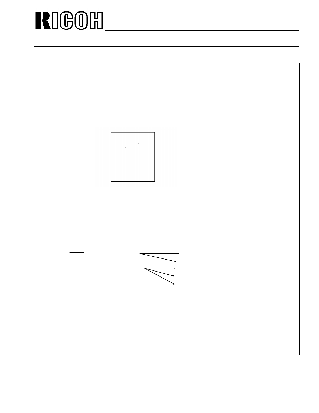
1. Problem
• Phenominon
1. The RX image may be reduced (3/4).
2. The end of the RX image (af te r B 5 len gt h) may be blurred.
3. The parts (left side) of the RX image may be rep eate d o n the righ t.
Technical Bulletin
No.CSO-001
FA X T.S. Section T.S. Department
Assistant General Manager
H. Motojima
Control No. f or Each Area
R.C. -- Asia 001
SAVIN -- LAM --
Europe -- A T&T --
HCS --
• Conditions
1. The specified cassette sele ction is on.
2. More than 2 pages are received.
3. The PFU is installed.
4. Memory RX (substitute reception, night timer, etc).
Under all of the above conditio ns, the prob lem may occu r.
2. Cause.
Software mistake.
3. Countermeasure
When installing the PFU (Paper Fee d Unit ) re pla ce the ROM on the machine.
(The ROMs will be provided from Ricoh Tokyo (FTSG). )
After replace the ROMs, che ck the ma chin e, in accord an ce with the att ach ed check she et ,
and return the sheets to Ricoh Tokyo (Attn. Mr Motojima) by air mail once a mont h.
4. Serial No.
December (1991) product ion only
A06112XXXXX
Page 2

Issued on
January 27th,1992
Technical Bulletin
No. CSO-002
Subject:
Model(s):
Classification
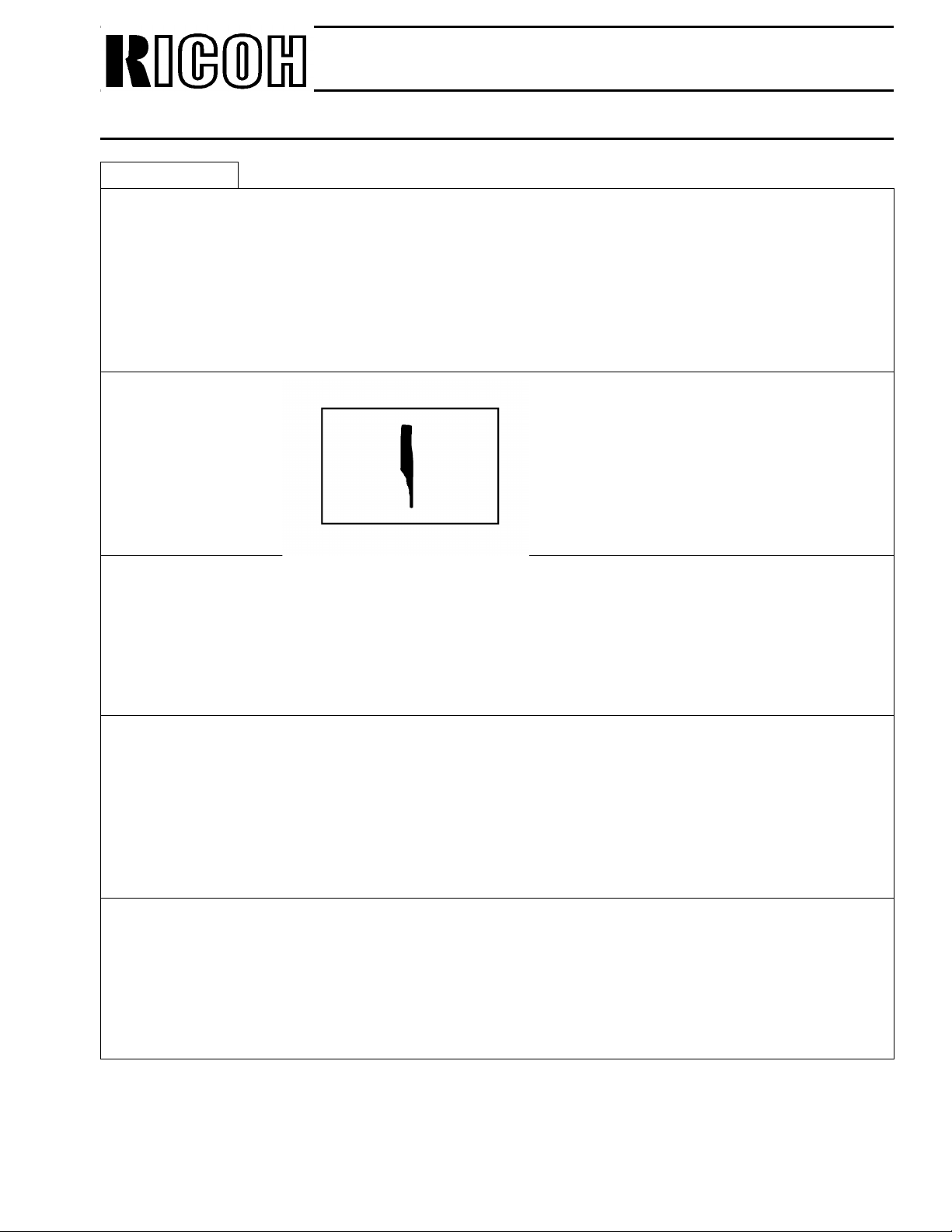
[Problem]
The document may not fee d at all if the customer place s 50 sheets in the ADF.
Document non-feed
FA X T.S. Section T.S. Department
Assistant General Manager
H. Motojima
Control No. f or Each Area
R.C. 0 01 Asia --
SAVIN 001 LAM 001
Europe 001 A T&T --
HCS 001
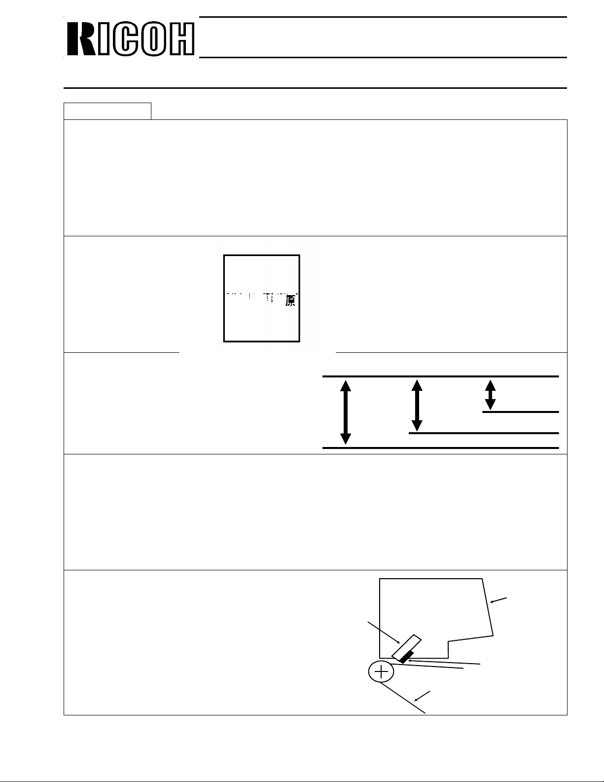
[Cause]
1. Static electricity. (In low humidity environment)
2. Some types of pap er, such as rough or thick types.
[Action]
Normally documents should be set with the edges even, because the CS O ha s a shut ter .
However, if the customer faces this problem, instruct the customer to do the following.
1. Shuff le the stack
2. Place the document in the fee de r a s follo ws
0~10mm
Inserting Direction
Page 3

Issued on
February 15, 1992
Technical Bulletin
No. CSO-003
Subject:
Model(s): AFO/AF2/CSO
Classificati on
Action Required
Troubleshooting
Retrof it Information
Revision of Service Manual
Inform a tion Only
Others
[Problem]
1. When a telephone call is incoming, the contact of the NCU OH relay may melt after quite a
few repetition of incoming calls. then no fax reception becomes available. (AFO/AF2/CSO)
AFO/AF2/CSO Software problem
FAX T.S. Section T.S. Depa rtmen t
Assistant General Manager
H. Motojima
Control No. for Each Area
R.C. -- Asia 002
SA V IN -- LAM 002
Europe 002 AT&T -HCS 002
2. The first printing page for a reception, a substitute file output, a report or a pattern output
may be blank. (AFO/AF2)
[Cause]
1. By a software fault, the DC loop over the OH relay is closed during an incoming call to result
in putting the ringing voltage (energy) through the DC loop.
The current faulty program allows the rin gin g off signal be enabled during a r inging sequence, so the OH relay is to be switched on.
Possible occurrence rate is ;
1/1800 ∼ 1/8300 at incoming calls.
(For more details, refer to page 3.)
2. By a software fault, the command for 24V power supplying to the thermal head may be
turned off instantly.
However, the printing sequence continues to result in a blank page outputted.
This is caused by the faulty priority assignment of the signals of 24V power on, of status
check and of RXSTART trigger.
It may occur at random as 36 µs/160 ms ≅ 1/4400.
Page 4
Issued on
February 15, 1992
Technical Bulletin
No. CSO-003
Subject:
[Countermeasure]
1. The program is corrected.
So, exchange the ROM on the MBU to the new one.
2. The program is corrected.
So, exchange the ROM on the MBU to the new one.
Part numbers
AFO/AF2/CSO Software problem
Version Old New ROM
Ricoh Europe/NRG H0847140C H0847140D
AFO
AF2
CSO
HCS H0847143C H0847143D
Language kit H0847150A H0847150B
Asia H0847141C H0847141D
Ricoh Europe/NRG H0867140C H0867140D
HCS H0867143C H0867143D
Language kit H0867150B H0867150C
Asia H0867141C H0867141D
Ricoh Europe/NRG H0817130G H0817130H
HCS H0817131G H0817131H
Language kit H0817159D H0817159E
Asia H0817132G H0817132H
[Affected machines]
The machines produced in Nov and Dec ’91 and in Jan ’92.
Note: Some of the above machines have been modified in Japa n before shipment.
Page 5

Subject:
Issued on
February 15, 1992
1. Faulty program
Ringing on/off flag
Ringing detection
Ringing detecting
prohibition flag
Technical Bulletin
No. CSO-003
AFO/AF2/CSO Software problem
Ringing
OH relay
2. Corrected prog ram
Ringing
Ringing on/off flag
Ringing detection
Ringing detecting
prohibition flag
OH relay
Page 6

Issued on
February 19th, 1992
Technical Bulletin
No. CSO-004
Subject:
Model(s): AFO/AF2
Classification
When installing the above mod els in Holla nd /I ta ly/B elg ium, change the NCU parpameter to
meet the PTT require men t as fo llows.
NCU parameter setting for Hol land
CSO
FA X T.S. Section T.S. Department
Assistant General Manager
H. Motojima
Control No. f or Each Area
R.C. -- Asia --
SAVIN -- LAM --
Europe 003 A T&T --
HCS 003
1. Change the country codes for NCU parameter and bitswitch.
2. Change the following parameters and RAM addresse s as follo ws.
[Holland]
NCU Parameter 002=020
NCU Parameter 003=080
NCU Parameter 004=020
NCU Parameter 005=080
NCU Parameter 006=002
NCU Parameter 010=058
NCU Parameter 011=058
NCU Parameter 012=042
NCU Parameter 013=042
Address 4144=5EH
Address 4152=5EH
Address 416A=5EH
Address 417F=02H
[Italy]
Address 4157=06H
Address 4158=00H
Address 4159=01H
Address 415A=00H
Address 4158=15H
Address 415C=15H
Address 4164=40H
[Belgium]
Address 413F=05H
Address 4140=20H
Address 4141=03H
Address 4142=00H
Address 414D=05H
Address 414E=20H
Address 414F=03H
Address 4150=00H
Address 4151=1EH
Address 4152=13H
Address 4153=1EH
Address 4154=04H
The above correction will be applied in to the soft ware from the 1st productions of March ’92.
Page 7

Issued on
March 3rd, 1992
Technical Bulletin
No. CSO-005
Subject:
Model(s): CSO
Classification
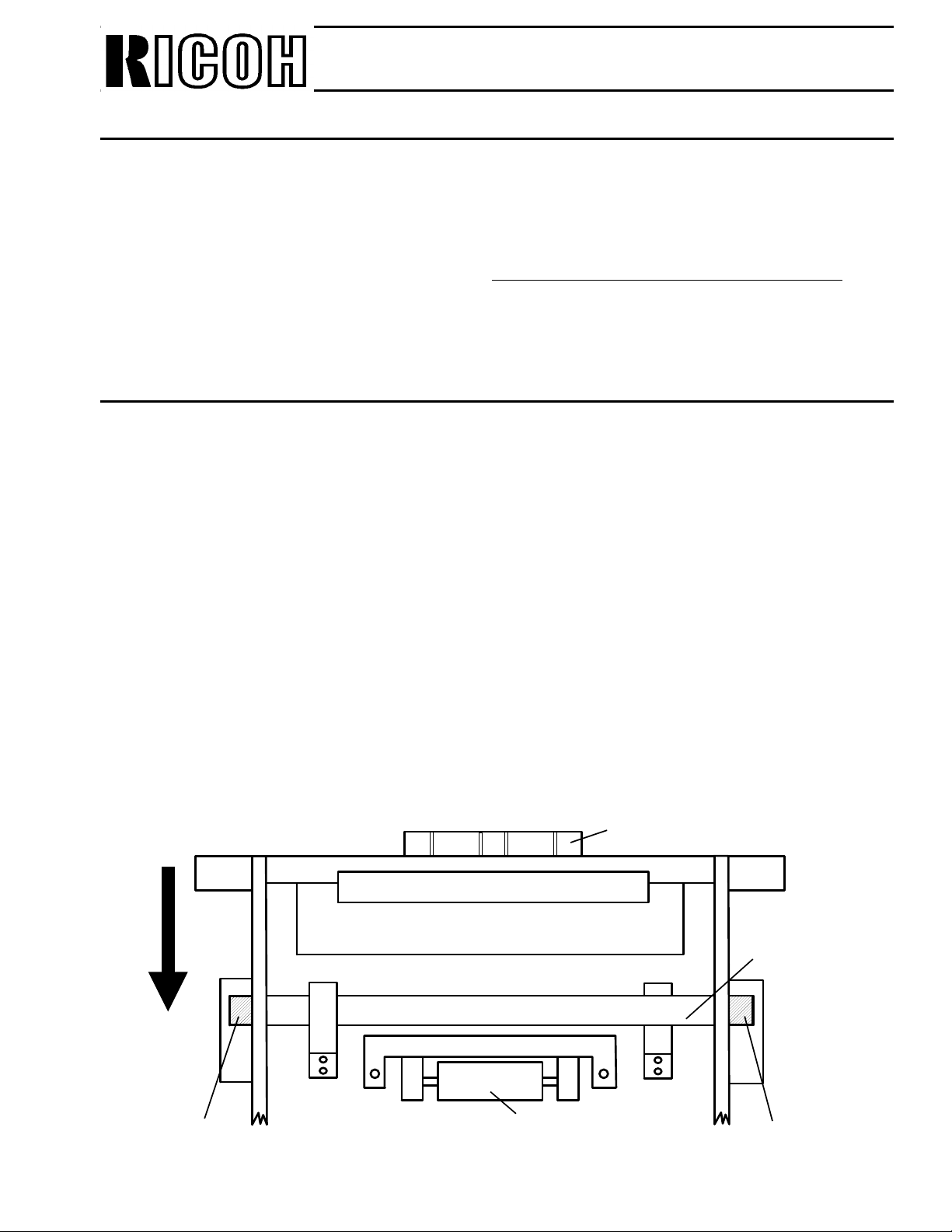
If the customer require A5 size pa pe r in t he pape r feed unit, adjust the spring pressure as
follows in order to prevent do uble feeding.
Optional paper feed unit adjustment
FA X T.S. Section T.S. Department
Assistant General Manager
H. Motojima
Control No. f or Each Area
R.C. -- Asia --
SAVIN -- LAM --
Europe 004 A T&T --
HCS 004
1. Remove the right cover.
2. Adjust the spring pressu re by th e ad justment bracket as shown belo w. (by loosening 2
screws)
3. Put the cover back.
Page 8

Duct
Remaining Toner
Issued on
March 5th, 1992.
Technical Bulletin
No. CSO-006
Subject:
Model(s): CSO
Classificati on
Action Required
Troubleshooting
Retrof it Information
Revision of Service Manual
Inform a tion Only
Others
Once the machine is installed (with the Toner Cassette installed in the machine), the toner will
be transferred to the developing unit. As a result, when the Toner Cassette is removed from the
machin e, some residual toner may s pill out from the de veloping unit when the ma chine is
moved.
Duct cover for the development unit
FAX T.S. Section T.S. Depa rtmen t
Assistant General Manager
H. Motojima
Control No. for Each Area
R.C. 002 Asia 003
SA V IN 002 LAM 003
Europe 005 AT&T ---
HCS 005
If it is necessary to transport the machine after installation, please do the following:
1. Switch off the power, and r emove the toner cassette.
2. Remove the remaining toner at the duct entrance by
tapping the duct.
3. Close the front cover without putting back the toner
cassette.
4. Using the test mode, rotate the toner supplier as follows.
(1) Enter test mode: Function 5 1 9 9 1
(2) 9 7 Yes
(3) 8
(4) After the noise from the toner supply mechanism stops, press Stop
5. Push the duct cover (H0812487) into the development un it with a screwdriver.
Longer
Duct
H0812487
H0812487
6. Switch off the power.
7. Move the machine.
Shorter
15mm
Page 9

Issued on
March 16 , 1992
Technical Bulletin
No. CSO-007
Subject:
Model(s): CSO
Classification
When the power is kept on, the PCB-PFU will be bro ken aft er connecting/disconnecting the
connectors during instalation/checking th e lower paper feed unit.
Lower paper feed unit
FA X T.S. Sectio n, T.S. Department
Assistant General Manager
H. Motojima
Control No. f or Each Area
R.C. 003 Europe 006
SAVIN 003 HCS 006
NRG-
USA
-- NRG --
Asia/LAM 004
Therefore, before connecting/disconnecting the paper fee d un it, plea se make sure that the
power is switched off.
Page 10

Issued on
March 18th, 1992
Technical Bulletin
No. CSO-008
Subject:
Model(s): AFO/AF2/CSO
Classification
-Problem-
If the T1 timer is set with a value of over 100 for a speed dial code by d ed icated Tx parameter
programming, the other parame te r for th e spe ed dial cod es will not be programmed.
Dedicated Tx parameter programming problem
FA X T.S. Sectio n, T.S. Department
Assistant General Manager
H. Motojima
Control No. f or Each Area
R.C. 004 Europe 007
SAVIN 004 HCS 007
NRG-
USA
001 NRG 001
Asia/LAM 005
-Cause-
Software bug.
-Countermeasure-
Temporary- Set the T1 timer with a value less than 100 for spe ed dia l codes.
Permanent - We will correct the software from the May mass pro duction.
Page 11

Page
418E=12H
1
Technical Bulletin
KMxml
Subject:
Model(s): AFO/AF2
Classification
Action Required
u-
Troubleshooting
❑
Retrofit Information
❑
Revision of Service Manual
Information Only
El
❑
Others
When installing the above models in Sweden, change the
PTT/sales
the
NCU
Cso
requirements as follows.
No.cso-009
parameter setting
for
FAX
Assistant General Manager
H.
Control No. for Each Area
Sweden
T.S.
Section
McWinTJii-nTJ>z~
R.C. --
SAVIN
NRG-USA
Issued on
March 19th, 1992
T.S.
Department
j
,
)
(Y
Europe
--
--
NCU
parameter in accordance with
HCS
NRG
Asia/LAM
008
008
002
--
1. Change the country codes for NCU parameter and bitswitches.
2. Change the and RAM addresses and bit switch as follows.
(PTT requirement)
Address 4172 = 60H
Address 4173 = 20H
Address 4174 = 60H
Address 4175 = 03H
Address 4176 = 19H
The above correction will be applied into the software from the
(Sales requirement)
Address 406C bit 5 =
Address 4063 bit 7 = O
Bit sw SW06 = F0H
1st
bit6=l
0,
productions of May ’92.
4143=28H
4145=28H
4151=28H
4153=28H
4172=28H
4174=28H
Page 12

Issued on
April 15th, 1992
Technical Bulletin
No.CSO-010
Subject:
Model(s): CSO (Europe and Asia)
Classificati on
Action Required
Troubleshooting
Retrof it Information
Revision of Service Manual
Inform a tion Only
Others
We issue the correction for the service manual for CSO.
Please refer to the attached.
Service Manual Correction
FAX T.S. Section, T.S. D epartment
Assistant General Manager
H. Motojima
Page 13

Issued on
April 24th, 1992
Technical Bulletin
No.CSO-011
Subject:
Model(s): AFO AF2/CSO
Classificati on
Action Required
Troubleshooting
Retrof it Information
Revision of Service Manual
Inform a tion Only
Others
When installing the above models in Switzerland, you have to apply the modification as th e
following steps.
NCU Modifi cation for Switzerland
(Europe only)
FAX T.S. Section, T.S. D epartment
Assistant General Manager
H. Motojima
1. Prepare the following parts at your side.
(1) Resister - 10Ω: 1/10W
(2) Capacitor - 0.047µF /250V
(3) C oil - TDK ELF 1010 SKI-332k (3.3m H)
2. Remove the NCU from the machine, then apply the modification.
(1) Replace the R17 with the above resister (10Ω)
(2) Add the capacitor and coil, and cut the pattern as shown on the next page.
3. Put the NCU back, and reassemble the machine.
4. Check the machine for the following items.
• Dialling (PD/DTMF)
• Transmission
• Reception
Page 14

Issued on
April 30th, 1992
Technical Bulletin
No.CSO-012
Subject:
Model(s): CSO
Classification
If you have any copy quality pro blems, make sure of the causes and solve the problem,
in accordance with the following pages.
T roubl es hooti ng
FA X T.S. Sectio n, T.S. Department
Assistant General Manager
H. Motojima
Page 15
Subject:
Issued on
April 30th, 1992
Troubleshooting
No. 1
Problem
OPC fragmentation
Image sample
Technical Bulletin
No.CSO-012
Characteristics of t he problem
The above image will appear every 188mm (one cycle of the OPC).
Cause
As a result of shock or scratching th e OPC, part of the OPC will come of f .
Action
Replace the OPC.
Page 16

Subject:
Issued on
April 30th, 1992
No. 2
Problem
Toner spillage.
Image sample
Technical Bulletin
No.CSO-012
Troubleshooting
Characteristics of t he problem
A lot of toner is attached on the copy.
Cause
There is a defective cleanin g rolle r b lad e in the used toner tank, or th e use d toner tank is full.
Action
Replace the CTM.
Page 17

Subject:
Issued on
April 30th, 1992
No. 3
Problem
Image flow.
Image sample
Technical Bulletin
No.CSO-012
Troubleshooting
Characteristics of t he problem
•The image has flowed in the sub scan direction.
•The boundary of the flow is not clear.
Cause
The OPC guide is attached to the OPC belt at point A .
Action
Replace the OPC.
Point A
Page 18

Subject:
Issued on
April 30th, 1992
Troubleshooting
No. 4
Problem
Incomplete transf er
Image sample
Technical Bulletin
No.CSO-012
Characteristics of t he problem
Part of image data is omitted in the same pla ce acro ss t he page.
Cause
Toner stuck to the transfer corona wire.
Action
Clean the transfer corona wire.
Page 19
Subject:
Issued on
April 30th, 1992
No. 5
Problem
Dirty Backgrand.
Image sample
Technical Bulletin
No.CSO-012
Troubleshooting
Characteristics of t he problem
Many clean black dots.
Cause
Shortage of change, cau sed by OPC stress.
Action
Rreplace the OPC.
Page 20
Subject:
Issued on
April 30th, 1992
Troubleshooting
No. 6
Problem
Tortoiseshell putterning
Image sample
Technical Bulletin
No.CSO-012
Characteristics of t he problem
This problem occurs in areas of inte rmed iat e de nsit y.
Cause
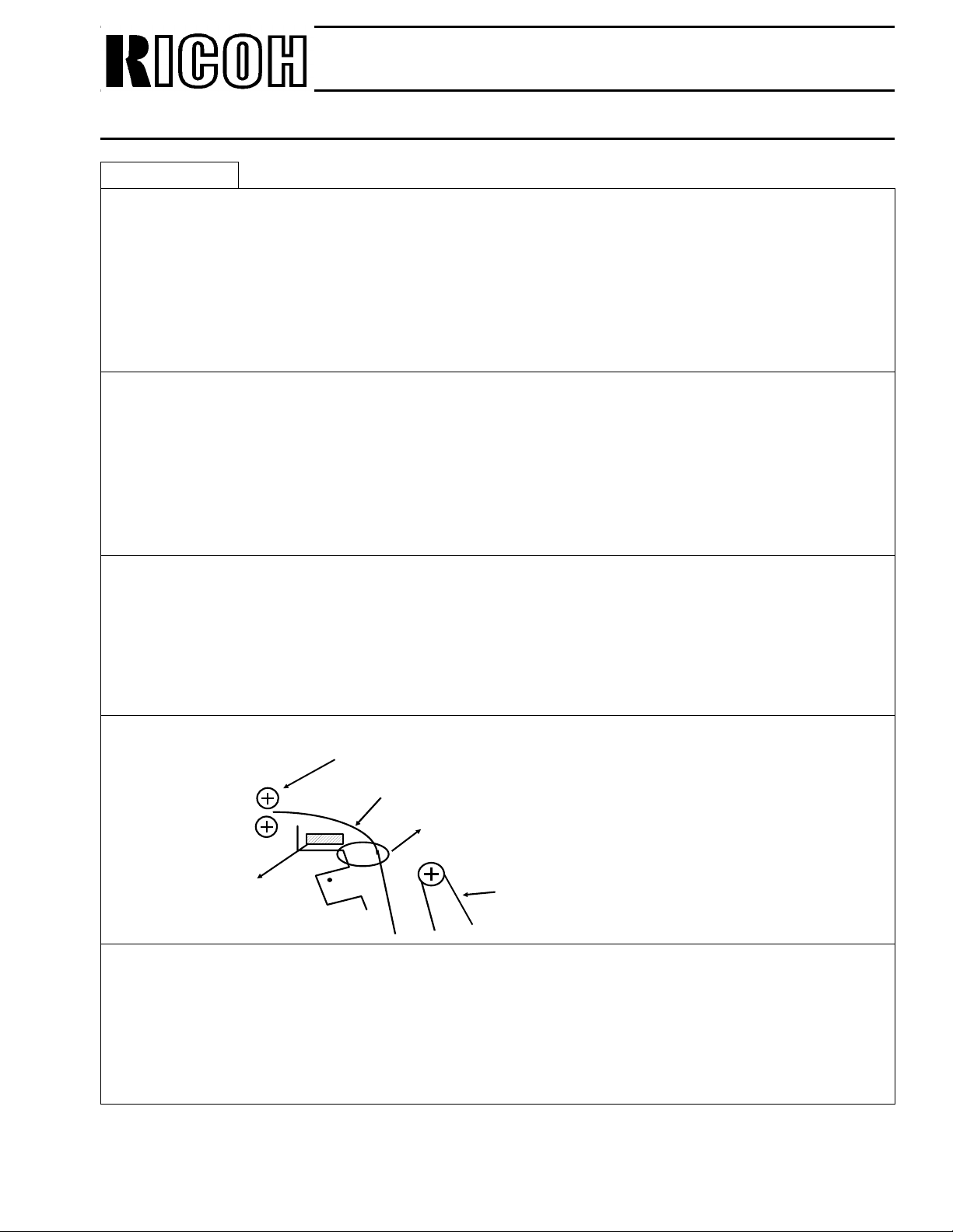
Pressure Roller
Copy Paper
Point A
Antistatic
sheet or brush
OPC
Action
Attach an antistatic she et or brush.
Toner has burst out due to a leak at
point A.
Page 21

Subject:
Issued on
April 30th, 1992
No. 7
Problem
Black dots.
Image sample
Technical Bulletin
No.CSO-012
Troubleshooting
Characteristics of t he problem
Dots appear at an interval of 14mm or 188mm.
Cause
(1) 14 mm interval → Defective develo pment roller
(2) 88mm interval → Defective OPC
Action
(1) Replace the developmen t unit.
(1) Replace the OPC.
Page 22
Subject:
Issued on
April 30th, 1992
No. 8
Problem
Dirty background.
Image sample
Technical Bulletin
No.CSO-012
Troubleshooting
Characteristics of t he problem
Blurred horizontal stripes on the backg round.
Cause
• OPC Over charged OP C Icorrect setting of OPC voltag e. (1)
Incorrect setting of OPC. (2)
Under charged OPC Incorrect setting of OPC voltage. (3)
Incorrect setting of OP C. (4)
Defective OPC (5)
•Defective development unit (6)
Action
(1), (3) Replace the power pack.
(2), (4) Check the OPC insta llat ion or replace the OPC
(5) Replace the OPC.
(6) Replace the developmen t unit.
Page 23

Subject:
Issued on
April 30th, 1992
No. 9
Problem
White dots.
Image sample
Technical Bulletin
No.CSO-012
Troubleshooting
Characteristics of t he problem
The dots appear at intervals of 14mm or 188 mm.
Cause
14mm → Defective development unit.
188mm → Defective OPC
Action
(1) Replace the developmen t unit.
(2) Replace the OPC.
Page 24
Subject:
Issued on
April 30th, 1992
Troubleshooting
No. 10
Problem
Black Band (sub scan)
Image sample
Technical Bulletin
No.CSO-012
Characteristics of t he problem
Wide Black band
It may not be straight; it may be oblique, curved or broken.
Cause
Something such as toner ha s att ached itself to the charge co ron a wire.
Action
Clean the charge corona wire.
Page 25

Subject:
Issued on
April 30th, 1992
Troubleshooting
No. 11
Problem
Black line (sub scan)
Image sample
Technical Bulletin
No.CSO-012
Characteristics of t he problem
Pale, thin, straight line s.
Cause
Incorrect cleaning, caused by cracks on the edge of the cleaning blade(CTM).
Action
Check the CTM installation, or replace the CTM.
Page 26
OPC
Blade
CTM
Toner
188mm
160mm
48mm
Printing start position
Subject:
Issued on
April 30th, 1992
Troubleshooting
No. 12
Problem
Black lines (Main scan)
Image sample
Technical Bulletin
No.CSO-012
Characteristics of t he problem
The lines appear as follows
Cause
•Dirt on the reverse side of the cleaning blade (CTM) or incorrect size of CTM or blade
Action
•Clean the reverse side of the cleaning blade .
•Replace the CTM
Page 27

Issued on
May 12th, 1992
Technical Bulletin
No.CSO - 013
Subject:
Model(s): AFO / AF2 / CSO
Classification
[Problem]
The above models may not transmit to the following models.
(Error code 0 - 21 / 0 - 23)
The document may stop during scanning, then th e mach ine will reset after 1 ∼ 2 min, and the
power failure report will be printed.
During transmission, th e stop key does not function.
Condition : I / O rate 40ms (standard), 20ms (Detail)
Models : UF32H • UF23 (Matsushita)
Communication Problem
FA X T.S. Sectio n, T.S. Department
Assistant General Manager
H. Motojima
[Cause]
A sof tware error
On the Tx side, the fill bit will be added if the 1 line data is less than the min Tx time for 1 line,
however on the above AFO / AF2 / CSO, the counting may be inco rrect .
[Countermeature]
Temporary : Using the dedicated Tx paramete r, select 4800bps of the initial modem rate.
Permanent : The 1st production of March ’92 will con ta in t he correct software.
Page 28

Issued on
May 12th, 1992
Technical Bulletin
No. CSO - 014
Subject:
Model(s): AFO / AF2 / CSO
Classification
[Problem]
The avove models can not re ceive using ECM from the machines which use 64 fra mes, such as
Canofax 470.
Communication Problem
FA X T.S. Sectio n, T.S. Department
Assistant General Manager
H. Motojima
[Cause]
A sof tware error
The frame size (256 / 64 frame) can no t be chan ge d in the software.
[Countermeature]
Temporary
If you face this problem, switch off the ECM function.
(Bit sw 07, bit 5 0 → 1)
In the field, most of facsimile machines use 256 frame, so, this proble m may occur rarely.
Permanent
The 1st production of May ’92 will con ta in the corre ct software.
Page 29
Handle
Subject:
Issued on
May 25th, 1992
Model(s): CSO
Classification
[Problem]
Technical Bulletin
No.CSO-015
Difficult to remove the upper cassette
FA X T.S. Sectio n, T.S. Department
Assistant General Manager
H. Motojima
It is difficult to remove the upper cassette fro m the machine when adding the pa pe r.
[Cause]
Friction between the Cassette Retaining Shaft and Cassette Guide Rail.
[Countermeasure]
Lubricate both sides of the Cassette Retaing Shaft .
(Refer to the diagram b elo w).
Use P/N 52 039501 Grease 501
This modification was completed from March, 1992.
Direction of Insertion
+
-
+
Cassette
Retaining Shaf t
Lubrecate Here
Roller
Lubricate Here
[ Viewed from the bottom of the cassette]
Page 30

Issued on
May 15th, 1992
Technical Bulletin
No. CSO - 016
Subject:
Model(s): CSO
Classification
[Problem]
The CSO may not receive from th e following models, with 9600 bps / 72 00 bps.
(1) SANFAX 1 / 515
(2) PC FAX (Mac, PC98, IBM 400)
(3) Pana FAX UF 1000
Communication Trouble
FA X T.S. Sectio n, T.S. Department
Assistant General Manager
H. Motojima
[Cause]
The signalling rates in the ab ove ma chin es (1) (2) an d (3) are out of CCITT recommendation,
therefore, the CSO can not receive V29 signal corre ctly.
Capture Rang e of CSO : 9600 bps ± 0.01% (100ppm)
CCITT recommendatio n : 96 00 bps ± 0.01%
[Countermeasure]
Temporary - At present, these is no way of solving this problem from the Ricoh side.
Please ask the possibility of solving this pro ble m (su ch as exch an gin g
modem) from the Tx side.
Permanent - We are correcting the capture range of the CSO as follows.
9600 bps +230 ppm - 300 ppm (temporary range)
From the result of the test, fin ally we will fix it and apply to th e machine.
Page 31

Issued on
May 22nd, 1992
Technical Bulletin
No. CSO - 017
Subject:
Model(s): AFO / AF2 / CSO (Europe)
Classification
[Problem]
When installing the above mode ls in De nma rk, S witzerland and Austria, change the f ollo wing
addresses in accordance with the PTT requierments it the mach ine Serial Number is prior to the
following excution date.
1. Change the country codes for NCU parameter and bit switch.
2. Change the RAM addresses as follows.
NCU parameter setting for Denma rk, Switz erland and Aus tr ia
FA X T.S. Sectio n, T.S. Department
Assistant General Manager
H. Motojima
[Denmark]
4149 =04H, 414A =60H, 414B =03H, 414C =90H, 415B =OCH, 415C =OCH,
415D =08H, 415E =17H, 414D =05H, 41 4E =1 2H, 414F =0 3H, 4150 =40 H,
4151 = 41H, 4152 = 3FH, 4153 = 41H, 4154 = 04H, 4155 = 19H, 4157 = 04H,
4158 =60H, 4159 =03H, 415A =90H, 4164 =42H
These corrections have bee n applie d fro m t he 1st pro du ctio n of March ’92 .
[Switzerland]
4181 =05H, 4143 =28H, 4145 =28H, 41 64 =51H, 415B =18, 415C =1EH,
415D =OFH, 415E =16H, 415F =OBH, 4160 =OBH, 4161 =08H, 4162 =1EH,
4064(bit 5) =1
These corrections have bee n applie d fro m t he 1st pro du ctio n of May ’92.
Page 32

Subject:
Issued on
May 22nd, 1992
NCU parameter setting for Denma rk, Switz erland and Aus tr ia
[Austria]
AFO/AF2/CSO
Addr.
4058: → 0AH
4059: → 01H
4143: → 28H
4178: → 64H
417D: → 0EH
417E: → 0AH
417F: → 01H
4182: → 14H
4183: → 50H
4187: → 09H
4190: → 50H
4191: → 50H
4192: → 07H
Technical Bulletin
No. CSO - 017
CSO
Bit SW
Bit SW 01: → 03H
Bit SW 02: → 40H
Bit SW 03: → 4AH
Bit SW 05: → 27H
Bit SW 07: → 46H
Bit SW 0B: → 06H
Depending on the sales req uire ment, change
the followings.
User SW
User Bit SW 01: → 41H
User Bit SW 02: → 0BH
User Bit SW 03: → F5H
User Bit SW 06: → 0BH
AFO/AF2
Bit SW
Bit SW 01: → 07H
Bit SW 02: → 58H
Bit SW 03: → 4AH
Bit SW 05: → 27H
Bit SW 07: → 06H
Bit SW 0B: → 06H
Depending on the sales req uire ment, change
the followings.
User SW
User SW 03: → F5H
After correcting the sof tware, we will apply to the machine(except user SW).
Page 33

Issued on
June 1st, 1992
Technical Bulletin
No. CSO - 018
Subject:
Model(s): CSO
Classification
[Problem]
The toner guide gear may break because of stress caused by too mu ch to ne r in the
development unit, into which toner is being supplied cont inu ou sly.
As a result white lines will appear on the cop y.
Toner Guide Gear (H0812437) breakage
FA X T.S. Sectio n, T.S. Department
Assistant General Manager
H. Motojima
[Cause]
• The toner end detection lever be nds easily when it suffers from some ext ern al sho ck, be -
cause the material is not th ick eno ug h.
• The position of the toner end sensor or the toner detection lever mylar is in corre ct.
• If the lever is bent, or the positio n of the sensor or the mylar is incorrect, to ne r is supplie d
continuously and fills up over the maximum level, beca use the toner en d dete cto r doe s not
work properly.
• Ultimately, the toner trough is not retu rne d to its initial position, and the toner guide gear
breaks, because it expe rien ces too much stress during toner sup ply.
[Action]
• We have modified the fo llowin g part s f rom April production.
Regarding the serial no., refe r t o the atta ched list.
Lever : T oner End Detector → H0812422D
Spring : Lever → H0812462D
Shutter : Toner End Detector → Deleted
• If you face the above problem in the field, please throw some toner away, and replace the
toner guide gear (H0812473) with the abo ve parts (H0812422 and H0812462).
Also, please make sure tha t th e other parts of the develo pme nt unit such as the agitator or
gears, are not damaged.
Page 34

Issued on
June 1st, 1992
Technical Bulletin
No. CSO - 018
Subject:
[Probability]
Around 0.2% .... . acco rding to the Japanese domest ic ma rket dat a
Note: Probability does not mean the F/R per month.
[Serial Nos]
Toner Guide Gear (H0812437) breakage
<H081-20 > R6720401099~
<H081-23 > R7320401001~
<H081-60> 6012241354~
<Others> From 1st production of May, ’92
Page 35

Issued on
June 5th, 1992
Technical Bulletin
No.CSO-019
Subject:
Model(s): CSO
Classification
[Problem]
Toner leakage inside unit or on the copy durin g no rmal op era tion.
Toner Leakage
FA X T.S. Sectio n, T.S. Department
Assistant General Manager
H. Motojima
[Cause]
The adhesion of th e bru sh on to the toner retainer blade in the cleaning part of the toner
cassette became poor, opening a small gap(s).
Then, the cleane d off toner leaked out through the above poor adhesion gap.
Cause of the poor adhesion
a. Application of stress to mount the brush with double sided adhesive tape was not even.
b. The area where the adhesive tap e was applie d was n ot well cleaned.
[Action]
We conclude that this problem would occur rarely, this means that only few toner cassettes may
have the possibility of this proble m a t very low rat e.
So, if you face this prob lem in the field, you can solve by rep lacin g the toner cassette with other
cassette.
Also, we have improved th e production procedure of on e to ne r cassette in our factory, in order
to increase the reliability.
Page 36

White tape
Subject:
Issued on
June 8th, 1992
Model(s): CSO
Classification
[Problem]
Technical Bulletin
No.CSO-020
Caution when installing the OPC(Mas ter Unit)
FA X T.S. Sectio n, T.S. Department
Assistant General Manager
H. Motojima
Black dots or lines on the printed image at 88mm intervals.
[Cause]
Defective OPC.
(The OPC might fall down during installation, rese tt ing or replacement of th e OP C.)
[Reason]
The OPC may drop if the tech nician removes the two white tap es on the OPC ho lder before
installation.
[Action]
Remove the two white tapes on the OPC holder afte r ins t al li ng the OPC in the ma chi ne.
Page 37

Issued on
June 23rd, 1992
Technical Bulletin
No.CSO-021
Subject:
Model(s): CSO
Classification
Action Required
Trou bleshooting
Retrofit Information
Revision of Service Manual
Information Only
Others
[Problem]
When printing, you may h ear noise from around the bushing fo r the pap er feed roller.
Noise when printing
FA X T.S. Sectio n, T.S. Department
Assistant General Manager
H. Motojima
Some customers may complain about this no ise if th e mach ine is used in a quiet place.
However, this noise level is within our specificat ion s.
[Countermeasure]
We have already add ed the sp ring plat e (H0813410) to the machine in order to decrease the
noise.
So, if you receive a complain t ab ou t a mach ine which has not received the mod ification,
concerning the ab ove noise, please add the sp ring plate, as shown on the ne xt pa ge .
Regarding the serial n os, plea se refer to the next page.
Page 38

3
Issued on
June 23rd, 1992
Technical Bulletin
No.CSO-021
Subject:
1. Remove the left cover.
2. Remove gears and belt ( 1, 2 , 3, 4 ).
1
2
Noise when printing
4
3. Attach the spring pla te (H0813 410).
4. Reassemble the machine.
H081 - 20 R6720400001
H081 - 21 61022700 63
H081 - 22 6112240110
H081 - 23 R7320400001
H081 - 24 R7420600001
H081 - 26 S2320400 001
H081 - 27 S1920400 001
H081 - 28 L4020401 601
H081 - 29 L4120401 401
H081 - 51 A0620400 001
H081 - 59 60222401 36
H081 - 30 45805200 01
H081 - 40 U1720500001
H081 - 60 60122515 04
H0813410
Page 39

Technical Bulletin No. CSO-022
Page 1/3
SUBJECT: Modem Capture Range Problem
PREPARED BY: N.Mihar a
CHECKED BY:
CLASSIFICATION:
Action Required Revision of service manual
Troubleshooting Information only
Retrofit Information Other
FROM: FAX T.S. Section
MODEL: CSO, AFO, AF2
DATE: August 21st, 1992
Reissued: Sept 29, 1992
[Problem]
The CSO/AFO/AF2 may not receive at 9600bp s/7200bps from the certain machines, with the
following phenomenon.
• Error code: 0-21, 23
• Only the 1st few inches (cm) of the imag e data would be received and then the line would
be disconnected, or the error would occur as the usual Line fail.
[Cause]
On the CCITT recommendation, the signalling r a te o f the TX terminal is defined to be 9600bps
± 0.01% (100ppm), and all makers design the facsimile models in accordance with the CCITT
recommendation. However, on the some of the models (Tx side) , the signallin g rate may be out of
CCITT recommendation, due to the possible production variation of modem, or other factors.
The capture range (Rx capability) of t he CSO/AFO/AF2 is designed as 9600bps ± 100ppm(there is
no margin). Therefor e, if the signalling rate of Tx terminal is out of CCITT recom mendation, the
CSO/AFO/AF2 can not receive the V29 signal correctly. It means that, if a modem is produced
precisely, there will not be the prob lem.
Tx side: Signalling rate of CCITT recommendation - 9600bps ± 100ppm
Rx side: Capture range of CCITT recommendation - none
[Countermeasure]
Permanent: We have re-designed the modem, to have cert ain margin fo r reception and the new
modem will be ap plied from Oct. produ ctions of ’92 except the fo llowing.
CSO (Productions at RIF factory) → From November, 1992
AFO/AF2 (Productions at RIF factory) → From December, 1992.
The P/Ns of the FCUs will be changed as follows.
Old New
H08160xx → H08161xx ( The last two digits will not be changed)
H08460xx → H084603x
H08660xx → H086603x
(The last digit will not be changed)
Page 40

Technical Bulletin No. CSO-022
Page 2/3
SUBJECT: Modem Capture Range Problem
DATE: August 21st, 1992
Reissued: Sept 29, 1992
[Action in the field]
(1) Make sure the exact causes of the communication problem. By referring to the attached
troubleshooting flow, because there are other communication problems which are caused by
other reasons. If the problem is caused by this modem capture range problem, go to the next
steps.
(2) Drop the starting modem rate of the terminal for Rx or Tx.
(3) Ask the Tx terminal to replace the modem.
(4) If (3) is not possible, replace the FCU with the new FCU which contains the new modem.
[Sample]
Until now, we have been reported on this pro blem with the following models at few rate, and as
the result of our investigation, the signalling rates of the machines are as follows.
Models Signalling rate
SANFAX 2100 Unknown (The modem has been
rep laced on the tx side)
SANFAX 1 -163ppm
SANFAX 515 Unknown
Panafax UF1000 -120ppm
PC98 FAX (Star FA X) + 120ppm
PC FAX Mac -180ppm
IBM PC FAX Unknown
Please note that the above table is just the samples of the problem, and the problem should not
always occur with the above models in your field.
The estimated occurrence rate is as low as 0.05%/mo.
However, we like to keep watching the field performance.
We like you to log this case monthly.
Page 41

Technical Bulletin No. CSO-022
Page 3/3
SUBJECT: Modem Capture Range Problem
Phenominom: -Frequent Error Reports (User)
-Frequent Error Co des (Service) 0-20/0-21/ 0-23
START
Error Condition
R x Error(s) occur only in a few
cases and always from the same
Tra ns mitting Terminal
DATE: August 21st, 1992
Reissued: Sept 29, 1992
Error Condition
R x Error(s) occur often from
different Transmitting Terminals.
Change Rx Speed to 7200 bps
OK: E rror(s) caused by bad line
condition.
NG: P roceed with the next step.
Change Rx Speed to 4800 bps
OK: We suspect the AFSP chip
(modem) on the FCU.
Please find out the machine
type at the Tx side.
NG: Proceed with the next step.
Change Rx Speed to previous Speed.
Change Training Error Tolerance
OK: Error(s) cause d by bad
line condition.
NG: Proceed with the next step.
Change Line Error Threshold
OK: Error(s) cause d by bad
line condition.
NG: Proceed with the next step
Change Rx Speed to 4800 bps
OK: Error(s) cause d by bad
line condition.
NG: We suspect the AFE chip on
the FCU. Replace the FCU
with a another FCU
Page 42

Technical Bulletin No. CSO-023
SUBJECT: CSO Swiss Version
PREPARED BY: H.Yokoya ma
CHECKED BY:
CLASSIFICATION:
Action Required Revision of service manual
Troubleshooting Information only
Retrofit Information Other
We inform you that we will make a version of CSO for Switzerland, in which it is not necessary
to change any jumpers at installation.
The details are as follows.
FROM: FAX T.S. Section
MODEL:
DATE:
December 11th, 1992
CSO
-Mass Production-
September, 1992
-Difference-
MBU (P/N: H0816025)
NCU (P/N: H0846020)
Other parts are the s ame as CSO European version.
-Production Code-
H081-46
Page 43

Technical Bulletin No. CSO-024
SUBJECT: Softwa re Problem
PREPARED BY: A. Ishiyama
CHECKED BY:
CLASSIFICATION:
Action Required Revision of service manual
Troubleshooting Information only
Retrofit Information Other
FROM: FAX T.S. Section
MODEL:
CSO for Ricoh and NRG
DATE:
Decem ber, 3rd, 1992
[ Problem]
When receiving, the machine alw ays sends out a CFR (Confirmation to Receive) as a response
to modem training.
As a result, communication fails (reception error) if the telephone line is poor, because the
transmission modem rate never falls back.
(This will not happen with ECM communication)
[Cause]
When some of the software modifications were executed, a bug was introduced.
[Countermeasure]
The program has been corrected.
So, change the ROM or the MBU.
ROM Part Numbers
Version Old P/No. Ne w P/N o.
Ricoh FAX3000L H081 7140J H081 7140K
Eurpe H081 7130M H081 7130N
Swiss H081 7131M H081 7131N
Asia H081 7132M H081 7132N
[Affected Machines]
The machines produced in November 1992.
Notes: 1. Most of the abo ve machines have been modified in Japan before ship ment .
2. Only for Ricoh brand CSO 115 Volt version, Please note that the serial numbers
earlier than xx21100602 are out of the app licab le machines, because those are
equipped with the o lder ROM(H 081 7140H) which does not contain t he problem.
Page 44

Technical Bulletin No. CSO-026
SUBJECT: Scratch on the OPU
PREPARED BY: N. Mihara
CHECKED BY:
CLASSIFICATION:
Action Required Revision of service manual
Troubleshooting Information only
Retrofit Information Other
FROM: FAX T.S. Section
Problem
The OPU may be damaged when using the machine, as shown
below. However, there is no problem on the printed image.
Cause
1. Both sides of the development roller may touch the metal
blade on the development roller. By this, the shaved
corpuscles may get in the space between the OPU belt and
the development roller, the both sides of the OPU belt may be
damaged.
DATE:
April 15th, 1993
MODEL: CSO
Scratch
OPU guide
2. The position of the OPU guide may be changed for some
reason, then the OPU belt may touch the plastic pins on
the develpment unit.
Action
1. If the above problem occurs, do not replace the OPU, because, there will be no problem on
the printed image, in the lifetime of the OPU.
2. Do not adjust and change the position of the OPU guide.
Note
Do not touch the sorface of the OPU belt and not clean with alcohol.
Page 45

Technical Bulletin No. CSO-027
SUBJECT: Tx cable Equ alizer
PREPARED BY: N. Mihara
CHECKED BY:
CLASSIFICATION:
Action Required Revision of service manual
Troubleshooting Information only
Retrofit Information Other
We have added the tx equalizer feature an d char ged th e setting for the r x equ alizer by changing
the s oftware and the hardware as show n below. (MB CSO-027)
With these charge, more proper setting will be available for the communication quality.
FROM: FAX T.S. Section
MODEL: CSO
DATE:
April 14th, 1993
1. New setting
Bit SW 0A (Rx cable equalizer)
Bit SW 08 (Tx cable equalizer)
bit 7 bit 6
0 0 (OFF) 00
0 1 (Middle) 10
10(High) 20
1 1 (Not used) Do not change
Regarding the Tx equalizer, it will be available only with the following combination.
Equalizer information on the TCR
(Journal)
(When Bit SW 00, bit 1 = 1)
2. Combination of the parts
FCU (MB CSO-035) MBU (MB CSO-027) ROM (MB CSO-027)
USA H0816153: USα
H0816152: USβ
H0816155: Telα
H0816154: Telβ
EUR H0816151 H0816025 R
Asia H0816156 H0816027 R H0817132 N
Regarding the affected date, please refer to the above MBS.
H0816026 N H0817140K
H0816039 E H0817139D
H0817131N HCS
H0816024 R
H0816029 F
--
H0817130N RICOH/ NRG
H0817133E France
H0817159K Language kit
Page 46

[2]
[1]
3rd mirror
Technical Bulletin No. CSO-028
SUBJECT: Dirty Mirrors
PREPARED BY: N. Mihara
CHECKED BY:
CLASSIFICATION:
FROM: FAX T.S. Section
MODEL: CSO
DATE:
Action Required Revision of service manual
Troubleshooting Information only
Retrofit Information Other
— Problem —
In the field, the scanner mirrors may become dusty (poor scanning quality).
In this case, we recommend that you do procedures 1 and 2.
— Procedure —
Proce dure 1.
Clean the mirrors with the mirror cleaning kit.
It is easy to clean the mirrors (there is no need to remove the ADF base).
June 30, 1993.
P/N: H0819300 (for CSO) Mirror C leaning Kit
• Mirror Cleaning Tool × 1pc
• Cleaning Felt × 30pcs
• Vinyl Bag × 1pc
[Preparation]
Attach the cleaning felts [1] to the mirror cleaning tool [2]. (Fig. 1)
(With one set of felts, you can clean the mirror up to 10 times)
[Cleaning Method]
(1) Remove the exposure glass.
(2) Insert the cleaning tool into the scanner. (Fig. 2)
(3) Clean the mirrors by sliding the tool.
(3~ 4 times for each mirror)
Front
Fig. 1
[1]
[1]
1st mirror
2nd mirror
Fig. 2
Page 47

Dust Protection S heet 2
FCU Sheet
Technical Bulletin No. CSO-028
SUBJECT: Dirty Mirrors
DATE:
June 30, 1993.
Procedure 2.
Install the mirror protection sheet kit. The sheets in the kit will prevent the mirrors from
becomeing dirty.
P/N: H0819900 Dust Protection Sheet Kit
• FCU Sh eet × 1pc
• Dust Protection Sheet 1 × 1pc
• Dust Protection Sheet 2 × 1pc
• CTM Sheet × 1pc
CTM Sheet
[CTM Shee t Installation]
(1) Open the front cover, then cover the OPC belt with
a piece of paper (do not touch the belt surface by
hand).
(2) Attach the CTM sheet. (Fig. 3)
Toner Duct
Fig. 3
[FCU Sheet I nstallation]
(1) Remove the rear/ left/ right/ lens covers.
(2) Insert the FCU sheet under the mirrors, then
attach the sheet to the right side and interior of
the ADF base. (Fig. 4)
[Dust Protection Sheet 1 and 2 Installation]
(1) Attach the dust protection sheet 1 to the left
side of the scanner and the upper side of the
shading plate. (Fig. 4)
(2) Attach the dust protection sheet 2 to the right
side of the scanner and the upper side of the
shading plate. (Fig. 4)
— Countermeasure —
Lens Cover
Dust Protection S heet 1
Fig. 4
We have applied the modification (attaching the protection sheets to the productions) from the
June. productions.
Page 48

Technical Bulletin No. CSO-028
SUBJECT: Dirty Mirrors
CTM Sheet
DATE:
June 30, 1993.
FCU Sheet
Dust Protection S heet
Page 49

Technical Bulletin No. CSO-029
SUBJECT: ADF Non Feed Prob lem
PREPARED BY: N. Mihara
CHECKED BY:
CLASSIFICATION:
Action Required Revision of service manual
Troubleshooting Information only
Retrofit Information Other
FROM: FAX T.S. Section
MODEL: CSO
DATE: July 27, 1993
[Problem]
Non feed at the ADF may occur if copier paper which has silicone oil on the sorface is used as
a orig inal.
[Reason]
Some copier machines may leave too much silicone oil on copies.
[Countermeasure]
Please replace the pick-up roller with the following countermeasure part.
Part No. H0819504: Pick up roller (Carborundum)
Note: Please note that the ADF capacity will be decreased.
if the Carborundum roller is installed.
ADF capacity: 50 sheets (Normal rubber roller)
20 sheets (Carborundum)
Page 50

Technical Bulletin No. CSO-030
SUBJECT: Treatment for the Rx image when error occur
PREPARED BY: H.Yokoya ma
CHECKED BY: S.Hamano
CLASSI FICATION:
Action Required Revision of service manual
Troubleshooting Information only
Retrofit Information Other
The following function has been added.
- Address 24061 (H) bit 3. (Default setting is 1)
0 : Even if an Rx error occurs during memory Rx, the machine keeps
the image in the memory.
1 : The data is erased.
- ROM suffix no.s which contain the above function.
• H0817130P~ (Europe version)
• H0817131P~ (HCS version)
• H0817133F~ (French version)
FROM: 2nd T.S. Section
DATE:
Dec. 15, 1994
MODEL:
CSO (Europe and French)
Page 51

DETAILED SECTION DESCRIPTIONS
PRINTER
April 8th, 1992
The following table shows the maximum incoming page lengths
reduced for each copy paper size. All lengths are in
millimetres.
that can be
The factory
setting of the reduction ratio is 4/3.
copy Copy Paper Maximum
Paper Type Length
A5
B5
Letter 279.4
A4 297
F4, F
Legal
B4
* ● The page
148
182
330.2
355.6
364
memory cannot reduce incoming pages longer than 341 mm
Ratio = 3/2
214.5
265.5 236
341/385 *
341/385 *
341/385 *
341/385 *
-
341/385 * 341/385 *
reducable
Ratio = 4/3
190.7
341/365.9 *
341/385 *
341/385 *
341/385 *
incoming page lengths
Ratio =
163.4
202.3
313.6 299.3
333.7 318.5
341/371 .7 *
341/385 *
341/385 *
8/7 Ratio = 12/11
156
193.1
341/354.8 *
341/382.5 *
341/385 *
(Europe) or 385 mm (other areas).
The values are calculated as follows.
Maximum incoming page length that can be reduced =
(Copy Paper Length - 5) x Reduction Ratio
For example, for A5 with a reduction ratio of 4/3
Max incoming data length = (148 -5) x 4/3 = 190.7
Incoming pages that are longer than the maximum length will not be
reduced, but will be printed on two pages and treated in accordance with the
02.
setting of bit 1 of bit switch
If this bit is 1, the bottom few lines of the page
will be repeated at the top of the next page. If this bit is O, the next page will
continue from where the first page left off.
Reduction Disabled
If bit 2 of bit switch 02 is at 1, the data will not be reduced. However, if the incoming page is up to x mm longer than the copy paper, the excess portion
will not be printed. The value of x can be from O to 15 mm. It is determined by
the setting of RAM address 24051 (copy mode: bits 3 to O, receive mode:
bits 7 to 4; bits 3 and 7 are the most significant bits).
Hex value
o
1
and so on until .
15
Value of x
0
1
15
Messages more than x mm longer than the copy paper are printed on two
pages and treated in accordance with the setting of bit 1 of bit switch 02.
2-19
Page 52

April 8th, 1992
DETAILED SECTION DESCRIPTIONS
PCBS AND THEIR FUNCTIONS
1. CPU (AFSP)
.
65C02
compatible microprocessor
. Interrupt control
. DMA control
. Data compression and reconstruction (high speed MH
second scanning)
. Modem (digital operations)
. Real time clock (battery backed-up)
. Memory control
. Control of all mechanisms (directly or through other chips)
. NCU control (through the I/0 Port)
coding
for 4.5-
2.110
Port
(LIOP)
. Clock control
. Sensor monitoring (including A/D conversion where necessary)
/
. Tone detection
. Motor drive
. Operation panel control
. Laser Interface control
3.
Laser Interface
(LIF)
. Page memory control
. Laser diode control
. Smoothing
4. Modem Analog Front End (Modem AFE)
. Modem (analog operations)
. Attenuation
5.
Video Processor
.
Analog/digital video signal processing
6. Hybrid IC
(HIC)
(VPP)
. Filters
7. RAM
.
128k
● 256k
. 768k
576k
for ECM (no back-up)
SAF memory (with battery
page memory (USA, Asia)
page memory (Europe)
2-30
back-up)
Page 53

April 8th, 1992
SERVICE TABLES AND PROCEDURES
NCU PARAMETERS
On the following pages, there are tables of factory settings for each country.
To enable the factory settings for a particular nation, program the Country
Code (RAM address 413B [use hex codes] or use Function 96 [input the
decimal value]) to the appropriate setting. The country code also affects the
NCU signal status (see section 2-3-7).
.
. For each RAM address, there are two columns. The left hand column
shows the actual value of the parameter. The right hand column shows
the value of the factory setting that is stored in the RAM. The factory settings are quoted either in hexadecimal code (the actual contents of the
RAM address) if there is a H after the value in the table, or in decimal
(converted from the actual hex contents of the RAM address) if there is
no H after the value.
. Some RAMs must be stored using
BCD;
see the
NCU
Parameter defini-
tion table for details.
. If the table entry is blank, this means that the value is not
used,
Country Code for NCU Parameters [or RAM Address
France: 00, Germany: 01, UK: 02, Italy: 03, Austria: 04, Belgium: 05, Denmark: 06, Finland: 07,
Ireland: 08, Norway: 09, Sweden: 10 [OA], Switzerland: 11 [OB], Portugal: 12 [OC],
Holland: 13
Hong kong:20[14],
Singapore: 24 [18], Malaysia:25 [19]
Tx Level (RAM Address 4181): Ail countries 6 (- 6dB), except the UK (10 [-10dB]), USA
9dB]), and Australia(12[-12dB]).
Country
[OD],
Spain: 14[OE], Israel: 15 [OF], USA: 17 [11], Asia: 18 [12], Japan: 19 [13],
South
Africa: 21 [15],
413C
Australia:
413D
22 [16],
France
Germany
1.1s
55
4.1 s 205
1.06
413B,
in hex code]:
New
Zealand:23 [17],
413E
S
53
413F/4140
474 Hz
498
HZ 04(H)
04(H)
(9[-
74(H)
98(H)
UK/Univ
Italy
Austria
Belgium
Denmark
Finland
Ireland
Norway
Sweden
Switz.
Portugal
Holland
Spain
Israel
1.1s
1.1s
1.1s
55 4.1 s 205
55
55
4.1 s
205
4.1 s 205
1.06
1,06
04(H)
512 Hz
471 Hz
512 Hz
536 Hz
S
53
S
53
450
512 Hz
512 Hz
608 Hz
450 Hz
563 Hz
480 Hz
498
05(H)
04(H)
05(H)
05(H)
HZ
04(H) 50(H)
05(H)
05(H)
06(H)
04(H)
05(H)
04(H)
HZ
04(H) 98(H)
71 (H)
12(H)
71 (H)
12(H)
36(H)
12(H)
12(H)
08(H)
50(H)
63(H)
80(H)
471
Hz
USA
Asia
Australia
450 Hz
04(H)
50(H)
4-30
Page 54

I
12.17.91 DRAWN
I
PCB ASS’
Y
(4/4)
H081 6040
NCU–EUROPE/ASIA
Page 55

9W++7
XT1
XL
XL 2
X12
Gsrnw
XNCUS16
WCUB
Howl
LQTC14
1
+
—
2
NCUSL2
NCUSL3
NCU3L4
NCUSL5
00
.24V
SHUNT
11
12
G3T!3R1
& A-,
II
FG
1
z
2 3
[
.
[
I
1
02 12
01 11
.
I
z
I
CN2-
1
CN2-2
CN2-3
CN2- 4
CN2’-6
CNZ-6
E
01
P-~
‘—————P ‘“”
k,
A
-1---
-0,
e.!w
I
t---+-t
*
cowl
PC B-NO:
1’
I
.
FG
I
~~
H0816040C
lDIAcRAt--NO: H08l0640A/
—
ma-w
—
CW-06
CN3-S5
w-m
+==
-1
cNs-n2
CW-BI
CIRCUIT-DIAGRAM
PCB-NCU-EUR
NCUSL
Ncu3Le
OWM
019
RITM
RING
RvWJB
wmJ 1
EXTO1
.5V
C,(WII
C12M2
1
Page 56

Page 1/2
Technical Bulletin No. GENERAL-004
SUBJECT: Black bands/lines on the received copy
PREPARED BY: H.Yokoyama
CHECKED BY:
CLASSIFICATION:
Action Required Revision of service manual
Troubleshooting Information only
Retrofit Information Other
FROM: 2nd T.S. Section
MODEL: USA only
CSO, CFO, CS1/CRO
DATE:
November 11th, 1993
[Problem]
On the received copies, bla ck ban ds or line s may
be printed, especially on the right hand side.
[Cause]
Toner or dust is attached to the charge corona wire.
[Modification]
The electric current of the charge coron a will be
increased to avoid applying uneren charg to the
master which is caused by a dirty corona wire.
Because of the increase of the ele ctric curre nt , th e
distance betwee n th e grid plate and the coro na
wire will be changed to keep the charge on the
master belt the same as before modification.
• H081 2870 → H081 2854 Eraser Ass’y
• H081 5030 → H081 5020 Power pack (CSO/CFO)
H510 5030 → H510 5020 Power pack (CRO/CS1)
<Eraser Ass’y>
• The thickness of the cleaning blade of the clean er will b e cha ng ed to increase the
cleaning ability (4mm → 5mm)
• The distance between the gride plate and charge wire will be changed (6mm → 8mm)
<Power pack>
• The range and initial value of the VRC (VR for the charge corona) will be changed.
The above modification will ta ke pla ce fro m t he De cemb er 1st prod uction.
Page 57

Page 2/2
Technical Bulletin No. GENERAL-004
SUBJECT: Black bands/lines on the received copy
DATE:
November 11th, 1993
[Countermeasure in the field]
The countermeasu re method depends on the CV (Copy V olu me) of the machine.
• If the CV is less tha n 40 0 she ets/month
Turn VRC on the power pack to the maximum (Turn the VR clockwise until it stops)
• If the CV is more than 40 0 she ets/month
Change the Eraser to the modified one and turn VRC on the power pack to the maximum.
Note:The increase in the powe r of VRC may de crease the life time of the maste r u nit , so for
customers whose ACV/month is more than 400 sheets, the Erase r shou ld be chan ged.
[Request]
The essence of this problem is a dirty cha rge corona wire, so please do the following
• When a sales or service person visits a customer (at PM or EM), clean the cha rge
corona wire with the built-in cleaner
• Advise the customer to clean the charge coron a wire at a certain interval or if the
customer sees black bands/lines on the received copy.
Page 58

Page 1/2
Technical Bulletin No. GENERAL-005
SUBJECT: Black bands/lines on the received copy
PREPARED BY: H.Yokoyama
CHECKED BY:
CLASSIFICATION:
Action Required Revision of service manual
Troubleshooting Information only
Retrofit Information Other
FROM: 2nd T.S. Section
MODEL: Europe, Asia
CSO, CFO, CRO
DATE:
Feb. 3rd, 1994
[Problem]
On the received copies, bla ck ban ds or line s may
be printed, especially on the right hand side.
[Cause]
Toner or dust is attached to the charge corona wire.
[Modification]
The electric current of the charge coron a will be
increased to avoid applying uneren charg to the
master which is caused by a dirty corona wire.
Because of the increase of the ele ctric curre nt , th e
distance betwee n th e grid plate and the coro na
wire will be changed to keep the charge on the
master belt the same as before modification.
• H081 2870 → H081 2854 Eraser Ass’y
• H081 5030 → H081 5020 Power pack (CSO/CFO)
H510 5050 → H510 5051 Power pack (CRO)
<Eraser Ass’y>
• The thickness of the cleaning blade of the clean er will b e cha ng ed to increase the
cleaning ability (4mm → 5mm)
• The distance between the gride plate and charge wire will be changed (6mm → 8mm)
<Power pack>
• The range and initial value of the VRC (VR for the charge corona) will be changed.
The above modification will take pla ce fro m t he Feb. 1st pro du ctio n.
Page 59

Page 2/2
Technical Bulletin No. GENERAL-005
SUBJECT: Black bands/lines on the received copy
DATE:
Feb. 3rd, 1994
[Countermeasure in the field]
The countermeasu re method depends on the CV (Copy V olu me) of the machine.
• If the CV is less tha n 40 0 she ets/month
Turn VRC on the power pack to the maximum (Turn the VR clockwise until it stops)
• If the CV is more than 40 0 she ets/month
Change the Eraser to the modified one and turn VRC on the power pack to the maximum.
Note:The increase in the powe r of VRC may de crease the life time of the maste r u nit , so for
customers whose ACV/month is more than 400 sheets, the Erase r shou ld be chan ged.
[Request]
The essence of this problem is a dirty cha rge corona wire, so please do the following
• When a sales or service person visits a customer (at PM or EM), clean the cha rge
corona wire with the built-in cleaner
• Advise the customer to clean the charge coron a wire at a certain interval or if the
customer sees black bands/lines on the received copy.
Page 60

Magnet
Page 1/1
Technical Bulletin No. GENERAL-006
SUBJECT: CTM modification
DATE:
April, 11th, 1994
PREPARED BY: H.Yokoyama
CHECKED BY:
CLASSIFICATION:
Action Required Revision of service manual
FROM: 2nd T.S. Section
MODEL:
CSO, CFO, CS1
Troubleshooting Information only
Retrofit Information Other
To avoid toner from being spilt inside the machin e, the toner collection roller of th e CTM will be
modified.
<Figure>
Previous
Type A Type B
Brush 4 Magnets Magnet surface
After modification
Magnet
Black lot no. is printed on the
carton box.
<Expected arrival period>
Previous Type
Type A
Type B
’94.1
Red lot no. will be printed on
the carton box.
’94.6
’94.8
’94.6
Blank lot no. will be printed
on the carton box.
Page 61

Page 1/1
Technical Bulletin No. GENERAL-008
SUBJECT: Replacing the toner cassette
PREPARED BY:H. Yokoyama
CHECKED BY:
CLASSIFICATION:
Action Required Revision of service manual
Troubleshooting Information only
Retrofit Information Other
The instruction of the operator’s manual for replacing the toner cassette (CTM) is wrong.
We will insert the errata sheet to the operator’s manual.
Wrong: 1. Switch off the machine.
Correct: Keep the power switch on when replacing the toner cassette.
FROM: 2nd T.S. Section
MODEL:
CSO, CFO, CRO, CS1
DATE:
April, 11th, 1994
Page 62

Page 1/1
Technical Bulletin No. GENERAL-009
SUBJECT: Vertical Black Lines
PREPARED BY: H.Yokoyama
CHECKED BY: S.Hamano
CLASSIFICATION:
Action Required Revision of service manual
Troubleshooting Information only
Retrofit Information Other
[Problem]
Vertical black lines appear on the printed image.
[Cause]
The toner may stick on the Hot Roller, Fusing Stripper, Thermistor, an d The rmost at and this
toner may damage the surf ace of th e Hot Roller. Then, during copyin g toner is transferred by
the scratched part of the roller to cause vertical bla ck lines on the print ed image .
FROM: 2nd T.S. Section
MODEL:
CSO, CFO, CRO, CS1
DATE:
Jury. 30, 1994
[Countermeasu re]
The material of the surface of the Hot Roller ha s bee n cha nged to pre ven t th e tone r from
sticking on the Roller by the following modification
H0812100D → E
Because of the ab ove mo dif ication, the vende r has be en changed.
[Effective S/N]
H081-24, 40, 46, 51, 54 , 59 , 60: Oct., 199 3 ~
H510-20: R88310006 09 ~
21, 22, 27, 30, 40, 51, 59, 60: Nov., 1993 ~
H082-20, 23, 30, 40, 51 , 59 , 60 : Nov. , 19 93 ~
H511-20, 21, 22, 27: Nov. , 19 93 ~
[Action]
Clean the Fusing Stripper, The rmisto r and Thermo stat and take out the toner f rom th em whe n
visit the customer.
Page 63

Leak Current
(On CFO / CS1 FCU)
Diode
COM
COM
Regulator
Technical Bulletin No. Multi-001
SUBJECT: Memory Back-up Battery
DATE:
Jan. 19, 1995
PREPARED BY: Y.Okunishi
CHECKED BY: S.Hamano
CLASSIFICATION:
Action Required Revision of service manual
FROM: 2nd T.S. Section
MODEL:
CSO, CFO, CS1, LHO
Troubleshooting Information only
Retrofit Information Other
[Symptom]
Stored documents in the me mory migh t be erase d when the main power goes down .
A power failure report is printed with the following informa tion.
• Memory Tx Files: Destina tio n names or fax numb ers are print ed.
• Substitut e Rece ption Files: The Sender’s RTI or CSI is print ed if they are pro grammed.
CSO rejects incoming messages without RTI or CSI because
of the factory setting.
• Memory Lock Files: Progra mmed Quick Numb ers are printed.
[Cause]
Power loss from the memory back-up battery on FCU caused by excessive charge current, for
the following reasons.
(1) Leak current from Diode
The battery is charged after it is already
24V
24V
fully charged. This type of battery
is damaged if this occurs.
(2) Excessive charge voltage (CFO,
CS1,LHO) The target charge voltage
was 6.2V against 6.4V or under which is
recommended by the battery maker.
This margin was too small for this battery.
Zener
Diode
Battery
COM
[Modification]
See MB C Series-048A.
OUT
Page 64

Technical Bulletin No. Multi-001
SUBJECT: Memory Back-up Battery
[Action Taken]
1. Install the modified FCU to deal with customer claims.
2. Request technicians no t to turn off the main power if a docume nt is stored
in the memory.
[Note]
• Stored data ot he r tha n docume nts is not erased even if the main power goes down.
DATE:
Jan. 19, 1995
Page 65

Technical Bulletin No. Multi-002
SUBJECT: Toner Spillage during Transportation
PREPARED BY: Y. Okunishi
CHECKED BY: M. Iwasa
CLASSIFICATION:
Action Required Revision of service manual
Troubleshooting Information only
Retrofit Information Preventive Action
Background: Machines have been sent to customers af ter pre-installation and sent back to the
service center for repair.
Problem: Toner had spread inside the ma chin e du ring tran sportation.
Cause: Toner leaked from the development unit , the toner cartridge, or some where
in the toner path during tran sportation.
Preparation for transportation:
(1) Transportation withou t he avy vibra tio n
(Example: A technician should carry the machine with care.)
• F/L series fax machines:
The development unit can be connected to a CTM with toner.
However, the toner path under the CTM must be covered by some
adhesive tape. See the attached illust rat ion.
• C series fax machines:
Follow RTB No. CSO-006
• Other order machines:
Follow (2) below.
FROM: 2nd T.S. Section
MODEL:
All laser plain paper fax
machines
DATE:
Jul. 15.1995
(2) Transportation with heavy vibration
(If a third party handles the transportation, follow this procedure.)
• F/L series fax machines:
Remove the development unit and the CTM fro m the machin e if toner
has been installed. They must not be delivered in the same box as the
machine, because they contain toner which may spill out. Th e to ne r
inside the machine must be clean ed away or th e toner path under the
CTM must be covered with tape.
• C series fax machines and others:
Remove the development unit and CTM (or Toner Cartridge) from
the machine if toner has been inst alle d, and clean the toner from
inside the machine.
The removed development unit and CTM must not be delivered
in the same box as the machine.
Page 66

Technical Bulletin No. Multi-002
SUBJECT: Toner Spillage during Transportation
Inside of FX6 and LSO
Drum
DATE:
Jul. 15.1995
Toner path
Note: Adhesion of the tap e sho uld not be strong. Otherwise, it ma y not be ta ken off
cleanly from the machine, or th e toner path may be damaged whe n it is taken
off.
Please request tape samples for th e FX6 and LSO from Ricoh.
Adhesive tape
Page 67

Page 1/3
Technical Bulletin No. Multi - 004A
SUBJECT: Fusing Unit
PREPARED BY: Y.Okunishi
CHECKED BY: S.Fujii
CLASSIFICATION:
Action Required Revision of service manual
Troubleshooting Information only
Retrofit Information Other
A: "NOTE" is added to page 2/3.
SYMPTOM:
Background on received and copied documents.
Cause:
Hot Roller failure as a result of not changing the Cleaning Pad at the 10K PM.
Failure to change the Cleaning Pad results in dirty Strippers and Thermostat and
then Hot Roller failure.
As the machine warms up from the standby temperature to the fusing
temperature, it is exposed to slight overheating before the temperature levels
off. This leads to softening of the Teflon layer on the Hot Roller. As a result, the
Teflon layer peels off in the areas where the Strippers and other parts come in
contact with it. Dirty Strippers and Thermostat put more stress on the Hot Roller and
cause premature Hot Roller failure.
Also, the dirty Thermistor causes the Hot Roller to overherat and fail prematurely.
FROM: Quality Assurance Center
DATE:
Oct. 15, 1996
MODEL:
CSO, CRO, CS1, CFO,
CGO
A second cause can be a damaged (bent ) Thermistor from a previous service visit.
The damaged Thermistor causes the Hot Roller to overheat and fail prematurely.
SOLUTION:
Ricoh recommends replacing the Cleaning Pad at the 10K PM. However, this is
sometimes ignored. Realizing this, Ricoh will conduct the following modifications to
protect the Hot Roller from the failure mentioned above.
No. Old Part New Part Description Qty Used Interchangeability
1 H0812121 H0812123 Stripper Spring 2 → 2 X / O
H0812120 H5132119 Stripper
2
3
H0812137
H0815035
H0812141
03130080B
(Separation Pawl)
Thermistor Assembly
Thermistor
Bracket
Screw - M3x8
2 → 2 X / O
1 → 0
1 → 1
1 → 1
0 → 1
X / O as an
assembly
4 H0812100 H0819600 Hot Roller Kit 1 → 1 X / O
Page 68

Page 2/3
Technical Bulletin No. Multi - 004A
SUBJECT: Fusing Unit
DATE:
Oct. 15, 1996
Hot Roller Kit:
The hot rollers shipped from the SPC in Japan will be replaced by the
Hot Roller Kit in July.
This kit will be comprised of the following: Hot Roller, Cleaning Pad, Thermistor,
Thermistor Bracket, Screw, Strippers (2), Stripper Springs (2) and Installation Sheet.
The individual Hot Roller will be no longer available. The Cleaning Pad will
continue to be a Service Part.
Ricoh recommends change of the above modified parts and Cleaning Pad when the failed
Hot Roller is replaced with the new one.
NOTE
(A): Please refer to the following instructions and fix the cover to the fusing unit
and check that the harness is not pinched before installing the fusing unit in the
machine.
If the metal wire of the harness contacts the thermistor bracket, a no power
condition may occur. Please check the thermistor harness if this occurs.
Fusing Cover
(Bad)
Edge of the cover may damage
the harness
Edge
(Good)
Fusing Unit
Page 69

Installation Procedure for the Thermistor
1. Assemble the thermistor and the bracket
with the screw.
Bracket - Thermistor
H0812141
Thermistor - Fusing Unit
H0815035
Do not bendthis part
2. Install the
Thermistor Ass’y
( ✻ 4)
Thermistor - Fusing Unit
H0815035
Harness - Thermostat
(✻ 3)
Page 3/3
Thermostat - Fusing Unit
H0812134
Screw - M3 x 8
03130080B
(✻ 1)
Note: Set the projection on
the thermistor into
the hole in the bracket.
Note: ✻ 1 Place the thermostat harness under the part of the bracket.
✻ 2 Do not cross the thermostat harness and the thermistor harness.
✻ 3 Push the thermistor head (sensor) gently against the hot roller witha finger to make sure that the thermistor
head touches the hot roller surface. Do not push it strongly.
✻ 4 Do not bend the thermistor neck (spring plate) when installing or cleaning it .
If the thermistor is bent, replace it.
(✻ 2)
Bracket - Thermistor
H0812141
Stay - Fusing Unit - Upper
H0812175
Page 70

T
Model:
General
echnical
B
ulletin
Date:
31-Oct-97
No:
PAGE: 1/3
011
Subject:
From:
Classification:
Check Items
The following functions for which the clock timer is used were checked to see whether or
not they will function correctly at 0:00 on Jan. 1, 2000.
1) Display and print of the date and time
2) Clock adjustment
3) Send later mode with memory and without memory
Year 2000 Problem
QAC 2nd Field Information Dept.
Troubleshooting
Mechanical
Paper path
Other ( )
The year must be changed to 2000 or 00 from 1999 or 99 and the date must be kept
correctly after the start of the year 2000.
The date and time can be adjusted after the start of the year 2000.
The dialling time must be at the set time after the start of the year 2000.
Part information
Electrical
Transmit/receive
Prepared by:
Action required
Service manual revision
Retrofit information
Y.Okunishi
4) Automatic re-transmission.
When a communication error happens, the machine dials the same destination again
automatically at an interval. This must function correctly after the start of the year
2000.
5) Weekly timer and night timer
The energy saver mode (fusing unit) control must work correctly.
6) Displayed date after a power failure
The correct date must be kept by the battery back-up feature.
Models Checked
1) K50 series (FAX10, 20, 60, etc.)
2) K70 series (FAX90, 95, 105, etc.)
3) K90 series (FAX80, 85, 75, 86, etc.)
4) LE series (FAX08, 09, Phone fax for ATT, etc.)
5) B series (B1, RF810, FAX12, FAX300, etc.)
6) ZB series (FAX220, FAX240, Innfax, etc.)
7) BARBARA series (RF01, 02, 03, 05, 06, etc.)
8) OX series (FAX21, 22)
9) PF series (PF-1, PF-2)
10) A series (FAX500, 550, etc.)
Page 71

T
Model:
11) B60 series (FAX170, 180, etc.)
12) K100 series (FAX1000L, 1010L, etc.)
13) K105 series (FAX4000L, etc.)
14) K200 series (FAX7000L, etc.)
15) KV series (FAX2800L, 1200L, etc.)
16) C series (FAX3000L, 4500L, 5600L, etc.)
17) L80 (MV715)
18) I series (FAX800, 880, 680, etc.)
19) F\L series (FAX2700L, 4700L, MV310, etc.)
20) FX7, LX7 (FAX1700L, MV106, FAX1750MP, etc.)
21) L20 series (Aficio FX10)
General
echnical
B
ulletin
Date:
31-Oct-97
No:
PAGE: 2/3
011
Problems found
1) AF0 (FAX500, 550, etc.), CS0 (FAX3000L, 3100L, 3200L, etc.)
a) The day of week that appears on the display only in the clock adjustment mode
goes back to SUNDAY every time the clock is adjusted after the start of the
year 2000.
So, the programmed weekly timer does not work correctly.
If the clock is not adjusted after the start of the year 2000, the date and the day
of the week are kept correctly.
b) Clock adjustment is available only for years 91 through 99. The other years
cannot be set. (Month, day, and time can be adjusted.)
2) K200 (FAX7000L)
a) Clock adjustment is available only for years 88 through 99. The other years
cannot be set. (Month, day, and time can be adjusted.)
b) The send later mode does not function (no dialling occurs) if it passes the time
into the year 2000.
No report is printed and the remaining message in the memory is not cleared
automatically but it can be cleared by user operation.
c) Automatic re-transmission is not done if the year 2000 starts after the
transmission failure.
The remaining message in the memory is not cleared automatically but it can
be cleared by user operation.
d) The display year is returned back to 88 after a power failure after the start of
the year 2000.
Page 72

T
Model:
The other functions in these models work correctly.
Schedule for the countermeasure ROMs
1) AF0 (FAX500, 550, etc.), CS0 (FAX3000L, 3100L, 3200L, etc.)
2) K200 (FAX7000L)
General
In January 1998.
In April 1998.
echnical
B
ulletin
Date:
31-Oct-97
No:
PAGE: 3/3
011
RC RE ASIA
Page 73

T
echnical
B
ulletin
MB Correction
Reissue date: 15-Nov-97
The items in bold italic have been corrected or added.
Model:
General
Date:
31-Oct-97
No:
PAGE: 1/3
011
A
Subject:
From:
Classification:
Check Items
The following functions for which the clock timer is used were checked to see whether or
not they will function correctly at 0:00 on Jan. 1, 2000.
1) Display and print of the date and time
2) Clock adjustment
3) Send later mode with memory and without memory
Year 2000 Problem
QAC 2nd Field Inf or mation Dept.
Troubleshooti ng
Mechanical
Paper path
Other
The year must be changed to 2000 or 00 from 1999 or 99 and the date must be kept
correctly after the year 2000.
The date and time can be adjusted after the time becomes the year 2000.
The calling time must be the set time after the time becomes the year 2000.
(Info only)
Part information
Electrical
Transmit/receive
Prepared by:
Action required
Service manual revision
Retrofit information
Y.Okunishi
4) Automatic re-transmission.
When the communication error happens, the machine calls to the same destination
again automatically with an interval. This must function correctly after the time
becomes the year 2000.
5) Weekly timer and night timer
The energry saver mode (heater) control must work correctly.
6) Displayed date after a power failure
The correct date must be kept by the battery.
Models Checked
1) K50 series (FAX10, 20, 60, etc.)
2) K70 series (FAX90, 95, 105, etc.)
3) K90 series (FAX80, 85, 75, 86, etc.)
4) LE series (FAX08, 09, Phone fax for ATT, etc.)
5) B series (B1, RF810, FAX12, FAX300, etc.)
6) ZB series (FAX220, FAX240, Innfax, etc.)
7) BARBARA series (RF01, 02, 03, 05, 06, etc.)
Page 74

T
Model:
8) OX series (FAX21, 22)
9) PF series (PF-1, PF-2)
10) A series (FAX500, 550, etc.)
11) B60 series (FAX170, 180, etc.)
12) K100 series (FAX1000L, 1010L, etc.)
13) K105 series (FAX4000L, etc.)
14) K200 series (FAX7000L, etc.)
15) KV series (FAX2800L, 1200L, etc.)
16) C series (FAX3000L, 4500L, 5600L, etc.)
17) L80 (MV715)
18) I series (FAX800, 880, 680, etc.)
19) F\L series (FAX2700L, 4700L, MV310, etc.)
General
echnical
B
ulletin
Date:
31-Oct-97
No:
PAGE: 2/3
011
A
20) FX7, LX7 (FAX1700L, MV106, FAX1750MP, etc.)
21) L20 series (Aficio FX10)
Problem found
Most of the models except the following models, will not experience any problems.
1) AFO (FAX 500/550/580, NGR 9620, Infotec 3301/3305, Nashua F492)
CSO (FAX 3000/3100/3200, NGR 9660/9661/9662, Omnifax L40/41,
Savin FAX 3660/3620, Infotec 3660)
CS1 (FAX 3500L,NRG 9665, Omnifax L46, Savin FAX 3670)
CRO (FAX 2500L/2600L, NRG 9650, Omnifax L42, Savin FAX 3630, Infotec 3661)
a) The day of week, that appears on the display only in the clock adjustment
mode, is returned back to SUNDAY every time when the clock adjustment is
done after the time becomes the year 2000.
So, the programmed weekly timer does not work correctly.
have the weekly timer.)
If the clock adjustment is not done after the time becomes the year 2000, the
date and the day of week is kept correctly.
(AFO’ s do not
b) Clock adjustment is available only for the year 91 through 99. The other years
cannot be set. (Month, day and time can be adjusted.)
Page 75

T
Model:
2) K200 (FAX7000L)
General
a) Clock adjustment is available only for the years 88 through 99. The other years
cannot be set. (Month, day and time can be adjusted.)
b) The send later mode does not function (no calling happens) if it passes the
time into the year 2000.
No report is printed and the rest message in the memory is not cleared
automatically but it is cleared by the user operation.
c) Automatic re-transmission is not done if the time becomes the year 2000 in the
interval after the transmission failure.
The rest message in the memory is not cleared automatically but it is cleared
by the user operation.
d) The display year is returned back to 88 after the power failure after the time
becomes the year 2000.
echnical
B
ulletin
Date:
31-Oct-97
No:
PAGE: 3/3
011
A
The other functions in these models work correctly.
Schedule of the countermeasure ROMs
1) AFO, CSO, CS1, CRO:
In January 1998.
2) K200(FAX7000L):
In April 1998.
RC RE ASIA
∗ ∗ ∗
Page 76

T
echnical
B
ulletin
MB Correction
Reissue date: 15-Jan-98
The items in bold italic have been corrected or added.
PAGE: 1/3
Model:
Subject:
From:
Classification:
Check Items
The following functions for which the clock timer is used were checked to see whether or
not they will function correctly at 0:00 on Jan. 1, 2000.
1) Display and print of the date and time
2) Clock adjustment
3) Send later mode with memory and without memory
General
Year 2000 Problem
QAC 2nd Field Information Dept.
Troubleshooting
Mechanical
Paper path
Other (Info only)
The year must be changed to 2000 or 00 from 1999 or 99 and the date must be kept
correctly after the year 2000.
The date and time can be adjusted after the time becomes the year 2000.
The calling time must be the set time after the time becomes the year 2000.
Part information
Electrical
Transmit/receive
Date:
15-Jan-98
Prepared by:
Action required
Service manual revision
Retrofit information
No:
Y.Okunishi
011
B
4) Automatic re-transmission.
When the communication error happens, the machine calls to the same destination
again automatically with an interval. This must function correctly after the time
becomes the year 2000.
5) Weekly timer and night timer
The energry saver mode (h eater) control must work correctly.
6) Displayed date after a power failure
The correct date must be kept by the battery.
Models Checked
1) K50 series (FAX10, 20, 60, etc.)
2) K70 series (FAX90, 95, 105, etc.)
3) K90 series (FAX80, 85, 75, 86, etc.)
4) LE series (FAX08, 09, Phone fax for ATT, etc.)
5) B series (B1, RF810, FAX12, FAX300, etc.)
6) ZB series (FAX220, FAX240, Innfax, etc.)
7) BARBARA series (RF01, 02, 03, 05, 06, etc.)
Page 77

T
echnical
B
ulletin
PAGE: 2/3
Model:
8) OX series (FAX21, 22)
9) PF series (PF-1, PF-2)
10) A series (FAX500, 550, etc.)
11) B60 series (FAX170, 180, etc.)
12) K100 series (FAX1000L, 1010L, etc.)
13) K105 series (FAX4000L, etc.)
14) K200 series (FAX7000L, etc.)
15) KV series (FAX2800L, 1200L, etc.)
16) C series (FAX
17) L80 (MV715)
18) I series (FAX800, 880, 680,
19) F\L series (FAX2700L,
20) FX7, LX7 (FAX1700L, MV106, FAX1750MP, etc.)
General
2500L
,3000L,
3700L
3500L
MV74
, 4500L, 5600L, etc.)
, etc.)
, 4700L, MV310, etc.)
Date:
15-Jan-98
No:
011
B
21) L20 series (Aficio FX10)
Problem found
Most of the models except the following models, will not experience any problems.
1) AFO (FAX 500/550/580,
CSO (FAX 3000/3100/3200,
Savin FAX 3660/3620, Infotec 3660)
CS1 (FAX 3500L,NRG 9665, Omnifax L46, Savin FAX 3670)
CRO (FAX 2500L/2600L, NRG 9650, Omnifax L42, Savin FAX 3630, Infotec 3661)
a) The day of week, that appears on the display only in the clock adjustment
mode, is returned back to SUNDAY every time when the clock adjustment is
done after the time becomes the year 2000.
So, the programmed weekly timer does not work correctly. (AFO’ s do not
have the weekly timer.)
If the clock adjustment is not done after the time becomes the year 2000, the
date and the day of week is kept correctly.
b) Clock adjustment is available only for the year 91 through 99. The other years
cannot be set. (Month, day and time can be adjusted.)
9620, Infotec 3301/3305, Nashua F492)
NRG
9660/9661/9662, Omnifax L40/41,
NRG
Page 78

T
echnical
B
ulletin
PAGE: 3/3
Model:
2) K200 (FAX7000L)
The other functions in these models work correctly.
General
a) Clock adjustment is available only for the years 88 through 99. The other years
cannot be set. (Month, day and time can be adjusted.)
b) The send later mode does not function (no calling happens) if it passes the
time into the year 2000.
No report is printed and the rest message in the memory is not cleared
automatically but it is cleared by the user operation.
c) Automatic re-transmission is not done if the time becomes the year 2000 in the
interval after the transmission failure.
The rest message in the memory is not cleared automatically but it is cleared
by the user operation.
d) The display year is returned back to 88 after the power failure after the time
becomes the year 2000.
Date:
15-Jan-98
No:
011
B
Schedule of the countermeasure ROMs
1) AFO, CSO, CS1, CRO:
In January 1998.
2) K200(FAX7000L):
In April 1998.
RC RE ASIA
∗ ∗ ∗
Page 79

T
Model:
General
echnical
B
ulletin
Date:
15-Apr-98
No:
PAGE: 1/3
014
Subject:
From:
Classification:
The year 2000 issue was explained in RTB No. General-011B.
That RTB explains only the technical matters of what will happen after the year 2000 in
some models, and the countermeasures.
At this time, we would explain how to talk with customers about the year 2000 issues
related to fax machines.
Basically, we can say to the customers that there is no major issue reated to basic
operation after the year 2000, and they don't need to take any preventative action before
the year 2000.
The only thing that the customers need to know is that the following operations will be
changed after the year 2000.
Action Plan for the Year 2000 Issues
QAC Field Inf or mation Dept.
Troubleshooti ng
Mechanical
Paper path
Other (Info only)
Part information
Electrical
Transmit/receive
Prepared by:
Action required
Service manual revision
Retrofit information
Y.Okunishi
1. AF0 (FAX 500/550/580, NRG 9620, Infotec 3301/3305, Nashua F492)
CS0 (FAX 3000/3100/3200, NRG 9660/9661/9662, Omnifax L40/41,
Savin FAX 3660/3620, Infotec 3660)
CS1 (FAX 3500L,NRG 9665, Omnifax L46, Savin FAX 3670)
CR0 (FAX 2500L/2600L, NRG 9650, Omnifax L42, Savin FAX 3630, Infotec 3661)
First, please do not forget to inform the customers that they don't need to do anything if
they do not go into the clock adjustment mode.
A) Adjustment of the year
A-1) For the year 2000
①Set the clock to 11:59 PM (or 23:59) on December 31 1999, and wait for one minute.
②The year changes to 2000 automatically, then set the current time.
(Do not change the year.)
A-2) For the year 2001
③After the above step ①, set the clock to 11:59 PM (or 23:59) on December 31 2000, and
wait for one minute.
④The year changes to 2001 automatically, then set the current time.
(Do not change the year.)
A-3) For years 2002 and later, repeat the same procedure as above.
Page 80

T
Model:
General
echnical
B
ulletin
Date:
15-Apr-98
No:
PAGE: 2/3
014
B) Adjustment of the weekly timer (Heater timer)
This is only for customers who use the weekly timer. (We do not think that many
customers are using this function.)
Please recommend adjusting the timer on Sunday if the customer can do it.
If they cannot do it on Sunday, the ROM should be changed to the new one.
The new ROM includes the countermeasure for the above A) also.
2. K200 (FAX7000L)
A) Adjustment of the year
First, please do not forget to inform the customers that they don't need to do anything if
they do not go into the clock adjustment mode.
A-1) For the year 2000
Set the clock to 11:59 PM (or 23:59) on December 31 1999, and wait for one minute.
①
The year changes to 2000 automatically, then set the current time.
②
(Do not change the year.)
A-2) For the year 2001
Except AF0
••••
After the above step ①, set the clock to 11:59 PM (or 23:59) on December 31 2000,
③
and wait for one minute.
The year changes to 2001 automatically, then set the current time.
④
(Do not change the year.)
A-3) For years 2002 and later
Repeat the same procedure as above.
If the customer switches off the machine after the year 2000, the year displayed returns to
1988. In this case, follow the above procedure to adjust the clock.
B) Send later mode
Please notify the customer that they should not use send later mode on December 31st
1999, if the transmission will be done on the next day.
If the customer cannot guarantee that they will follow this advice, the ROM should be
changed.
Page 81

T
Model:
Schedule of the countermeasure ROMs
1) AFO, CSO, CS1, CRO:
2) K200 (FAX7000L):
Both are delayed.
∗
General
In May 1998.
In May 1998.
echnical
B
ulletin
Date:
15-Apr-98
No:
PAGE: 3/3
014
RC RE ASIA
∗ ∗ ∗
Page 82

RICOH Technical
Model:
LSO, CRO, CS1, AFO, AF2, K200
Bulletin
Date:
31-May-98
No:
PAGE:
Multi - 008
1/8
Subject:
From:
Classification:
Attached please find the list of the ROMs for the year 2000 problem and the procedure for
making R200 ROMs from the ROM file s.
Note:
Please refer to RTB nos. General 11 and 14 for details.
·
8 ROMs for the K200 are combined in one file.
·
ROMs for the year 2000 problem
QAC Field Information Dept.
Troubleshooting
Mechanical
Paper path
Other ( )
Part information
Electrical
Transmit/receive
Prepared by:
Action required
Service manual revision
Retrofit information
Y.Okunishi
RC RE ASIA
* * *
Page 83

RICOH Technical
Model:
LSO, CRO, CS1, AFO, AF2, K200
Bulletin
Date:
31-May-98
No:
PAGE:
Multi - 008
2/8
ROMs for the year 2000 May 29, 1998
Y.Okunishi
Product
Code
CSO H0817138 yes CSO7138 8552 c30usa H081-20 3000L RICOH US 91/12 93/4 16,747 2M ROM (1ROM/unit)
CS1 H5117150B yes CS17150B 6A91 c31usa H511-20 3500L RICOH US 93/6 96/3 31, 766
CR0 H5107121B yes CRO7121B 23AB c60usa H510-20 2500L RICOH US 93/5 95/4 26,535
New ROM
No.
H0817136A yes CSO7136S 77A7
H0817139E yes CSO7139E 3C77 c 30tel 28 L40 L41 Omnifax US 92/1 93/5 5,181
H0817124A yes CSO7124A 0772 c30eur 40 3000L 3000L RICOH Europe 92/3 95/11 37,716
H0817123A no CSO7123A 0078 c30fra 70 3000LF RICOH France 93/4 95/9 393
H0817121A yes CSO7121A FA57 c30hcs 30 3660 Infotec Europe 92/10 94/8 15,528
H0817122A yes CSO7122A D225 c30asi 51 3000L RICOH Asia 92/3 96/10 18,523
H0817140M yes CSO7140M 859C c30tai 23 3000L RICOH Taiwan 92/3 95/11
H0817128B no CSO7128B E8C5 c30chi 54 3000L RICOH China 93/7 95/11
H0817159N yes CSO7159N C3CE c30opt
Test File name Check
sum
ROM Code Model code Model Brand Area Sold from Sold by No. of sold
23 3200L 91/12 95/11 18,242
24 3100L 93/2 95/2 21,863
21 9660 NRG 92/3 92/7 71
22 9661 92/3 94/2 1,651
26 3660 SAVIN 92/2 93/4 1,372
27 3620 92/1 93/4 1,917
TOTAL
c30usa
•
H151-65•SW:HCS•,H151-
73(•:RE),H151-83(•:GES)
25 2600L RI COH US 94/9 95/3
29 L41 92/1 93/5 8,008
TOTAL
46 3000L RI COH Switzerland 92/10 95/6 4,179
60 9660 NRG Europe 93/3 95/8 15,659
TOTAL
80 92/4 95/9 6,206
90 9660F NRG 92/4 95/9 2,164
TOTAL
59 9660 NRG 94/3 96/4 2,837
55 - Ricoh Korea ?
TOTAL
Option Europe ? Language Kit
21 9669 NRG 93/6 95/9 700
22 L46 Omnifax 93/6 95/12 11,472
27 3670 SAVIN 93/7 95/9 3,106
3/8
21 9650 NRG 93/7 95/7 832
TOTAL
units
61,863
8,000
13,189
57,554
8,763
36,888
1,251
981
47,044
Note
Page 84

RICOH Technical
H5107120B yes CRO7120B F5BF c60eur 30 3661 Infotec Europe 93/9 94/9 5,564
H5107123B yes CRO7123B 0E88 c60fra 33 3661F Infotec France 94/4 95/9 242
H5107132G yes CRO7132G 37F5 c60asi 51 2500L RICOH Asia 93/12 96/1 5,955
H5107131B yes CRO7131B 23A3 c60tai 53 2500L RICOH Taiwan 94/10 97/6
AFO H0847130K yes AFO7130K D8D3 a20usa H084-20 500 RICOH Taiwan 92/4 93/4
H0847140L yes AFO7140L 6B6A a20eur 44 500 RICOH Europe 91/8 94/10
H0847142H no AFO7142H 94D0 a20fra 83 500 RICOH France 92/4 94/3
H0847143L yes AFO7143L 350F a20hcs 34 3301 Infotec Europe 91/8 95/4
H0847141L yes AFO7141L 3F13 a20asi 51 500 RICOH Asia 91/10 96/11 13,696
H0847150K yes AFO7150K 2A40 a20opt
AF1 H0857135B yes AF17135B FCDF a21chi H085-54 580 RICOH China 93/8 96/ 5
AF2 H0867130K yes AF27130K 9BDF a22usa 20 550 RICOH US 92/1 96/2
H0867140L yes AF27140L 3C35 a22eur 44 550 RICOH Europe 91/8 95/3 10,824
H0867142H checkingAF27142H 583D a22fra 73 3305 Infotec Franc e - - 0 RIF is checking the
H0867143L yes AF27143L 0CE0 a22hcs 34 3305 Infotec Europe 91/8 95/9
H0867141L yes DAD8 a22asi 51 550 RICOH Asia 92/2 96/2 12,181
H0867131A yes AF27131A 9BC3 a22tai 53 550 RICOH Taiwan 94/8 96/2
H0867150L yes AF27150L E725 a22opt
Bulletin
22 L42 Omnifax 93/9 95/3 6,848
27 3630 SAVIN 93/7 95/3 2,136
40 2500L RICOH 93/9 95/7 11,418
60 9650 NRG 93/9 95/8 5,632
43 2500LF RICOH 93/10 95/9 2,012
63 9650F NRG 93/10 95/9 931
59 9650 NRG 94/1 95/9 1,107
56 500 RICOH Vietnam 92/11 94/5 1,650 KD
H15146(•:RICOH),H
151-54(SW:HCS)
90 9620 NRG 92/4 93/9 1,446
83 550 RICOH 95/4 95/9 100
93 9620 NRG 92/4 94/9 170
59 Nashua Asia 92/2 96/1 1,662
H15147(•:RICOH),H
15155(SW:HCS),H15193(•:NASHUA)
- Option Europe ? Language Kit
- Option Europe ? Language Kit
PAGE:
TOTAL
TOTAL
TOTAL
TOTAL
TOTAL
TOTAL
TOTAL
TOTAL
36,351
22,614
3,185
7,062
777
365
6,817
1,231
2,892
15,346
5,040
14,934
12,270
ROM.
270
6,583
13,843
109
Page 85

RICOH Technical
Bulletin
PAGE:
4/8
K200 H0087260J
H0087261J
H0087262J
H0087263J
H0087264J
H0087265J
H0087266J
H0087267J
H0087270F
H0087271F
H0087272F
H0087273F
H0087274F
H0087275F
H0087276F
H0087277F
H0087320F
H0087321F
H0087322F
H0087323F
H0087324F
H0087325F
H0087326F
H0087327F
H0087280H
H0087281H
H0087282H
H0087283H
H0087284H
H0087285H
H0087286H
H0087287H
H0087330H
H0087331H
H0087332H
H0087333H
H0087334H
H0087335H
H0087336H
H0087337H
H0087290C
H0087291C
H0087292C
H0087293C
H0087294C
H0087295C
H0087296C
H0087297C
yes H0087260 FC1E
EBE0
B88F
08B2
7AA0
C2F0
28D7
CE5E
yes H0087270 451C
78BA
3FA2
C44F
7B14
4DA3
7C16
380B
yes H0087320 4527
7967
3FA2
C44F
7B14
4DA3
7C16
380B
yes H0087280 1956
CB16
4E46
C3F4
799D
33A8
3EE5
6478
yes H0087330 1D20
64B7
4FAF
D4A1
7830
1EBB
C591
854A
yes H0087290 4A5D
5B24
416A
C54D
8882
683D
D331
E525
USA 20 7000L RICOH US 89/9 95/6
GMN 30 7000L RICOH Germany 89/10 93/7
GMN 40 6765 Infotec Germany 89/9 90/8
ENG 41 7000L RICOH UK 89/10 94/8
ENG 31 6765 Infotec UK 89/10 92/12
ITY 42 7000L RICOH Italy 89/10 91/10
790
1M ROM (8 ROMs/unit)
119
180
85
125
29
Page 86

RICOH Technical
H0087340C
H0087341C
H0087342C
H0087343C
H0087344C
H0087345C
H0087346C
H0087347C
H0087300E
H0087301E
H0087302E
H0087303E
H0087304E
H0087305E
H0087306E
H0087307E
H0087350E
H0087351E
H0087352E
H0087353E
H0087354E
H0087355E
H0087356E
H0087357E
H0087310H
H0087311H
H0087312H
H0087313H
H0087314H
H0087315H
H0087316H
H0087317H
H0087360H
H0087361H
H0087362H
H0087363H
H0087364H
H0087365H
H0087366H
H0087367H
yes H0087340 4A68
5BD1
416A
C54D
8882
683D
D331
E525
yes H0087300 4A2A
3680
403B
9F7C
8900
DB80
6C4A
1B91
yes H0087350 4A35
372D
403B
9F7C
8900
DB80
6C4A
1B91
yes H0087310 196E
CB4C
4E46
C3F4
799A
3385
3EE5
6478
yes H0087360 1D38
64ED
4FAF
D4A1
782D
1E98
C591
854A
ITY 32 6765 Infotec Italy 89/10 92/9
FRN 43 7000L RICOH France 89/10 92/3
FRN 33 6765 Infotec France 90/7 91/3
UNV 44 7000L RICOH Europe/Asia 89/9 94/1
UNV 34 6765 Infotec Europe 90/1 92/11
Bulletin
PAGE:
5/8
41
137
156
387
38
END
Page 87

RICOH Technical
Bulletin
ROM writing procedure for K200 ROMs
1. ROM Writing
This will vary depending on the ROM writer buffer capacity.
This is an example with a buffer RAM capacity of 512KB.
During the first load, 512KB is sent.
During he first load, 0H~7FFFFH can be loaded.
During the second, 800000H~FFFFFH can be loaded.
Since the K200 is 1MB, the sending is completed after 512KB worth has been sent
twice.
First Time
1-1) Transfer to the ROM writer.
Motorola-S Format
Receiving location address 00000000
Send/Receive buffer RAM start 00000000
Sending buffer RAM end Device capacity
1-2) Program on the ROM
Set program 16-bit series
Device Count 4
Device Start 00000000
Buffer RAM Start 00000000
Data Type BIGENDIAN
PAGE:
6/8
Second Time
2-1) Transfer to the ROM writer.
Motorola-S Format
Receiving location address 00080000
Send/Receive buffer RAM start 00000000
Sending buffer RAM end Device capacity
2-2) Program on the ROM
Set program 16-bit series
Device Count 4
Device Start 00000000
Buffer RAM Start 00000000
Data Type BIGENDIAN
When the buffer RAM capacity is 1MB, the RAM writing is as follows.
1MB can be sent during the first load.
OH~FFFFFH can be loaded.
Since the K200 is 1MB, it can be transferred all at once.
Page 88

RICOH Technical
First Time
1-1) Transfer to the ROM writer.
Motorola-S Format
Receiving location address 00000000
Send/Receive buffer RAM start 00000000
Sending buffer RAM end Device capacity
1-2) Program on the ROM
Set program 16-bit series
Device Count 4
Device Start 00000000
Buffer RAM Start 00000000
Data Type BIGENDIAN
Second Time
2-1) Transfer to the ROM writer.
Since 1MB can be sent the first time, this is not necessary.
2-2) Program on the ROM
Set program 16-bit series
Device Count 4
Device Start 00000000
Buffer RAM Start 00080000
Data Type BiGENDIAN
Bulletin
PAGE:
7/8
ROM locations (Top view of MBU)
3-8 (3’) 3-0 (4’)
2-8 (1’) 2-0 (2’)
1-8 (3) 1-0 (4)
0-8 (1) 0-0 (2)
() The number in the parentheses is the ROM writer socket number.
[‘] The second time is indicated.
The ROM part numbers start from 0-8.
(Ex: For the FAX7000L(US), 0-8:H0087260, 3-0:H0087267)
Page 89

RICOH Technical
Check Sum Chart
ROM location
Model
K200USA FC1E EBE0 B88F 08B2 7AA0 C 2F0 28D7 EC5E
K200GMN-R 451C 78BA 3FA2 C44F 7B14 4DA3 7C16 380B
K200G<M-K 4527 7967 3FA2 C44F 7B14 4DA3 7C16 380B
K200ENG-R 1956 CB16 4E46 C3F4 799D 33A8 3EE5 6478
K200ENG-K 1D20 64B7 4FAF D 4A1 7830 1EBB C591 854A
K200ITY-R 4A5D 5B24 416A C54D 8882 683D D331 E525
K200ITY-K 4A68 5BD1 416A C54D 8882 683D D331 E525
K200FRN-R 4A2A 3680 403B 9F7C 8900 DB80 6C4A 1B91
K200FRN-K 4A35 372D 403B 9F7C 8900 DB80 6C4A 1B91
K200UNV-R 196E CB4C 4E46 C 3F4 799A 3385 3EE5 6478
K200UNV-K 1D38 64ED 4FAF D4A1 782D 1E98 C591 854A
R: Ricoh, K : Kalle (Infotec)
0-8 0-0 1-8 1-0 2-8 2-0 3-8 3-0
Bulletin
PAGE:
8/8
Page 90

T
echnical
B
ulletin
RTB Correction
Reissue date: 30-Jun-98
The items in bold italic have been corrected or added.
Model:
General
Date:
15-Jan-98
No:
PAGE: 1/3
C
011
Subject:
From:
Classification:
Check Items
The following functions for which the clock timer is used were checked to see whether or
not they will function correctly at 0:00 on Jan. 1, 2000.
1) Display and print of the date and time
2) Clock adjustment
3) Send later mode with memory and without memory
Year 2000 Problem
QAC 2nd Field Information Dept.
Troubleshooting
Mechanical
Paper path
Other (Info only)
The year must be changed to 2000 or 00 from 1999 or 99 and the date must be kept
correctly after the year 2000.
The date and time can be adjusted after the start of the year 2000.
The calling time must be the set time after the start of the year 2000.
Part information
Electrical
Transmit/receive
Prepared by:
Action required
Service manual revision
Retrofit information
Y.Okunishi
4) Automatic re-transmission.
When a communication error occurs, the machine calls the same destination again
automatically after an interval. This must function correctly after the start of the year
2000.
5) Weekly timer and night timer
The energy saver mode (heater) control must work correctly.
6) Displayed date after a power failure
The correct date must be kept by the battery.
Models Checked
1) K50 series (FAX10, 20, 60, etc.)
2) K70 series (FAX90, 95, 105, etc.)
3) K90 series (FAX80, 85, 75, 86, etc.)
4) LE series (FAX08, 09, Phone fax for ATT, etc.)
5) B series (B1, RF810, FAX12, FAX300, etc.)
6) ZB series (FAX220, FAX240, Innfax, etc.)
7) BARBARA series (RF01, 02, 03, 05, 06, etc.)
Page 91

T
echnical
B
ulletin
PAGE: 2/3
Model:
8) OX series (FAX21, 22)
9) PF series (PF-1, PF-2)
10) A series (FAX500, 550, etc.)
11) B60 series (FAX170, 180, etc.)
12) K100 series (FAX1000L, 1010L, etc.)
13) K105 series (FAX4000L, etc.)
14) K200 series (FAX7000L, etc.)
15) KV series (FAX2800L, 1200L, etc.)
16) C series (FAX2500L,3000L, 3500L, 4500L, 5600L, etc.)
17) L80 (MV715)
18) I series (FAX800, 880, 680, MV74, etc.)
19) F\L series (FAX2700L, 3700L, 4700L, MV310, etc.)
20) FX7, LX7 (FAX1700L, MV106, FAX1750MP, etc.)
21) L20 series (Aficio FX10)
General
Date:
15-Jan-98
No:
011
C
22) K10 series (FX120, Rapicom120, FX210/230, Rapicom210/230, etc.)
23) K20 series (FX5000, Rapicom5000, etc.)
24) K60 series (FAX610, Rapicom610, etc.)
25) K83 series (FAX830, Rapicom830, etc.)
26) FR4, FR6 (FAX4800L, FAX3800L, etc.)
Problem found
Most models, except the following models, will not experience any problems.
1) AFO (FAX 500/550/580, NRG 9620, Infotec 3301/3305, Nashua F492)
CSO (FAX 3000/3100/3200, NRG 9660/9661/9662, Omnifax L40/41,
Savin FAX 3660/3620, Infotec 3660)
CS1 (FAX 3500L,NRG 9665, Omnifax L46, Savin FAX 3670)
CRO (FAX 2500L/2600L, NRG 9650, Omnifax L42, Savin FAX 3630, Infotec 3661)
a) The day of week, that appears on the display only in the clock adjustment
mode, is returned back to SUNDAY whenever the clock adjustment is done
after the start of the year 2000.
So, the programmed weekly timer does not work correctly. (AFO’ s do not
have the weekly timer.)
If the clock adjustment is not done after the start of the year 2000, the date and
the day of week is kept correctly.
b) Clock adjustment is available only for the year 91 through 99. The other years
cannot be set. (Month, day and time can be adjusted.)
Page 92

T
echnical
B
ulletin
PAGE: 3/3
Model:
2) K200 (FAX7000L)
3) K60 series (FAX610, Rapicom610, Infotec6550)
General
a) Clock adjustment is available only for the years 88 through 99. The other years
cannot be set. (Month, day, and time can be adjusted.)
b) The send later mode does not function (no calling happens) if it passes the time
into the year 2000.
No report is printed. The message in the memory is not cleared automatically
but must be cleared by user operation.
c) Automatic re-transmission is not done if the year 2000 starts in the interval after
the transmission failure.
The message in the memory is not cleared automatically but must be cleared
by user operation.
d) The display year is returned back to 88 after a power failure after the start of
the year 2000.
K83 series (FAX830, Rapicom830, Infotec6750)
Date:
15-Jan-98
No:
011
C
a) The day of week is not displayed correctly after the start of the year 2000.
b) The send later mode does not function (calling at 0:00AM January 1st
2000).
c) The display year is returned back to 85 when the power fails after the
start of the year 2000.
The other functions in these models work correctly.
Schedule for the countermeasure ROMs
1) AFO, CSO, CS1, CRO:
In
K200 (FAX7000L):
2)
In May 1998
3) K60, K83: A ROM will not be available.
April
1998.
(The corrected version will be in July 1998.)
RC RE ASIA
∗ ∗ ∗
Page 93

T
echnical
B
ulletin
RTB Correction
Reissue date: 30-Jun-98
The items in bold italic have been correction or added.
Model:
CSO, CRO, CS1, AFO, AF2, K200
Date:
31-May-98
No:
PAGE: 1/5
Multi-008
A
Subject:
From:
Classification:
Attached please find the list of ROMs for the year 2000
The ROM files have been saved in the Ricoh QAC server except for the K200 ROMs.
(EP ROMs for the K200 will be prepared by the beginning of June.)
Note:
• Please refer to RTB nos. General 11 and 14 for details.
ROMs for the year 2000 problem
QAC Field Information Dept.
Troubleshooting
Mechanical
Paper path
Other ( )
Part information
Electrical
Transmit/receive
Prepared by:
. (The list was updated.)
Y. Okunishi
Action required
Service manual revision
Retrofit information
RC RE ASIA
∗ ∗ ∗
Page 94

T
Model:
CSO, CRO, CS1, AFO, AF2, K200
echnical
B
ulletin
Date:
31-May-98
No:
PAGE: 2/5
Multi-008
ROMs for the year 2000
Product
Code
CSO H0817138 8552 H081-20 3000L RICOH US 2M ROM
CS1 H5117150B 6A91 H511-20 3500L RICOH US
CR0 H5107121B 23AB H510-20 2500L RICOH US
New ROM
No.
H0817136A 77A7 25 2600L RICOH US
H0817139E 3C77 28 L40 Omnifax US
H0817124A 0772 40 3000L RICOH Europe
H0817123A 0078 70 3000LF RICOH France
H0817121A FA57 30 3660 Infotec Europe
H0817122A D225 51 3000L RICOH Asia
H0817140M 859C 23 3000L RICOH Taiwan
H0817128B E8C5 54 3000L RICOH China
H0817159N C3CE
H5107120B F5BF 30 3661 Infotec Europe
H5107123B 0E88 33 3661F Infotec France
H5107132G 37F5 51 2500L RICOH Asia
H5107131B 23A3 53 2500L RICOH Taiwan
Check
sum
Model code Model Brand Area Note
23 3200L (1ROM/unit)
24 3100L
21 9660 NRG
22 9661
26 3660 SAVIN
27 3620
29 L41
46 3000L RICOH Switzland
60 9660 NRG Europe
80
90 9660F NRG
59 9660 NRG
55 - Ricoh Korea
H151-65•SW:HCS
H151-73(FRN:Ricoh)
H151-83(FRN:GES)
21 9669 NRG
22 L46 Omnifax
27 3670 SAVIN
21 9650 NRG
22 L42 Omnifax
27 3630 SAVIN
40 2500L RICOH
60 9650 NRG
43 2500LF RICOH
63 9650F NRG
59 9650 NRG
•
Option Europe Language Kit
25-Jun-98
Page 95

T
Model:
AFO H0847130K D8D3 H084-20 500 RICOH Taiwan
AF1 H0857135B FCDF H085-54 580 RICOH China
AF2 H0867130K 9BDF 20 550 RICOH US
CSO, CRO, CS1, AFO, AF2, K200
H0847140L 6B6A 44 500 RICOH Europe
H0847142H 94D0 83 500 RICOH France
H0847143L 350F 34 3301 Infotec Europe
H0847141L 3F13 51 500 RICOH Asia
H0847150K 2A40 H151-46(FRN:RICOH)
H0867140L 3C35 44 550 RICOH Europe
H0867142H 583D 73 3305 Infotec France
H0867143L 0CE0 34 3305 Infotec Europe
H0867141L DAD8 51 550 RICOH Asia
H0867131A 9BC3 53 550 RICOH Taiwan
H0867150L E725 H151-47(FRN:RICOH)
echnical
56 500 RICOH Vietnam KD
H151-54(SW:HCS)
90 9620 NRG
83 550 RICOH
93 9620 NRG
59 9620 NRG Asia
H151-55(SW:HCS)
H151-93(FRN:NASHUA)
B
ulletin
Date:
31-May-98
No:
Option Europe Language Kit
Option Europe Language Kit
PAGE: 3/5
Multi-008
K200 H0087260J
H0087261J
H0087262J
H0087263J
H0087264J
H0087265J
H0087266J
H0087267J
H0087270F
H0087271F
H0087272F
H0087273F
H0087274F
H0087275F
H0087276F
H0087277F
H0087320F
H0087321F
H0087322F
H0087323F
H0087324F
H0087325F
H0087326F
H0087327F
FC1E
EBE0
B88F
08B2
7AA0
C2F0
28D7
CE5E
451C
78BA
3FA2
C44F
7B14
4DA3
7C16
380B
4527
7967
3FA2
C44F
7B14
4DA3
7C16
380B
H008-20 7000L RICOH US 1M ROM
(8 ROMs/unit)
30 7000L RICOH Germany
40 6765 Infotec Germany
Page 96

T
Model:
CSO, CRO, CS1, AFO, AF2, K200
echnical
B
ulletin
Date:
31-May-98
No:
PAGE: 4/5
Multi-008
H0087280H
H0087281H
H0087282H
H0087283H
H0087284H
H0087285H
H0087286H
H0087287H
H0087330H
H0087331H
H0087332H
H0087333H
H0087334H
H0087335H
H0087336H
H0087337H
H0087290C
H0087291C
H0087292C
H0087293C
H0087294C
H0087295C
H0087296C
H0087297C
H0087340C
H0087341C
H0087342C
H0087343C
H0087344C
H0087345C
H0087346C
H0087347C
H0087300E
H0087301E
H0087302E
H0087303E
H0087304E
H0087305E
H0087306E
H0087307E
H0087350E
H0087351E
H0087352E
H0087353E
H0087354E
H0087355E
H0087356E
H0087357E
H0087310H
H0087311H
H0087312H
H0087313H
H0087314H
H0087315H
H0087316H
H0087317H
1956
CB16
4E46
C3F4
799D
33A8
3EE5
6478
1D20
64B7
4FAF
D4A1
7830
1EBB
C591
854A
4A5D
5B24
416A
C54D
8882
683D
D331
E525
4A68
5BD1
416A
C54D
8882
683D
D331
E525
4A2A
3680
403B
9F7C
8900
DB80
6C4A
1B91
4A35
372D
403B
9F7C
8900
DB80
6C4A
1B91
196E
CB4C
4E46
C3F4
799A
3385
3EE5
6478
41 7000L RICOH UK
31 6765 Infotec UK
42 7000L RICOH Italy
32 6765 Infotec Italy
43 7000L RICOH France
33 6765 Infotec France
44 7000L RICOH Europe/Asia
Page 97

T
H0087360H
H0087361H
H0087362H
H0087363H
H0087364H
H0087365H
H0087366H
H0087367H
1D38
64ED
4FAF
D4A1
782D
1E98
C591
854A
echnical
34 6765 Infotec Europe
B
ulletin
PAGE: 5/5
END
Page 98

T
echnical
B
ulletin
RTB Correction
Reissue date: 31-Jul-98
The items in bold italic have been correction or added.
Model:
CSO, CRO, CS1, AFO, AF2, K200
Date:
31-May-98
No:
PAGE: 1/4
Multi-008
B
Subject:
From:
Classification:
(B) : The attached ROM List has been corrected.
Attached please find the list of the ROM’s for the year 2000 problem. (The list was
updated.)
The ROM files have been saved in the Ricoh QAC server, except for the K200 ROMs.
(EPROMs for the K200 will be prepared by the beginning of June.)
Note:
• Please refer to RTBs General 11 and 14 for details.
ROM's for the year 2000
QAC Field Information Dept.
Troubleshooting
Mechanical
Paper path
Other ( )
Part information
Electrical
Transmit/receive
Prepared by:
Action required
Service manual revision
Retrofit information
Y.Okunishi
RC RE ASIA
∗ ∗ ∗
Page 99

T
echnical
B
ulletin
PAGE: 2/4
No:
Model:
CSO, CRO, CS1, AFO, AF2, K200
Date:
31-May-98
Multi-008
ROMs for the year 2000
Product
Code
CSO H0817138 8552 H081-20 3000L RICOH US 2M ROM
New ROM
No.
H0817136A 77A7 25 2600L RICOH US
H0817139E 3C77 28 L40 L41 Omnifax US
H0817124A 0772 40 3000L
H0817123A 0078 70 3000LF RICOH France
Check
sum
Model cord Model Brand Area Note
23 3200L (1ROM/unit)
24 3100L
21 9660 NRG
22 9661
26 3660 SAVIN
27 3620
29 L41
RICOH Europe
3000L
46 3000L RICOH Switzerland
60 9660 NRG Europe
80
90 9660F NRG
B
25-Jun-98
H0817121A FA57 30 3660 Infotec Europe
H0817122A D225 51 3000L RICOH Asia
59 9660 NRG
55 - Ricoh Korea
H0817140M 859C 23 3000L RICOH Taiwan
H0817128B E8C5 54 3000L RICOH China
Ñ
H0817159N C3CE H151-65
H151-73(FRN:Ricoh)
H151-83(FRN:GES)
CS1 H5117150B 6A91 H511-20 3500L RICOH US
CR0 H5107121B 23AB H510-20 2500L RICOH US
H5107120B F5BF 30 3661 Infotec Europe
H5107123B 0E88 33 3661F Infotec France
SW:HCSÒ,
21 9669 NRG
22 L46 Omnifax
27 3670 SAVIN
21 9650 NRG
22 L42 Omnifax
27 3630 SAVIN
40 2500L RICOH
60 9650 NRG
43 2500LF RICOH
63 9650F NRG
Option Europe Language Kit
H5107132G 37F5 51 2500L RICOH Asia
59 9650 NRG
H5107131B 23A3 53 2500L RICOH Taiwan
Page 100

T
echnical
B
ulletin
PAGE: 3/4
Model:
CSO, CRO, CS1, AFO, AF2, K200
AFO H0847130K D8D3 H084-20 500 RICOH Taiwan
H0847140L 6B6A 44 500 RICOH Europe
H0847142H 94D0 83 500 RICOH France
H0847143L 350F 34 3301 Infotec Europe
H0847141L 3F13 51 500 RICOH Asia
56 500 RICOH Vietnam KD
H0847150K 2A40 H151-46(FRN:RICOH)
H151-54(SW:HCS)
AF1 H0857135B FCDF H085-54 580 RICOH China
AF2 H0867130K 9BDF 20 550 RICOH US
H0867140L 3C35 44 550 RICOH Europe
90 9620 NRG
H0867142H 583D 73 3305 Infotec France
83 550 RICOH
93 9620 NRG
H0867143L 0CE0 34 3305 Infotec Europe
H0867141L DAD8 51 550 RICOH Asia
59 Nashua Asia
H0867131A 9BC3 53 550 RICOH Taiwan
H0867150L E725 H151-47(FRN:RICOH),
H151-55(SW:HCS),
H151-
93(FRN:NASHUA)
K200 H0087260J
H0087261J
H0087262J
H0087263J
H0087264J
H0087265J
H0087266J
H0087267J
H0087270F
H0087271F
H0087272F
H0087273F
H0087274F
H0087275F
H0087276F
H0087277F
H0087320F
H0087321F
H0087322F
H0087323F
H0087324F
H0087325F
H0087326F
H0087327F
H0087280H
H0087281H
H0087282H
H0087283H
H0087284H
H0087285H
H0087286H
H0087287H
FC1E
E886
B88E
084C
7ABF
C07F
29B0
F658
451C
7566
3FA2
C2ED
7A62
1C05
7D08
2830
4527
7613
3FA2
C2ED
7A62
1C05
7D08
2830
1956
C7BC
4E45
C394
7A16
2A4E
3F82
56B3
20 7000L RICOH US 1M ROM (8
30 7000L RICOH Germany
40 6765 Infotec Germany
41 7000L RICOH UK
Date:
31-May-98
- Option Europe Language Kit
- Option Europe Language Kit
No:
Multi-008
ROMs/unit)
B
 Loading...