

Page 1

[B]
Technical Bulletin No. CRO-001
SUBJECT: Service Manual Correction
PREPARED BY: A. Ishiyama
CHECKED BY:
CLASSIFICATION:
Action Required Revision of service manual
Troubleshooting Information only
Retrofit Information Other
This information includ es corre ctions to the CRO service manual.
FROM: 1st T.S. Section
MODEL: CRO Europe and Asia
Version
DATE:
October 25, 1993
1. Section 3.2.4. (Page 3-6)
The item 4 has been changed, because the CRO does not have the monitor speaker.
4. Take off the rear cover [A] and
disconnect the monito r sp ea ker [B ].
‘
4. Take off the rear cover [A].
[A]
[A]
Page 2
Technical Bulletin No. CRO-002
SUBJECT: Service Manual Crrection
PREPARED BY: H. Yokoyama
CHECKED BY:
CLASSIFICATION:
Action Required Revision of service manual
Troubleshooting Information only
Retrofit Information Other
The attached page is addition al inf orma tion for the service manual.
FROM: 2nd T.S. Section
MODEL:
CRO Europe and Asia version.
DATE: Nov. 2, 1993
Reissued Jan.10. 19994
Page 3
2-1-2. NCU
C
1. Signal and Jumper Settings
The following table shows the jumper po sitio ns fo r each country, and the status of the relay
control signals (CN3-A7, B7 and A8 ). The coun try is selected by the Country Code for NCU
Parameters (NCU Parameter 00 ; use Function 96 ).
Standby Mode
CN-3 CN-3 TB1 TB2 TB3 TB5 TB4 TB7 TB8 TP2-3
Country A7 B7 A8 A7 B7 A8
Germany L L L H H L O S A S O S S
U.K. L H L H H L O S A S O S S
Italy H H L H H L O S B S O S S
Austria H H L L L L O S A S O S S
Belgium H H L L L L O S A S O S S
Denmark H H L L L L O S A O O S S
Finland H H L H H L O S A S O S S
Ireland HHLLLHOS C SOSS
Norway L H L L L H O S A S O S S
Sweden H L L L L L O S A S O S S
Switzerland L H L L L L S S A O S S O
Portugal H H L L L L O S A S O S S
Holland H H L L L H O S A S O S S
Spain H H L L L L O S B S O S S
Israel H H L H H L O S A S O S S
Asia L H L H H L O S A S O S S
Hong Kong L H L H H L O S A S O S S
S. Africa HHLHHLOS C SOSS
Australia L H L H H L O S A S O O S
New
Zealand
Singapore H H L H H L O S A S O S S
Malaysia L H L H H L O S A S O S S
Turkey
(U.K.)
Keys H = High; L = Low O = Open; S = Short.
LHLHHLOSASOSS
LHLHHLOO A SOSS
In Turkey, use the “U.K.” country code, NCU parameters manually.
After Ring
Detection
Jumper Tips and Wires
For “A”, “B” and “C” in the TB3/TB5 columns, refer to
the following diagrams.
TB3 TB5
A
TB3 TB5
B
TB3 TB5
Page 4
Base
Technical Bulletin No. CRO-003
SUBJECT: Paper not lifted up
DATE: Dec. 10. 1993
PREPARED BY: H. Yokoyama
CHECKED BY: FROM: 2nd T.S. Section
CLASSIFICATION:
MODEL: CRO
Action Required Revision of service manual
Troubleshooting Information only
Retrofit Information Other
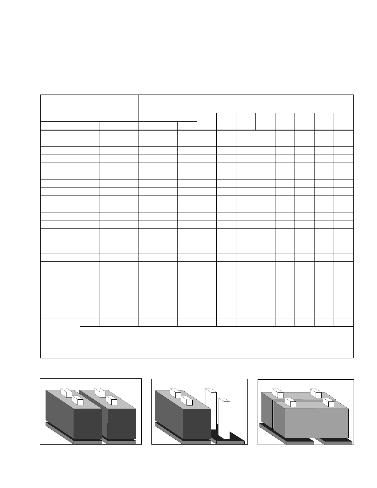
[Problem]
The bottom plate of the A4 (letter) size standard cassette is not lifted up eve n if the cassette is
inserted into the machine.
[Reason]
When installing the cassette, the slider [A] should
contact the Boss [B ] on t he base .
However [A] does not contact [B], because of the warp of
the cassette and the base plate of the machien.
Machine
Cassette
[A]
[Modification]
[B]
Temporary: Insert a washer (t=0.5mm, P/N: 07010030B) between the Boss [B] and the
Base plate of the machine
<Effective Date>
• H510-20: R8831000001~ • H5 10-30: 4671130001~
• H510-21: 6403100136 ~ • H510-40: U2731100001~
• H510-22: L4231000309~ • H510-51 : A1431000001~
• H510-27: 0831000146 ~ • H510-60: 6353110001~
Permanent: The heig ht of the Boss [B] (P/N: H081 35 61 ) has be en chan ge d fro m 6 mm to
7mm.
<Effective Date>
• From December 1st production
[Countermeasure]
• Install a plastic cap (which packed with this RTB) on to the Boss.
Use a glue for plastic.
or
• Insert a washer(P/N: 07010030B) or an M4 E-ring (P/N: 07200040E) between the Boss and
the Base Plate.
Page 5

Technical Bulletin No. CRO-004
SUBJECT: Paper not lifted up
PREPARED BY: A. Ishiyama
CHECKED BY:
CLASSIFICATION:
Action Required Revision of service manual
Troubleshooting Information only
Retrofit Information Other
To improve image quality, the OBM (mast er un it) has bee n mod ifie d, as shown below.
FROM: 1st T.S. Section
MODEL: CRO/ CS1
DATE:
Dec. 15. 1993
Paper path
When the paper passes over the maste r belt , to ne r sometimes does not transfer to the pape r
properly.
Therefore, the paper path inside the master has been changed, and the paper makes be tter
contact with the master.
This has been executed from October production.
Paper path
Page 6
Technical Bulletin No. CRO-005
SUBJECT: Hot Roller Down
PREPARED BY:H Yokoyama
CHECKED BY:
CLASSIFICATION:
Action Required Revision of service manual
Troubleshooting Information only
Retrofit Information Other
FROM: 2nd T.S. Section
MODEL:
CRO(Europe & Asia)
DATE:
Apr, 11th , 1994
<Problem>
Auto service call (Hot Roller Down) may occur during sta nd by mod e.
<Cause>
TRC (Triac)1 and/or 2 on the PSU may be damaged (short ed ) in the field by severe impulse
noise or power supply drop out. (The TRCs switch the ac power supply to the fusing lamp
on/off.)
This may cause continuou s power supply to the fusing lamp an d this will genarate the above
auto service call condition.
(There are two safety circuits for the power supply to the fusing lamp . The safety circuits cut the
power supply to the fusing lamp.)
<Modification>
Change the capacitors (C8 and C9) to th e surg e killers (10 0Ω +0.01µF) to increase the safety
margin against unstable ac power conditions in the field.
This will be effective from Feb. 1994 production.
Europe: H51 0 56 01B → C
Asia: H510 5602B → C
Page 7

Technical Bulletin No. CRO-006
SUBJECT: Rx problem from PC Fax modems
"Paper Size Error" indication
PREPARED BY: H.Yokoyama
CHECKED BY: S.Hamano
CLASSIFICATION:
Action Required Revision of service manual
Troubleshooting Information only
Retrofit Information Other
FROM: 2nd T.S. Section
MODEL:
CRO (Europe only)
DATE:
May 26th, 1994.
<Rx problem from PC Fax modems>
-ProblemCRO may not receive messages from PC Fax modems.
-CauseSome PC Fax modems can not recognize th e extended DIS frame (6 bytes) which was recently
recommended by CCITT.
-ActionAsk your customer to request th e sen de r (PC Fa x modem o wne r) to con tact a service engineer
to modify their software to solve th e pro ble m.
However we have prepared a coun te rmea sure ROM for this problem. This RO M should be
used only when the problem is not solved even if the sen der co nt acts the PC Fax board maker.
When this ROM is used, the DIS fra me is f ixed at 4 byt es so that the Fine Resolution
(8 X 15.4 l/mm) will not be used for transmittion.
<"Paper Size Error" indication>
-ProblemThe machine may display "Pape r Size Erro r" in the following conditions.
⋅ Machine Software : H5107130C, D or E
⋅ Printer Firmware : 930801 or 930319
-CauseSoftware of the machin e
-ActionWe have prepared a counterme asu re ROM fo r this problem.
Page 8
Technical Bulletin No. CRO-006
SUBJECT: Rx problem from PC Fax modems
"Paper Size Error" indication
There are two kinds of problem for the CRO, so the following is a summary of the
countermeasure ROMs.
Checksum
EB51 H5107130E 24 DEC. ’93 Norma l ma ss prod uction
E64F Same as above PC Fax problem
E387 Same as above "Paper Size Error"
E305 Same as above PC Fax problem and
Indication on the System
Parameter List
ROM
problem
"Paper Size Error"
problem
DATE:
May 26th, 1994.
Contents
The solution for the "Paper Size Error" indication problem will be introduced into the production
machines from Septembe r prod uction. (This is not fixed yet.)
Page 9

Technical Bulletin No. CRO-007
SUBJECT: Rx problem from PC Fax modems
"Paper Size Error" indication
PREPARED BY: H.Yokoyama
CHECKED BY: S.Hamano
CLASSIFICATION:
Action Required Revision of service manual
Troubleshooting Information only
Retrofit Information Other
FROM: 2nd T.S. Section
MODEL:
CRO (Asia only)
DATE:
July, 30, 1994.
<Rx problem from PC Fax modems>
-ProblemCRO may not receive messages from PC Fax modems.
-CauseSome PC Fax modems can not recognize th e extended DIS frame (6 bytes) which was recently
recommended by CCITT.
-ActionAsk your customer to request th e sen de r (PC Fa x modem o wne r) to con tact a service engineer
to modify their software to solve th e pro ble m.
However we have prepared a coun te rmea sure ROM for this problem. This RO M should be
used only when the problem is not solved even if the sen der co nt acts the PC Fax board maker.
When this ROM is used, the DIS fra me is f ixed at 4 byt es so that the Fine Resolution
(8 X 15.4 l/mm) will not be used for transmittion.
<"Paper Size Error" indication>
-ProblemThe machine may display "Pape r Size Erro r" in the following conditions.
⋅ Machine Software : H5107132C, D or E
⋅ Printer Firmware : 930801 or 930319
-CauseSoftware of the machin e
-ActionWe have prepared a counterme asu re ROM fo r this problem.
Please contact us if this prob lem happ en ed.
Page 10

Technical Bulletin No. CRO-008
SUBJECT: Rx problem from PC Fax modems
"Paper Size Error" indication
PREPARED BY: H.Yokoyama
CHECKED BY: S.Hamano
CLASSIFICATION:
Action Required Revision of service manual
Troubleshooting Information only
Retrofit Information Other
FROM: 2nd T.S. Section
MODEL:
CRO (USA only)
DATE:
July, 30, 1994.
<Rx problem from PC Fax modems>
-ProblemCRO may not receive messages from PC Fax modems.
-CauseSome PC Fax modems can not recognize th e extended DIS frame (6 bytes) which was recently
recommended by CCITT.
-ActionAsk your customer to request th e sen de r (PC Fa x modem o wne r) to con tact a service engineer
to modify their software to solve th e pro ble m.
However we have prepared a coun te rmea sure ROM for this problem. This RO M should be
used only when the problem is not solved even if the sen der co nt acts the PC Fax board maker.
When this ROM is used, the DIS fra me is f ixed at 4 byt es so that the Fine Resolution
(8 X 15.4 l/mm) will not be used for transmittion.
Please contact us if this prob lem happ en ed.
<"Paper Size Error" indication>
-ProblemThe machine may display "Pape r Size Erro r" in the following conditions.
⋅ Machine Software : CS1: H5117140 E, F or G
CRO: H5107140 D, E or F
⋅ Printer Firmware : 930801 or 930319
-CauseSoftware of the machin e
-ActionUse the following ROMs if this problem happened.
CS1: H5117140H
CRO: H5107 140G
The above ROMs will be used for massproduct ion from July production.
Page 11
Technical Bulletin No. CRO-009
SUBJECT: Printing Problem
PREPARED BY: Y.Okunishi
CHECKED BY: S.Hamano
CLASSIFICATION:
Action Required Revision of service manual
Troubleshooting Information only
Retrofit Information Other
[Problem]
Intermittent resideual image on receptions and reports when the unit has a PIF60 installed.
See below.
FROM: 2nd T.S. Section
MODEL:
CS1 America version
CRO America and Europ e
version
DATE:
July, 30th, 1994
[Cause]
Imcomplete switching at the clock to the fax and report page memory.
The clock to the printer page memory may be mixed with the clock to the fax and report page
memory sometimes.
[Countermeasu re]
The following ROMs will be changed.
<America>
H5117140G → H Programmed ROM - CS1 (From July production)
H5107140F → G Programmed ROM - CRO (From July production)
<Europe>
H5107130E → F Programmed ROM - EUR -CRO (From Aug. production)
H5107133B → C Programmed ROM - FRN -CRO (From Aug. production)
Page 12

Technical Bulletin No. CRO-010
SUBJECT: New CRO Information
PREPARED BY: M. Tasaka
CHECKED BY:
CLASSIFICATION:
Action Required Revision of service manual
Troubleshooting Information only
Retrofit Information Other
The New CRO will be launched from Sept. ’94 prod uct ion .
Please find the attached she et s which are described the additional information and the
difference of the parts numbers for the old CRO prod uct .
FROM: Over Sea T.S. Section
MODEL:
New CRO
DATE:
Aug 30th, 1994
Page 13

FAX 2500L/2600L/3500L
SERVICE MANUAL
Throughout this manual, the machin es are referrend to as follows:
CRO: FAX 2500L
CS1: FAX3500L
New CRO: FAX2600L
Page 14

Additional In formation for New CRO
The new CRO is a successor to the CRO. Theref ore, most features of the new CRO are the
same as the old CRO.
The differences betwe en the new CRO and old CRO are listed below.
1. Hardware
Items New CRO Old CRO
1.1 Specification
*Memory Capacity
*Paper Size
2.1.1 FCU
*SAF Memory Battery back-up(1H) No battery back-up
2. Software
Almost same as the CRO, excep t th e following
256 Kbytes
Letter , Legal
128 Kbytes
Letter
-The Direct Number Entry feature is available by pressin g the quick dial key(8 ).
This feature is programmed in the quick dia l key, as a de fault setting.
Part Number Information for FAX2600L Parts Catalo g
Item New CRO CRO
1. Cassette H081 3350 H081 3355 1-13- 8
2. Paper Size Detector Pin-LG H081 3388 — 1-13-28
3. PCB - FCU H081 6064 H510 6110 1- 5-49
4. Operators Manual H081 4444 H510 4300 1- 3- *
5. Op-Port ass’y H081 4725 H510 4200 1- 3-11
6. Standard Pin H081 3409 — 1-11-78
7. Film - Regist Guide Rail - Left H081 3521 — 1-13-17
8. Connector - Cover H081 3558 — 1-11-82
9. Quick Dial List: NA H081 4728 H510 4255 1- 3- 2
Parts Catalog Index
Page 15

Page 1/2
Technical Bulletin No. GENERAL-004
SUBJECT: Black bands/lines on the receive d cop y
PREPARED BY: H.Yokoyama
CHECKED BY:
CLASSIFICATION:
Action Required Revision of service manual
Troubleshooting Information only
Retrofit Information Other
FROM: 2nd T.S. Section
MODEL: USA only
CSO, CFO, CS1/CRO
DATE:
November 11th, 1993
[Problem]
On the received copies, bla ck ban ds or line s may
be printed, especially on the right hand side.
[Cause]
Toner or dust is attached to the charge corona wire.
[Modification]
The electric current of the charge coron a will be
increased to avoid applying uneren charg to the
master which is caused by a dirty corona wire.
Because of the increase of the ele ctric curre nt , th e
distance betwee n th e grid plate and the coro na
wire will be changed to keep the charge on the
master belt the same as before modification.
• H081 2870 → H081 2854 Eraser Ass’y
• H081 5030 → H081 5020 Power pack (CSO/CFO)
H510 5030 → H510 5020 Power pack (CRO/CS 1)
<Eraser Ass’y>
• The thickness of the clean ing blad e of the cleaner will be changed to incre ase the
cleaning ability (4mm → 5mm)
• The distance between the gride pla te and charg e wire will be cha ng ed (6mm → 8mm)
<Power pack>
• The range and initial value of the VRC (VR for the charg e coro na ) will be change d.
The above modification will ta ke pla ce fro m t he De cemb er 1st prod uction.
Page 16

Page 2/2
Technical Bulletin No. GENERAL-004
SUBJECT: Black bands/lines on the receive d cop y
DATE:
November 11th, 1993
[Countermeasure in the field]
The countermeasu re method depends on the CV (Cop y Volume) of the machine.
• If the CV is less than 400 sheets/month
Turn VRC on the power pack to the maximum (Turn the VR clockwise until it stops)
• If the CV is more than 400 sheet s/mo nth
Change the Eraser to the modified one and turn VRC on the power pack to the maximum.
Note:The increase in the powe r of VRC may de crease the life time of the master unit, so for
customers whose ACV/month is more than 400 sheets, the Erase r sh ould be change d.
[Request]
The essence of this problem is a dirty cha rge corona wire, so please do the follo wing
• When a sales or service person visits a customer (at PM or EM), clean the charge
corona wire with the built-in cleaner
• Advise the customer to clea n th e charge corona wire at a certain interval or if the
customer sees black bands/lines on the received copy.
Page 17
Page 1/2
Technical Bulletin No. GENERAL-005
SUBJECT: Black bands/lines on the receive d cop y
PREPARED BY: H.Yokoyama
CHECKED BY:
CLASSIFICATION:
Action Required Revision of service manual
Troubleshooting Information only
Retrofit Information Other
FROM: 2nd T.S. Section
MODEL: Europe, Asia
CSO, CFO, CRO
DATE:
Feb. 3rd, 1994
[Problem]
On the received copies, bla ck ban ds or line s may
be printed, especially on the right hand side.
[Cause]
Toner or dust is attached to the charge corona wire.
[Modification]
The electric current of the charge coron a will be
increased to avoid applying uneren charg to the
master which is caused by a dirty corona wire.
Because of the increase of the ele ctric curre nt , th e
distance betwee n th e grid plate and the coro na
wire will be changed to keep the charge on the
master belt the same as before modification.
• H081 2870 → H081 2854 Eraser Ass’y
• H081 5030 → H081 5020 Power pack (CSO/CFO)
H510 5050 → H510 5051 Power pack (CRO)
<Eraser Ass’y>
• The thickness of the clean ing blad e of the cleaner will be changed to incre ase the
cleaning ability (4mm → 5mm)
• The distance between the gride pla te and charg e wire will be cha ng ed (6mm → 8mm)
<Power pack>
• The range and initial value of the VRC (VR for the charg e coro na ) will be change d.
The above modification will take pla ce fro m t he Feb. 1st pro du ctio n.
Page 18

Page 2/2
Technical Bulletin No. GENERAL-005
SUBJECT: Black bands/lines on the receive d cop y
DATE:
Feb. 3rd, 1994
[Countermeasure in the field]
The countermeasu re method depends on the CV (Cop y Volume) of the machine.
• If the CV is less than 400 sheets/month
Turn VRC on the power pack to the maximum (Turn the VR clockwise until it stops)
• If the CV is more than 400 sheet s/mo nth
Change the Eraser to the modified one and turn VRC on the power pack to the maximum.
Note:The increase in the powe r of VRC may de crease the life time of the master unit, so for
customers whose ACV/month is more than 400 sheets, the Erase r sh ould be change d.
[Request]
The essence of this problem is a dirty cha rge corona wire, so please do the follo wing
• When a sales or service person visits a customer (at PM or EM), clean the charge
corona wire with the built-in cleaner
• Advise the customer to clea n th e charge corona wire at a certain interval or if the
customer sees black bands/lines on the received copy.
Page 19

Page 1/1
Technical Bulletin No. GENERAL-008
SUBJECT: Replacing th e toner cassette
PREPARED BY:H. Yokoyama
CHECKED BY:
CLASSIFICATION:
Action Required Revision of service manual
Troubleshooting Information only
Retrofit Information Other
The instruction of the operator’s manual for replacing the toner cassette (CTM) is wrong.
We will insert the errata sheet to the operator’s manual.
Wrong: 1. Switch off the machine.
Correct: Keep the power switch on whe n replacing the toner cassette.
FROM: 2nd T.S. Section
MODEL:
CSO, CFO, CRO, CS1
DATE:
April, 11th, 1994
Page 20

Page 1/1
Technical Bulletin No. GENERAL-009
SUBJECT: Vertical Black Lines
PREPARED BY: H.Yokoyama
CHECKED BY: S.Hamano
CLASSIFICATION:
Action Required Revision of service manual
Troubleshooting Information only
Retrofit Information Other
[Problem]
Vertical black lines appear on the printed image.
[Cause]
The toner may stick on the Hot Roller, Fusing Stripper, Thermisto r, and Thermostat and this
toner may damage the surf ace of th e Hot Roller. Then, during copying toner is transferred by
the scratched part of the roller to cause vertical bla ck lines on the print ed image .
FROM: 2nd T.S. Section
MODEL:
CSO, CFO, CRO, CS1
DATE:
Jury. 30, 1994
[Countermeasu re]
The material of the surface of the Hot Roller ha s bee n cha nged to pre ven t th e tone r from
sticking on the Roller by the following modification
H0812100D → E
Because of the ab ove mo dif ication, the vender has been changed.
[Effective S/N]
H081-24, 40, 46, 51, 54, 59, 60: Oct., 1993 ~
H510-20: R8831000609 ~
21, 22, 27, 30, 40, 51, 59, 60: Nov., 1993 ~
H082-20, 23, 30, 40, 51 , 59 , 60 : Nov. , 19 93 ~
H511-20, 21, 22, 27: Nov. , 19 93 ~
[Action]
Clean the Fusing Stripper, The rmisto r and Thermo stat and take out the tone r from them when
visit the customer.
Page 21

Leak Current
(On CFO / CS1 FCU)
Diode
COM
COM
Regulator
Technical Bulletin No. Multi-001
SUBJECT: Memory Back-up Battery
DATE:
Jan. 19, 1995
PREPARED BY: Y.Okunishi
CHECKED BY: S.Hamano
CLASSIFICATION:
Action Required Revision of service manual
FROM: 2nd T.S. Section
MODEL:
CSO, CFO, CS1, LHO
Troubleshooting Information only
Retrofit Information Other
[Symptom]
Stored documents in the me mory migh t be erase d when the main power goes down.
A power failure report is printed with the following informa tion.
• Memory Tx Files: Destination names or fax numbers are print ed.
• Substitute Recept ion Files: The Sender’s RTI or CSI is printed if they are pro gra mmed.
CSO rejects incoming messages without RTI or CSI because
of the factory setting.
• Memory Lock Files: Programmed Quick Numbers are printed.
[Cause]
Power loss from the memory back-up battery on FCU caused by excessive charge current, for
the following reasons.
(1) Leak current from Diode
The battery is charged after it is already
24V
24V
fully charged. This type of battery
is damaged if this occurs.
(2) Excessive charge voltage (CFO,
CS1,LHO) The target charge voltage
was 6.2V against 6. 4V or und er which is
recommended by the battery maker.
This margin was too small for this battery.
Zener
Diode
Battery
COM
[Modification]
See MB C Series-048A.
OUT
Page 22

Technical Bulletin No. Multi-001
SUBJECT: Memory Back-up Battery
[Action Taken]
1. Install the modified FCU to deal with customer claims.
2. Request technicians not to turn off the main power if a do cume nt is stored
in the memory.
[Note]
• Stored data other than docume nts is not erased even if the main power goes do wn.
DATE:
Jan. 19, 1995
Page 23

Technical Bulletin No. Multi-002
SUBJECT: Toner Spillage during Transportation
PREPARED BY: Y. Okunishi
CHECKED BY: M. Iwasa
CLASSIFICATION:
Action Required Revision of service manual
Troubleshooting Information only
Retrofit Information Preventive Action
Background: Machines have been sent to cu sto mers after pre-installation and sent back to the
service center for repair.
Problem: Toner had spread inside the machin e du ring transportation.
Cause: Toner leaked from the development unit, the toner ca rtrid ge , or somewhere
in the toner path during tran sportation.
Preparation for transportation:
(1) Transportation withou t he avy vibra tio n
(Example: A technician should carry the machine with care.)
• F/L series fax machines:
The development unit can be connected to a CTM with toner.
However, the toner path under the CTM must be covered by some
adhesive tape. See the attached illust rat ion.
• C series fax machines:
Follow RTB No. CSO-006
• Other order machines:
Follow (2) below.
FROM: 2nd T.S. Section
MODEL:
All laser plain paper fax
machines
DATE:
Jul. 15.1995
(2) Transportation with heavy vibration
(If a third party handles the transportation, follow this procedure.)
• F/L series fax machines:
Remove the development unit and the CTM fro m the machin e if toner
has been installed. They must not be delivered in the same box as the
machine, because they contain toner which may spill out. The toner
inside the machine must be clean ed away or th e toner path under the
CTM must be covered with tape.
• C series fax machines and others:
Remove the development unit and CTM (or Toner Cartridge) from
the machine if toner has been inst alle d, and clean the toner from
inside the machine.
The removed development unit and CTM must not be delivered
in the same box as the machine.
Page 24

Technical Bulletin No. Multi-002
SUBJECT: Toner Spillage during Transportation
Inside of FX6 and LSO
Drum
DATE:
Jul. 15.1995
Toner path
Note: Adhesion of the tap e sho uld not be strong. Otherwise, it may not be ta ken off
cleanly from the machine, or th e toner path may be damaged whe n it is t ake n
off.
Please request tape samples for th e FX6 and LSO from Ricoh.
Adhesive tape
Page 25

Technical Bulletin No. Multi-003
Page 1/2
SUBJECT: Harness for PFU
PREPARED BY: Y. Okunishi
CHECKED BY: M. Iwasa
CLASSIFICATION:
Action Required Revision of service manual
Troubleshooting Information only
Retrofit Information Other
Problem: The Paper Feed Unit may not work correctly.
Cause: Wires of the harness (H511 5528) from the FCU to the relay connect ors for the paper
feed unit (PFU) are not allocated properly.
Affected machines:
Fax 3500L S/N R8750600001 ~ R875070 0600
NRG9665 S/N 6355060620 ~ 6355060671
Savin Fax 3670 S/N 0950600001 ~ 0950700120
Fax 5600L S/N M2050600001 ~ M205070 0500
Lanier Fax 7550 S/N L7555060677 ~ L7555060780
Omnifax L540 S/N L5405060271 ~ L5405060330
FROM: 2nd T.S. Section
MODEL: Fax3500L(USA),
NRG9665(USA), Savin Fax3670
Fax5600L(USA),
Lanier Fax7550, Omnifax L540
DATE:
July 31, 1995
Action Required:
The harness should be checked before the start of th e PFU installation because the
FCU or the PFU PCB may become damaged.
Follow the attached proce du re be fo re PFU installation and change the harness
to a new one if it is bad.
Page 26

CN B
RTB No. Multi-003
Page 2/2
Harness Check Procedure
1. Remove the Rear Cover and Left Cover.
2. Unplug the connector CN28 on the FCU.
3. Unplug the connect ors CN A and CN B on the relay con ne ctor board located at the bot to m of
Main Frame.
Harness from FCU
(CN A & B)
Main Frame
Paper Feed Unit (PFU)
Relay connectors
Harness from PFU
4. Check the continuity of the harness pin by pin using a multimeter.
See below for what the correct allocation of all wires of the harness should be.
ABCDEFGHI
CN28 (to FCU)
J1234
5
6XX1234XX
CN A
(to PFU)
View from the side without the plastic cove r
Check the continuity of the following.
A of CN28 to 4 of CN B
⇓ ⇓
D of CN28 to 1 of CN B
E of CN28 to 6 of CN A
⇓ ⇓
J of CN28 to 1 of CN A
Page 27

Page 1/3
Technical Bulletin No. Multi - 004A
SUBJECT: Fusing Unit
PREPARED BY: Y.Okunishi
CHECKED BY: S.Fujii
CLASSIFICATION:
Action Required Revision of service manual
Troubleshooting Information only
Retrofit Information Other
A: "NOTE" is added to page 2/3.
SYMPTOM:
Background on received and copied documents.
Cause:
Hot Roller failure as a result of not changing the Cleaning Pad at the 10K PM.
Failure to change the Cleaning Pad results in dirty Strippers and Thermostat and
then Hot Roller failure.
As the machine warms up from the standby temperature to the fusing
temperature, it is exposed to slight overheating before the temperature levels
off. This leads to softening of the Teflon layer on the Hot Roller. As a result, the
Teflon layer peels off in the areas where the Strippers and other parts come in
contact with it. Dirty Strippers and Thermostat put more stress on the Hot Roller and
cause premature Hot Roller failure.
Also, the dirty Thermistor causes the Hot Roller to overherat and fail prematurely.
FROM: Quality Assurance Center
DATE:
Oct. 15, 1996
MODEL:
CSO, CRO, CS1, CFO,
CGO
A second cause can be a damaged (bent ) Thermistor from a previous service visit.
The damaged Thermistor causes the Hot Roller to overheat and fail prematurely.
SOLUTION:
Ricoh recommends replacing the Cleaning Pad at the 10K PM. However, this is
sometimes ignored. Realizing this, Ricoh will conduct the following modifications to
protect the Hot Roller from the failure mentioned above.
No. Old Part New Part Description Qty Used Interchangeability
1 H0812121 H0812123 Stripper Spring 2 → 2 X / O
H0812120 H5132119 Stripper
2
3
H0812137
H0815035
H0812141
03130080B
(Separation Pawl)
Thermistor Assembly
Thermistor
Bracket
Screw - M3x8
2 → 2 X / O
1 → 0
1 → 1
1 → 1
0 → 1
X / O as an
assembly
4 H0812100 H0819600 Hot Roller Kit 1 → 1 X / O
Page 28

Page 2/3
Technical Bulletin No. Multi - 004A
SUBJECT: Fusing Unit
DATE:
Oct. 15, 1996
Hot Roller Kit:
The hot rollers shipped from the SPC in Japan will be replaced by the
Hot Roller Kit in July.
This kit will be comprised of the following: Hot Roller, Cleaning Pad, Thermistor,
Thermistor Bracket, Screw, Strippers (2), Stripper Springs (2) and Installation Sheet.
The individual Hot Roller will be no longer available. The Cleaning Pad will
continue to be a Service Part.
Ricoh recommends change of the above modified parts and Cleaning Pad when the failed
Hot Roller is replaced with the new one.
NOTE
(A): Please refer to the following instructions and fix the cover to the fusing unit
and check that the harness is not pinched before installing the fusing unit in the
machine.
If the metal wire of the harness contacts the thermistor bracket, a no power
condition may occur. Please check the thermistor harness if this occurs.
Fusing Cover
(Bad)
Edge of the cover may damage
the harness
Edge
(Good)
Fusing Unit
Page 29

Installation Procedure for the Thermistor
1. Assemble the thermistor and the bracket
with the screw.
Bracket - Thermistor
H0812141
Thermistor - Fusing Unit
H0815035
Do not bendthis part
2. Install the
Thermistor Ass’y
( ✻ 4)
Thermistor - Fusing Unit
H0815035
Harness - Thermostat
(✻ 3)
Page 3/3
Thermostat - Fusing Unit
H0812134
Screw - M3 x 8
03130080B
(✻ 1)
Note: Set the projection on
the thermistor into
the hole in the bracket.
Note: ✻ 1 Place the thermostat harness under the part of the bracket.
✻ 2 Do not cross the thermostat harness and the thermistor harness.
✻ 3 Push the thermistor head (sensor) gently against the hot roller witha finger to make sure that the thermistor
head touches the hot roller surface. Do not push it strongly.
✻ 4 Do not bend the thermistor neck (spring plate) when installing or cleaning it .
If the thermistor is bent, replace it.
(✻ 2)
Bracket - Thermistor
H0812141
Stay - Fusing Unit - Upper
H0812175
Page 30

T
Model:
K105 (FAX4000L)
echnical
B
ulletin
Date:
15-Sep-97
No:
PAGE: 1/1
015
Subject:
From:
Classification:
The V.33 standard for 14.4 kbps modems has not been supported by FX4 and FX6MK2
because V.33 has been deleted from the ITU (CCITT) recommendations.
So, data transfer at 14.4 kbps speed between a FAX4000L which supports only V.33 and
products which support only V.17 will not be successful, and 9.6 kbps is the highest speed
for data transfer between them .
See the following list.
Only V.33 is supported V.33 and V.17 are
14.4 Kbps Modem
QAC 2nd Field Information Dept.
Troubleshooting
Mechanical
Paper path
Other ( )
K105 (FAX4000L) CFO, CS1, CGO FX6MK2, FX4
Part information
Electrical
Transmit/receive
supported
Prepared by:
Action required
Service manual revision
Retrofit information
Only V.17 is supported
Y.Okunishi
RC RE ASIA
✶✶
Page 31

T
Model:
General
echnical
B
ulletin
Date:
31-Oct-97
No:
PAGE: 1/3
011
Subject:
From:
Classification:
Check Items
The following function s for which the clock timer is used were checked to see whether or
not they will function correctly at 0:00 on Jan. 1, 2000.
1) Display and print of the date and time
2) Clock adjustment
3) Send later mode with memory and without memory
Year 2000 Problem
QAC 2nd Field Information Dept.
Troubleshooting
Mechanical
Paper path
Other ( )
The year must be changed to 2000 or 00 from 1999 or 99 and the date must be kept
correctly after the start of the year 2000.
The date and time can be adjusted after the start of the year 2000.
The dialling time must be at the set time after the start of the year 2000.
Part information
Electrical
Transmit/receive
Prepared by:
Action required
Service manual revision
Retrofit information
Y.Okunishi
4) Automatic re-transmission.
When a communication error happens, the machine dials the same destination again
automatically at an in terval. This must function correctly after the start of the year
2000.
5) Weekly timer and night timer
The energy saver mode (fusing unit) contro l must work correctly.
6) Displayed date after a power failure
The correct date must be kept by the battery back-up feature.
Models Checked
1) K50 series (FAX10, 20, 60, etc.)
2) K70 series (FAX90, 95, 105, etc.)
3) K90 series (FAX80, 85, 75, 86, etc.)
4) LE series (FAX08, 09, Phone fax for ATT, etc.)
5) B series (B1, RF810, FAX12, FAX300, etc.)
6) ZB series (FAX220, FAX240, Innfax, etc.)
7) BARBARA series (RF01, 02, 03, 05, 06, etc.)
8) OX series (FAX21, 22)
9) PF series (PF-1, PF-2)
10) A series (FAX500, 550, etc.)
Page 32

T
Model:
11) B60 series (FAX170, 180, etc.)
12) K100 series (FAX1000L, 1010L, etc.)
13) K105 series (FAX4000L, etc.)
14) K200 series (FAX7000L, etc.)
15) KV series (FAX2800L, 1200L, etc.)
16) C series (FAX3000L, 4500L, 5600L, etc.)
17) L80 (MV715)
18) I series (FAX800, 880, 680, etc.)
19) F\L series (FAX2700L, 4700L, MV310, etc.)
20) FX7, LX7 (FAX1700L, MV106, FAX1750MP, etc.)
21) L20 series (Aficio FX10)
General
echnical
B
ulletin
Date:
31-Oct-97
No:
PAGE: 2/3
011
Problems found
1) AF0 (FAX500, 550, etc.), CS0 (FAX3000L, 3100L, 3200L, etc.)
a) The day of week that appears on the display only in the clock adjustment mode
goes back to SUNDAY every time the clock is adjusted after the start of the
year 2000.
So, the programmed weekly timer does not work correctly.
If the clock is not adjusted after the start of the year 2000, the date and the day
of the week are kept correctly.
b) Clock adjustment is available only for years 91 through 99. The other years
cannot be set. (Month, day, and time can be adjusted.)
2) K200 (FAX7000L)
a) Clock adjustment is available only for years 88 through 99. The other years
cannot be set. (Month, day, and time can be adjusted.)
b) The send later mode does not function (no dialling occurs) if it passes the time
into the year 2000.
No report is printed and the remaining message in the memory is not cleared
automatically but it can be cleared by user operation.
c) Automatic re-transmission is not done if the year 2000 starts after the
transmission failure.
The remaining message in the memory is not cleared automatically but it can
be cleared by user operation.
d) The display year is returned back to 88 after a power failure after the start of
the year 2000.
Page 33

T
Model:
The other functions in these models work correctly.
Schedule for the countermeasure ROMs
1) AF0 (FAX500, 550, etc.), CS0 (FAX3000L, 3100L, 3200L, etc.)
2) K200 (FAX7000L)
General
In January 1998.
In April 1998.
echnical
B
ulletin
Date:
31-Oct-97
No:
PAGE: 3/3
011
RC RE ASIA
Page 34

T
echnical
B
ulletin
MB Correction
Reissue date: 15-Nov-97
The items in bold italic have been corrected or added.
Model:
General
Date:
31-Oct-97
No:
PAGE: 1/3
011
A
Subject:
From:
Classification:
Check Items
The following functions for which the clock timer is used were checked to see whether or
not they will function corr ectly at 0:00 on Jan. 1, 2000.
1) Display and print of the date and time
2) Clock adjustment
3) Send later mode with memory and without memory
Year 2000 Problem
QAC 2nd Field Inf or mation Dept .
Troubleshooti ng
Mechanical
Paper path
Other
The year must be changed to 2000 or 00 from 1999 or 99 and the date must be kept
correctly after the year 2000.
The date and time can be adjusted after the time becomes the year 2000.
The calling time must be the set time after the time becomes the year 2000.
(Info only)
Part information
Electri cal
Transmit/receive
Prepared by:
Action required
Service manual revision
Retrofi t information
Y.Okunishi
4) Automatic re-transmission.
When the communication error happens, the machine calls to the same destination
again automatically with an interval. This must function correctly after the time
becomes the year 2000.
5) Weekly timer and night timer
The energry saver mode (heater) control must work correctly.
6) Displayed date after a power failure
The correct date must be kept by the battery.
Models Checked
1) K50 series (FAX10, 20, 60, etc.)
2) K70 series (FAX90, 95, 105, etc.)
3) K90 series (FAX80, 85, 75, 86, etc.)
4) LE series (FAX08, 09, Phone fax for ATT, etc.)
5) B series (B1, RF810, FAX12, FAX300, etc.)
6) ZB series (FAX220, FAX240, Innfax, etc.)
7) BARBARA series (RF01, 02, 03, 05, 06, etc.)
Page 35

T
Model:
8) OX series (FAX21, 22)
9) PF series (PF-1, PF-2)
10) A series (FAX500, 550, etc.)
11) B60 series (FAX170, 180, etc.)
12) K100 series (FAX1000L, 1010L, etc.)
13) K105 series (FAX4000L, etc.)
14) K200 series (FAX7000L, etc.)
15) KV series (FAX2800L, 1200L, etc.)
16) C series (FAX3000L, 4500L, 5600L, etc.)
17) L80 (MV715)
18) I series (FAX800, 880, 680, etc.)
19) F\L series (FAX2700L, 4700L, MV310, etc.)
General
echnical
B
ulletin
Date:
31-Oct-97
No:
PAGE: 2/3
011
A
20) FX7, LX7 (FAX1700L, MV106, FAX1750MP, etc.)
21) L20 series (Aficio FX10)
Problem found
Most of the models except the following model s, will not experience any problems.
1) AFO (FAX 500/550/580, NGR 9620, Infotec 3301/3305, Nashua F492)
CSO (FAX 3000/3100/3200, NGR 9660/9661/9662, Omnifax L40/41,
Savin FAX 3660/3620, Infotec 3660)
CS1 (FAX 3500L,NRG 9665, Omnifax L46, Savin FAX 3670)
CRO (FAX 2500L/2600L, NRG 9650, Omnifax L42, Savin FAX 3630, Infotec 3661)
a) The day of week, that appears on the display only in the clock adjustment
mode, is returned back to SUNDAY every time when the clock adjustment is
done after the time becomes the year 2000.
So, the programmed weekly timer does not work correctly.
have the weekly timer.)
If the clock adjustment is not done after the time becomes the year 2000, the
date and the day of week is kept correctly.
(AFO’ s do not
b) Clock adjustment is available only for the year 91 through 99. The other years
cannot be set. (Month, day and time can be adjusted.)
Page 36

T
Model:
2) K200 (FAX7000L)
General
a) Clock adjustment is available only for the years 88 through 99. The other years
cannot be set. (Month, day and time can be adjusted.)
b) The send later mode does not function (no calling happens) if it passes the
time into the year 2000.
No report is printed and the rest message in the memo ry is not cleared
automatically but it is cleared by the user operation.
c) Automatic re-transmission is not done if the time becomes the year 2000 in the
interval after the transmission failure.
The rest message in the memory is not cleared automatically but it is cleared
by the user operation.
d) The display year is returned back to 88 after the power failure after the time
becomes the year 2000.
echnical
B
ulletin
Date:
31-Oct-97
No:
PAGE: 3/3
011
A
The other functions in these models work correctly.
Schedule of the countermeasure ROMs
1) AFO, CSO, CS1, CRO:
In January 1998.
2) K200(FAX7000L):
In April 1998.
RC RE ASIA
∗ ∗ ∗
Page 37

T
echnical
B
ulletin
MB Correction
Reissue date: 15-Jan-98
The items in bold italic have been corrected or added.
PAGE: 1/3
Model:
Subject:
From:
Classification:
Check Items
The following function s for which the clock timer is used were checked to see whether or
not they will function correctly at 0:00 on Jan. 1, 2000.
1) Display and print of the date and time
2) Clock adjustment
3) Send later mode with memory and without memory
General
Year 2000 Problem
QAC 2nd Field Information Dept.
Troubleshooting
Mechanical
Paper path
Other (Info only)
The year must be changed to 2000 or 00 from 1999 or 99 and the date must be kept
correctly after the year 2000.
The date and time can be adjusted after the time becomes the year 2000.
The calling time must be the set time after the time becomes the year 2000.
Part information
Electrical
Transmit/receive
Date:
15-Jan-98
Prepared by:
Action required
Service manual revision
Retrofit information
No:
Y.Okunishi
011
B
4) Automatic re-transmission.
When the communication error happens, the machine calls to the same destination
again automatically with an interval. This must function co rrectly after the time
becomes the year 2000.
5) Weekly timer and night timer
The energry saver mode (h eater) control must work correctly.
6) Displayed date after a power failure
The correct date must be kept by the battery.
Models Checked
1) K50 series (FAX10, 20, 60, etc.)
2) K70 series (FAX90, 95, 105, etc.)
3) K90 series (FAX80, 85, 75, 86, etc.)
4) LE series (FAX08, 09, Phone fax for ATT, etc.)
5) B series (B1, RF810, FAX12, FAX300, etc.)
6) ZB series (FAX220, FAX240, Innfax, etc.)
7) BARBARA series (RF01, 02, 03, 05, 06, etc.)
Page 38

T
echnical
B
ulletin
PAGE: 2/3
Model:
8) OX series (FAX21, 22)
9) PF series (PF-1, PF-2)
10) A series (FAX500, 550, etc.)
11) B60 series (FAX170, 180, etc.)
12) K100 series (FAX1000L, 1010L, etc.)
13) K105 series (FAX4000L, etc.)
14) K200 series (FAX7000L, etc.)
15) KV series (FAX2800L, 1200L, etc.)
16) C series (FAX
17) L80 (MV715)
18) I series (FAX800, 880, 680,
19) F\L series (FAX2700L,
20) FX7, LX7 (FAX1700L, MV106, FAX1750MP, etc.)
General
2500L
,3000L,
3700L
3500L
MV74
, 4500L, 5600L, etc.)
, etc.)
, 4700L, MV310, etc.)
Date:
15-Jan-98
No:
011
B
21) L20 series (Aficio FX10)
Problem found
Most of the models except the following models, will not experience any problems.
1) AFO (FAX 500/550/580,
CSO (FAX 3000/3100/3200,
Savin FAX 3660/3620, Infotec 3660)
CS1 (FAX 3500L,NRG 9665, Omnifax L46, Savin FAX 3670)
CRO (FAX 2500L/2600L, NRG 9650, Omnifax L42, Savin FAX 3630, Infotec 3661)
a) The day of week, that appears on the display only in the clock adjustment
mode, is returned back to SUNDAY every time when the clock adjustment is
done after the time becomes the year 2000.
So, the programmed weekly timer does not work correctly. (AFO’ s do not
have the weekly timer.)
If the clock adjustment is not done after the time becomes the year 2000, the
date and the day of week is kept correctly.
b) Clock adjustment is available only for the year 91 through 99. The other years
cannot be set. (Month, day and time can be adjusted.)
9620, Infotec 3301/3305, Nashua F492)
NRG
9660/9661/9662, Om nifax L40/41,
NRG
Page 39

T
echnical
B
ulletin
PAGE: 3/3
Model:
2) K200 (FAX7000L)
The other functions in these models work correctly.
General
a) Clock adjustment is available only for the years 88 through 99. The other years
cannot be set. (Month, day and time can be adjusted.)
b) The send later mode does not function (no calling happens) if it passes the
time into the year 2000.
No report is printed and the rest message in the memory is not cleared
automatically but it is cleared by the user operation.
c) Automatic re-transmission is not done if the time becomes the year 2000 in the
interval after the transmission failure.
The rest message in the memory is not cleared automatically but it is cleared
by the user operation.
d) The display year is returned back to 88 after the power failure after the time
becomes the year 2000.
Date:
15-Jan-98
No:
011
B
Schedule of the countermeasure ROMs
1) AFO, CSO, CS1, CRO:
In January 1998.
2) K200(FAX7000L):
In April 1998.
RC RE ASIA
∗ ∗ ∗
Page 40

T
Model:
General
echnical
B
ulletin
Date:
15-Apr-98
No:
PAGE: 1/3
014
Subject:
From:
Classification:
The year 2000 issue was explained in RTB No. General-011B.
That RTB explains only the technical matters of what will happen after the year 2000 in
some models, and the countermeasures.
At this time, we would explain how to talk with customers about the year 2000 issues
related to fax machines.
Basically, we can say to the customers that there is no major issue reated to basic
operation after the year 2000, and they don't need to take any preventative action before
the year 2000.
The only thing that the customers need to know is that the following operations will be
changed after the year 2000.
Action Plan for the Year 2000 Issues
QAC Field Inf or mation Dept .
Troubleshooti ng
Mechanical
Paper path
Other (Info only)
Part information
Electri cal
Transmit/receive
Prepared by:
Action required
Service manual revision
Retrofi t information
Y.Okunishi
1. AF0 (FAX 500/550/580, NRG 9620, Infotec 3301/3305, Nashua F492)
CS0 (FAX 3000/3100/3200, NRG 9660/9661/9662, Omnifax L40/41,
Savin FAX 3660/3620, Infotec 3660)
CS1 (FAX 3500L,NRG 9665, Omnifax L46, Savin FAX 3670)
CR0 (FAX 2500L/2600L, NRG 9650, Omnifax L42, Savin FAX 3630, Infotec 3661)
First, please do not forget to inform the customers that they don't need to do anything if
they do not go into the clock adjustment mode.
A) Adjustment of the year
A-1) For the year 2000
①Set the clock to 11:59 PM (or 23:59) on December 31 1999, and wait for one minute.
②The year changes to 2000 automatically, then set the current time.
(Do not change the year.)
A-2) For the year 2001
③After the above step ①, set the clock to 11:59 PM (or 23:59) on December 31 2000, and
wait for one minute.
④The year changes to 2001 automatically, then set the current time.
(Do not change the year.)
A-3) For years 2002 and later, repeat the same procedure as above.
Page 41

T
Model:
General
echnical
B
ulletin
Date:
15-Apr-98
No:
PAGE: 2/3
014
B) Adjustment of the weekly timer (Heater timer)
This is only for customers who use the weekly timer. (We do not think that many
customers are using this function.)
Please recommend adjusting the timer on Sunday if the customer can do it.
If they cannot do it on Sunday, the ROM should be changed to the new one.
The new ROM includes the countermeasure for the above A) also.
2. K200 (FAX7000L)
A) Adjustment of the year
First, please do not forget to inform the customers that they don't need to do anything if
they do not go into the clock adjustment mode.
A-1) For the year 2000
Set the clock to 11:59 PM (or 23:59) on December 31 1999, and wait for one minute.
①
The year changes to 2000 automatically, then set the current time.
②
(Do not change the year.)
A-2) For the year 2001
Except AF0
••••
After the above step ①, set the clock to 11:59 PM (or 23:59) on December 31 2000,
③
and wait for one minute.
The year changes to 2001 automatically, then set the current time.
④
(Do not change the year.)
A-3) For years 2002 and later
Repeat the same procedure as above.
If the customer switches off the machine after the year 2000, the year displayed re turns to
1988. In this case, follow the above procedure to adjust the clock.
B) Send later mode
Please notify the customer that they should not use send later mode on December 31st
1999, if the transmission will be done on the next day.
If the customer cannot guarantee that they will follow this advice, the ROM should be
changed.
Page 42

T
Model:
Schedule of the countermeasure ROMs
1) AFO, CSO, CS1, CRO:
2) K200 (FAX7000L):
Both are delayed.
∗
General
In May 1998.
In May 1998.
echnical
B
ulletin
Date:
15-Apr-98
No:
PAGE: 3/3
014
RC RE ASIA
∗ ∗ ∗
Page 43

RICOH Technical
Model:
LSO, CRO, CS1, AFO, AF2, K200
Bulletin
Date:
31-May-98
No:
PAGE:
Multi - 008
1/8
Subject:
From:
Classification:
Attached please find the list of the ROMs for the year 2000 problem and the procedure for
making R200 ROMs from the ROM file s.
Note:
Please refer to RTB nos. General 11 and 14 for details.
·
8 ROMs for the K200 are combined in one file.
·
ROMs for the year 2000 problem
QAC Field Information Dept.
Troubleshooting
Mechanical
Paper path
Other ( )
Part information
Electrical
Transmit/receive
Prepared by:
Action required
Service manual revision
Retrofit information
Y.Okunishi
RC RE ASIA
* * *
Page 44

RICOH Technical
Model:
LSO, CRO, CS1, AFO, AF2, K200
Bulletin
Date:
31-May-98
No:
PAGE:
Multi - 008
2/8
ROMs for the year 2000 May 29, 1998
Y.Okunishi
Product
Code
CSO H0817138 yes CSO7138 8552 c30usa H081-20 3000L RICOH US 91/12 93/4 16,747 2M ROM (1ROM/unit)
CS1 H5117150B yes CS17150B 6A91 c31usa H511-20 3500L RICOH US 93/6 96/3 31,766
CR0 H5107121B yes CRO7121B 23AB c60usa H510-20 2500L RICOH US 93/5 95/4 26,535
New ROM
No.
H0817136A yes CSO7136S 77A7
H0817139E yes CSO7139E 3C77 c30tel 28 L40 L41 Omnifax US 92/1 93/5 5,181
H0817124A yes CSO7124A 0772 c30eur 40 3000L 3000L RICOH Europe 92/3 95/11 37, 716
H0817123A no CSO7123A 0078 c30fra 70 3000LF RICOH France 93/4 95/9 393
H0817121A yes CSO7121A FA57 c30hcs 30 3660 Infotec Europe 92/10 94/8 15,528
H0817122A yes CSO7122A D225 c30asi 51 3000L RICOH Asia 92/3 96/10 18,523
H0817140M yes CSO7140M 859C c30tai 23 3000L RICOH Taiwan 92/3 95/11
H0817128B no CSO7128B E8C5 c30chi 54 3000L RICOH China 93/7 95/11
H0817159N yes CSO7159N C3CE c30opt
Test File name Check
sum
ROM Code Model code Model Brand Area Sold from Sold by No. of sold
23 3200L 91/12 95/11 18, 242
24 3100L 93/2 95/2 21,863
21 9660 NRG 92/3 92/7 71
22 9661 92/3 94/ 2 1,651
26 3660 SAVIN 92/2 93/4 1,372
27 3620 92/1 93/ 4 1,917
TOTAL
c30usa
•
H151-65•SW:HCS•,H151-
73(•:RE),H151-83(•:GES)
25 2600L RICOH US 94/9 95/3
29 L41 92/1 93/5 8,008
TOTAL
46 3000L RICOH Switzerland 92/10 95/6 4,179
60 9660 NRG Europe 93/3 95/8 15,659
TOTAL
80 92/4 95/9 6,206
90 9660F NRG 92/4 95/9 2,164
TOTAL
59 9660 NRG 94/3 96/4 2,837
55 - Ricoh Korea ?
TOTAL
Option Europe ? Language Kit
21 9669 NRG 93/6 95/9 700
22 L46 Omnifax 93/6 95/12 11,472
27 3670 SAVIN 93/7 95/9 3,106
3/8
21 9650 NRG 93/7 95/7 832
TOTAL
units
61,863
8,000
13,189
57,554
8,763
36,888
1,251
981
47,044
Note
Page 45

RICOH Technical
H5107120B yes CRO7120B F5BF c60eur 30 3661 Infotec Europe 93/9 94/9 5,564
H5107123B yes CRO7123B 0E88 c60fra 33 3661F Infotec France 94/4 95/9 242
H5107132G yes CRO7132G 37F5 c60asi 51 2500L RICOH Asia 93/12 96/1 5,955
H5107131B yes CRO7131B 23A3 c60tai 53 2500L RICOH Taiwan 94/10 97/6
AFO H0847130K yes AFO7130K D8D3 a20usa H084-20 500 RICOH Taiwan 92/4 93/4
H0847140L yes AFO7140L 6B6A a20eur 44 500 RICOH Europe 91/8 94/10
H0847142H no AFO7142H 94D0 a20fra 83 500 RICOH France 92/4 94/3
H0847143L yes AFO7143L 350F a20hcs 34 3301 Infotec Europe 91/8 95/4
H0847141L yes AFO7141L 3F13 a20asi 51 500 RICOH Asia 91/10 96/11 13,696
H0847150K yes AFO7150K 2A40 a20opt
AF1 H0857135B yes AF17135B FCDF a21chi H085-54 580 RICOH China 93/ 8 96/5
AF2 H0867130K yes AF27130K 9BDF a22usa 20 550 RICOH US 92/1 96/2
H0867140L yes AF27140L 3C35 a22eur 44 550 RICOH Europe 91/8 95/3 10,824
H0867142H checkingAF27142H 583D a22fra 73 3305 Infotec France - - 0 RIF is checking the
H0867143L yes AF27143L 0CE0 a22hcs 34 3305 Infotec Europe 91/8 95/9
H0867141L yes DAD8 a22asi 51 550 RICOH Asia 92/2 96/2 12,181
H0867131A yes AF27131A 9BC3 a22tai 53 550 RICOH Taiwan 94/8 96/2
H0867150L yes AF27150L E725 a22opt
Bulletin
22 L42 Omnifax 93/9 95/3 6,848
27 3630 SAVIN 93/7 95/3 2,136
40 2500L RICOH 93/9 95/7 11,418
60 9650 NRG 93/9 95/8 5,632
43 2500LF RICOH 93/10 95/9 2,012
63 9650F NRG 93/10 95/9 931
59 9650 NRG 94/1 95/9 1,107
56 500 RICOH Vietnam 92/11 94/5 1,650 KD
H15146(•:RICOH),H
151-54(SW:HCS)
90 9620 NRG 92/4 93/9 1,446
83 550 RICOH 95/4 95/9 100
93 9620 NRG 92/4 94/9 170
59 Nashua Asia 92/2 96/1 1,662
H15147(•:RICOH),H
15155(SW:HCS),H15193(•:NASHUA)
- Option Europe ? Language K i t
- Option Europe ? Language Kit
PAGE:
TOTAL
TOTAL
TOTAL
TOTAL
TOTAL
TOTAL
TOTAL
TOTAL
36,351
22,614
3,185
7,062
777
365
6,817
1,231
2,892
15,346
5,040
14,934
12,270
ROM.
270
6,583
13,843
109
Page 46

RICOH Technical
Bulletin
PAGE:
4/8
K200 H0087260J
H0087261J
H0087262J
H0087263J
H0087264J
H0087265J
H0087266J
H0087267J
H0087270F
H0087271F
H0087272F
H0087273F
H0087274F
H0087275F
H0087276F
H0087277F
H0087320F
H0087321F
H0087322F
H0087323F
H0087324F
H0087325F
H0087326F
H0087327F
H0087280H
H0087281H
H0087282H
H0087283H
H0087284H
H0087285H
H0087286H
H0087287H
H0087330H
H0087331H
H0087332H
H0087333H
H0087334H
H0087335H
H0087336H
H0087337H
H0087290C
H0087291C
H0087292C
H0087293C
H0087294C
H0087295C
H0087296C
H0087297C
yes H0087260 FC1E
EBE0
B88F
08B2
7AA0
C2F0
28D7
CE5E
yes H0087270 451C
78BA
3FA2
C44F
7B14
4DA3
7C16
380B
yes H0087320 4527
7967
3FA2
C44F
7B14
4DA3
7C16
380B
yes H0087280 1956
CB16
4E46
C3F4
799D
33A8
3EE5
6478
yes H0087330 1D20
64B7
4FAF
D4A1
7830
1EBB
C591
854A
yes H0087290 4A5D
5B24
416A
C54D
8882
683D
D331
E525
USA 20 7000L RICOH US 89/9 95/6
GMN 30 7000L RICOH Germany 89/10 93/7
GMN 40 6765 Infotec Germany 89/9 90/8
ENG 41 7000L RI COH UK 89/10 94/8
ENG 31 6765 Infotec UK 89/10 92/12
ITY 42 7000L RICOH Italy 89/10 91/10
790
1M ROM (8 ROMs/unit)
119
180
85
125
29
Page 47

RICOH Technical
H0087340C
H0087341C
H0087342C
H0087343C
H0087344C
H0087345C
H0087346C
H0087347C
H0087300E
H0087301E
H0087302E
H0087303E
H0087304E
H0087305E
H0087306E
H0087307E
H0087350E
H0087351E
H0087352E
H0087353E
H0087354E
H0087355E
H0087356E
H0087357E
H0087310H
H0087311H
H0087312H
H0087313H
H0087314H
H0087315H
H0087316H
H0087317H
H0087360H
H0087361H
H0087362H
H0087363H
H0087364H
H0087365H
H0087366H
H0087367H
yes H0087340 4A68
5BD1
416A
C54D
8882
683D
D331
E525
yes H0087300 4A2A
3680
403B
9F7C
8900
DB80
6C4A
1B91
yes H0087350 4A35
372D
403B
9F7C
8900
DB80
6C4A
1B91
yes H0087310 196E
CB4C
4E46
C3F4
799A
3385
3EE5
6478
yes H0087360 1D38
64ED
4FAF
D4A1
782D
1E98
C591
854A
ITY 32 6765 Infotec Italy 89/10 92/9
FRN 43 7000L RICOH France 89/10 92/3
FRN 33 6765 Infotec France 90/7 91/3
UNV 44 7000L RICOH Europe/Asia 89/9 94/1
UNV 34 6765 Infotec Europe 90/1 92/11
Bulletin
PAGE:
5/8
41
137
156
387
38
END
Page 48

RICOH Technical
Bulletin
ROM writing procedure for K200 ROMs
1. ROM Writing
This will vary depending on the ROM writer buffer capacity.
This is an example with a buffer RAM capacity of 512KB.
During the first load, 512KB is sent.
During he first load, 0H~7FFFFH can be loaded.
During the second, 800000H~FFFFFH can be loaded.
Since the K200 is 1MB, the sending is completed after 512KB worth has been sent
twice.
First Time
1-1) Transfer to the ROM writer.
Motorola-S Format
Receiving location address 00000000
Send/Receive buffer RAM start 00000000
Sending buffer RAM end Device capacity
1-2) Program on the ROM
Set program 16-bit series
Device Count 4
Device Start 00000000
Buffer RAM Start 00000000
Data Type BIGENDIAN
PAGE:
6/8
Second Time
2-1) Transfer to the ROM writer.
Motorola-S Format
Receiving location address 00080000
Send/Receive buffer RAM start 00000000
Sending buffer RAM end Device capacity
2-2) Program on the ROM
Set program 16-bit series
Device Count 4
Device Start 00000000
Buffer RAM Start 00000000
Data Type BIGENDIAN
When the buffer RAM capacity is 1MB, the RAM writing is as follows.
1MB can be sent during the first load.
OH~FFFFFH can be loaded.
Since the K200 is 1MB, it can be transferred all at once.
Page 49

RICOH Technical
First Time
1-1) Transfer to the ROM writer.
Motorola-S Format
Receiving location address 00000000
Send/Receive buffer RAM start 00000000
Sending buffer RAM end Device capacity
1-2) Program on the ROM
Set program 16-bit series
Device Count 4
Device Start 00000000
Buffer RAM Start 00000000
Data Type BIGENDIAN
Second Time
2-1) Transfer to the ROM writer.
Since 1MB can be sent the first time, this is not necessary.
2-2) Program on the ROM
Set program 16-bit series
Device Count 4
Device Start 00000000
Buffer RAM Start 00080000
Data Type BiGENDIAN
Bulletin
PAGE:
7/8
ROM locations (Top view of MBU)
3-8 (3’) 3-0 (4’)
2-8 (1’) 2-0 (2’)
1-8 (3) 1-0 (4)
0-8 (1) 0-0 (2)
() The number in the parentheses is the ROM writer socket number.
[‘] The second time is indicated.
The ROM part numbers start from 0-8.
(Ex: For the FAX7000L(US), 0-8:H0087260, 3-0:H0087267)
Page 50

RICOH Technical
Check Sum Chart
ROM location
Model
K200USA F C1E EBE0 B88F 08B2 7AA0 C2F0 28D7 EC5E
K200GMN-R 451C 78BA 3FA2 C44F 7B14 4DA3 7C16 380B
K200G<M-K 4527 7967 3FA2 C44F 7B14 4DA3 7C16 380B
K200ENG-R 1956 CB16 4E46 C3F4 799D 33A8 3EE5 6478
K200ENG-K 1D20 64B7 4FAF D4A1 7830 1EBB C591 854A
K200ITY-R 4A5D 5B24 416A C54D 8882 683D D 331 E525
K200ITY-K 4A68 5BD1 416A C54D 8882 683D D331 E525
K200FRN-R 4A2A 3680 403B 9F7C 8900 DB80 6C4A 1B91
K200FRN-K 4A35 372D 403B 9F7C 8900 DB80 6C4A 1B91
K200UNV-R 196E CB4C 4E46 C3F4 799A 3385 3EE5 6478
K200UNV-K 1D38 64ED 4FAF D4A1 782D 1E98 C591 854A
R: Ricoh, K : Kalle (Infotec)
0-8 0-0 1-8 1-0 2-8 2-0 3-8 3-0
Bulletin
PAGE:
8/8
Page 51

T
echnical
B
ulletin
RTB Correction
Reissue date: 30-Jun-98
The items in bold italic have been corrected or added.
Model:
General
Date:
15-Jan-98
No:
PAGE: 1/3
C
011
Subject:
From:
Classification:
Check Items
The following function s for which the clock timer is used were checked to see whether or
not they will function correctly at 0:00 on Jan. 1, 2000.
1) Display and print of the date and time
2) Clock adjustment
3) Send later mode with memory and without memory
Year 2000 Problem
QAC 2nd Field Information Dept.
Troubleshooting
Mechanical
Paper path
Other (Info only)
The year must be changed to 2000 or 00 from 1999 or 99 and the date must be kept
correctly after the year 2000.
The date and time can be adjusted after the start of the year 2000.
The calling time must be the set time after the start of the year 2000.
Part information
Electrical
Transmit/receive
Prepared by:
Action required
Service manual revision
Retrofit information
Y.Okunishi
4) Automatic re-transmission.
When a communication error occu rs, the machine calls the same destination again
automatically after an interval. This must function correctly after the start of the year
2000.
5) Weekly timer and night timer
The energy saver mode (heater) control must work correctly.
6) Displayed date after a power failure
The correct date must be kept by the battery.
Models Checked
1) K50 series (FAX10, 20, 60, etc.)
2) K70 series (FAX90, 95, 105, etc.)
3) K90 series (FAX80, 85, 75, 86, etc.)
4) LE series (FAX08, 09, Phone fax for ATT, etc.)
5) B series (B1, RF810, FAX12, FAX300, etc.)
6) ZB series (FAX220, FAX240, Innfax, etc.)
7) BARBARA series (RF01, 02, 03, 05, 06, etc.)
Page 52

T
echnical
B
ulletin
PAGE: 2/3
Model:
8) OX series (FAX21, 22)
9) PF series (PF-1, PF-2)
10) A series (FAX500, 550, etc.)
11) B60 series (FAX170, 180, etc.)
12) K100 series (FAX1000L, 1010L, etc.)
13) K105 series (FAX4000L, etc.)
14) K200 series (FAX7000L, etc.)
15) KV series (FAX2800L, 1200L, etc.)
16) C series (FAX2500L,3000L, 3500L, 4500L, 5600L, etc.)
17) L80 (MV715)
18) I series (FAX800, 880, 680, MV74, etc.)
19) F\L series (FAX2700L, 3700L, 4700L, MV310, etc.)
20) FX7, LX7 (FAX1700L, MV106, FAX1750MP, etc.)
21) L20 series (Aficio FX10)
General
Date:
15-Jan-98
No:
011
C
22) K10 series (FX120, Rapicom120, FX210/230, Rapicom210/230, etc.)
23) K20 series (FX5000, Rapicom5000, etc.)
24) K60 series (FAX610, Rapicom610, etc.)
25) K83 series (FAX830, Rapicom830, etc.)
26) FR4, FR6 (FAX4800L, FAX3800L, etc.)
Problem found
Most models, except the following models, will not experience any problems.
1) AFO (FAX 500/550/580, NRG 9620, Infotec 3301/3305, Nashua F492)
CSO (FAX 3000/3100/3200, NRG 9660/9661/9662, Omnifax L40/41,
Savin FAX 3660/3620, Infotec 3660)
CS1 (FAX 3500L,NRG 9665, Omnifax L46, Savin FAX 3670)
CRO (FAX 2500L/2600L, NRG 9650, Omnifax L42, Savin FAX 3630, Infotec 3661)
a) The day of week, that appears on the display only in the clock adjustment
mode, is returned back to SUNDAY whenever the clock adjustment is done
after the start of the year 2000.
So, the programmed weekly timer does not work correctly. (AFO’ s do not
have the weekly timer.)
If the clock adjustment is not done after the start of the year 2000, the date and
the day of week is kept correctly.
b) Clock adjustment is available only for the year 91 through 99. The other years
cannot be set. (Month, day and time can be adjusted.)
Page 53

T
echnical
B
ulletin
PAGE: 3/3
Model:
2) K200 (FAX7000L)
3) K60 series (FAX610, Rapicom610, Infotec6550)
General
a) Clock adjustment is available only for the years 88 through 99. The other years
cannot be set. (Month, day, and time can be adjusted.)
b) The send late r mode does not function (no calling happens) if it passes the time
into the year 2000.
No report is printed. The message in the memory is not cleared automatically
but must be cleared by user operation.
c) Automatic re-transmission is not done if the year 2000 starts in the interval after
the transmission failure.
The message in the memory is not cleared automatically but must be cleared
by user operation.
d) The display year is returned back to 88 after a power failure after the start of
the year 2000.
K83 series (FAX830, Rapicom830, Infotec6750)
Date:
15-Jan-98
No:
011
C
a) The day of week is not displayed correctly after the start of the year 2000.
b) The send later mode does not function (calling at 0:00AM January 1st
2000).
c) The display year is returned back to 85 when the power fails after the
start of the year 2000.
The other functions in these models work correctly.
Schedule for the countermeasure ROMs
1) AFO, CSO, CS1, CRO:
In
K200 (FAX7000L):
2)
In May 1998
3) K60, K83: A ROM will not be available.
April
1998.
(The corrected version will be in July 1998.)
RC RE ASIA
∗ ∗ ∗
Page 54

T
echnical
B
ulletin
RTB Correction
Reissue date: 30-Jun-98
The items in bold italic have been correction or added.
Model:
CSO, CRO, CS1, AFO, AF2, K200
Date:
31-May-98
No:
PAGE: 1/5
Multi-008
A
Subject:
From:
Classification:
Attached please find the list of ROMs for the year 2000
The ROM files have been saved in the Ricoh QAC server except for the K200 ROMs.
(EP ROMs for the K200 will be prepared by the beginning of June.)
Note:
• Please refer to RTB nos. General 11 and 14 for details.
ROMs for the year 2000 problem
QAC Field Information Dept.
Troubleshooting
Mechanical
Paper path
Other ( )
Part information
Electrical
Transmit/receive
Prepared by:
. (The list was updated.)
Y. Okunishi
Action required
Service manual revision
Retrofit information
RC RE ASIA
∗ ∗ ∗
Page 55

T
Model:
CSO, CRO, CS1, AFO, AF2, K200
echnical
B
ulletin
Date:
31-May-98
No:
PAGE: 2/5
Multi-008
ROMs for the year 2000
Product
Code
CSO H0817138 8552 H081-20 3000L RICOH US 2M ROM
CS1 H5117150B 6A91 H511-20 3500L RICOH US
CR0 H5107121B 23AB H510-20 2500L RICOH US
New ROM
No.
H0817136A 77A7 25 2600L RICOH US
H0817139E 3C77 28 L40 Omnifax US
H0817124A 0772 40 3000L RICOH Europe
H0817123A 0078 70 3000LF RICOH France
H0817121A FA57 30 3660 Infotec Europe
H0817122A D225 51 3000L RICOH Asia
H0817140M 859C 23 3000L RICOH Taiwan
H0817128B E8C5 54 3000L RICOH China
H0817159N C3CE
H5107120B F5BF 30 3661 Infotec Europe
H5107123B 0E88 33 3661F Infotec France
H5107132G 37F5 51 2500L RICOH Asia
H5107131B 23A3 53 2500L RICOH Taiwan
Check
sum
Model code Model Brand Ar ea Note
23 3200L (1ROM/unit)
24 3100L
21 9660 NRG
22 9661
26 3660 SAVIN
27 3620
29 L41
46 3000L RICOH Switzland
60 9660 NRG Europe
80
90 9660F NRG
59 9660 NRG
55 - Ricoh Korea
H151-65•SW:HCS
H151-73(FRN:Ricoh)
H151-83(FRN:GES)
21 9669 NRG
22 L46 Omnifax
27 3670 SAVIN
21 9650 NRG
22 L42 Omnifax
27 3630 SAVIN
40 2500L RICOH
60 9650 NRG
43 2500LF RICOH
63 9650F NRG
59 9650 NRG
•
Option Europe Language Kit
25-Jun-98
Page 56

T
Model:
AFO H0847130K D8D3 H084-20 500 RICOH Taiwan
AF1 H0857135B FCDF H085-54 580 RICOH China
AF2 H0867130K 9BDF 20 550 RICOH US
CSO, CRO, CS1, AFO, AF2, K200
H0847140L 6B6A 44 500 RICOH Europe
H0847142H 94D0 83 500 RICOH France
H0847143L 350F 34 3301 Infotec Europe
H0847141L 3F13 51 500 RICOH Asia
H0847150K 2A40 H151-46(FRN:RICOH)
H0867140L 3C35 44 550 RICOH Europe
H0867142H 583D 73 3305 Infotec France
H0867143L 0CE0 34 3305 Infotec Europe
H0867141L DAD8 51 550 RICOH Asia
H0867131A 9BC3 53 550 RICOH Taiwan
H0867150L E725 H151-47(FRN:RICOH)
echnical
56 500 RICOH Vietnam KD
H151-54(SW:HCS)
90 9620 NRG
83 550 RICOH
93 9620 NRG
59 9620 NRG Asia
H151-55(SW:HCS)
H151-93(FRN:NASHUA)
B
ulletin
Date:
31-May-98
No:
Option Europe Language Kit
Option Europe Language Kit
PAGE: 3/5
Multi-008
K200 H0087260J
H0087261J
H0087262J
H0087263J
H0087264J
H0087265J
H0087266J
H0087267J
H0087270F
H0087271F
H0087272F
H0087273F
H0087274F
H0087275F
H0087276F
H0087277F
H0087320F
H0087321F
H0087322F
H0087323F
H0087324F
H0087325F
H0087326F
H0087327F
FC1E
EBE0
B88F
08B2
7AA0
C2F0
28D7
CE5E
451C
78BA
3FA2
C44F
7B14
4DA3
7C16
380B
4527
7967
3FA2
C44F
7B14
4DA3
7C16
380B
H008-20 7000L RICOH US 1M ROM
(8 ROMs/unit)
30 7000L RICOH Germany
40 6765 Infotec Germany
Page 57

T
Model:
CSO, CRO, CS1, AFO, AF2, K200
echnical
B
ulletin
Date:
31-May-98
No:
PAGE: 4/5
Multi-008
H0087280H
H0087281H
H0087282H
H0087283H
H0087284H
H0087285H
H0087286H
H0087287H
H0087330H
H0087331H
H0087332H
H0087333H
H0087334H
H0087335H
H0087336H
H0087337H
H0087290C
H0087291C
H0087292C
H0087293C
H0087294C
H0087295C
H0087296C
H0087297C
H0087340C
H0087341C
H0087342C
H0087343C
H0087344C
H0087345C
H0087346C
H0087347C
H0087300E
H0087301E
H0087302E
H0087303E
H0087304E
H0087305E
H0087306E
H0087307E
H0087350E
H0087351E
H0087352E
H0087353E
H0087354E
H0087355E
H0087356E
H0087357E
H0087310H
H0087311H
H0087312H
H0087313H
H0087314H
H0087315H
H0087316H
H0087317H
1956
CB16
4E46
C3F4
799D
33A8
3EE5
6478
1D20
64B7
4FAF
D4A1
7830
1EBB
C591
854A
4A5D
5B24
416A
C54D
8882
683D
D331
E525
4A68
5BD1
416A
C54D
8882
683D
D331
E525
4A2A
3680
403B
9F7C
8900
DB80
6C4A
1B91
4A35
372D
403B
9F7C
8900
DB80
6C4A
1B91
196E
CB4C
4E46
C3F4
799A
3385
3EE5
6478
41 7000L RICOH UK
31 6765 Infotec UK
42 7000L RICOH Italy
32 6765 Infotec Italy
43 7000L RICOH France
33 6765 Infotec France
44 7000L RICOH Europe/Asia
Page 58

T
H0087360H
H0087361H
H0087362H
H0087363H
H0087364H
H0087365H
H0087366H
H0087367H
1D38
64ED
4FAF
D4A1
782D
1E98
C591
854A
echnical
34 6765 Infotec Europe
B
ulletin
PAGE: 5/5
END
Page 59

T
echnical
B
ulletin
RTB Correction
Reissue date: 31-Jul-98
The items in bold italic have been correction or added.
Model:
CSO, CRO, CS1, AFO, AF2, K200
Date:
31-May-98
No:
PAGE: 1/4
Multi-008
B
Subject:
From:
Classification:
(B) : The attached ROM List has been corrected.
Attached please find the list of the ROM’s for the year 2000 problem. (The list was
updated.)
The ROM files have been saved in the Ricoh QAC server, except for the K200 ROMs.
(EPROMs for the K200 will be prepared by the beginning of June.)
Note:
• Please refer to RTBs General 11 and 14 for details.
ROM's for the year 2000
QAC Field Information Dept.
Troubleshooting
Mechanical
Paper path
Other ( )
Part information
Electrical
Transmit/receive
Prepared by:
Action required
Service manual revision
Retrofit information
Y.Okunishi
RC RE ASIA
∗ ∗ ∗
Page 60

T
echnical
B
ulletin
PAGE: 2/4
No:
Model:
CSO, CRO, CS1, AFO, AF2, K200
Date:
31-May-98
Multi-008
ROMs for the year 2000
Product
Code
CSO H0817138 8552 H081-20 3000L RICOH US 2M ROM
New ROM
No.
H0817136A 77A7 25 2600L RICOH US
H0817139E 3C77 28 L40 L41 Omnifax US
H0817124A 0772 40 3000L
H0817123A 0078 70 3000LF RICOH France
Check
sum
Model cord Model Brand Area Note
23 3200L (1ROM/unit)
24 3100L
21 9660 NRG
22 9661
26 3660 SAVIN
27 3620
29 L41
RICOH Europe
3000L
46 3000L RICOH Switzerland
60 9660 NRG Europe
80
90 9660F NRG
B
25-Jun-98
H0817121A FA57 30 3660 Infotec Europe
H0817122A D225 51 3000L RICOH Asia
59 9660 NRG
55 - Ricoh Korea
H0817140M 859C 23 3000L RICOH Taiwan
H0817128B E8C5 54 3000L RICOH China
Ñ
H0817159N C3CE H151-65
H151-73(FRN:Ricoh)
H151-83(FRN:GES)
CS1 H5117150B 6A91 H511-20 3500L RICOH US
CR0 H5107121B 23AB H510-20 2500L RICOH US
H5107120B F5BF 30 3661 Infotec Europe
H5107123B 0E88 33 3661F Infotec France
SW:HCSÒ,
21 9669 NRG
22 L46 Omnifax
27 3670 SAVIN
21 9650 NRG
22 L42 Omnifax
27 3630 SAVIN
40 2500L RICOH
60 9650 NRG
43 2500LF RICOH
63 9650F NRG
Option Europe Language Kit
H5107132G 37F5 51 2500L RICOH Asia
59 9650 NRG
H5107131B 23A3 53 2500L RICOH Taiwan
Page 61

T
echnical
B
ulletin
PAGE: 3/4
Model:
CSO, CRO, CS1, AFO, AF2, K200
AFO H0847130K D8D3 H084-20 500 RICOH Taiwan
H0847140L 6B6A 44 500 RICOH Europe
H0847142H 94D0 83 500 RICOH France
H0847143L 350F 34 3301 Infotec Europe
H0847141L 3F13 51 500 RICOH Asia
56 500 RICOH Vietnam KD
H0847150K 2A40 H151-46(FRN:RICOH)
H151-54(SW:HCS)
AF1 H0857135B FCDF H085-54 580 RICOH China
AF2 H0867130K 9BDF 20 550 RICOH US
H0867140L 3C35 44 550 RICOH Europe
90 9620 NRG
H0867142H 583D 73 3305 Infotec France
83 550 RICOH
93 9620 NRG
H0867143L 0CE0 34 3305 Infotec Europe
H0867141L DAD8 51 550 RICOH Asia
59 Nashua Asia
H0867131A 9BC3 53 550 RICOH Taiwan
H0867150L E725 H151-47(FRN:RICOH),
H151-55(SW:HCS),
H151-
93(FRN:NASHUA)
K200 H0087260J
H0087261J
H0087262J
H0087263J
H0087264J
H0087265J
H0087266J
H0087267J
H0087270F
H0087271F
H0087272F
H0087273F
H0087274F
H0087275F
H0087276F
H0087277F
H0087320F
H0087321F
H0087322F
H0087323F
H0087324F
H0087325F
H0087326F
H0087327F
H0087280H
H0087281H
H0087282H
H0087283H
H0087284H
H0087285H
H0087286H
H0087287H
FC1E
E886
B88E
084C
7ABF
C07F
29B0
F658
451C
7566
3FA2
C2ED
7A62
1C05
7D08
2830
4527
7613
3FA2
C2ED
7A62
1C05
7D08
2830
1956
C7BC
4E45
C394
7A16
2A4E
3F82
56B3
20 7000L RICOH US 1M ROM (8
30 7000L RICOH Germany
40 6765 Infotec Germany
41 7000L RICOH UK
Date:
31-May-98
- Option Europe Language Kit
- Option Europe Language Kit
No:
Multi-008
ROMs/unit)
B
Page 62

T
echnical
B
ulletin
PAGE: 4/4
Model:
CSO, CRO, CS1, AFO, AF2, K200
H0087330H
H0087331H
H0087332H
H0087333H
H0087334H
H0087335H
H0087336H
H0087337H
H0087290C
H0087291C
H0087292C
H0087293C
H0087294C
H0087295C
H0087296C
H0087297C
H0087340C
H0087341C
H0087342C
H0087343C
H0087344C
H0087345C
H0087346C
H0087347C
H0087300E
H0087301E
H0087302E
H0087303E
H0087304E
H0087305E
H0087306E
H0087307E
H0087350E
H0087351E
H0087352E
H0087353E
H0087354E
H0087355E
H0087356E
H0087357E
H0087310H
H0087311H
H0087312H
H0087313H
H0087314H
H0087315H
H0087316H
H0087317H
H0087360H
H0087361H
H0087362H
H0087363H
H0087364H
H0087365H
H0087366H
H0087367H
1D20
615D
4FAE
D441
78A7
1761
C62A
7B85
4A5D
57CA
4169
C4EB
889D
69BC
D427
D12D
4A68
5877
4169
CE4B
889D
69BC
D427
D12D
4A2A
3326
403B
9E1A
8968
CC0C
6DF3
18D7
4A35
33D3
403B
9E1A
8968
CC0C
6DF3
18D7
196E
C7F2
4E45
C394
7A13
2A2B
3F82
56B3
1D38
6193
4FAE
D441
78A4
173E
C62A
7B85
No:
Date:
31 6765 Infotec UK
42 7000L RICOH Italy
32 6765 Infotec Italy
43 7000L RICOH France
33 6765 Infotec France
44 7000L RICOH Europe/Asia
34 6765 Infotec Europe
31-May-98
Multi-008
B
Page 63

T
Reissued: 30-Apr- 99
echnical
B
ulletin
PAGE: 1/4
Model:
General
Date:
15-Jan-99
No.:
RGene011d
RTB Correction
The items in bold italics have been corrected or added.
Subject:
From:
Classification:
Check Items
The following function s for which the clock timer is used were checked to see whether or
not they will function correctly at 0:00 on Jan. 1, 2000.
1) Display and printing of the date and time
2) Clock adjustment
Year 2000 Problem
Technical Service Dept., GTS Division
Troubleshooting
Mechanical
Paper path
Other ( )
The year must be changed to 2000 or 00 from 1999 or 99 and the date must be kept
correctly after the year 2000.
The date and time can be adjusted after the year 2000.
Part information
Electrical
Transmit/receive
Prepared by:
Action required
Service manual revision
Retrofit information
Y. Okunishi
3) Send later mode with memory and without memory
The calling must be made at the set time after the year 2000.
4) Automatic re-transmission.
When a communication error occu rs, the machine calls the same destination again
automatically after an interval. This will function correctly afte r the yea r 2 000.
5) Weekly timer and night timer
The energy saver mode (fusing unit) control will work correctly.
6) Displayed date after a power failure
The correct date will be kept by the battery.
7) Leap year
Machines must recognize the year 2000 as a leap year and the above 1) – 6) will
function.
8) The year 2001
The above 1) – 6) will function in the year 2001.
Page 64

T
Reissued: 30-Apr- 99
echnical
B
ulletin
PAGE: 2/4
Model:
Models Checked
1) K50 series (FAX10, 20, 60, etc.)
2) K70 series (FAX90, 95, 105, etc.)
3) K90 series (FAX80, 85, 75, 86, etc.)
4) LE series (FAX08, 09, Phone fax for ATT, etc.)
5) B series (B1, RF810, FAX12, FAX300, etc.)
6) ZB series (FAX220, FAX240, Innfax, etc.)
7) BARBARA series (RF01, 02, 03, 05, 06, etc.)
8) OX series (FAX21, 22)
9) PF series (PF-1, PF-2)
10) A series (FAX500, 550, etc.)
11) B60 series (FAX170, 180, etc.)
12) K100 series (FAX1000L, 1010L, etc.)
General
Date:
15-Jan-99
No.:
RGene011d
13) K105 series (FAX4000L, etc.)
14) K200 series (FAX7000L, etc.)
15) KV series (FAX2800L, 1200L, etc.)
16) C series (FAX2500L,3000L, 3500L, 4500L, 5600L, etc.)
17) L80 (MV715)
18) I series (FAX800, 880, 680, MV74, etc.)
19) F\L series (FAX2700L, 3700L, 4700L, MV310, etc.)
20) FX7, LX7 (FAX1700L, MV106, FAX1750MP, etc.)
21) L20 series (Aficio FX10)
22) K10 series (FX120, Rapicom120, FX210/230, Rapicom210/230, etc.)
23) K20 series (FX5000, Rapicom5000, etc.)
24) K60 series (FAX610, Rapicom610, etc.)
25) K83 series (FAX830, Rapicom830, etc.)
26) FR4, FR6 (FAX4800L, FAX3800L, etc.)
27) Schmidt 1(FAX2000L)
28) Schmidt 3
Page 65

T
Reissued: 30-Apr- 99
echnical
B
ulletin
PAGE: 3/4
Model:
Problems found
Most models, except the following, will not experience any problems.
1) AFO (FAX 500/550/580, NRG 9620, Infotec 3301/3305, Nashua F492)
General
CSO (FAX 3000/3100/3200, NRG 9660/9661/9662, Omnifax L40/41,
Savin FAX 3660/3620, Infotec 3660)
CS1 (FAX 3500L,NRG 9665, Omnifax L46, Savin FAX 3670)
CRO (FAX 2500L/2600L, NRG 9650, Omnifax L42, Savin FAX 3630, Infotec 3661)
a) The day of the week that appears on the display only in the clock adjustment
mode is returned back to SUNDAY every time the clock adjustment is done
after the year 2000.
So, the programmed weekly timer does not work correctly. (AFO does not
have the weekly timer.)
If the clock adjustment is not done after the year 2000, the date and the day of
week is kept correctly.
b) Clock adjustment is available only for the year 91 through 99. The other years
cannot be set. (Month, day and time can be adjusted.)
Date:
15-Jan-99
No.:
RGene011d
2) K200 (FAX7000L)
a) Clock adjustment is available only for the years 88 through 99. The other years
cannot be set. (Month, day and time can be adjusted.)
b) The send later mode does not function (no calling happens) if time passes into
the year 2000.
No report is printed and the rest of the message in the memory is not cleared
automatically, but it is cleared by user operation.
c) Automatic re-transmission is not done if the year 2000 starts in the interval after
the transmission failure.
The rest of the message in the memory is not cleared automatically but it is
cleared by user operation.
d) The displayed date is reset and turned back to ‘88 in the event of a power
failure after the year 2000.
e) The day of the week will be wrong if the clock or date information is
adjusted after the year 2000.
Page 66

T
Reissued: 30-Apr- 99
echnical
B
ulletin
PAGE: 4/4
Model:
3) K60 series (FAX610, Repicom610, Infortec6550)
The other functions in these models work correctly.
Schedule of the countermeasure ROMs
1) AFO, CSO, CS1, CRO:
2) K200(FAX7000L):
General
K83 series (FAX830, Repicom830, Infortec6750)
a) The day of the week is not displayed correctly after the year 2000.
b) The send late r mode does not function (calling at 0:00A M January 1st 2000)
c) The display year is returned back to 85 when the power fails after the year
2000.
In April 1998.
In May 1998. (Corrected version will be in July 1998.)
Date:
15-Jan-99
No.:
RGene011d
3) K60, K83:
The ROM will not be available.
RC REBV ASIA
∗∗∗
 Loading...