

Page 1

Technical Bulletin No. CFO-001
SUBJECT: Service Manual Correction
PREPARED BY: Mihara
CHECKED BY:
CLASSIFICATION:
Action Required Revision of service manual
Troubleshooting Information only
Retrofit Information Other
The fo llowing are corrections for the CFO service manual.
- Service Manual for G3 -
1. Section 1. 1. Specifications
Maximum Scan Width
256mm [10.1 ins] → 296mm [11.7 ins]
2. Section 4. 2. Bit Switches (Europe only)
FROM: FAX T.S. Section
DATE:
Sep. 21st, 1992
MODEL: CFO
Bitswitch 05 bit 6.7
Bit 76 Metho d
10 Not used → Ground Start
3. Section 6. 2. Error Code s
Additional Codes
Code Meaning Suggested Causel Action
0-30 No response to NSS(A)
when using AI short
protocol
5-00 DCR failure (RX) Replace the FCU
1. Check the other terminal
2. Replace the FCU
Page 2

Technical Bulletin No. CFO-001
SUBJECT: Service Manual Correction
DATE:
Sep. 21st, 1992
- Service Manual for the ISDN G4 kit -
1. Section 2. 3. Dedicated Transmission Paramet ers.
• Byte 5 is not used
• Byte 5 (Data rate) → Byte 6 (Data rate)
• Byte 6 (Link modulus) → Byte 7 (Link m odulus)
• Byte 7 (Layer 3 protocol, Packet modulus) → Byte 8 (Layer 3 protocol, Packet modulus)
2. Section 3. 1. Error Code s
Additional codes for ISDN
Code Meaning Suggested cause/Action
3-00 CIG4 reset
CIG4 did not send
• Replace the CIG4 or FCU
• Check the ISDN line
response to FCU
3-10 Disconnect during
ISDN G3 communication
• Check the other terminal
• Check the ISDN line
• The other party dialled the wrong number
3-11 Disconnect during
ISDN G4 communication
3-20 A’CSA’ Signal was received
during ISDN G4
• Check the other terminal
• Check the ISDN line
• Check the other terminal
• Check the ISDN line
communication
3-21 A’CSA’ Signal was sent out
• The stop key was pressed
after pressing the stop key
was pressed during ISDN G4
communication
3-30 Mism atched specific ations
• Check the specifications of the other terminal
(rx capability)
Page 3

Technical Bulletin No. CFO-002
SUBJECT: Service manual correction No.2
PREPARED BY: N. Mihara
CHECKED BY:
CLASSIFICATION:
Action Required Revision of service manual
Troubleshooting Information only
Retrofit Information Other
The fo llowing are corrections for the CFO service manual.
FROM: FAX T.S. Sec tion
MODEL: CFO
DATE:
November 11, 1992
— Service manual for G3 —
1. Section 2.3.2. NCU. (Europe only)
TB 10 Ä TB1
TB 11 Ä TB2
TP 2-TP 3 Ä TP1-TP2
2. Section 4.3. NCU parameters
Address 3F2 Modem Tx level on the ISDN.
This c a nnot be chan ged by Function 09 (parameter 20) (Parameter 20 is not used.)
3. Section 4.5. Servoce RAM ad dres s
Address 00014A (Service switch 0A)
Bit 2: This should be inch - to - mm conversion
Bit 3: This should be inch - to - mm con version
— Service Manual for G4 —
1. Section 2. 2.
Bit SW11: Action in reply to a link release request.
bit 0 USA: There is no need to set this to 1. keep it at 0.
Bit SW17: Fallback from ISDN G4 to ISDN G3.
bit 7: 0: Fallback occurs on receipt of any of the following CPS codes
UK - # 3, 63, 65, and 88
Germany - #53
Other - # 3, 65, and 88.
Page 4
Technical Bulletin No. CFO-003
SUBJECT: Hard Disk Trouble
PREPARED BY: N. MIHARA
CHECKED BY:
CLASSIFICATION:
Action Required Revision of service manual
Troubleshooting Information only
Retrofit Information Other
FROM: FAX T.S. Sec tion
MODEL: AII (FAX 90/95/105)
K105, CFO
DATE:
January 7th, 1992
— Problem —
After replacing the HDIF board, the LCD may show "0%" instead of "100%" in the memo ry
space field.
— Reason —
If the bracket (A) is bent, the pins of CN2 on the HDIF board may touch the bracket (B), then
the HDIF board will be broken.
— Countermeasure —
• When replacing the HDIF board, make sure that the bracket (A) is not bent, and the pins of
CN2 on the HDIF board do no t touch the bracket (B).
• For the CFO, when replacing the ROM on the HDIF board at installation, replace the ROM
after removing the PSU in accordance with the installation manual. Do not remove the HDIF
board.
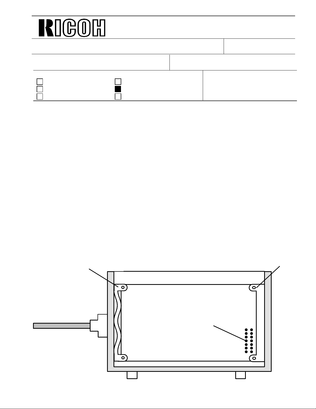
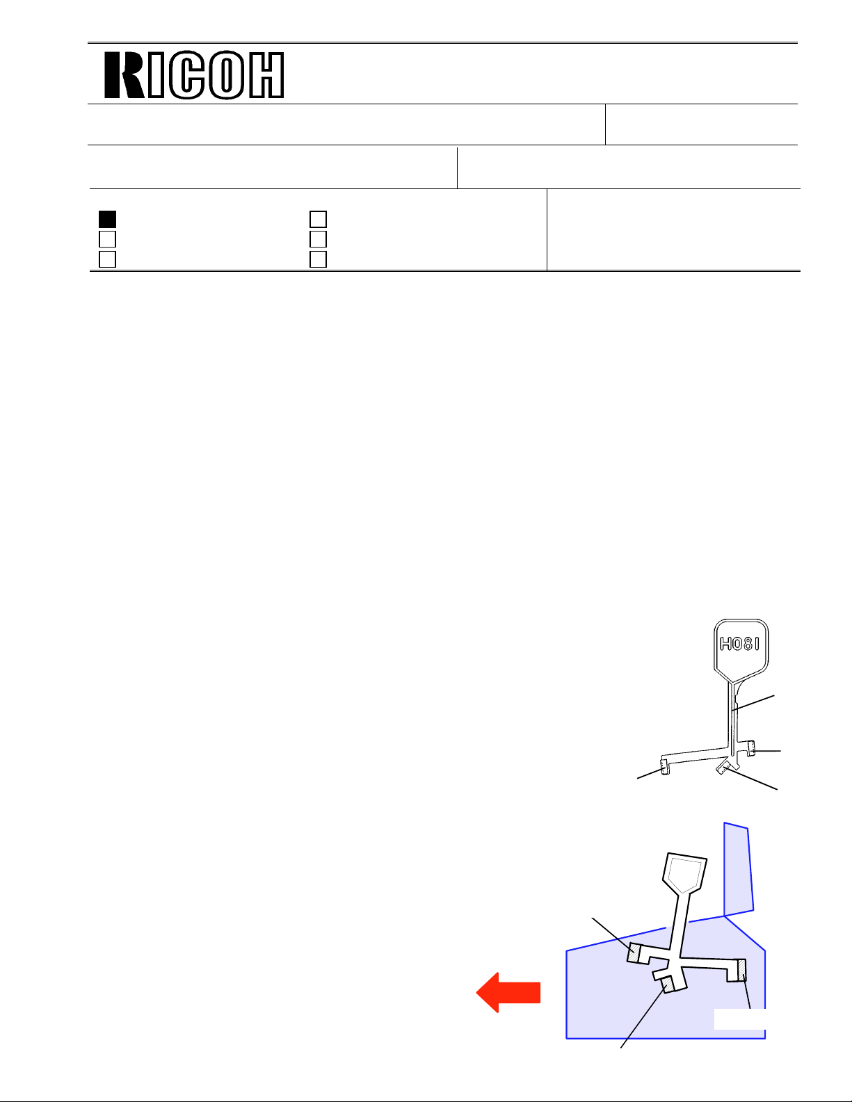
Bracket (A)
HDIF
Pins of CN2
Bracket (B)
Page 5
Technical Bulletin No. CFO-004
SUBJECT: NCU parameter setting for UK
PREPARED BY: N. Mihara
CHECKED BY:
CLASSIFICATION:
Action Required Revision of service manual
Troubleshooting Information only
Retrofit Information Other
When installing the above model in UK, change the NCU parpameter in accordance with the
PTT requirement as follows .
1. Make sure that the country codes for NCU parameter and bitswitch are for UK setting.
2. Change the RAM addresses as follows.
FROM: FAX T.S. Sec tion
MODEL: CFO
DATE:
Janualy 14th, 1993
(PTT requirement)
Address 0003B4 = 32(H) → 28(H )
Address 000399 = 43(H) → 42(H)
Address 0003B8 = 02(H) → 03(H )
The above correction will be applied into the software from the 1st productions of March ’93.
Page 6
Technical Bulletin No. CFO-006
SUBJECT: Installation of CFO 20M hard disk option in Sweden
DATE:
April 15th, 1993
PREPARED BY: N. Mihara
CHECKED BY:
CLASSIFICATION:
FROM: FAX T.S. Sec tion
MODEL: CFO
Action Required Revision of service manual
Troubleshooting Information only
Retrofit Information Other
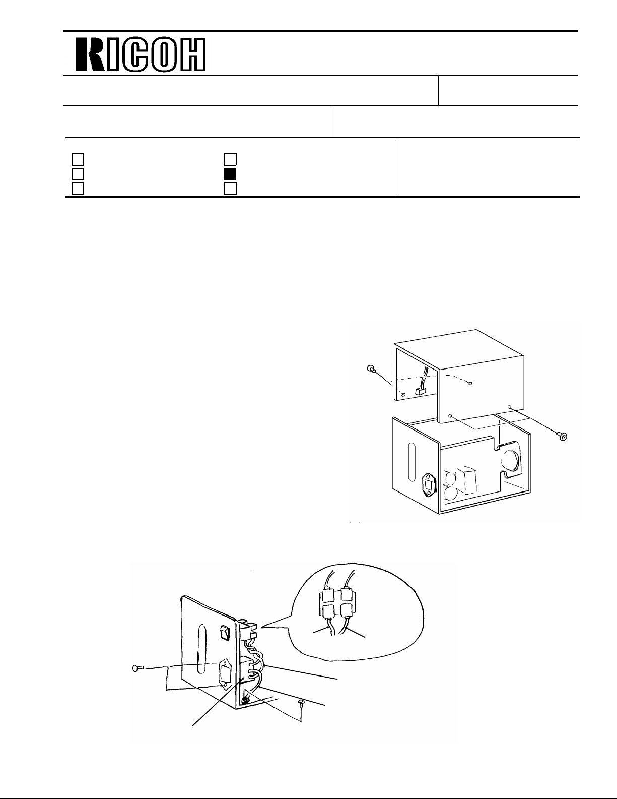
At installation in Sweden, the following parts have to be replaced to meet the Swedish safety
regulations.
* Replacement parts
1. Inlet filter (H044 8202B) x 1
2. Fuse (215 series 250V/ 2A) x 1
(These parts should be provided to REBV from Ricoh Tokyo, not thro u gh SPC.)
Procedure
1. Remove the hard disk cover (screw: M3 x 4)
2. Replace the inlet filter (Screw: M3 x 2, M4 x 1).
Brown
Wire
Inlet filter
AC SW
Blue wire
Twist the wires more
than th r ee ti mes.
Gree n/ ye llow wire
Page 7
Technical Bulletin No. CFO-006
SUBJECT: Installation of CFO 20M hard disk option in Sweden
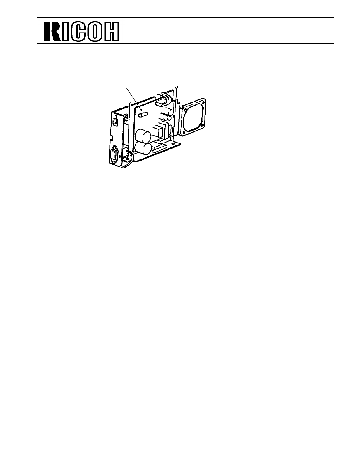
3. Replace the fuse on the PSU of the hard disk.
Fuse
4. Reassemble the hard disk unit.
DATE:
April 15th, 1993
Page 8
Technical Bulletin No. CFO-007
SUBJECT: Scratch on the OPU
PREPARED BY: N. Mihara
CHECKED BY:
CLASSIFICATION:
Action Required Revision of service manual
Troubleshooting Information only
Retrofit Information Other
FROM: FAX T.S. Sec tion
Problem
The OPU may be damaged when using the machine, as show n
below. However, there is no problem on the printed image.
Cause
1. Both sides of the development roller may touch the metal
blade on the development roller. By this, the shaved
corpuscles may get in the space between the OPU belt and
the development roller, the both sides of the OPU belt may be
damaged.
DATE:
April 15th, 1993
MODEL: CFO
Scratch
OPU guide
2. The position of the OPU guide may be changed for some
reason, then the OPU belt may touch the plastic pins on
the develpment unit.
Action
1. If the above problem occurs, do not replace the OPU, because, there will be no problem on
the printed image, in the lifetime of the OPU.
2. Do not adjust and change the position of the OPU guide.
Note
Do not touch the sorface of the OPU belt and not clean with alcohol.
Page 9
[2]
[1]
3rd mirror
Technical Bulletin No. CFO-008
SUBJECT: Dirty Mirrors
PREPARED BY: N. Mihara
CHECKED BY:
CLASSIFICATION:
Action Required Revision of service manual
Troubleshooting Information only
Retrofit Information Other
FROM: FAX T.S. Section
MODEL: CSO
DATE:
— Problem —
In the field, the scanner mirrors may become dusty (poor scanning quality).
In this case, we recommend that you do proced ures 1 and 2.
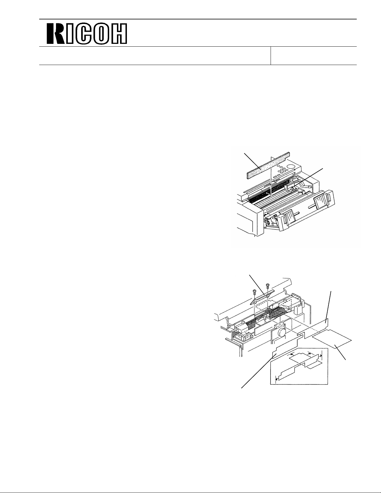
— Procedure —
Procedure 1.
Clean the mirrors with the mirror cleanin g kit.
It is easy to clean the mirrors (there is no need to remo ve th e ADF ba se).
June 30, 1993 .
P/N: H0819300 (for CSO) Mirror Cleaning Kit
• Mirror Cleaning Tool ×1pc
• Cleaning Felt ×30pcs
• Vinyl Bag ×1pc
[Preparation]
Attach the cleaning felts [1] to the mirror cleaning to ol [2]. (Fig. 1)
(With one set of felts, you can clean the mirror up to 10 times)
[Cleaning Method]
(1) Remove the exposure glass.
(2) Insert the cleaning tool into the scanne r. (Fig. 2)
(3) Clean the mirrors by sliding the tool.
(3~4 times for each mirror)
Front
Fig. 1
[1]
[1]
1st mirror
2nd mirror
Fig. 2
Page 10
Dust Protection
FCU
Technical Bulletin No. CFO-008
SUBJECT: Dirty Mirrors
Procedure 2.
Install the mirror protectio n she et kit. The sheets in the kit will prevent the mirrors fro m
becomeing dirty.
P/N: H0819900 Dust Prote ctio n Sh ee t Kit
• FCU Sheet × 1pc
• Dust Protection Sheet 1 × 1pc
• Dust Protection Sheet 2 × 1pc
• CTM Sheet × 1pc
[CTM Sheet Installation]
(1) Open the front cover, then cove r the OPC be lt with
a piece of paper (do not touch the belt surface by
hand).
(2) Attach the CTM sheet. (Fig. 3)
CTM Sheet
DATE:
June 30, 1993 .
Toner Duct
Fig. 3
[FCU Sheet Installation]
(1) Remove the rear/ left/ right/ lens covers.
(2) Insert the FCU sheet under the mirrors, then
attach the sheet to the right side and interior of
the ADF base. (Fig. 4)
[Dust Protection Sheet 1 and 2 Installation]
(1) Attach the dust protection sheet 1 to the left
side of the scann er and the upper side of the
shading plate. (Fig. 4)
(2) Attach the dust protection sheet 2 to the right
side of the scann er and the upper side of the
shading plate. (Fig. 4)
— Countermeasure —
Lens Cover
Dust Protection
Fig. 4
We have applied the modification (attaching the protection sheets to the productions) from the
June. productions.
Page 11

Technical Bulletin No. CFO-008
SUBJECT: Dirty Mirrors
CTM Sheet
DATE:
June 30, 1993 .
FCU Sheet
Dust Protection
Sheet
Page 12

Technical Bulletin No. CFO-009
SUBJECT: ADF Non Feed Problem
PREPARED BY: N. Mihara
CHECKED BY:
CLASSIFICATION:
Action Required Revision of service manual
Troubleshooting Information only
Retrofit Information Other
FROM: FAX T.S. Section
MODEL: CFO
DATE: July 27, 1993
[Problem]
Non feed at the ADF may occur if copie r pap er which has silicon e oil on the sorfa ce is u sed as
a original.
[Reason]
Some copier machines may leave too much silicone oil on copies.
[Countermeasure]
Please replace the pick-up roller with the following countermeasure part.
Part No. H081950 4: Pick up roller (Carbor undum roller)
Note: Please note that th e ADF capacity will be decreased.
if the carborundum roller is installed.
ADF capacity: 50 sheets (Normal rubber roller)
20 sheets (Carborundum roller)
Page 13

Technical Bulletin No. CFO-010
SUBJECT: Rx Error (with ISDN G3)
PREPARED BY: N. Mihara
CHECKED BY:
CLASSIFICATION:
Action Required Revision of service manual
Troubleshooting Information only
Retrofit Information Other
FROM: FAX T.S. Section
[Problem]
During ISDN G3 reception, communication failure may occu r.
[Cause]
Codec gain (ISDN) for the rx signal is too much hig h.
[Action]
DATE: Aug 16th, 1993
MODEL: CFO
Please reduce the codec gain from -0. 5d B to -4.5 dB using RAM address 00015A(H) as follows.
Address 00015A(H)
BIT NO Description
Codec Gain
0
1
2
0
0: -4.5
0 dB
1
0: -2.5
B dB
0
1: -0.5
0 dB
1
1: +1.5
0 dB
0
0: +3.5
1: dB
1
0: +5.5
1 dB
0
1: +7.5
1 dB
1
1: +9.5
1 dB
[Countermeasure]
We have modified the soft ware from th e April ’93 pro du ctio n run (MB CFO-03 2).
Page 14

Technical Bulletin No. CFO-011
SUBJECT: Spare Parts List for CFO options
PREPARED BY: H.Yokoyama
CHECKED BY:
FROM: 2nd T.S. Section
CLASSIFICATION:
Action Required Revision of service manual
Troubleshooting Information only
Retrofit Information Other
We issue the parts list for the CFOs optional ISDN and HD kits.
<ISDN>
- For 115V areas -
P/N Description Q’ty
H082 6017 PCB-CIG4: USA 1
H143 4002 Bracket - CIG4 1
H143 4010 Cover - CIG4 Connector 1
- For 200V areas -
• For the machines with model codes H082-40,51,52,83,90.
P/N Description Q’ty
H082 6016 PCB - CIG4: E/A 1
H143 4002 Bracket - CIG4 1
H143 4010 Cover - CIG4 Connecor 1
• For the machine with model code H082-30.
DATE:
Feb. 21st, 1994
MODEL: CFO all model
P/N Description Q’ty
H082 6016 PCB - CIG4: E/A 1
H143 4002 Bracket - CIG4 1
H143 4001 Cover - CIG4 Connector: H 1
<HD Kit>
- For 115V areas -
P/N Description Q’ty
H082 6011 PCB - OPIF 1
H082 6024 PCB - HDCB 1
H044 8250 PSU Ass’y: US 1
H044 6021 PCB - HDIF 1
H044 8251 HD Unit 1
- For 200V areas -
P/N Description Q’ty
H082 6011 PCB - OPIF 1
H082 6024 PCB - HD CB 1
H043 8250 PSU Ass’y: E/A 1
H044 6021 PCB - HDIF 1
H044 8251 HD Unit 1
Page 15

Technical Bulletin No. CFO-012
SUBJECT: CFO(F) may not detect IT2.
DATE:
June,3rd, 19 94
PREPARED BY: H.Yokoyama
CHECKED BY: S.Hamano
CLASSIFICATION:
Action Required Revision of service manual
FROM: 2nd T.S. Section
MODEL:
CFO(F)
Troubleshooting Information only
Retrofit Information Other
<Problem>
CFO(French version) does not detect IT2 when is connected to a PABX.
<Couse>
The level of IT2 after th e PABX exchanger does not mat ch the French PTT standards.
<Modification>
The range for the parame ter for detecting IT2 has been made wid er th an previo us setting.
The following are the part number cha ng es fo r the modif ication.
• H0826038C → D PCB-MBU : F
(H0827161C → D) Programmed ROM : F
• H0826043A → B PCB-FCU : F
(H0827163A → B) Programmed ROM : F
This will affect machines from April p rod uct ion, 1994.
<Action>
If you have this problem, rep lace the above pa rts (pro gra mmed ROMs) at the same time and do
the following.
(1) Set the valve of NCU parameter No.00 to "00H" (This means set the country code to
"France" )
(2) Press "Yes"
Then the machine sets th e pa rameter automatically.
Page 16

Technical Bulletin No.CFO-013
SUBJECT: Service Manual Correction
PREPARED BY: H.Yokoyama
CHECKED BY: S.Hamano
CLASSIFICATION:
Action Required Revision of service manual
Troubleshooting Information only
Retrofit Information Other
The following are corrections for the CFO service manu al.
1. Section 4.2 BIT SWITCHES
Factory Setting for the bit switches
Bit Switch No. Wrong Correct
1E 00100001 00110001
2. Section 4.3 NCU PARAMETERS
Factory settings for the NCU parameters
FROM: 2nd T.S. Section
DATE:
June,10th , 1994
MODEL:
CFO (Siemens)
NCU Parameter
No.
04 Not described FF(H)
05 Not described 00(H)
09 HIGH
10 LOW
19 -14dB -7dB
3. Section 4.1.14 RAM Tests (Function 13)
Please add the following note to the start of section 4.1.14 as shown on the att ach ed shee t.
<Note>
It is not recommended to try the S-RAM check at a customer site.
In S-RAM check mode, the software may hang up if the fax machine’s prog ram tries to
access an address that is currently being checked. If this occurrs, the machine will
continue to indicate "NOW CHECKING", and will have to be switched off . Swit chin g th e
power off will cause a total reset of the stored RAM data.
Wrong Correct
LOW
90(H)
HIGH
01(H)
Page 17

3. Press a key from 0 to 5, depending on the required pattern. Use ↑ and ↓ to see what patterns are available.
4. Start
A test pattern is printed.
5. To finish: Yes x 2
4.1.14. RAM Tests (Function 13)
Note: It is not recommended to try the S-RAM che ck at a cust ome r site.
In S-RAM check mode, the softwa re may ha ng up if th e fa x machine’s program tries to acce ss an
address that is currently being checke d. If this occurrs, the machine will cont inu e to indica te
"NOW CHECKING", and will have to be switched off . Swit ching the power off will cause a total reset of the stored RAM data.
1. After entering service mode,
press 1 3
RAM TEST NO. _
0 SRAM 1 SAF
2 PAGE MEMORY
2. Either:
• Test the SRAM: 0 Start
• Test the SAF: 1 Start
• Test the page memory: 2 Start
If there is a problem, a display of the following type will occur.
SAF
PRESS START
ADDRESS=300002 W=55 R=00
Keep a note of the informat ion on the display, the n pre ss Start to resume testing.
3. When the test has finished, "OK" is disp laye d. Press Yes to finish.
4.1.15. Service Station Telephone Number (Function 14)
1. After entering service mode,
press 1 4
S.S.NO ENTER FAX NUMBER
NO
TO CANCEL
2. Input the telephone number of the service station that will re ceive Au to Service calls from this
machine.
Then press Yes .
If the ISDN Option kit has been insta lled, press the Line Selector key t o select either G3 or G4
before inputting the number.
Page 18

Technical Bulletin No. CFO-014
Page 1/4
SUBJECT: CE Mark
PREPARED BY: K. Ugaeri
CHECKED BY: M. Iwasa
CLASSIFICATION:
Action Required Revision of service manual
Troubleshooting Information only
Retrofit Information Other
To meet new EMC standards for the CE Mark, some ele ctric pa rts have be en modif ied since
August ’95 production.
A. CFO
1. PSU-C20-EUR. (H0825502E)
The shape of the heat sink has be en modified in order to add the Sh ield Plate of the PSU.
FROM: 2nd T.S. Section
MODEL:
DATE:
Oct. 15, 1995
CFO (Europe Version)
G4 Kit (Europe Version)
PSU
* The new Shield Plate is not registe red as a service part.
2. PCB-FCU (H0826042H)
PCB-FCU (H0826043D for France)
The SBT Coil (SBT-0410) which is connected to pin 12 of IC27 has been changed to Filter
(ELKTH150GA).
IC27
Page 19

Technical Bulletin No. CFO-014
Page 2/4
SUBJECT: CE Mark
3. Power Pack (H0815020B)
C101 has been changed from 22µF to 100µF, 35V.
4. Harness - FCU 24V (H0825123)
Harness - Paper Size Sensor (H08251 24)
A magnet cor e ha s b een added on both harnesse s.
DATE:
Oct. 15, 1995
5. Covers of LDUNI
Ground Wire of the LDUNI Cover
For LD-UNIT, the covers and ground wire have been added.
* New covers, shielding plates, and the ground wire are not registered as service parts.
Page 20

Technical Bulletin No. CFO-014
Page 3/4
SUBJECT: CE Mark
B. G4 Kit
1. PCB-CIG4-EU2 (H0826016G)
(1) Fil1 has been removed and a con de nser (0.1 µF) has been added at JP4.
(2) R62 has been changed from 56 Ω to 200Ω.
(3) A condenser (100pF) has been added between R62 and COM1.
(4) R49 has been changed from 100 Ω to an Inductor.
(1)
DATE:
Oct. 15, 1995
IC 6
(2), (3)
(4)
IC 6
Page 21

Technical Bulletin No. CFO-014
Page 4/4
SUBJECT: CE Mark
2. ISDN Cable (H0825700)
• A filter (magnet core) has been added on the ISDN Cable.
DATE:
Oct. 15, 1995
3. Ground Wire (H0825125)
• Two ground wires have been ad de d between the C1G4 Cord and th e Bra cket.
Page 22

Page 1/1
Kmxml
Technical Bulletin
SUBJECT: Black bands/lines on the received copy
L~
Mihara
FROM: FAXT.S. Section
❑
Revision of service manual
❑
Information only
❑
Other
PREPARED BY: N.
CHECKED BY:
CLASSIFICATION:
❑
Action Required
■
Troubleshooting
❑
Retrofit Information
Problem
On receive copies, black bands or lines may be
printed, especially on the right side.
Cause
No.
CFO-005
DATE:
February. 16th, 1993
MODEL: CFO
!
I
Toner or dust is attached on the charge corona wire.
Countermeasure
Clean the charge corona wire and the grid plate.
t
/
I
Action
1.
At PM or EM,
plate,
If you replace
If you receive
2.
sliding the cleaner 2-3 times periodically.
Do not change the charge corona voltage from the power pack with the VR, otherwise, the
3.
life time of the OPC may be decreased.
clean the charge corona wire (by sliding the cleaner 2-3 times) and the grid
the charge corona wire, please replace it as a eraser
a complaint, please advise the customer to clean the charge corona wire by
ass’y.
Page 23

Page 1/2
Technical Bulletin No. GENERAL-004
SUBJECT: Black bands/lines on the received copy
PREPARED BY: H.Yokoyama
CHECKED BY:
CLASSIFICATION:
Action Required Revision of service manual
Troubleshooting Information only
Retrofit Information Other
FROM: 2nd T.S. Section
MODEL: USA only
CSO, CFO, CS1/CRO
DATE:
November 11th, 1993
[Problem]
On the received copies, bla ck ban ds or line s may
be printed, especially on the right hand side.
[Cause]
Toner or dust is attached to the charge corona wire.
[Modification]
The electric current of the charge coron a will be
increased to avoid applying uneren charg to the
master which is caused by a dirty corona wire.
Because of the increase of the ele ctric curre nt , th e
distance betwee n th e grid plate and the coro na
wire will be changed to keep the charge on the
master belt the same as before modification.
• H081 2870 → H081 2854 Eraser Ass’y
• H081 5030 → H081 5020 Power pack (CSO/CFO)
H510 5030 → H510 5020 Power pack (CRO/CS1)
<Eraser Ass’y>
• The thickness of the cleaning blad e of the cle an er will be cha ng ed to incre ase the
cleaning ability (4mm → 5mm)
• The distance between the gride plate and charg e wire will be cha nged (6mm → 8mm)
<Power pack>
• The range and initial value of the VRC (VR for the charge coro na ) will be changed.
The above modification will ta ke pla ce fro m t he De cemb er 1st prod uction.
Page 24

Page 2/2
Technical Bulletin No. GENERAL-004
SUBJECT: Black bands/lines on the received copy
DATE:
November 11th, 1993
[Countermeasure in the field]
The countermeasu re method depends on the CV (Copy V olu me) of the machine.
• If the CV is less than 400 sheets/month
Turn VRC on the power pack to the maximum (Turn the VR clockwise until it stops)
• If the CV is more than 400 sheet s/mo nth
Change the Eraser to the modified one and turn VRC on the power pack to the maximum.
Note:The increase in the powe r of VRC may de crease the life time of the maste r u nit , so for
customers whose ACV/month is more than 400 sheets, the Erase r shou ld be chan ged.
[Request]
The essence of this problem is a dirty cha rge corona wire, so please do the following
• When a sales or service person visits a customer (at PM or EM), clea n th e charge
corona wire with the built-in cleaner
• Advise the customer to clean the charge corona wire at a certain int erval or if the
customer sees black bands/lines on the received copy.
Page 25

Page 1/2
Technical Bulletin No. GENERAL-005
SUBJECT: Black bands/lines on the received copy
PREPARED BY: H.Yokoyama
CHECKED BY:
CLASSIFICATION:
Action Required Revision of service manual
Troubleshooting Information only
Retrofit Information Other
FROM: 2nd T.S. Section
MODEL: Europe, Asia
CSO, CFO, CRO
DATE:
Feb. 3rd, 1994
[Problem]
On the received copies, bla ck ban ds or line s may
be printed, especially on the right hand side.
[Cause]
Toner or dust is attached to the charge corona wire.
[Modification]
The electric current of the charge coron a will be
increased to avoid applying uneren charg to the
master which is caused by a dirty corona wire.
Because of the increase of the ele ctric curre nt , th e
distance betwee n th e grid plate and the coro na
wire will be changed to keep the charge on the
master belt the same as before modification.
• H081 2870 → H081 2854 Eraser Ass’y
• H081 5030 → H081 5020 Power pack (CSO/CFO)
H510 5050 → H510 5051 Power pack (CRO)
<Eraser Ass’y>
• The thickness of the cleaning blad e of the cle an er will be cha ng ed to incre ase the
cleaning ability (4mm → 5mm)
• The distance between the gride plate and charg e wire will be cha nged (6mm → 8mm)
<Power pack>
• The range and initial value of the VRC (VR for the charge coro na ) will be changed.
The above modification will take pla ce fro m t he Feb. 1st pro du ctio n.
Page 26

Page 2/2
Technical Bulletin No. GENERAL-005
SUBJECT: Black bands/lines on the received copy
DATE:
Feb. 3rd, 1994
[Countermeasure in the field]
The countermeasu re method depends on the CV (Copy V olu me) of the machine.
• If the CV is less than 400 sheets/month
Turn VRC on the power pack to the maximum (Turn the VR clockwise until it stops)
• If the CV is more than 400 sheet s/mo nth
Change the Eraser to the modified one and turn VRC on the power pack to the maximum.
Note:The increase in the powe r of VRC may de crease the life time of the maste r u nit , so for
customers whose ACV/month is more than 400 sheets, the Erase r shou ld be chan ged.
[Request]
The essence of this problem is a dirty cha rge corona wire, so please do the following
• When a sales or service person visits a customer (at PM or EM), clea n th e charge
corona wire with the built-in cleaner
• Advise the customer to clean the charge corona wire at a certain int erval or if the
customer sees black bands/lines on the received copy.
Page 27

Magnet
Page 1/1
Technical Bulletin No. GENERAL-006
SUBJECT: CTM modification
DATE:
April, 11th, 1994
PREPARED BY: H.Yokoyama
CHECKED BY:
CLASSIFICATION:
Action Required Revision of service manual
FROM: 2nd T.S. Section
MODEL:
CSO, CFO, CS1
Troubleshooting Information only
Retrofit Information Other
To avoid toner from being spilt inside the machin e, the toner collection roller of th e CTM will be
modified.
<Figure>
Previous
Type A Type B
Brush 4 Magnets Magnet surface
After modification
Magnet
Black lot no. is printed on the
carton box.
<Expected arrival period>
Previous Type
Type A
Type B
’94.1
Red lot no. will be printed on
the carton box.
’94.6
’94.8
’94.6
Blank lot no. will be printed
on the carton box.
Page 28

Page 1/1
Technical Bulletin No. GENERAL-008
SUBJECT: Replacing the toner cassette
PREPARED BY:H. Yokoyama
CHECKED BY:
CLASSIFICATION:
Action Required Revision of service manual
Troubleshooting Information only
Retrofit Information Other
The instruction of the operator’s manual for replacing the toner cassette (CTM) is wrong.
We will insert the errata sheet to the operator’s manual.
Wrong: 1. Switch off the machine.
Correct: Keep the power switch on when replacing the toner cassette.
FROM: 2nd T.S. Section
MODEL:
CSO, CFO, CRO, CS1
DATE:
April, 11th, 1994
Page 29

Page 1/1
Technical Bulletin No. GENERAL-009
SUBJECT: Vertical Black Lines
PREPARED BY: H.Yokoyama
CHECKED BY: S.Hamano
CLASSIFICATION:
Action Required Revision of service manual
Troubleshooting Information only
Retrofit Information Other
[Problem]
Vertical black lines appear on the printed image.
[Cause]
The toner may stick on the Hot Roller, Fusing Stripper, Thermistor, an d The rmost at and this
toner may damage the surf ace of th e Hot Roller. Then, during copyin g toner is transferred by
the scratched part of the roller to cause vertical bla ck lines on the print ed image .
FROM: 2nd T.S. Section
MODEL:
CSO, CFO, CRO, CS1
DATE:
Jury. 30, 1994
[Countermeasu re]
The material of the surface of the Hot Roller ha s bee n cha nged to pre ven t th e tone r from
sticking on the Roller by the following modification
H0812100D → E
Because of the ab ove mo dif ication, the vende r has be en changed.
[Effective S/N]
H081-24, 40, 46, 51, 54 , 59 , 60: Oct., 199 3 ~
H510-20: R88310006 09 ~
21, 22, 27, 30, 40, 51, 59, 60: Nov., 1993 ~
H082-20, 23, 30, 40, 51 , 59 , 60 : Nov. , 19 93 ~
H511-20, 21, 22, 27: Nov. , 19 93 ~
[Action]
Clean the Fusing Stripper, The rmisto r and Thermo stat and take out the toner f rom th em whe n
visit the customer.
Page 30
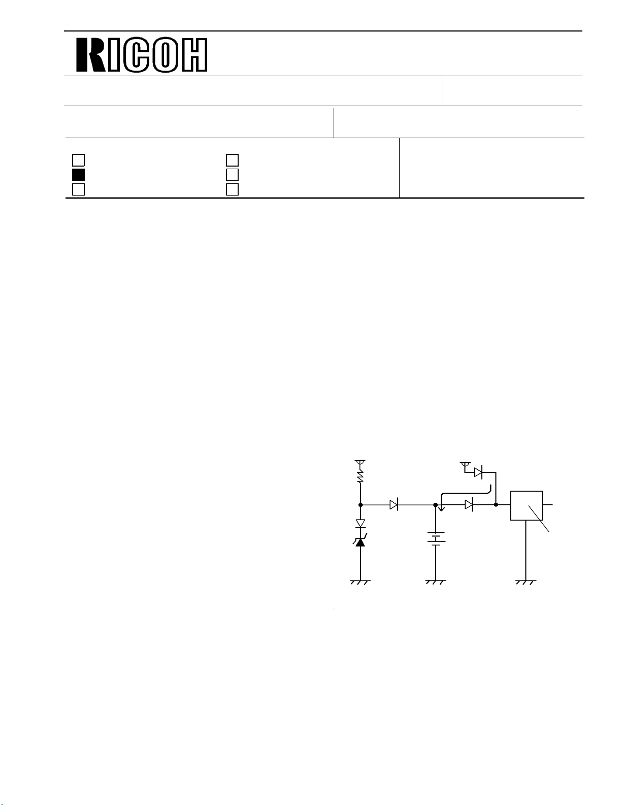
Leak Current
(On CFO / CS1 FCU)
Diode
COM
COM
Regulator
Technical Bulletin No. Multi-001
SUBJECT: Memory Back-up Battery
DATE:
Jan. 19, 1995
PREPARED BY: Y.Okunishi
CHECKED BY: S.Hamano
CLASSIFICATION:
Action Required Revision of service manual
FROM: 2nd T.S. Section
MODEL:
CSO, CFO, CS1, LHO
Troubleshooting Information only
Retrofit Information Other
[Symptom]
Stored documents in the me mory migh t be erase d when the main power goes down .
A power failure report is printed with the following informa tion.
• Memory Tx Files: Destination names or fax numbers are print ed .
• Substitute Recept ion File s: The Sende r’s RTI or CS I is print ed if the y are pro gra mmed.
CSO rejects incoming messages without RTI or CSI because
of the factory setting.
• Memory Lock Files: Programmed Quick Numbers are printed.
[Cause]
Power loss from the memory back-up battery on FCU caused by excessive charge current, for
the following reasons.
(1) Leak current from Diode
The battery is charged afte r it is alread y
24V
24V
fully charged. This type of battery
is damaged if this occurs.
(2) Excessive charge voltage (CFO,
CS1,LHO) The target charge voltage
was 6.2V against 6. 4V or und er which is
recommended by the battery maker.
This margin was too small for this battery.
Zener
Diode
Battery
COM
[Modification]
See MB C Series-048A.
OUT
Page 31

Technical Bulletin No. Multi-001
SUBJECT: Memory Back-up Battery
[Action Taken]
1. Install the modified FCU to deal with customer claims.
2. Request technicians not to turn off the main po wer if a do cume nt is stored
in the memory.
[Note]
• Stored data other than docume nts is not erased even if the main power goes do wn.
DATE:
Jan. 19, 1995
Page 32

Technical Bulletin No. Multi-002
SUBJECT: Toner Spillage during Transportation
PREPARED BY: Y. Okunishi
CHECKED BY: M. Iwasa
CLASSIFICATION:
Action Required Revision of service manual
Troubleshooting Information only
Retrofit Information Preventive Action
Background: Machines have been sent to customers afte r p re-in stallation and sent back to the
service center for repair.
Problem: Toner had spread inside the machin e du ring transportation.
Cause: Toner leaked from the development unit, the toner cartridge, or somewhe re
in the toner path during tran sportation.
Preparation for transportation:
(1) Transportation withou t he avy vibra tio n
(Example: A technician should carry the machine with care.)
• F/L series fax machines:
The development unit can be connected to a CTM with toner.
However, the toner path under the CTM must be covered by some
adhesive tape. See the attached illust rat ion.
• C series fax machines:
Follow RTB No. CSO-006
• Other order machines:
Follow (2) below.
FROM: 2nd T.S. Section
MODEL:
All laser plain paper fax
machines
DATE:
Jul. 15.1995
(2) Transportation with heavy vibration
(If a third party handles the transportation, follow this procedure.)
• F/L series fax machines:
Remove the development unit and the CTM fro m the machin e if toner
has been installed. They must not be delivered in the same box as the
machine, because they contain toner which may spill out. Th e to ne r
inside the machine must be clean ed away or th e toner path under the
CTM must be covered with tape.
• C series fax machines and others:
Remove the development unit and CTM (or Toner Cartridge) from
the machine if toner has been inst alle d, and clean the toner from
inside the machine.
The removed development unit and CTM must not be delivered
in the same box as the machine.
Page 33

Technical Bulletin No. Multi-002
SUBJECT: Toner Spillage during Transportation
Inside of FX6 and LSO
Drum
DATE:
Jul. 15.1995
Toner path
Note: Adhesion of the tap e sho uld not be strong. Otherwise, it ma y not be ta ken off
cleanly from the machine, or th e toner path may be damaged whe n it is taken
off.
Please request tape samples for th e FX6 and LSO from Ricoh.
Adhesive tape
Page 34

Page 1/3
Technical Bulletin No. Multi - 004A
SUBJECT: Fusing Unit
PREPARED BY: Y.Okunishi
CHECKED BY: S.Fujii
CLASSIFICATION:
Action Required Revision of service manual
Troubleshooting Information only
Retrofit Information Other
A: "NOTE" is added to page 2/3.
SYMPTOM:
Background on received and copied documents.
Cause:
Hot Roller failure as a result of not changing the Cleaning Pad at the 10K PM.
Failure to change the Cleaning Pad results in dirty Strippers and Thermostat and
then Hot Roller failure.
As the machine warms up from the standby temperature to the fusing
temperature, it is exposed to slight overheating before the temperature levels
off. This leads to softening of the Teflon layer on the Hot Roller. As a result, the
Teflon layer peels off in the areas where the Strippers and other parts come in
contact with it. Dirty Strippers and Thermostat put more stress on the Hot Roller and
cause premature Hot Roller failure.
Also, the dirty Thermistor causes the Hot Roller to overherat and fail prematurely.
FROM: Quality Assurance Center
DATE:
Oct. 15, 1996
MODEL:
CSO, CRO, CS1, CFO,
CGO
A second cause can be a damaged (bent ) Thermistor from a previous service visit.
The damaged Thermistor causes the Hot Roller to overheat and fail prematurely.
SOLUTION:
Ricoh recommends replacing the Cleaning Pad at the 10K PM. However, this is
sometimes ignored. Realizing this, Ricoh will conduct the following modifications to
protect the Hot Roller from the failure mentioned above.
No. Old Part New Part Description Qty Used Interchangeability
1 H0812121 H0812123 Stripper Spring 2 → 2 X / O
H0812120 H5132119 Stripper
2
3
H0812137
H0815035
H0812141
03130080B
(Separation Pawl)
Thermistor Assembly
Thermistor
Bracket
Screw - M3x8
2 → 2 X / O
1 → 0
1 → 1
1 → 1
0 → 1
X / O as an
assembly
4 H0812100 H0819600 Hot Roller Kit 1 → 1 X / O
Page 35

Page 2/3
Technical Bulletin No. Multi - 004A
SUBJECT: Fusing Unit
DATE:
Oct. 15, 1996
Hot Roller Kit:
The hot rollers shipped from the SPC in Japan will be replaced by the
Hot Roller Kit in July.
This kit will be comprised of the following: Hot Roller, Cleaning Pad, Thermistor,
Thermistor Bracket, Screw, Strippers (2), Stripper Springs (2) and Installation Sheet.
The individual Hot Roller will be no longer available. The Cleaning Pad will
continue to be a Service Part.
Ricoh recommends change of the above modified parts and Cleaning Pad when the failed
Hot Roller is replaced with the new one.
NOTE
(A): Please refer to the following instructions and fix the cover to the fusing unit
and check that the harness is not pinched before installing the fusing unit in the
machine.
If the metal wire of the harness contacts the thermistor bracket, a no power
condition may occur. Please check the thermistor harness if this occurs.
Fusing Cover
(Bad)
Edge of the cover may damage
the harness
Edge
(Good)
Fusing Unit
Page 36

Installation Procedure for the Thermistor
1. Assemble the thermistor and the bracket
with the screw.
Bracket - Thermistor
H0812141
Thermistor - Fusing Unit
H0815035
Do not bendthis part
2. Install the
Thermistor Ass’y
( ✻ 4)
Thermistor - Fusing Unit
H0815035
Harness - Thermostat
(✻ 3)
Page 3/3
Thermostat - Fusing Unit
H0812134
Screw - M3 x 8
03130080B
(✻ 1)
Note: Set the projection on
the thermistor into
the hole in the bracket.
Note: ✻ 1 Place the thermostat harness under the part of the bracket.
✻ 2 Do not cross the thermostat harness and the thermistor harness.
✻ 3 Push the thermistor head (sensor) gently against the hot roller witha finger to make sure that the thermistor
head touches the hot roller surface. Do not push it strongly.
✻ 4 Do not bend the thermistor neck (spring plate) when installing or cleaning it .
If the thermistor is bent, replace it.
(✻ 2)
Bracket - Thermistor
H0812141
Stay - Fusing Unit - Upper
H0812175
Page 37

T
Model:
K105 (FAX4000L)
echnical
B
ulletin
Date:
15-Sep-97
No:
PAGE: 1/1
015
Subject:
From:
Classification:
The V.33 standard for 14.4 kbps modems has not been supported by FX4 and FX6MK2
because V.33 has been deleted from the ITU (CCITT) recommendations.
So, data transfer at 14.4 kbps speed between a FAX4000L which supports only V.33 and
products which support only V.17 will not be successful, and 9.6 kbps is the highest speed
for data transfer between them .
See the following list.
Only V.33 is supported V.33 and V.17 are
14.4 Kbps Modem
QAC 2nd Field Information Dept.
Troubleshooting
Mechanical
Paper path
Other ( )
K105 (FAX4000L) CFO, CS1, CGO FX6MK2, FX4
Part information
Electrical
Transmit/receive
supported
Prepared by:
Action required
Service manual revision
Retrofit information
Only V.17 is supported
Y.Okunishi
RC RE ASIA
✶✶
Page 38

T
Model:
ISDN Option
echnical
ulletin
B
Date:
30-Nov-97
No:
PAGE: 1/1
Multi - 006
Subject:
From:
Classification:
This technical bulletin informs of the settings required when a machine is connected to the
US National ISDN network
Models: CFO, CGO, LHO, FX4, ADAM
• Subscriber Number
Input the subscriber number given by the telephone company at :
1.G4 SUBSCRIBER NO.1 (MAIN)
2.G3 SUBSCRIBER NO.1 (MAIN)
• SPID Number (Service Profile Identification Number)
Input the SPID number given by the telephone company at :
US National ISDN
IPP Business Division Technical Service Dpt.
Troubleshooting
Mechanical
Paper path
Other ( )
Part information
Electrical
Transmit/receive
Prepared by:
Action required
Service manual revision
Retrofit information
H.Kamiya
1.G4 SUBSCRIBER NO.2 (Sub)
2.G3 SUBSCRIBER NO.2 (Sub)
Note: Input a ”_” (pause) before the SPID number.
• G4 Internal Switches
SW No. Bit Setting Definition
SW11 Bit1 0: Dynamic TEI Type of TEI used (Layer 2) (Default)
Bit2 1: Yes Attachment of calling p arty number (L3 SET UP)SW13
Bit5 1: Yes Attachment of channel information element (L3
CONN)
Bit0 1: Speech ISDN G3 information transfer capability (L3)SW14
Bit5 1: Keypad facility Called ID mapping (L 3)
SW15 Bit7 1: On Transmission of STAT in reply to STAT_ENQ
received in the U0 state.
SW19
Bit0 1: Permanent Permanence of the link (L2)
Bit2 1: On SPID procedure (L2)
Note: After completing a G4 service mode operation, turn off the machine and turn it
back on to make the new settings take effect.
RC RE ASIA
∗
Bit3 1: On G4 SPID procedure (L2)
 Loading...