

Page 1

RICOH FAX 4500L
SERVICE M ANUAL
Page 2
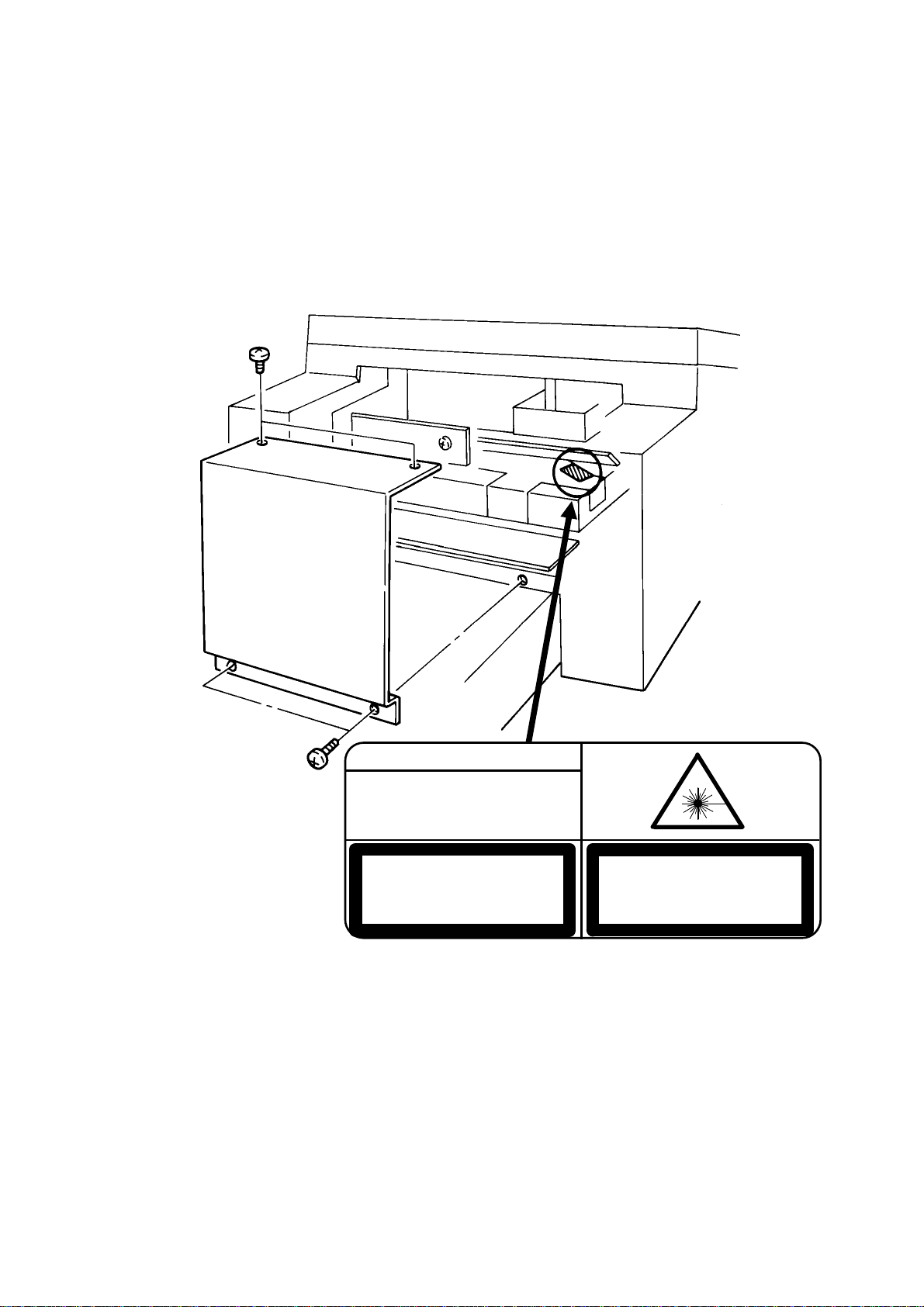
DANGER
INVISIBLE LASER RADIATION
WHEN OPEN AVOID DIRECT
EXPOSURE TO BEAM
CAUTION
LASER RADIATION WHEN
OPEN AVOID EXPOSURE
TO BEAM
VORSICHT
UNSICHTBARE LASERSTRAHLUNG,
WENN ABDECKNG GEOFFNET
NICHT DEM STRAHL AUSSETZEN
Page 3

CONTENTS
1. OVERALL MACHINE INFORMATION
1.1. SPECIFICATIONS . . . . . . . . . . . . . . . . . . 1-1
1.2. FEATURES . . . . . . . . . . . . . . . . . . . . . 1-2
1.3. COMPONENT LAYOUT . . . . . . . . . . . . . . . . 1-5
1.3.1. Mechanical Components . . . . . . . . . . . . . . 1-5
1.3.2. Drive Components . . . . . . . . . . . . . . . . . 1-7
1.3.3. Electrical Components . . . . . . . . . . . . . . . 1-9
1.4. OVERALL MACHINE CONTROL . . . . . . . . . . . . . 1-13
1.5. VIDEO DATA PATH . . . . . . . . . . . . . . . . . . 1-14
1.5.1. Transmission . . . . . . . . . . . . . . . . . . . 1-14
1.5.2. Reception . . . . . . . . . . . . . . . . . . . . 1-14
1.6. POWER DISTRIBUTION . . . . . . . . . . . . . . . . 1-15
1.6.1. Distribution Diagram . . . . . . . . . . . . . . . . 1-15
1.6.2. Memory Back-up Circuit . . . . . . . . . . . . . . . 1-16
2. DETAILED SECTION DESCRIPTIONS
2.1. SCANNER . . . . . . . . . . . . . . . . . . . . . . 2-1
2.1.1. Mechanisms . . . . . . . . . . . . . . . . . . . 2-1
1. Document Detection . . . . . . . . . . . . . . . . . 2-1
2. Pick-up and Feed . . . . . . . . . . . . . . . . . . 2-2
3. Manual Feed . . . . . . . . . . . . . . . . . . . 2-3
2.1.2. Video Data Processing . . . . . . . . . . . . . . . 2-4
2.2. PRINTER . . . . . . . . . . . . . . . . . . . . . . 2-5
2.2.1. Mechanisms . . . . . . . . . . . . . . . . . . . 2-5
1. Master Unit . . . . . . . . . . . . . . . . . . . . 2-5
2. Charge Corona Unit . . . . . . . . . . . . . . . . . 2-6
3. Laser Optics . . . . . . . . . . . . . . . . . . . . 2-7
4. Development . . . . . . . . . . . . . . . . . . . 2-8
5. Paper Feed . . . . . . . . . . . . . . . . . . . . 2-12
6. Transfer Corona Unit . . . . . . . . . . . . . . . . 2-21
7. Fusing Unit . . . . . . . . . . . . . . . . . . . . 2-22
8. Cleaning . . . . . . . . . . . . . . . . . . . . . 2-23
9. Quenching . . . . . . . . . . . . . . . . . . . . 2-24
Page 4

2.2.2. Circuits . . . . . . . . . . . . . . . . . . . . . 2-25
1. Laser Diode . . . . . . . . . . . . . . . . . . . . 2-25
2. Fusing Unit . . . . . . . . . . . . . . . . . . . . 2-27
2.3. PCBs AND THEIR FUNCTIONS . . . . . . . . . . . . . 2-29
2.3.1. FCU . . . . . . . . . . . . . . . . . . . . . . 2-29
2.3.2. MBU . . . . . . . . . . . . . . . . . . . . . . 2-31
2.3.3. SBU . . . . . . . . . . . . . . . . . . . . . . 2-32
2.3.4. OPU . . . . . . . . . . . . . . . . . . . . . . 2-32
2.3.5. LDDR . . . . . . . . . . . . . . . . . . . . . . 2-33
2.3.6. PFU . . . . . . . . . . . . . . . . . . . . . . 2-33
2.3.7. NCU . . . . . . . . . . . . . . . . . . . . . . 2-34
2.3.8. PSU . . . . . . . . . . . . . . . . . . . . . . 2-35
3. INSTALLATION
3.1. CONNECTING UP THE MACHINE . . . . . . . . . . . . 3-1
3.2. INSTALLING ADDITIONAL UNITS . . . . . . . . . . . . 3-2
3.2.1. Lower Cassette . . . . . . . . . . . . . . . . . . 3-2
3.2.2. Memory Card . . . . . . . . . . . . . . . . . . . 3-6
3.2.3. Cassette (250 Sheets) . . . . . . . . . . . . . . . 3-7
3.2.4. Cassette (500 Sheets) . . . . . . . . . . . . . . . 3-8
3.2.5. Handset . . . . . . . . . . . . . . . . . . . . . 3-9
3.2.6. Hard Disk . . . . . . . . . . . . . . . . . . . . 3-10
3.3. INITIAL PROGRAMMING . . . . . . . . . . . . . . . 3-12
4. SERVICE TABLES AND PROCEDURES
4.1. SERVICE LEVEL FUNCTIONS . . . . . . . . . . . . . 4-1
4.1.1. Bit Switch Programming (Function 01) . . . . . . . . . 4-1
4.1.2. System Parameter List (Function 02) . . . . . . . . . . 4-2
4.1.3. Error Code Display (Function 03) . . . . . . . . . . . 4-2
4.1.4. Service Monitor Report (Function 04) . . . . . . . . . . 4-2
4.1.5. Protocol Dump (Function 05) . . . . . . . . . . . . . 4-2
4.1.6. RAM Display/Rewrite/Printout (Function 06) . . . . . . . 4-3
4.1.7. Checking the Counters (Function 07) . . . . . . . . . . 4-4
4.1.8. Clearing the Counters (Function 08) . . . . . . . . . . 4-4
4.1.9. NCU Parameters (Function 09) . . . . . . . . . . . . 4-4
4.1.10. Modem/DTMF Tone Tests (Function 09) . . . . . . . . 4-5
4.1.11. Operation Panel Tests (Function 10) . . . . . . . . . . 4-5
Page 5

4.1.12. Scanner Tests (Function 11) . . . . . . . . . . . . . 4-6
4.1.13. Printer Tests (Function 12) . . . . . . . . . . . . . 4-6
4.1.14. RAM Tests (Function 13) . . . . . . . . . . . . . . 4-7
4.1.15. Service Station Telephone Number (Function 14) . . . . . 4-7
4.1.16. Serial Number (Function 15) . . . . . . . . . . . . . 4-8
4.1.17. File Transfer (Function 16) . . . . . . . . . . . . . 4-8
4.1.18. Hard Disk Initialization (Function 17) . . . . . . . . . . 4-8
4.1.19. Group 4 Communication Parameters (Function 18) . . . . 4-8
4.2. BIT SWITCHES . . . . . . . . . . . . . . . . . . . . 4-9
4.2.1. Bit Switch Definitions . . . . . . . . . . . . . . . . 4-9
4.2.2. Default Settings . . . . . . . . . . . . . . . . . . 4-21
4.3. NCU PARAMETERS . . . . . . . . . . . . . . . . . . 4-22
4.4. DEDICATED TRANSMISSION PARAMETERS . . . . . . . 4-29
4.4.1. Programming Procedure . . . . . . . . . . . . . . 4-29
4.4.2. Parameters . . . . . . . . . . . . . . . . . . . . 4-30
4.5. SERVICE RAM ADDRESSES . . . . . . . . . . . . . . 4-33
4.6. SPECIAL TOOLS AND LUBRICANTS . . . . . . . . . . . 4-36
4.7. PM TABLE . . . . . . . . . . . . . . . . . . . . . 4-37
5. REPLACEMENT AND ADJUSTMENT
5.1. COVERS . . . . . . . . . . . . . . . . . . . . . . 5-1
5.2. ADF/SCANNER . . . . . . . . . . . . . . . . . . . 5-2
5.2.1. Document Feed, Pick-up, and Separation Rollers . . . . . 5-2
5.2.2. Separation Roller Adjustment . . . . . . . . . . . . . 5-3
5.2.3. Document Table Adjustment . . . . . . . . . . . . . 5-3
5.2.4. Xenon Lamp . . . . . . . . . . . . . . . . . . . 5-4
5.2.5. Xenon Lamp Driver . . . . . . . . . . . . . . . . . 5-4
5.2.6. Tx Motor . . . . . . . . . . . . . . . . . . . . 5-5
5.2.7. Timing Belt Tension Adjustments . . . . . . . . . . . 5-5
5.2.8. SBU . . . . . . . . . . . . . . . . . . . . . . 5-6
5.2.9. SBU Adjustments . . . . . . . . . . . . . . . . . 5-6
5.3. CHARGE/QUENCHING . . . . . . . . . . . . . . . . 5-11
5.3.1. Charge Corona/Quenching Lamp Unit . . . . . . . . . 5-11
Page 6

5.4. EXPOSURE . . . . . . . . . . . . . . . . . . . . . 5-12
5.4.1. Hexagonal Mirror and Motor . . . . . . . . . . . . . 5-12
5.4.2. Laser Diode Unit . . . . . . . . . . . . . . . . . . 5-12
5.5. PAPER FEED (UPPER CASSETTE) . . . . . . . . . . . 5-13
5.5.1. Upper Paper Feed Clutch and Rollers . . . . . . . . . 5-13
5.5.2. Upper Paper Feed Motor . . . . . . . . . . . . . . 5-13
5.6. DEVELOPMENT . . . . . . . . . . . . . . . . . . . 5-14
5.6.1. Development Unit . . . . . . . . . . . . . . . . . 5-14
5.6.2. Toner Metering Blade . . . . . . . . . . . . . . . . 5-15
5.6.3. Bias Brush and Development Roller . . . . . . . . . . 5-15
5.7. TRANSFER/FUSING UNIT . . . . . . . . . . . . . . . 5- 16
5.7.1. Transfer and Fusing Unit . . . . . . . . . . . . . . . 5-16
5.7.2. Transfer Corona Unit . . . . . . . . . . . . . . . . 5-16
5.7.3. Transfer Corona Wire . . . . . . . . . . . . . . . . 5-17
5.7.4. Fusing Lamp . . . . . . . . . . . . . . . . . . . 5-17
5.7.5. Hot Roller Strippers . . . . . . . . . . . . . . . . 5-18
5.7.6. Thermostat, Thermistor, and Cleaning Pad . . . . . . . . 5-18
5.7.7. Hot Roller . . . . . . . . . . . . . . . . . . . . 5-19
5.8. PCBs . . . . . . . . . . . . . . . . . . . . . . . . 5-20
5.8.1. FCU . . . . . . . . . . . . . . . . . . . . . . 5-20
5.8.2. MBU . . . . . . . . . . . . . . . . . . . . . . 5-21
5.8.3. PSU . . . . . . . . . . . . . . . . . . . . . . 5-22
5.8.4. NCU . . . . . . . . . . . . . . . . . . . . . . 5-22
5.8.5. Operation Panel PCB . . . . . . . . . . . . . . . . 5-23
5.8.6. Power Pack . . . . . . . . . . . . . . . . . . . 5-23
5.9. LOWER CASSETTE . . . . . . . . . . . . . . . . . . 5-24
5.9.1. Covers . . . . . . . . . . . . . . . . . . . . . 5-24
5.9.2. Paper Feed Motor . . . . . . . . . . . . . . . . . 5-24
5.9.3. Paper Feed Clutch and Paper Feed Roller . . . . . . . . 5-25
5.9.4. Pick-up Roller . . . . . . . . . . . . . . . . . . . 5-26
5.9.5. Separation Roller . . . . . . . . . . . . . . . . . 5-26
5.9.6. PFU Board . . . . . . . . . . . . . . . . . . . . 5-27
5.10. OTHERS . . . . . . . . . . . . . . . . . . . . . . 5-27
5.10.1. Ozone Filter and Ozone Fan . . . . . . . . . . . . 5-27
5.10.2. Toner Supply Motor . . . . . . . . . . . . . . . . 5-28
5.10.3. Main Motor . . . . . . . . . . . . . . . . . . . 5-28
Page 7

6. TROUBLESHOOTING
6.1. COPY QUALITY TROUBLESHOOTING . . . . . . . . . . 6-1
6.2. MECHANICAL PROBLEMS . . . . . . . . . . . . . . . 6-12
6.2.1. ADF/Scanner . . . . . . . . . . . . . . . . . . . 6-12
6.2.2. Printer . . . . . . . . . . . . . . . . . . . . . . 6-15
6.3. SERVICE CALL CONDITIONS . . . . . . . . . . . . . . 6-19
6.4. ERROR CODES . . . . . . . . . . . . . . . . . . . 6-21
6.5. ELECTRICAL COMPONENT DEFECTS . . . . . . . . . . 6-25
6.5.1. Defective Sensor Table . . . . . . . . . . . . . . . 6-25
6.5.2. Blown Fuse Table . . . . . . . . . . . . . . . . . 6-26
Page 8

OVERALL MACHINE INFORMATION 14th July, 1992
SPECIFICATIONS
1. OV ERALL MACHINE INF O R MATIO N
1.1. SPE CIFICATIONS
Type
Desktop transceiver
Circuit
PSTN, PABX
Connection
Direct coup le
Document Size
Length: 105 - 1200 mm [4.1 - 47.2 ins]
Up to 100 m [328 ft] after adjustment
Width: 148 - 304 mm [5.8 - 12.0 ins]
Thickness: 20 lb paper 0.05 to 0.2 mm
[2 to 8 mils]
Manual Feed 0.04 to 0.4 mm
[1.6 to 16 mils]
Document Feed
Automatic feed, face down
ADF Capacity
50 sheets (using 20 lb paper)
Scanning Method
Flat bed, with CCD
Protocol
Gr oup 3 with ECM, Group 4 kit a va ilable
Data Rate
14,400/12,000/9,600/7,200/4,800/2,400 bps;
automatic fallback
I/O Rate
With ECM : 0 ms/line
Without ECM: 5, 1 0, 20, or 40 ms/line
Transmi ssi on Time
6 s at 14,400 bps (G3 ECM) for a CCITT # 1
test document (Slerexe le tte r) using standard resolution
Printing System
Las er printing, using the Ricoh CS (Compact
Seamless) Engine, plain paper, dry toner
Pap er Siz e
Standa rd Cassette: Letter, Legal
Lower Ca ssette: Letter, Legal, A4, B4
Maximum Printout Width
210 mm [8.3 ins]
250 mm [9.8 ins] if a lower cassette is installed
Maximum Scan Width
256 mm [10.1 ins] ± 1%
Scan Resolution
Main scan: 200 dpi
Sub scan:
Standard 100 dpi
Detail 200 dpi
Fine 400 dpi
Memory Capacity
ECM: 128 kbytes (double buffer)
SAF: Base machine - 1 M byte (6 2 pages),
with optional extra 1 Mbyte or 2 Mbytes (max
123 or 185 pages respectively), or 20 Mbyte
hard disk (1,200 pages total)
Compression
MH, MR, E FC, MMR , SSC
Storage to SAF memory for tx: MH
MMR only with ECM
Modulation
V.33/V.17 (TCM), V.29 (QAM), V.27ter (PHM),
V.21 (FM)
Ma ximu m Printer Resolution
Main scan: 400 dpi
Sub scan: 400 dpi
Power Supply
115 ± 20 Vac, 60 ± 1 Hz
Power Consumption (Base Machine Only)
Standby: 35 W Tra ns mit : 40 W
Receive: 180 W Copying: 310 W
Operating Environment
Temperature: 17 - 28 °C [63 - 82 °F]
Humidity: 40 - 70 % Rh
Dimensions (W x D x H)
496 x 459 x 293 mm [19.5 x 18.1 x 11.5 ins]
Excluding handset, trays, and optional units
Weight
19 kg [41.8 lbs]
Excluding handset, trays, and optional units
1-1
Page 9
14th July, 1992 OVERALL MACHINE INFORMATION
FEATURES
1.2. FEATURES
KEY: O = Used, X = Not Used,
A = W ith optiona l me m ory or hard disk only,
B = With lower cassette only,
C = With Group 4 kit only
Equipment
ADF O
Bar code reade r X
Built-in handset X
Cabinet X
Connection for ans. machine X
Connection for handset O
Cutter X
Handset (option only) O
Hard disk (option only) O
Magnetic card reader X
Manual f eed mechanism O
Marker O
Microphone X
Monitor speaker O
R emaining memory indicator O
Speakerphone X
Video Processing Features
Contrast O
Halftone (B asic & Error Dif f usion) O
MTF O
Reduction O
R e s olution O
Smoothing to 16 x 15.4 l/mm O
Communication Features - Auto
Automatic fallback O
Automatic redialing O
Confidential reception A
Dual Access O
Substitute r eception O
Transmission Reserve X
Communication Features -
User Selectable
Action as a transfer broadcaster A
AI Redial O
Alternative De stina ti on X
Answering machine X
Authorize d Reception O
Auto-answer delay time X
Auto dialing (pulse or DTMF) O
Auto Document X
Automatic Voice Messa ge X
Auto-note X
Batch Transmission (max 200
batches)
Broadcasting O
Chain Dialing O
Communication Result D isplay O
Confidential ID O v erride O
Confidential Transmission O
Direct F ax Number Entry O
Economy Transmission O
Economy Transmission Time O
Forwarding (5 stations) A
Fre e Polling O
Gr oups ( 10 groups ) O
Gr oup Tran sfer Station O
Hold X
ID Transmission Option O
Immediate Redialing O
Immediate transmission O
Key stroke Programs O
Mailbox X
Memory transmission (this is the
defau lt mode )
Multi-step Transfer O
Next Transfer Station C
Notify X
On Hook Dial O
Page Count O
Personal C odes O
Personal Codes with Conf ID O
Polling R eception O
Polling Transmission O
Polling tx file lifetime in the SAF O
Quick Dial (32 stations) O
O
O
1-2
Page 10
OVERALL MACHINE INFORMATION 14th July, 1992
FEATURES
Communication Features -
User Selectable
Reception modes (Fax, Tel,
Reduction O
Remote control features X
Remote Transfer X
Restricte d Access (50 codes,
without ca rds)
Secured Polling O
Secured Polling with Stored ID
Override
Secure Transmission O
Send Later O
Silent ringing detection X
Speed Dial (100 stations) O
Telephone Dire ct or y O
Tonal Signal Transmission O
Transfer Request O
Transmission Deadline O
Turnaround Polling X
Two-step Transfer C
Voice Request (immed. tx only) O
Communication Features -
Service Selectable
AI Short Protocol O
Auto-reduction override option O
Bus y tone detection O
Closed Ne twork (tx an d rx) O
Continuous Polling Re ception O
Dedicated t x par amete r s O
ECM O
EFC O
Inch -mm conve rsi on O
MV1200 compatibility X
Page retransmission O
Page separation mark O
Protection against wrong conn. O
R esol’n stepdown ov erride option X
Short Preamble O
W ell log O
Auto) O
O
O
Other User Features
Area Code Prefix O
Auto Service Call O
Ce n ter mark O
Checkered mark O
Clea ring a memory file O
Clea ring a polling file O
Clock O
Confidential ID O
Copy m ode O
Counters O
Country code O
Destination Check O
Direct entry of names O
Function Programs O
ID Code O
Label Insertion O
Language Selection O
LCD contrast control Se rvice
Memory L ock A
Memory L ock ID A
Modifying a memory file X
Mu lti Sort Document Reception A
Multicopy mode A
Night Timer O
Own t elephone number O
Printing a memory file O
RDS on/off O
R eception M ode S witching Ti mer X
Reception Time (non-memory rx
only)
Re mote ID X
R everse Order Printing A
RTI, TTI, CSI O
Secure I D O
Speaker volume control O
Specified Cassette S election B
Substitute r eception on/off O
Telephone line type O
TTI on/off O
Use r Function Keys O
User Parameters O
Wild Cards O
O
1-3
Page 11

14th July, 1992 OVERALL MACHINE INFORMATION
FEATURES
Reports - Automatic
Charge Control Report X
Communication Failure Report O
Confidential File Report O
Error Report O
Memory Storage Report O
Mode Ch ange Re port X
Polling Clea r Report O
Polling R eserve Report O
Polling R esult R eport O
Power Failure Report O
TCR O
Transfer Result Report O
Transmission Deadline Report O
Transmission Result Report O
Reports - User-initiated
Authorized Reception List O
Charge Control Report X
File L is t O
Forwarding List A
Gr oup List O
Personal C ode List O
Program List O
Quick Dial List O
Specified Cassette Selection List B
Speed Dial List O
TCR O
Transmission Status Report X
User Function List O
Use r Parameter List O
Service Mode Features
NCU parameters O
Operation panel test O
Printer mechanism test X
Printer te st patterns O
Progra mmable atten u ation X
Protocol dum p lis t O
R AM display/re write O
RAM dump O
RAM test O
R inger tes t X
Scanner la mp test O
Scan n er mechanism test O
Sens or initialization X
Serial number O
Service m onitor report O
Serv ice s tation numbe r O
Syste m parameter list O
Technical data on the TCR O
T h ermal h ead pa r ameters X
Transmission Status Report X
Memory Files
Max. number of files: 200
Max. number of stations/file: 200
Max. number of stations overall: 500
Max. number of pages overall: 1,200
Service Mode Features
Back-to- back t es t O
Bit switch programming O
Buzzer test O
Cable equalizer O
Comm. par ameter display O
Counter check O
DTMF tone test O
Echo countermeasure O
Error code display O
File Transfer O
LCD contrast adjustment O
Memory file printout (all files) O
Modem te st O
1-4
Page 12
OVERALL MACHINE INFORMATION 14th July, 1992
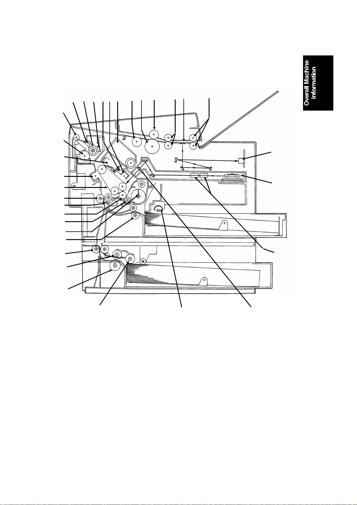
COM PONEN T LAYOUT
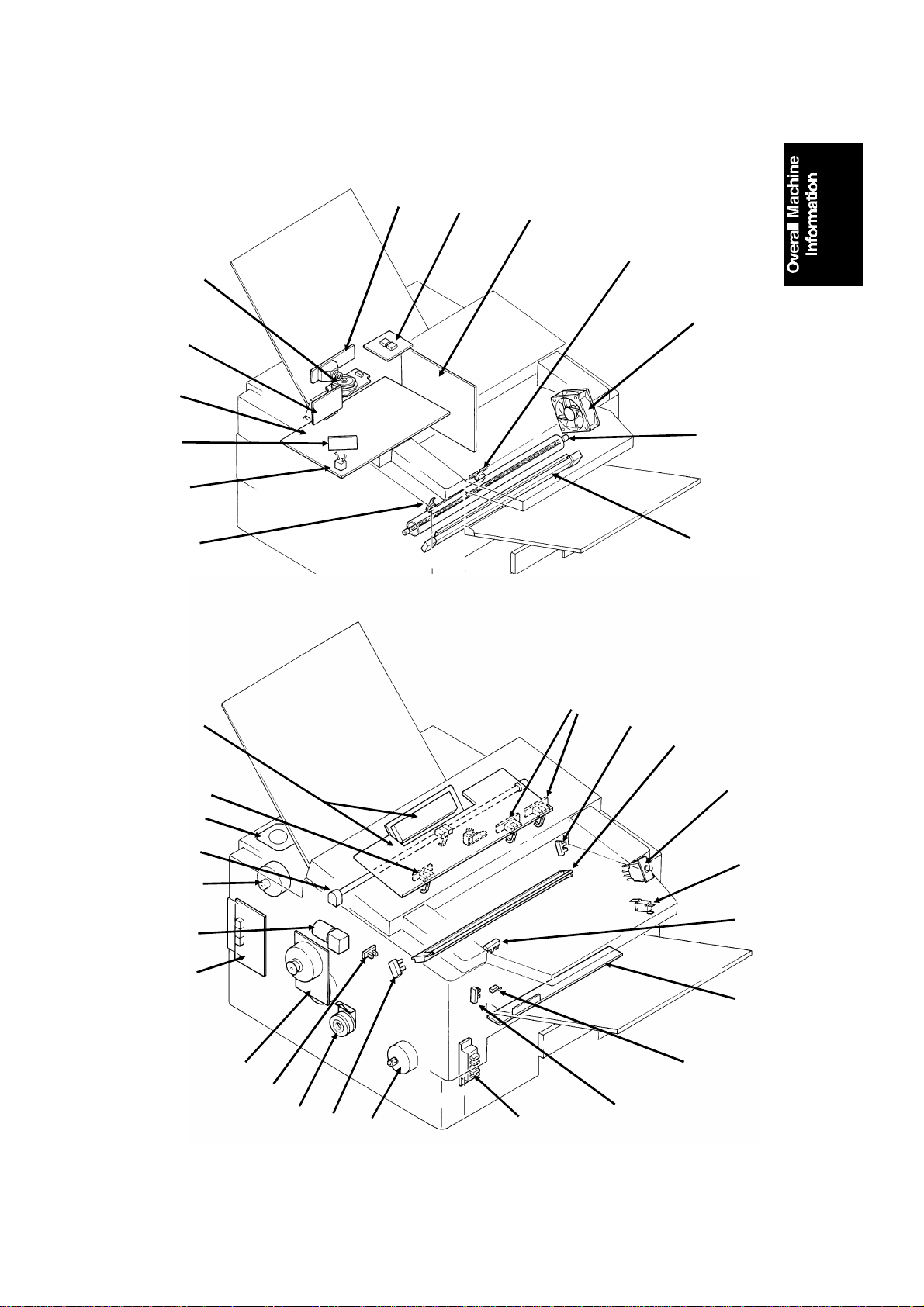
1.3. COMPONENT LAYOUT
1.3.1. Mechanical Components
13
14
15
16
17
18
19
20
21
22
23
24
12
11
10
2
6789
45
3
1
32
31
30
25
26
27
1. R2 Rollers Feed the document through the scanner.
2. Exposure Glass E xposes the original to light from the xenon lamp.
3. R1 Rollers Feed the document through the scanner.
4. Se paration Roller All ows on e pa ge in t o t he scanne r.
5. Document Feed Roller Feeds the document into the scanner.
6. Pick-up Roll er Picks up pages of the document from the docum ent
table .
7. Toner Cartridge This s upplies toner to the deve lopment unit. It is part of
the CTM (Cleaning/Toner Magazine).
8. Charge Corona Unit This applies a charge to the master at the start of the
print cycle.
9. Quenching Lamp This remove s excess charge from the master at the end
of the print cycle.
10. Thermistor This me asures the temperature in the fusing unit.
11 . Hot Roll er Heat from thi s rolle r fuses the ton er to the copy pape r.
28
29
1-5
Page 13

14th July, 1992 OVERALL MACHINE INFORMATION
COM PONEN T LAYOUT
12 . Hot Roll er S tr i ppers These take th e paper of f the h ot roll er after f using.
13. Copy Feed-out Rollers T h ese feed the paper out of the printer.
14. Pressure Roller (Fus ing) This applies pressure to the paper during the fusing
process.
15. Cleaning Unit/Used Tone r
Tank
16. T ransfer Corona Unit This applies a charge to the paper to pull the toner off
17. Master Belt Also known as the CS (Compact Seamless) Engine. The
18. Registration Rolle r This carries out the registration process.
19. Registra tion S ensor This detects when paper is approaching the registration
20. Development Roller This roller applies toner to the latent image on the
21. Toner Supply Bar This feeds toner to the development roller.
22. Toner Mixing Bar This stirs up the toner in the deve lopment unit, so that it
23. Upper Relay Rollers The se feed paper from th e upper ca ssette in t o t he
24. Lower R elay R ollers These feed paper from the lower cassette into the
25. Lower Paper Feed Roller This feeds paper out of the lower cassette.
26. Lower Paper Separation
Roller
27. Lower Paper Pick-up Roll er Thi s picks up the t op sheet of paper from the stack in
28. Upper Paper Feed Rolle r s The se pick up the top sheet of pa per f rom the st ack in
29. Focusing Lens This focuses the laser beam onto the master belt.
30. Fθ Lenses These ensure that the thickness of the laser beam is
31. Hexagonal Mirror This passes the laser beam across the mas te r be l t.
32. CCD (Charge Coupled
Device)
This removes excess toner from the master after image
transfer and stores it. It is part of the CTM
(Cleaning/Toner Magazine).
the master and onto the copy pape r.
latent image is writte n to this organic photoconductor
belt.
roller .
master belt.
does not collect into lumps.
printer .
printer.
This ensure s that only one sheet of paper at a time
leave s the l ower cas sette .
the lower cas sette and passe s it to the feed roller.
the upper cassette a n d fe ed it into the printer.
uniform across the main scan.
This converts the light reflected from the document into
an analog v ideo sign al.
1-6
Page 14

567
13
14
15
OVERALL MACHINE INFORMATION 14th July, 1992
COM PONEN T LAYOUT
1.3.2. Drive Components
18
2
1
3
4
8
9
17
16
19
12
20
10
11
1-7
Page 15

14th July, 1992 OVERALL MACHINE INFORMATION
COM PONEN T LAYOUT
1. Tx M otor This stepper motor drives the scanner.
2. R2 Roller This fe eds the original through the scanner.
3. Toner Supply Motor This dc motor drives the toner supply mechanism.
4. R1 Roller This fe eds the original through the scanner.
5. S h u tter Dri ve Gear This ensure s that th e shutter moves out of the
document feed path at the correct time.
6. Toner Supply Gea r (CTM ) This ens ures the supply of toner from the CTM into the
development unit. It is part of the CTM.
7. Clea ning Brus h Drive Gear T his drives the cleaning brush in the CTM.
8. Hot Rolle r This fuses the tone r to the copy paper.
9. Copy Fee d-out Roller This feeds printouts out of the machine.
10. Pressure Rolle r This applies pres sure to th e copy paper in the fusing
unit.
11. Regis tration Roller Drive
Gear
12. Upper Paper Feed Motor This dr ives the pape r fe ed mechanis m in th e upper
13. Development Roller Drive
Gear
14. Upper Paper Feed Roller
Drive Gear
15. Master Belt Drive Gear This drives the master belt.
16. Paper Feed Clutch This transfers drive from the upper paper feed motor to
17. Toner Supply Gear
(Development)
18. Main Motor This brushless dc motor drives the mas te r belt, fus ing
19. Lower P aper Feed Motor This drives the paper feed mechanism in the lower
20. Lower P aper Feed Clutch This transfers drive from the lower paper feed motor to
This drives the registration roller.
cassette.
This drives the deve lopme nt roller.
This drives the u pper paper f eed roller.
the uppe r paper f ee d m echanism.
This ensures the collection of toner from the CTM, a n d
its distribution across the full le ngth of the development
unit.
unit, development unit, and cleaning unit.
cassette.
the lower paper fe ed mechanism.
1-8
Page 16
9
12
16
24
OVERALL MACHINE INFORMATION 14th July, 1992
COM PONEN T LAYOUT
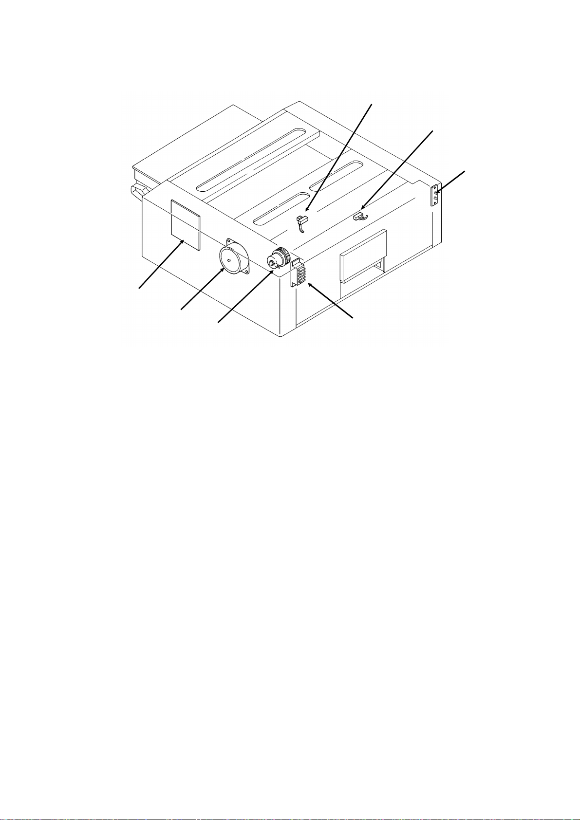
1.3.3. Electrical Components
11
10
13
8
1
2
3
4
5
6
7
34
33
32
31
37
36
35
30
29
28
27
26
14
15
17
18
19
20
21
22
23
25
1-9
Page 17
14th July, 1992 OVERALL MACHINE INFORMATION
COM PONEN T LAYOUT
Lower Ca ssette
44
43
42
Name Description No.
PCBs
FCU This board controls the machine. 11
MBU This boa rd contains the s ys te m ROM and RAM for storing
system parameters such as bit switch settings and programmed
telephone numbers .
SBU This board contains the CCD. 1
OP-PO RT This board controls the ope ration pane l. 37
NCU This board conta ins relays and switches for interfacing the
machine to the network and the handset.
PSU This board supplies power to the machine. 3
LD Unit This board drives the laser diode. 10
PF U This board controls the lower pa per f eed unit. 44
MOTORS
Tx M otor This s te pper motor drives the s canner. 33
Main Motor This dc motor drives the fusing unit, maste r belt, dev elopment
roller, and cleaning unit.
Upper Paper
Feed Motor
Lower Paper
Feed Motor
Toner Supply Mo-
tor
Hexagonal Mirror
Motor
Ozone F an This removes ozone-laden air from the vicinity of the ma ster unit,
This stepper motor drives the upper paper feed mechanism and
the registra ti on roller.
This stepper motor drives the lower pape r f eed mechanism. 43
This dc motor drives the toner supply mechanism. 32
This high-speed dc motor drive s the hexa gonal mirror in the
lase r printer optics.
an d fil t ers out th e ozone.
38
39
40
41
12
31
30
26
13
5
1-10
Page 18

OVERALL MACHINE INFORMATION 14th July, 1992
COM PONEN T LAYOUT
Name Description No.
CLUTCHES
Upper Paper
Feed Clutch
Lower Paper
Feed Clutch
SENSORS
Docum ent Sensor Th is dete cts the presence of a docume nt in t he feeder. 36
Scan Line Se ns or This detects when a page is approaching the auto shading
Document Width
Sensor
Toner Near-end
Sensor
Upper Paper Size
Detector
Upper Paper End
Sensor
Registration Sensor
Paper Feed-out
Sensor
Front Cover
Switch
CT M Sensor This detects when a C TM has been installe d in the ma chine. 27
Lower Paper Size
Detector
Lower Paper End
Sensor
Lower Paper
Feed Sensor
INT ERLOCK S WITCHES
F ron t Cove r Inter lock Switches
OTHERS
Spe aker This allows th e user to lis ten to the conditi on of th e tel ephone
Xenon Lamp This lamp illuminates the document. 34
Xenon Lamp
Driver
Charge Corona
and Quenching
Lamp Unit
Transfer Corona
Unit
Varistor This ensures that the charge given to the master by the charge
Marker This stamps a red circle on each page that is successf ully f ed
T h i s transfe rs drive from the upper paper fe ed motor to the
paper feed roller in the upper cassette.
T h i s transfe rs drive from the lower paper feed motor to the paper
fee d roller in the lower cassette.
position.
This detects when a B4-width [10.1"] or A 3-width [11.7"]
document has been placed in the feeder.
This detects when the toner has almost run out. 17
T h i s dete cts th e paper size ins talled in the upper cassette. The
use r mu st ins tall the correct actuator.
This detects when the paper in the upper cassette has run out. 29
This detects when paper has arriv ed at the registra tion rollers . 21
This detects when the paper has be en fed out of the printer . 24
This det ects whe t her the front cover is ope n or closed. 23
T h i s dete cts th e paper size ins talled in the lower casse tte. The
use r mu st ins tall the correct actuator.
This detects when the paper in the lower cas s ette has run out. 38
This sens or detects the presence of paper at th e low er paper
feed roller.
If the front cover is open, these interlock switche s inte rrupt the
+ 5VL D power s upply for th e laser di ode and the + 24VD pow er
supply for the powe r pack, motors, and oth er compon ents.
line.
This drives the xenon lamp. 2
The charge corona unit charges the ma ster belt at the start of
the print cycle . The quenching la mp removes excess charge
from the master belt at the end of the print cycle.
This pulls the toner off the maste r and onto the copy paper . 7
corona wire does not exceed -750 Volts.
through the scanner.
28
42
14
16
25
41
39
19,
20
35
18
9
15
1-11
Page 19

14th July, 1992 OVERALL MACHINE INFORMATION
COM PONEN T LAYOUT
Name Description No.
Power Pack This su pplies high voltages to the corona wires and the
development bias termina l.
F using L amp This fuses the ton er to the paper. 6
Thermistor This monitors the te mpera ture inside the fusing unit. 8
Thermostat This inte rrupts the ac power supply to the fusing lamp if the
temperature exceeds 400 °C.
Lower Ca ssette
Indicat or Panel
T h i s contains indicators to show the status of the l ower cas sette. 40
22
4
1-12
Page 20
OVERALL MACHINE INFORMATION 14th July, 1992
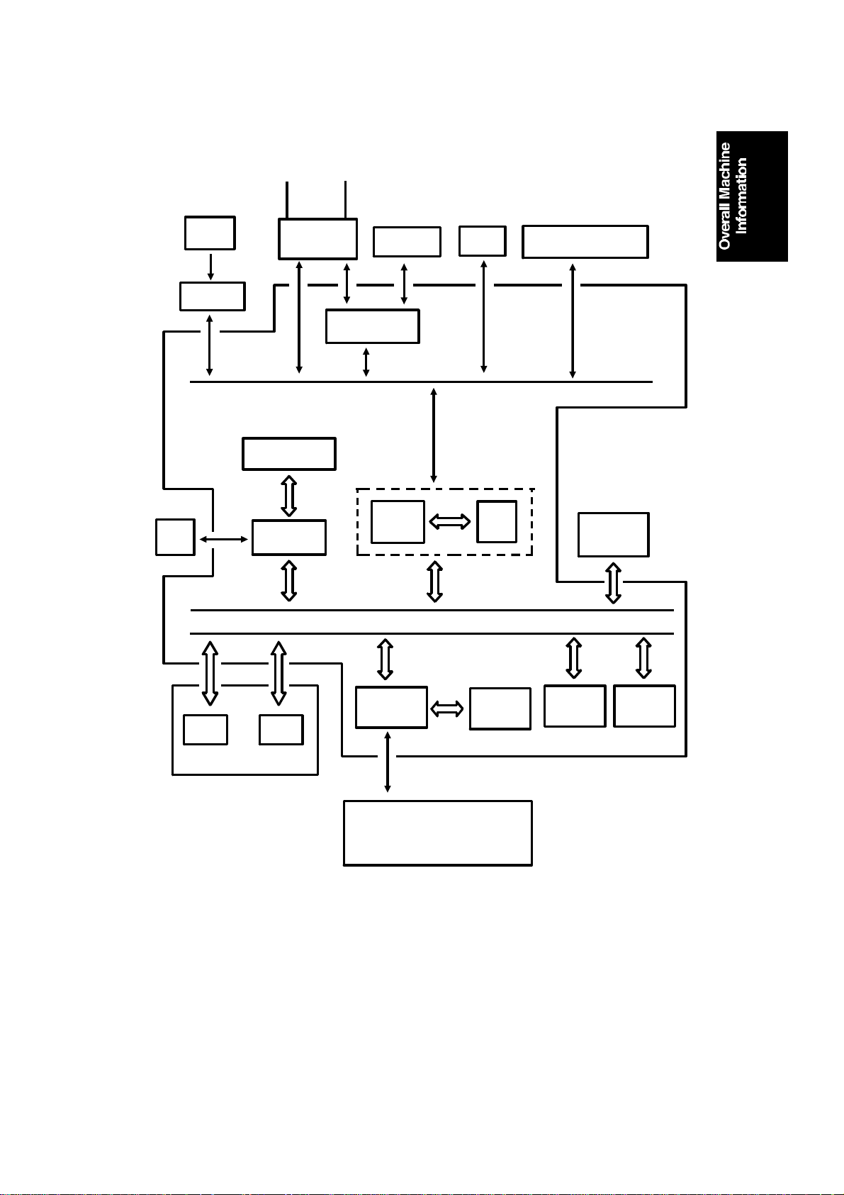
OVERALL MACHINE CONTROL
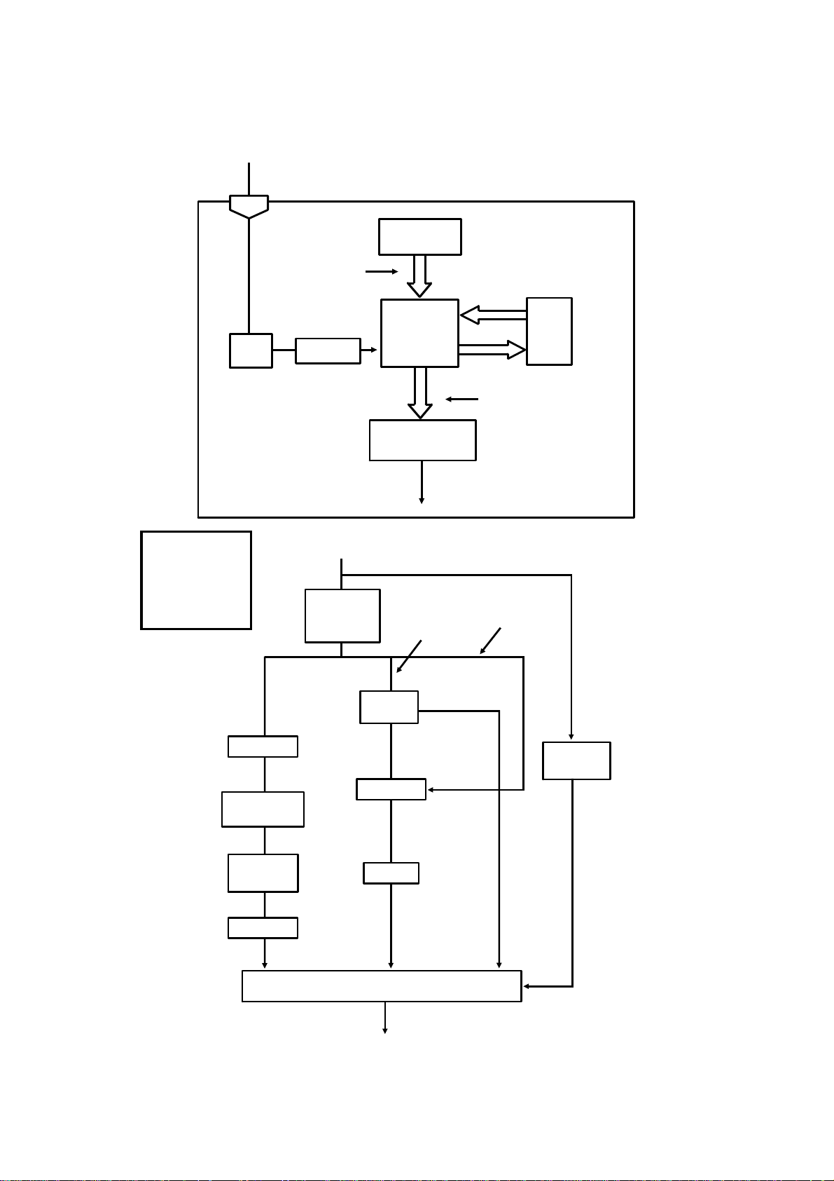
1.4. OV ERALL MACHINE CONTROL
HandsetLine
SBU
(CCD)
Scanner
Sensors
Operation
Panel
NCU
CONTROL SIGNALS
Video Processing
Memory
Video
Processor
Speaker
Modem
CPU
DATA AND ADDRESS BUS
PSU
Port
Scanner and Printer Drive
Components and Sensors
FCU
I/O
RS-232C
Interface
Laser
Interface
Page
Memory
SAF
Memory
ECM
Memory
RAMROM
MBU
Laser Diode Driver
Main Scan Start Detector
Interlock Switch
The cpu on the FCU board controls the machine, as shown in the above
drawing.
There is no modem board in the machine; the modem consists of a chip on
the FCU board that carries out all the analog and digital functions of a fax modem.
1-13
Page 21

14th July, 1992 OVERALL MACHINE INFORMATION
VIDEO DATA PATH
1.5. VIDEO DATA PA TH
1.5.1. Transmission
Original
Reference:
Group 3
Facsimile
Manual,
section
1-3-1
Xenon
Lamp
ECM
Memory
Line
Buffer
SAF
Memory
RAM
MBU
FIFO
Video
Processor
The fo llowing diagrams show
the data path for this model.
There is no programmable resis-
CCD
Analog Signal
Modem
FCU
Network
(via the NCU)
tor in this model.
CPU
To the
1.5.2. Reception
From the
Network
(via the NCU)
Reference:
Group 3
Facsimile
Manual,
section
1-3-2
Line
Buffer
RAM
MBU
FCU
Memory
SAF
FIFO
Filter
HYBRID IC
Memory
ECM
Page
Memory
Laser Diode
Modem
CPU
Laser
Interface
Laser Diode
Driver
1-14
Copy Paper
Page 22
OVERALL MACHINE INFORMATION 14th July, 1992
POWER DISTRIBUTIO N
1.6. POWER DISTRIBUTION
1.6.1. Distribution Diagram
Lower Paper Feed Motor
Lower Paper Feed Clutch
+24VD
AC Main
Power
Fusing
Lamp
PSU
AC Switching
Circuit
+24V
-12V
+24VS
+24VD
+5V
Scanner
Sensors
+5V
Operation
Panel
+5V
+24VD
Regulator
Regulator
+5V
+24VD
+5V
PFU
- 12V
+5V
+24VS
+24VS
+5V
NCU
FCU
- 5V
+12V
Sensors and
Indicators
FUSING UNIT
Thermistor
+5V
+5V
MBU
SAF Memory
+5V
SBU
+12V
+5V
Printer
Sensors
Front Cover
Interlock Switch
Front Cover
Microswitch
+5VLD
+5VLD
LDDR
Laser Diode
+24VD
Motors, Clutches, Lamps,
Marker, Power Pack
+5V
The laser diode is powered by a special + 5V supply, called + 5VLD.
There are two + 24V power supplies:
• + 24VS: This is always on when the main switch is on.
• + 24VD: This is interrupted if the front cover interlock switch opens.
There is no + 24VD activation signal fro m the cpu to the PSU.
1-15
RS-232C
Interface
Page 23

14th July, 1992 OVERALL MACHINE INFORMATION
POWER DISTRIBUTIO N
1.6.2. Memory Back-up Circuit
Reference:
Group 3
Facsimile
Manual,
sect i o n 1-4-3,
Circuit type 1
+5V
Voltage
Detector
+24V
[A]
+5V
Switching
Circuit
Regulator
MBU
RAM
1-9
1-7
Battery
Switch
Battery
Switching
Circuit
FCU
17-9
17-7
Real Time
Clock
CPU
Memory
Monitor
SAF
Memory
[B]
Battery
The battery [A] on the MBU backs up the RAM on the MBU, which contains
system parameters. It also backs up the real time clock in the cpu. This battery is not rechargeable. CN1-7 tells the cpu whether the back-up po wer
(CN1-9) comes from the battery or from the + 5V power supply.
There is no battery switch for the battery on the FCU.
A rechargeable battery [B] on the FCU board backs up the SAF memory and
the real time clock for 1 hour. While the main power is on, the + 24V supply
recharges the battery.
If there is data in the SAF memory, the rechargeable battery [B] also backs
up the real time clock, to preserve the MBU battery.
1-16
Page 24
DETAILED SECTION DESCRIPTIONS 25th June, 1992
SCANNER
2. DET AIL E D SE CTION DESCRIPTIONS
2.1. SCANNER
2.1.1. Me chanisms
1. Document Detection
[A]
Document Table
Reference:
Group 3
Facsimile
Manual,
section
2-1-1.
[B]
• Th e scanner is A3-width [11.7"], with a B4 document width d e tector [A]
and an A3 document width detector [B] .
• The scanner contains a xenon lamp.
• There is a fold-down extension [C] to support long documents.
[C]
2-1
Page 25

[A]
25th June, 1992 DETAILED SECTION DESCRIPTIONS
SCANNER
Shutter
[C]
[B]
Refere nce :
Group 3
Facsimile
Manual, section
2-1-1.
In standby mode, tab [A] r ests on cam [B]. When the tx motor starts, the motor rotates forwards (white arrows), the cam lifts the tab, and the shutter [C]
rises. After the last page has been fed through the scanner, the tx motor reverses (black arrows), the cam drops back to the standby position, and the
shutter blocks the scanner path again.
2. Pick-up and Feed
Drive Mechanism
[B]
Reference:
Group 3
Facsimile
Manual,
sect i o n 2-2-1.
[A]
[C]
This ma chine h as a Mechanical Clutch Me chanism. The tx motor [A] drives
the feed roller [B] and pick-up roller [C].
Resoluti on
Standard - Immediate transmission: The tx motor feeds the document at 200 lines per inch.
The video processor executes OR processing to convert the data into 100 lines per inch.
Memory transmission: The motor feeds the document at 100 lines per inch, and no OR processing is ne eded.
Detail - The tx motor feeds the document at 200 lines per inch. There is no OR processing,
and the data is transmitted at 200 lines per inch.
Fine - The tx motor feeds the document and transmits data at 400 lines per inch. If the other
terminal cannot receive at this re s olution, alterna te lines of data are deleted, so the effective
resolution of the transmitted data is 200 lines per inch.
2-2
Page 26

DETAILED SECTION DESCRIPTIONS 25th June, 1992
SCANNER
Jam Conditions
The cpu detects a document jam if one of the following conditions occurs.
• The scan line sensor does not switch on within 5 s of the tx motor start-
ing.
• The scan line sensor does not turn off after the maximum document
length has been fed since it turned on; this is 12 s (standard resolution),
24 s (detail), or 48 s (fine) for a 1.2 m long document.
• The scan line sensor switches on while the document sensor is off.
• The document width sensor switches on while the docum ent sensor is
off.
• The scan line sensor do es not turn on within 2 s of the end of stamping,
if the document sensor is on.
Separation
Reference: Group 3 Facsimile Manual, section 2-2-2
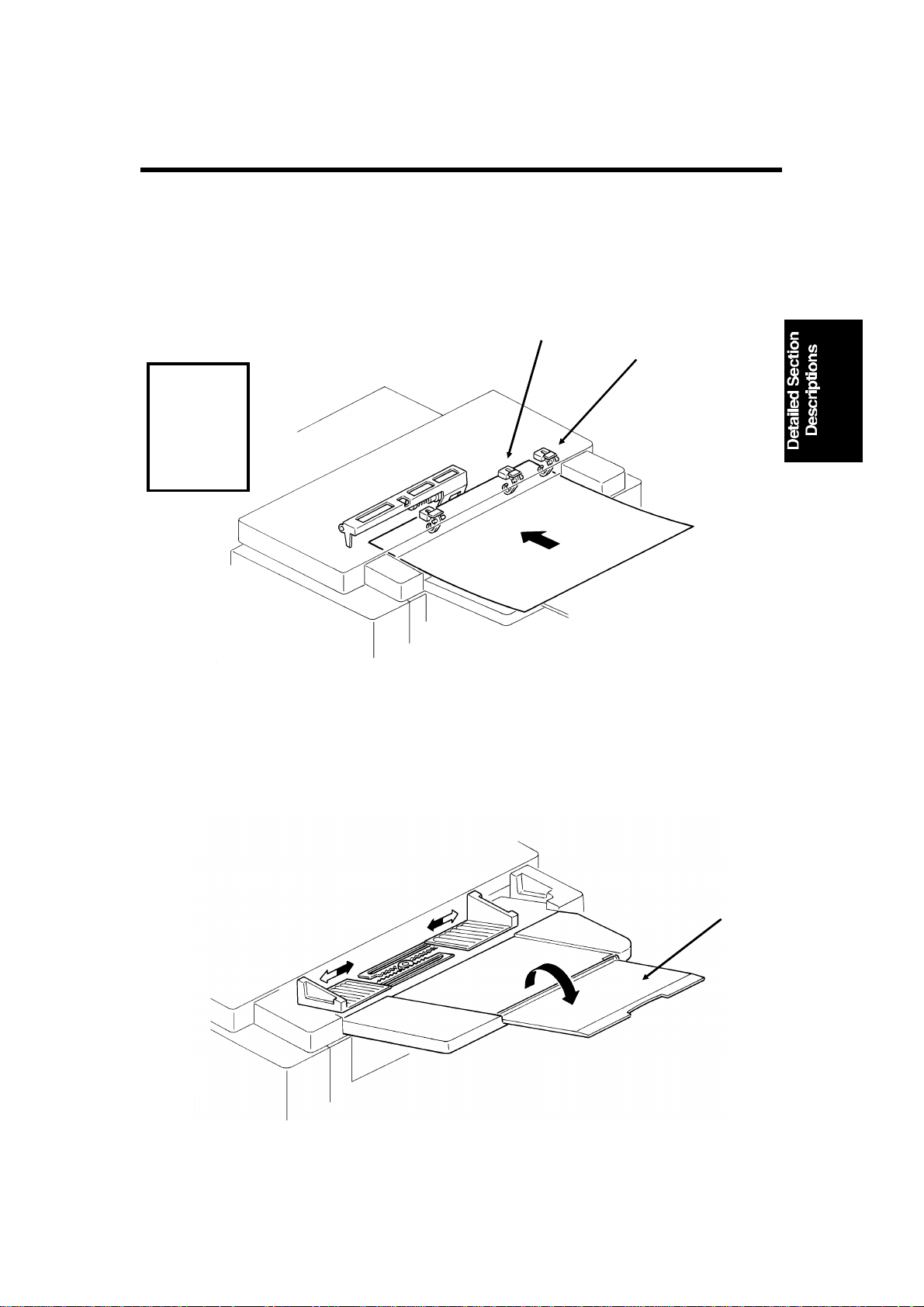
3. Manual Feed
[B]
[A]
The manual feed button [A] lifts the separation roller [B] out of the doc ument
feed path. There is no manual feed switch.
Reference: Group 3 Facsimile Manual, section 2-2-3
2-3
Page 27
25th June, 1992 DETAILED SECTION DESCRIPTIONS
SCANNER
2.1.2. Video Data Processing
Output from the CCD
A
Auto Shading
Memory
WHITE
WAVEFORM
FEEDBACK
Reference:
Group 3
Facsimile
Manual,
sect io n 2-3.
DC
Filter
VIDEO
PROCESSOR
Corrected Data from the Auto Shading Circuit
Amplifier
Gamma
Correction,
MTF
A/D
Converter
Data Processing
Circuits
Halftone
Process
Edge
Detection
To the CPU
and Modem
Basic
EDGE
ELEMENTS
Peak
Hold
CORRECTED
DATA
Error
Diffusion
Halftone
Process
Comparator
Background
Detection
OR
Processing
Reduction
A
NON-EDGE
ELEMENTS
Reduction
Halftone
B
Process Selector
To CPU and Modem
2-4
Image/Text
Detection
B’
Page 28
DETAILED SECTION DESCRIPTIONS 25th June, 1992
PRINTER
2.2. PRINTER
2.2.1. Mechanisms
1. Master Unit
This printer uses a "write to black" system, using negative toner.
The master unit contains a du rable OPC master belt. The expected lifetime of
each master unit is about 60,000 copies (this is the target value). Because of
this long lifetime, the user is not expected to change the master; there is no
Replace Master indicator.
The master belt does not have a bond seam, so no master home position detection is needed. There is also no master unit interlock switch; there is an interlock switch on the front cover.
[A]
[B]
The main motor [A] drives the master belt [B].
• At the start of printing, it turns on briefly and the master belt moves un-
der the quenching lamp to ensure that it is fully discharged.
• Then, when the fusing lamp is at the correct temperature and the page
memory contains a complete page of data, and the hexagonal mirror
motor is running at the correct speed, the main motor switches on
again.
• When the main motor is running at the correct speed, the laser diode
turns on for automatic power control.
Reference: Group 3 Facsimile Manual, section 4-1
2-5
Page 29
25th June, 1992 DETAILED SECTION DESCRIPTIONS
PRINTER
2. Charge Corona Unit
[D]
[B]
[E]
[A]
[C]
The charge corona unit [A] gives a -750 V charge to the master belt. The
varistor [B] ensures that the charge does not exceed this value.
The connection between the power pack [C] and the corona unit is not broken when the front cover is opened. However, the front cover interlock switch
cuts the + 24V power line to the power pack if the cover is opened.
The charge corona unit contains a wire cleaner [D].
The charge corona swit ches on at the same time as the laser diode starts its
power control procedure.
There is one o zone fan on the right hand side of th e machine. It sucks air out
of the machine thr ough the ozone filter, which is par t of the ozone fan assembly. The ozone fan switches on when a ringing signal is detected, and stays
on until the fusing lamp temperature falls back below 130 °C at the end of the
printing run.
The inset shows how the grid plate [E] connects to the varistor.
Reference: Group 3 Facsimile Manual, sectio n 4-2
2-6
Page 30

DETAILED SECTION DESCRIPTIONS 25th June, 1992
PRINTER
3. Laser Optics
[E]
[F]
[B]
[D]
[A]
[C]
The optics are the same as in sect ion 4-3-3 o f the Group 3 Facsimile Manual,
except that there are two mirrors [A] at the "Second Mirror" position.
Other points to note are as follows:
• Th e focusing lens [ B] is a barrel toroidal lens.
• The shield glass [C] prevents toner from entering the laser optics area,
and may need cleaning occasionally.
• An optical fiber [D] passes the reflected laser beam to the main scan
start detector [E]. This detector is situated on the laser diode drive
board [F], unlike shown in the diagram.
• The strength of the beam is 0.436 mW at a wavelength of 780 nm.
• The dimensions of the dot on the master belt are 65 µm (main scan di-
rection) by 75 µm (sub-scan direction).
The charge on the exposed parts of the belt drops to about -150 V, while nonexposed ar eas remain at about -750 V.
The laser engine characteristics are as follows (refer to page 4-3-21 of the
Group 3 Facsimile manual for background).
• Motor speed: 9,267.7 rpm (G3 and G4 l/mm mode), 9448.8 rpm (G4 dpi
mode)
• Motor type: Hexagonal
• LD clock fr equency: 5.3311 MHz
• Time between main scan synchronization signals: 1.082 ms
• Number of dots per main scan: 5769
2-7
Page 31

[A]
25th June, 1992 DETAILED SECTION DESCRIPTIONS
PRINTER
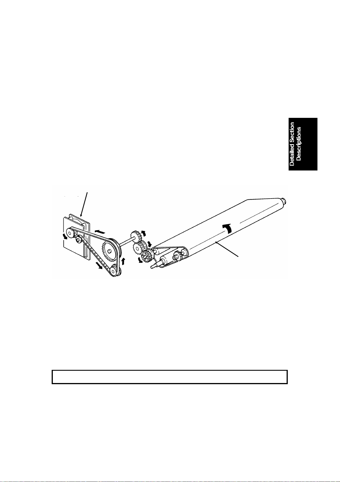
4. De velopment
Overview
This machine uses a ’write-to-black’ development system using negative
toner.
The toner cassette is part of a disposable unit known as the CTM (Cleaning/Toner Magazine). The CTM contains a toner cassette, toner supply
mechanism, cleaning unit, and used toner tank. When the toner is all used
up, the CTM is replaced.
Reference: Group 3 facsimile Manual, section 4-4
Toner Supply
[B]
[C]
[E]
[D]
When a new CTM is installed in the machine and the front cover is closed,
the main motor and to ner supply m otor turn on. When the front cover is
closed, a tab [ A] on the fusing unit cover forces the hopper [B] to open.
Also, tab [C] on the CTM pushes bracket [D], which mo ves the CTM sensor
actuator into the sensor.
Continued on the next page
2-8
Page 32

DETAILED SECTION DESCRIPTIONS 25th June, 1992
PRINTER
[F]
[H]
[I] [J]
[G]
[K]
The toner supply motor [F] drives the toner supply shaft ([E] in the diagram
on the previous page). This spiral shaft feeds toner to the hopper.
Inside the development unit is another spiral shaft [G]. This shaft, driven by
the main motor, distributes toner across the length of trough [H]. The toner
supply motor drives gear [I], and once every rotation, it tips the trough upside down, dropping the toner into the development unit. A spring immediately pulls the trough back upright so that it can continue to receive toner.
The toner mixing bar [J], driven by the main motor, keeps the toner agitated
as it builds up at the bottom of the development unit. The toner supply bar
[K] supplies toner to the development roller.
While toner is being supplied, the main motor is also operating the toner nearend detection mechanism. When a fresh toner cassette is installed, the sensor detects toner near-end, because there is not much toner in the
development unit. When some toner has been transferred, the signal from
the toner near-end sensor returns to normal. About 22 s after that, the toner
supply motor stops and no more toner is transferred into the development
unit.
During printing, if toner near-end is detected, the toner supply me chanism will
start up again. Toner will be supplied until the sensor signal returns to normal. If the toner cassette in the CTM is empty, no toner will be transferred,
and the sensor signal will not return to normal. If the sensor outputs the nearend signal for more than 5 minutes, the cpu blinks the Add Toner indicator.
See "To ner Near-end Detection" for m ore details.
2-9
Page 33

25th June, 1992 DETAILED SECTION DESCRIPTIONS
PRINTER
Development Unit Drive
[A]
[B]
During printing, dr ive from the main motor at gear [A] drives the development
roller [B]. The main motor also drives the master belt, so the development
roller and the master belt always move at the same time; therefore, no development clutch is needed.
Toner Near-end Detection
The toner near-end detection mechanism is exactly the same as described in
section 4-4-4 of the Group 3 Facsimile Manual. The sensor signal is as
shown in the following diagram.
Reference:
Group 3
Facsimile
Manual,
sect i o n 4-4-4.
1.9 s
0.1 ms
The cpu starts to blink the Add Toner indicator under the following conditions:
• At power up: If the sensor output indicates toner near-end for 6 s
• During printing: If the sensor output indicates toner near-end for more
than 5 minutes, totaled over consecutive print runs (when the motor
stops, the sensor mechanism is deactivated, so time between printing
runs does not count towards the 5 minute time limit)
After 100 more pages have been printed, the Add Toner indicator remains lit,
and printing is disabled until a new CTM has been added.
2-10
Page 34

DETAILED SECTION DESCRIPTIONS 25th June, 1992
PRINTER
Development Bias
[B]
[A]
The development bias and switching bias are supplied from the power pack
[A] at the same terminal [B].
• Development bias: - 530 ± 20 Vdc (BIASL)
• Switching bias: + 70 ± 20 Vd c (BIASH)
The switching bias is used at the following times:
• Between pages of a print run, while the development bias is off
• While toner is being transferred from the CTM to the development unit
2-11
Page 35

25th June, 1992 DETAILED SECTION DESCRIPTIONS
PRINTER
5. Paper Feed
There are two cassettes, a 250-sheet cassette, and a 500-sheet cassette. In
some models, the 500-sheet cassette is an optional unit.
The sizes of paper that the cassettes can take are listed in the specifications
(section 1- 1).
[A]
Paper feeds from the rear towards the front. The lower paper feed path
bends upward thro u gh the front part of the upper cassette. The two paper
feed paths merge just before the registration roller [A].
2-12
Page 36

[B]
[B]
DETAILED SECTION DESCRIPTIONS 25th June, 1992
PRINTER
Paper Lif t
Standard Cassette
[C]
[A]
A mec hanical paper lift mechanism is used. When the user places the cassette into the machine, a pin [A] in the base of the cassette activates a spring
loaded lever mechanism [B], which forces up the paper lift arm [C] until the
top of the stack touches the paper height positioner.
Lower Cassette
[A]
[D]
[C]
[E]
A mec hanical paper lift mechanism is used. When the user places the cassette into the machine, a tab [A] on the rear of the cassette pushes a plate
[B] towards the rear of the machine as the user slides in the cassette. This
plate, driven by a spring [C], forces up the paper lift arm [D]. The paper
height positioner [E] ensures that the paper is not pushed up too far.
Reference: Group 3 Facsimile Manual, section 4-5-2
2-13
Page 37

25th June, 1992 DETAILED SECTION DESCRIPTIONS
PRINTER
Pick-up and Feed Mechanism
Standard Cassette (Clutch Driven Single Roller Mechanism)
Reference:
Group 3
Facsimile
Manual,
sect io n 4-5-3.
[B]
[D]
[G]
[C]
[A]
[E] [F]
The upper paper feed motor [A] drives the pick-up and feed mechanism. The
paper feed clutch [B] transfers drive from this motor to the feed rollers [C].
When the paper feed clutch tu rns on, a metal plate [D] moves away from
gear [E]. A pin [F] on this plate releases the gear, and the paper feed roller
turns. However, the clutch switches off after only 0.3 s, and a spring forces
the plate back to the starting position. After one revolution, the rib [G] on the
inside of the gear comes against the pin, and the paper feed roller stops.
When the page memory is full, the upper paper feed motor turns on. At the
beginning, it rotates at a slower speed (202.5 pps) to avoid excessive startup noise and start-up current peak.
At 0.1 s after the main motor reaches the correct speed, the motor turns at a
higher speed (405 pps). This higher speed, used for pick-up and feed, ensures that time is not wasted getting paper into the printer. At the same time,
the upper paper feed clutch turns on and paper is fed into the printer.
Shortly after the registration sensor turns on, the main motor has the leading
edge of the paper, so the upper paper feed motor rotates at 202.5 pps again
to match the feed speed of the main motor.
When the trailing edge of the paper h as left the registration s ensor, the p a per
is no longer affected by the upp er paper feed motor. The upper paper feed
motor goes back to 405 pps ready fo r feeding the next page.
2-14
Page 38

DETAILED SECTION DESCRIPTIONS 25th June, 1992
PRINTER
Lower Cassette (Clutch Driven Two Roller Mechanism)
Reference:
Group 3
Facsimile
Manual,
sect io n 4-5-3.
[A]
[C]
[D]
[E]
[B]
The lower paper feed motor [A] drives the lower paper feed mechanism, and
the lower paper feed clutch [ B] transfers drive from the motor to the lower
pick-up [C] and feed [D] rollers at the correct time.
When the page memory is full, th e lower paper feed motor turns on. At the
beginning, it rotates at a slower speed (266 pps) to avoid excessive start-up
noise and start-up cur rent peak. After 0.1 s, the m otor rotates at a higher
speed (800 pps). This higher s peed o f rotation, used during pick-up and
feed, ensures that little time is wasted in getting paper out of the cassette and
into the printer.
When main motor lock is achieved, the lower paper feed clutch turns on and
paper is fed into the prin ter. Shortly after the pa per feed sensor [E] is activated, the clutch turns off.
After registration, the upper paper feed and main motors turn o n to drive the
registration ro llers and feed the paper into the printer. However, rollers driven
by the lower paper feed motor still hold the trailing edge of the paper. So the
lower paper feed motor rotates at 266 pps t o match the feed speed of the upper feed and main motors.
When the trailing edge of the paper h as left the paper feed sensor, the paper
is no longer affected by the lower paper feed mo tor. The lower paper feed
motor goes back to 800 pps ready fo r feeding the next page.
2-15
Page 39

[B]
25th June, 1992 DETAILED SECTION DESCRIPTIONS
PRINTER
Separation Mechanism
Standard Cassette
The standard cassette uses a semicircular roller and corner separator
method of separation.
Lower Cassette
This cassette uses a feed and revers e roller mechanism.
Reference: Gro up 3 Facsim ile Manu al (sect ion 4-5-4).
Registration
[C]
[D]
Reference:
Group 3
Facsimile
Manual,
sect io n 4-5-5.
[A]
[E]
Standard Cassette
There is no registration. This is because the upper paper feed m otor [A]
drives the registration roller [ B] and the upper paper feed rollers [C], and
there is no registration clutch. This means that the registration roller and the
paper feed rollers stop at exactly the same time.
Just after the paper’s leading edge reaches the registration sensor [D], the
upper paper feed motor stops briefly.
Lower Cassette
The upper paper feed motor is off when the leading edge of the paper acti-
vates the registration sensor. The lower paper feed roller [E] continues to
feed the pape r for a s hort while after th is, so registration is done in the normal manner (s ee section 4-5-5 of the Group 3 Facsimile Manual) .
2-16
Page 40

[A]
DETAILED SECTION DESCRIPTIONS 25th June, 1992
PRINTER
Jam Detection
The machine detects a jam if one of the following conditions exists.
• The registration sensor or copy feed-out sensor is activated while the
machine is in standby mode.
• The registration sensor st ill detects pap er 9.0 s after the paper feed
clutch turned on.
• The copy feed-out sensor still does not detect paper 9.0 s after the pa-
per feed clutch turned on.
• The copy feed-out sensor still detects the presence of paper 9.0 s after
it first detected the latest sheet of paper.
• Standard Cassette Only: The registration sensor does not turn on within
2.0 s after the upper paper feed clutch turned on.
• Lower Cassette Only: The lower paper feed sensor does not turn on
within 1.2 s after the lower paper feed clutch turned on.
There is no error detectio n during paper lift.
Paper Size Detection
Reference:
Group 3
Facsimile
Manual,
sect io n 4-5-9.
[B]
For both cassettes, the paper size actuator [ A] is on the front of the cassette.
The pa per size sensor [B] is a row of microswitches. The above diagram
shows the upper paper size sensor.
The cpu disables paper feed from a cassette if the paper size cannot be detec ted. If the paper size actuator is missing or b roken, or if there is no cassette in the cavity, the Add Paper indicator will light.
2-17
Page 41

Lower Cassette
25th June, 1992 DETAILED SECTION DESCRIPTIONS
PRINTER
Paper End Detection
Upper Cassette
[A]
[B]
Reference: Grou p 3 Fac sim il e Manu al, sec t io n 4-5-8.
[A]
[B]
In both cassettes, the paper end sensor actuator [A] falls through a slot [B]
in the bottom of the tray.
There are no paper height sensors or paper near-end sensors.
Page Separation and Data Reduction
Incoming pages that are similar in length to the copy paper may be reduced
in the sub-scan direction to fit on the paper. Whether or not this happens depends on the settings of bits 1 and 2 of bit switch 02.
Reduction Enabled
If bit 2 of bit switch 02 is at 0, the data will be red uced in the page memory t o
fit on the copy paper. However, data will only be reduced if the length of the
incoming page is between 5 mm shorter and a certain maximum length. This
maximum incoming page length that can be reduced depends on the copy
paper size and on the reduction ratio s tored in RAM address es 00014F and
000150.
Each paper size can be programmed with a separate reduction ratio. In each
of the two RAM addresses, there is one bit for each possible paper size. The
comb ination of the bit settings determines the ratio for that paper size.
Bit 7: Not used Bit 5: Legal Bit 3: A4 Bit 1: B5
Bit 6: B4 Bit 4: F4 Bit 2: Letter Bit 0: A5
The ratio is determined in accord ance with the following table.
Bit in 00014F 0: Not used 1: 4/3 0: 8/7 1: 12/11
Bit in 000150 0 0 1 1
2-18
Page 42

DETAILED SECTION DESCRIPTIONS 25th June, 1992
PRINTER
The following table shows the maximum incoming page lengths that can be
reduced for each copy paper size. All lengths are in millimetres. The factory
setting of the reduction ratio is 4/3.
Copy
Pap er Type
A5 148 190.7 163.4 156
B5 182 236 202.3 193.1
Letter 279.4 365.9 313.6 299.3
A4 297 389.3 333.7 318.5
F4, F 330.2 433.6 371.7 354.8
Legal 355.6 467.5 400.7 382.5
B4 364 478.7 410 391.6
Copy Paper
Length
Maximum reducible incoming page le ngths
Ratio = 4/3 Ratio = 8/7 Ratio = 12/11
The values are calculated as follows.
Maximum incoming page length that can be reduced =
(Copy Paper Length - 5) x Reduction Ratio
For example, for A5 with a reduction ratio of 4/3
Max incoming data length = (148 - 5) x 4/3 = 190.7
Incoming pages that are longer than the maximum length will not be reduced, but will be printed on two pages and treated in accordance with the
setting of bit 1 of bit switch 02. If this bit is 1, the bottom few lines of the page
will be repeated at the top of the next page. If this bit is 0, the next page will
continue from where the first page left off.
Reduc tion Disabled
If bit 2 of bit switch 02 is at 1, the data will not be reduced. However, if the in-
coming page is up to x mm longer than the copy paper, the excess portion
will not be printed. The value of x can be from 0 to 15 mm . It is determined by
the setting of RAM address 000151 (copy mode: bits 3 to 0, receive mode:
bit s 7 to 4; bits 3 an d 7 are the most significant bits).
Hex value Value of x
0 0
1 1
and so on until
15 15
Messages more than x mm longer than the copy paper will be printed out on
two pages in accordance with the setting of bit 1 of bit switch 02, as explained above.
2-19
Page 43

25th June, 1992 DETAILED SECTION DESCRIPTIONS
PRINTER
Paper Size Selection
If there are two cassettes in the machine, the paper size to use is decided in
accordance with a few simple rules.
• If both cassettes contain the same paper size, the lower cassette will be
used.
• If the received page has to be split up and printed on two pages, both
pages will be the same size.
• If the cassettes contain different sizes, the paper size chosen for print-
ing the received fax message is selected in accordance with the following table of priorities. The table assumes that reduction is enabled and
that the reduction ratio is 4/3.
Paper Size
A5 Letter A4 F, F4 Legal B4
Recv’d
Fax
Message
Size
A5123456
Letter6(SR)12345
A4 6(SR) 2(R) 1 3 4 5
F, F4 6(SR) 5(R) 4(R) 1 2 3
Legal 6(SR ) 5(R) 4(R) 3(R) 1 2
B4 6(SR) 5(R) 4(R) 3(R) 2(R) 1
• 1 is top priority.
• S: The data has to be separated and printed on more than one page.
• R: The data is reduced to fit on the printer paper.
• If Specified Cassette Selection has been switched on, messages from
specified senders will always go to the upper cassette, regardless of the
paper size or message size.
• Some of the reports can be printed on A5 paper without page separa-
tio n. However, if only A5 paper is in the cassettes, reports that need
larger paper sizes will require page separation.
2-20
Page 44

DETAILED SECTION DESCRIPTIONS 25th June, 1992
PRINTER
6. Transfer Corona Unit
[B]
[A]
The voltage of the transfer corona unit [A] is between 3.8 and 5.5 kV. It gives
a 200 V charge to the paper to pull the negative toner off the master belt. The
bend [B] in the master belt also helps the paper to leave the belt. There is no
antistatic brush to aid separation.
Reference: Group 3 Facsimile Manual, section 4-6
2-21
Page 45

25th June, 1992 DETAILED SECTION DESCRIPTIONS
PRINTER
7. Fusing Unit
Fusing Unit Drive
[A]
The main motor [A] drives the fusing unit through a train of gears.
Fusing Unit Control
• Stan dby t emperature: 80 °C
• Printing start tem perature: 150 °C
• Maximum print ing temperature: 170 °C (monitored by a comparato r)
• Thermistor maximum: 280 °C
• Thermostat maximum: 400 °C
When the main power is switched on, the fusing lamp heats up to 80 °C in
about 10 s.
When a ringing signal is detected (or when the user presses Start or Copy
for taking a copy), the fusing lamp heats up to 150 °C in about 15 s.
At the end of printing, the ozone fan stays on until the fusing unit temperature
has falle n belo w 150 °C.
Reference: Group 3 Facsimile Manual, section 4-7
2-22
Page 46

[A]
DETAILED SECTION DESCRIPTIONS 25th June, 1992
PRINTER
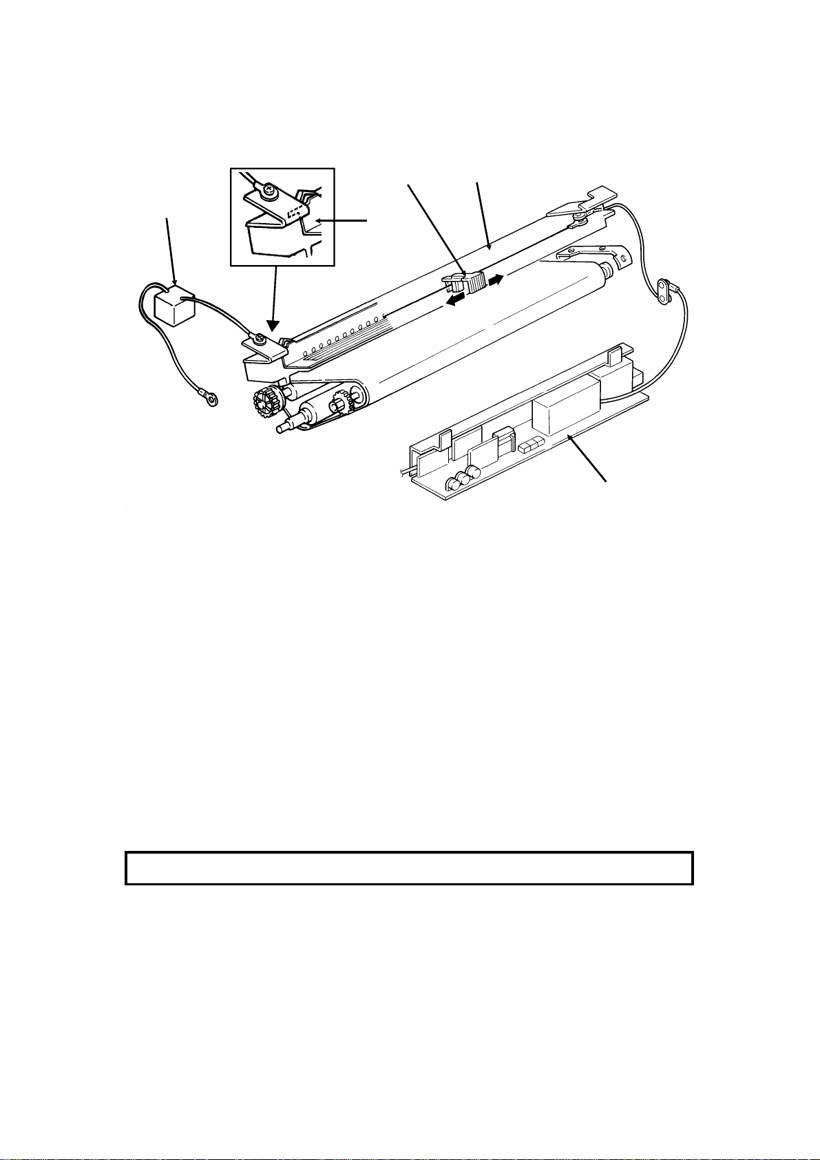
8. Cleaning
[C]
[B]
[C]
[A]
The CTM contains the cleaning unit and the used toner tank.
When the CTM is out of the machin e, the clean ing blade [A] is forced against
a mylar plate, which prevents used toner from falling out.
When the CTM is placed inside the machine, a tab on the copy exit cover
pushes plate [B], which moves the cleaning blade away from the mylar and
against the master belt.
The cleaning blade wipes toner off the master belt as it passes the cleaning
unit. The toner goes to the used toner tank. The cleaning roller [C], driven by
the main motor removes any toner that may remain attached to the cleaning
blade.
There is no toner overflow detection mechanism. This is bec ause the used
toner tank is removed with the old CTM when the toner cassette is empty;
the toner near-end sensor detects this.
Reference: Group 3 Facsimile Manual, section 4-9
2-23
Page 47

25th June, 1992 DETAILED SECTION DESCRIPTIONS
PRINTER
9. Quenching
[A]
[B]
The quenching lamp [A] is an LED array. After quenching, the charge on the
master [B] is about -20 V.
Reference: Group 3 Facsimile Manual, section 4-10
2-24
Page 48

DETAILED SECTION DESCRIPTIONS 25th June, 1992
PRINTER
2.2.2. Circuits
1. Laser Diode
Laser Diode Drive
Front Cover
Interlock Switch
AC/DC
Converter
+24V
1-1
Front Cover
Microswitch
PSU
1-2
3-8
2-1
FCU
+5V
1-1
+24VD
20-5
+5V
8-1
+5VLD
8-2
9-1
1-8
LDDR
Laser
Diode
Controller
Laser
Diode
The laser diode is powered by a special + 5V supply, called + 5VLD.
There are two switches activated by the front cover; the front c over int erlock
switch, and the front cover microswitch. If either of these switches is open,
the power supply to the laser diode is interrupted.
The laser diode is not started until the following conditions have been met:
• Th e main and hexagonal mirror motors are rotating at the correct
speeds
• The page memory contains a complete page
• The fu sing lamp is at the printing tem perature
2-25
Page 49

25th June, 1992 DETAILED SECTION DESCRIPTIONS
PRINTER
Laser Diode Power Control
Laser
Power
Controller
1-2 1-4 1-5
DATA
CONTROL FEEDBACKDISABLE
Laser
Interface
Laser
Diode
LDDR
1-6
9-49-59-7
9-3
FCU
I/O
Port
CPU
The Laser Interface sends a constant signal to the laser diode on CN9-7, forcing the diode to stay on. The feedback signal returns to the FCU on CN9-3. If
necessary, the cpu adjusts the laser diode power to the correct value by altering the control signal (CN9-4).
If the cpu determines that laser diode power control has failed, it sends CN95 to low, which disables the laser diode.
Service Note
If one of the following occurs, the printer will be disabled, and an Auto Service Call will be sent to the service station (the message will be LD POWER
CONTROL FAILURE).
• If there is no response to laser power control (the cpu sends CN9-5
low).
• If the laser diode power supply (+ 5VLD) is cut.
2-26
Page 50

DETAILED SECTION DESCRIPTIONS 25th June, 1992
PRINTER
2. Fusing Unit
FUSING UNIT
Fusing
Lamp
Thermistor
36-2
+5V
36-1
LIVE
NEUTRAL
170 C [A]
4-1,4
4-3,6
36-3
I/O
Port
PSU
AC Switching
Circuit
3-1
36-4
3-2
1-8
Main
Power
Supply
1-7
FCU
The circuit shown in the above diagram controls the fusing unit.
• The I/O Port monitors the fusing unit temperature at CN36-1.
• The signal from the comparator [A] remains high if the fusing unit tem-
perature is below 170 °C.
• The I/O Port switches the fusing unit on/off using the signal on CN1-8.
• If the thermistor is accidentally disconnected, the link between CN36-3
and CN36-4 will also be broken. When the cpu detects this, an Auto
Service Call will be s e nt.
Standby mode
• If the fusing lamp is below 80 °C, the I/O Port makes CN1-8 go high.
This switches on the fusing lamp.
• If the fusing lamp goes above 80 °C, CN1-8 goes low, which switches
off the fusing lamp.
Continued on the next page
2-27
Page 51

25th June, 1992 DETAILED SECTION DESCRIPTIONS
PRINTER
Printing
• When a ringing signal is detected, CN1-8 goes high, to switch on the
fusing lamp. Also, the ozone fan switches on.
• During printing, the temperature is kept at 170 °C. If the temperature
rises above 170 °C, the output from the comparator changes state. This
causes CN1-8 to go low, which switches off the fusing lamp.
• If the comparator fails, there are additional safety cutoffs at 280 °C (ther-
mistor) and at 400 °C (thermostat).
After printing
• When the fusing lamp temperature falls back below 150 °C, the ozone
fan switches off.
Service Note
When an error occurs, the I/O Po rt switches off the fusing lamp by raising
CN1-7 to high. The printer will be disabled, and an Aut o Service Call will be
sent to the service station (the message will be HOT ROLLER DOWN). Details concerning these errors are given in s ection 6-3 (Service Call C onditions).
2-28
Page 52

DETAILED SECTION DESCRIPTIONS 25th June, 1992
PCBs AND THEIR FUNCTIONS
2.3. PCBs A ND THEIR FUNCTIONS
2.3.1. FCU
HandsetLine
SBU
(CCD)
Scanner
Sensors
Operation
Panel
Speaker
CONTROL SIGNALS
Video Processing
Memory
Video
Processor
Modem
NCU
CPU
HIC
PSU
I/O
Port
Scanner and Printer Drive
Components and Sensors
FCU
RS-232C
Interface
MBU
DATA AND ADDRESS BUS
Laser
Interface
Page
Memory
SAF
Memory
ECM
Memory
RAMROM
Laser Diode Driver
Main Scan Start Detector
Interlock Switch
2-29
Page 53

25th June, 1992 DETAILED SECTION DESCRIPTIONS
PCBs AND THEIR FUNCTIONS
1. CPU (MFCP)
• 65C02 compatible microprocessor
• Interrupt control
• DMA control
• Data compression and reconstruction (high speed MH coding for 2.8-
second scanning)
• Real time clock (battery backed-up)
• Memory control
• Control of all mechanisms (directly or through other chips)
• NCU control (through the I/O Port)
2. I/ O Port (MIOP)
• Clock control
• Sensor monitoring (including A/D conversion where necessary)
• Tone detection
• Moto r drive
• Operation panel c ontrol
• Laser Interface control
3. Laser Interface (LIF)
• Page memory control
• Laser diode control
• Smoothing
4. Modem
• Modulation/demodulation (analog/digital processes)
5. Video Processor (VPP)
• Analog/digital video signal processing
6. Hybrid IC (HIC)
• Filters
• Amplifiers
7. RAM
• 256k for ECM and system RAM (no back-up)
• 1 Mbyte SAF memory (with battery back-up)
• 1 Mbyte page memory
• 24 kbyte image memory for the VPP
2-30
Page 54

DETAILED SECTION DESCRIPTIONS 25th June, 1992
PCBs AND THEIR FUNCTIONS
2.3.2. MBU
System
ROM
DATA AND ADDRESS BUS
Memory Back-up
Control
+
To/From
FCU
1. System ROM
• Contains the software to run the machine
MBU
System
RAM
To/From
FCU
2. System RAM
• 1 Mbit SRAM for parameter storage, line buffer, FIFO, SAF memory ad-
ministration
The SRAM is backed up by the battery on the MBU.
2-31
Page 55

25th June, 1992 DETAILED SECTION DESCRIPTIONS
PCBs AND THEIR FUNCTIONS
2.3.3. SBU
Analog Video
To the FCU
Drive Clocks
From the FCU
Drivers
CCD
+12V
+12V
+
Emitter
Follower
Inverter
Amplifier
SBU
2.3.4. OPU
LCD Panel
LCD Panel
Controllers
Operation Panel
Keys
Operation Panel
Operation Panel
Controller
Serial Interface
To/From FCU
LEDs
Output
from the
Scanner
Sensors
2-32
Page 56

DETAILED SECTION DESCRIPTIONS 25th June, 1992
PCBs AND THEIR FUNCTIONS
2.3.5. LDDR
2.3.6. PFU
Lower Cassette
Sensors
DATA
Laser
Power
Controller
CONTROL
To/From FCU
PFU
POWER
Indicator
Panel
Lower Cassette
Controller
Driver
Laser
Diode
LDDR
Lower Cassette
Mechanical
Components
Serial Interface
To/From FCU
2-33
Page 57

25th June, 1992 DETAILED SECTION DESCRIPTIONS
PCBs AND THEIR FUNCTIONS
2.3.7. NCU
TIP
RING
T1
R1
To
Network
To
Handset
Protection
Circuit
FG
Line
Current
Detector
Oh
Relay
Di Switch
Ringing
Signal
Detector
Tx/Rx Data
To/From FCU
To FCU
+24V
Off-Hook
Detector
From FCU
To FCU
NCU
• For simplification, relay drive signals and detector outputs to/from the
FCU are not shown on this diagram.
• In the above diagram, the relays are shown in the standby position for
Auto Receive (Fax) Mode.
2-34
Page 58

DETAILED SECTION DESCRIPTIONS 25th June, 1992
PCBs AND THEIR FUNCTIONS
2.3.8. PSU
LIVE
NEUTRAL
GROUND
AC Power
to the
Fusing Lamp
Prevention
Arrestor
Fusing Lamp
Enable
From FCU
Surge
+24VD
AC Switching
Circuit
To
FCU
Main
Switch
+24VD
From
Front Cover
Interlock
Switch
Noise
Filter
+24V
To
Front Cover
Interlock
Switch
Surge Current
Prevention
+24V
To
FCU
Power Supply
Generation
Circuits
+5V
To
FCU
PSU
-12V
To
FCU
Overhea t Protection in the PSU
If the PSU thermistor temper ature exceeds about 100 °C, the power supply
outputs from the PSU are disabled.
If this happens:
1. Switch off the machine.
2. Take out the PSU and examine it for damage. Take care because it may
be hot.
3. Put back the PSU and switch the machine on. If the machine does not operate, change the PSU.
2-35
Page 59

INSTALLATION 25th June, 1992
CONNECTING UP THE MACHINE
3. INSTA LLA TION
3.1. CONNECTING UP THE MACHINE
POWER SWITCH
115 ± 20V
60 ± 1 Hz
Grounded
Phone
Company’s
Jack
HANDSET
3-1
Page 60

[B]
[A ]: 1 screw
25th June, 1992 INSTALLATION
INSTALLING ADDITIONAL UNITS
3.2. INSTALLING ADDITIONAL UNITS
3.2.1. Lower Cassette
Check whether there are any messages in the memory. If there are, you
must install the lower cassette and turn the power back o n within an hour.
[A ]
[B]
[D]
[C]
[C]
Fit pegs [B] into holes [C].
[D]: 5 screws
3-2
Page 61

[F]
[G]
[H]
INSTALLATION 25th June, 1992
INSTALLING ADDITIONAL UNITS
[F]
[E]
[E]: 2 conne ct o rs
Re move two screws [F].
[G]
Install brackets [G] (2 screws each).
[I]
3-3
Page 62

25th June, 1992 INSTALLATION
INSTALLING ADDITIONAL UNITS
[J]
Adjust the cassette in accordance
with customer requirements.
3-4
Page 63

INSTALLATION 25th June, 1992
INSTALLING ADDITIONAL UNITS
Up to 4 of these paper feed units can be added to the machine. However, if
more than one is installed, you have to install drawer and base units in one of
the following ways.
Machine
Paper
Feed
Units
Base
2 Paper
Feed Units
Drawers
3 Paper
Feed Units
4 Paper
Feed Units
3-5
Page 64

25th June, 1992 INSTALLATION
INSTALLING ADDITIONAL UNITS
3.2.2. Memory Card
• Tur n off the power before installing or removing a memory card.
• Make sure that 100% is displayed on the operation panel before install-
ing or removing a memory card, or data will be lost.
3-6
Page 65

INSTALLATION 25th June, 1992
INSTALLING ADDITIONAL UNITS
3.2.3. Cassette (250 Sheets)
3-7
Page 66

25th June, 1992 INSTALLATION
INSTALLING ADDITIONAL UNITS
3.2.4. Cassette (500 Sheets)
3-8
Page 67

[B]: 2 screws
INSTALLATION 25th June, 1992
INSTALLING ADDITIONAL UNITS
3.2.5. Handset
[A]
[A]: 2 screws
[B]
3-9
Page 68

[C]
25th June, 1992 INSTALLATION
INSTALLING ADDITIONAL UNITS
3.2.6. Hard Disk
The installation has three phases.
• SAF Memory Initialization
• Installation Procedure
• Software Initialization
SAF Memory Initialization
1. Function 6 0 1 9 9 1 then immediately Yes
2. 0 1
3. Set bit 2 of bit switch 00 to 1.
4. Yes Function
Installation Proc edure
Switch off the power and unplug the machine from the wall socket. Then remove the cassettes.
[A]
[D]
[B]
[F]
[G]
[E]
3-10
Page 69

INSTALLATION 25th June, 1992
INSTALLING ADDITIONAL UNITS
[ I ]
[H]
Before attaching [J], remove the side covers of
the paper feed unit.
Then, after attaching [J],
put the covers back.
[L]
[N]
[N]
[K]
Change the ROM [L]
on the HDIF board before reassembling the
hard disk unit.
[J]
[M]
Caution: Do not p lug in or switch on until everything is connected up.
3-11
Page 70

25th June, 1992 INSTALLATION
INITIAL PROGRAMMING
Softwar e Initialization
1. Function 6 0 1 9 9 1 , then immediately Yes
2. 0 1
3. Set bit 0 of bit switch 0D to 1.
4. Yes Function
5. Turn off the power, then turn on the power after a few seconds.
6. Function 6 0 1 9 9 1 , then immediately Yes
7. 0 1
8. Set bit 2 of bit switch 00 to 1.
9. Yes Function
10. Turn off t he power.
3.3. INITIAL PROGRAMMING
Check the following:
• Is the country code in the NCU parameters (Function 09, parameter 00)
correct for the country of installation? In the USA, it should be 17.
• Do any bit switch or other settings have to be changed to match line
conditions or user requirements?
• Have you programmed the serial number (Function 15, section 4-1-18)?
The user should program the following items after installation:
• Telephone Line Type
• RTI, TTI, and CSI
• ID Codes (ID Code, Confidential ID, Memory Lock ID)
• Th e fax machine’s own telephone number
• Date and Time
• Languag e Selection
3-12
Page 71

SERVICE TABLES AND PROCEDURES 14th July, 1992
SERVICE LEVEL FUNC TIONS
4. SERVICE TA BL ES A ND PROCEDURES
4.1. SERVICE LEVEL FUNCTIONS
To enter service mode, press the following sequence of keys:
Function 6 0 1 9 9 1
then immediately Yes
SERVICE FUNCTION NO. _
01BIT SW. 02PARA LIST
03ERROR CODE 04SVC MONITOR
4.1.1. Bit Switch Programming (Function 01)
1. After entering service mode,
press 0 1
BIT SWITCH
DF: 00000000
SW:00 00000000
Bit 7 is displayed at the left, and bit 0 at the right. The default settings are
shown on the top line, and the current settings on the bottom.
2. • Increment bit switch: ↓
• Decrement bit switch: ↑
Example:
Display bit switch 3: ↓ x 3
BIT SWITCH
DF: 00000000
3. Adjust the bit switch.
Example: To change the value of
bit 7, press 7
4. Either:
• Adjust more bit switches - go to step 2.
• Finish - Ye s
SW:03 00000000
BIT SWITCH
DF: 00000000
SW:03 10000000
4-1
Page 72

14th July, 1992 SERVICE TABLES AND PROCEDURES
SERVICE LEVEL FUNC TIONS
4.1.2. System Parameter List (Function 02)
1. After entering service mode,
press 0 2
G3 SYSTEM PARAMETER LIST
PRESS START
2. Start
3. After printing, press Function
4.1.3. Error Code Display (Function 03)
1. After entering service mode,
press 0 3
ERROR CODE
CODE= 0-14 JUL 10 3:15PM
2. Either:
• Scroll through the error codes using ↑ and ↓
• Finish - Ye s
4.1.4. Service Monitor Report (Function 04)
1. After entering service mode,
press 0 4
SERVICE MONITOR REPORT
2. Start
4.1.5. Protocol Dump (Function 05)
1. After entering service mode,
press 0 5
G3 PROTOCOL DUMP LIST
PRESS START
PRESS START
2. Start
4-2
Page 73

SERVICE TABLES AND PROCEDURES 14th July, 1992
SERVICE LEVEL FUNC TIONS
4.1.6. RAM Display/Rewrite/Printout (Function 06)
1. After entering service mode,
press 0 6
RAM NO. _
0 .MEMORY R/W 1. MEMORY DUMP
2. Either:
• Display or rewrite RAM data: 0
Go to step 3.
• Print a RAM dump list: 1 . Go
to step 6.
3. Input the address that you wish to
see.
Example: 0 0 1 1 2 2
If necessary, use ↑ and ↓
to increment or decrement the
RAM address.
4. If you wish to change the contents
of the RAM address, press → to
move the cursor to the data side.
Then input the new data.
Example: F F
MEMORY R/W
ADDRESS= 000000 DATA= FF
MEMORY DUMP
ADD. H - ADD. FFH
MEMORY R/W
ADDRESS= 001122 DATA= 00
MEMORY R/W
ADDRESS= 001122 DATA= FF
5. Either:
• View more addresses - ← then go to step 3.
• Finish - Ye s . Go to step 2.
6. Input the range of addresses that you wish to print.
Example: Add resses 22AA00 to 22B BFF
2 2 A A 2 2 B B Start
4-3
Page 74

14th July, 1992 SERVICE TABLES AND PROCEDURES
SERVICE LEVEL FUNC TIONS
4.1.7. Checking the Counters (Function 07)
1. After entering service mode,
press 0 7
COUNTER R/W NO. _
0 COUNTER 1 PM COUNTER
2 CTM COUNTER 3 OPU COUNTER
2. Either:
• Check the scanned, printed, transmitted, and received page counters,
and the printer and scanner jam counters: 0 . (To see the jam
counters, press 0 then ↓ . )
• Check the PM counter: 1
• Check the CTM counter: 2
• Check the OPU counter: 3
3. To change the contents of a counter, p r ess → until the required
counter is highlighted on the screen, then input the new value.
4.1.8. Clearing the Counters (Function 08)
1. After entering service mode,
press 0 8
COUNTER CLEAR NO. _
0 PM COUNTER 1 CTM COUNTER
2. Either:
• Clear the PM c ounter: 0
• Clear the CTM counter: 1
• Clear the OPU counter: 2
2 OPU COUNT ER
4.1.9. NCU Parameters (Function 09)
1. After entering service mode,
press 0 9
NCU NO. _
0 NCU 1 MODEM/DTM F
2. 0
NCU
NO.00= 019
PRESS YES/NO
4-4
Page 75

SERVICE TABLES AND PROCEDURES 14th July, 1992
SERVICE LEVEL FUNC TIONS
3. Scroll through the parameters using ↑ and ↓ .
Enter new values at the keypad wh ere necessary.
Example: Set NCU parameter 04 to 005.
↓ ↓ ↓ ↓ 0 0 5 Yes
4. To go to the next parameter: Ye s
5. To finish: No Ye s
Note: Parameter 00 is the Country Code, and Parameter 01 is the Tx Level
(Input the value of the Tx level x -1; for example, if the Tx level should
be -9 dB, input 9).
4.1.10. Modem/DTMF Tone Tests (Function 09)
1. After entering service mode,
press 0 9 then 1
MODEM/DTMF
NO.01= V29 9600 BPS
PRESS START
2. Scroll through the available tests using ↑ and ↓ .
Example: To do an 1100 Hz tone t est. ↓ ↓ ↓ Start
To finish a test: Stop
3. To finish: Ye s x 2
4.1.11. Operation Panel Tests (Function 10)
1. After entering service mode,
press 1 0
OP.PANEL NO. _
0 LED 1 ALARM
2 RINGER 3 LCD
2. Either:
• Test the LEDs on the operation panel: 0 Start
• Test the alarm tone: 1 Start
• Test the ringer: This test is not used in this machine.
• Test the LCD: 3 Start
4-5
Page 76

14th July, 1992 SERVICE TABLES AND PROCEDURES
SERVICE LEVEL FUNC TIONS
3. To finish a test: Stop
4. To finish: Ye s x 2
4.1.12. Scanner Tests (Function 11)
1. After entering service mode,
press 1 1
SCANNER NO. _
0 XE LAMP 1 ADF
2. Either:
• Switch on the xenon lamp: 0 Start
• Test the auto document feeder: Place a sheet of paper in the docu-
ment feeder, then 1 Start
3. To finish a test: Stop
4. To finish: Ye s x 2
4.1.13. Printer Tests (Function 12)
1. After entering service mode,
press 1 2
2. Either:
• Print a test pattern: 0 . Go to
step 3.
• Test the printer mechanism: 1 Start
• Test the fan motor: 2 Start
PRINTER NO. _
0 PATTERN 1 MECH TEST
2 FAN MOTOR 3 CTM MOTOR
PATTERN NO. _
0 DIAGON AL 1 1 DIAGONAL 2
2 VERTICAL 3 GRAND PRIX
• Test the CTM motor: Remove the CTM, then press 3 Start
To finish a test: Stop
4-6
Page 77

SERVICE TABLES AND PROCEDURES 14th July, 1992
SERVICE LEVEL FUNC TIONS
3. Press a key from 0 to 5, depending on the required pattern. Use ↑
and ↓ to see what patterns are available.
4. Start
A test pattern is printed.
5. To finish: Ye s x 2
4.1.14. RAM Tests (Function 13)
1. After entering service mode,
press 1 3
RAM TEST NO. _
0 SRAM 1 SAF
2 PAGE MEMOR Y
2. Either:
• Test the SRAM: 0 Start
• Test the SAF: 1 Start
• Test the page memory: 2 Start
If there is a problem, a display of the following type will occur.
SAF
PRESS START
ADDRESS= 300002 W= 55 R= 00
Keep a note of the information on the display, then press Start to resume
testing.
3. When the test has finished, "OK" is displayed. Press Yes to finish.
4.1.15. Service Station Telephone Number (Function 14)
1. After entering service mode,
press 1 4
S.S.NO ENTER FAX NUMBER
NO
TO CANCEL
2. Input the telephone number of the
service station that will receive Auto Service calls from this machine.
Then press Ye s .
If the ISDN Option kit has been installed, press the Line Selector key to
select either G3 or G4 before inputting the number.
4-7
Page 78

14th July, 1992 SERVICE TABLES AND PROCEDURES
SERVICE LEVEL FUNC TIONS
4.1.16. Serial Number (Function 15)
1. After entering service mode,
press 1 5
SERIAL NO.
2. Enter the machine’s serial no at the keypad.
To correct a mistake: No
3. If the display is correct: Yes
4.1.17. File Transfer (Function 16)
1. After entering service mode,
press 1 6
FILE TRANSFER ENTER FAX NUMBER
NO
TO CANCEL
2. Input the telephone number of the fax machine to which you wish to transfer all the files. Then press Ye s Start .
If the ISDN Option kit has been installed, press the Line Selector key to
select either G3 or G4 before inputting the number.
4.1.18. Hard Disk Initialization (Function 17)
1. After entering service mode,
press 1 7
HD NO. _
0 INITIAL
2. 0
The har d disk is initialized.
4.1.19. Group 4 Communication Parameters (Function 18)
This function is des cribed in the service m a nual for the optional ISDN kit.
4-8
Page 79

SERVICE TABLES AND PROCEDURES 14th July, 1992
BIT SWI TCHES
4.2. BIT SWITCHES
WARNING
Do not adjust a bit switch that is described as "Not used", as this
may cause the machine to malfunction or to operate in a manner
that is not accepted by local regulations. Such bits are for use only
in other areas, such as Japan.
4.2.1. Bit Switch Definitions
Bit Switch 00
FUNCTION C OM MENTS
0 MTF proce s s
0: Enabled 1: Disabled
1 RAM reset level 2
1: Reset
2 RAM reset level 3
1: Reset
Note: RAM reset level
1 is a RAM
adjustment. It is not
described in this
manual.
3 Not use d D o n ot cha n ge the factory setting.
4 Inclusion of technical
data on the TCR
0: No 1: Yes
5 Monitor speaker
during video data
communication (tx
and rx)
0: Disabled 1: Enabled
6 Not used Do not change the f actory setti ng.
7 Communication
paramete r dis play
0: Disabled
1: Enabled
0: The MTF process is used when required by the software.
1: The MTF process is never used.
When this bit is set to 1, all items stored in the RAM are reset
except th e clock, and then t his bit changes back to 0
automatically. Also, all image files in the S A F memory are
erased.
When this bit is set to 1, some items stored in the RAM are
reset, then this bit changes back to 0. All items are rese t
except th e bit swit ch and NCU parameter setti ngs, clock,
own tel. no., CSI, RTI, T TI, Quick Dials, Speed Dials, Groups,
and the TCR memory. Also, all image files in the SA F
memory are erased.
This bit switch is recommended for use when it is necessary
to clear the S AF, as fewer RAMs will need reprogramming.
1: Instead of the personal code, the f ollowing data are liste d
on the TCR.
First number: Final modem rate (for example, 14.4K means
14,400 bps)
Second and third numbers (Rx mode only): The se are a
measure of the error rate. The left hand figure is the low byte
and the right hand figure is the high byte. In general, a larger
number means more errors. These numbers are fixed at 0
for tx mode.
Fourth number: Cable equalizer; 00 = Equalizer is Off, 01 =
Low, 10 = Medium, 11 = High
Used for testing. Set thi s bit to 1 to hear the fax data signal
(phase C of CCITT T.30 pr ot ocol ).
Mak e sure that y ou r ese t th i s bit after testing.
This is a fa ult-f inding aid. The LC D shows the key
parameters (s ee the ne xt page). This is normally disabled
because it cancels the CSI display for the user.
Mak e sure that y ou r ese t th i s bit after testing.
4-9
Page 80

14th July, 1992 SERVICE TABLES AND PROCEDURES
BIT SWI TCHES
Communication parameter display
Mode DCS: CCITT G3
NSS: Non-sta n dard G 3
Modem rate 144S: 14,400 bps with short training (V.17)
144L: 14,400 bps with long training (V.33)
120S: 12,000 bps with short training (V.17)
120L: 12,000 bps with long training (V.33)
96TS: 9,600 bps using TCM, with short training (V.17)
96TL: 9,600 bps using TCM, with long training (V.33)
72TS: 7,200 bps using TCM, with short training (V.17)
72TL: 7,200 bps using TCM, with long training (V.33)
96: 9600 bps
72: 7200 bps
48: 4800 bps
24: 2400 bps
Communication mode
Compressi on mode
Resolution SSF : Fine, transmitted at 8 x 15.4 dots per mm
I/O Rate 0M: 0 ms/line
Width and
reduction
ECM: With ECM
SSC: Using SSC
EFC: Using EFC
NML: With no EC M, SSC, or EFC
MMR: MMR compression
MR: MR compression
MH: MH compression
PSF: Fine, t ran smi t t ed a t 8 x 7.7 dots per mm and smoothed at the rx s ide
DTL: Detail
STD: Standard
2/M: 2.5 ms/line
5M: 5 ms/line
10M: 10 ms/line
20M: 20 ms/line
40M: 40 ms/line
= A4 : A4 (8.3"), no reduction
= B4: B4 (10.1" ), no reduction
= A3: A3 (11.7"), no reduction
> A4 : Reduced to A4 (8.3") before transmission
> B4: Reduced to B4 (10.1") before transmission
4-10
Page 81

SERVICE TABLES AND PROCEDURES 14th July, 1992
BIT SWI TCHES
Bit Switch 01
FUNCTION COM M ENTS
LCD contrast
0
Bit 2 1 0 Contrast
1
0 0 0 Brightest
0 0 1 ↓
2
↓ ↓
1 1 0 ↓
1 1 1 Darkest
Memory read/write by RDS
Bit 4 3 Setting
3
0 0 Always enabled
0 1 User selectable
4
1 0 User selectable
1 1 Always disabled
5 Dedica t ed transmissi on par amete r
progra mming/printing all SAF
files/eras ing all SAF f ile s
0: Disabled 1: Enabled
6 Not used Do not change the factory setting.
7 Auto Service Call for PM
0: Enabled 1: Disabl ed
Use these bit switches to adjust the brightness
of th e L CD on the oper ation panel .
(0,0): At any time, an RDS system can read or
write RAM data such as TTI and bit switches.
(0,1), (1,0): Normally, RDS systems are locked
out, but the user can temporarily switch RDS
on to allow an RDS ope r ation to take place .
R DS will automatically switch off again afte r a
certain time, which is stored in a RAM address
(see section 4-5). Note that, if an RDS
operation takes place, RDS will not switch off
until this time limit has expired.
(1,1): All RDS systems are always locked out.
T h i s bit must be set to 1 before attempting to
program de dicated transmission pa rameters
(using Function 31 or 32), or printing all files
stored in the SAF memory (using Function 24)
or erasing all files s tored in the SAF memory
(using F unction 21).
After f inishing with these operations, return this
bit to 0.
0: The machine will se nd an Auto Service C all
when the P M inte rv al has e xpired. This interval
is adjustabl e by RAM address. The defau lt
setting is every 30,000 copies (based on the
Print counter).
1: The user will do maintenance as explained in
the Operator’s Manual whenever problems
occur.
4-11
Page 82

14th July, 1992 SERVICE TABLES AND PROCEDURES
BIT SWI TCHES
Bit Switch 02
FUNCTION COMM ENTS
0 P age se paration mark
0: Enabled 1: Disabled
1 Repetit ion of data when the
received page is l onger t han t he
printer paper
0: Disabled 1: Enabled
2 Reduction of the length of
receive d data
0: Enabled 1: Disabled
3 Not used Do not change th e fa ctory s ettings.
4
5 Text/photo determination during
scanning
0: Enabled 1: Disabled
Maximum transmittable document
length
6
Bit 7 6 Setting
0 0 600 mm
7
0 1 1200 mm
1 0 14 m
1 1 100 m
0: If a receive d page ha s to be printed out on two
shee ts, an "x" inside a small box is printed at the
bottom right hand corner of th e first sheet, and a
"2" inside a small box is printed at the top right
hand corner of the second sh eet. T his helps the
user to identify pages that have been split up.
1: No marks are printed.
0: The next page continues from where the
previou s pa ge left off
1: The fi nal few mm of the pre vious pa ge are
printed at the top of the next page.
See section 2-2 for details.
This bit dete rmines whe t her incoming pages are
reduced to fit on t he copy paper if t hey are
almos t th e same length as the copy pape r in the
cassette. See section 2-2 for details.
If this is s et at 0, the scanner will detect whether a
pixel is pa rt of a photograph or part of a text are a,
an d process i t accor dingly.
If the user wants to send very long documents
such as well logs, use the 14 m or 100 m setting.
4-12
Page 83

SERVICE TABLES AND PROCEDURES 14th July, 1992
BIT SWI TCHES
Bit Switch 03
FUNCTION COMM ENTS
0 Dialing with the handset off-hook
0: Enabled
1: Disabled
1 Lifetime of polling standby files in
the memory
0: Erased after being polled
1: K ept until user erases
2 Inclusion of communications on
the TCR when no image data was
exchanged.
0: No 1: Yes
3 Printing of the error code on the
error report
0: No 1: Yes
4 Line error marks on received pages
0: Disabled 1: Enabled
5 Printing the TTI in copy mode
0: No 1: Yes
6 Printing the received RTI/CSI
0: No 1: Yes
7 Reconstructi on ti me for the first
line in receive mode
0: 6 s 1: 10 s
If this bit is 1, the us er will not be able to dia l if
the handset is off hook.
0: Me s s ages stored for polling transmiss ion will
be erase d immediately a f te r polling.
1: T h i s setting all ows the user to keep messages
in the memory to be polled by m ore than one
station.
If communication did not rea ch phase 3 of CCITT
T.30 protocol (such as for a te lephone call), this
communication can be listed on the TCR if this
bit is at 1.
If this bit is 1 , error code s are printed on the error
reports for the use r.
If this bit is 1, a mark will be printed on the left
edge of the page at any place where a line error
occurre d in the data. Such errors a re caused by
a noisy line, for example.
If this bit is 1, the TT I s tored in the machine is
printed at the top of the copy.
In addition to the TTI, the other end’s RTI or CSI
will be printed on top of the pages that the
machine receive s.
Whe n the s ending terminal is controlled by a
computer, ther e may be a de lay in recei ving page
data after the local machine accepts set-up data
and sends CFR. If this occurs, set this bit to 1 to
give the se nding machine more time to send
data.
4-13
Page 84

14th July, 1992 SERVICE TABLES AND PROCEDURES
BIT SWI TCHES
Bit Switch 04
FUNCTION COMM ENTS
Compression modes available in
receive m ode
0
Bit 1 0 Modes
0 0 MH only
1
0 1 MR or MH
1 0 MR or MH, with
EFC
1 1 MMR, MR, or
MH, with EFC
2 Error counting method
0: 10 (20) [40]
1: In a ccordance with the settings
of bit s 3 t o 7
Burst error thres h old
3
Bit 4 3 Threshold
0 0 3 (6) [12]
4
0 1 4 (8) [16]
1 0 5 (10) [20]
1 1 6 (12) [24]
Error line ratio
5
Bit 7 6 5 Value
0 0 0 5%
6
0 0 1 6%
0 1 0 7%
7
0 1 1 8%
1 0 0 9%
1 0 1 10%
The se bits determine what capabilities are
informed to the transmitt ing s ide in th e protocol
exchange.
The machine counts data errors caused by a
noisy line or defective machine.
0: If the count reaches 10 (Standard mode), 20
(Detail mode), or 40 (Fine mode), the machine
sends RTN to the other end in reply to the postmessage comm and. As 10 (or 20 or 40) good
lines cause the count to decrement, RTN will
only occur in bad conditions.
If there a re more consecutive error lines in the
received page tha n the threshold s pecified by
these bits , the page is re jected. Values in
parenthesis are f or Detail res olution, an d those in
square brackets are for Fine resolution.
If the number of error lines divided by the total
number of lines reaches the v alue determined by
the settings of these bits, RTN will be sent to the
other e nd.
4-14
Page 85

SERVICE TABLES AND PROCEDURES 14th July, 1992
BIT SWI TCHES
Bit Switch 05
FUNCTION COMMENTS
Compression modes available in
transmit mode
0
Bit 1 0 Modes
0 0 MH only
1
0 1 MR or MH
1 0 MR or MH, with
EFC
1 1 MMR, MR, or
MH, with EFC
2 PABX dial tone dete ction
0: Enabled
1: Disabled
3 P STN di al tone dete ction
0: Enabled
1: Disabled
4 Busy tone detection
0: Enabled
1: Disabled
5 Not use d Do not change the factory setting.
PSTN access method through
6
PABX
Bit 7 6 Method
7
0 0 No PABX
0 1 Loop Start
1 0 Not used
1 1 Flash Start
The se bits determine what capabilities are
informed to the recei ving si de in the protocol
exchange.
0: PABX dial tone is detected in accordance
with the parameters programmed in RAM. The
machine will wait for the dial tone before trying
to gain access to the PSTN.
0: PSTN dial tone is detected in accordance
with the parameters programmed in RAM. The
machine will wait for the dial tone before dialing
out.
0: B u sy tone is detected in a ccordance w i th the
parameters programmed in RAM. The machine
will not have to wait out the CCITT T 1 time
before hanging up if the line is busy.
Set these bits to match the type of signal
acce pted by the PABX. If there is no PA BX
between the machine a nd the ne twork, set both
bits t o 0.
Bit Switch 06
FUNCTION COM M ENTS
PSTN access number
0
1
Access No. Hex value of bit switch
0 F0
2
↓ ↓
9 F9
3
00 00
4
↓ ↓
99 99
5
6
7
Program this bit switch if the machine is
behind a PABX. The a ccess number is
the number the user must dial to get an
outside line. If the machine detects the
access number at the start of a
telephone number, it will connect with
the P ABX, pause for a few seconds,
then dial the number.
Example: If the access number for the
PABX is 9, the bit switch must be F9. To
do this, set all bits to 1 except bits 1 and
2.
If there is no PABX, set all bits to 1.
4-15
Page 86

14th July, 1992 SERVICE TABLES AND PROCEDURES
BIT SWI TCHES
Bit Switch 07
FUNCTION C OM MENTS
0 Ba ck to back test
0: Disabled
1: Enabled
1 Short preamble
0: Enabled 1: Disabled
2 AI short protocol (tra nsmission and
reception)
0: Enabled 1: Disabled
3 Echo countermeasure
0: Enabled
1: Disabled
4 DIS detection number
0: 1
1: 2
5 ECM
0: On 1: Off
6 Post- message response timing (rx)
0: After feed-out
1: When the leading edge reaches the
copy feed-out sen sor
7 Not used Do not change the fa ctory s etting.
Set this bi t to 1 when y ou wi sh to do a back
to back te st. Note that this machine has
jumpers on the NCU for supplying line
voltage during a back to back test.
If this bit is 0, the Short Preamble feature is
switched on.
If this bit is 0, the AI Short Protocol feature is
switched on.
If the se tting is 1, the ma chine will hang up if
it receives the same signal twice. If the
setting is 0, the machine will ignore echoes
from the line.
The ma chine will s end DCS (G3 s et-up
signal) if it receives DIS. If echoes are
frequent, setting this bit to 1 will allow the
machine to wait for the second DIS before
sending DCS.
If this bit is 0, EC M is switched on.
0: Data cannot be stored in the SAF during
reception if the memory is full, so, if this bit is
set to 0, the machine will wait until the page
has bee n f ed out. However, communication
will take longer to complete.
1: T he post message re s ponse is sent earlier,
but th e pa per h as not been fed ou t yet, so if
there is a jam a fter thi s, data may be lost.
This bit is ignored during memory reception.
4-16
Page 87

SERVICE TABLES AND PROCEDURES 14th July, 1992
BIT SWI TCHES
Bit Switch 08 (Transmission)
FUNCTION COMMENTS
Initial T x modem rate
0
Bit 3 Bit 2 Bit 1 Bit 0 Setting (bps)
1
1 1 0 1 14,400
1 1 0 0 12,000
2
1 0 1 1 9,600 TCM
0 0 1 1 9,600
3
1 0 1 0 7,200 TCM
0 0 1 0 7,200
0 0 0 1 4,800
0 0 0 0 2,400
4 Modem training type when se nding at
12,000 or 14,400 bps
0: Short (V.17) 1: Long (V.33)
5 Not used Do not change the factory setting.
67Cable equalizer (t x mode)
Bit 7 Bit 6 Setting
0 0 None
0 1 Low
1 0 Medium
1 1 High
The s e bits set the initial starting mode m
rate for transmission. This rate may fall
back to a s l ower rate depending on line
conditions a n d the remote termin al’s
capabilities.
0: Training is shorter so communication
costs are reduced. However, the
communication is not so reliable.
1: The longer training time ensures a
higher reliability for the communication.
Use a higher setting if there is signal loss a t
higher frequencies because of the length
of wire between the modem and the
telephone exchange.
Also, try using the cable equalizer if one or
more of the following s ymptoms occurs.
• Communication error
• Modem rate fallback occurs frequently .
4-17
Page 88

14th July, 1992 SERVICE TABLES AND PROCEDURES
BIT SWI TCHES
Bit Switch 09 (Transmission)
FUNCTION COMMENTS
0 CNG signal transmission in
manual transmission mode
0: Disabled
1: Enabled
12W rong connection prevention
method
Bit 2 Bit 1 Setting
0 0 None
0 1 8 digit CSI
1 0 4 digit CSI
1 1 CSI/RTI
3 Closed network (trans mission)
0: Disabled
1: Enabled
4 Monitor spea ker status during
memory transmission
0: Off 1: On
5 Not use d Do not change the f actory setti ngs.
6
7
CNG (calling tone) is normally used by auto-dial fax
machines to alert a ma nual machine operator that
an auto-transmitting machine is on the line waiting
to transmit. This tone is not needed for manual
operation (full numbe r dialing).
(0,1) - The machine will not transmit if the last 8
digits of the rece i ved CSI do not match th e last 8
digits of t he di aled telephone number. This does not
work for manual dialing.
(1,0) - The same as above, except that only the last
4 digits are compared.
(1,1) - The machine will not transmit if the other end
does not ide ntify itself with an RTI or CSI .
(0,0) - Nothing is checked; transmission will always
go ah ea d.
1: Transmission will not go ahe ad if the ID code of
the other termi n al does not match the ID code of
this terminal. This feature may not be relia ble when
communicating with another maker’s product.
If this bit is 1, the s pe aker will operate during
memory transmission. Keep this bit at 0 if the user
complains about the noise from the speaker.
4-18
Page 89

SERVICE TABLES AND PROCEDURES 14th July, 1992
BIT SWI TCHES
Bit Switch 0A (Reception)
FUNCTION COMMENTS
Initial Rx modem rate
0
Bit 3 Bit 2 Bit 1 Bit 0 Setting (bps)
1
1 1 0 1 14,400
1 1 0 0 12,000
2
1 0 1 1 9,600 TCM
0 0 1 1 9,600
3
1 0 1 0 7,200 TCM
0 0 1 0 7,200
0 0 0 1 4,800
0 0 0 0 2,400
4 Modem training type when receiving at
12,000 or 14,400 bps
0: Short (V.17) 1: Long (V.33)
5 Not used Do not change the factory setting.
67Cable equali zer (rx mode)
Bit 7 Bit 6 Setting
0 0 None
0 1 Low
1 0 Medium
1 1 High
T h e se tting of these bits is used to inf orm
the sending machine of the initial starting
modem rate for the machine in receive
mode. If 9,600 bps presents a problem
during reception, us e a lower se tting.
0: Training is shorter so communication
costs are reduced. However, the
communication is not so reliable.
1: The longer training time ensures a
higher reliability for the communication.
Use a higher setting if there is signal loss a t
higher frequencies because of the length
of wire between the modem and the
telephone exchange.
Also, try using the cable equalizer if one or
more of the following s ymptoms occurs.
• Communication error with error codes
such as 0-20, 0-23, etc.
• Modem rate fallback occurs frequently.
4-19
Page 90

14th July, 1992 SERVICE TABLES AND PROCEDURES
BIT SWI TCHES
Bit Switch 0B (Reception)
FUNCTION C OMMENTS
0 Closed network (reception)
0: Disabled
1: Enabled
1 Training error tolerance
0: Type 1
1: Type 2
23Training error tolerance
Bit 3 2 Type 1 Type 2
0 0 15 14
0 1 10 9
1 0 2 4
1 1 0 1
4 Not used Do not cha n ge the f actory se tti n gs .
5
6 Printout of the message when acting
as a transfer broadcasting station
0: No 1: Ye s
7 Transmission of the Transfer Result
Report to the transfer requesting station
0: Always
1: Only if an error occurred
1: R eception will not go ahead if the ID code
of the other ter mi n al does not match the ID
code of this terminal. This fe ature may not be
reliable whe n communicating with another
maker’s product.
This bit determines the values available with
bits 2 and 3.
Type 1 can be used anywhere. Type 2 is
normally used only in Europe.
If the machine detects more errors during
training than the number set by these bits,
training fails and the machine will s end FTT.
The data will be resent at a lower rate .
Bit switch 0C is not used. Do not change any of the factory settings.
Bit Switch 0D
FUNCTION C OM MENTS
0 Hard disk
0: Not installed 1: Installed
1 Not used Do not change the fa ctory s ettings.
2
3
4
5
6
7
Set this bi t to 1 if you in stall a hard disk in th e
machine.
Bit sw itches 0E t o 1D are not used. Do not change any of the factory setting s.
4-20
Page 91

SERVICE TABLES AND PROCEDURES 14th July, 1992
BIT SWI TCHES
Bit Switch 1E
FUNCTION C OM MENTS
0 Operator call if no response is received
in reply to NSF/DIS
0: Yes 1: No
12Scrambling method used for secure
transmission
Bit 2 1 Method
0 0 Type 1
1 0 Type 2
0 1 Type 3
1 1 Type 3
3 Secure transmission demonstration
0: Off 1: On
4 Not used D o n ot cha n ge the factory settings.
5
6
7 Error report printout
0: On 1: Off
Set this bi t to 1 if the user complains about
the oper ator call tone form the buzzer when
no reply is received to NSF or DIS .
There are thre e types of scrambling
algorithm available for use with this feature.
They are all of about the same complexity.
The type used is informed in the NSF s i gnal.
If this bit is at 1 and if secure transmission is
switched on, received images will be printed
out without bein g uns cr ambled. Th is
demonstrates what anyone intercepting the
si gnal can expect to pick up.
If this bit is at 1, the error report will not be
printed when an error occurs.
Bit switch 1F is not used. Do not change the factory settings.
4.2.2. Default Settings
SW 00 0 0 0 0 0 0 0 0 SW 10 0 0 0 0 0 0 0 0
SW 01 0 0 0 0 0 1 0 0 SW 11 0 0 0 0 0 0 0 0
SW 02 0 1 0 0 0 0 1 0 SW 12 0 0 0 0 0 0 0 0
SW 03 0 0 0 0 1 0 0 0 SW 13 0 0 0 0 0 0 0 0
SW 04 0 0 0 0 0 0 1 1 SW 14 0 0 0 0 0 0 0 0
SW 05 0 0 1 0 0 0 1 1 SW 15 0 0 0 0 0 0 0 0
SW 06 1 1 1 1 1 1 1 1 SW 16 0 0 0 0 0 0 0 0
SW 07 0 1 0 0 0 1 1 0 SW 17 0 0 0 0 0 0 0 0
SW 08 0 1 0 0 1 1 0 1 SW 18 0 0 0 0 0 0 0 0
SW 09 0 0 0 0 0 0 0 1 SW 19 0 0 0 0 0 0 0 0
SW 0A 0 0 0 0 1 1 0 1 SW 1A 0 0 0 0 0 0 0 0
SW 0B 0 1 0 0 0 0 0 0 SW 1B 0 0 0 0 0 0 0 0
SW 0C 0 0 0 0 0 0 0 0 SW 1C 0 0 0 0 0 0 0 0
SW 0D 0 0 0 0 0 0 0 0 SW 1D 0 0 0 0 0 0 0 0
SW 0E 0 0 0 0 0 0 0 0 SW 1E 0 0 0 0 0 0 0 1
SW 0F 0 0 0 1 0 0 0 1 SW 1F 0 0 0 0 0 0 0 0
4-21
Page 92

14th July, 1992 SERVICE TABLES AND PROCEDURES
NC U PARAM ET E RS
4.3. NCU PARAME TERS
The following tables give the RAM addresses and units of calculation of the
parameters that the machine uses for ringing signal detection and automa tic
dialing. The factory settings are also given. Most of these must be changed
by RAM read/write (Function 06), but some can be changed using NCU Parameter programming (Function 09); if Function 09 can be used, this will be
indicated in the Remarks column. The RAM is p rogrammed in hex code unless (BCD) is included in the Unit column.
The RAM addresses are quo ted as three-figure numbers. When using Fun ction 09, add three zeros. For example, fo r address 36D, inpu t 00036D
Address Function Unit Remarks
369 Country code [NCU parame t ers
only]
36D Line current detection time 20 ms Line current is not detected
36E Line current wait time
36F Line current drop detect time
370 PSTN dial tone upper frequency
limit (HIGH)
371 PSTN dial tone upper frequency
limit (LOW )
372 P ST N dia l tone lower f requency
limit (HIGH)
373 P ST N dia l tone lower f requency
limit (LOW )
374 PSTN dial tone detection time 20 ms If 374 contains FF, the
37 5 PS TN dial tone reset time (H IGH)
37 6 PS TN dial tone reset time (LOW)
377 PSTN dial tone continuous tone
time
378 PSTN dial tone pe r m issibl e drop
time
379 PSTN wait interval (HIGH)
37A PSTN wait interval (LOW)
37 B Rin gba ck tone dete ction ti me 20 ms D etection is disabled if th i s
37C PS TN busy tone upper frequency
limit (HIGH)
37D PS TN busy tone upper frequency
limit (LOW )
37E PSTN busy tone lower frequency
limit (HIGH)
37F PSTN busy tone lower frequency
limit (LOW )
Hex Function 09 (parameter 00).
if 36D contains FF.
Hz (BCD) See Note 2.
machine pauses f or the
pause time (addr ess
379/37A).
contains FF.
Hz (BCD) If 37C is FF, dete ction is
disabled. See Note 2.
4-22
Page 93

SERVICE TABLES AND PROCEDURES 14th July, 1992
NC U PARAM ET E RS
Address Function Unit Remarks
380 PABX dial tone upper frequency
limit (HIGH)
381 PABX dial tone upper frequency
limit (LOW )
382 PABX dial tone lower frequency
limit (HIGH)
383 PABX dial tone lower frequency
limit (LOW )
384 PABX dial tone detection time 20 ms If 384 contains FF, the
38 5 PAB X dial tone reset time (H IGH)
38 6 PAB X dial tone reset time (LOW)
387 PABX dia l tone continuous tone
time
388 PABX dial ton e pe rmissi ble dr op
time
389 PABX wait interval (HIGH)
38A PABX wait interval (LOW)
38B PABX ring back tone de te ction time 20 ms Detection is disabled if this
38C PAB X busy tone upper frequency
limit (HIGH)
38D PAB X busy tone upper frequency
limit (LOW )
38E PABX busy tone lower frequency
limit (HIGH)
38F PABX busy tone lower frequency
limit (LOW )
390 Busy tone ON time: range 1 20 ms
39 1 Busy tone OFF time: range 1
39 2 Busy tone ON time: range 2
39 3 Busy tone OFF time: range 2
39 4 Busy tone ON time: range 3
39 5 Busy tone OFF time: range 3
39 6 Busy tone ON time: range 4
39 7 Busy tone OFF time: range 4
398 Busy tone continuous tone
detection ti me
399 Busy tone signal state time tolerance for all ranges, and number of cycles
required for detection (a setting of 4 cycle s means tha t ON- O FF - O N or OF F-
ON-OFF must be detected twice).
Hz (BCD) See Note 2.
machine pauses f or the
pause time (389/38A).
contains FF.
Hz (BCD) If this is FF, detection is
disabled. See Note 2.
See Note 2.
Toler ance (± )
Bit 1 0
0 0 75%
0 1 50%
1 0 25%
1 1 12.5%
Bits 7, 6, 5, 4 - number of cycles required for detection
4-23
Page 94

14th July, 1992 SERVICE TABLES AND PROCEDURES
NC U PARAM ET E RS
Address Function Unit Remarks
39A International dial tone upper
frequency limit (HIGH)
39B International dial tone upper
frequency limit (LOW)
39C International dial tone lower
frequency limit (HIGH)
39D International dial tone lower
frequency limit (LOW)
39 E International dial tone detection
time
39 F Intern ationa l di al tone reset time
(HIGH)
3A0 Internationa l di al tone r eset time
(L OW)
3A1 International dial tone continuous
tone time
3A2 International dial tone permissible
drop tim e
3A3 International dial wait interval
(HIGH)
3A4 International dial wait interval
(LOW)
3A5 Country dial tone upper frequency
limit (HIGH)
3A6 Country dial tone upper frequency
limit (LOW )
3A7 Country dial tone lower frequency
limit (HIGH)
3A8 Country dial tone lower frequency
limit (LOW )
3A9 Country dial tone detection time 20 ms If 3A9 contains FF, the
3AA Country di al tone r eset time (H IGH)
3AB Country di al tone r eset time (LOW)
3AC Country dial tone continuous tone
time
3AD Cou ntry dial t one permissible drop
time
3AE Country dial wait interval (HIGH)
3AF Country dial wait interval (L OW )
3B0 Grounding time (ground start
mode)
3B1 Break time (fla sh start mode) 1 ms The Di relay is open for this
3B2 International dial access code BCD For a code of 100:
3B3
Hz (BCD) See Note 2.
20 ms If 39E contains FF, the
machine pauses f or the
pause time ( 3A3/3A4) .
Hz (BCD) See Note 2.
machine pauses f or the
pause time (3AE/3A F ).
20 ms The Gs relay is closed for
this interval.
interval.
3B2 - F1
3B3 - 00
4-24
Page 95

SERVICE TABLES AND PROCEDURES 14th July, 1992
NC U PARAM ET E RS
Address Function Unit Remarks
3B4 PABX pause time 20 ms This time is waited for each
pause input after the PSTN
access code. Up to 7 of
these can be input. If this
address contains FF[H], the
pause time stored in
address 3C9 is used.
3B5 Progress tone detection level, and
cadence detection enable fl ags
3B6 CCIT T T1 time 2.56 s
3B7 Max. number of dial s pe r station
(not using memory)
3B8 Redial interval (not using memory) 1 min
3B9 Interval between dialing to
different stations
3BB Acceptable ringing s i gnal
frequency: range 1, upper limit
3BC Acceptable ringing signal
frequency: range 1, lower limit
3BD Acceptable ringing signal
frequency: range 2, upper limit
3BE Acceptable ringing s i gnal
frequency: range 2, lower limit
3BF Number or rings until a call is
detected
3C0 Minimum required length of the
first ring
3C1 Minimum required length of the
second and subsequent rings
3C2 Ringing signal detection reset time
(LOW)
3C3 Ringing signal detection reset time
(HIGH)
3C4 T ime between opening or closing
the Ds re lay and opening the Di
relay
3C5 Break time f or pulse dia ling See Note 3. Function 09
3C6 Make time f or pulse dia ling See Note 3. Function 09
3C7 Time between final Di relay closure
and Ds relay opening or closing
3C8 Minimum pause between dialed
digits (pulse dial mode)
3C9 Time waited when a pause is
en t ered at t he operation panel
Bit 7 Bit 6 dBm
1 1 -49.5
1 0 -40.5
0 1 -32.5
0 0 -26.5
1
2.56 s
1000/ N
(Hz). N is
the value
stored
using
Function
09.
1 Function 09 (parameter 06).
20 ms See Note 4. Function 09
1 ms See Notes 3 and 6. Function
10 ms See Note 3. Function 09
Function 09 (parameter 02).
Function 09 (parameter 03).
Function 09 (parameter 04).
Function 09 (parameter 05).
(parameter 07).
Function 09 (parameter 08).
Function 09 (parameter 09).
Function 09 (parameter 10).
09 (parameter 11).
(parameter 12).
(parameter 13).
See Notes 3 and 6. Function
09 (parameter 14).
(parameter 15).
Function 09 (parameter 16).
4-25
Page 96

14th July, 1992 SERVICE TABLES AND PROCEDURES
NC U PARAM ET E RS
Address Function Unit Remarks
3CA DTMF tone on time 1 ms Function 09 (parameter 17).
3CB DTMF tone off time Function 09 (parameter 18).
3C C D TMF tone attenu ation value -dBm x
0.5
3CD Tx level from the modem - dBm Function 09 (parameter 01).
3CE 2100 Hz tone detection level -1 x 3CD
3CF 1100 Hz tone detection level
3D0 800 Hz tone detection level
3D1 Modem turn-on leve l -37 - .5N
3D9 Acceptable CED detection range;
upper frequency (HIGH)
3DA Acceptable CED detection range;
upper frequency (LOW)
3DB Acceptable CED detection range;
lower frequency (HIGH)
3DC Acceptable CED detection range;
lower freque ncy (LOW)
3DD CED detection time 20 ms
3DE Acceptable CNG detection range;
upper frequency (HIGH)
3DF Acceptable CNG detection range;
upper frequency (LOW)
3E0 Acceptable CNG detection range;
lower frequency (HIGH)
3E1 Acceptable CNG detection range;
lower freque ncy (LOW)
3E2 CNG detection time 20 ms
3F2 Modem tx level for image data on
the I SDN
- 0.5N
(dB)
(dBm)
BCD (Hz) Factory setting: 2200 Hz
± 20 ms
BCD (Hz) Factory setting: 1200 Hz
± 20 ms
- dBm Function 09 (parameter 20).
Function 09 (parameter 19).
See Note 5.
N is the va lue stored in the
RA M address.
All countries: -43.5 dBm
(0B[H]), except for
Germany (-48 dBm, 18[H])
USA (-43 dBm, 0C[H])
N is the va lue stored in the
RA M address.
Factory setting: 2000 Hz
Factory setting: 200 ms
Factory setting: 1000 Hz
Factory setting: 200 ms
4-26
Page 97

SERVICE TABLES AND PROCEDURES 14th July, 1992
NC U PARAM ET E RS
Notes
1. If a setting is not required, store FF in the address.
2. Tone frequencies are stored in BCD in the following format.
Examples:
a) 380 Hz HIGH 0 3 LOW 8 0
b) 1210 Hz HIGH 1 2 LOW 1 0
3. Pulse dial parameters (addresses 3C4 to 3C9) are the values for 10 pps.
If 20 pps is used, the machine automatically compensates.
4. The first ring may not be detected until 1 to 2.5 wavelengths after the time
specified by this parameter.
5. The level must be between 0 and 15. The attenuation levels are as follows.
High frequency tone: - N dBm
Low frequency tone: - N - 3 dBm
RAM address 3CC is stored in units of -dBm x 0.5, but if this parameter is
stored using Function 09 as parameter 19, the value is in units o f -dBm.
6. Europe/Asia models only
4-27
Page 98

14th July, 1992 SERVICE TABLES AND PROCEDURES
NC U PARAM ET E RS
The factory settings for the USA are given below. Only t hose p a rameters that
are enabled are listed here.
• For each RAM address, there are two columns. The left hand column
shows the actual value of the parameter. The right hand column shows the
value of the factory setting that is stored in the RAM. The factory settin gs
are quoted either in hexadecimal code (the actual contents of the RAM address) if there is a H after the value in the table, or in decimal (converted
from the actual hex contents of the RAM address) if there is no H after the
value.
• Some RAMs must be stor ed using BCD; see the NCU Parameter definition
table for details.
369 379/37A 389/38A 3A3/3A4 3AE/3AF
17 11[H] 2 s 100 4s 200 0 0 0 0
3B0 3B1 3B5 3B6 3B7
0000-49C0(H)53 s5333
3B8 3B9 3BB (Hz) 3BC (Hz)
5 5 12 s 6 76.9 13 12 83
3BF 3C0 3C1 3C2/3C3 3C4
1 1 0.2 s 10 0.2 s 10 8 s 400 77 ms 77
3C5 3C6 3C7 3C8 3C9
64 ms 64 38 ms 38 74 ms 74 0.92 s 92 2.02 s 202
3CA 3CB 3CC 3CD 3CE
0.1 s 100 0.1 s 100 16 8 9 9 9 0
3CF 3D0 3D1
9090-430C(H)
4-28
Page 99

SERVICE TABLES AND PROCEDURES 14th July, 1992
DEDICATED TRANSMISSION PARAMETERS
4.4. DEDICATED TRANSMISSION PARAME TERS
Each Quick Dial Key and Speed Dial Code has seven bytes of programmable
parameters allocated to it. If transmissions to a particular machine often experience problems, store that terminal’s fax number as a Quick Dial or Speed
Dial, and adjust the parameters allocated to that number.
The programming procedure will be explained first. Then, the seven bytes will
be described.
4.4.1. Programming Procedure
1. Set bit 5 of bit switch 01 to 1.
2. Either use Function 31 (for a Quick Dial number) or Function 32 (for a
Speed Dial number)
Example: Change the Parameters in Quick Dial 10.
3. Function 3 1 Ye s
4. Pr ess Quick Dial key 10
Note: When selecting Speed Dial 10 with
Function 32: 1 0 at the ten key pad.
5. Yes four times.
QUICK DIAL CHOOSE KEY
_ PRINT LIST
NO
QUICK DIAL
01 XYZ CO. NEW YORK
2125551234
QUICK DIAL
10
SW01: 00000000
TO CANCEL
YES
YES
NO
OR
TO END
4-29
Page 100

14th July, 1992 SERVICE TABLES AND PROCEDURES
DEDICATED TRANSMISSION PARAMETERS
6. The sett ings for byte 1 are now displayed. Press a number from 0 to 7
correspon ding to the bit that you wish to change.
Example: Change bit 7 to 1: 7
QUICK DIAL
10
SW01: 10000000
YES
TO END
7. Either:
• Select another byte: ↑ or ↓ until the correct byte is displayed.
Then go to step 6.
• Select another Quick Dial Code: Yes . Go to step 4.
• Finish: Function
8. After finis hing, set bit 5 of bit switch 01 to 0.
4.4.2. Parameters
Byte 1
FUNCTION COMMENTS
Initial T x modem rate
0
Bit 3 2 1 0 Setting (bps)
1
0 0 0 0 2,400
0 0 0 1 4,800
2
0 0 1 0 7,200 (V.29)
0 0 1 1 9,600 (V.29)
3
1 0 1 0 7,200 (TCM)
1 0 1 1 9,600 (TCM)
1 1 0 0 12,000
1 1 0 1 14,400
Other settings: Not used
4 Modem training type when se nding
at 12,000 or 14,400 bps
0: V.17 (sh ort) 1: V.33 (long)
Compression modes available in
transmit mode
5
Bit 6 5 Modes
0 0 MMR, MR, or MH
6
0 1 MR or MH
1 0 MH only
1 1 MH only
If training with a particular remote terminal
always take s too long, the initial modem rate
may be too high. Reduce the initial Tx modem
rate usin g these bi ts.
0: Training is shorter so communication costs
are re duced. However, the communication is
not so reliable.
1: The longer training time ensures a higher
reliability for the communication.
The s e bits determine the capabilities that are
informed to the other terminal during
transmission.
4-30
 Loading...