

Page 1

FAX3000L/3200L
SERVICE MANUAL
Throughout this manual, the machines are
referred to as follows.
Type 1: FAX3000L
Type 2: FAX3200L
Page 2
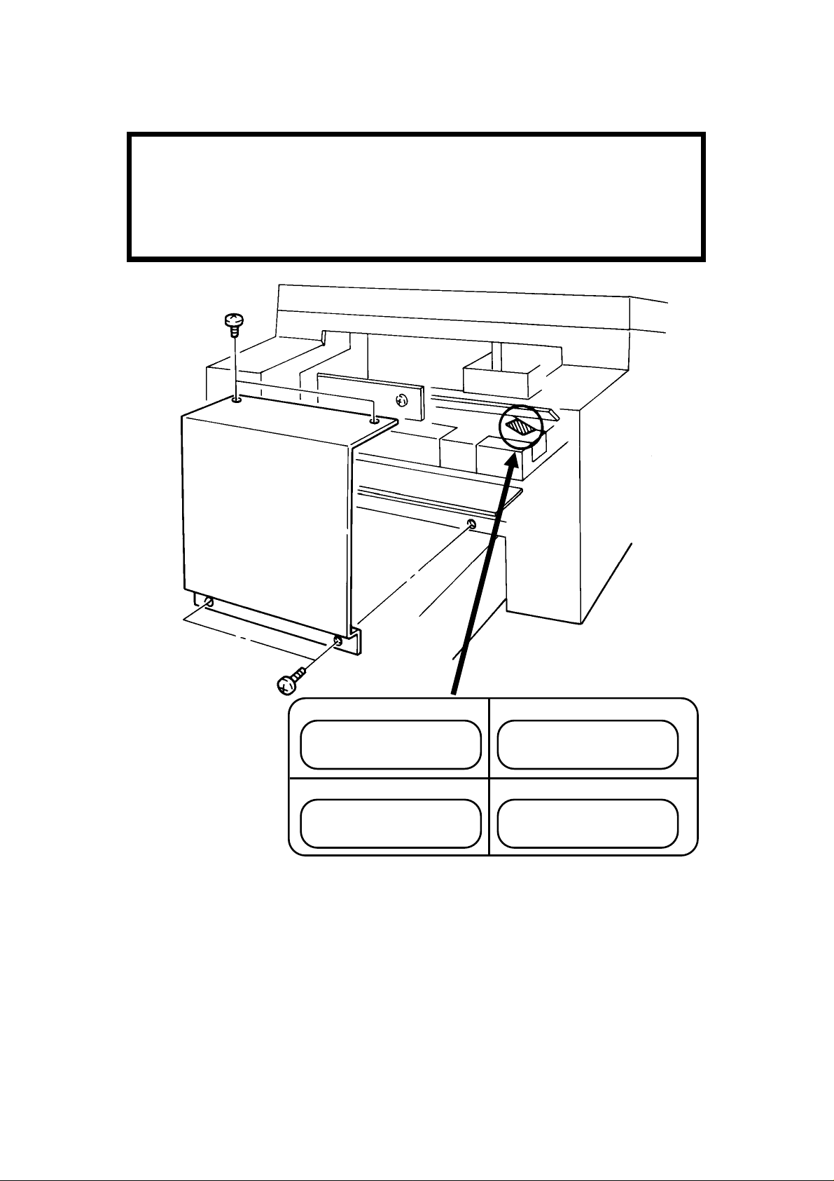
WARNING
DANGER
INVISIBLE LASER RADIATION
WHEN OPEN AVOID DIRECT
EXPOSURE TO BEAM
DANGER
RAYON LASER INVISIBLE
LORS DE L’OUVERTURE
EVITER L’EXPOSITION DIRECTE
VORSICHT
Unsichtbare Laserstrahlung
unter dieser Abdeckung. Nicht
in den laserstrahl blicken.
PELIGRO
RADIACION LASER INVISIBLE
AL ABRIR. EVITAR LA
EXPOSICION DIRECTA AL HAZ
THIS MACHIN E CONTAINS A LASER BEAM GENERATOR. LASER
BEAM S CAN CAUSE PERM ANENT EYE DAM AGE. DO NOT OPEN
THE LASER UNIT O R LOOK ALONG TH E LASER BEAM PATH
WHILE THE M AIN POWER I S ON.
Lithium Batteries (Memory Back-up)
CAUTION:
The danger of explosion exists if a battery of this type is incorrectly replaced.
Replace only with the same or an equivalent type recommended by the
manufacturer. Discard used batteries in accordance with the manufactu rer’s
instructions.
Page 3

OVERALL MACHINE INFORMATION November 11th, 1991
SPECIFICATIONS
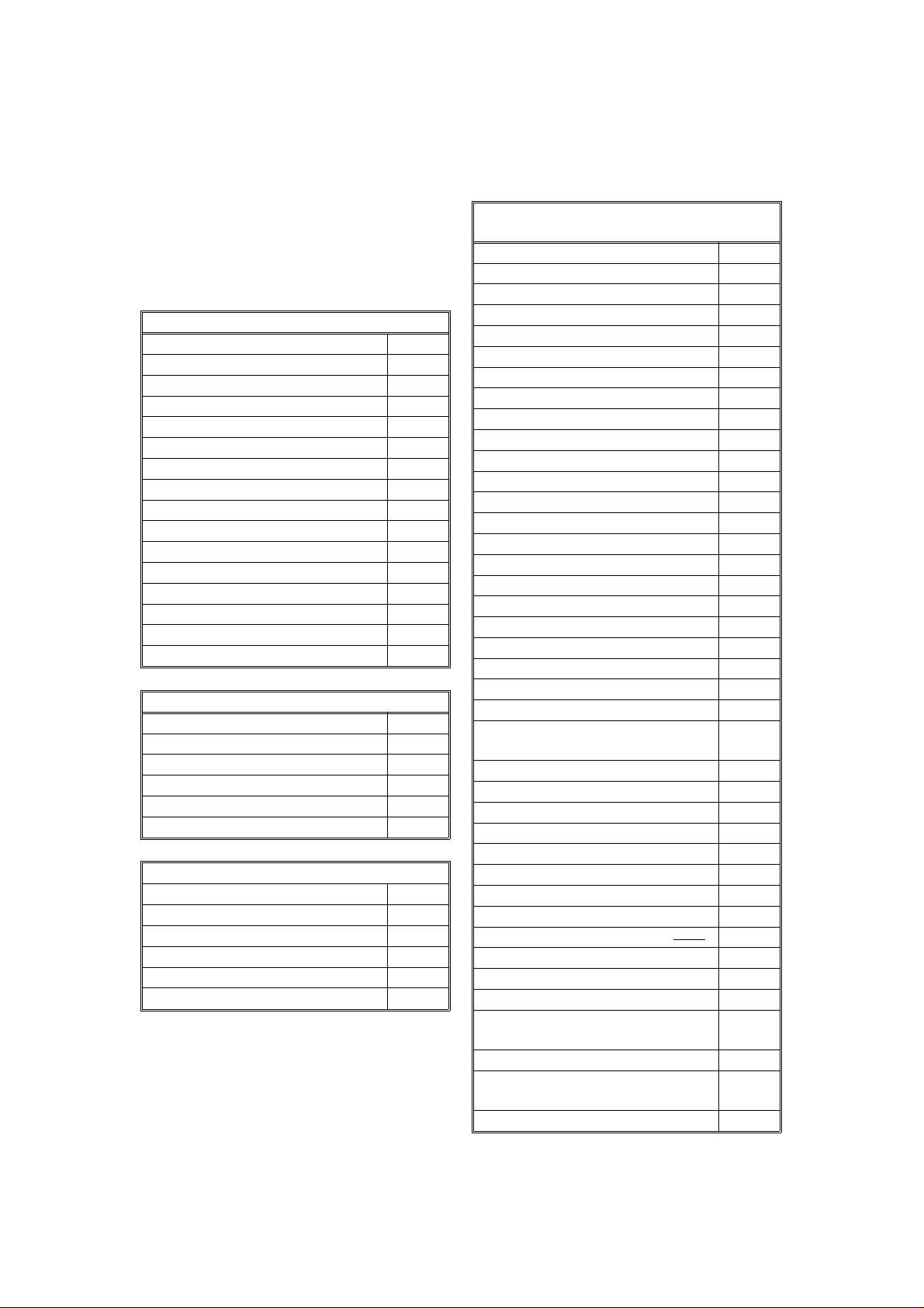
1. OVERALL MACHINE INFORMATION
1.1. SP ECIFICATIONS
Type
Desktop transceiver
Circuit
PSTN, PABX
Connection
Direct couple
Document Size
Length: 105 - 1200 mm
[4.1 - 47.2 ins]
Up to 100 m [328 ft] after adjustment
Width: 148 - 304 mm
[5.8 - 12.0 ins]
Thickness: 0.05 to 0.2 mm
[2 to 8 mils]
Document Feed
Automatic feed, face down
ADF Capacity
50 sheets (using 80 g/m
2
paper)
Data Rate
9600/7200/4800/2400 bps; automatic fallback
I/O Rate
With ECM : 0 ms/line
Without ECM: 5, 1 0, 20, or 40 ms/line
Transmi ssi o n Time
10 s at 9600 bps (G3 ECM using memory)
for a CCITT #1 test document (Slerexe letter) using standard resolution
Printing System
Las er printing, using the Ricoh CS (Compact
Seamless) E ngine, plain paper, dry toner
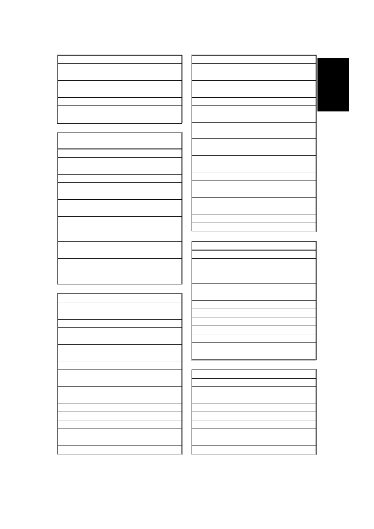
Pap er Size
Standa rd Cassette
Europe: A4, A5
Asia: A4, A5, F, F4
Lower Ca ssette
Europe: A4, A5
Asia: A4, A5, F, F4, B4
1
Scanning Method
Flat bed, with CCD
Maximum Scan Width
256 mm [10.1 ins] ± 1%
Scan Resolution
Main scan: 8 dots/mm [203 dpi]
Sub scan:
Standard - 3.85 lines/mm [98 lpi]
Detail - 7.7 lines /mm [196 lpi]
Fine - 15.4 lines/mm [392 lpi]
Memory Capacity
ECM: 128 kbytes (double buffer)
SAF: Type A - 256 kbytes (14 pages)
Type B - 256 kbytes (14 pages), with
optional extra 1 Mbyte or 2 Mbytes
(max 71 or 128 pages respectively)
Compression
MH, MR, E FC, MMR , SSC
Storage to SAF memory for tx: MH
MMR only with ECM
Modulation
V.29 (QAM), V.27ter (PHM), V.21 (FM)
Maximum Printout Width
210 mm [8.3 ins]
Ma ximu m Printer Resolutio n
Main scan: 16 dots per mm [406 dpi]
Sub scan: 15. 4 lines/mm [392 lpi]
Power Supply
220 - 240 Vac, 50 Hz
Power Consumption (Base Machine Only)
Standby: 35 W
Transmit: 50 W
Receive: 200 W
Copying: 270 W
Operating Environment
Temperature: 17 - 28 °C [63 - 82 °F]
Humidity: 40 - 70 %Rh
Dimensions (W x D x H)
496 x 459 x 293 mm [19.5 x 18.1 x 11.5 ins]
Excluding handset, trays, and optional units
Weight
19 kg [41.8 lbs]
Excluding handset, trays, and optional units
Protocol
Group 3 with ECM
1-1
Page 4
November 11th, 1991 OVERALL MACHINE INFORMATION
FEATURES
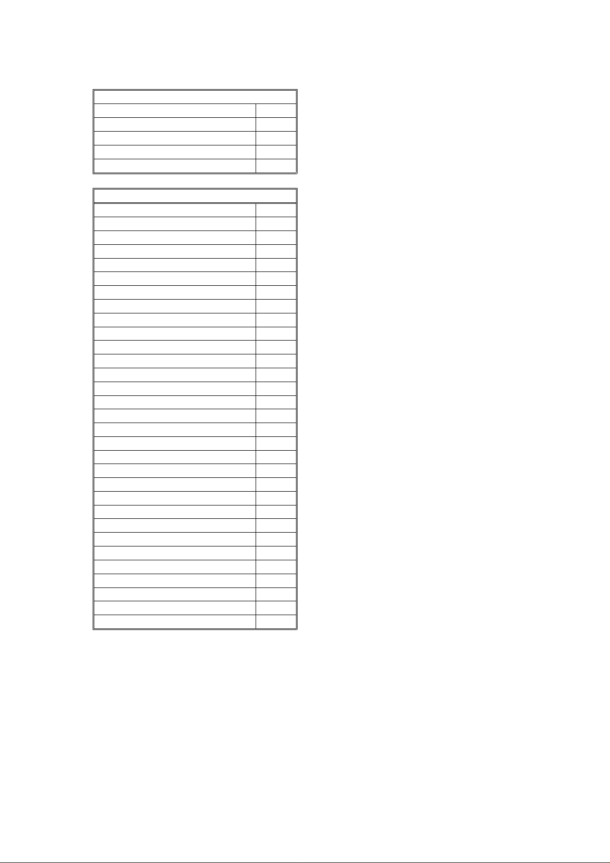
1.2. FEATURES
KEY: O = Used, X = Not Used,
A = Type A with optional me mory only,
B = Type A with lower cassette only,
G = Not used in Germany,
S = Servi ce mode in s ome countries
Equipment
ADF O
Bar code reade r X
Built-in handset X
Cabinet X
Connection for ans. machine X
Connection for handset O
Cutter X
Handset (option only in Europe) O
Hard disk X
Magnetic card reader X
Manual f eed mechanism O
Marker O
Microphone X
Monitor speaker O
R emaining memory indicator O
Speakerphone X
Video Processing Features
Contrast O
Halftone (B asic & Error Dif fusion) O
MTF O
Reduction O
R e s olution O
Smoothing to 16 x 15.4 l/mm O
Communication Features - Auto
Automatic fallback O
Automatic redialling O
Confidential reception A
Dual Acce ss O
Substitute r eception O
Transmission Reserve X
Communication Features -
User Selectable
Action as a transfer broadcaster X
AI Redial O
Alternative Destination O
Answering machine X
Authorize d Reception O
Auto-answer dela y time X
Auto dialling (pulse or DTMF ) O
Auto Docume n t O
Automatic V oice Message X
Auto-note X
Batch Transmission (max 5 files) A
Broadcasting O
Chain Dialling O
Confidential ID O v erride O
Confidential Transmission O
Forwarding (4 stations) A
Fre e Polling O
Gr oups (7 groups) O
Hold X
Immediate Redialling O
Immediate transmission O
Keystr oke Program s O
Mailbox X
Memory transmission (this is the
default mode)
Notify X
On Hook Dia l O (G )
Page C ount O
Per sonal Codes O
Personal Codes with Conf ID O
Polling R eception O
Polling Transmission O
Quick Dial (32 stations) O
Reception mode s (Fax, Tel ,
Reduction O
Remote control features X
Remote Transfer X
Restricted Access (10 codes,
without cards)
Secured Polling O
Secured Polling with Stored ID
Override
Send Later O
Auto) O
O
O
O
1-2
Page 5
OVERALL MACHINE INFORMATION November 11th, 1991
FEATURES
Silent ringing detection X
Speed Dial (100 stations) O
Telephone Di rector y O
Tonal Signal Transmission O
Transfer Request O
Transmission Deadline X
Turnaround Polling X
Voice Request (immed. tx only) O
Communication Features -
Service Selectable
AI Short Protocol X
Auto-reduction override option O
Bus y tone detection O
Closed Ne twork (tx an d rx) O
Continuous Polling Re ception O
Dedicate d t x paramete r s O
ECM O
EFC O
MV1200 compatibility X
Page retransmission O
Page separation m ark O
Polling tx file lifetime in the SAF O
Protection against wrong conn. O
R esol’n stepdown override option X
Short Preamble O
W ell log O
Other User Features
Auto Service Call O
Ce n ter mark O
Chequere d mark X
Clea ring a memory file O
Clea ring a polling file O
Clock O
Confidential ID O
Copy m ode O
Counters O
Di alled n umber che ck X
Direct entry of names O
Function Progr ams O
ID Code O
Label Insertion O
Language Selection O
LCD contrast control S ervic e
Memory L ock A
Memory L ock ID A
Modifying a memory file X
Mu lti So rt Document Rece p t ion A
Multicopy m ode A
Night Timer O
Own t elephone number O
Printing a memory file O
RDS on/off O
R eception Mode S witching T ime r X
Reception Time (non- memory rx
only)
Re mote ID X
R everse Order Printing A
RTI, TTI, CSI O (S)
Speaker volume control O
Specified Cassette S election B
Substitute r eception on/off O
Telephone line type O (S)
TTI on/off O
Use r Function Keys X
User Parameters O
Wild Cards O
Reports - Automatic
Charge Control Report X
Communication Failure Report O
Confidential File Report O
Error Report O
Memory Storage Report O
Mode Chan ge Report X
Polling Clea r Report O
Polling R eserve Report O
Polling R esult Report O
Power Failure Report O
Journal O
Transfer Result Report X
Transmission Result Report O
Reports - User-initiated
Authorized R eception List O
Charge Control Report X
File L is t O
Forwarding List A
Gr oup List O
Per sonal Code List O
Program List O
Quick Dial List O
Specified Cassette Selection List B
O
1
1-3
Page 6
November 11th, 1991 OVERALL MACHINE INFORMATION
FEATURES
Reports - User-initiated
Speed Dial List O
Journal O
Transmission Status Report X
User Function List X
Use r Paramete r List O
Service Mode Features
Back-to-back t est O
Bit switch programming O
Buzzer test O
Cable equalizer (rx only) O
Comm. par ameter display O
DTMF tone test O
Echo countermeasure O
Error code display O
LCD contrast adjustment O
Memory file forwarding O
Memory file printout (all files) O
Modem te st O
NCU parameters O
Operation panel test O
Printer mechanism test X
Printer te st patterns O
Progra mmable atten u ation X
Protocol dum p list O
R AM display/rewrite O
RAM dump O
R inger tes t X
Scanner la mp test O
Scan n er mechanism test O
Sens or initialization X
Serial number O
Service m onitor repor t O
Serv ice s tation numbe r O
Syste m parameter list O
Technical data on the Journal O
T h ermal head parameters X
Transmission Status Report X
Memory Files
Max. number of files: 100
Max. number of stations/file: 142
Max. number of stations overall: 299
Max. number of pages overall: 200
(including pages stored as Auto
Documents)
1-4
Page 7

OVERALL MACHINE INFORMATION November 11th, 1991
COM PONEN T LAYOUT
1.3. COMPONENT LAYOUT
1.3.1. Mechanical Components
1
14
15
16
17
18
19
20
21
22
23
24
13
12
11
10
2
6789
45
3
1
32
31
30
25
26
27
1. R2 Rollers Feed the document through the scanner.
2. Exposure Glass Exposes the original to light from the xenon lamp.
3. R1 Rollers Feed the document through the scanner.
4. Separat ion Roller Allows on e page i nto the scann er.
5. Document Feed Roller Feeds the document into the scanner.
6. Pick -up R oller Picks up pages of the document from the document
table .
7. Toner Cartridge This supplies toner to the development unit. It is part of
the CTM (Cleaning/Toner Magazine).
8. Charge Corona Unit This applies a charge to the master at the start of the
print cycle.
9. Quenching L amp This removes excess charge from the master at the end
of the print cycle.
10. Thermistor This measures the tempera ture in the f using unit.
11 . H ot Roller Hea t from this r oller f uses the toner to the copy paper.
28
29
1-5
Page 8

November 11th, 1991 OVERALL MACHINE INFORMATION
COM PONEN T LAYOUT
12 . H ot Roller Strippers These take the paper off th e hot roller af ter fusing.
13. Copy F eed-out R ollers These feed the paper out of the printer.
14. Pressure Roller (Fusing) This applies pressure to the paper during the fusing
process.
15. Cleaning Unit/Used Toner
Tan k
16. Transfe r C orona Unit This applies a charge to the paper to pull the toner off
17. Master Belt Also known as the CS (Compact Seamless) Engine. The
18. Registration R olle r This carries out the registration process.
19. Registration Sens or This dete cts when pape r is approaching the registra tion
20. Development Roller This roller applies toner to the latent image on the
21. Toner Supply Bar This feeds toner to the development roller.
22. Toner Mixing Bar This stirs up the toner in the development unit, so that it
23. Upper Rel ay Rollers The se fe ed paper from the u pper cassette into th e
24. Lower Relay Rollers These feed paper from the lower cassette into the
25. Lower Paper Feed Roller This feeds paper out of the lower cassette.
26. L owe r Paper Se pa ration
Roller
27. Lowe r Paper Pick-up Roller This picks up the t op sheet of paper from the stack in
28. Upper Paper Feed Rollers T hese pick up the top shee t of paper from th e stack in
29. Focusing Lens This focuses the laser beam onto the master belt.
30. Fθ Lenses These ensure that the thickness of the laser beam is
31. He xagonal Mirror This passes the laser beam across the mas ter belt.
32. CCD (Charge Coupled
Device)
This removes excess toner from the master after image
transfer and stores it. It is part of the CTM
(Cleaning/Toner Magazine).
the master a nd onto the copy paper.
latent image is writte n to this organic photoconductor
belt.
roller .
master belt.
does not collect into lumps.
printer .
printer.
This ensure s that only one shee t of paper at a time
leave s the lower cassette.
the lower cassette and pas ses it to the f eed roller.
the upper cassette a n d fe ed it into the printer.
uniform across the main scan.
This converts the light reflected from the document into
an analog video signal.
1-6
Page 9

567
13
14
15
OVERALL MACHINE INFORMATION November 11th, 1991
COM PONEN T LAYOUT
1.3.2. Drive Components
2
3
4
8
1
18
17
1
9
10
16
19
12
20
11
1-7
Page 10

November 11th, 1991 OVERALL MACHINE INFORMATION
COM PONEN T LAYOUT
1. Tx Motor This stepper motor drives the scanne r.
2. R2 Roller This feeds the original through the s canner.
3. Toner Supply Motor This dc motor drives the toner supply mechanism.
4. R1 Roller This feeds the original through the s canner.
5. Shutter Dri ve Gear This ensures that the shutter moves out of th e
document feed path at the correct time.
6. Toner Supply Gear (C TM) This ensure s the supply of toner from the CTM into the
development unit. It is part of the CTM.
7. Cleaning Brush Drive Gear This drives the cleaning brush in the C TM.
8. Hot Roller This fuses th e toner to the copy paper.
9. Copy Feed-out Roller This feeds printouts out of the machine.
10. Pressure Roller This applies pre ssure t o t he copy paper in t he fusing
unit.
11. Registration Roller Drive
Gear
12. Upper Paper Feed Motor This dr ives the paper feed mech anism in the upper
13. Development Roller Drive
Gear
14. Upper Paper Feed Roller
Drive Gear
15. Master Belt Drive Gear This drives the master belt.
16. Paper Feed Clutch This transfers drive from the upper paper feed motor to
17. Toner Supply Gear
(Development)
18. Ma in M otor This brushless dc motor drives the ma ster belt, fusing
19. Lower Paper Feed Motor This drives the paper feed mechanism in the lower
20. Lower Paper Feed Clutch This transfers drive from the lower paper feed motor to
This drives the registration roller.
cassette.
This drive s the de velopme nt roller.
This drives the upper paper fee d roller.
the uppe r paper feed mechanis m.
This ensure s the collection of toner from the CTM, and
its distribution across the full length of the development
unit.
unit, development unit, and cleaning unit.
cassette.
the lower paper fe ed mechanis m.
1-8
Page 11

16
24
12
OVERALL MACHINE INFORMATION November 11th, 1991
COM PONEN T LAYOUT
1.3.3. Electrical Components
11
10
1
13
9
8
2
3
4
5
6
7
1
34
33
32
37
35
36
31
30
29
28
27
26
14
14
15
15
25
17
18
19
20
21
22
23
1-9
Page 12

November 11th, 1991 OVERALL MACHINE INFORMATION
COM PONEN T LAYOUT
Lower Ca ssette
44
43
42
Name Description No.
PCBs
FCU This board controls the machine. 11
MBU This board contains the system ROM and RAM for storing
system parameters such as bit switch settings and programmed
telephone numbers.
SBU This board contains the CCD. 1
OP- PORT Th is board controls t he operation panel. 37
NCU This board contains relays and switches for interfacing the
machine to the network and the handset.
PSU This board supplies power to the ma chine. 3
LD Unit This board drives the laser diode. 10
PF U T his board controls the lower paper fe ed unit. 4 4
MOTORS
Tx M otor This ste pper motor drives the scanner. 34
Main Motor This dc motor drive s the fusing unit, master belt, dev elopment
roller, and cleaning unit.
Upper Paper
Feed Motor
Lower Paper
Feed Motor
Toner Supply Mo-
tor
Hexagonal Mirror
Motor
Ozone F an This removes ozone-laden air from the vicinity of the master unit,
CLUTCHES
This stepper motor drives the upper paper feed mechanism and
the registra ti on roller.
This stepper motor drives the lower pape r f eed mechanism. 43
This dc motor drives the toner s u pply mechanism. 33
This high-speed dc motor drive s the hexagonal mirror in the
lase r printer optics.
an d filter s out the ozone.
38
39
40
41
12
32
30
26
13
5
1-10
Page 13

OVERALL MACHINE INFORMATION November 11th, 1991
COM PONEN T LAYOUT
Name Description No.
Upper Paper
Feed Clutch
Lower Paper
Feed Clutch
SENSORS
Docum ent Sensor This detects the presence of a document in the feeder. 36
Scan Line Se nsor This detects when a page is approaching the auto sha ding
Document Width
Sensor
Toner Near-end
Sensor
Upper Paper Size
Detector
Upper Paper End
Sensor
Registration Sensor
Paper Feed-out
Sensor
Front Cover
Switch
CT M Sensor This detects when a CTM has been ins ta lled in the machine. 27
Lower Paper Size
Detector
Lower Paper End
Sensor
Lower Paper
Feed Sensor
INT ERLOCK S WITCHES
F ron t Cov er Interlock Switches
OTHERS
Spe aker This allows the user to listen to th e condition of th e telephone
Xenon Lamp This lamp illuminates the document. 35
Xenon Lamp
Driver
Charge Corona
and Quenching
Lamp Unit
Transfer Corona
Unit
Varistor This ensures that the charge given to the master by the charge
Marker This stamps a re d circle on each page that is successf ully f ed
T h i s transfe r s drive from the upper pape r feed motor to the
paper feed roller in the upper cassette.
T h i s transfe r s drive from the lower paper feed motor to the paper
fee d roller in the lower cassette.
position.
This detects when a B4-width [10.1"] document has been placed
in the feeder.
This detects when the toner has almost run out. 17
T h i s de tects th e paper s i ze installed in th e upper cassette. Th e
use r mu st install th e correct actuator.
This detects when the paper in the upper cassette ha s run out. 29
This detects when paper has arrived at the re gis tra tion rollers. 2 1
This detects when the paper has been fe d out of the printer. 24
This detects wheth er the front cove r is open or closed. 23
T h i s de tects th e paper s i ze installed in th e lower cass ette. T h e
use r mu st install th e correct actuator.
This detects when the paper in the lower cas sette has run out. 3 8
This sensor detects the presence of paper at t he lowe r paper
feed roller.
If the front cover is open, these interlock switches interrupt the
+ 5VLD power supply for the laser diode and the + 24VD power
supply f or t he power pack, motors, and oth er componen t s.
line.
This drives the xenon lamp. 2
The charge corona unit charges the ma s te r belt a t the s ta rt of
the print cycle. The quenching lamp re move s excess charge
from the master belt at the end of the print cycle .
This pulls the toner off the maste r and onto the copy paper. 7
corona wire does not exceed -750 Volts.
through the scanner.
28
42
14
16
25
41
39
19,
20
31
18
9
15
1
1-11
Page 14

November 11th, 1991 OVERALL MACHINE INFORMATION
COM PONEN T LAYOUT
Name Description No.
Power Pack This s upplies high voltages to the corona wires and the
developme nt bias terminal.
F using Lamp This fuses the toner to the paper. 6
Thermistor This monitors the te mperature inside the f us ing unit. 8
Thermostat This inte rrupts the ac power supply to the fusing lamp if the
temperature exceeds 400 °C.
Lower Cassette
Indicat or Pane l
T h i s conta i n s indicators to show the sta tu s of th e lower cass ette. 40
22
4
1-12
Page 15

OVERALL MACHINE INFORMATION November 11th, 1991
OVERALL MACHINE CONTROL
1.4. OVERALL MACHINE CONTROL
HandsetLine
1
SBU
(CCD)
Scanner
Sensors
Operation
Panel
NCU
CONTROL SIGNALS
Video Processing
Memory
Video
Processor
Speaker
Modem AFE
CPU
DATA AND ADDRESS BUS
PSU
Port
Scanner and Printer Drive
Components and Sensors
FCU
I/O
RS-232C
Interface
Laser
Interface
Page
Memory
SAF
Memory
ECM
Memory
RAMROM
MBU
Laser Diode Driver
Main Scan Start Detector
Interlock Switch
The cpu on the FCU board controls the machine, as shown in the above
drawing.
There is no modem board in the machine. The cpu pe rforms the digital functions of a modem and carries out digital to analog conversion of facsimile
data. There is a separate analog modem chip, called the Modem AFE, which
does the rest of the modem operations.
1-13
Page 16

November 11th, 1991 OVERALL MACHINE INFORMATION
VIDEO DATA PATH
1.5. VIDEO DATA PATH
1.5.1. Transmis sion
Original
Reference:
Group 3
Facsimile
Manual,
section
1-3-1
Xenon
Lamp
ECM
Memory
Line
Buffer
SAF
Memory
RAM
MBU
FIFO
Video
Processor
The fo llowing diag rams show
the data path for this model.
CCD
Analog Signal
CPU
Modem
(Digital)
MODEM
AFE
FCU
Modem
(Analog)
To the
Network
(via the NCU)
1.5.2. Reception
Reference:
Group 3
Facsimile
Manual,
section
1-3-2
From the
Network
(via the NCU)
Line
Buffer
RAM
MBU
FCU
Memory
SAF
FIFO
Filter
HYBRID IC
Memory
ECM
Page
Memory
Laser Diode
Modem
(Analog)
Modem
(Digital)
CPU
MODEM
AFE
Laser
Interface
Laser Diode
Driver
1-14
Copy Paper
Page 17

OVERALL MACHINE INFORMATION November 11th, 1991
POWER DISTRIBUTI O N
1.6. POWER DISTRIBUTION
1.6.1. Distribution Diagram
Lower Paper Feed Motor
Lower Paper Feed Clutch
+24VD
1
AC Main
Power
Fusing
Lamp
PSU
AC Switching
Circuit
+24V
-12V
+24VS
+24VD
+5V
Scanner
Sensors
+5V
Operation
Panel
+5V
+24VD
Regulator
Regulator
+5V
+24VD
+5V
PFU
- 12V
+24VS
+5V
+5V
+24VS
FCU
- 5V
+12V
Sensors and
Indicators
NCU
FUSING UNIT
Thermistor
+5V
+5V
MBU
SAF Memory
+5V
SBU
+12V
+5V
Printer
Sensors
Front Cover
Interlock Switch
Front Cover
Microswitch
+5VLD
+5VLD
LDDR
Laser Diode
+24VD
Motors, Clutches, Lamps,
Marker, Power Pack
+5V
The laser diode is powered by a special + 5V supply, called + 5VLD.
There are two + 24V po wer supplies:
• + 24VS: This is always on when the main switch is on.
• + 24VD: Th is is interrupted if the front cover interlock switch opens.
There is no + 24VD activation sign al from the cpu to the PSU.
1-15
RS-232C
Interface
Page 18

November 11th, 1991 OVERALL MACHINE INFORMATION
POWER DISTRIBUTI O N
1.6.2. Memory Back-up Circuit
Reference:
Group 3
Facsimile
Manual, section
1-4-3, Cir c ui t
type 1
+5V
Voltage
Detector
+24V
[A]
+5V
Switching
Circuit
Regulator
MBU
RAM
1-11
1-9
Battery
Switch
Battery
Switching
Circuit
FCU
17-11
17-9
Real Time
Clock
CPU
Memory
Monitor
SAF
Memory
Battery
Switch
[B]
Battery
The battery [A] on the MBU backs up the RAM on the MBU, which contains
system parameters. It also backs up the real time clock in the cpu. This battery is not rechargeable. CN1-9 tells the cpu whether back-up power (CN1-
11) comes from the battery or the + 5V power supply.
A rechargeable battery [B] on the FCU board backs up the SAF memory and
the real time clock for 1 hour. While the main power is on, the + 24V supply
recharges the battery.
If there is data in the SAF memory, the rechargeable battery [B] also backs
up the real time clock, to preserve the MBU battery.
1-16
 Loading...