

Page 1

RICOH FAX 2500L
(CRO)
SERVICE MANUAL
Page 2

INFOTEC 3661
(CRO)
SERVICE MANUAL
Page 3

NRG 9650
(CRO)
SERVICE MANUAL
Page 4
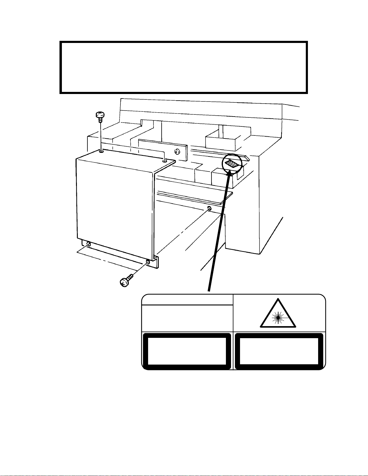
WARNING
THIS MACHINE CONTAINS A LASER BEAM GENERATOR. LASER
BEAMS CAN CAUSE PERMANENT EYE DAMAGE. DO NOT OPEN
THE LASER UNIT OR LOOK ALONG THE LASER BEAM PATH
WHILE THE MAIN POWER IS ON.
DANGER
INVISIBLE LASER RADIATION
WHEN OPEN AVOID DIRECT
EXPOSURE TO BEAM
CAUTION
LASER RADIATION WHEN
OPEN AVOID EXPOSURE
TO BEAM
VORSICHT
UNSICHTBARE LASERSTRAHLUNG,
WENN ABDECKNG GEOFFNET
NICHT DEM STRAHL AUSSETZEN
Lithium Batteries (Memory Back-up)
CAUTION: The danger of explosion exists if a battery of this type is incor-
rectly replaced. Replace only with the same or an equivalent type recommended by the manufacturer. Discard used batteries in accordance with the
manufacturer’s instructions.
Page 5

OVERALL MACHINE INFORMATION June 18th, 1993 SPECIFICATIONS
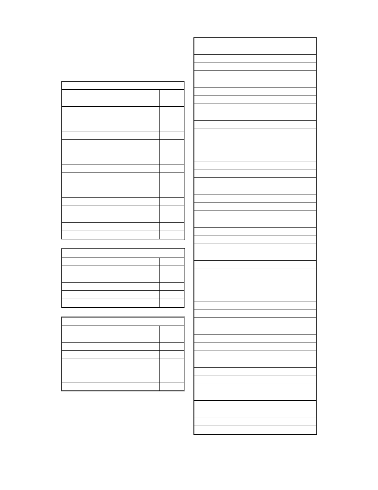
1. OVERALL MACHINE INFORMATION
1.1. SPECIFICATIONS
Type
Desktop transceiver
Circuit
PSTN, PABX
Connection
Direct couple
Document Size
Length: 105 - 1200 mm
[4.1 - 47.2 ins]
Up to 100 m [328 ft] after adjustment
Width: 148 - 304 mm
[5.8 - 12.0 ins]
Thickness: 0.05 to 0.2 mm
[2 to 8 mils]
Document Feed
Automatic feed, face down
ADF Capacity
30 sheets (using 80 g/m
Scanning Method
Flat bed, with CCD
Maximum Scan Width
256 mm [10.1 ins] ± 1%
Scan Resolution
Main scan: 8 dots/mm [203 dpi]
Sub scan:
Standard - 3.85 lines/mm [98 lpi]
Detail - 7.7 lines/mm [196 lpi]
Fine - 15.4 lines/mm [392 lpi]
Memory Capacity
ECM: 128 kbytes (double buffer)
SAF: 128 kbytes (7 pages), with
optional extra 1 Mbyte or 2 Mbytes
(max 64 or 121 pages respectively)
Compression
MH, MR, EFC, MMR, SSC
Storage to SAF memory for tx: MH
MMR only with ECM
2
paper)
Data Rate (bps)
9600/7200/4800/2400
Automatic fallback
I/O Rate
With ECM: 0 ms/line
Without ECM: 5, 10, 20, or 40 ms/line
Transmission Time
10 s at 9600 bps, Measured with G3 ECM
using memory for a CCITT #1 test document
(Slerexe letter) using standard resolution
Printing System
Laser printing, using the Ricoh CS (Compact
Seamless) Engine, plain paper, dry toner
Paper Size
A4, A5
Maximum Printout Width
210 mm [8.3 ins]
Maximum Printer Resolution
Main scan: 16 dots per mm [406 dpi]
Sub scan: 15.4 lines/mm [392 lpi]
Power Supply
220 - 240 Vac, 50 Hz
Power Consumption (Base Machine Only)
Standby: 35 W, Transmit: 50 W
Receive: 200 W, Copying: 270 W
Operating Environment
Temperature: 17 - 28 °C [63 - 82 °F]
Humidity: 40 - 70 %Rh
Dimensions (W x D x H)
496 x 475 x 293 mm [19.5 x 18.7 x 11.5 ins]
Excluding handset, trays, and optional units
Weight
19 kg [41.8 lbs]
Excluding handset, trays, and optional units
Information
Overall Machine
Protocol
Group 3 with ECM
Modulation
V.29 (QAM), V.27ter (PHM), V.21 (FM)
1-1
Page 6
June 18th, 1993 OVERALL MACHINE INFORMATION
FEATURES
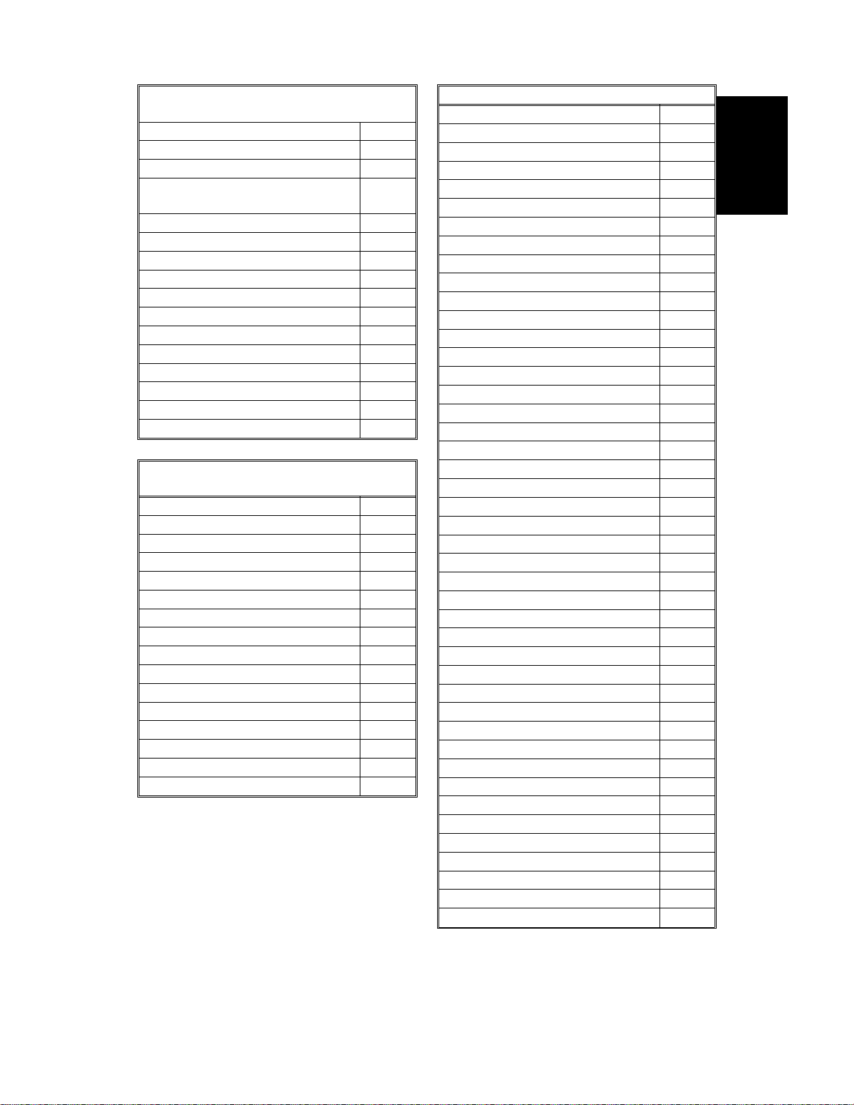
1.2. FEATURES
KEY: O = Used X = Not used,
A = With optional memory only,
B = With printer interface kit only
Equipment
ADF O
Bar code reader X
Built-in handset X
Cabinet X
Connection for ans. machine X
Connection for handset O
Counter (optional) O
Cutter X
Handset (optional) O
Hard disk X
Magnetic card reader X
Manual feed mechanism X
Microphone X
Monitor speaker X
Printer mode (optional) B
Remaining memory indicator O
Speakerphone X
Stamp X
Video Processing Features
Contrast O
Halftone (Basic & Error Diffusion) O
MTF O
Reduction O
Resolution O
Smoothing to 16 x 15.4 l/mm O
Communication Features - Auto
Automatic fallback O
Automatic redialing O
Confidential reception A
Dual Access X
Substitute reception (in Europe
version with standard memory, 1
file only)
Transmission Reserve O
Communication Features -
User Selectable
Action as a transfer broadcaster X
AI Redial (Last one number) O
Alternative Destination O
Answering machine X
Authorized Reception X
Auto-answer delay time X
Auto dialing (pulse or DTMF) O
Auto Document X
Automatic Voice Message X
Auto-note X
Batch Transmission (max 5
batches)
Broadcasting O
Chain Dialing O
Communication Result Display X
Confidential ID Override O
Confidential Transmission O
Direct Fax Number Entry O
Economy Transmission X
Economy Transmission Time X
Forwarding (5 stations) X
Free Polling O
Groups (7 groups) O
Group Transfer Station X
Hold X
ID Transmission Option X
Immediate Redialing O
Immediate transmission (this is
the default mode)
Keystroke Programs O
Mailbox X
Memory transmission O
Multi-step Transfer X
Next Transfer Station X
Notify X
On Hook Dial X
Page Count O
Personal Codes O
O
Personal Codes with Conf. ID O
Polling Reception O
Polling Transmission O
Polling tx file lifetime in the SAF X
Quick Dial (16 stations) O
Reception modes (Fax, Tel) O
Reduction O
Remote control features X
1-2
A
O
Page 7
OVERALL MACHINE INFORMATION June 18th, 1993
FEATURES
Communication Features -
User Selectable
Remote Transfer X
Restricted Access X
Secured Polling O
Secured Polling with Stored ID
Override
Secure Transmission X
Send Later O
Silent ringing detection X
Speed Dial (50 stations) O
Telephone Directory X
Tonal Signal Transmission O
Transfer Request O
Transmission Deadline X
Turnaround Polling X
Two in One X
Two-step Transfer X
Voice Request (immed. tx only) O
Communication Features -
Service Selectable
AI Short Protocol O
Auto-reduction override option O
Busy tone detection O
Closed Network (tx and rx) O
Continuous Polling Reception O
Dedicated tx parameters O
ECM O
EFC O
Inch-mm conversion X
MV1200 compatibility X
Page retransmission O
Page separation mark O
Protection against wrong conn. O
Resol’n stepdown override option X
Short Preamble O
Well log O
Other User Features
Area Code Prefix X
Auto Service Call O
Center mark O
Checkered mark X
O
Clearing a memory file O
Clearing a polling file O
Clock O
Confidential ID O
Copy mode O
Counters O
Country code X
Daylight Saving Time O
Destination Check X
Direct entry of names O
Function Programs O
ID Code O
Label Insertion X
Language Selection O
LCD contrast control Service
Memory Lock A
Memory Lock ID A
Modifying a memory file X
Multi Sort Document Reception X
Multicopy mode O
Night Timer O
OMR Sheet X
Ordering Toner O
Own telephone number O
Printing a memory file O
RDS on/off O
Reception Mode Switching Timer X
Reception Time X
Remote ID X
Reverse Order Printing X
RTI, TTI, CSI O
Secure ID X
Speaker volume control X
Specified Cassette Selection X
Substitute reception on/off O
Telephone line type O
TTI on/off O
User Function Keys X
User Parameters O
Wild Cards X
Information
Overall Machine
1-3
Page 8
June 18th, 1993 OVERALL MACHINE INFORMATION
FEATURES
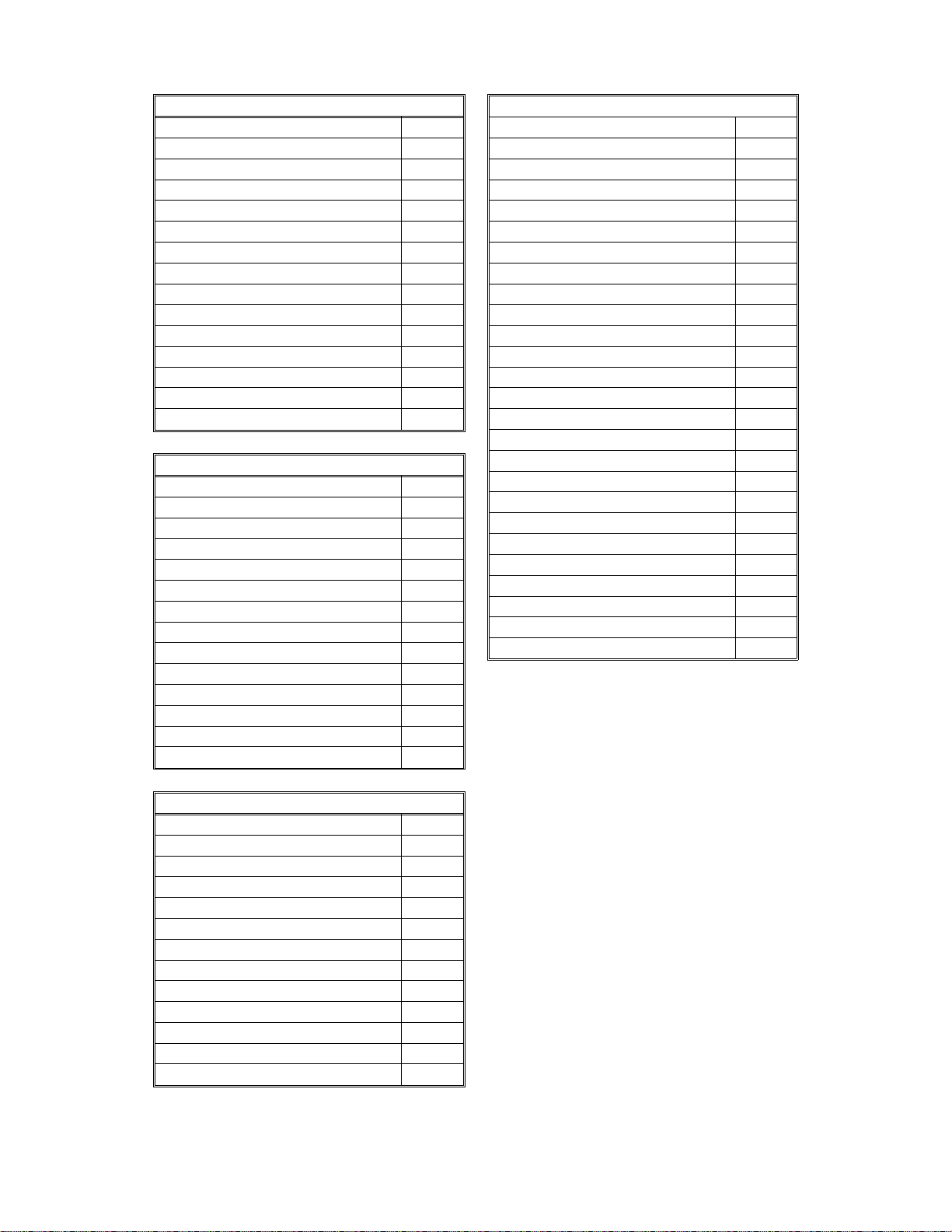
Reports - Automatic
Charge Control Report X
Communication Failure Report O
Confidential File Report A
Error Report O
Memory Storage Report O
Mode Change Report X
Polling Clear Report X
Polling Confirmation List X
Polling Reserve Report O
Polling Result Report O
Power Failure Report O
TCR (Journal) O
Transfer Result Report X
Transmission Deadline Report X
Transmission Result Report O
Reports - User-initiated
Authorized Reception List X
Charge Control Report X
File List O
Forwarding List X
Group List O
Personal Code List O
Program List O
Quick Dial List O
Specified Cassette Selection List X
Speed Dial List O
TCR (Journal) O
Transmission Status Report X
User Function List X
User Parameter List O
Service Mode Features
Back-to-back test O
Bit switch programming O
Buzzer test O
Cable equalizer O
Comm. parameter display O
Counter check X
DTMF tone test O
Echo countermeasure O
Effective term of service calls O
Error code display O
Excessive jam calls O
File Transfer O
Fusing lamp test O
Service Mode Features
LCD contrast adjustment O
Memory file printout (all files) O
Modem test O
NCU parameters O
Operation panel test O
Ozone fan test O
Periodic service call O
PM call O
Printer mechanism test X
Printer test patterns O
Programmable attenuation X
Protocol dump list O
RAM display/rewrite O
RAM dump O
RAM test O
Ringer test X
Scanner lamp test O
Scanner mechanism test O
Sensor initialization X
Serial number O
Service monitor report O
Service station number O
System parameter list O
Technical data on the TCR O
Thermal head parameters X
Transmission Status Report X
Memory Files
Max. number of files: 20
Max. number of stations/file: 20
Max. number of stations overall: 21
Max. number of pages overall: 128
1-4
Page 9
DETAILED SECTION DESCRIPTIONS June 19th, 1993 PCBs AND THEIR FUNCTIONS
2. DETAILED SECTION DESCRIPTIONS
2.1. PCBs AND THEIR FUNCTIONS
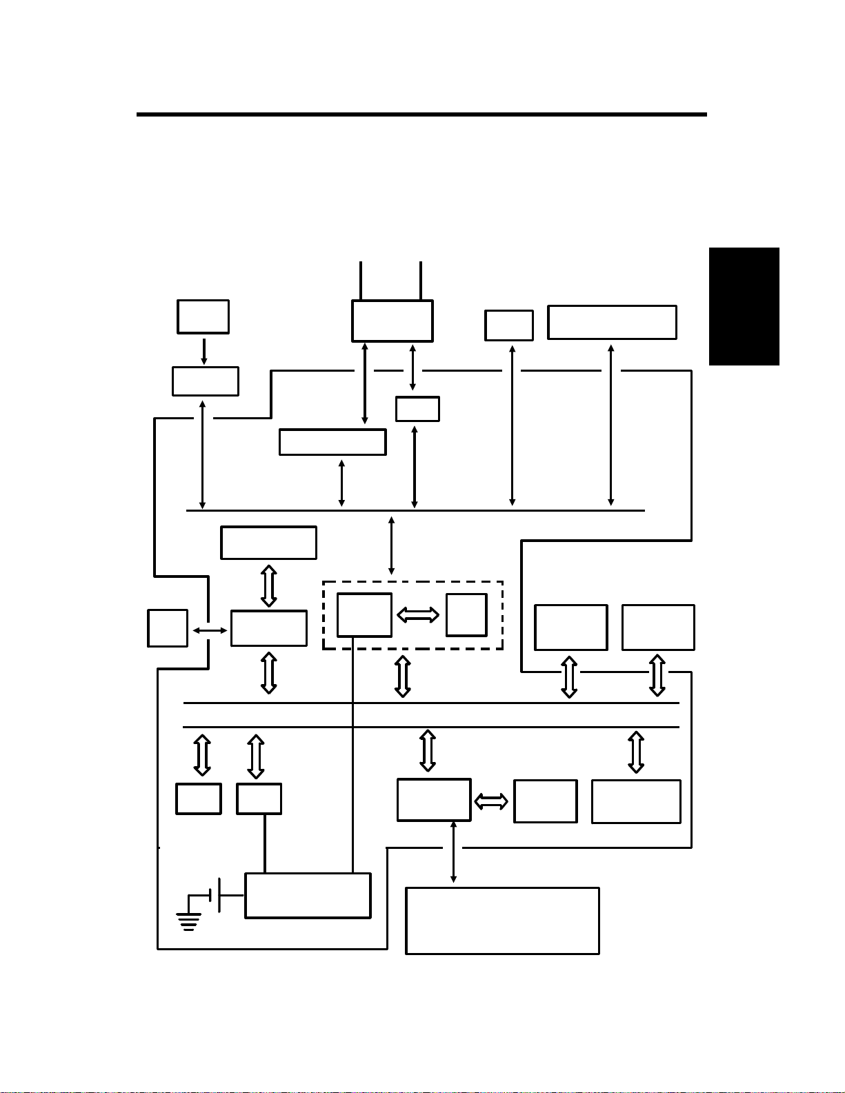
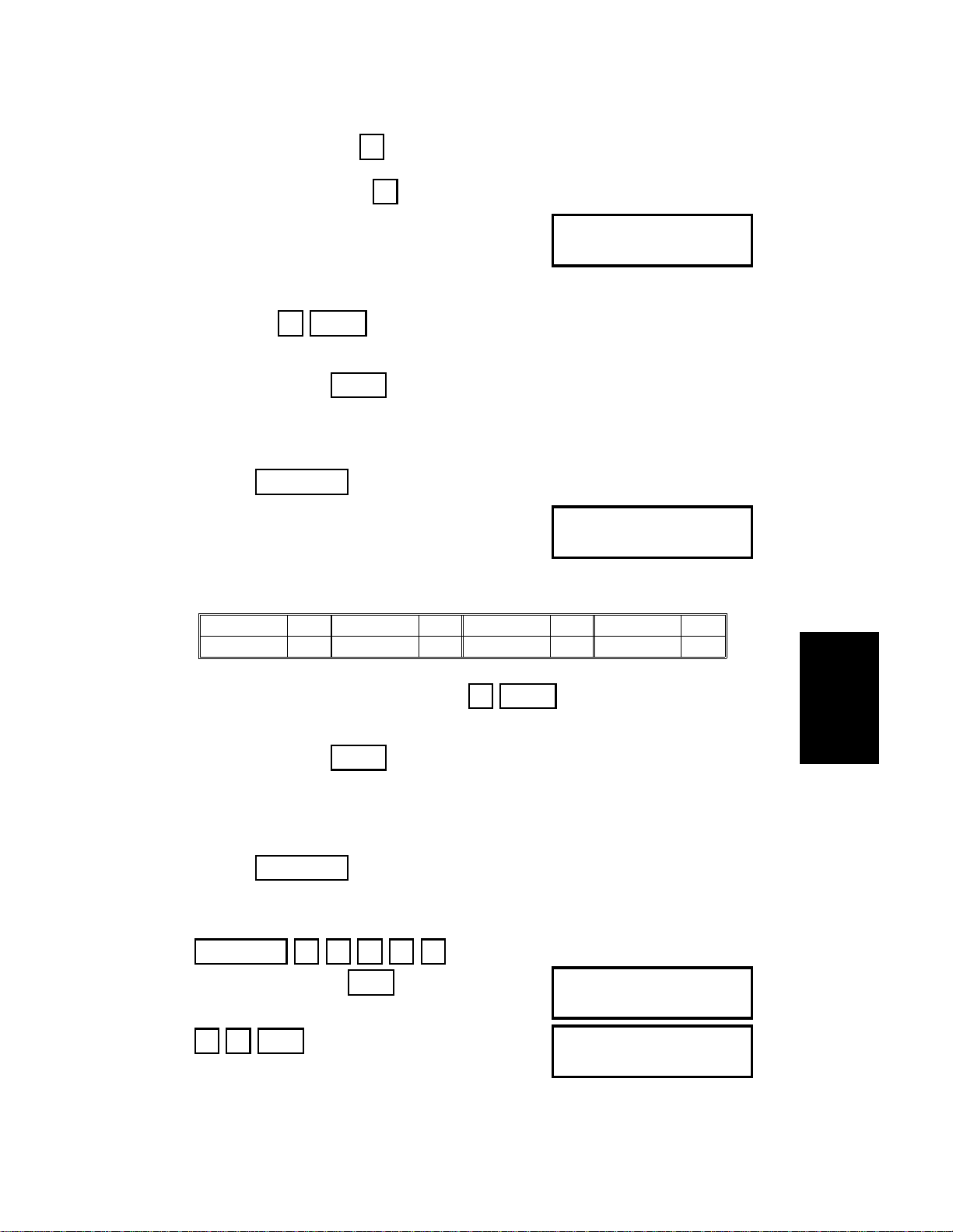
2.1.1. FCU
HandsetLine
SBU
(CCD)
Scanner
Sensors
Operation
Panel
Modem AFE
Video Processing
Memory
Video
Processor
CPU
NCU
HIC
CONTROL SIGNALS
I/O
Port
PSU
Scanner and Printer Drive
Components and Sensors
RS-232C
Interface
Descriptions
Detailed Section
FCU
Printer
Interface
ROM
RAM
+
Memory Back-up
Control
DATA AND ADDRESS BUS
Laser
Interface
Page
Memory
Laser Diode Driver
Main Scan Start Detector
Interlock Switch
2-1
ECM/SAF
Memory
Page 10

June 19th, 1993 DETAILED SECTION DESCRIPTIONS
PCBs AND THEIR FUNCTIONS
1. CPU (AFSP)
65C02 compatible microprocessor
•
• Interrupt and DMA control
•
Data compression and reconstruction (high speed MH coding for 4.5second scanning)
• Modem (digital operations)
• Real time clock (battery backed-up)
•
Memory control
• Control of all mechanisms (directly or through other chips)
• NCU control (through the I/O Port)
2. I/O Port (LIOP)
• Clock control
• Sensor monitoring (including A/D conversion where necessary)
•
Tone detection
• Motor drive
• Operation panel control
• Laser Interface control
3. Laser Interface (ALIF)
• Page memory control
•
Laser diode control
•
Smoothing
• Hexagonal mirror motor control
•
Printer interface control
4. Modem Analog Front End (AFE2)
• Modem (analog operations)
• Attenuation
5. Video Processor (VPP4A)
•
Analog/digital video signal processing
6. Hybrid IC (LHIC)
• Filters
7. RAM
•
256k ECM/SAF memory (no battery back-up)
768k page memory
•
•
32k SRAM and 32k PSRAM for parameter storage, line buffer, FIFO,
SAF memory administration
8. ROM
• 256k system ROM for the machine’s software
2-2
Page 11
INSTALLATION June 19th, 1993
INSTALLING THE MACHINE
3. INSTALLATION
3.1. INSTALLING THE MACHINE
1. Tear off several tapes from
the machine,
and remove the protective
sheet and tabs from the ADF
(Auto Document Feeder) [A].
Make sure that no tape is left
inside the machine,
especially inside the ADF.
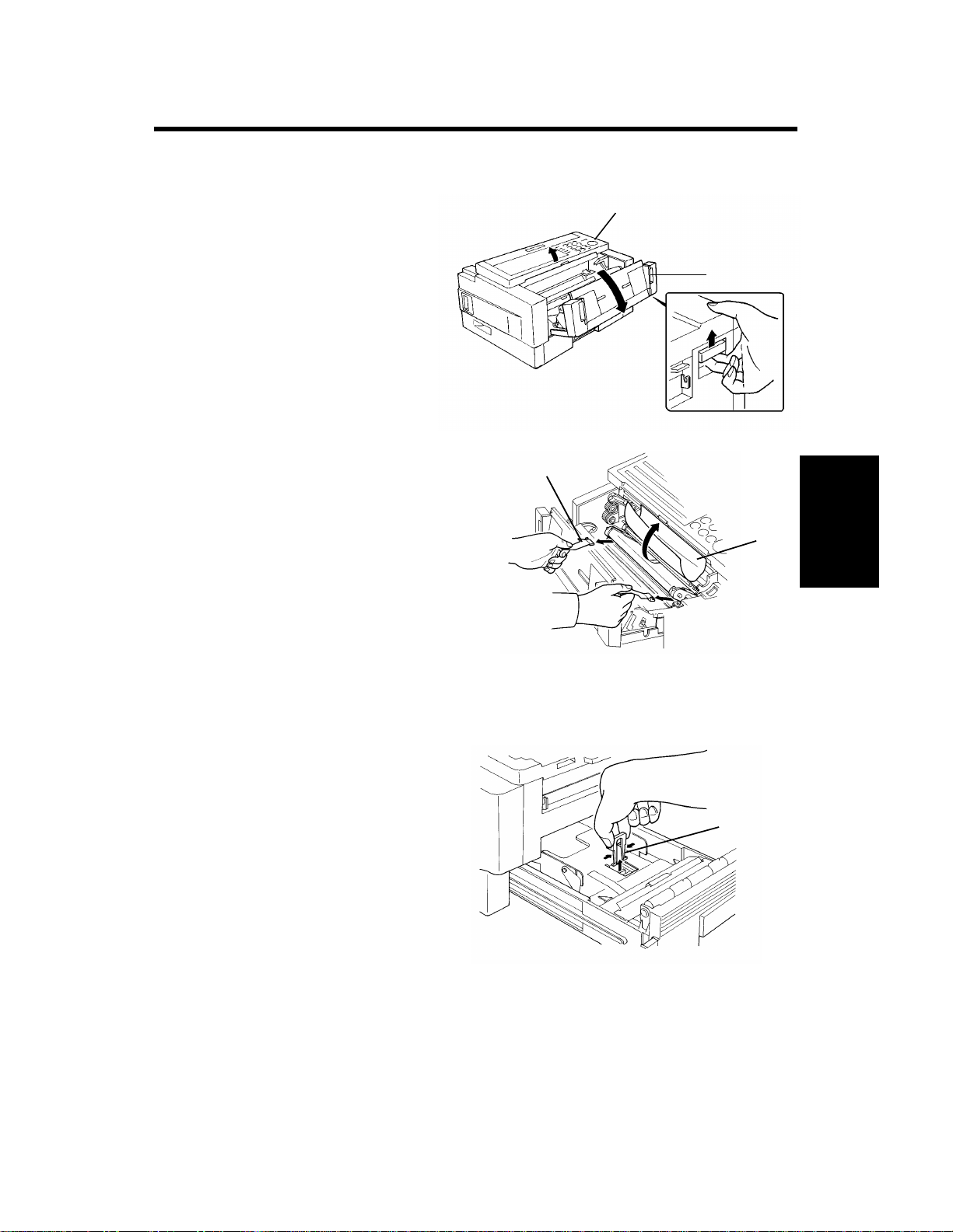
2. Set up the master unit.
Note that the green OPC belt may
be damaged if you
pull out the paper cassette before installing the machine.
[C]
2-1. Make sure that the power
cord is not plugged in.
2-2. Open the scanner [A]
and the front cover [B].
2-3. Pull out the plastic tabs
[C] at both sides of the
master unit.
2-4. Tear off the protective paper [D], being careful
not to touch the green OPC belt.
[A]
[B]
[D]
Installation
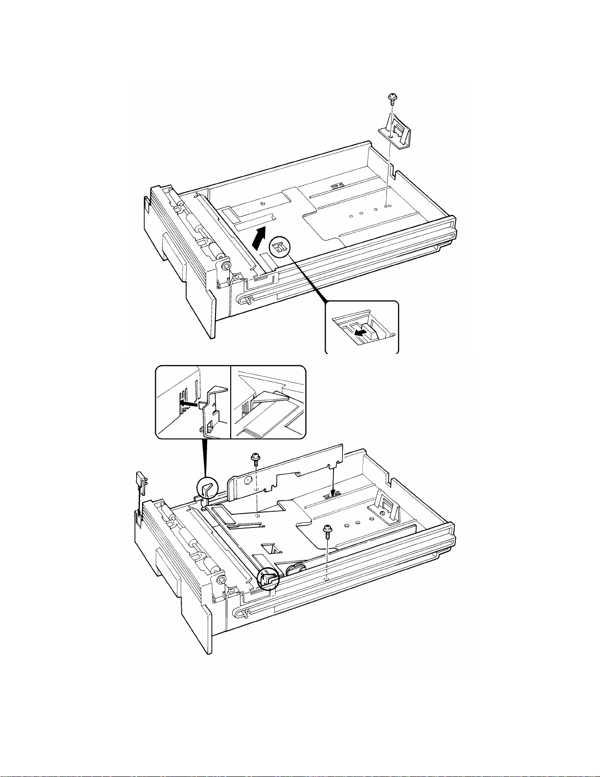
3. Preparing Paper Cassette
3-1. Slide out the cassette.
Then remove the green tab
[E], while holding both sides
of it. Put back the
cassette.
[E]
3-1
Page 12
June 19th, 1993 INSTALLATION
INSTALLING THE MACHINE
4. Install the consumable supplies (paper and toner cassette). Refer to your
operator’s manual (Section 6) for full details.
If necessary, change the paper size of the cassette before loading the paper.
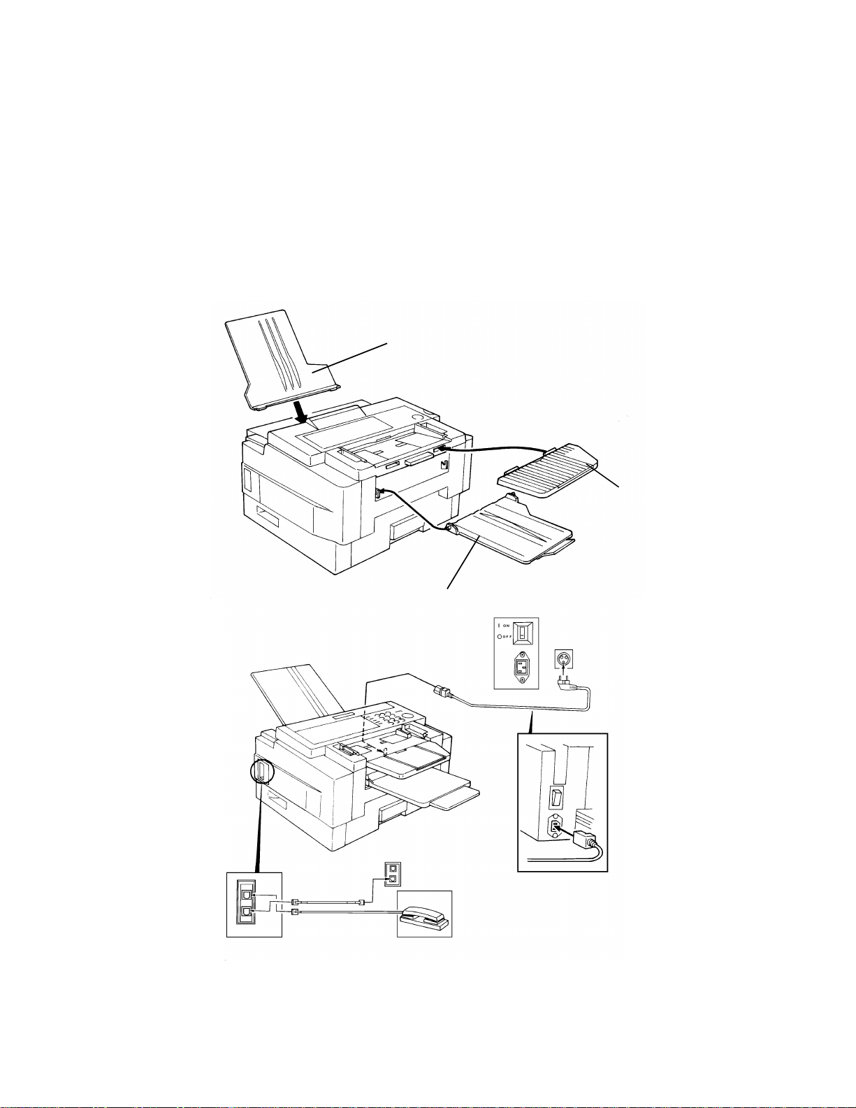
5. Attach the document tray [ I ], copy tray [J], and document table [K] in the
appropriate position.
6. Connect the telephone line and power cord.
If the style of the telephone line is different from the wall socket, contact a
telephone company.
[ I ]
[J]
[K]
7. Turn on the power switch.
3-2
Page 13
INSTALLATION June 19th, 1993
INSTALLING ADDITIONAL UNITS
3.2. INSTALLING ADDITIONAL UNITS
Check whether there are any messages in the memory. If there are, you
must install the lower cassette and turn the power back on within an hour.
3.2.1. Memory Card
• Turn off the power before installing or removing a memory card.
• Make sure that 100% is displayed on the operation panel before install-
ing or removing a memory card, or data will be lost.
Installation
3-3
Page 14
June 19th, 1993 INSTALLATION
INSTALLING ADDITIONAL UNITS
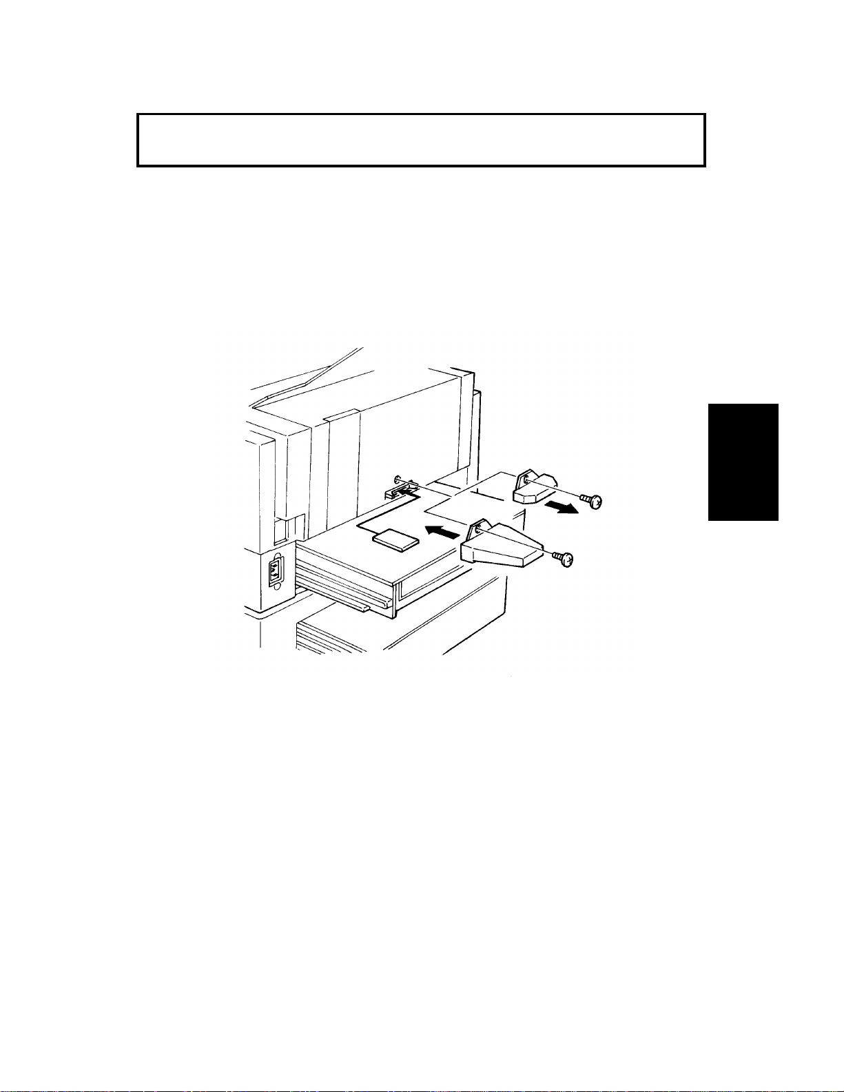
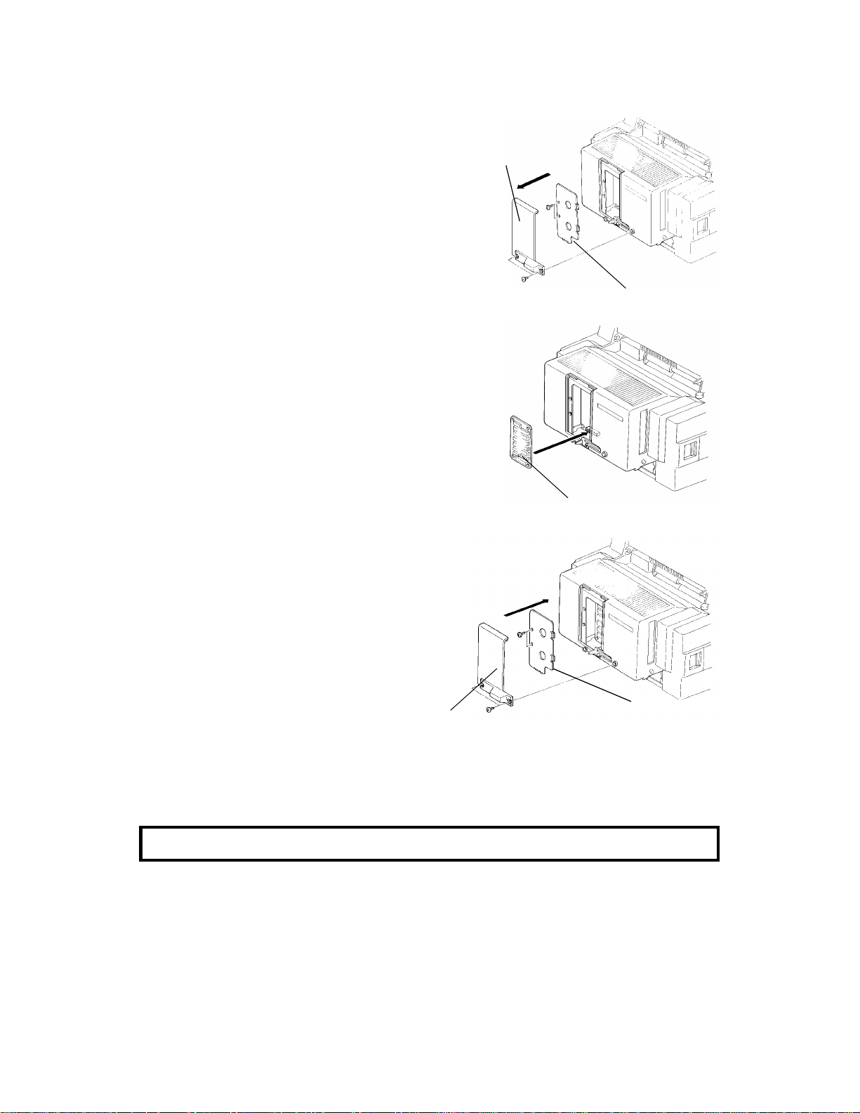
3.2.2. Cassette (250 Sheets)
3-4
Page 15
[B]: 2 screws
INSTALLATION June 19th, 1993
INSTALLING ADDITIONAL UNITS
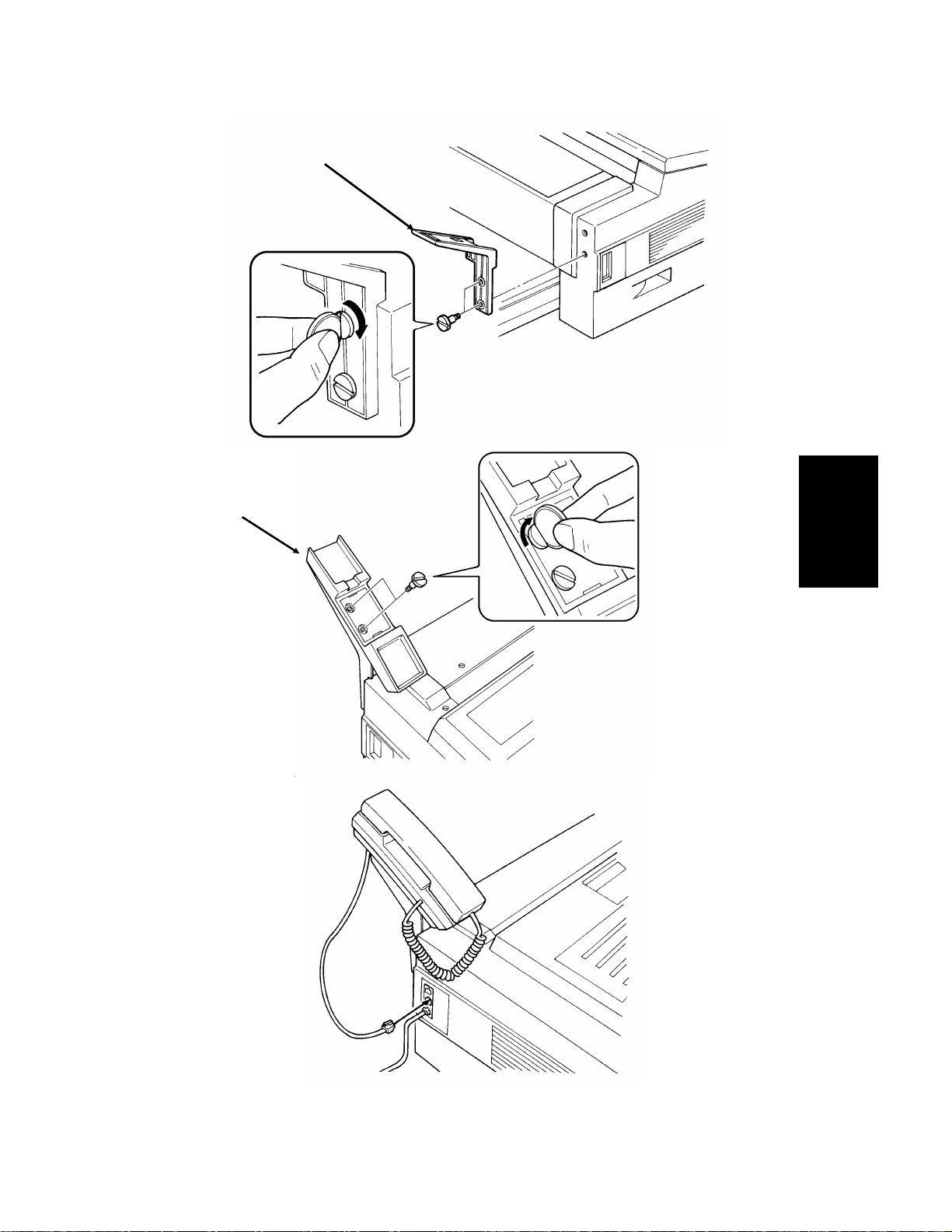
3.2.3. Handset
[A]
[A]: 2 screws
[B]
Installation
3-5
Page 16
June 19th, 1993 INSTALLATION
INSTALLING ADDITIONAL UNITS
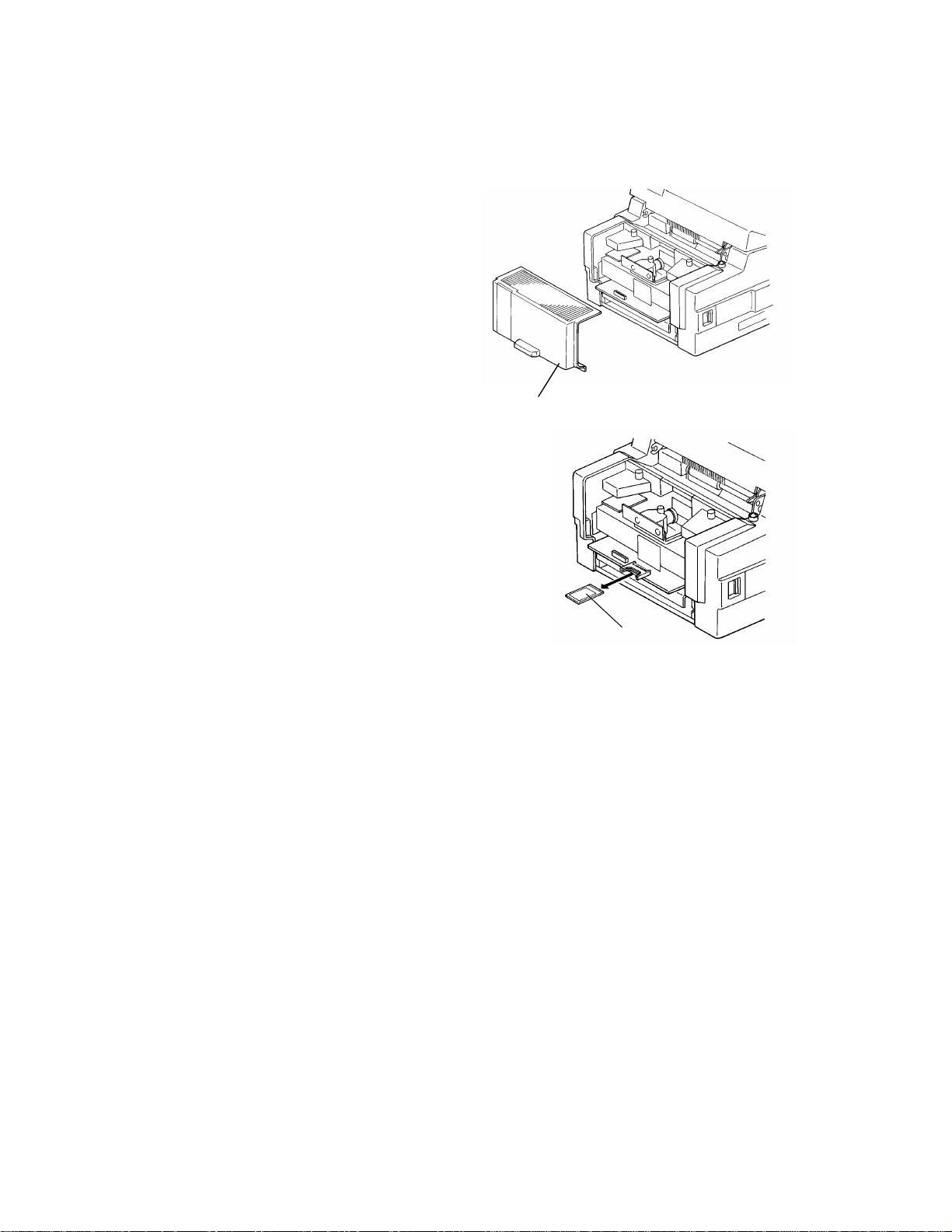
3.2.4. Printer Interface Kit
Installing the Interface Kit
1. First, print any messages still
stored in the SAF.
2. Turn off the power, and unplug the
machine from the wall socket.
3. Slide out the cassettes.
4. Take off the rear cover [A].
[A]
5. If a memory card [C] is installed
on the machine, remove it.
Go to step 8.
[C]
3-6
Page 17
[H]
INSTALLATION June 19th, 1993
INSTALLING ADDITIONAL UNITS
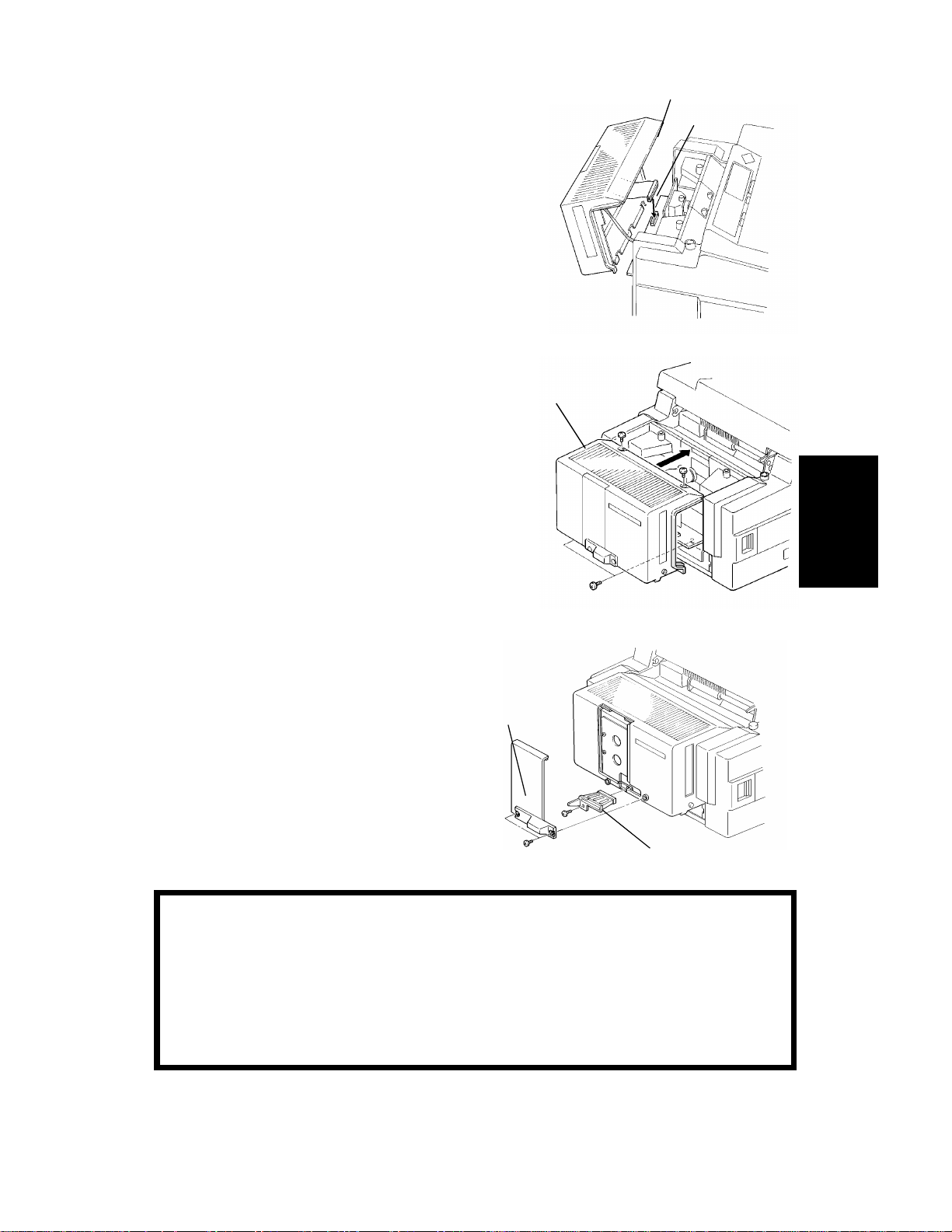
6. Hold the printer interface unit [D] near the
[D]
[ E ]
machine with one hand, and plug the flat
cable [E] into the connecter on the FCU
board.
7. Attach the printer interface unit [F].
[F]
8. Remove the memory option cover [G].
9. Attach the memory card guide [H].
Then install the memory card if necessary.
[G]
10. Put back the option memory cover.
11. Put back the cassettes.
12. Plug in the machine, then turn on the
power.
CAUTION
If an optional memory card is used with the printer interface unit
and you wish to disassemble the machine, be sure to remove the
memory card first, before removing the printer interface unit.
Removing the printer interface unit without removing the memory
card will cause the card or the connector on the FCU to be
physically damaged.
Installation
3-7
Page 18
[N]
June 19th, 1993 INSTALLATION
INSTALLING ADDITIONAL UNITS
Installing the Memory Expansion Board
1. Print any messages still stored in the SAF.
[M]
2. Turn off the power and unplug the machine from the wall socket.
3. Remove the memory option cover [M] and
the memory board cover [N].
4. Insert the memory expansion board [O].
[O]
5. Put back the memory board cover [P]
and the memory option cover [Q].
6. Plug in the machine, then turn on the
power.
[Q]
[P]
Caution: Do not plug in or switch on until everything is connected up.
3-8
Page 19
[A]: 4 screws
[B]: 6 screws
[D]
INSTALLATION June 19th, 1993
INSTALLING ADDITIONAL UNITS
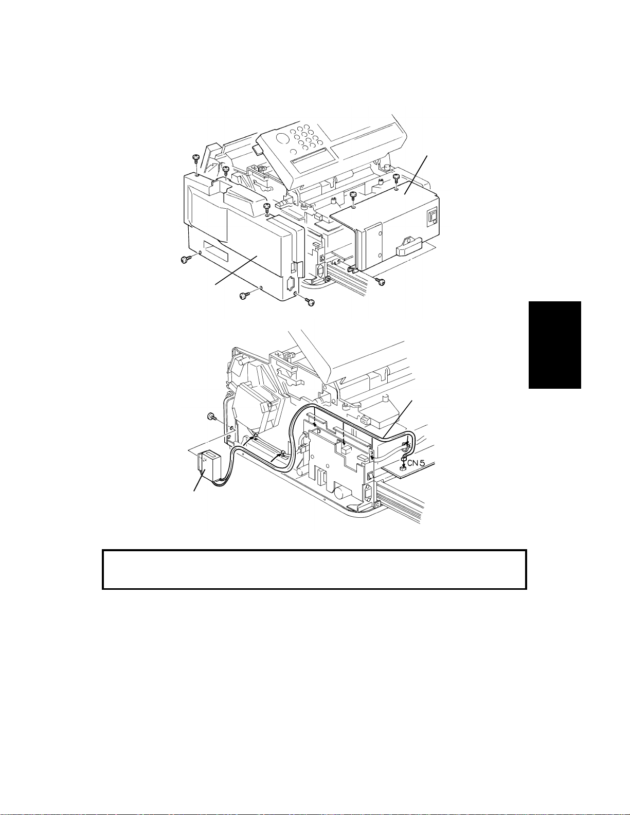
3.2.5. Counter
Turn off the power before beginning this procedure.
[A]
[B]
[C]: 1 screw
[D]: To CN5 on the FCU
[C]
Make sure that the harness is fed through the machine without getting
entangled around components.
Test the counter before reassembling the machine.
1. Carefully turn on the power.
Caution: Do not touch the PSU.
Installation
2. Copy a few sheets.
3. Check that the counter increments correctly.
Then turn off the power, put back the covers, and switch on the machine.
3-9
Page 20

June 19th, 1993 INSTALLATION
INITIAL PROGRAMMING
3.3. INITIAL PROGRAMMING
Check the following:
•
Is the country code in the NCU parameters (Function 96, parameter 00)
correct for the country of installation? In the UK, it should be 02.
• Do any bit switch or other settings have to be changed to match line
conditions or user requirements?
• Have you programmed the serial number (Function 98, section 4-1-19)
The user should program the following items after installation:
• Telephone Line Type (Europe only)
• RTI, TTI, and CSI
• ID Codes (ID Code, Confidential ID, Memory Lock ID)
•
The fax machine’s own telephone number
• Date and Time
• Daylight Saving Time On/Off
• Language Selection
3-10
Page 21
SERVICE TABLES AND PROCEDURES July 14th, 1993 SERVICE LEVEL FUNCTIONS
4. SERVICE TABLES AND PROCEDURES
4.1. SERVICE LEVEL FUNCTIONS
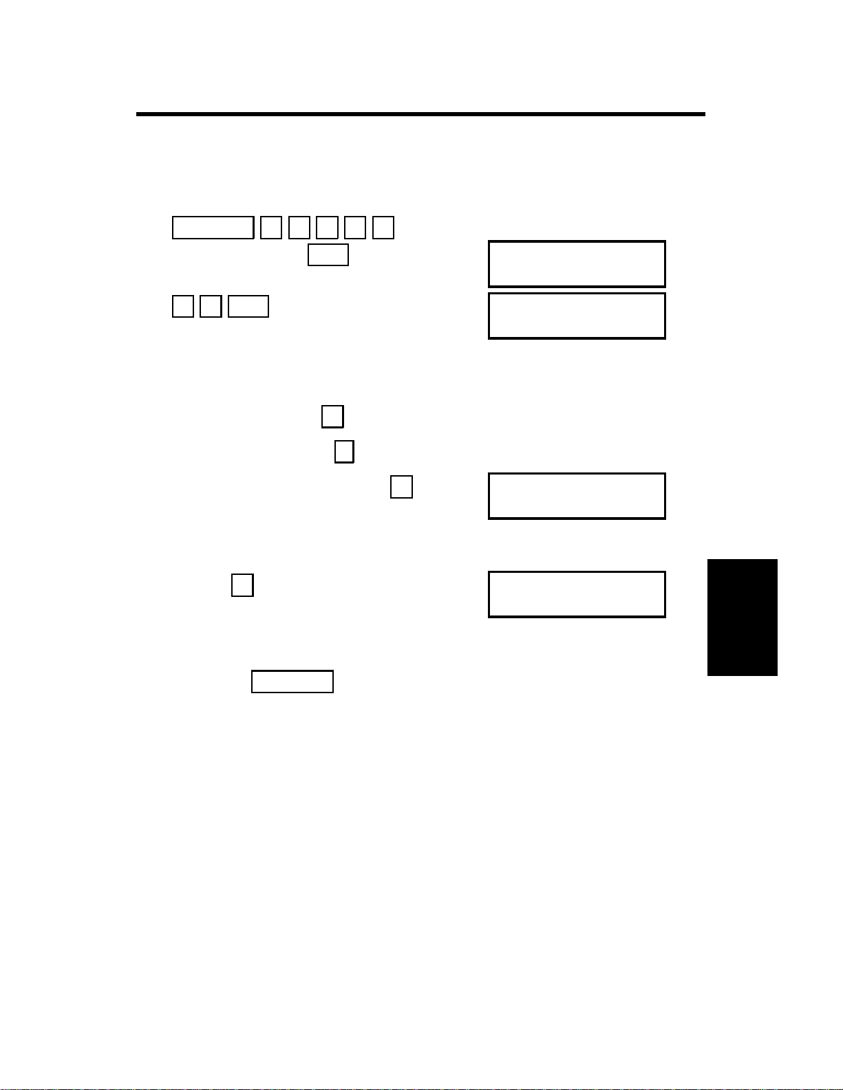
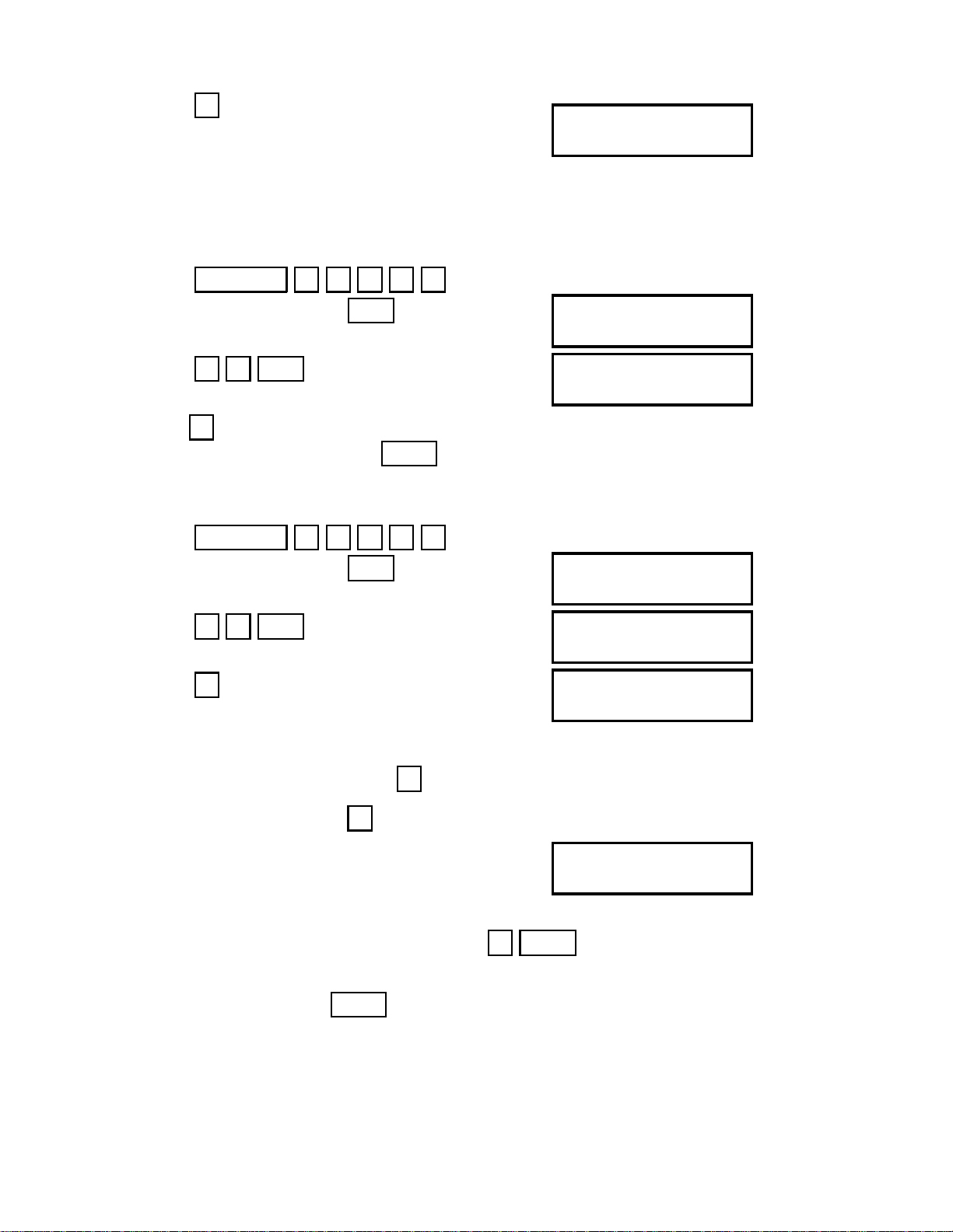
4.1.1. Bit Switch Programming (Function 91)
Function 5 1 9 9 1
1.
then immediately
Yes
2. 9 1 Yes
Bit 7 is displayed at the left, and bit 0 at
the right.
3. Increment bit switch:
Decrement bit switch:
Example: Display bit switch 3:
#
*
# x 3
4. Adjust the bit switch.
Example: To change the value of bit
7, press
7
5. Either:
• Adjust more bit switches - go to step 3.
•
Finish - Function
FUNCTION Y/∇
9 SERVICE FUNCTIONS
DEFAULT: 0000 0000
BITSW 00: 0000 0000
DEFAULT: 0000 0000
BITSW03: 0000 0000
DEFAULT: 0000 0000
BITSW03: 1000 0000
Service Tables
and Procedures
4-1
Page 22
July 14th, 1993 SERVICE TABLES AND PROCEDURES
SERVICE LEVEL FUNCTIONS
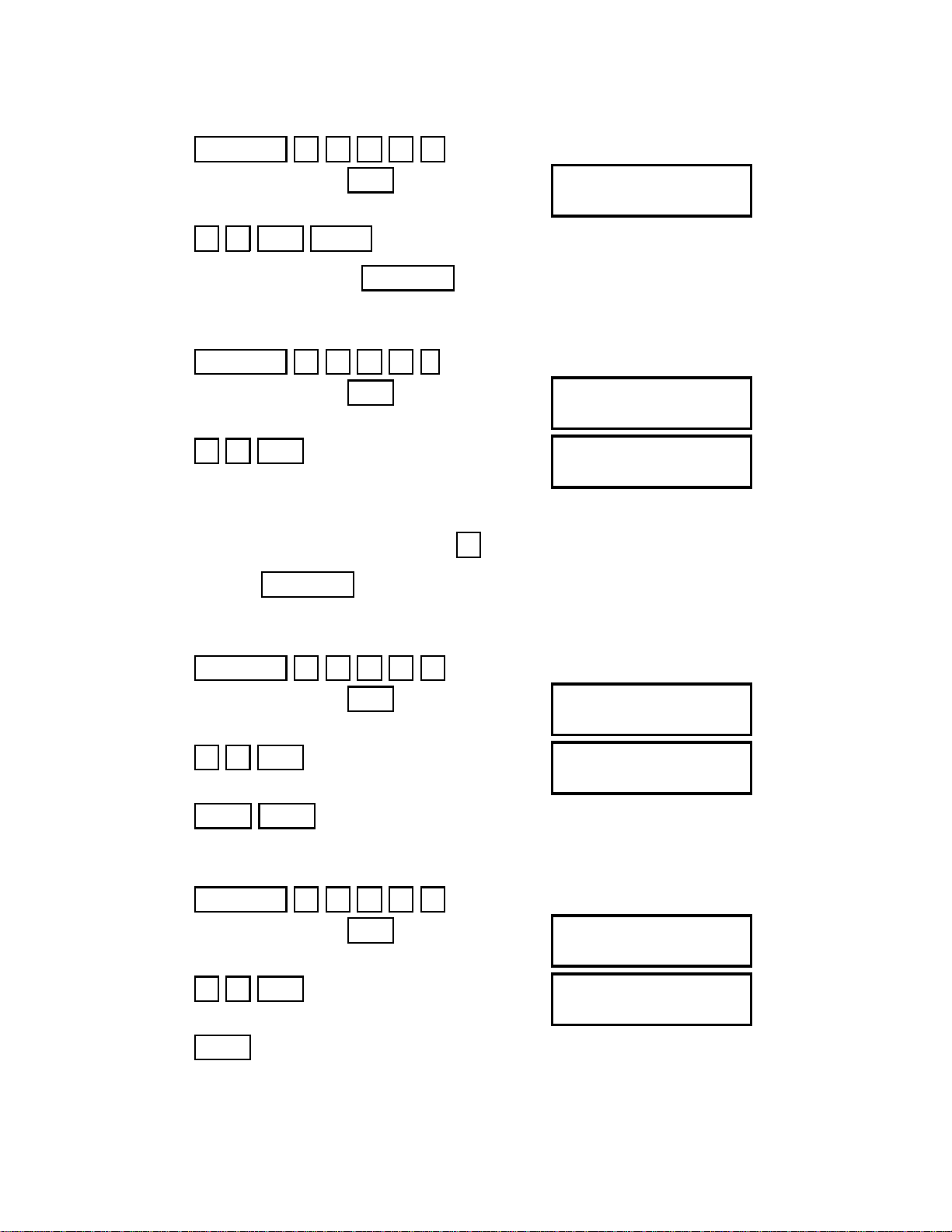
4.1.2. System Parameter List (Function 92)
1.
Function 5 1 9 9 1
then immediately Yes
FUNCTION Y/∇
9 SERVICE FUNCTIONS
2. 9 2 Yes Start
After printing, press
Function
4.1.3. Error Code Display (Function 93)
1. Function 5 1 9 9 1
then immediately Yes
FUNCTION Y/∇
9 SERVICE FUNCTIONS
2. 9 3 Yes ERROR CODE #/∇
1-01 JAN 01 17:30
3. Either:
Scroll through the error codes -
#
Finish - Function
4.1.4. Service Monitor (Function 93)
1.
Function 5 1 9 9 1
then immediately
Yes
2. 9 3 Yes
3. No/∇ Start
4.1.5. Protocol Dump (Function 94)
1. Function 5 1 9 9 1
then immediately Yes
2. 9 4 Yes
3. Start
FUNCTION Y/∇
9 SERVICE FUNCTIONS
ERROR CODE #/∇
1-01 JAN 01 17:30
FUNCTION Y/∇
9 SERVICE FUNCTIONS
START
PROTOCOL DUMP LIST
4-2
Page 23
SERVICE TABLES AND PROCEDURES July 14th, 1993
SERVICE LEVEL FUNCTIONS
4.1.6. RAM Display/Rewrite (Function 95)
1.
Function 5 1 9 9 1
then immediately Yes
FUNCTION Y/∇
9 SERVICE FUNCTIONS
2. 9 5 Yes Y/∇
DISPLAY MEMORY
3. Yes
ADDRESS = 2044C
DATA = 03
4. Input the address that you wish to see. Example: Address 20202
2 0 2 0 2
ADDRESS = 20202
DATA = 00
Note: The first digit must always be 2.
5. If you wish to change the data, type in the new data.
Example: 80, press 8 0 ADDRESS = 20202
DATA = 80
Note: If you wish to move the cursor, press
→
6. Either:
• View more addresses - go to step 4.
• Finish - Yes Function
4.1.7. RAM Dump (Function 95)
1.
Function 5 1 9 9 1
then immediately Yes FUNCTION Y/∇
9 SERVICE FUNCTIONS
2. 9 5 Yes Y/∇
DISPLAY MEMORY
3. ∇ Yes MEMORY DUMP
B=02, S=0000,E=00FF
START/N
4-3
Service Tables
and Procedures
Page 24
July 14th, 1993 SERVICE TABLES AND PROCEDURES
SERVICE LEVEL FUNCTIONS
4. Input the bank number. The value of parameter “B” is always “02”. Then,
input the first two digits of start and end addresses at “S=” and “E=”
prompts. For example, enter “12” for start address 1200(H), and enter 13
for end address 13FF(H). Then, press Start to print the dump list.
Example: Start at 1200, end at 13FF.
0 2 1 2 1 3 Start
MEMORY DUMP START
B=02, S=1200,E=13FF
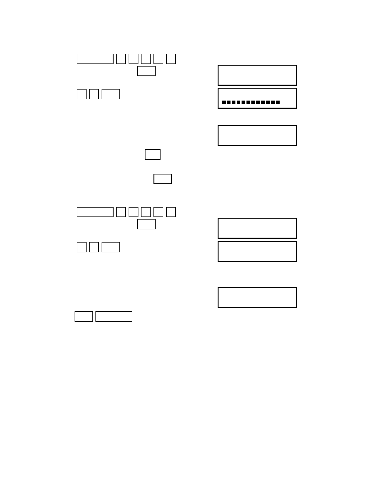
4.1.8.4.1.8. SAF/ECM Memory Test (Function 95)
1. Function 5 1 9 9 1
then immediately
2. 9 5 Yes
Yes
FUNCTION Y/∇
9 SERVICE FUNCTIONS
Y/∇
DISPLAY MEMORY
3. ∇ ∇ Yes . The machine starts to check the DRAMs used as ECM
and SAF memory.
BUSY
CHECK DRAM
4. After the test, either “PASS” or “ERR (Error)” will be displayed.
If “ERR: B=nnH ADR=mmmm” is displayed, replace the FCU (“nn” and
“mmmm” represents the bank number and the address of the defective
portion of the memory.
5. Stop
4.1.9. Page Memory Test (Function 95)
1.
Function 5 1 9 9 1
then immediately Yes
2. 9 5 Yes
4-4
PASS
CHECK DRAM
FUNCTION Y/∇
9 SERVICE FUNCTIONS
Y/∇
DISPLAY MEMORY
Page 25
SERVICE TABLES AND PROCEDURES July 14th, 1993
SERVICE LEVEL FUNCTIONS
3. ∇ ∇ ∇ Yes . The machine starts to check the DRAMs used as
page memory.
BUSY
CHECK PAGE MEMORY
4. After the test, either “PASS” or “ERR (Error)” will be displayed.
If “ERR: B=nnH ADR=mmmm” is displayed, replace the FCU (“nn” and
“mmmm” represents the bank number and the address of the defective
portion of the memory.
PASS
CHECK PAGE MEMORY
5. Stop
4.1.10. NCU Parameters (Function 96)
Function 5 1 9 9 1
1.
then immediately
2. 9 6 Yes
Yes FUNCTION Y/∇
9 SERVICE FUNCTIONS
NCU PARAMETER KPAD/Y
NO.00 017
3. Scroll through the parameters - Yes
Enter new values at the keypad.
Example: Set NCU parameter 04 to 005.
Yes Yes Yes Yes 0 0 5 NCU PARAMETER KPAD/Y
NO.04 005
4. To finish: Function
Note: Parameter 00 is the Country Code, and Parameter 01 is the Tx Level
(if the Tx level should be -9 dB, input 9).
Refer to section 4-3 for full details on NCU parameters.
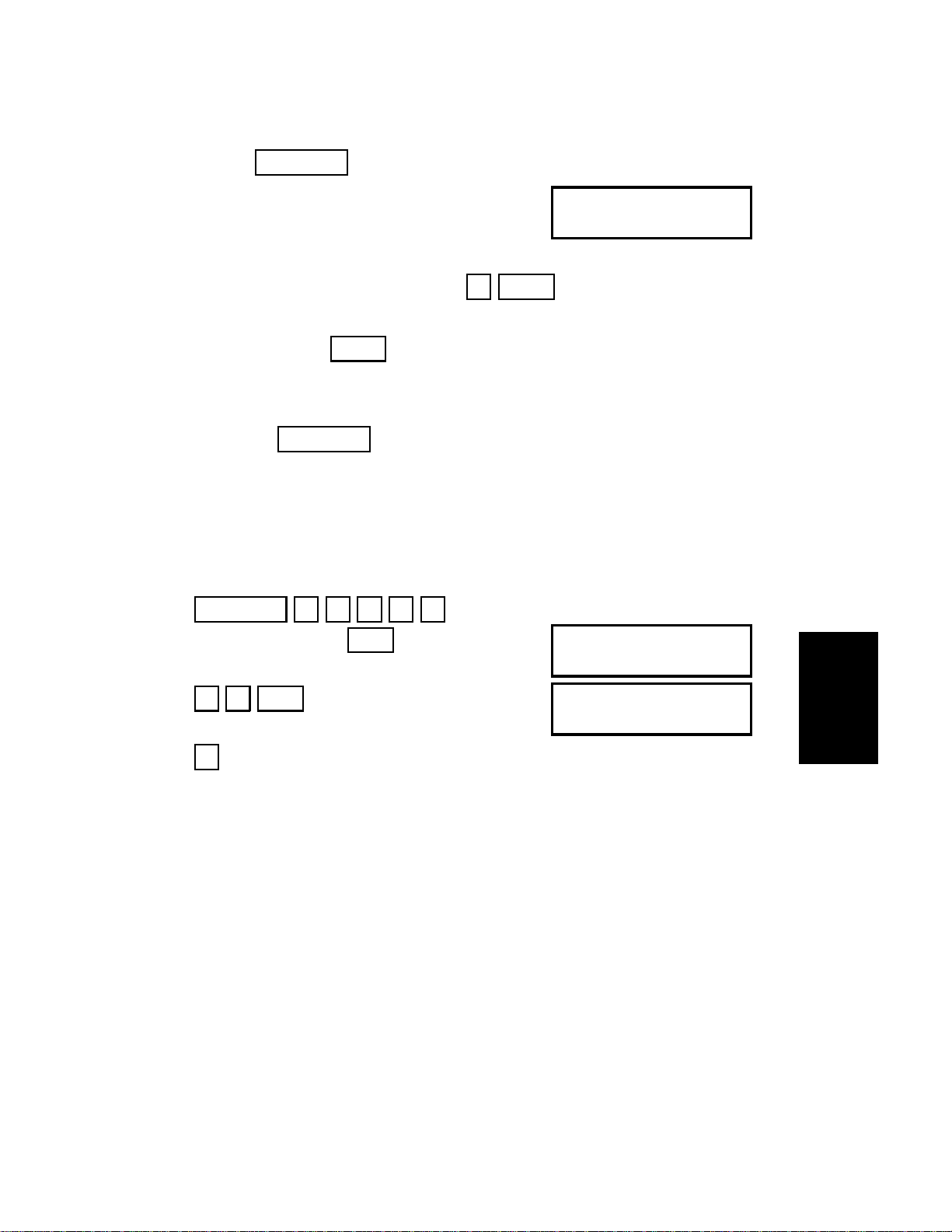
4.1.11. ADF Test (Function 97)
1. Function 5 1 9 9 1
Service Tables
and Procedures
then immediately
Yes FUNCTION Y/∇
9 SERVICE FUNCTIONS
4-5
Page 26
July 14th, 1993 SERVICE TABLES AND PROCEDURES
SERVICE LEVEL FUNCTIONS
2. 9 7 Yes
3. 1
SCN-1 DT-2 PL-3 LD-4
MDM-5 RI-6 CK-7
SCANNER TEST KPAD
ADF-1 LAMP-2
4. 1
5. Function Function
6. Place a document in the feeder,
then press Copy Start
4.1.12. Xenon Lamp and Fusing Lamp Test (Function 97)
Function 5 1 9 9 1
1.
then immediately Yes FUNCTION Y/∇
9 SERVICE FUNCTIONS
2. 9 7 Yes SCN-1 DT-2 PL-3 LD-4
MDM-5 RI-6 CK-7
3. 1 SCANNER TEST KPAD
ADF-1 LAMP-2
4. 2 SCANNER LAMP TEST
The xenon lamp lights up for 5 minutes,
and the fusing lamp is switched on.
4.1.13. DTMF Tone Test (Function 97)
1. Function 5 1 9 9 1
then immediately Yes
2. 9 7 Yes
FUNCTION Y/∇
9 SERVICE FUNCTIONS
SCN-1 DT-2 PL-3 LD-4
MDM-5 RI-6 CK-7
3. 2 DTMF TEST
DUAL-1 SINGLE-2
4-6
Page 27
SERVICE TABLES AND PROCEDURES July 14th, 1993
SERVICE LEVEL FUNCTIONS
4. Either:
• Test dual tones - 1 . Go to step 5.
• Test single tones - 2 . Go to step 8.
5. The display is as shown opposite. DUAL TONE
PRESS KEYPAD
Press a key on the ten key pad.
Example: 1 Start
6. To stop the test:
Stop
7. Either:
Test another tone: Go to step 5.
Finish: Function
8. The display is as shown opposite.
Press the required key.
697 Hz 1 852 Hz 3 1209 Hz 5 1477 Hz 7
770 Hz 2 941 Hz 4 1336 Hz 6 1633 Hz 8
Example: To test 1633 Hz, press 8 Start
9. To stop the test: Stop
10. Either:
Test another tone: Go to step 8.
SINGLE TONE
PRESS KEYPAD
Service Tables
and Procedures
Finish:
Function
4.1.14. Printer Test Patterns (Function 97)
1. Function 5 1 9 9 1
then immediately Yes
2. 9 7 Yes
4-7
FUNCTION Y/∇
9 SERVICE FUNCTIONS
SCN-1 DT-2 PL-3 LD-4
MDM-5 RI-6 CK-7
Page 28
July 14th, 1993 SERVICE TABLES AND PROCEDURES
SERVICE LEVEL FUNCTIONS
3. 3
PATTERN PRINT KPAD
1-7
5. Press a key from 1 to 7, excluding 5 and 6. (Patterns 5 and 6 are not
used in this model.) A test pattern is printed.
4.1.15. Operation Panel and Ozone Fan Test (Function 97)
1.
Function 5 1 9 9 1
then immediately
Yes FUNCTION Y/∇
9 SERVICE FUNCTIONS
2. 9 7 Yes SCN-1 DT-2 PL-3 LD-4
MDM-5 RI-6 CK-7
3. 4
4. To stop the test, press Stop .
4.1.16. Modem Test (Function 97)
1. Function 5 1 9 9 1
then immediately
Yes
2. 9 7 Yes
3. 5
4. Either:
Test G3 carrier signals -
1 . Go to step 5.
Test frequencies - 2 . Go to step 8.
5. The display is as shown opposite.
Press the required key.
Example: Test the 9600 bps carrier
6. To stop the test:
Stop
FUNCTION Y/∇
9 SERVICE FUNCTIONS
SCN-1 DT-2 PL-3 LD-4
MDM-5 RI-6 CK-7
MODEM TEST
G3-1 TONE-2
9600-1 7200-2
4800-3 2400-4 300-5
1 Start
4-8
Page 29
SERVICE TABLES AND PROCEDURES July 14th, 1993
SERVICE LEVEL FUNCTIONS
7. Either:
Test another tone: Go to step 5.
Finish:
Function
8. The display is as shown opposite.
Press the required key.
Example: To test 1100 Hz, press 2 Start
9. To stop the test: Stop
10. Either:
• Test another tone: Go to step 8.
Finish: Function
•
4.1.17. Ringer Test (Function 97)
Not used; do not try to use this function.
4.1.18. Buzzer Test (Function 97)
1. Function 5 1 9 9 1
2100-1 1100-2 800-3
PRESS KEYPAD
then immediately
Yes
2. 9 7 Yes
3. 7
Press the Stop key to stop the buzzer.
FUNCTION Y/∇
9 SERVICE FUNCTIONS
SCN-1 DT-2 PL-3 LD-4
MDM-5 RI-6 CK-7
Service Tables
and Procedures
4-9
Page 30
July 14th, 1993 SERVICE TABLES AND PROCEDURES
SERVICE LEVEL FUNCTIONS
4.1.19. Serial Number (Function 98)
1.
Function 5 1 9 9 1
then immediately Yes
FUNCTION Y/∇
9 SERVICE FUNCTIONS
2. 9 8 Yes SERIAL # KPAD
3. Enter the machine’s serial no at the keypad.
SERIAL # KPAD/Y/N
7940479186
To correct a mistake: No
4. If the display is correct:
Yes
4.1.20. Service Station Telephone Number (Function 99)
Function 5 1 9 9 1
1.
then immediately Yes
2. 9 9 Yes
FUNCTION Y/∇
9 SERVICE FUNCTIONS
TEL NUMBER KEYPAD
3. Input the telephone number of the service station that will receive Auto
Service calls from this machine.
TEL NUMBER KPAD/Y/N
2125555242
4. Yes Function
4-10
Page 31

SERVICE TABLES AND PROCEDURES July 14th, 1993
SERVICE LEVEL FUNCTIONS
4.1.21. Printing all Memory Files (Function 24)
First, set bit 5 of bit switch 01 to 1.
1.
Function 2 4 Yes
FILE NO
2. Press No/∇ Yes Start .
All files in the memory, including confidential messages, will be printed one
by one. The files will not be erased.
After you have finished, set bit 5 of bit switch 01 back to 0.
Note: To erase memory files, set bit 2 of bit switch 00 to 1. All files will be
erased, and some RAM addresses will also be cleared.
4.1.22. CSI Programming
This procedure is for use in countries where CSI programming is a service
function.
First, set bit 5 of bit switch 01 to 1. Then do the following procedure.
Function 5 2 2 2 2
1.
5 3 Yes
Y/∇
SET RTI
2. Press No twice.
3. Press Yes .
4. Input the CSI.
Note: Not more than 20 digits.
Y/∇
SET CSI
CSI KPAD
CSI KPAD/Y/N
2015559456
5. Press Yes Function
After you have finished, set bit 5 of bit switch 01 back to 0.
4-11
Service Tables
and Procedures
Page 32

July 14th, 1993 SERVICE TABLES AND PROCEDURES
SERVICE LEVEL FUNCTIONS
4.1.23. Telephone Line Type Selection
This procedure is for use in countries where telephone line type selection is a
service function.
First, set bit 5 of bit switch 01 to 1. Then do the following procedure.
1.
Function 5 2 2 2 2
7 1 Yes
2. Press Yes .
Y/∇
SELECT TT/DP
LINE = TT Y
TT=1 DP=2
3. Either:
Select tone dialing -
Select pulse dialing -
1 .
2 .
Finish: Function
After you have finished, set bit 5 of bit switch 01 back to 0.
4-12
Page 33

SERVICE TABLES AND PROCEDURES July 14th, 1993
BIT SWITCHES
4.2. BIT SWITCHES
4.2.1. Definitions
WARNING
Do not adjust a bit switch that is described as "Not used", as this
may cause the machine to malfunction or to operate in a manner
that is not accepted by local regulations. Such bits are for use only
in other areas, such as Japan.
Bit Switch 00
FUNCTION COMMENTS
MTF process
0
0: Enabled 1: Disabled
RAM reset level 2
1: Reset
1
RAM reset level 3
1: Reset
Note: RAM reset level
2
1 is a RAM
adjustment. It is not
described in this
manual.
Memory file forwarding
1: Forward the files
3
Inclusion of technical
data on the Journal
0: No 1: Yes
4
5,6 Not used Do not change the factory settings.
Communication
parameter display
7
0: Disabled
1: Enabled
0: The MTF process is used when required by the software.
1: The MTF process is never used.
When this bit is set to 1, all items stored in the RAM are
reset except the clock, and then this bit changes back to 0
automatically. Also, all image files in the SAF memory are
erased.
When this bit is set to 1, some items stored in the RAM are
reset, then this bit changes back to 0. All items are reset
except the bit switch and NCU parameter settings, clock,
own tel. no., CSI, RTI, TTI, Quick Dials, Speed Dials,
Groups, and the TCR memory. Also, all image files in the
SAF memory are erased.
This bit switch is recommended for use when it is necessary
to clear the SAF, as fewer RAMs will need reprogramming.
Use this if the printer does not work, but the user wishes to
print the files. First, change the fax machine’s telephone
number (Function 51) to the number to which you wish to
forward the files, then set this bit to 1. All files in the memory
will be forwarded. This bit resets to 0 automatically.
However, you must return the fax machine’s telephone
number to the original setting. The files stay in memory.
1: Instead of the personal code, the following data are listed
on the TCR as a six-figure number.
First two numbers: Final modem rate (for example, 96
means 9,600 bps)
Second two numbers (Rx mode only): Rx signal level (Level
= 0 - 0.375x, where x is the value on the report; accurate to
3 dB)
Third two numbers (Rx mode only): Rx cable equalizer; 00 =
Equalizer is Off, 01 = Equalizer is On
This is a fault-finding aid. The LCD shows the key
parameters (see below). This is normally disabled because
it cancels the CSI display for the user.
Make sure that you reset this bit after testing.
Service Tables
and Procedures
4-13
Page 34

July 14th, 1993 SERVICE TABLES AND PROCEDURES
BIT SWITCHES
Communication parameter display
Mode DCS: CCITT G3
NSS: Non-standard G3
Modem rate 96: 9600 bps
72: 7200 bps
48: 4800 bps
24: 2400 bps
Communication
mode
Compression
mode
Resolution SSF: Fine, transmitted at 8 x 15.4 dots per mm
I/O Rate 0M: 0 ms/line
Width and
reduction
ECM: With ECM
SSC: Using SSC
EFC: Using EFC
NML: With no ECM, SSC, or EFC
MMR: MMR compression
MR: MR compression
MH: MH compression
PSF: Fine, transmitted at 8 x 7.7 dots per mm and smoothed at the rx
side
DTL: Detail
STD: Standard
2/M: 2.5 ms/line
5M: 5 ms/line
10M: 10 ms/line
20M: 20 ms/line
40M: 40 ms/line
=A4: A4 (8.3"), no reduction
>A4: Reduced to A4 (8.3") before transmission
4-14
Page 35

SERVICE TABLES AND PROCEDURES July 14th, 1993
BIT SWITCHES
Bit Switch 01
FUNCTION COMMENTS
LCD contrast
Bit 1 0 Contrast
0
0 0 Brightest
0 1 ↓
1
1 0 ↓
1 1 Darkest
2 Not used Do not change the factory setting.
Memory read/write by RDS
Bit 4 3 Setting
0 0 Always enabled
0 1 User selectable
1 0 User selectable
3
1 1 Always disabled
4
Dedicated transmission parameter
programming/printing all SAF files
0: Disabled 1: Enabled
5
6 Not used Do not change the factory setting.
Auto Service Call for PM
0: Enabled 1: Disabled
7
Use these bit switches to adjust the brightness
of the LCD on the operation panel.
(0,0): At any time, an RDS system can read or
write RAM data such as TTI and bit switches.
(0,1), (1,0): Normally, RDS systems are locked
out, but the user can temporarily switch RDS
on to allow an RDS operation to take place.
RDS will automatically switch off again after a
certain time, which is stored in a RAM address
(see section 4-5). Note that, if an RDS
operation takes place, RDS will not switch off
until this time limit has expired.
(1,1): All RDS systems are always locked out.
This bit must be set to 1 before attempting to
program dedicated transmission parameters or
printing all files stored in the SAF memory. If
CSI and /or telephone line type is a service
mode in your area, this bit must also be at 1
before programming.
0: The machine will send an Auto Service Call
when the PM interval has expired. This interval
is adjustable by RAM address. The default
setting is every 30,000 copies (based on the
Print counter).
1: The user will do maintenance as explained
in the Operator’s Manual whenever problems
occur.
Service Tables
and Procedures
4-15
Page 36

July 14th, 1993 SERVICE TABLES AND PROCEDURES
BIT SWITCHES
Bit Switch 02
FUNCTION COMMENTS
Page separation mark
0: Enabled 1: Disabled
0
Repetition of data when the
received page is longer than the
1
printer paper
0: Disabled 1: Enabled
Reduction of the length of
received data
2
0: Enabled 1: Disabled
3 Not used Do not change the factory settings.
4
5
Maximum transmittable document
length
Bit 7 6 Setting
6
0 0 600 mm
0 1 1200 mm
7
1 0 14 m
1 1 100 m
0: If a received page has to be printed out on two
sheets, an "x" inside a small box is printed at the
bottom right hand corner of the first sheet, and a
"2" inside a small box is printed at the top right
hand corner of the second sheet. This helps the
user to identify pages that have been split up.
1: No marks are printed.
0: The next page continues from where the
previous page left off
1: The final few mm of the previous page are
printed at the top of the next page.
This bit determines whether incoming pages are
reduced to fit on the copy paper if they are
almost the same length as the copy paper in the
cassette.
If the user wants to send very long documents
such as well logs, use the 14 m or 100 m setting.
4-16
Page 37

SERVICE TABLES AND PROCEDURES July 14th, 1993
BIT SWITCHES
Bit Switch 03
FUNCTION COMMENTS
Dialing with the handset off-hook
0
0: Enabled
1: Disabled
Lifetime of polling standby files in
the memory
1
0: Erased after being polled
1: Kept until user erases
Inclusion of communications on
the TCR when no image data was
2
exchanged.
0: No 1: Yes
Printing of the error code on the
3
error report
0: No 1: Yes
4 Not used Do not change the factory setting.
Printing the TTI in copy mode
5
0: No 1: Yes
6 Not used Do not change the factory setting.
Reconstruction time for the first
line in receive mode
0: 6 s 1: 10 s
7
If this bit is 1, the user will not be able to dial if
the handset is off hook.
0: Messages stored for polling transmission will
be erased immediately after polling.
1: This setting allows the user to keep messages
in the memory to be polled by more than one
station.
If communication did not reach phase 3 of
CCITT T.30 protocol (such as for a telephone
call), this communication can be listed on the
TCR if this bit is at 1.
If this bit is 1, error codes are printed on the error
reports for the user.
If this bit is 1, the TTI stored in the machine is
printed at the top of the copy.
When the sending terminal is controlled by a
computer, there may be a delay in receiving
page data after the local machine accepts set-up
data and sends CFR. If this occurs, set this bit to
1 to give the sending machine more time to send
data.
4-17
Service Tables
and Procedures
Page 38

July 14th, 1993 SERVICE TABLES AND PROCEDURES
BIT SWITCHES
Bit Switch 04
FUNCTION COMMENTS
Compression modes available in
receive mode
Bit 1 0 Modes
0 0 MH only
0
0 1 MR or MH
1 0 MR or MH, with
1
EFC
1 1 MMR, MR, or
MH, with EFC
Error counting method
0: 10 (20) [40]
1: In accordance with the settings
of bits 3 to 7
2
Burst error threshold
Bit 4 3 Threshold
3
0 0 3 (6) [12]
0 1 4 (8) [16]
4
1 0 5 (10) [20]
1 1 6 (12) [24]
Error line ratio
Bit 7 6 5 Value
5
0 0 0 5%
0 0 1 6%
6
0 1 0 7%
0 1 1 8%
7
1 0 0 9%
1 0 1 10%
These bits determine what capabilities are
informed to the transmitting side in the protocol
exchange.
The machine counts data errors caused by a
noisy line or defective machine.
0: If the count reaches 10 (Standard mode), 20
(Detail mode), or 40 (Fine mode), the machine
sends RTN to the other end in reply to the postmessage command. As 10 (or 20 or 40) good
lines cause the count to decrement, RTN will
only occur in bad conditions.
The number of good lines for counter decrement
and the value of error threshold can be changed
by rewriting the RAM addresses 40CB(H) and
40CC(H).
If there are more consecutive error lines in the
received page than the threshold specified by
these bits, the page is rejected. Values in
parenthesis are for Detail resolution, and those
in square brackets are for Fine resolution.
If the number of error lines divided by the total
number of lines reaches the value determined
by the settings of these bits, RTN will be sent to
the other end.
4-18
Page 39

SERVICE TABLES AND PROCEDURES July 14th, 1993
BIT SWITCHES
Bit Switch 05
FUNCTION COMMENTS
Compression modes available in
transmit mode
Bit 1 0 Modes
0 0 MH only
0
0 1 MR or MH
1 0 MR or MH, with
1
EFC
1 1 MMR, MR, or
MH, with EFC
PABX dial tone detection
0: Enabled
2
1: Disabled
PSTN dial tone detection
0: Enabled
3
1: Disabled
Busy tone detection
0: Enabled
4
1: Disabled
5 Not used Do not change the factory setting.
PSTN access method through
PABX
Bit 7 6 Method
6
0 0 No PABX
0 1 Loop Start
7
1 0 Ground Start
1 1 Flash Start
These bits determine what capabilities are
informed to the receiving side in the protocol
exchange.
0: PABX dial tone is detected in accordance
with the parameters programmed in RAM. The
machine will wait for the dial tone before trying
to gain access to the PSTN.
0: PSTN dial tone is detected in accordance
with the parameters programmed in RAM. The
machine will wait for the dial tone before dialing
out.
0: Busy tone is detected in accordance with the
parameters programmed in RAM. The machine
will not have to wait out the CCITT T1 time
before hanging up if the line is busy.
Set these bits to match the type of signal
accepted by the PABX. If there is no PABX
between the machine and the network, set both
bits to 0.
Bit Switch 06
FUNCTION COMMENTS
0
PSTN access number
1
Access No. Hex value of bit switch
0 F0
2
↓ ↓
9 F9
3
00 00
4
↓ ↓
99 99
5
6
7
4-19
Program this bit switch if the machine is
behind a PABX. The access number is
the number the user must dial to get an
outside line. If the machine detects the
access number at the start of a
telephone number, it will connect with
the PABX, pause for a few seconds,
then dial the number.
Example: If the access number for the
PABX is 9, the bit switch must be F9. To
do this, set all bits to 1 except bits 1
and 2.
If there is no PABX, set all bits to 1.
Service Tables
and Procedures
Page 40

July 14th, 1993 SERVICE TABLES AND PROCEDURES
BIT SWITCHES
Bit Switch 07
FUNCTION COMMENTS
Back to back test
0
0: Disabled
1: Enabled
Short preamble
1
0: Enabled 1: Disabled
AI Short Protocol (transmission and
2
reception)
0: Enabled 1: Disabled
Echo countermeasure
0: Enabled
3
1: Disabled
DIS detection number
0: 1
4
1: 2
ECM
5
0: On 1: Off
Post-message response timing (rx)
0: After feed-out
1: When the leading edge reaches the
copy feed-out sensor
6
FTZ protocol
7
0: Disabled 1: Enabled
Set this bit to 1 when you wish to do a back
to back test.
If this bit is 0, the Short Preamble feature is
switched on.
If this bit is 0, the AI Short Protocol feature is
switched on.
If the setting is 1, the machine will hang up if
it receives the same signal twice. If the
setting is 0, the machine will ignore echoes
from the line.
The machine will send DCS (G3 set-up
signal) if it receives DIS. If echoes are
frequent, setting this bit to 1 will allow the
machine to wait for the second DIS before
sending DCS.
If this bit is 0, ECM is switched on.
0: Data cannot be stored in the SAF during
reception if the memory is full, so, if this bit is
0, the machine will wait until the page has
been fed out. However, communication will
take longer to complete.
1: The post message response is sent
earlier, but the paper has not been fed out
yet, so if there is a jam after this, data may
be lost.
This bit is ignored during memory reception.
This bit must be set to 1 in Germany.
4-20
Page 41

SERVICE TABLES AND PROCEDURES July 14th, 1993
BIT SWITCHES
Bit Switch 08 (Transmission)
FUNCTION COMMENTS
0
Initial Tx modem rate
Bit 3 Bit 2 Bit 1 Bit 0 Setting (bps)
1
0 0 1 1 9,600
0 0 1 0 7,200
2
0 0 0 1 4,800
0 0 0 0 2,400
3
4 Not used. Do not change the factory setting.
5
67Cable equalizer (tx mode)
Bit 7 Bit 6 Setting
0 0 None
0 1 Medium
1 0 High
1 1 Not used
These bits set the initial starting modem
rate for transmission. This rate may fall
back to a slower rate depending on line
conditions and the remote terminal’s
capabilities.
Note
Do not change the factory settings of bits 2
and 3.
Use a higher setting if there is signal loss
at higher frequencies because of the
length of wire between the modem and the
telephone exchange.
Also, try using the cable equalizer if one or
more of the following symptoms occurs.
•Communication error
•Modem rate fallback occurs frequently.
4-21
Service Tables
and Procedures
Page 42

July 14th, 1993 SERVICE TABLES AND PROCEDURES
BIT SWITCHES
Bit Switch 09 (Transmission)
FUNCTION COMMENTS
CNG signal transmission in
manual transmission mode
0
0: Disabled
1: Enabled
Wrong connection prevention
method
Bit 2 Bit 1 Setting
0 0 None
1
0 1 8 digit CSI
1 0 4 digit CSI
2
1 1 CSI/RTI
Closed network (transmission)
0: Disabled
3
1: Enabled
4 Not used Do not change the factory settings.
5
6
7
CNG (calling tone) is normally used by auto-dial fax
machines to alert a manual machine operator that
an auto-transmitting machine is on the line waiting
to transmit. This tone is not needed for manual
operation (full number dialing).
(0,1) - The machine will not transmit if the last 8
digits of the received CSI do not match the last 8
digits of the dialed telephone number. This does not
work for manual dialing.
(1,0) - The same as above, except that only the last
4 digits are compared.
(1,1) - The machine will not transmit if the other end
does not identify itself with an RTI or CSI.
(0,0) - Nothing is checked; transmission will always
go ahead.
1: Transmission will not go ahead if the ID code of
the other terminal does not match the ID code of
this terminal. This feature may not be reliable when
communicating with another maker’s product.
4-22
Page 43

SERVICE TABLES AND PROCEDURES July 14th, 1993
BIT SWITCHES
Bit Switch 0A (Reception)
FUNCTION COMMENTS
0
Initial Rx modem rate
Bit 3 Bit 2 Bit 1 Bit 0 Setting
1
(bps)
0 0 1 1 9,600
2
0 0 1 0 7,200
0 0 0 1 4,800
3
0 0 0 0 2,400
4 Not used. Do not change the factory setting.
5
67Cable equalizer (rx mode)
Bit 7 Bit 6 Setting
0 0 None
0 1 Medium
1 0 High
1 1 Not used
The setting of these bits is used to inform
the sending machine of the initial starting
modem rate for the machine in receive
mode. If 9,600 bps presents a problem
during reception, use a lower setting.
Note
Do not change the factory settings of bits 2
and 3.
Use a higher setting if there is signal loss
at higher frequencies because of the
length of wire between the modem and the
telephone exchange.
Also, try using the cable equalizer if one or
more of the following symptoms occurs.
•Communication error with error codes
such as 0-20, 0-23, etc.
•Modem rate fallback occurs frequently.
4-23
Service Tables
and Procedures
Page 44

July 14th, 1993 SERVICE TABLES AND PROCEDURES
BIT SWITCHES
Bit Switch 0B (Reception)
FUNCTION COMMENTS
Closed network (reception)
0: Disabled
0
1: Enabled
Training error tolerance
1
0: Type 1
1: Type 2
Training error tolerance
Bit 3 2 Type 1 Type 2
2
0 0 15 14
0 1 10 9
3
1 0 2 4
1 1 0 1
4 Not used Do not change the factory settings.
5
6
7
1: Reception will not go ahead if the ID code
of the other terminal does not match the ID
code of this terminal. This feature may not be
reliable when communicating with another
maker’s product.
This bit determines the values available with
bits 2 and 3.
Type 1 can be used anywhere. Type 2 is
normally used only in Europe.
If the machine detects more errors during
training than the number set by these bits,
training fails and the machine will send FTT.
The data will be resent at a lower rate.
Bit Switch 0C
FUNCTION COMMENTS
European protocol requirements
0
0: Disabled 1: Enabled
German dialing requirements
1
0: Disabled 1: Enabled
Austrian dialing requirements
2
0: Disabled 1: Enabled
Norwegian dialing and protocol
3
requirements
0: Disabled 1: Enabled
Danish dialing requirements
4
0: Disabled 1: Enabled
French requirements
5
0: Disabled 1: Enabled
Swiss requirements
6
0: Disabled 1: Enabled
7 Not used Do not change the factory setting.
Adjust these bits in accordance with the
country of installation.
4-24
Page 45

SERVICE TABLES AND PROCEDURES July 14th, 1993
BIT SWITCHES
Bit Switch 0D
FUNCTION COMMENTS
0 Not used Do not change the factory settings.
1
2
3
4
5
Contents of the top line of the LCD
when handset mode is in use
6
0: Telephone number dialed
1: HANDSET MODE
7 Not used Do not change the factory setting.
Bit Switch 0E
FUNCTION COMMENTS
0 Not used Do not change the factory settings.
1
2
3
4
Conditions for reception
5
0: Normal
1: RTI or CSI needed
6 Not used Do not change the factory settings.
7
0: The telephone number being dialed is
displayed.
1: Only HANDSET MODE is displayed.
1: If the sending machine does not transmit
an RTI or CSI, the call will be rejected, and
the machine will send DCN.
4-25
Service Tables
and Procedures
Page 46

July 14th, 1993 SERVICE TABLES AND PROCEDURES
BIT SWITCHES
Bit Switch 0F
FUNCTION COMMENTS
Country Code
00: France 10: Not used
01: Germany 11: USA
02: UK 12: Asia
03: Italy 13: Japan
04: Austria 14: Hong Kong
05: Belgium 15: South Africa
0
06: Denmark 16: Australia
to
07: Finland 17: New Zealand
7
08: Ireland 18: Singapore
09: Norway 19: Malaysia
0A: Sweden
0B: Switzerland
0C: Portugal
0D: Holland
0E: Spain
0F: Israel
This country code determines the factory
settings of a wide range of bit switches and
RAM addresses. However, it has no effect
on the NCU parameter settings and
communication parameter RAM addresses;
these are determined by the setting of NCU
parameter 00 (function 96).
Bit Switch 10
FUNCTION COMMENTS
0 Pulse dialing method
Bit 1 Bit 0 Setting
0 0 Normal (P=N)
0 1 Oslo (P=10 - N)
1
1 0 Sweden (N+1)
1 1 Sweden (N+1)
2 Not used Do not change the factory settings.
3
4
5
6
7
P=Number of pulses sent out, N=Number
dialed.
Do not change the factory settings.
Bit switch 11 is not used
4-26
Page 47

SERVICE TABLES AND PROCEDURES July 14th, 1993
BIT SWITCHES
Bit Switch 12
FUNCTION COMMENTS
0 Not used Do not change the factory settings.
1
2
Item displayed if a Quick Dial key is
pressed to dial the other party
3
0: Name stored in the Quick Dial
1: Telephone number
4 Not used Do not change the factory setting.
5
6
7
Bit switches 13 to 1C are not used.
Bit Switch 1D
FUNCTION COMMENTS
0 Not used Do not change the factory setting.
1
2
8-minute close
3
0: Disabled 1: Enabled
4 Not used Do not change the factory settings.
5
6
7
Service Tables
and Procedures
4-27
Page 48

July 14th, 1993 SERVICE TABLES AND PROCEDURES
BIT SWITCHES
Bit Switch 1E
FUNCTION COMMENTS
Use of the buzzer to call the user to
the machine if there is no reply to
0
NSF/DIS
0: Enabled 1: Disabled
1 Not used Do not change the factory setting.
2
3
4
RTI or CSI display selection
0: RTI 1: CSI
5
6 Not used Do not change the factory setting.
Error report output
7
0: Enabled 1: Disabled
Set this bit to 1 if the user complains about
the tone from the buzzer when no reply is
received to NSF or DIS.
This bit determines which of the other party’s
identifiers is shown on the display during
communication. If the other terminal is by
another manufacturer, the RTI is not shown
even if this bit is at 0; the CSI will appear.
If this bit is at 1, the error report will not be
printed when an error occurs.
Bit Switch 1F
FUNCTION COMMENTS
V.21 signal detection method
Bit 1 0 Method
0
0 0 Six consecutive 1’s
0 1 A one-byte flag
1
1 0 A two-byte flag
1 1 A two-byte flag
2 Not used Do not change the factory setting.
3
4
5
6
7
4-28
Page 49

SERVICE TABLES AND PROCEDURES July 14th, 1993
BIT SWITCHES
4.2.2. Factory Settings
The factory settings of all the bit switches are shown below in hexadecimal
code. The first digit represents bits 7 to 4, and the second digit represents
bits 3 to 0.
Universal version
Switch Setting Switch Setting Switch Setting Switch Setting
00 00 08 03 10 00 18 00
01 01 09 01 11 00 19 00
02 42 0A 03 12 08 1A 00
03 00 0B 00 13 00 1B 00
04 03 0C 01 14 00 1C 00
05 23 0D 00 15 00 1D 00
06 FF 0E 00 16 00 1E 01
07 42 0F 02 17 00 1F 81
Asia version
Switch Setting Switch Setting Switch Setting Switch Setting
00 00 08 03 10 00 18 00
01 01 09 01 11 00 19 00
02 42 0A 03 12 08 1A 00
03 08 0B 00 13 00 1B 00
04 03 0C 00 14 00 1C 00
05 23 0D 00 15 00 1D 00
06 FF 0E 00 16 00 1E 01
07 42 0F 12 17 00 1F 81
Service Tables
and Procedures
4-29
Page 50

July 14th, 1993 SERVICE TABLES AND PROCEDURES
BIT SWITCHES
The following changes show the changes in the factory settings for each
country. The settings depend on the country code (Bit Switch 0F).
Note: Changes to the country code (bit switch 0F) are not included in the
following tables.
Table 1: Based on the Universal version
Country Code Differences (switch settings given in hex code)
France 00 None
Germany
UK
Italy 03 None
Austria 04 Switch 0C: 05
Belgium 05 None
Denmark 06 Switch 0C:11
Finland 07 None
Ireland 08 None
Norway 09 Switch 0C: 09
Sweden 0A Switch 06: F0, Switch 10: 02
Switzerland 0B Switch 0C: 41
Portugal 0C None
Holland 0D None
Spain 0E None
01
02
Switch 02: 46, Switch 03: 01, Switch 05: 27,
Switch 07: C2, Switch 0C: 03, Switch 12: 28
None (the settings for the Universal version are based
on those required for the UK)
Table 2: Based on the Asia version (Country code 12)
Country Code Differences (switch settings given in hex code)
Israel 0F Switch 03: 09
Hing Kong 14 None
South Africa 15
Australia 16
New Zealand 17
Singapore 18
Malaysia 19
4-30
Page 51

SERVICE TABLES AND PROCEDURES July 14th, 1993
NCU PARAMETERS
4.3. NCU PARAMETERS
The following tables give the RAM addresses and units of calculation of the
parameters that the machine uses for ringing signal detection and automatic
dialing. The factory settings for each country are also given. Most of these
must be changed by RAM read/write (Function 95), but some can be
changed using NCU Parameter programming (Function 96); if Function 96
can be used, this will be indicated in the Remarks column. The RAM is programmed in hex code unless (BCD) is included in the Unit column.
When using RAM read/write, you must add the bank number before the fourdigit RAM address number. See section 4-1-6 for details.
Address Function Unit Remarks
413B Country code [NCU parameters
only]
413C Line current detection time 20 ms Line current is not detected
413D Line current wait time
413E Line current drop detect time
413F PSTN dial tone upper frequency
limit (HIGH)
4140 PSTN dial tone upper frequency
limit (LOW)
4141 PSTN dial tone lower frequency
limit (HIGH)
4142 PSTN dial tone lower frequency
limit (LOW)
4143 PSTN dial tone detection time 20 ms If 4143 contains FF, the
4144 PSTN dial tone reset time 160 ms
4145 PSTN dial tone continuous tone
time
4146 PSTN dial tone permissible drop
time
4147 PSTN wait interval 160 ms
4148 Ringback tone detection time 20 ms Detection is disabled if this
4149 PSTN busy tone upper frequency
limit (HIGH)
414A PSTN busy tone upper frequency
limit (LOW)
414B PSTN busy tone lower frequency
limit (HIGH)
414C PSTN busy tone lower frequency
limit (LOW)
Hex Function 96 (parameter 00).
if 413C contains FF.
Hz (BCD) See Note 2.
machine pauses for the
20 ms
Hz (BCD) If 4149 is FF, detection is
pause time (4147).
contains FF.
disabled. See Note 2.
Service Tables
and Procedures
4-31
Page 52

July 14th, 1993 SERVICE TABLES AND PROCEDURES
NCU PARAMETERS
Address Function Unit Remarks
414D PABX dial tone upper frequency
limit (HIGH)
414E PABX dial tone upper frequency
limit (LOW)
414F PABX dial tone lower frequency
limit (HIGH)
4150 PABX dial tone lower frequency
limit (LOW)
4151 PABX dial tone detection time 20 ms If 4151 contains FF, the
4152 PABX dial tone reset time 160 ms
4153 PABX dial tone continuous tone
time
4154 PABX dial tone permissible drop
time
4155 PABX wait interval 160 ms
4156 PABX ring back tone detection
time
4157 PABX busy tone upper frequency
limit (HIGH)
4158 PABX busy tone upper frequency
limit (LOW)
4159 PABX busy tone lower frequency
limit (HIGH)
415A PABX busy tone lower frequency
limit (LOW)
415B Busy tone ON time: range 1 20 ms
415C Busy tone OFF time: range 1
415D Busy tone ON time: range 2
415E Busy tone OFF time: range 2
415F Busy tone ON time: range 3
4160 Busy tone OFF time: range 3
4161 Busy tone ON time: range 4
4162 Busy tone OFF time: range 4
4163 Busy tone continuous tone
detection time
4164 Busy tone signal state time tolerance for all ranges, and number of cycles
required for detection (a setting of 4 cycles means that ON-OFF-ON or OFF-
ON-OFF must be detected twice).
Hz (BCD) See Note 2.
machine pauses for the
20 ms
20 ms Detection is disabled if this
Hz (BCD) If this is FF, detection is
pause time (4155).
contains FF.
disabled. See Note 2.
See Note 2.
Tolerance (±)
Bit 1 0
0 0 75%
0 1 50%
1 0 25%
1 1 12.5%
Bits 7, 6, 5, 4 - number of cycles required for detection
4-32
Page 53

SERVICE TABLES AND PROCEDURES July 14th, 1993
NCU PARAMETERS
Address Function Unit Remarks
4165 International dial tone upper
frequency limit (HIGH)
4166 International dial tone upper
frequency limit (LOW)
4167 International dial tone lower
frequency limit (HIGH)
4168 International dial tone lower
frequency limit (LOW)
4169 International dial tone detection
time
416A International dial tone reset time 160 ms
416B International dial tone continuous
tone time
416C International dial tone permissible
drop time
416D International dial wait interval 160 ms
416E Country dial tone upper frequency
limit (HIGH)
416F Country dial tone upper frequency
limit (LOW)
4170 Country dial tone lower frequency
limit (HIGH)
4171 Country dial tone lower frequency
limit (LOW)
4172 Country dial tone detection time 20 ms If 4172 contains FF, the
4173 Country dial tone reset time 160 ms
4174 Country dial tone continuous tone
time
4175 Country dial tone permissible drop
time
4176 Country dial wait interval 160 ms
4177 Grounding time (ground start
mode)
4178 Break time (flash start mode) 1 ms The Di relay is open for this
4179 International dial access code BCD For a code of 100:
417A
417B PABX pause time 20 ms
417C Progress tone detection level, and
cadence detection enable flags
Hz (BCD) See Note 2.
20 ms If 4169 contains FF, the
machine pauses for the
pause time (416D).
20 ms
Hz (BCD) See Note 2.
machine pauses for the
pause time (4176).
20 ms
20 ms The Gs relay is closed for
this interval.
interval.
4179 - F1
417A - 00
Bit 7 Bit 6 dBm
1 1 -52.7
1 0 -32.7
0 1 -40.2
0 0 -28.7
Service Tables
and Procedures
Bits 3, 2, 1, 0 - See Note 3.
417D CCITT T1 time 2.56 s
4-33
Page 54

July 14th, 1993 SERVICE TABLES AND PROCEDURES
NCU PARAMETERS
Address Function Unit Remarks
417E Max. number of dials per station
1
(not using memory)
417F Redial interval (not using memory) 1 min
4180 Interval between dialing to
2.56 s
different stations
4181 Tx level from modem - dBm Function 96 (parameter 01).
4182 Acceptable ringing signal
frequency: range 1, upper limit
4183 Acceptable ringing signal
frequency: range 1, lower limit
4184 Acceptable ringing signal
frequency: range 2, upper limit
4185 Acceptable ringing signal
frequency: range 2, lower limit
4186 Number or rings until a call is
1000/
Function 96 (parameter 02).
.672N
(Hz). N is
Function 96 (parameter 03).
the value
stored
Function 96 (parameter 04).
using
Function
Function 96 (parameter 05).
96.
1 Function 96 (parameter 06).
detected
4187 Minimum required length of the
first ring
4188 Minimum required length of the
20 ms See Note 6. Function 98
(parameter 07).
Function 96 (parameter 08).
second and subsequent rings
4189 Ringing signal detection reset time 40 ms Function 96 (parameter 09).
418A Time between opening or closing
the Ds relay and opening the Di
1 ms See Notes 5 and 8.
Function 96 (parameter 10).
relay
418B Break time for pulse dialing See Note 5. Function 96
(parameter 11).
418C Make time for pulse dialing See Note 5. Function 96
(parameter 12).
418D Time between final Di relay
closure and Ds relay opening or
See Notes 5 and 8.
Function 96 (parameter 13).
closing
418E Pause between dialed digits
(pulse dial mode)
418F Time waited when a pause is
20 ms See Note 5. Function 96
(parameter 14).
Function 96 (parameter 15).
entered at the operation panel
4190 DTMF tone on time 1 ms Function 96 (parameter 16).
4191 DTMF tone off time Function 96 (parameter 17).
4192 DTMF tone attenuation value -dBm
(C60)
Function 96 (parameter 18).
See Note 7.
-dBm/2
(C31)
41A0 CED detection interval 20 ms Factory setting: 11 x 20 ms
41A1 CNG detection interval Factory setting: 11 x 20 ms
41A2 800 Hz detection interval Factory setting: 10 x 20 ms
6
41A3 CED detection frequency: upper
limit
41A4 CED detection frequency: lower
limit
/4.873NHzFactory setting: 94 [2183
10
Hz]
Factory setting: 102 [2012
Hz]
4-34
Page 55

SERVICE TABLES AND PROCEDURES July 14th, 1993
NCU PARAMETERS
Address Function Unit Remarks
41A5 CCITT T4 timer 160 ms Factory setting: 20 x 160 ms
41AA CNG detection frequency: upper
limit
41AB CNG detection frequency: lower
limit
41AC 800 Hz signal detection
frequency: upper limit
41AD 800 Hz signal detection
frequency: lower limit
41B3 Max. time limit to dial a number 2.56 s All countries: 15[H] (53.76 s)
41B4 Max. no of consecutive pauses in
a telephone number
6
/4.873NHzFactory setting: 169 [1214
10
Hz]
Factory setting: 207 [991
Hz]
Factory setting: 233 [881
Hz]
See Note9.Factory setting: 29 [720 Hz]
Hex Germany: 1, Others: 250
Notes
1. If a setting is not required, store FF in the address.
2. Tone frequencies are stored in BCD in the following format.
Examples:
a) 380 Hz HIGH 0 3 LOW 8 0
b) 1210 Hz HIGH 1 2 LOW 1 0
3. Italy and Belgium only
RAM address 417C: the lower four bits have the following meaning.
Bit 3 1: Country dial tone cadence detection enabled
Bit 2 1: International dial tone cadence detection enabled
Bit 1 1: PABX dial tone cadence detection enabled
Bit 0 1: PSTN dial tone cadence detection enabled
If bit 3 is 1, the functions of the following RAM addresses are changed.
4172: tolerance for on or off state duration (%), coded as in 4164.
4174: on time, hex code (unit = 10 ms)
4175: off time, hex code (unit = 10 ms)
If bits 2, 1, or 0 are 1, the functions of the following addresses are
changed in a similar way to that described for bit 3 = 1.
Bit 2 = 1: 4169, 416B, 416C
Bit 1 = 1: 4151, 4153, 4154
Bit 0 = 1: 4143, 4145, 4146
4. Belgium only
Service Tables
and Procedures
Address 4144 for DTMF dialing is 3.04 s. This can be adjusted by RAM
read/write. However, if pulse dial mode is selected, a value of 20 ms from
the ROM is used, and this cannot be adjusted.
4-35
Page 56

July 14th, 1993 SERVICE TABLES AND PROCEDURES
NCU PARAMETERS
5. Pulse dial parameters (addresses 418A to 418F) are the values for 10
pps. If 20 pps is used, the machine automatically compensates.
6. The first ring may not be detected until 1 to 2.5 wavelengths after the time
specified by this parameter.
7. N must be between 0 and 15. The attenuation levels are as follows.
High frequency tone: - N dBm
Low frequency tone: - N - 2 dBm
8. 418A: Europe - Between Ds opening and Di opening, France - Between
Ds closing and Di opening
418D: Europe - Between Ds closing and Di closing, France - Between Ds
opening and Di closing
9. For address 41AD, the formula is slightly different.
Frequency = 1,000,000/(4.873 x [N+256]) Hz
10. Bits 7, 6, and 5 are for the volume during transmission
Bits 4, 3, and 2 are for the volume during reception
The three bit values range from 0 (off), 1 (minimum), to 7 (maximum)
11. Bits 7, 6, and 5 are for the volume during on-hook dial
Bits 4, 3, and 2 are for the volume during dialing
The three bit values range from 0 (off), 1 (minimum), to 7 (maximum)
4-36
Page 57

SERVICE TABLES AND PROCEDURES July 14th, 1993
NCU PARAMETERS
On the following pages, there are tables of factory settings for each country.
To enable the factory settings for a particular nation, program the Country
Code (RAM address 413B [use hex codes] or use Function 96 [input the decimal value]) to the appropriate setting. The country code also affects the NCU
signal status.
For each RAM address, there are two columns.
•
The left hand column shows the actual value of the parameter.
• The right hand column shows the value of the factory setting that is
stored in the RAM. The factory settings are quoted either in hexadecimal code (the actual contents of the RAM address) if there is a H after
the value in the table, or in decimal (converted from the actual hex contents of the RAM address) if there is no H after the value.
• Some RAMs must be stored using BCD; see the NCU Parameter defini-
tion table for details.
• If the table entry is blank, this means that the value is not used.
Country Code, NCU Parameter 00 [or RAM Address 413B, in hex code]:
France: 00, Germany: 01, UK: 02, Italy: 03, Austria: 04, Belgium: 05, Denmark: 06, Finland:
07, Ireland: 08, Norway: 09, Sweden: 10 [0A], Switzerland: 11 [0B], Portugal: 12 [0C],
Holland: 13 [0D], Spain: 14 [0E], Israel: 15 [0F], USA: 17 [11], Asia: 18 [12], Japan: 19 [13],
Hong Kong: 20 [14], S. Africa: 21 [15], Australia: 22 [16], New Zealand: 23 [17], Portugal: 24
[18], Malaysia: 25 [19]
Country 413C 413D 413E 413F/4140
France 480 Hz 04(H) 80(H)
Germany 1.1 s 55 4.1 s 205 1.06 s 53 498 Hz 04(H) 98(H)
UK/Univ
Italy 471 Hz 04(H) 71(H)
Austria 526 Hz 05(H) 26(H)
Belgium 520 Hz 05(H) 20(H)
Denmark 512 Hz 05(H) 12(H)
Finland 536 Hz 05(H) 36(H)
Ireland 1.1 s 55 4.1 s 205 1.06 s 53 452 Hz 04(H) 52(H)
Norway 512 Hz 05(H) 12(H)
Sweden 512 Hz 05(H) 12(H)
Switz. 1.1 s 55 4.1 s 205 608 Hz 06(H) 08(H)
Portugal 450 Hz 04(H) 50(H)
Holland 563 Hz 05(H) 63(H)
Spain 480 Hz 04(H) 80(H)
Israel 1.1 s 55 4.1 s 205 1.06 s 53 498 Hz 04(H) 98(H)
USA
Asia
Australia 450 Hz 04(H) 50(H)
N. Zealand
Service Tables
and Procedures
4-37
Page 58

July 14th, 1993 SERVICE TABLES AND PROCEDURES
NCU PARAMETERS
Country 4141/4142 4143 4144 4145
France 400 Hz 04(H) 00(H) 2 s 100 12 s 75 1 s 50
Germany 370 Hz 03(H) 70(H) 2.1 s 105 20 s 125 2.1 s 105
UK
Italy 391 Hz 03(H) 91(H) 2, 50% 21(H) 10.9 s 68 0.6 s 30
Austria 380 Hz 03(H) 80(H) 0.8 s 40 10.1 s 63 0.74 s 37
Belgium 300 Hz 03(H) 00(H) 0.6 s 30 3.04 s 19 0.6 s 30
Denmark 340 Hz 03(H) 40(H) 1.3 s 65 10.1 s 63 1.3 s 65
Finland 315 Hz 03(H) 15(H) 4.1 s 205 10.1 s 63 4.1 s 205
Ireland 200 Hz 02(H) 00(H) 2.1 s 105 10.2 s 64 2.1 s 105
Norway 340 Hz 03(H) 40(H) 1.1 s 55 20 s 125 1.1 s 55
Sweden 340 Hz 03(H) 40(H) 0.8 s 40 5.12 s 32 0.8 s 40
Switz. 338 Hz 03(H) 38(H) 0.8 s 40 10.9 s 68 0.8 s 40
Portugal 300 Hz 03(H) 00(H) 2.1 s 105 9.9 s 62 2.1 s 105
Holland 76 Hz 00(H) 76(H) 1.1 s 55 15.04 s 94 1.1 s 55
Spain 320 Hz 03(H) 20(H) 1.5 s 75 12.8 s 80 1.02s 51
Israel 340 Hz 03(H) 40(H) 2.1 s 105 20 s 125 2.1 s 105
USA
Asia
Australia 130 Hz 01(H) 30(H) 3.0 s 150 6 s 38 2 s 100
N. Zealand
4144: The actually used value for Belgium comes from the ROM; it is 125.
Country 4146 4147 4148 4149/414A
France 0.04 s 2 0.16 s 1 488 Hz 04 (H) 88 (H)
Germany 0.08 s 4 4 s 25 510 Hz 05 (H) 10 (H)
UK/Univ 4 s 25 430 Hz 04 (H) 30 (H)
Italy 1 s 50 4 s 25 529 Hz 05 (H) 29 (H)
Austria 0.08 s 4 4 s 25 0.1 s 5 512 Hz 05 (H) 12 (H)
Belgium 0.08 s 4 4 s 25 471 Hz 04 (H) 71 (H)
Denmark 0.08 s 4 4 s 25 460 Hz 04 (H) 60 (H)
Finland 0.08 s 4 4 s 25
Ireland 0.08 s 4 4 s 25 430 Hz 04 (H) 30 (H)
Norway 0.08 s 4 4 s 25 512 Hz 05 (H) 12 (H)
Sweden 0.06 s 3 4 s 25 512 Hz 05 (H) 12 (H)
Switz. 0.04 s 2 4 s 25 0.1 s 5 608 Hz 06 (H) 08 (H)
Portugal 0.08 s 4 4 s 25
Holland 0.08 s 4 4 s 25 563 Hz 05 (H) 63 (H)
Spain 0.1 s 5 3.04 s 19 460 Hz 04 (H) 60 (H)
Israel 0.08 s 4 4 s 25 498 Hz 04 (H) 98 (H)
USA 2.08 s 13
Asia 2.08 s 13
Australia 0.16 s 8 3.04 s 19 450 Hz 04 (H) 50 (H)
N. Zealand 2.08 s 13
4-38
Page 59

SERVICE TABLES AND PROCEDURES July 14th, 1993
NCU PARAMETERS
Country 414B/414C 414D/414E 414F/4150
France 396 Hz 03(H) 96(H) 900 Hz 09(H) 00(H) 300 Hz 03(H) 00(H)
Germany 350 Hz 03(H) 50(H)
UK/Univ 360 Hz 03(H) 60(H)
Italy 329 Hz 03(H) 29(H) 512 Hz 05(H) 12(H) 391 Hz 03(H) 91(H)
Austria 380 Hz 03(H) 80(H)
Belgium 405 Hz 04(H) 05(H) 520 Hz 05(H) 20(H) 300 Hz 03(H) 00(H)
Denmark 390 Hz 03(H) 90(H) 512 Hz 05(H) 12(H) 340 Hz 03(H) 40(H)
Finland
Ireland 370 Hz 03(H) 70(H)
Norway 340 Hz 03(H) 40(H)
Sweden 340 Hz 03(H) 40(H) 512 Hz 05(H) 12(H) 340 Hz 03(H) 40(H)
Switz. 338 Hz 03(H) 38(H) 608 Hz 06(H) 08(H) 338 Hz 03(H) 38(H)
Portugal
Holland 320 Hz 03(H) 20(H) 563 Hz 05(H) 63(H) 76 Hz 00(H) 76(H)
Spain 380 Hz 03(H) 80(H)
Israel 370 Hz 03(H) 70(H) 563 Hz 05(H) 63(H) 370 Hz 03(H) 70(H)
USA
Asia
Australia 390 Hz 03(H) 90(H) 450 Hz 04(H) 50(H) 390 Hz 03(H) 90(H)
N. Zealand
Country 4151 4152 4153 4154 4155
France 2 s 100 12 s 75 1 s 50 40 ms 2 0 s 0
Germany 4 s 25
UK/Univ 4 s 25
Italy 2 s 100 10.1 s 63 0.18 s 9 80 ms 4 4 s 25
Austria 4 s 25
Belgium 0.6 s 30 3.04 s 19 0.6 s 30 80 ms 4 4 s 25
Denmark 1.3 s 65 10.8 s 63 1.3s 65 80 ms 4 4 s 25
Finland 4 s 25
Ireland 4 s 25
Norway 4 s 25
Sweden 0.8 s 40 5.12 s 32 0.8 s 40 60 ms 3 4 s 25
Switz. 0.8 s 40 9.9 s 62 0.8 s 40 80 ms 4 4 s 25
Portugal 4 s 25
Holland 1.1 s 55 15.04s 94 1.1 s 55 80 ms 4 4 s 25
Spain 3.04 s 19
Israel 2.1 s 105 20 s 125 2.1 s 105 80 ms 4 4 s 25
USA 4 s 25
Asia 4 s 25
Australia 3 s 150 6 s 38 2 s 100 20 ms 1 3.04 s 19
N. Zealand 4 s 25
Service Tables
and Procedures
4-39
Page 60

July 14th, 1993 SERVICE TABLES AND PROCEDURES
NCU PARAMETERS
Country 4156 4157/4158 4159/415A
France
Germany
UK/Univ
Italy 600 Hz 06(H) 00(H) 100 Hz 01(H) 00(H)
Austria
Belgium
Denmark 460 Hz 04(H) 60(H) 390 Hz 03(H) 90(H)
Finland
Ireland
Norway
Sweden
Switz. 608 Hz 06(H) 08(H) 338 Hz 03(H) 38(H)
Portugal
Holland
Spain
Israel 563 Hz 05(H) 63(H) 370 Hz 03(H) 70(H)
USA
Asia
Australia 450 Hz 04(H) 50(H) 390 Hz 03(H) 90(H)
N. Zealand
Country 415B 415C 415D 415E 415F
France 0.5 s 25 0.5 s 25
Germany 0.24 s 12 0.24 s 12 0.48 s 24 0.48 s 24 0.14 s 7
UK/Univ 0.38 s 19 0.38 s 19 0.4 s 20 0.34 s 17 0.22 s 11
Italy 0.3 s 15 0.3 s 15
Austria 0.2 s 10 0.2 s 10 0.3 s 15 0.3 s 15 0.4 s 20
Belgium 0.5 s 25 0.5 s 25 0.16 s 8 0.16 s 8
Denmark 0.24 s 12 0.24 s 12 0.16 s 8 0.46 s 23
Finland
Ireland 0.5 s 25 0.5 s 25 0.74 s 37 0.74 s 37 0.36 s 18
Norway 0.2 s 10 0 s 0 0.5 s 25 0 s 0
Sweden 0.24 s 12 0.24 s 12 0.24 s 12 0.74 s 37
Switz. 0.48 s 24 0.6 s 30 0.3 s 15 0.44 s 22 0.22 s 11
Portugal
Holland 0.24 s 12 0.24 s 12 0.5 s 25 0.5 s 25
Spain 0.16 s 8 0.16 s 8 0.16 s 8 0.16 s 8
Israel 0.24 s 12 0.24 s 12 0.48 s 24 0.48 s 24
USA
Asia
Australia 0.36 s 18 0.36 s 18 0.38 s 19 0.38 s 19 0.24 s 12
N. Zealand
4-40
Page 61

SERVICE TABLES AND PROCEDURES July 14th, 1993
NCU PARAMETERS
Country 4160 4161 4162 4163 4164
France 4, 12.5 43(H)
Germany 0.48 s 24 3, 50 31(H)
UK/Univ 0.52 s 26 2 s 100 4, 25 42(H)
Italy 4, 75 40(H)
Austria 0.4 s 20 4, 25 42(H)
Belgium 4, 12.5 43(H)
Denmark 4, 25 42(H)
Finland
Ireland 0.36 s 18 0.7 s 35 4, 12.5 43(H)
Norway 4, 75 40(H)
Sweden 4, 12.5 43(H)
Switz. 0.22 s 11 0.16 s 8 0.6 s 30 5, 50 51(H)
Portugal
Holland 4, 50 41(H)
Spain 4, 50 41(H)
Israel 4, 50 41(H)
USA
Asia
Australia 0.24 s 12 0.5 s 25 0.5 s 25 4. 50 41(H)
N. Zealand
Country 4165/4166 4167/4168 4169
France 474 Hz 04(H) 74(H) 406 Hz 04(H) 06(H) 1.5 s 75
Germany
UK/Univ
Italy
Austria
Belgium 1160Hz 11(H) 60(H) 1110Hz 11(H) 10(H) 4, 50% 41(H)
Denmark
Finland
Ireland
Norway
Sweden
Switz.
Portugal
Holland 563 Hz 05(H) 63(H) 76 Hz 00(H) 76(H) 1.1 s 55
Spain 630 Hz 06(H) 30(H) 570 Hz 05(H) 70(H) 1.5 s 75
Israel
USA
Asia
Australia
N. Zealand
Service Tables
and Procedures
4-41
Page 62

July 14th, 1993 SERVICE TABLES AND PROCEDURES
NCU PARAMETERS
Country 416A 416B 416C 416D 416E/416F
France 12 s 75 1.5 s 75 0.04 s 2 0 0
Germany 0 0
UK/Univ 0 0
Italy 0 0
Austria 0 0
Belgium 20 s 125 0.32 s 16 0.68 s 34 0 0
Denmark 0 0
Finland 0 0
Ireland 0 0
Norway 0 0
Sweden 0 0
Switz. 0 0
Portugal 0 0
Holland 15.04s 94 1.1 s 55 0.08 s 4 0 0
Spain 12.8 s 80 0.72 s 36 0.1 s 5 3.04 s 19
Israel 0 0
USA 0 0
Asia 0 0
Australia 0 0
N. Zealand 0 0
Only used by
Sweden:
512 Hz
416E: 05(H)
416F: 12(H)
Country 4170/4171 4172 4173 4174
France
Germany
UK/Univ
Italy
Austria
Belgium
Denmark
Finland
Ireland
Norway
Sweden 340 Hz 03(H) 40(H) 0.8 s 40 5.12 s 32 0.8 s 40
Switz.
Portugal
Holland
Spain
Israel
USA
Asia
Australia
N. Zealand
4-42
Page 63

SERVICE TABLES AND PROCEDURES July 14th, 1993
NCU PARAMETERS
Country 4175 4176 4177 4178
France 0 0 0 0 0 0
Germany 0 0 0.3 s 15 90 ms 90
UK/Univ 0 0 0.3 s 15 90 ms 90
Italy 0 0 0.3 s 15 90 ms 90
Austria 0 0 0.3 s 15 100 ms 100
Belgium 0 0 2 s 100 90 ms 90
Denmark 0 0 0.3 s 15 90 ms 90
Finland 0 0 0.3 s 15 90 ms 90
Ireland 0 0 0.3 s 15 90 ms 90
Norway 0 0 0.5 s 25 90 ms 90
Sweden 0.06 s 3 4 s 25 0.3 s 15 90 ms 90
Switz. 0 0 0.3 s 15 90 ms 90
Portugal 0 0 0.3 s 15 90 ms 90
Holland 0 0 0.3 s 15 90 ms 90
Spain 0 0 2 s 100 90 ms 90
Israel 0 0 0.3 s 15 90 ms 90
USA 0 0 0 0 0 0
Asia 0 0 0 0 0 0
Australia 0 0 0 0 0 0
N. Zealand 0 0 0 0 0 0
Country 4179/417A 417B 417C 417D
France 19 FF(H) 19(H) -40.2 40(H) 53.8 s 21
Germany 00 FF(H) 00(H) -52.7 C0(H) 53.8 s 21
UK/Univ 010 F0(H) 10(H) 1 s 50 -52.7 C0(H) 53.8 s 21
Italy 00 FF(H) 00(H) -40.2 41(H) 53.8 s 21
Austria 00 FF(H) 00(H) -52.7 C0(H) 35.8 s 14
Belgium 00 FF(H) 00(H) -32.2 84(H) 58.9 s 23
Denmark 009 F0(H) 09(H) -32.2 80(H) 53.8 s 21
Finland 990 F9(H) 90(H) 2 s 100 -32.2 80(H) 53.8 s 21
Ireland 16 FF(H) 16(H) -40.2 40(H) 53.8 s 21
Norway 095 F0(H) 95(H) -32.2 80(H) 53.8 s 21
Sweden 009 F0(H) 09(H) -32.2 80(H) 53.8 s 21
Switz. 00 FF(H) 00(H) -40.2 40(H) 92.2 s 36
Portugal 00 FF(H) 00(H) -32.2 80(H) 53.8 s 21
Holland 09 FF(H) 09(H) -28.7 00(H) 53.8 s 21
Spain 07 FF(H) 07(H) -40.2 40(H) 79.4 s 31
Israel 00 FF(H) 00(H) -52.7 C0(H) 58.9 s 23
USA -52.7 C0(H) 53.8 s 21
Asia -52.7 C0(H) 53.8 s 21
Australia -52.7 C0(H) 53.8 s 21
N. Zealand -52.7 C0(H) 53.8 s 21
Service Tables
and Procedures
Norway: 417C =- 52.7 for busy tone detection
4-43
Page 64

July 14th, 1993 SERVICE TABLES AND PROCEDURES
NCU PARAMETERS
Country 417E 417F 4180 4181 (-dB) 4182 (Hz) 4183 (Hz)
France 6 6 5 5 7.68 s 3 10 10 57.2 26 42.5 35
Germany 4 4 2 2 12.8 s 5 12 12 57.2 26 20.1 74
UK/Univ 3 3 3 3 12.8 s 5 10 10 19.8 75 11.6 128
Italy 3 3 2 2 17.92s 7 6 6 55.1 27 12.7 117
Austria 10 10 1 1 12.8 s 5 6 6 74.4 20 18.6 80
Belgium 4 4 6 6 15.36s 6 6 6 29.8 50 13.5 110
Denmark 3 3 1 1 12.8 s 5 10 10 29.8 50 19.6 76
Finland 3 3 2 2 12.8 s 5 10 10 32.3 46 17.3 86
Ireland 3 3 2 2 12.8 s 5 10 10 27.1 55 14.4 103
Norway 3 3 2 2 12.8 s 5 10 10 59.5 25 17.3 86
Sweden 3 3 2 2 12.8 s 5 10 10 30.3 49 19.1 78
Switz. 5 5 1 1 12.8 s 5 5 5 59.5 25 19.1 78
Portugal 3 3 1 1 12.8 s 5 6 6 64.7 23 12.5 119
Holland 3 3 2 2 12.8 s 5 6 6 74.4 20 18.6 80
Spain 3 3 1 1 48.64s 19 10 10 29.2 51 19.6 76
Israel 14 14 1 1 12.8 s 5 6 6 59.5 25 11.7 127
USA 3 3 5 5 12.8 s 5 9 9 23.3 64 11.7 127
Asia 3 3 5 5 12.8 s 5 6 6 23.3 64 11.7 127
Australia 3 3 5 5 15.36s 6 12 12 73.2 21 9.9 154
N. Zealand 3 3 5 5 12.8 s 5 8 8 23.3 64 11.7 127
Country 4184 (Hz) 4185 (Hz) 4186 4187 4188
France 2 2 0.1 s 5 0.1 s 5
Germany 1 1 0.2 s 10 0.2 s 10
UK/Univ 49.6 30 17.3 86 1 1 0.2 s 10 0.2 s 10
Italy 2 2 0.2 s 10 0.2 s 10
Austria 1 1 0.18 s 9 0.2 s 10
Belgium 2 2 0.1 s 5 0.2 s 10
Denmark 59.5 25 40.2 37 1 1 0.2 s 10 0.2 s 10
Finland 62.0 24 19.3 77 2 2 0.5 s 25 0.5 s 25
Ireland 1 1 0.2 s 10 0.2 s 10
Norway 1 1 0.2 s 10 0.2 s 10
Sweden 55.1 27 24.0 62 1 1 0.1 s 5 0.1 s 5
Switz. 3 3 0 0 0 0
Portugal 59.5 25 40.2 37 1 1 0.2 s 10 0.2 s 10
Holland 74.4 20 18.6 80 2 2 0.3 s 15 0.3 s 15
Spain 39.2 38 19.3 77 2 2 0.7 s 35 0.7 s 35
Israel 2 2 0.1 s 5 0.1 s 5
USA 74.4 20 22.2 67 1 1 0.2 s 10 0.2 s 10
Asia 57.2 26 22.2 67 1 1 0.2 s 10 0.2 s 10
Australia 3 3 0.2 s 10 0.2 s 10
N. Zealand 57.2 26 22.2 67 3 3 0.2 s 10 0.2 s 10
4-44
Page 65

SERVICE TABLES AND PROCEDURES July 14th, 1993
NCU PARAMETERS
Country 4189 418A 418B 418C 418D
France 5.2 s 130 67 ms 67 65 ms 65 35 ms 35 50 ms 50
Germany 8 s 200 53 ms 53 59 ms 59 39 ms 39 50 ms 50
UK/Univ 8 s 200 255ms 255 61 ms 61 33 ms 33 50 ms 50
Italy 8 s 200 61 ms 61 60 ms 60 40 ms 40 50 ms 50
Austria 8 s 200 43 ms 43 61 ms 61 39 ms 39 40 ms 40
Belgium 8 s 200 61 ms 61 67 ms 67 33 ms 33 50 ms 50
Denmark 8 s 200 53 ms 53 67 ms 67 33 ms 33 50 ms 50
Finland 8 s 200 61 ms 61 56 ms 56 40 ms 40 50 ms 50
Ireland 8 s 200 200ms 200 67 ms 67 33 ms 33 50 ms 50
Norway 8 s 200 61 ms 61 59 ms 59 41 ms 41 50 ms 50
Sweden 8 s 200 100ms 100 60 ms 60 40 ms 40 70 ms 70
Switz. 8 s 200 60 ms 60 60 ms 60 40 ms 40 60 ms 60
Portugal 8 s 200 200ms 200 66 ms 66 34 ms 34 50 ms 50
Holland 8 s 200 58 ms 58 58 ms 58 39 ms 39 42 ms 42
Spain 6 s 150 75 ms 75 60 ms 60 33 ms 33 75 ms 75
Israel 8 s 200 61 ms 61 61 ms 61 39 ms 39 50 ms 50
USA 8 s 200 80 ms 80 62 ms 62 41 ms 41 80 ms 80
Asia 8 s 200 61 ms 61 66 ms 66 34 ms 34 50 ms 50
Australia 8 s 200 255ms 255 68 ms 68 32 ms 32 70 ms 70
N. Zealand 8 s 200 61 ms 61 66 ms 66 34 ms 34 50 ms 50
Country 418E 418F 4190 4191 4192 (-dB)
France 0.8 s 40 0 0 70 ms 70 70 ms 70 6 6
Germany 0.92 s 46 0.92 s 46 90 ms 90 90 ms 90 8 8
UK/Univ 0.54 s 27 0.66 s 33 0.1 s 100 0.1 s 100 10 10
Italy 0.8 s 40 3 s 150 70 ms 70 70 ms 70 7 7
Austria 0.8 s 40 0.92 s 46 80 ms 80 80 ms 80 8 8
Belgium 0.86 s 43 0.52 s 26 70 ms 70 70 ms 70 7 7
Denmark 0.52 s 26 0.52 s 26 90 ms 90 90 ms 90 10 10
Finland 0.8 s 40 1.2 s 60 70 ms 70 75 ms 75 10 10
Ireland 0.5 s 25 0.66 s 33 70 ms 70 70 ms 70 10 10
Norway 0.66 s 33 0.66 s 33 70 ms 70 70 ms 70 10 10
Sweden 0.36 s 18 0.52 s 26 70 ms 70 70 ms 70 10 10
Switz. 0.52 s 26 0 0 70 ms 70 70 ms 70 7 7
Portugal 0.66 s 33 0.66 s 33 70 ms 70 70 ms 70 10 10
Holland 0.66 s 33 0.66 s 33 70 ms 70 70 ms 70 10 10
Spain 0.64 s 32 2 s 100 70 ms 70 0.14 s 140 7 7
Israel 0.92 s 46 2.02 s 101 90 ms 90 90 ms 90 7 7
USA 0.8 s 40 2.02 s 101 0.1 s 100 0.1 s 100 8 8
Asia 0.72 s 36 2.02 s 101 0.1 s 100 0.11 s 110 7 7
Australia 0.72 s 36 2.02 s 101 0.1 s 100 0.11 s 110 11 11
N. Zealand 0.72 s 36 2.02 s 101 0.1 s 100 0.11 s 110 7 7
Service Tables
and Procedures
4-45
Page 66

July 14th, 1993 SERVICE TABLES AND PROCEDURES
NCU PARAMETERS
Additional NCU Parameters
4193: V.21 detection level
All countries 73(H), except Germany, which is 7B(H).
4194: Rx data detection level
All countries 73(H), except Germany, which is 7B(H).
4195/4196: 800 Hz tx level
All countries 31BF(H), except Germany, which is 2641(H).
4197/4198: 1100 Hz tx level
All countries 31BF(H), except Germany, which is 2917(H).
4199/419A: 2100 Hz tx level
All countries 31BF(H), except Germany, which is 3774(H).
4-46
Page 67

SERVICE TABLES AND PROCEDURES July 14th, 1993
SERVICE RAM ADDRESSES
4.4. SERVICE RAM ADDRESSES
4040
TTI printing position (from the left side) BCD: 00 - 98 (mm) [Even numbers only]
4045
Bit 0: Display of both RTI and CSI on the LCD 0: Disabled, 1: Enabled
Bit 2: Printout of forwarded messages 0: Disabled, 1: Enabled
Bit 3, 4: Printable paper length notification to sending terminal
Bit 3 Bit 4 Setting
0 0 No limit
1 0 B4
0 1 A4
1 1 Not used
4047
Number of page retransmission attempts (Hex code)
4048
Bit 1: Modem rate after receiving a negative code (RTN or PIN) 0: No change, 1: Fallback
Bit 2: Hang-up decision when a negative code (RTN or PIN) is received
0: No hang-up, 1; Hang-up
Bit 3: Polarity reversal after DIS/NSF detection 0: Yes, 1: No
Bit 4: Addition of TCF when AI short protocol is used 0: No, 1: Yes
Bit 5: Stop key during memory transmission 0: Disabled, 1: Enabled
Bit 6: First page to be retransmitted (memory tx)
0: The page that was not sent correctly, 1: Page 1
4049
Bit 0: Keystroke Program execution method
0: Press the programmed Quick Dial Key
1: Press the programmed Quick Dial Key then the Start key
Bit 2: RDS 0: Enabled, 1: Disabled
404A
Bit 0, 1: Modem eye pattern output
Bit 0 = 0, Error vector, Bit 0 = 1, Eye pattern
404B
Contrast threshold - Lighten (Hex code, from 00 to 1F) 00: All Black, 1F: All White
404C
Contrast threshold - Normal (Hex code, from 00 to 1F) 00: All Black, 1F: All White
404D
Contrast threshold - Darken (Hex code, from 00 to 1F) 00: All Black, 1F: All White
404F - 4051
Page separation and data reduction parameters
4052
Bit 1: Error Diffusion Halftone 0: Disabled, 1: Enabled
4053
Bit 0: Default resolution used for copy mode 0: As selected by the user, 1: Fine
Service Tables
and Procedures
4054
Bit 0: Reduction during printing 0: Disabled, 1: Enabled
4-47
Page 68

July 14th, 1993 SERVICE TABLES AND PROCEDURES
SERVICE RAM ADDRESSES
4055
The amount of remaining memory below which ringing detection (and therefore substitute reception) is disabled if the printer is out of action (hex code, from 00 to FF, unit = 2 kbytes)
• One page is about 24 kbytes.
• If this setting is kept at 0, the machine will detect ringing signals and go into receive mode
even if there is no memory space left. This will result in communication failure.
4057
Image/Text detection threshold in halftone mode (Hex: 00 - 1F)
• 01: Almost all the data will be processed without halftone, even if the fax message contains
photographs.
• The threshold increases with increments in the setting from 01 to 1F.
• 00, 1F: Almost all the data will be halftone processed, even if the fax message contains
only text.
4058
Number of redialing attempts, including the first dialling attempt (memory tx) Hex : 00 - FF
4059
Redialing interval (memory tx) Hex: 00 - FF (minutes)
405D
Time for which RDS is enabled after the user has switched it on BCD: 00 - 99 (hours)
405E - For use only in France
Bit 0, 1: Handshake modem rate for transmission
Bit 0 0 300 bps 1 2400 bps 0 1 300 and 2400 bps
Bit 1 0 0 1 1
Bit 2, 3: Handshake modem rate for reception
Bit 2 0 300 bps 1 2400 bps 0 1 300 and 2400 bps
Bit 3 0 0 1 1
Bit 4: Deletion of a Speed or Quick Dial when the stored number reaches a destination that is
not a fax machine 0: Disabled, 1: Enabled
Bit 5: Tranmission of a blank CSI (all spaces) if no CSI is programmed
0: Disabled, 1: Enabled
Bit 6: 3-minute close 0: Enabled, 1: Disabled
Bit 7: Action after 3-minute close 0: Disconnect, 1: Continue with MPS
405F - For use only in France
Bit 1: NCU parameter values 0: Adjustable, 1: Fixed
Bit 2: Action upon PRI-Q after DIS 0: CCITT standard procedure, 1: The buzzer
rings
Bit 4: NSF (CSI) transmission 0: Normal (sent if CSI has been programmed, 1: Not sent
Bit 5: Action when sending out a post-message response 0: Standard
1: French PTT special action
Bit 7: French requirements (DCR timer 5 s, carrier drop detection based on rx level, redialing
from 1 to 12 minutes) 0: Disabled, 1: Enabled
40CB
Number of good lines for error line counter decrement (Hex: 01 - FF)
• The setting of 00(H) is equal to the initial setting 0A(H).
40CC
Error line threshold (Hex: 01 - FF)
• The setting of 00(H) is equal to the initial setting 0A(H).
40CD
Acceptable reconstruction time for 1 line (Hex; unit 160 ms)
4-48
Page 69

SERVICE TABLES AND PROCEDURES July 14th, 1993
SERVICE RAM ADDRESSES
41DF
Acceptable modem carrier drop time (Hex; unit 20 ms)
• If communication errors with the error code 0-22 are frequent, increase the drop time.
• Only settings below 1 s (32[H]) are effective. Settings below 500 ms (19[H]) are
recommended.
• Using longer settings with a line that has a higher noise level might cause the modem
to hang-up. In such cases, try using shorter settings.
4B8B
Wait time after the last page has been printed, when printing from optional printer interface.
(Hex; unit 2.56 s)
4-49
Service Tables
and Procedures
Page 70

July 14th, 1993 SERVICE TABLES AND PROCEDURES
SERVICE RAM ADDRESSES
Factory Settings
The factory settings of the above RAM addresses are shown below in hexadecimal code.
The first digit represents bits 7 to 4, and the second digit represents bits 3 to 0.
Universal version
RAM
Address
4040 18 4053 00
4045 00 4054 00
4047 03 4055 40
4048 08 4057 06
4049 1E 4058 05
404A 00 4059 05
404B 10 405D 24
404C 0E 405E 20
404D 0C 405F 00
404F FF 40CB 0A
4050 00 40CC 0A
4051 AF 40CD 1F
4052 03 41DF 0A
Asia version
RAM
Address
4040 18 4053 00
4045 00 4054 00
4047 03 4055 0C
4048 08 4057 06
4049 1E 4058 03
404A 00 4059 05
404B 10 405D 24
404C 0E 405E 20
404D 0C 405F 00
404F FF 40CB 0A
4050 00 40CC 0A
4051 AF 40CD 1F
4052 03 41DF 0A
Setting
Setting
RAM
Address
4B8B 05
RAM
Address
4B8B 05
Setting
Setting
4-50
Page 71

SERVICE TABLES AND PROCEDURES July 14th, 1993
SERVICE RAM ADDRESSES
The following tables show the changes in the factory settings with the different country code settings.
Table 1: Based on the Universal version
Country Code Differences (switch settings given in hex code)
France 00 None
Germany 01 4045: 01
UK
Italy 03 None
Austria 04 4049: 1F
Belgium 05 None
Denmark 06
Finland 07
Ireland 08
Norway 09
Sweden 0A
Switzerland 0B
Portugal 0C
Holland 0D
Spain 0E 4048: 00
02
None (the settings for the Universal version are based
on those required for the UK)
Table 2: Based on the Asia version (Country code 12)
Country Code Differences (switch settings given in hex code)
Israel 0F None
Hong Kong 14
South Africa 15
Australia 16
New Zealand 17
Singapore 18
Malaysia 19
Note: When programming a RAM address, you have to enter the bank num-
ber before the four-digit RAM address. In this machine, the bank number is always 2. For example, to program RAM address 4044 using
function 95, you have to input 24044.
Service Tables
and Procedures
4-51
Page 72

July 14th, 1993 SERVICE TABLES AND PROCEDURES
DEDICATED TRANSMISSION PARAMETERS
4.5. DEDICATED TRANSMISSION PARAMETERS
Each Quick Dial Key and Speed Dial Code has three bytes of programmable
parameters allocated to it. If transmissions to a particular machine often experience problems, store that terminal’s fax number as a Quick Dial or Speed
Dial, and adjust the parameters allocated to that number.
The programming procedure will be explained first. Then, the three bytes will
be described.
4.5.1. Programming Procedure
1. Set bit 5 of bit switch 01 to 1.
2. Either use Function 32 (for a Quick Dial number) or Function 33 (for a
Speed Dial number)
Example: Change the Parameters in Quick Dial 10.
Function 3 2 Yes
3.
QUICK QUICK/∇
PRINT LIST ∇
4. Press Quick Dial key 10
QUICK 10 Y/N
SET PARAMETER?
Note: When selecting Speed Dial 10
with Function 33:
5. Yes
1 0 at the ten key pad
TX PARAMETER 1 Y
1111 1111
6. The settings for byte 1 are now displayed. Press a number from 0 to 7 corresponding to the bit that you wish to change.
Example: Change bit 7 to 0: 7 TX PARAMETER 1 Y
0111 1111
7. Either:
• Select another byte: Yes until the correct byte is displayed. Then go
to step 6. If you press Yes while the byte 4 is displayed, you can go
back to step 4 and select another number.
• Finish: Function
8. After finishing, set bit 5 of bit switch 01 to 0.
4-52
Page 73

SERVICE TABLES AND PROCEDURES July 14th, 1993
DEDICATED TRANSMISSION PARAMETERS
4.5.2. Parameters
Byte 1
FUNCTION COMMENTS
Initial Tx modem rate
Bit 1 Bit 0 Setting
0
0 0 9,600 bps
0 1 7,200 bps
1
1 0 4,800 bps
1 1 2,400 bps
Tx level
2
Bit 5 4 3 2 Level
(dBm)
3
0 0 0 0 0
0 0 0 1 -1
4
0 0 1 0 -2
0 0 1 1 -3
5
and so on until
1 1 1 1 -15
6 Not used Do not change the factory setting.
Dedicated transmission parameters
for this Quick/Speed Dial number
0: Disabled 1: Enabled
7
If training with a particular remote terminal
always takes too long, the initial modem rate
may be too high. Reduce the initial Tx modem
rate using these bits.
If communication with a particular remote
terminal often contains errors, the signal level
may be inappropriate. Adjust the Tx level for
communications with that terminal until the
results are better.
0: The parameters in these three bytes will be
ignored. The current settings of the relevant bit
switches, NCU parameters, and RAM
addresses will be used.
1: The parameters in these three bytes will be
used when transmitting to the fax number
stored in the Quick Dial Key or Speed Dial
Code that these bytes are allocated to.
Byte 2
FUNCTION COMMENTS
DIS/NSF detection method
0: First DIS or NSF
0
1: Second DIS or NSF
ECM during transmission
1
0: Enabled
1: Disabled
2 Not used Do not change the factory settings.
AI short protocol
3
0: Disabled
1: Enabled
TCF transmission after NSS(A)
4
0: Disabled
1: Enabled
Continued on the next page
Set this bit to 1 if echoes on the line are
interfering with the set-up protocol at the start of
transmission. The machine will then wait for the
second DIS or NSF before sending DCS or
NSS.
For example, if ECM is switched on but is not
wanted when sending to a particular terminal,
set this bit to 1.
If this bit is 1, AI short protocol is always used
when transmitting to this terminal.
Set this bit to 1, if line condition is not stabilized
and the modem rate should be updated in each
transmission, when AI short protocol is enabled.
4-53
Service Tables
and Procedures
Page 74

July 14th, 1993 SERVICE TABLES AND PROCEDURES
DEDICATED TRANSMISSION PARAMETERS
Byte 2
FUNCTION COMMENTS
Compression modes available in
transmit mode
Bit 6 5 Modes
5
0 0 MMR, MR, or MH
0 1 MR or MH
6
1 0 MH only
1 1 MH only
Short preamble
7
0: Disabled
1: Enabled
Byte 3
FUNCTION AND COMMENTS
CCITT T1 timer
If you wish to use a different T1 timer than the NCU parameter setting when sending to a
particular terminal, adjust this byte. The T1 timer is the BCD value of this byte, multiplied
by 2.56 seconds.
These bits determine the capabilities that are
informed to the other terminal during
transmission.
If this bit is 1, Short Preamble is always used
when transmitting to this terminal.
Caution: Note that if the value of this byte is 0, the T1 timer will be 35 s.
Caution: If the value of byte 3 is 0, the CCITT T1 timer is 35 s, which
may not be appropriate for your area. Therefore, every time you
program a set of dedicated transmission parameters, be sure to
check the contents of byte 3 and adjust if necessary.
Byte 4
FUNCTION COMMENTS
0 Not used Do not change the factory settings.
1
2
3
4
5
Tx cable equalizer
Bit 6 5 Setting
0 0 Off
0 1 Middle
6
1 0 High
1 1 Not used
7
Use a higher setting if there is signal loss at
higher frequencies because of the length of
wire between the modem and the telephone
exchange.
Also, try using the cable equalizer if one or
more of the following symptoms occurs.
• Communication error
• Modem rate fallback occurs frequently.
4-54
Page 75

SERVICE TABLES AND PROCEDURES July 14th, 1993
SERVICE CALLS
4.6. SERVICE CALLS
4.5.1.4.6.1. Excessive Jam Calls
There are two types of excessive jam call, one is the excessive scanner jam
call and the other is the excessive printer jam call. The excessive jam call
automatically notifies the service station programmed with function 99 when
the machine’s scanner or printer frequently has jam problems.
The excessive jam call algorithm uses three parameters and three counters
for the scanner and for the printer, as shown in the following table.
Parameters
DEC: Number of fed pages used to
decrease the JAM counter.
(1 - 255; 0 = Disabled)
CALL: Threshold number for
service call (3 - 15; 0 = Disabled)
CLR: Number of fed pages used to
clear the JAM counter to zero.
Counters
A: Counter used for JAM counter
decrement
JAM: Jam counter used to place a
service call
B: Counter used for clearing JAM
counter
Address (H) Initial
Scanner Printer
4B6D 4B75 10 (H) X
4B6E 4B76 06 (H) Y
4B6F (Low) 4B77 (Low) 30 (H)
4B70 (High) 4B78 (High) 00 (H)
Address (H)
Scanner Printer
4B71 4B79 —
4B72 4B7A Z
4B73 (Low) 4B7B (Low)
4B74 (High) 4B7C (High)
Settings
Sys. Para.
List
—
Sys. Para. List
—
The excessive jam call for scanner and printer work individually, but the algorithms are the same.
Service Tables
and Procedures
The JAM counter increases when a jam occurs, and the counters A and B increases when a page is fed successfully.
When the JAM counter reaches the value stored in the CALL parameter (with
the initial setting, when it reaches 6), the machine places a service call to the
service station and sends three reports (auto service report, service monitor
report, and system parameter list). Either “document jam monitor” or “copy
jam monitor” is printed on the auto service report as an error message.
4-55
Page 76

July 14th, 1993 SERVICE TABLES AND PROCEDURES
SERVICE CALLS
However, the JAM counter will be decreased when counter A reaches the
value stored as DEC (with the initial setting, when 16 pages have been fed
successfully), and the JAM counter will be cleared when counter B reaches
the value stored as CLR (with the initial setting, when 48 pages have been
fed successfully).
So, this algorithm will alert the service station only when jams frequently occur within a short period.
These parameters can be changed by rewriting RAM data with function 95 in
the following range.
DEC: 1 through 255 (01(H) - FF(H))
CALL: 3 through 15
CLR: 1 through 65535 (0001(H) - FFFF(H))
(Usually, CLR should be three times the value of DEC.)
If either DEC or CALL is zero, the excessive jam call is disabled.
The parameters DEC, CALL and the JAM counter are listed on the system parameter list as X, Y and Z.
The Call Service indicator does not light with an excessive jam call, so that
the machine can be operated normally after the call. However, the following
RAM address should be reset to zero after the call, in order to reactivate the
excessive jam call.
4B6C
Bit 0: Scanner Excessive Jam Call 1: A call has occurred. 0: Standby (Initial setting)
Bit 1: Printer Excessive Jam Call 1: A call has occurred. 0: Standby (Initial setting)
4.5.24.6.2. Periodic Service Call
The periodic service call notifies the condition of the machine to the service
station programmed with function 99. The call is made periodically at a time
interval programmed in the following RAM addresses.
Parameters Address (H)
Call interval: 01 through 15 month(s) (BCD)
00: Periodic Service Call Disabled
Date and time of the next call
Year: last two digits of the year (BCD) 4B80
Month: 01 through 12 (BCD) 4B81
Day: 01 through 31 (BCD) 4B82
Hour: 00 through 23 (BCD) 4B83
4B7F
Caution: Data stored in these addresses have to be within the specified
range and in BCD format. Otherwise, the service call will not work
correctly.
4-56
Page 77

SERVICE TABLES AND PROCEDURES July 14th, 1993
SERVICE CALLS
When the date and time programmed at these addresses has passed, the
machine automatically places a service call to the service station and sends
three reports (auto service report, service monitor report, and system parameter list). “PM MANUAL CALL” is printed on the auto service report as an error
message.
The default setting for this feature is off. To switch periodic service call on,
just program the Call Interval at address 4B7F(H). Then, the date and time of
the next call are automatically programmed. For example, if the call interval is
programmed as 03 (BCD) months and the current date and time is Dec. 24,
1993; 03:10PM, the following data are stored:
94 at 4B80(H) for 1994
03 at 4B81(H) for March
24 at 4B82(H) for 24th
15 at 4B83(H) for 3PM
To change these settings after programming, change the interval first with
function 95, exit the function, then change the remaining parameters one by
one if the settings are not the expected ones.
The Call Service indicator does not light with a periodic service call, so that
the machine can be operated normally after the call.
4.5.3.4.6.3. PM Call
If bit 7 of Bit Switch 01 is set to 0, the PM call will notify the service station
that the time for PM has come. To switch on the call, program the counter interval at the following RAM addresses in BCD format. The initial setting is
30,000 sheets.
Address Bits 7 - 4 Bits 3 - 0
410E Tens Units
410F Thousands Hundreds
4110 Hundred thousands Ten thousands
When the date and time programmed at these addresses has passed, the
machine automatically places a service call to the service station and sends
three reports (auto service report, service monitor report, and system parameter list). “PM CALL” is printed on the auto service report as an error message.
The Call Service indicator does not light with a PM service call, so that the
machine can be operated normally after the call.
Service Tables
and Procedures
4.5.44.6.4. Effective Term of Service Calls
4-57
Page 78

July 14th, 1993 SERVICE TABLES AND PROCEDURES
SERVICE CALLS
A time limit for the effectiveness of service calls can be programmed at the following addresses.
Address (H)
Year: last two digits of the year (BCD) 4B91
Month: 01 through 12 (BCD) 4B92
Day: 01 through 31 (BCD) 4B93
After the date programmed in these addresses has passed, all types of service call are disabled. This function is disabled when all of these addresses
are 00(H).
4-58
Page 79

SERVICE TABLES AND PROCEDURES July 14th, 1993
SPECIAL TOOLS AND LUBRICANTS
4.7. SPECIAL TOOLS AND LUBRICANTS
• Scan line test chart: P/N H0819502
•
8 line/mm test pattern: P/N H0419001
• Test lead: P/N H0419002
• SBU adjustment knobs: P/N H0129300
• Allen wrench
•
Lens block positioning tool: P/N H0819503
For how to use, see the following diagram
4-59
Service Tables
and Procedures
Page 80

July 14th, 1993 SERVICE TABLES AND PROCEDURES
PM TABLE
4.8. PM TABLE
Scanner
C: Clean, L: Lubricate, R: Replace
Item 10K 30K 60K 1 year Notes
Exposure Glass C C C C Soft cloth and alcohol
R1 and R2 Rollers C C C C Soft cloth and alcohol
Pick-up Torque Limiter L L Use Mobil Temp 78.
White Plate C C C C Soft cloth and water
Feed Roller C R R C Soft cloth and water
Pick-up Roller C R R C Soft cloth and water
Separation Roller C R R C Soft cloth and water
Shutter Torque Limiter L L Use Mobil Temp 78.
Printer and Paper Cassette
Item 10K 30K 60K 1 year Notes
Paper Feed Roller C C R C Soft cloth and alcohol
Relay Roller C C C C Soft cloth and alcohol
Registration Rollers C C C C Soft cloth and alcohol
Thermistor C C Soft cloth and alcohol
Hot Roller Strippers C C Cotton swab and alcohol
Feed-out Roller C C C C Soft cloth and alcohol
Hot Roller R Soft cloth and alcohol
Pressure Roller (Fusing) R
Thermostat C C Soft cloth and alcohol
Cleaning Pad R R R
Transfer Corona Unit C C R C Soft cloth/cotton swab
Charge Corona Unit C C R
Corona Wires C C C
Quenching Lamp C C C C
Laser Shield Glass C C C C
Development Unit R
Ozone Filter R R R
and alcohol
Other
Item 10K 30K 60K 1 year Notes
Exterior and Covers C C C C Soft cloth and water
4-60
Page 81

TROUBLESHOOTING June 19th, 1993
COPY QUALITY TROUBLESHOOTING
5. TROUBLESHOOTING
5.1. COPY QUALITY TROUBLESHOOTING
If there is a copy quality problem that cannot be solved easily, try using the
following troubleshooting flow chart, while referring to the point-to-point diagram. The flow chart may not be exhaustive, but it may help you to find the
problem.
Symptom: Blank copies
Check Action if Yes Action if No
1. Make a printer test (see
section 4.1.14). Is it OK?
2. Is the master installed
correctly?
3. Does the master rotate
correctly during the copy
cycle?
4. Is the master grounded
properly?
5. Are any of the laser optical components broken,
blocked, or misaligned?
6. Are the transfer corona
unit and wire correctly installed?
7. Does the FCU output the
power and corona trigger
signal to the power pack?
8. Does the problem go
away if you change the
power pack?
9. Does the development
bias terminal reach the
correct voltage
(about -530 Vdc)?
10. Does the FCU output the
power and bias trigger
signal to the power pack?
11. Does the problem go
away if you change the
power pack?
12. Does the development
roller attract toner?
There may be a scanner
problem; go to step 15.
Go to step 3. Install it properly.
Go to step 4. Correct any problems with
Go to step 5. Check the grounding wire,
Correct the problem. Go to step 6.
Check the connections
between the corona wire
and the FCU. Go to step 7.
Clean the transfer corona
unit. Go to step 8.
Finished. Go to step 9.
Go to step 12. Go to step 10. Do not adjust
Clean the area around the
bias terminal. Go to step 11.
Finished. Clean the development
Check all LDDR - FCU interlock switch
connections. Go to step 13.
Go to step 2.
the mechanism.
terminals and plates. Clean
or replace if necessary.
Correct the problem.
Change the FCU.
the variable resistors on the
power pack.
Change the FCU.
roller. Go to step 12.
Replace the roller.
Troubleshooting
5-1
Page 82

June 19th, 1993 TROUBLESHOOTING
COPY QUALITY TROUBLESHOOTING
Symptom: Blank copies
Check Action if Yes Action if No
13. Is the laser diode unit
screwed in properly?
14. Do the interlock switches
close when the cover is
closed, and do they pass
power to the LDDR?
15. Check the FCU - SBU
connection. Is there a
signal from the SBU
(AVIDEO)?
16. Does the problem only
occur when printing from
memory?
17. If the problem only occurs during communication, check the FCU - NCU - line
connections. Check for severe line problems. If the problem cannot be found, replace
the NCU or FCU.
Go to step 14. Install it properly.
Change the LD unit, FCU,
master unit, or varistor.
Go to step 16. Light the xenon lamp. Align
Check the connection to the
memory card. Change the
memory card, FCU, or MBU.
Change them.
the SBU; replace the FCU
or SBU if impossible.
Go to step 17.
Symptom: Black copies
Check Action if Yes Action if No
1. Make a printer test (see
section 4.1.14). Is it OK?
2. Are the charge corona
unit and wire correctly
installed?
3. Does the FCU output the
power and corona trigger
signal to the power pack?
4. Does the problem go
away if you change the
power pack?
5. Is the varistor shorted? Change the varistor. Go to step 6.
6. Is the master grounded
properly?
7. Does the development
bias terminal reach the
correct voltage
(about -530 Vdc)?
8. Does the FCU output the
power and bias trigger
signal to the power pack?
9. Does the problem go
away if you change the
power pack?
10. Check the connections
from the FCU to the
xenon lamp. Does the
lamp work?
There may be a scanner
problem; go to step 10.
Check the connections
between the corona wire
and the FCU. Go to step 3.
Clean the charge corona
unit. Go to step 4.
Finished. Go to step 5.
Go to step 7. Check the grounding wire,
Go to step 10. Go to step 8. Do not adjust
Clean the area around the
bias terminal. Go to step 9.
The laser beam may always
be on. Change the FCU or
LD unit.
Go to step 12. Go to step 11.
5-2
Go to step 2.
Correct the problem.
Change the FCU.
terminal and plate. Clean or
replace if necessary.
the variable resistors on the
power pack.
Change the FCU.
Clean the development
roller. Go to step 10.
Page 83

TROUBLESHOOTING June 19th, 1993
COPY QUALITY TROUBLESHOOTING
Symptom: Black copies
Check Action if Yes Action if No
11. Does the FCU output the
power and drive signals
to the lamp driver?
12. Check the FCU - SBU
connection. Is there a
signal from the SBU
(AVIDEO)?
13. Does the problem only
occur when printing from
memory?
14. If the problem only occurs during communication, check the FCU - NCU - line
connections. Check for severe line problems. If the problem cannot be found, replace
the NCU or FCU.
Change the xenon lamp or
the drive board.
Go to step 13. Light the xenon lamp. Align
Check the connection to the
memory card. Change the
memory card, FCU, or MBU.
Change the FCU.
the SBU; replace the FCU
or SBU if impossible.
Go to step 14.
Symptom: Faint copy
Check Action if Yes Action if No
1. Make a printer test (see
section 4.1.14). Is it OK?
2. Try the following steps (a to f) to solve the problem. If they fail, check the connections
through the machine between the FCU, toner near-end sensor, and toner supply motor.
Then go to step 3.
a) Replace the master.
b) If the Add Toner indicator is lit, add toner.
c) Clean or replace the corona wires.
d) Clean the toner metering blade (soft cloth and alcohol).
e) If the copy paper is damp, replace it.
f) If the toner contains dirt or paper particles, replace it.
3. Has the toner run out
even though the Add
Toner indicator is not lit?
4. Does the toner supply
motor turn just after the
main power is switched
on?
5. Work through steps 4 to 12 of "Blank copies".
6. Change the varistor, FCU, or LD unit .
7. Clean the exposure glass and the white plate in the scanner.
There may be a scanner
problem; go to step 7.
Check the sensor actuator
mechanism. Change the
sensor if necessary.
Go to step 5. Change the toner supply
Go to step 2.
Go to step 4.
motor or the FCU.
Symptom: Faint copy at leading or trailing edge
Check Action if Yes Action if No
The paper in the cassette may be curled at the leading edge
The paper in the cassette may be damp.
The paper may be too thick or too thin.
Instruct the user how to store paper, and instruct them to use recommended types and
weights of copy paper.
5-3
Troubleshooting
Page 84

June 19th, 1993 TROUBLESHOOTING
COPY QUALITY TROUBLESHOOTING
Symptom: Dirty background all over the copy
Check Action if Yes Action if No
1. Make a printer test (see
section 4.1.14). Is it OK?
2. Try the following steps (a to f) to solve the problem. If they fail, go to step 3.
a) Clean the quenching lamp and cleaning blade.
b) Tighten the toner metering blade securing screws.
c) If the toner contains dust or paper particles, change the CTM.
d) Clean the area around the bias terminal of the development unit.
e) If the pattern is constant down the page, clean the laser optics with a blower brush, or
clean or replace the corona wires.
3. Is the master grounded
properly?
4. Is the varistor shorted? Change the varistor. Go to step 5.
5. Does the development
bias terminal give a
constant correct voltage
(about -530 Vdc)?
6. Does the FCU output
constant power and bias
trigger signals to the
power pack?
7. Does the problem go
away if you change the
power pack?
8. Are the charge corona
unit and wire correctly
installed?
9. Does the FCU output
constant power and
corona trigger signals to
the power pack?
10. Does the problem go
away if you change the
power pack?
11. Does the quenching lamp
operate correctly?
12. Does the FCU send
constant power and drive
signals to the lamp?
13. Try replacing the master unit.
14. Clean the scanner optics, exposure glass, and white plate.
Check the SBU white waveform for peaks, dropouts, or noise in the signal. Change the
SBU or FCU if such wave patterns are present.
Adjust the RAM addresses containing contrast threshold levels.
There may be a scanner
problem; go to step 13.
Go to step 4. Check the grounding wire,
Go to step 8. Go to step 6. Do not adjust
Clean the area around the
bias terminal. Go to step 7.
Finished. Go to step 8.
Check the connections
between the corona wire
and the FCU. Go to step 9.
Clean the charge corona
unit. Go to step 10.
Finished. Go to step 11.
Go to step 13. Check the connections
Replace the quenching
lamp.
Go to step 2.
terminals and plates. Clean
or replace if necessary.
the variable resistors on the
power pack.
Change the FCU.
Correct the problem.
Change the FCU.
between the FCU and lamp.
Go to step 12.
Replace the FCU.
5-4
Page 85

TROUBLESHOOTING June 19th, 1993
COPY QUALITY TROUBLESHOOTING
Symptom: Stray toner flecks fused into the copy
Check Action if Yes Action if No
1. Clean the inside of the machine, especially around the development and transfer unit.
Clean the cleaning blade.
Clean the rollers in the fusing unit.
2. Replace the master unit or CTM.
Symptom: Previous copy shows faintly
Check Action if Yes Action if No
1. Does the quenching lamp
operate correctly?
2. Does the FCU send
constant power and drive
signals to the lamp?
Clean or replace the master. Check the connections
between the FCU and lamp.
Go to step 2.
Replace the quenching
lamp.
Replace the FCU.
Symptom: Density changes gradually across the printout
Check Action if Yes Action if No
1. Make a printer test (see
section 4.1.14). Is it OK?
2. Check that the charge corona wire is clean and that it is installed correctly.
Check that none of the laser optic components are out of position.
Check that toner is being distributed evenly across the development unit. If it is not,
change the CTM, development unit, or toner supply motor.
Try changing the master unit, quenching lamp, or the charge corona wire.
3. The xenon lamp may need to be changed.
4. Is the SBU scan line
alignment is correct ?
There may be a scanner
problem; go to step 3.
Change the FCU. Change the SBU.
Go to step 2.
Symptom: Uneven density in vertical bands
Check Action if Yes Action if No
1. Make a printer test (see
section 4.1.14). Is it OK?
2. Clean or change the charge corona wire.
Clean or change the quenching lamp.
Clean the laser optic components with a blower brush or dry cloth.
Check that toner is being distributed evenly across the development unit. If it is not,
change the CTM, development unit, or toner supply motor.
3. Clean the exposure glass, white plate, and scanner optics.
Change the xenon lamp, especially if bands appear on the sides of copies made using
copy mode.
4. Are there any bands in
the SBU white waveform
?
There may be a scanner
problem; go to step 3.
Change the SBU. Change the FCU.
5-5
Go to step 2.
Troubleshooting
Page 86

June 19th, 1993 TROUBLESHOOTING
COPY QUALITY TROUBLESHOOTING
Symptom: Uneven density in horizontal bands
Check Action if Yes Action if No
1. Does the xenon lamp
flicker?
2. Is there a clear boundary
between the bands?
Change the lamp. Go to step 2.
Clean the charge and
transfer corona units (there
could be a leak, so check if
any Auto Service Calls were
made).
Clean the development unit,
its bearings, and drive
mechanism. or replace the
master unit and/or
development unit.
Symptom: Thin vertical white lines
Check Action if Yes Action if No
1. Make a printer test (see
section 4.1.14). Is it OK?
2. Clean the grid plate, toner metering blade, and laser optics.
Clean or replace the corona wires.
Add toner if the toner supply is getting low.
Check for foreign objects around the master that could cause leakage of charge form
the belt.
3. Is the surface of the hot
roller scratched?
4. Is the master scratched? Replace the component that
5. Clean the white pressure plate above the exposure glass.
6. Are there any peaks in
the SBU white waveform
?
There may be a scanner
problem; go to step 5.
Replace the component that
is damaging the hot roller,
then replace the hot roller.
If the hot roller strippers are
badly stained with toner,
replace them, and the
thermistor (or FCU or PSU).
is doing the damage, then
replace the master.
Change the SBU. Change the FCU.
Go to step 2.
Go to step 4.
Finished
Symptom: Fuzzy vertical white lines
Check Action if Yes Action if No
Clean or replace the corona wires.
Symptom: Wavy vertical black lines or bands
Check Action if Yes Action if No
The cleaning blade or toner metering blade may be dirty or damaged.
Replace the hexagonal mirror motor.
5-6
Page 87

TROUBLESHOOTING June 19th, 1993
COPY QUALITY TROUBLESHOOTING
Symptom: Vertical dotted lines
Check Action if Yes Action if No
1. If the master is scratched, replace the master, and the component that is scratching it.
2. If the development roller is scratched, replace the roller, and the component that is
scratching it.
3. Clean the corona wires.
Symptom: Vertical black band at the left or right edge of the printout
Check Action if Yes Action if No
1. Make a printer test (see
section 4.1.14). Is it OK?
2. Make sure that the charge corona wire cleaner is at home position.
Clean the laser optics with a blower brush or soft dry cloth.
3. Clean the scanner optics.
Replace the xenon lamp.
There may be a scanner
problem; go to step 3.
Go to step 2.
Symptom: Vertical black lines or bands at constant positions on the copy
Check Action if Yes Action if No
1. Make a printer test (see
section 4.1.14). Is it OK?
2. Clean the thermistor, hot
and pressure rollers, and
hot roller strippers.
Change the cleaning pad
if it is dirty.
Is the surface of the hot
roller scratched?
3. Is the master scratched? Replace the component that
4. Clean the corona wires and guide plates in the paper feed path.
Clean the quenching lamp.
Replace the toner metering blade if it is damaged.
Clean the laser optics carefully with a blower brush or soft dry cloth.
If the problem remains, change the FCU or LD unit.
5. Clean the white pressure plate above the exposure glass.
6. Are there any peaks in
the SBU white waveform
?
There may be a scanner
problem; go to step 5.
Replace the component that
is damaging the hot roller,
then replace the hot roller.
If the hot roller strippers are
badly stained with toner,
replace them, and the
thermistor (or FCU or PSU).
is doing the damage, then
replace the master.
Change the SBU. Change the FCU.
Go to step 2.
Go to step 3.
Go to step 4.
Symptom: Black stripes at the left and right edges of printouts
Check Action if Yes Action if No
Clean the following components, or change them if the problem remains:
Master unit, quenching lamp, xenon lamp, development roller.
5-7
Troubleshooting
Page 88

June 19th, 1993 TROUBLESHOOTING
COPY QUALITY TROUBLESHOOTING
Symptom: Defects at repeating intervals on the printout
Check Action if Yes Action if No
There is a defect on the master belt or on one of the rollers (the most likely ones are the
hot roller, pressure roller, or development roller
Symptom: Black streaks at the leading edge
Check Action if Yes Action if No
Clean the hot roller strippers or change the master unit.
Symptom: Black spots at the leading edge
Check Action if Yes Action if No
Clean inside the machine, especially around the fusing unit and transfer unit entrances.
Clean the transfer corona wire and check that it is installed properly.
If the problem remains, change the transfer corona wire or the power pack.
Symptom: Horizontal white lines or stripes across printouts
Check Action if Yes Action if No
1. Make sure that the user is using the correct type of copy paper, and storing it in a dry
place.
2. Does the printout have a
crease mark where the
white band appears?
3. Does the development
bias terminal stay at a
constant voltage
(about -530 Vdc)?
4. Does the FCU output the
power and bias trigger
signal to the power pack?
5. Does the problem go
away if you change the
power pack?
6. Clean the transfer corona unit (wire, endblocks, casing).
Check and replace any parts that may be causing the corona charge to leak.
7. Check that the development roller and master unit are both rotating smoothly, and that
the start and stop at the same time. If there are any problems, do the following:
a) Check the roller, master unit, and drive mechanism for any defective components,
such as gears.
b) Try changing the main motor.
Check the paper feed
mechanism and path from
paper feed through transfer;
correct any faults.
Go to step 6. Go to step 4. Do not adjust
Clean the area around the
bias terminal. Go to step 5.
Finished. Clean the development
Go to step 3.
the variable resistors on the
power pack.
Change the FCU.
roller. Go to step 6.
Symptom: Black page with horizontal white stripes
Check Action if Yes Action if No
Replace the optic fiber cable from the main scan start detector.
If the problem remains, change the LD unit or FCU.
5-8
Page 89

TROUBLESHOOTING June 19th, 1993
COPY QUALITY TROUBLESHOOTING
Symptom: Random black spots on the printout
Check Action if Yes Action if No
The grid plate may not be grounded properly. If the problem cannot be corrected, try
changing the charge corona unit, which contains the grid plate.
If the surface of the development roller is dirty, clean it.
The laser diode may be out of control. Change the LDDR or FCU.
Symptom: Horizontal black stripes
Check Action if Yes Action if No
1. Is the Call Service
indicator lit?
2. Check that the master unit is installed properly and correctly grounded.
Change the master unit if it is damaged.
If the problem only occurs in copy mode, the xenon lamp may be flickering: change the
lamp, driver, or FCU.
If the problem remains, go to step 3.
3. Does the development
bias terminal stay at a
constant voltage
(about -530 Vdc)?
4. Does the FCU output the
power and bias trigger
signal to the power pack?
5. Does the problem go
away if you change the
power pack?
6. Check that the toner metering blade is screwed in securely.
Replace the LD unit or FCU. Go to step 2.
Go to step 6. Go to step 4. Do not adjust
the variable resistors on the
power pack.
Clean the area around the
bias terminal. Go to step 5.
Finished. Clean the development
Change the FCU.
roller. Go to step 6.
Symptom: White spots in black areas
Check Action if Yes Action if No
Clean the development roller (soft cloth and alcohol).
Clean the corona wires.
If the problem cannot be solved, change the development unit, master, or power pack.
Symptom: Data missing at the leading edge
Check Action if Yes Action if No
1. Does the problem only
occur during copying?
2. Check that the scan line sensor is in the correct position.
Try changing the FCU.
3. Is the correct type of copy paper being used, and is it curled at the leading edge?
Check for dust on the rollers in the paper feed path.
Lower cassette: Is the registration mechanism working correctly?
Go to step 2. Go to step 3.
5-9
Troubleshooting
Page 90

June 19th, 1993 TROUBLESHOOTING
COPY QUALITY TROUBLESHOOTING
Symptom: Part of the copy missing at the left or right edges
Check Action if Yes Action if No
1. Does the problem only
occur during copying?
2. Check the scanner optic path.
Change the SBU or FCU.
3. Check the laser optic path.
Change the FCU.
Go to step 2. Go to step 3.
Symptom: Distorted printout
Check Action if Yes Action if No
1. Does the problem only
occur during copying?
2. Check that the document feed mechanism is operating smoothly.
3. Poorly installed or defective hexagonal mirror motor.
Blockage in the paper path.
Check that the main motor, gears, rollers, and drive belts are moving smoothly.
Go to step 2. Go to step 3.
Symptom: Fuzzy copy
Check Action if Yes Action if No
1. Does the problem only
occur during copying?
2. Does the ozone fan turn
on?
3. Does the fan receive the
power and drive signals?
4. Change the ozone filter.
Check for obstructions between the transfer unit and the fusing unit.
Check that the master is grounded properly.
Change the master unit.
Clean or replace the corona wires.
Clean the laser optics carefully with a blower brush or soft dry cloth.
If the problem remains, go to step 5.
5. Does the development
bias terminal stay at a
constant voltage
(about -530 Vdc)?
6. Does the FCU output the
power and bias trigger
signal to the power pack?
7. Does the problem go
away if you change the
power pack?
8. Clean the scanner optics and the xenon lamp.
Check the SBU waveforms, especially MTF and reduction rate (section 5-2-9).
Go to step 8. Check the connections
between the ozone fan and
the FCU. Go to step 2.
Go to step 4. Go to step 3.
Replace the fan. Replace the FCU (or PSU).
Go to step 8. Go to step 6. Do not adjust
the variable resistors on the
power pack.
Clean the area around the
bias terminal. Go to step 7.
Finished. Clean the development
Change the FCU.
roller.
5-10
Page 91

TROUBLESHOOTING June 19th, 1993
COPY QUALITY TROUBLESHOOTING
Symptom: Unfused copy
Check Action if Yes Action if No
Clean the thermistor in the fusing unit.
Check the pressure roller spring mechanism.
Change the thermistor, fusing unit, FCU, or PSU.
Symptom: Jitter, image stretched down the page
Check Action if Yes Action if No
1. Does the problem only
occur during copying?
2. Check the paper feed drive mechanism (motors, gears, timing belts).
Check for obstructions in the paper feed path.
Jitter: Try changing the LD unit or FCU.
3. Check the document feed drive mechanism (motors, gears, timing belts).
Check the tx motor timing belt tension.
Replace the FCU or tx motor if the motor is making abnormal noise.
Go to step 3. Go to step 2.
Symptom: Magnification or reduction, filled-in characters
Check Action if Yes Action if No
Adjust the SBU reduction rate.
If the problem only occurs in copy mode, check the paper size sensors. Replace the
sensors or the FCU (or the PFU for the lower cassette).
Symptom: Misaligned output - data shifted to the left or right
Check Action if Yes Action if No
1. Check that the laser diode unit is screwed in properly.
Check that the laser optics are not misaligned.
Try changing the LD unit or FCU.
2. Adjust the SBU scan start position.
Check that the scanner optics are not misaligned.
Check that the document table is aligned properly.
Try changing the LD unit or FCU.
Troubleshooting
5-11
Page 92

June 19th, 1993 TROUBLESHOOTING
MECHANICAL PROBLEMS
5.2. MECHANICAL PROBLEMS
The following flow charts may help you find the problem. They do not include
such obvious steps as checking the power connection or changing the PSU
or FCU if nothing appears on the operation panel.
5.2.1. ADF/Scanner
Symptom: Non feed
Check Action if Yes Action if No
1. Are the covers closed
properly?
2. Are the pick-up and feed
rollers clean?
3. Is the shutter mechanism
blocked? (If the shutter
does not lift up after
pressing Start, the tx
motor may be defective;
see step 10.)
4. Is the problem corrected
by adjusting the
separation roller ?
5. Are the gears and spring
clutches clean and
working properly?
6. Are the connections
between the operation
panel, FCU, and
document sensor loose?
7. Does the LCD prompt
change when a
document is placed in the
feeder?
8. Are the connections
between the PSU and
FCU and the tx motor
loose?
9. Does the tx motor work? This troubleshooting
10. Does the FCU receive
+24V from the PSU?
11. Does the FCU output
power and phase drive
signals to the tx motor?
Go to step 2. Close the covers securely.
Go to step 3. Clean the rollers with a soft
cloth and water. Replace
them if they are damaged.
Free the mechanism. Go to step 4.
Finished Put the separation roller
adjustment back to the
original setting. Try
replacing the separation
roller. If that does not help,
go to step 5.
Go to step 6. Clean the gears and
clutches. Remove any
debris from the mechanism.
Connect the cables properly. Go to step 7.
Go to step 8. Replace the document
sensor, operation panel
PCB, or FCU.
Connect the cables properly. Go to step 9.
Go to step 10.
procedure has finished.
Go to step 11. Change the PSU.
Replace the tx motor. Replace the FCU.
5-12
Page 93

TROUBLESHOOTING June 19th, 1993
MECHANICAL PROBLEMS
Symptom: Skew caused by the scanner mechanism
Check Action if Yes Action if No
1. Are the scanner rollers
clean?
Replace the separation
roller and or separation
plate.
Clean the rollers using a oft
cloth and water
Symptom: Jam
Check Action if Yes Action if No
1. Are the scanner rollers
clean?
2. Is the document feed
path blocked?
3. Is the scanner
mechanism in good
shape, and is the tx
motor timing belt tension
correct?
4. Are the connections
between the operation
panel, FCU, document
width sensor, and scan
line sensor loose?
5. Does the operation panel
PCB receive signals from
the scan line sensor and
the document width
sensor?
Go to step 2. Clean the rollers using a
soft cloth and water
Go to step 3. Remove any debris.
Go to step 4. Correct the problem.
Connect the cables properly. Go to step 5.
Replace the operation panel
PCB or FCU.
Replace the document
width sensor and/or scan
line sensor.
Symptom: Abnormal noise
Check Action if Yes Action if No
1. Is the machine
assembled properly.
2. Are the springs and
clutches in the feed/pickup mechanism clean?
Symptom: Double feed
Check Action if Yes Action if No
1. Is the problem solved by
cleaning or lubricating the
separation roller?
2. Does adjusting the
separation roller solve
the problem ?
Go to step 2. Correct the problem.
Replace the tx motor or the
FCU.
Finished Try cleaning or replacing
Finished Put the adjustment back to
5-13
Clean them.
the separation plate. If that
does not help, go to step 2.
the original position, and
replace the separation roller.
Troubleshooting
Page 94

June 19th, 1993 TROUBLESHOOTING
MECHANICAL PROBLEMS
Symptom: Dirty document
Check Action if Yes Action if No
Clean the rollers and guide plates using a soft cloth and water.
Symptom: Second page not fed in
Check Action if Yes Action if No
1. Clean the rollers using a soft cloth and water.
2. Are the connections
between the operation
panel, FCU, and scan
line sensor loose?
3. Does the operation panel
PCB receive signals from
the scan line sensor?
Connect the cables properly. Go to step 3.
Replace the operation panel
PCB or FCU.
Replace the scan line
sensor.
5-14
Page 95

TROUBLESHOOTING June 19th, 1993
MECHANICAL PROBLEMS
5.2.2. Printer
Symptom: Non-feed
Check Action if Yes Action if No
1. Check that non-feed is not due to another problem, such as "Call Service" being lit, or
the power cord not being plugged in.
Check that the feed-in area is not jammed with debris.
Check that the covers are closed properly.
Clean or replace the pick-up and feed rollers, and check that the paper lift and feed
mechanisms are working properly.
If the problem only happens during communication, check the connections between the
FCU, NCU, and telephone line.
2. Are the connections
between the FCU and the
paper size and end
sensors loose?
3. Does the Add Paper
indicator light even if
paper is present?
4. Does the Add Paper
indicator light when the
cassette is installed in the
machine?
5. Are the connections
between the PSU, FCU,
front cover switch and
front cover interlock
switch cover loose?
6. Does the signal from the
front cover switch change
when the cover is closed?
7. Does the front cover
interlock switch pass
+24V and +5V from the
FCU through to the FCU?
8. Do the paper feed motor
and clutch operate?
9. Are the connections
between the FCU and the
paper feed motor loose?
10. Does the FCU output
power and drive signals
to the motor?
11. Are the connections
between the FCU and the
paper feed clutch loose?
12. Does the FCU output
power and drive signals
to the clutch?
Connect the cables properly. Go to step 3.
Go to step 4. Go to step 7.
Go to step 5. Go to step 6.
Connect the cables properly. Go to step 8.
Go to step 8. Change the switch and/or
the actuator mechanism.
Go to step 8. Change the switch and/or
the actuator mechanism.
Go to step 13. Go to step 9 (motor) or 11
(clutch).
Connect the cables properly. Go to step 10.
Replace the defective motor. Replace the FCU.
Connect the cables properly. Go to step 12.
Replace the defective clutch. Replace the FCU.
Troubleshooting
5-15
Page 96

June 19th, 1993 TROUBLESHOOTING
MECHANICAL PROBLEMS
Symptom: Non-feed
Check Action if Yes Action if No
13. If the main and paper feed motors do not turn on but are in good condition, the basic
starting conditions for printing may not have been met. The conditions are as follows:
The fusing lamp must be at the correct temperature. See "Service Call Conditions: Hot
Roller Down".
The hexagonal mirror motor must have reached the correct speed. See "Service Call
Conditions: Mirror Motor Locked".
One page must have been stored in the page memory. Check the connections between
the components of the video data path and replace any defective PCBs.
Symptom: Copy Jam - General
Check Action if Yes Action if No
1. Is the printer jammed
with debris?
2. Is the correct type of paper being used, and is it correctly loaded in the cassette?
3. Is a paper jam indicated
when the power is
switched on, even if there
is no jam.
4. Is the correct paper size
sensor actuator being
used?
5. Is the paper size sensor
outputtting the correct
signals for the installed
actuator? The signals
that should be seen are
shown in the following
table.
FCU Connector 29-4 29-3 29-2
A5 L L L
Letter H L L
A4 L H L
6. Are the connections
between the FCU and the
main motor loose?
7. Does the main motor
work?
8. Does the FCU output
power and drive signals
to the main motor?
9. Do the paper feed motor and clutch work? See steps 8 to 12 of "Non-feed".
Clear the debris. Go to step 2.
Go to step 4. Go to step 5.
Go to step 6. Install the correct actuator.
If you suspect that the FCU
is processing the sensor
signals wrongly, change the
FCU.
Connect the cables properly. Go to step 7.
Go to step 9. Go to step 8.
Replace the main motor. Replace the FCU.
Change the sensor.
5-16
Page 97

TROUBLESHOOTING June 19th, 1993
MECHANICAL PROBLEMS
Symptom: Copy jam in the paper feed entrance (error code 9-07)
Check Action if Yes Action if No
1. Clean the rollers in the paper feed entrance. Replace any defective rollers
2. Check the registration sensor and lower paper feed sensor (see steps 3 and 4 of "Copy
jam - General").
3. Do the paper feed motor and clutch work? See steps 8 to 12 of "Non-feed".
Symptom: Copy jam inside the machine (error code 9-08)
Check Action if Yes Action if No
1. Clean the registration rollers (metal rollers - soft cloth and alcohol, rubber rollers - soft
cloth and water).
Check the paper feed path and mechanism, especially the area around the entrance to
the transfer/fusing unit.
Check the fusing unit drive mechanism. Replace the pressure springs or fusing unit
rollers or gears if necessary.
2. Check the registration sensor and copy feed-out sensor (see steps 3 and 4 of "Copy
jam - General").
Symptom: Copy jam at the feed-out area (error code 9-09)
Check Action if Yes Action if No
1. Clean the rollers in the copy feed-out area.
2. Check the copy feed-out sensor (see steps 3 and 4 of "Copy jam - General").
Symptom: Double feed
Check Action if Yes Action if No
Check the paper cassette’s corner separator mechanism and side fences, and replace if
necessary.
Symptom: Dog-eared copies
Check Action if Yes Action if No
Excessive copy paper curl
Defective hot roller stripper
Incorrect corner separator/side fence position
Symptom: Wrinkled copies
Check Action if Yes Action if No
Check whether the problem can be solved by using another stack of paper.
Check paper transport through the printer and replace the defective component.
Replace the fusing unit pressure springs, or the entire fusing unit.
Symptom: Soiled copy paper
Check Action if Yes Action if No
Clean the rollers in the printer. If the dirt is part of the image, then clean the ADF and
scanner rollers. Also, see Copy Quality Troubleshooting (section 6-1).
Troubleshooting
5-17
Page 98

June 19th, 1993 TROUBLESHOOTING
MECHANICAL PROBLEMS
Symptom: Dirt along the leading edge on the reverse side
Check Action if Yes Action if No
See "Soiled Copy Paper" above.
Clean the following components: transfer corona unit and vicinity, paper feed path,
registration rollers (soft dry cloth), feed-out rollers.
Symptom: Skew caused by the printer mechanism
Check Action if Yes Action if No
Clean the rollers in the cassette and paper feed path. Replace any defective rollers.
Symptom: Ozone odor
Check Action if Yes Action if No
1. Is the ozone fan working? Change the ozone filter. Go to step 2.
2. Does the FCU send
power and drive signals
to the fan?
Change the ozone fan. Change the FCU.
5-18
Page 99

TROUBLESHOOTING June 19th, 1993
SERVICE CALL CONDITIONS
5.3. SERVICE CALL CONDITIONS
If the Call Service indicator is lit, one of the following conditions has occurred.
• Mirror Motor Locked (hexagonal mirror motor lock failure)
• Hot Roller Down (fusing lamp failure)
• LD Power Control Failure (laser diode power control failure)
• Main Motor Locked (main motor lock failure)
• Charger Leak (transfer corona charge leak)
If the Call Service indicator is not lit, one of the following conditions has occurred.
• Excessive scanner jam call - scanner has jam problems frequently.
(see section 4.5.1)
• Excessive printer jam call - printer has jam problems frequently.
(Sub-code: 51; see section 4.5.1)
• Periodic service call (see section 4.5.2)
•
PM call (see section 4.5.3)
To find out which problem has occurred, either:
•
See the Auto Service Report, System Parameter List, and Service Monitor Report that were sent to the service station for the problem with the
machine.
• Check the error code history using function 93.
• Try to clear the service call condition: switch the power off, wait 10 sec-
onds, then switch back on.
• Check the sub-code which is stored at RAM address 4B7E(H).
Note that the sub-codes do not appear on the reports that were sent to
the service station, but they are stored in the above mentioned RAM.
If the problem remains, work through the appropriate troubleshooting procedure from the following pages.
After each troubleshooting attempt, reset the machine and try to operate it. If
the machine still does not work, continue troubleshooting.
Troubleshooting
5-19
Page 100

June 19th, 1993 TROUBLESHOOTING
SERVICE CALL CONDITIONS
Symptom: Charger Leak (Error Code 9-17)
This error occurs if FCU CN23-3 stays high for 3 s or more while the transfer corona is on
(sub-code 31)
Check Action if Yes Action if No
Clean the transfer corona wire and unit.
Check that the FCU outputs the power and trigger signals to the power pack. If not,
replace the FCU.
Replace the FCU, power pack or transfer corona unit if the problem still occurs.
Symptom: LD Power Control Failure (Error Code 9-20)
This error occurs in either of the following conditions:
• Error in the Laser Interface (LIF) chip on the FCU (sub-code 41 or 42)
• Laser power failure (sub-code 43)
Check Action if Yes Action if No
1. Do the front cover
interlock switch and front
cover microswitch both
pass +5V?
Replace the FCU or laser
diode drive board.
Replace the defective
switch or actuator
mechanism.
Symptom: Hot Roller Down (Error Code 9-22)
This error occurs in any of the following conditions:
Standby mode: If the fusing lamp takes more than 40 s to reach 80 °C (sub-code 01)
During printing: If the fusing lamp takes more than 30 s to rise to 150 °C from 80 °C (subcode 02)
During printing: If the fusing lamp stays below 150 °C for more than 10 s (sub-code 04)
During printing: If the thermistor is accidentally disconnected (sub-code 07)
After printing: If the fusing lamp takes more than 10 minutes to fall back to 150 °C (subcode 03)
After printing: If the thermistor is accidentally disconnected for more than 15 s (sub-code
06)
At any time: If the fusing lamp temperature reaches 280 °C (sub-code 05)
Check Action if Yes Action if No
Is the fusing unit thermistor disconnected (FCU CN36)?
Is the thermistor open or shorted? If so replace it. Otherwise clean it.
Replace the fusing lamp if it is open circuit.
Replace the thermostat if it is broken.
Replace the FCU or PSU.
Replace the front cover interlock switch if it does not pass +24V from the PSU to the
FCU.
Symptom: Mirror Motor Locked (Error Code 9-23)
This error occurs in either of the following conditions:
• If FCU CN2-2 does not go low within 10 s of the hexagonal mirror motor being switched
on (sub-code 21)
• If FCU CN2-2 goes back to high for 10 s or more during hexagonal mirror motor
operation (sub-code 22)
Check Action if Yes Action if No
1. Check the connections through the machine between the PSU, FCU, interlock switches,
hexagonal mirror motor and laser diode unit.
5-20
 Loading...