

Page 1

FAX3000L/3200L
SERVICE MANUAL
Throughout this manual, the machines are
referred to as follows.
Type A: FAX3000L
Type B: FAX3200L
Page 2
WARNING
DANGER
INVISIBLE LASER RADIATION
WHEN OPEN AVOID DIRECT
EXPOSURE TO BEAM
DANGER
RAYON LASER INVISIBLE
LORS DE L’OUVERTURE
EVITER L’EXPOSITION DIRECTE
VORSICHT
Unsichtbare Laserstrahlung
unter dieser Abdeckung. Nicht
in den laserstrahl blicken.
PELIGRO
RADIACION LASER INVISIBLE
AL ABRIR. EVITAR LA
EXPOSICION DIRECTA AL HAZ
THIS MACHIN E CONTAINS A LASER BEAM GENERATOR. LASER
BEAM S CAN CAUSE PERM ANENT EYE DAM AGE. DO NOT OPEN
THE LASER UNIT O R LOOK ALONG TH E LASER BEAM PATH
WHILE THE M AIN POWER I S ON.
Lithium Batteries (Memory Back-up)
CAUTION:
The danger of explosion exists if a battery of this type is incorrectly replaced.
Replace only with the same or an equivalent type recommended by the
manufacturer. Discard used batteries in accordance with the manufactu rer’s
instructions.
Page 3

OVERALL MACHINE INFORMATION November 30th, 1991
SPECIFICATIONS
1. OVERALL MACHINE INFORMATION
1.1. SP ECIFICATIONS
Type
Desktop transceiver
Circuit
PSTN, PABX
Connection
Direct couple
Document Size
Length: 105 - 1200 mm
[4.1 - 47.2 ins]
Up to 100 m [328 ft] after adjustment
Width: 148 - 304 mm
[5.8 - 12.0 ins]
Thickness: 0.05 to 0.2 mm
[2 to 8 mils]
Document Feed
Automatic feed, face down
ADF Capacity
50 sheets (using 20 lb paper)
Scanning Method
Flat bed, with CCD
Maximum Scan Width
256 mm [10.1 ins] ± 1%
Scan Resolution
Main scan: 8 dots/mm [203 dpi]
Sub scan:
Standard - 3.85 lines/mm [98 lpi]
Detail - 7.7 lines /mm [196 lpi]
Fine - 15.4 lines/mm [392 lpi]
Memory Capacity
ECM: 128 kbytes (double buffer)
SAF: Type A - 256 kbytes (14 pages)
Type B - 256 kbytes (14 pages), with
optional extra 1 Mbyte or 2 Mbytes
(max 71 or 128 pages respectively)
Compression
MH, MR, E FC, MMR , SSC
Storage to SAF memory for tx: MH
MMR only with ECM
Modulation
V.29 (QAM), V.27ter (PHM), V.21 (FM)
Data Rate
9600/7200/4800/2400 bps; automatic fallback
I/O Rate
With ECM : 0 ms/line
Without ECM: 5, 1 0, 20, or 40 ms/line
Transmi ssi o n Time
10 s at 9600 bps (G3 ECM using memory)
for a CCITT #1 test document (Slerexe letter) using standard resolution
Printing System
Las er printing, using the Ricoh CS (Compact
Seamless) E ngine, plain paper, dry toner
Pap er Size
Standa rd Cassette
Letter, Legal
Lower Ca ssette
Letter, Legal, A4, B4
Maximum Printout Width
210 mm [8.3 ins]
Ma ximu m Printer Resolutio n
Main scan: 16 dots per mm [406 dpi]
Sub scan: 15. 4 lines/mm [392 lpi]
Power Supply
115 ± 20 V ac, 60 ± 1 Hz
Power Consumption (Base Machine Only)
Standby: 40 W
Transmit: 50 W
Receive: 210 W
Copying: 300 W
Operating Environment
Temperature: 17 - 28 °C [63 - 82 °F]
Humidity: 40 - 70 %Rh
Dimensions (W x D x H)
496 x 459 x 293 mm [19.5 x 18.1 x 11.5 ins]
Excluding handset, trays, and optional units
Weight
19 kg [41.8 lbs]
Excluding handset, trays, and optional units
1
Protocol
Group 3 with ECM
1-1
Page 4
November 30th, 1991 OVERALL MACHINE INFORMATION
FEATURES
1.2. FEATURES
KEY: O = Used, X = Not Used,
A = Type B with optional memory only,
B = Type B only
Equipment
ADF O
Bar code reade r X
Built-in handset X
Cabinet X
Connection for ans. machine X
Connection for handset O
Cutter X
Handset (option only) O
Hard disk X
Magnetic card reader X
Manual f eed mechanism O
Marker O
Microphone X
Monitor speaker O
R emaining memory indicator O
Speakerphone X
Video Processing Features
Contrast O
Halftone (B asic & Error Dif fusion) O
MTF O
Reduction O
R e s olution O
Smoothing to 16 x 15.4 l/mm O
Communication Features - Auto
Automatic fallback O
Automatic redialing O
Confidential reception A
Dual Acce ss O
Substitute r eception O
Transmission Reserve X
Communication Features -
User Selectable
Action as a transfer broadcaster X
AI Redial O
Alternative Destination O
Answering machine X
Authorize d Reception O
Auto-answer dela y time X
Auto dialing (pulse or DTMF) O
Auto Docume n t O
Automatic V oice Message X
Auto-note X
Batch Transmission (max 5 files) A
Broadcasting O
Chain Dialing O
Confidential ID O v erride O
Confidential Transmission O
Forwarding (4 stations) A
Fre e Polling O
Gr oups (7 groups) O
Hold X
Immediate Redialing O
Immediate transmission O
Keystr oke Program s O
Mailbox X
Memory transmission (this is the
default mode)
Notify X
On Hook Dial O
Page C ount O
Per sonal Codes O
Personal Codes with Conf ID O
Polling R eception O
Polling Transmission O
Quick Dial (32 stations) O
Reception mode s (Fax, Tel ,
Reduction O
Remote control features X
Remote Transfer X
Restricted Access (10 codes,
without cards)
Secured Polling O
Secured Polling with Stored ID
Override
Send Later O
Auto) O
O
O
O
1-2
Page 5
OVERALL MACHINE INFORMATION November 30th, 1991
FEATURES
Communication Features -
User Selectable
Silent ringing detection X
Speed Dial (100 stations) O
Telephone Di rector y O
Tonal Signal Transmission O
Transfer Request O
Transmission Deadline X
Turnaround Polling X
Voice Request (immed. tx only) O
Communication Features -
Service Selectable
AI Short Protocol X
Auto-reduction override option O
Bus y tone detection O
Closed Ne twork (tx an d rx) O
Continuous Polling Re ception O
Dedicate d t x paramete r s O
ECM O
EFC O
MV1200 compatibility X
Page retransmission O
Page separation m ark O
Polling tx file lifetime in the SAF O
Protection against wrong conn. O
R esol’n stepdown override option X
Short Preamble O
W ell log O
Other User Features
Auto Service Call O
Ce n ter mark O
Checkered mark X
Clea ring a memory file O
Clea ring a polling file O
Clock O
Confidential ID O
Copy m ode O
Counters O
Dialed number check X
Direct entry of names O
Function Progr ams O
ID Code O
Label Insertion O
Language Selection O
LCD contrast control S ervic e
Memory L ock A
Memory L ock ID A
Modifying a memory file X
Mu lti So rt Document Rece p t ion A
Multicopy m ode A
Night Timer O
Own t elephone number O
Printing a memory file O
RDS on/off O
R eception Mode S witching T ime r X
Reception Time (non- memory rx
only)
Re mote ID X
R everse Order Printing A
RTI, TTI, CSI O
Speaker volume control O
Specified Cassette S election B
Substitute r eception on/off O
Telephone line type O
TTI on/off O
Use r Function Keys X
User Parameters O
Wild Cards O
Reports - Automatic
Charge Control Report X
Communication Failure Report O
Confidential File Report O
Error Report O
Memory Storage Report O
Mode Chan ge Report X
Polling Clea r Report O
Polling R eserve Report O
Polling R esult Report O
Power Failure Report O
TCR O
Transfer Result Report X
Transmission Result Report O
Reports - User-initiated
Authorized R eception List O
Charge Control Report X
File L is t O
Forwarding List A
Gr oup List O
Per sonal Code List O
Program List O
O
1
1-3
Page 6

November 30th, 1991 OVERALL MACHINE INFORMATION
FEATURES
Reports - User-initiated
Quick Dial List O
Specified Cassette Selection List B
Speed Dial List O
TCR O
Transmission Status Report X
User Function List X
Use r Paramete r List O
Service Mode Features
Back-to-back t est O
Bit switch programming O
Buzzer test O
Cable equalizer (rx only) O
Comm. par ameter display O
DTMF tone test O
Echo countermeasure O
Error code display O
LCD contrast adjustment O
Memory file forwarding O
Memory file printout (all files) O
Modem te st O
NCU parameters O
Operation panel test O
Printer mechanism test X
Printer te st patterns O
Progra mmable atten u ation X
Protocol dum p list O
R AM display/rewrite O
RAM dump O
R inger tes t X
Scanner la mp test O
Scan n er mechanism test O
Sens or initialization X
Serial number O
Service m onitor repor t O
Serv ice s tation numbe r O
Syste m parameter list O
Technical data on the TCR O
T h ermal head parameters X
Transmission Status Report X
Memory Files
Max. number of files: 100
Max. number of stations/file: 142
Max. number of stations overall: 299
Max. number of pages overall: 200
(including pages stored as Auto
Documents)
1-4
Page 7
OVERALL MACHINE INFORMATION November 30th, 1991
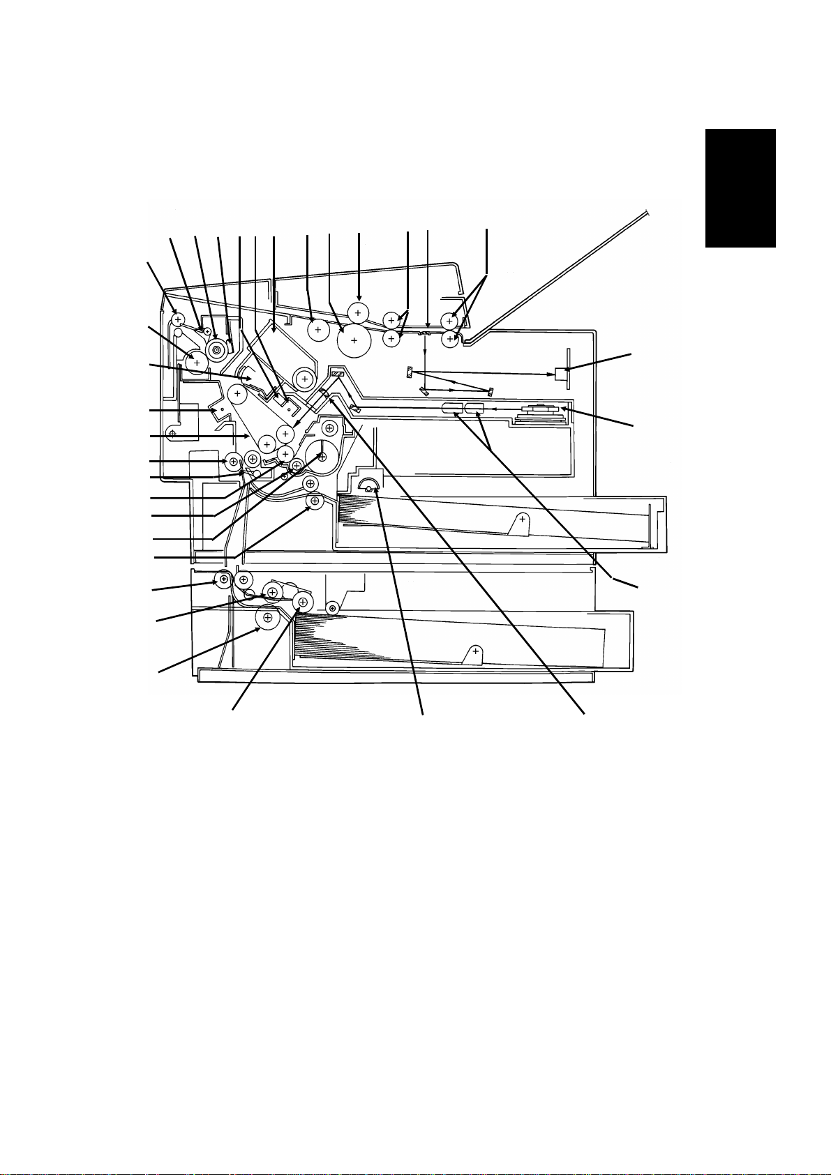
COM PONEN T LAYOUT
1.3. COMPONENT LAYOUT
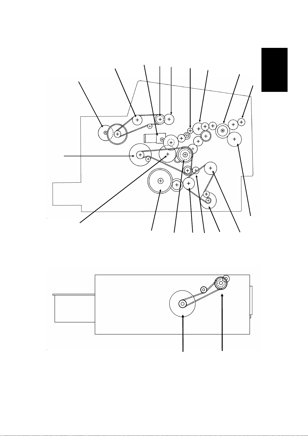
1.3.1. Mechanical Components
1
14
15
16
17
18
19
20
21
22
23
24
13
12
11
10
2
6789
45
3
1
32
31
30
25
26
27
1. R2 Rollers Feed the document through the scanner.
2. Exposure Glass Exposes the original to light from the xenon lamp.
3. R1 Rollers Feed the document through the scanner.
4. Separat ion Roller Allows on e page i nto the scann er.
5. Document Feed Roller Feeds the document into the scanner.
6. Pick -up R oller Picks up pages of the document from the document
table .
7. Toner Cartridge This supplies toner to the development unit. It is part of
the CTM (Cleaning/Toner Magazine).
8. Charge Corona Unit This applies a charge to the master at the start of the
print cycle.
9. Quenching L amp This removes excess charge from the master at the end
of the print cycle.
10. Thermistor This me asures the temperature in the f using unit.
11 . H ot Roller Hea t from this r oller f uses the toner to the copy paper.
28
29
1-5
Page 8

November 30th, 1991 OVERALL MACHINE INFORMATION
COM PONEN T LAYOUT
12 . H ot Roller Strippers These take the paper off th e hot roller af ter fusing.
13. Copy F eed-out R ollers These feed the paper out of the printer.
14. Pressure Roller (Fusing) This applies pressure to the paper during the fusing
process.
15. Cleaning Unit/Used Toner
Tan k
16. Transfe r C orona Unit This applies a charge to the paper to pull the toner off
17. Master Belt Also known as the CS (Compact Seamless) Engine. The
18. Registration R olle r This carries out the registration process.
19. Registration Sens or This dete cts when pape r is approaching the registra tion
20. Development Roller This roller applies toner to the latent image on the
21. Toner Supply Bar This feeds toner to the development roller.
22. Toner Mixing Bar This stirs up the toner in the development unit, so that it
23. Upper Rel ay Rollers The se fe ed paper from the u pper cassette into th e
24. Lower Relay Rollers These feed paper from the lower cassette into the
25. Lower Paper Feed Roller This feeds paper out of the lower cassette.
26. L owe r Paper Se pa ration
Roller
27. Lowe r Paper Pick-up Roller This picks up the t op sheet of paper from the stack in
28. Upper Paper Feed Rollers T hese pick up the top shee t of paper from th e stack in
29. Focusing Lens This focuses the laser beam onto the master belt.
30. Fθ Lenses These ensure that the thickness of the laser beam is
31. He xagonal Mirror This passes the laser beam across the mas ter belt.
32. CCD (Charge Coupled
Device)
This removes excess toner from the master after image
transfer and stores it. It is part of the CTM
(Cleaning/Toner Magazine).
the master a nd onto the copy paper.
latent image is writte n to this organic photoconductor
belt.
roller .
master belt.
does not collect into lumps.
printer .
printer.
This ensure s that only one shee t of paper at a time
leave s the lower cassette.
the lower cassette and pas ses it to the f eed roller.
the upper cassette a n d fe ed it into the printer.
uniform across the main scan.
This converts the light reflected from the document into
an analog video signal.
1-6
Page 9
567
13
14
15
OVERALL MACHINE INFORMATION November 30th, 1991
COM PONEN T LAYOUT
1.3.2. Drive Components
18
2
1
3
4
8
1
9
17
16
19
12
20
10
11
1-7
Page 10

November 30th, 1991 OVERALL MACHINE INFORMATION
COM PONEN T LAYOUT
1. Tx Motor This stepper motor drives the scanne r.
2. R2 Roller This feeds the original through the s canner.
3. Toner Supply Motor This dc motor drives the toner supply mechanism.
4. R1 Roller This feeds the original through the s canner.
5. Shutter Dri ve Gear This ensures that the shutter moves out of th e
document feed path at the correct time.
6. Toner Supply Gear (C TM) This ensure s the supply of toner from the CTM into the
development unit. It is part of the CTM.
7. Cleaning Brush Drive Gear This drives the cleaning brush in the C TM.
8. Hot Roller This fus es the toner to the copy pape r.
9. Copy Feed-out Roller This feeds printouts out of the machine.
10. Pressure Roller This applies pre ssure t o t he copy paper in t he fusing
unit.
11. Registration Roller Drive
Gear
12. Upper Paper Feed Motor This dr ives the paper feed mech anism in the upper
13. Development Roller Drive
Gear
14. Upper Paper Feed Roller
Drive Gear
15. Master Belt Drive Gear This drives the master belt.
16. Paper Feed Clutch This transfers drive from the upper paper feed motor to
17. Toner Supply Gear
(Development)
18. Ma in M otor T his brushless dc motor drives the ma s te r belt, fus ing
19. Lower Paper Feed Motor This drives the paper feed mechanism in the lower
20. Lower Paper Feed Clutch This transfers drive from the lower paper feed motor to
This drives the registration roller.
cassette.
This drive s the de velopme nt roller.
This drives the upper paper fee d roller.
the uppe r paper feed mechanis m.
This ensure s the collection of toner from the CTM, and
its distribution across the full length of the development
unit.
unit, development unit, and cleaning unit.
cassette.
the lower paper fe ed mechanis m.
1-8
Page 11
16
24
9
12
OVERALL MACHINE INFORMATION November 30th, 1991
COM PONEN T LAYOUT
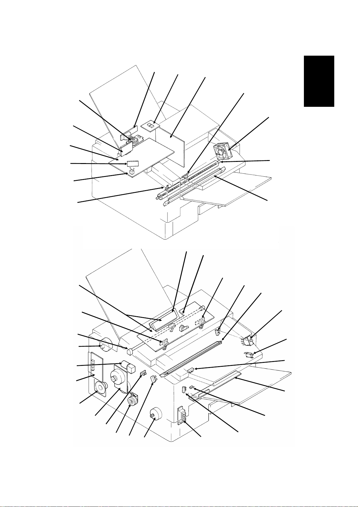
1.3.3. Electrical Components
1
13
11
2
3
4
5
1
10
8
37
35
34
36
14
14
15
15
6
7
17
18
19
20
33
32
31
30
29
28
27
26
21
22
23
25
1-9
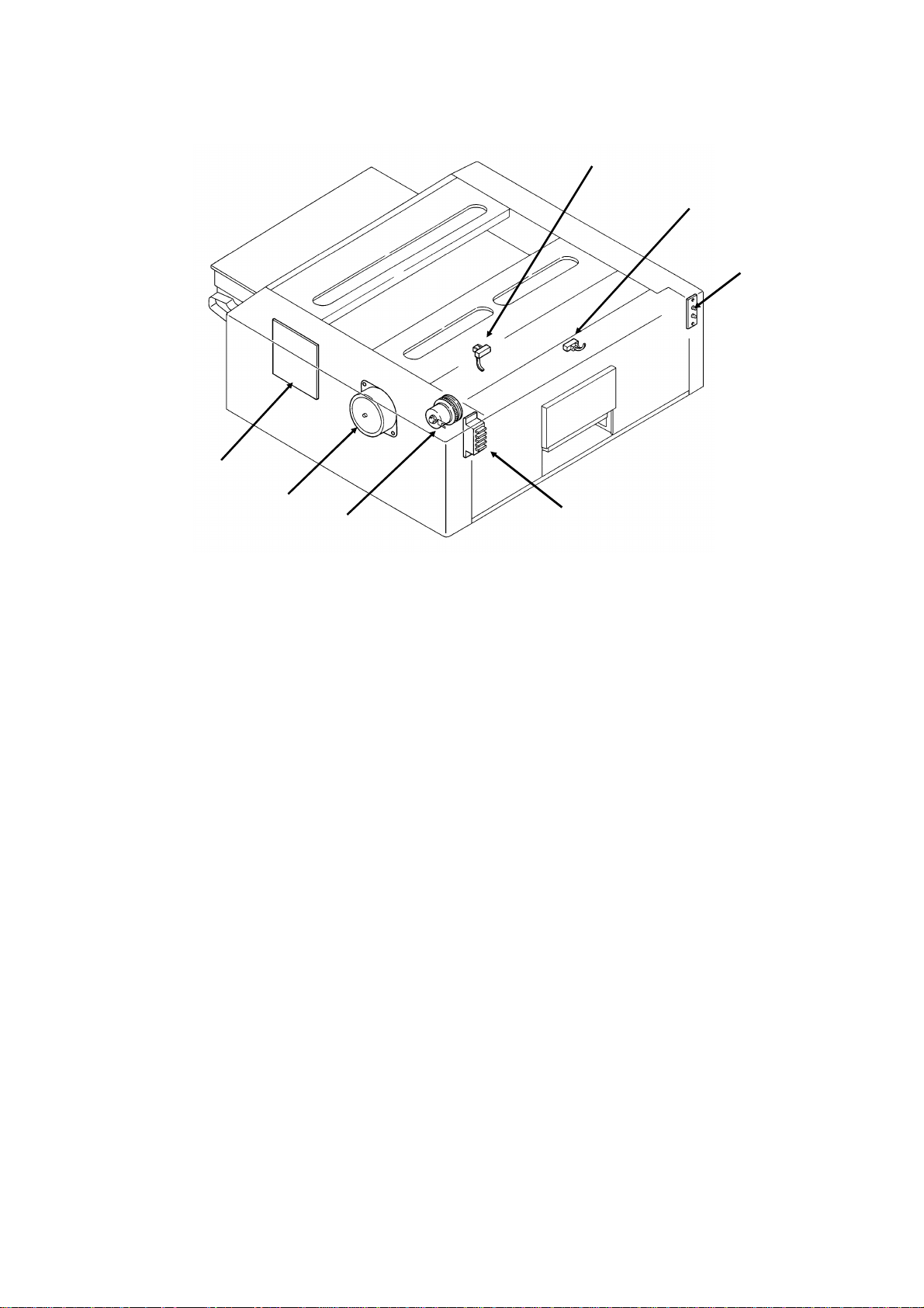
Page 12
November 30th, 1991 OVERALL MACHINE INFORMATION
COM PONEN T LAYOUT
Lower Ca ssette
44
43
42
Name Description No.
PCBs
FCU This board controls the machine. 11
MBU This board contains the system ROM and RAM for storing
system parameters such as bit switch settings and programmed
telephone numbers.
SBU This board contains the CCD. 1
OP- PORT Th is board controls t he operation panel. 37
NCU This board contains relays and switches for interfacing the
machine to the network and the handset.
PSU This board supplies power to the ma chine. 3
LD Unit This board drives the laser diode. 10
PF U T his board controls the lower paper fe ed unit. 4 4
MOTORS
Tx M otor This ste pper motor drives the scanner. 34
Main Motor This dc motor drive s the fusing unit, master belt, dev elopment
roller, and cleaning unit.
Upper Paper
Feed Motor
Lower Paper
Feed Motor
Toner Sup p l y
Moto r
Hexagonal Mirror
Motor
Ozone F an This removes ozone-laden air from the vicinity of the master unit,
This stepper motor drives the upper paper feed mechanism and
the registra ti on roller.
This stepper motor drives the lower pape r f eed mechanism. 43
This dc motor drives the toner s u pply mechanism. 33
This high-speed dc motor drive s the hexagonal mirror in the
lase r printer optics.
an d filter s out the ozone.
38
39
40
41
12
32
30
26
13
5
1-10
Page 13

OVERALL MACHINE INFORMATION November 30th, 1991
COM PONEN T LAYOUT
Name Description No.
CLUTCHES
Upper Paper
Feed Clutch
Lower Paper
Feed Clutch
SENSORS
Docum ent Sensor This detects the presence of a document in the feeder. 36
Scan Line Se nsor This detects when a page is approaching the auto sha ding
Document Width
Sensor
Toner Near-end
Sensor
Upper Paper Size
Detector
Upper Paper End
Sensor
Registration
Sensor
Paper Feed-out
Sensor
Front Cover
Switch
CT M Sensor This detects when a CTM has been ins ta lled in the machine. 27
Lower Paper Size
Detector
Lower Paper End
Sensor
Lower Paper
Feed Sensor
INT ERLOCK S WITCHES
Front Cover
Interlock
Switches
OTHERS
Spe aker This allows the user to listen to th e condition of th e telephone
Xenon Lamp This lamp illuminates the document. 35
Xenon Lamp
Driver
Charge Corona
and Quenching
Lamp Unit
Transfer Corona
Unit
Varistor This ensures that the charge given to the master by the charge
Marker This stamps a re d circle on each page that is successf ully f ed
T h i s transfe r s drive from the upper pape r feed motor to the
paper feed roller in the upper cassette.
T h i s transfe r s drive from the lower paper feed motor to the paper
fee d roller in the lower cassette.
position.
This detects when a B4-width [10.1"] document has been placed
in the feeder.
This detects when the toner has almost run out. 17
T h i s de tects th e paper s i ze installed in th e upper cassette. Th e
use r mu st install th e correct actuator.
This detects when the paper in the upper cassette ha s run out. 29
This detects when paper has arrived at the re gis tra tion rollers. 21
This detects when the paper has been fe d out of the printer. 24
This detects wheth er the front cove r is open or closed. 23
T h i s de tects th e paper s i ze installed in th e lower cass ette. T h e
use r mu st install th e correct actuator.
This detects when the paper in the lower cas sette has run out. 3 8
This sensor detects the presence of paper at t he lowe r paper
feed roller.
If the front cover is open, these interlock switches interrupt the
+ 5VLD power supply for the laser diode and the + 24VD power
supply f or t he power pack, motors, and oth er componen t s.
line.
This drives the xenon lamp. 2
The charge corona unit charges the ma s te r belt a t the s ta rt of
the print cycle. The quenching lamp re move s excess charge
from the master belt at the end of the print cycle .
This pulls the toner off the maste r and onto the copy paper. 7
corona wire does not exceed -750 Volts.
through the scanner.
28
42
14
16
25
41
39
19,
20
31
18
9
15
1
1-11
Page 14

November 30th, 1991 OVERALL MACHINE INFORMATION
COM PONEN T LAYOUT
Name Description No.
Power Pack This s upplies high voltages to the corona wires and the
developme nt bias terminal.
F using Lamp This fuses the toner to the paper. 6
Thermistor This monitors the te mperature inside the f us ing unit. 8
Thermostat This inte rrupts the ac power supply to the fusing lamp if the
temperature exceeds 400 °C.
Lower Cassette
Indicat or Pane l
T h i s conta i n s indicators to show the sta tu s of th e lower cass ette. 40
22
4
1-12
Page 15
OVERALL MACHINE INFORMATION November 30th, 1991
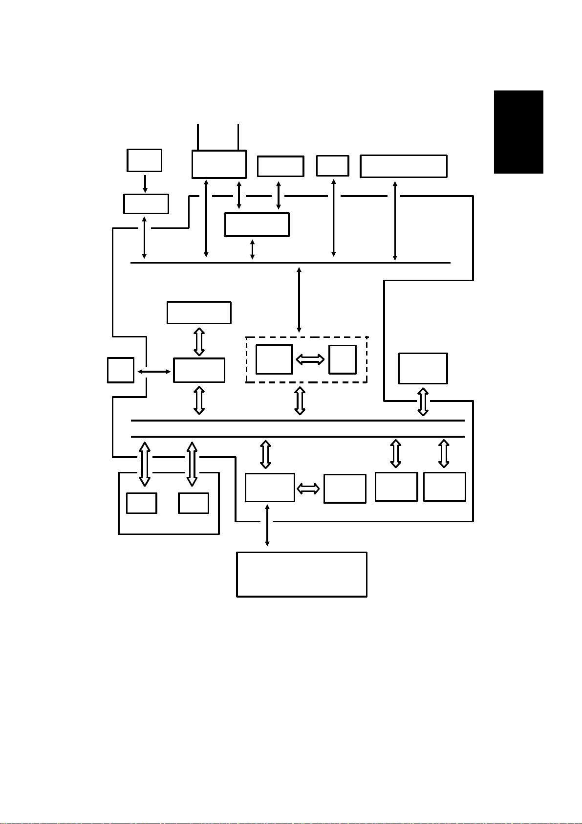
OVERALL MACHINE CONTROL
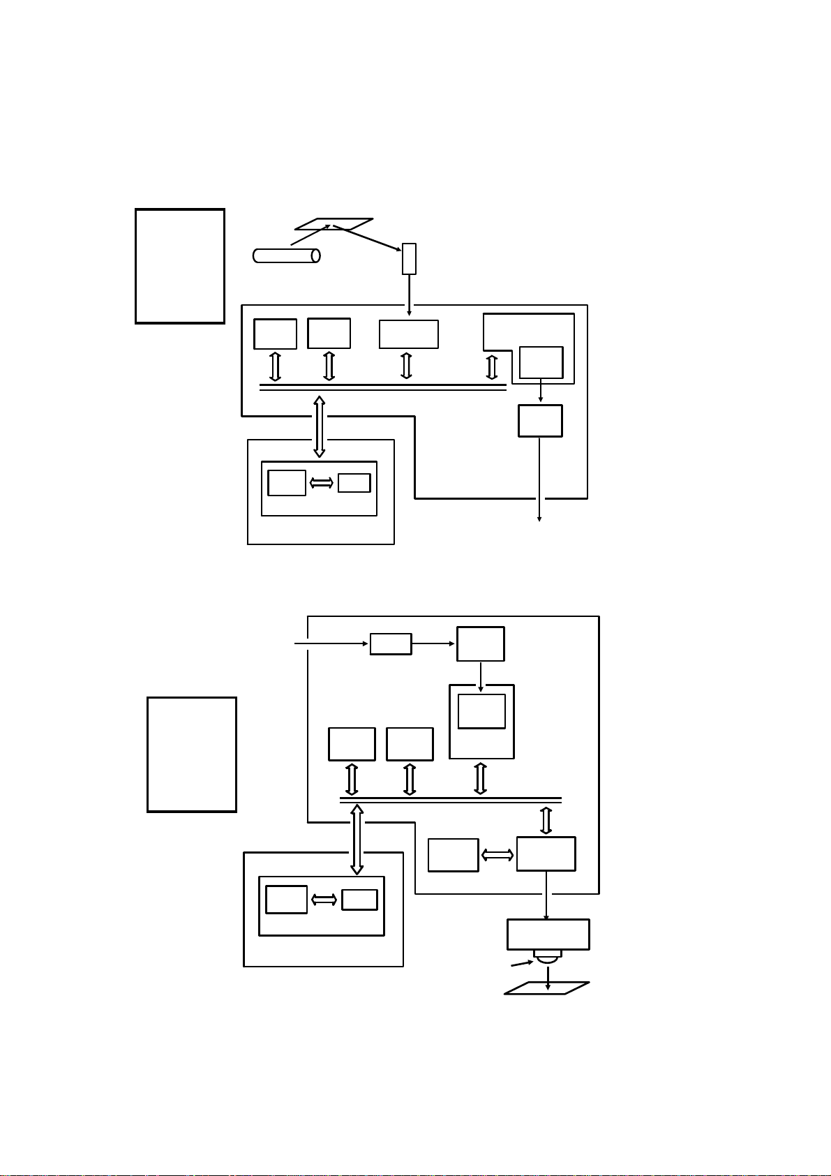
1.4. OVERALL MACHINE CONTROL
HandsetLine
1
SBU
(CCD)
Scanner
Sensors
Operation
Panel
NCU
CONTROL SIGNALS
Video Processing
Memory
Video
Processor
Speaker
Modem AFE
CPU
DATA AND ADDRESS BUS
PSU
Port
Scanner and Printer Drive
Components and Sensors
FCU
I/O
RS-232C
Interface
Laser
Interface
Page
Memory
SAF
Memory
ECM
Memory
RAMROM
MBU
Laser Diode Driver
Main Scan Start Detector
Interlock Switch
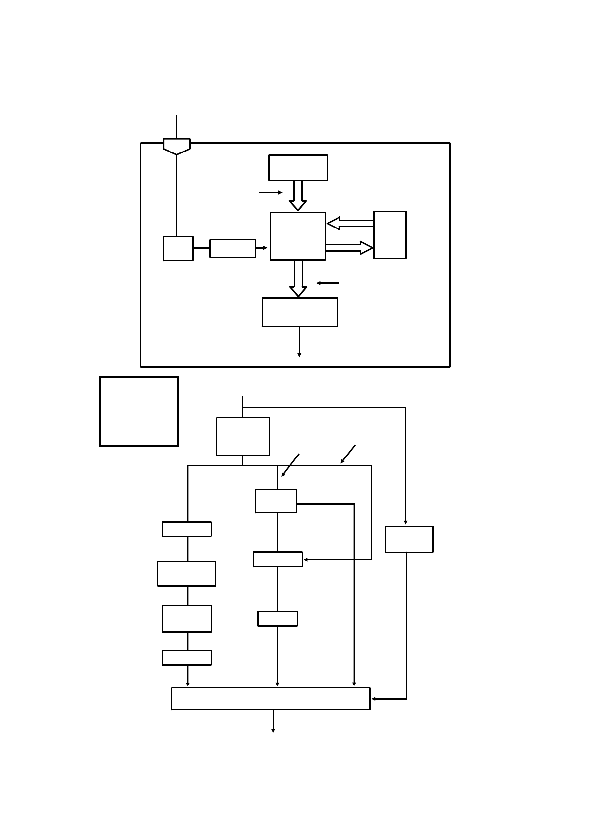
The cpu on the FCU board controls the machine, as shown in the above
drawing.
There is no modem board in the machine. The cpu pe rforms the digital functions of a modem and carries out digital to analog conversion of facsimile
data. There is a separate analog modem chip, called the Modem AFE, which
does the rest of the modem operations.
1-13
Page 16
November 30th, 1991 OVERALL MACHINE INFORMATION
VIDEO DATA PATH
1.5. VIDEO DATA PATH
1.5.1. Transmis sion
Original
Reference:
Group 3
Facsimile
Manual,
section
1-3-1
Xenon
Lamp
ECM
Memory
Line
Buffer
SAF
Memory
RAM
MBU
FIFO
Video
Processor
The fo llowing diag rams show
the data path for this model.
There is no programmable resis-
CCD
Analog Signal
FCU
MODEM
AFE
Modem
(Digital)
Modem
(Analog)
Network
(via the NCU)
tor in this model.
CPU
To the
1.5.2. Reception
From the
Network
(via the NCU)
Reference:
Group 3
Facsimile
Manual,
section
1-3-2
Line
Buffer
RAM
MBU
FCU
Memory
SAF
FIFO
Filter
HYBRID IC
Memory
ECM
Page
Memory
Laser Diode
Modem
(Analog)
Modem
(Digital)
CPU
MODEM
AFE
Laser
Interface
Laser Diode
Driver
1-14
Copy Paper
Page 17
OVERALL MACHINE INFORMATION November 30th, 1991
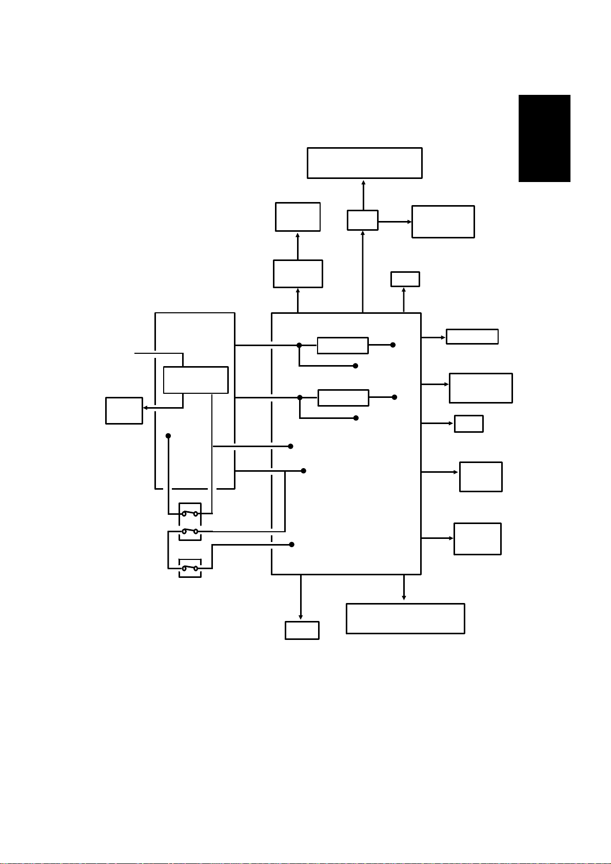
POWER DISTRIBUTI O N
1.6. POWER DISTRIBUTION
1.6.1. Distribution Diagram
Lower Paper Feed Motor
Lower Paper Feed Clutch
+24VD
1
AC Main
Power
Fusing
Lamp
PSU
AC Switching
Circuit
+24V
-12V
+24VS
+24VD
+5V
Scanner
Sensors
+5V
Operation
Panel
+5V
+24VD
Regulator
Regulator
+5V
+24VD
+5V
PFU
- 12V
+5V
+24VS
+24VS
+5V
NCU
FCU
- 5V
+12V
Sensors and
Indicators
FUSING UNIT
Thermistor
+5V
+5V
MBU
SAF Memory
+5V
SBU
+12V
+5V
Printer
Sensors
Front Cover
Interlock Switch
Front Cover
Microswitch
+5VLD
+5VLD
LDDR
Laser Diode
+24VD
Motors, Clutches, Lamps,
Marker, Power Pack
+5V
The laser diode is powered by a special + 5V supply, called + 5VLD.
There are two + 24V po wer supplies:
• + 24VS: This is always on when the main switch is on.
• + 24VD: Th is is interrupted if the front cover interlock switch opens.
There is no + 24VD activation sign al from the cpu to the PSU.
1-15
RS-232C
Interface
Page 18
November 30th, 1991 OVERALL MACHINE INFORMATION
POWER DISTRIBUTI O N
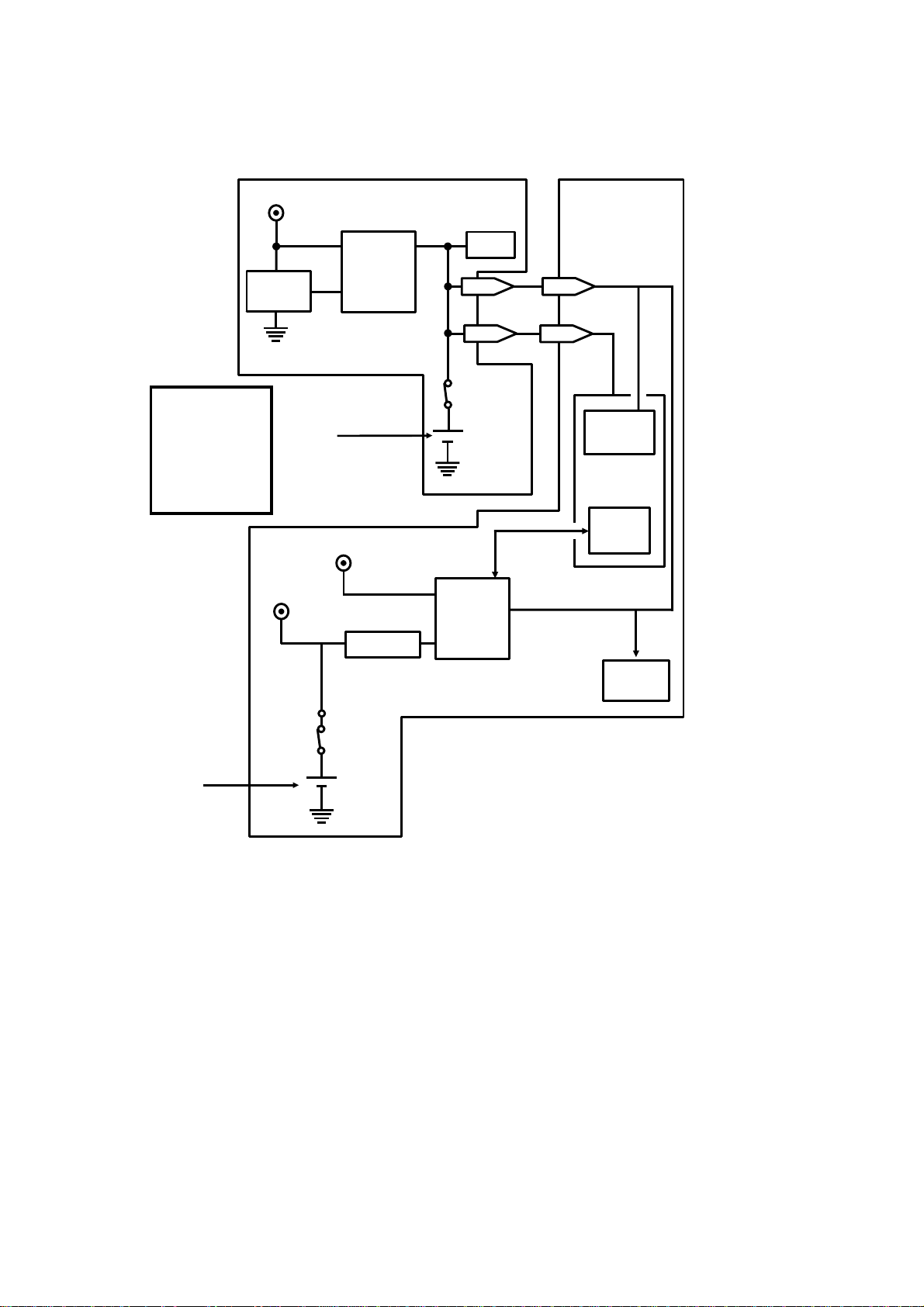
1.6.2. Memory Back-up Circuit
Reference:
Group 3
Facsimile
Manual,
sect i o n 1-4-3,
Circuit type 1
+5V
Voltage
Detector
+24V
[A]
+5V
Switching
Circuit
Regulator
MBU
RAM
1-11
1-9
Battery
Switch
Battery
Switching
Circuit
FCU
17-11
17-9
Real Time
Clock
CPU
Memory
Monitor
SAF
Memory
Battery
Switch
[B]
Battery
The battery [A] on the MBU backs up the RAM on the MBU, which contains
system parameters. It also backs up the real time clock in the cpu. This battery is not rechargeable. CN1-9 tells the cpu whether the back-up power
(CN1-11) comes from the battery or from the + 5V power supply.
A rechargeable battery [B] on the FCU board backs up the SAF memory and
the real time clock for 1 hour. While the main power is on, the + 24V supply
recharges the battery.
If there is data in the SAF memory, the rechargeable battery [B] also backs
up the real time clock, to preserve the MBU battery.
1-16
Page 19
[A]
DETAILED SECTION DESCRIPTIONS November 30th, 1991
SCANNER
2. DETAILED SE CTION DESCRIPTIONS
2.1. SCANNER
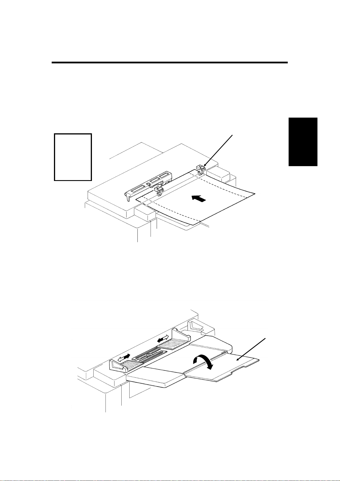
2.1.1. Mechanisms
1. Document Detection
Document Table
Reference:
Group 3
Facsimile
Manual,
section
2-1-1.
• The scanner is B4-width [10.1"] , with a B4 document width detector [A].
The scanner can feed paper u p to 304 mm [12"] wide. However, only
10.1" of this width will be scanned. The extra width allows users to feed
wide originals with wide margins, such as computer form printouts.
• The scanner contains a xenon lamp.
• There is a fold-down extension [B] to suppo rt long d ocuments.
2
[B]
2-1
Page 20
[A]
November 30th, 1991 DETAILED SECTION DESCRIPTIONS
SCANNER
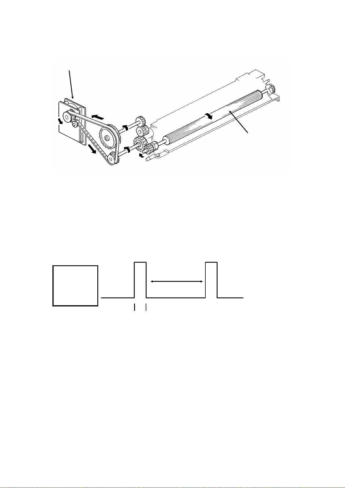
Shutter
[C]
[B]
Reference:
Group 3
Facsimile
Manual, section
2-1-1.
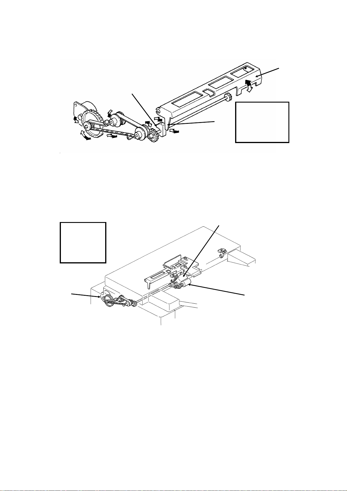
In standby mode, tab [A] rests on cam [B]. When the tx motor starts, the motor rotates forwards (white arrows), the cam lifts the tab, and the shutter [C]
rises. After the last page has been fed through the scanner, the tx motor reverses (black arrows), the cam drops back to the standby position, and the
shutter blocks the scanner path again.
2. Pick-up and Feed
Drive Mechanism
Reference:
Group 3
Facsimile
Manual,
sect i o n 2-2-1.
[A]
[B]
[C]
This ma chine has a Mechanical Clutch Mechanism. The tx motor [A] drives
the feed roller [B] and pick-up roller [C].
Resoluti on
Standard - The tx motor fe eds the document at 7 . 7 lines/mm. T he video processor executes
OR processing to convert the data into 3.85 lines/mm.
Detail - The tx motor feeds the document at 7.7 lines/mm. There is no OR processing, and
the data is transmitted at 7.7 lines/mm.
Fine - The tx motor feeds the document and transmits data at 15.4 lines /mm. If the other terminal cannot receive at this re solution, alternate lines of data are deleted, so the effective resolution of the transmitted data is 7.7 lines/mm.
2-2
Page 21
DETAILED SECTION DESCRIPTIONS November 30th, 1991
SCANNER
Jam Conditions
The cpu detects a document jam if one of the fo llowing conditions occurs.
• Th e scan line sensor do es not switch on within 9 s of the Start key be-
ing pressed.
• The scan line sensor does not turn off after the maximum document
length has been fed since it turned on.
• The scan line sensor switches on while the document sensor is off.
• The document width sensor switches on while the document sensor is
off.
• The scan line sensor does not turn on within 5 s of the end of stamping,
if the document sensor is on.
Separation
Reference: Group 3 Facsimile Manual, section 2-2-2
2
3. Manual Feed
[B]
[A]
The manual feed button [A] lifts the separation roller [B] out of the doc um ent
feed path. There is no manual feed switch.
Reference: Group 3 Facsimile Manual, section 2-2-3
2-3
Page 22
November 30th, 1991 DETAILED SECTION DESCRIPTIONS
SCANNER
2.1.2. Video Data Processing
Output from the CCD
A
Auto Shading
Memory
WHITE
WAVEFORM
FEEDBACK
Reference:
Group 3
Facsimile
Manual,
sect io n 2-3.
DC
Filter
VIDEO
PROCESSOR
Corrected Data from the Auto Shading Circuit
Amplifier
Gamma
Correction,
MTF
A/D
Converter
Data Processing
Circuits
Halftone
Process
Edge
Detection
To the CPU
and Modem
Basic
EDGE
ELEMENTS
Peak
Hold
CORRECTED
DATA
Error
Diffusion
Halftone
Process
Comparator
Background
Detection
OR
Processing
Reduction
A
NON-EDGE
ELEMENTS
Reduction
Halftone
B
Process Selector
To CPU and Modem
2-4
Image/Text
Detection
B’
Page 23
DETAILED SECTION DESCRIPTIONS November 30th, 1991
PRINTER
2.2. PRINTER
2.2.1. Mechanisms
1. Master Unit
This printer uses a "write to black" system, using negative toner.
The master unit contains a durable OPC master belt. The expected lifetime of
each master unit is about 60,000 copies (this is the target value). Because of
this long lifetime, the user is not expected to change the master; there is no
Replace Master indicator.
The master belt does not have a bond seam, so no master home position detection is needed. There is also no master unit interlock switch; there is an interlock switch on the front cover.
[A]
2
[B]
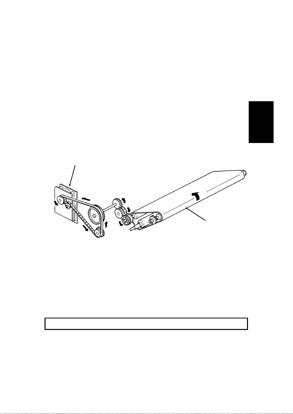
The main motor [A] dr ives the master belt [B].
• At the start of printing, it turns on briefly and the master belt moves un-
der the quenching lamp to ensure that it is fully discharged.
• Then, when the fusing lamp is at the correct temperature and the page
memory contains a complete page of data, and the hexagonal mirror
motor is running at the correct speed, the main motor switches on
again.
• When the main motor is running at the correct speed, the laser diode
turns on for automatic power control.
Reference: Group 3 Facsimile Manual, section 4-1
2-5
Page 24
November 30th, 1991 DETAILED SECTION DESCRIPTIONS
PRINTER
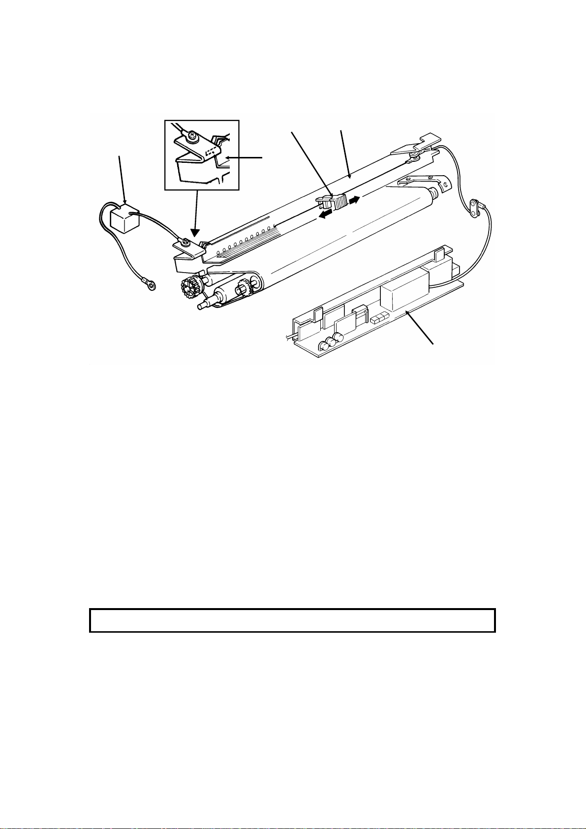
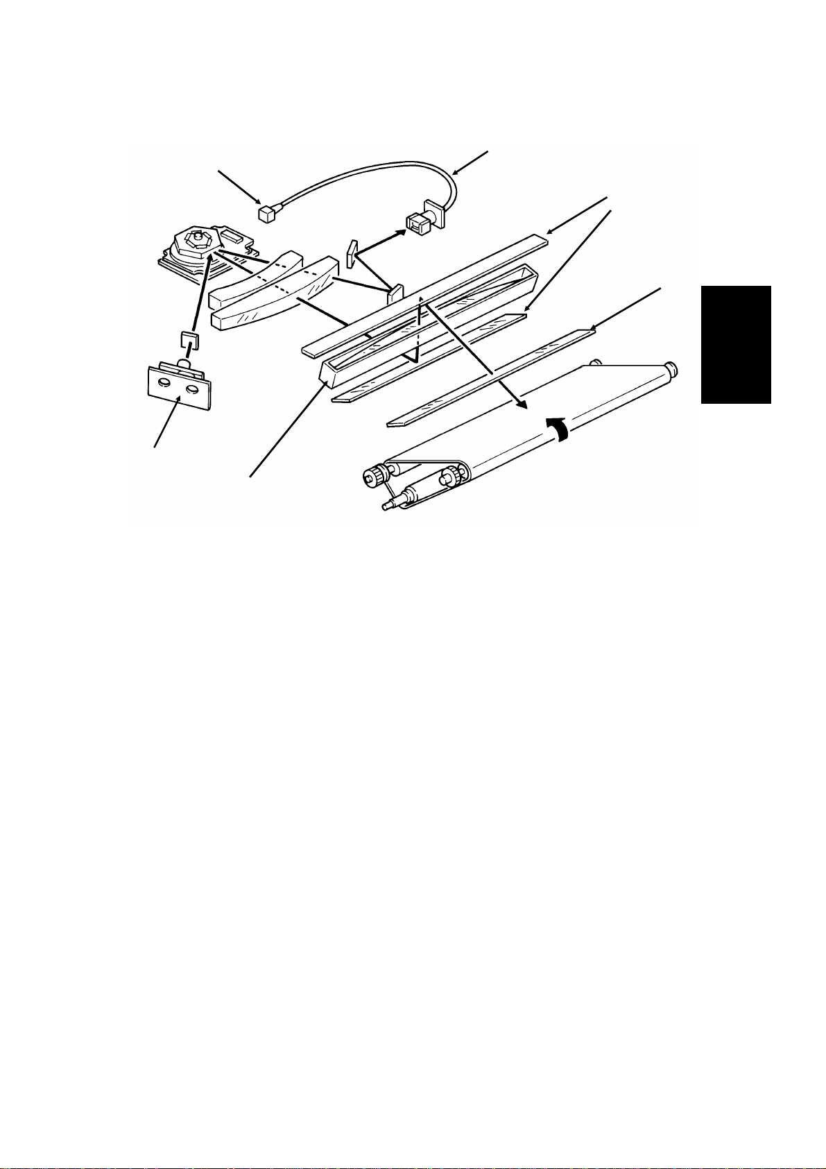
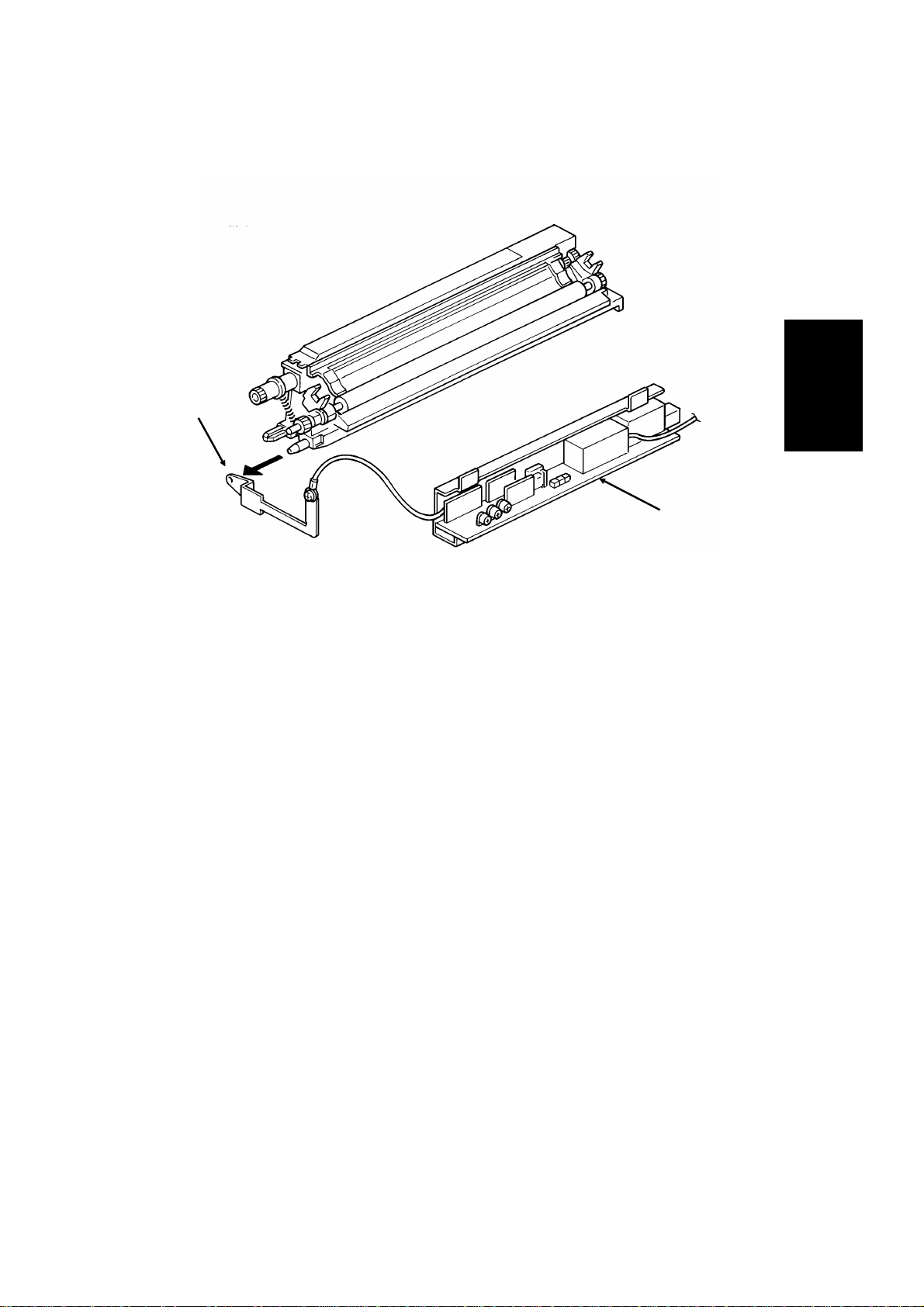
2. C harge Corona Unit
[D]
[B]
[E]
[A]
[C]
The charge corona unit [A] gives a -750 V charg e to the master belt. The
varistor [B] ensures that the charge does not exceed this value.
The connection between the power pack [C] and the corona unit is not broken when the front cover is opened. However, the front cover interlock switch
cuts the + 24V power line to the power pack if the cover is opened.
The charge corona unit contains a wire cleaner [D].
The charge corona switches on at the same time as the laser diode starts its
power control procedure.
There is one ozone fan on the right hand side of the machine. It sucks air out
of the mac hine through the ozone filter, which is part of the ozone fan assembly. The ozone fan switches on when a ringing signal is detected, and stays
on until the fusing lamp temperature falls back below 130 °C at the end of the
printing run.
The inset shows how the grid plate [E] connects to the varistor.
Reference: Group 3 Facsimile Manual, section 4-2
2-6
Page 25
DETAILED SECTION DESCRIPTIONS November 30th, 1991
PRINTER
3. Laser Optics
[E]
[F]
[B]
[D]
[A]
[C]
2
The optics are the same as those illustrated in section 4-3-3 of the Group 3
Facsimile Manual, except that there are two mirrors [A] at the "Second Mirror" position.
Other points to note are as follows:
• The focusing lens [B] is a barrel toroidal lens.
• The shield glass [C] pr events toner from entering the laser optics area,
and may need cleaning occasionally.
• An optical fiber [D] p asses the reflected laser beam to the main scan
start detector [E]. This detector is situated on the laser diode drive
board [F], unlike shown in the diagram.
• The strength of the b eam is 0.436 mW at a w avelength of 780 nm.
• The dimensions of the dot on the master belt are 65 µm (main scan di-
rection) by 75 µm (sub-scan direction).
The charge on the exposed parts of the belt drops to abo ut -150 V, while nonexposed areas remain at abo ut -750 V.
The laser engine characteristics are as follows (refer to page 4-3-21 of the
Group 3 Facsimile manual for background).
• Motor speed: 9,240 rpm
• Motor type: Hexagonal
• LD clock frequency: 5.3311 MHz
• Time between main scan synchronization signals: 1.082 ms
• Number of dots per main scan: 5769
2-7
Page 26
[A]
November 30th, 1991 DETAILED SECTION DESCRIPTIONS
PRINTER
4. Development
Overview
This machine uses a ’write-to-black’ development system using negative
toner.
The toner cassette is part of a disposable unit known as the CTM (Cleaning/Toner Magazine). The CTM contains a toner cassette, toner supply
mechanism, cleaning unit, and used toner tank. When the toner is all used
up, the CTM is replaced.
Reference: Group 3 facsimile Manual, section 4-4
Toner Supply
[B]
[C]
[E]
[D]
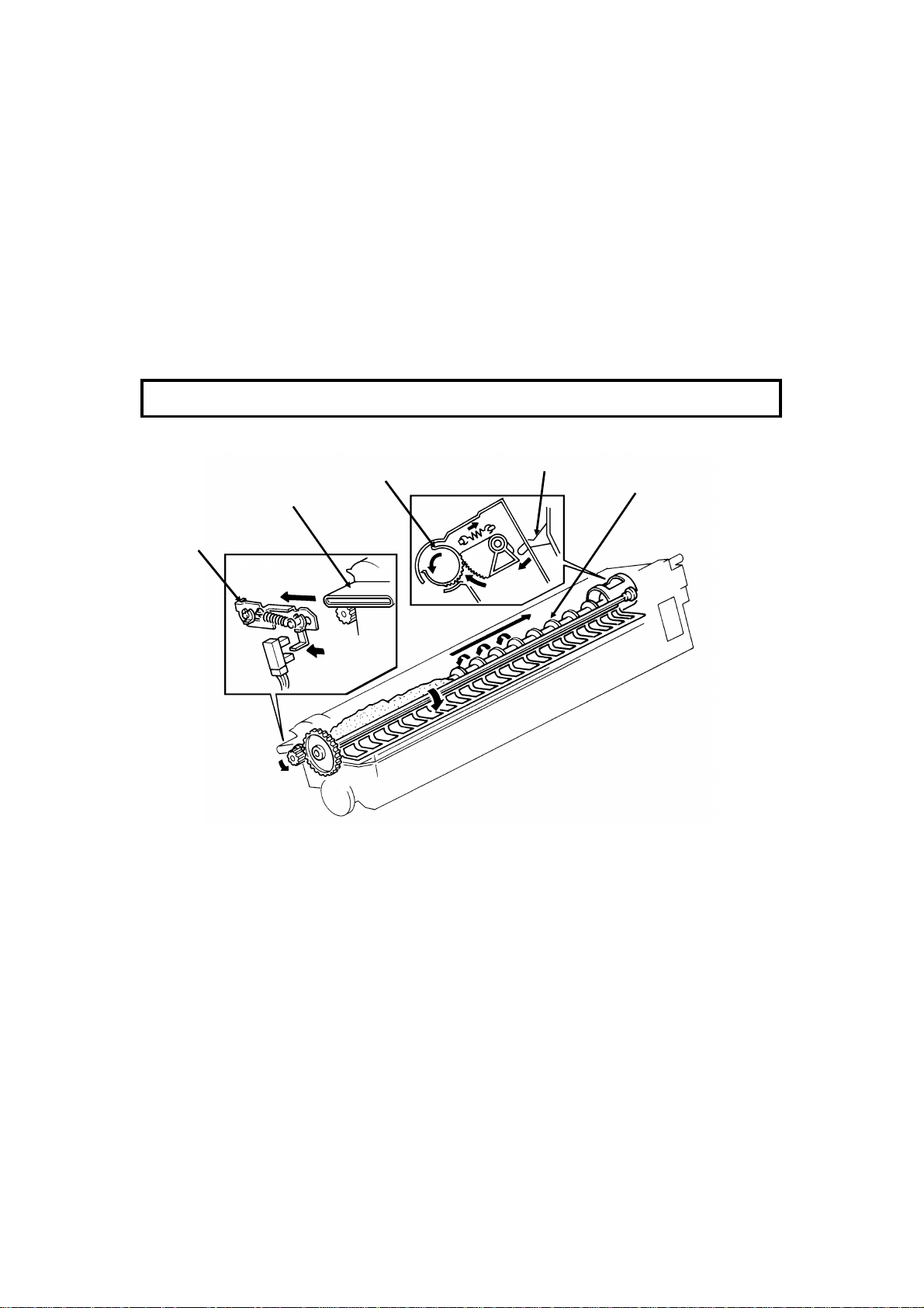
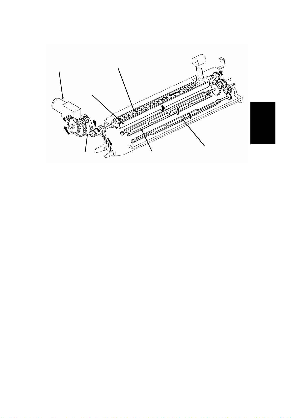
When a new CTM is installed in the machine and the front cover is closed,
the main motor and toner supply mo tor turn on. When the front cover is
closed, a tab [ A] on the fusing unit cover forces the hopper [B] to open.
Also, tab [C] on the CTM pushes bracket [D], which moves the CTM sensor
actuator into the sensor.
Continued on the next page
2-8
Page 27
DETAILED SECTION DESCRIPTIONS November 30th, 1991
PRINTER
[F]
[H]
[I] [J]
[G]
[K]
The toner supply motor [F] drives the toner supply shaft ([E] in the diagram
on the previous page). This spiral shaft feeds toner to the hopper.
Inside the development unit is another spiral shaft [G]. This shaft, driven by
the main motor, distributes toner across the length of trough [H]. The toner
supply motor drives gear [I], and once every rotation, it tips the trough upside down, dropping the toner into the development unit. A spring immediately pulls the trough back upright so that it can continue to receive toner.
2
The toner m ixing b a r [J], driven b y the main motor, k eeps the toner agitated
as it builds up at the bottom of the development unit. The toner supply bar
[K] supplies toner to the development roller.
While toner is being supplied, th e main motor is also operating the toner nearend detection mechanism. When a fresh toner cassette is installed, the sensor detects toner near-end, because there is not much toner in the
development unit. When some toner has been transferred, the signal from
the toner near-end sensor returns to normal. About 22 s after that, the toner
supply motor stops and no more toner is transferred into the development
unit.
During printing, if toner near-end is detected, the toner supply mechanism will
start up again. Toner will be supplied until the sensor signal returns to normal. If the toner cassette in the CTM is empty, no toner will be transferred,
and the sensor signal will not return to normal. If the sensor outputs the nearend signal for more than 5 minutes, the cpu blinks the Add Toner indicator.
See "Toner Near-en d Detection" fo r more details.
2-9
Page 28
November 30th, 1991 DETAILED SECTION DESCRIPTIONS
PRINTER
Development Unit Drive
[A]
[B]
During p rinting, d rive from the main motor at gear [A] drives the development
roller [B]. The main motor also drives the master belt, so the development
roller and the master belt always move at the same time; therefore, no development clutch is needed.
Toner Near-end Detection
The toner near-en d det ection mechanism is exactly the same as described in
section 4-4- 4 of the Group 3 Facsimile Manual. The sensor signal is as
shown in the following diagram.
Reference:
Group 3
Facsimile
Manual,
sect i o n 4-4-4.
1.9 s
0.1 ms
The cpu starts to blink the Add Toner indicator under the following conditions:
• At power up: If the sensor output indicates toner near-end for 6 s
• During printing: If the sensor output indicates toner near-end for more
than 5 minutes, totaled over consecutive print runs (when the motor
stops, the sensor mechanism is deactivated, so time between printing
runs does not count towards the 5 minute time limit)
After 100 more pages have been printed, the Add Toner indicator remains lit,
and printing is disabled until a new CTM has been added.
2-10
Page 29
DETAILED SECTION DESCRIPTIONS November 30th, 1991
PRINTER
Development Bias
[B]
[A]
2
The development bias and switching bias are supplied from the power pack
[A] at the same terminal [B].
• Development bias: - 530 ± 20 Vdc (BIASL)
• Switching bias: + 70 ± 20 Vdc (BIASH)
The switchin g bias is used at the following times :
• Between pages of a print run, while the development bias is off
• While toner is bein g transferred from the CTM to the development unit
2-11
Page 30
November 30th, 1991 DETAILED SECTION DESCRIPTIONS
PRINTER
5. Paper Feed
There are two cassettes, a 250-sheet cassette, and a 500-sheet cassette. In
some models, the 500-sheet cassette is an optional unit.
The sizes of paper that the cassettes can take are listed in the specifications
(section 1-1).
[A]
Paper feeds from the rear towards the front. The lower paper feed path
bends upward thro u gh the front part of the upper cassette. The two p ap er
feed paths merge just before the registration roller [A].
2-12
Page 31

[B]
[B]
DETAILED SECTION DESCRIPTIONS November 30th, 1991
PRINTER
Paper Lift
Standard Cassette
[C]
[A]
A mec hanical paper lift mechanism is used. When the us er places the cassette into the machine, a pin [A] in the base of the cassette activates a spring
loaded lever mechanism [B], which forces up the paper lift arm [C] until the
top of the stack touches the paper height positioner.
Lower Cassette
[A]
[C]
[E]
2
[D]
A mec hanical paper lift mechanism is used. When the us er places the cassette into the machine, a tab [A] on the rear of the cassette pushes a plate
[B] towards the rear of the machine as the user slides in the cassette. This
plate, driven by a spring [C], fo rces u p the paper lift arm [D]. The paper
height positioner [E] ensures that the paper is not pushed up too far.
Reference: Group 3 Facsimile Manual, section 4-5-2
2-13
Page 32

November 30th, 1991 DETAILED SECTION DESCRIPTIONS
PRINTER
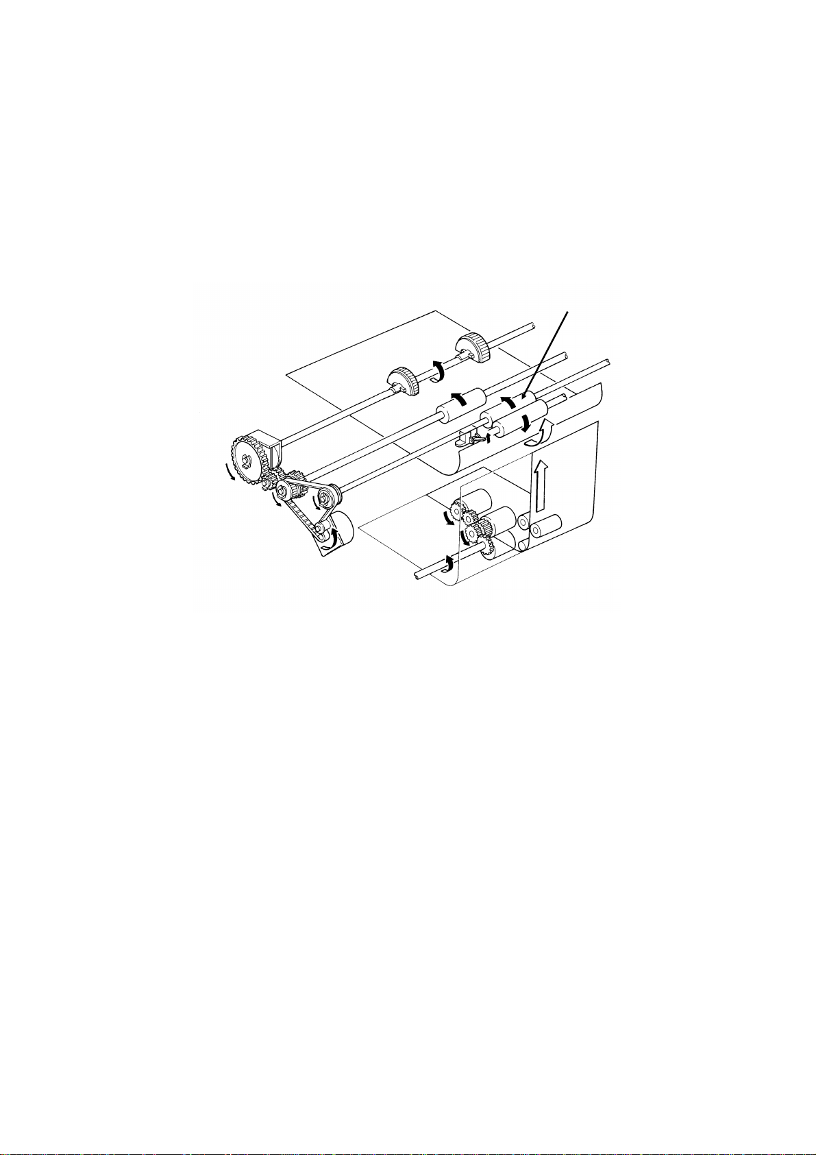
Pick-up and Feed Mechanism
Standard Cassette (Clutch Driven Single Roller Mechanism)
Reference:
Group 3
Facsimile
Manual,
sect io n 4-5-3.
[B]
[D]
[G]
[C]
[A]
[E] [F]
The upper paper feed motor [A] drives the pick-up and feed mechanism. The
paper feed clutch [B] transfers drive from this motor to the feed rollers [C].
When the paper feed clutch turns on, a metal plate [D] moves aw ay from
gear [E]. A pin [F] on this plate releases the gear, and the paper feed roller
turns. However, the clutch switches off after only 0.3 s, and a spring forces
the plate back to the starting position. After one revolution, the rib [G] on the
inside of the gear comes against the pin, and the paper feed roller stops.
When the page memory is full, the upper paper feed motor turns on. At the
beginning, it rotates at a slower speed (202.5 pps) to avoid excessive startup noise and start-up current peak.
At 0.1 s after the main m otor reaches the correct speed, the motor turns at a
higher speed (405 pps). This higher speed, us ed for pick-up and feed, ensures that time is not wasted getting paper into the printer. At the same time,
the upper paper feed clutch turns on and paper is fed into the printer.
Shortly after the registration sensor turns on, the main motor has the leading
edge of the paper, so the upper paper feed motor rotates at 202.5 pps again
to match the feed speed of the main motor.
When the trailing edge of the paper has left the registration sen sor, the pap e r
is no longer affected by the up per p aper feed motor. The upper paper feed
motor goes back to 405 pps ready for feeding the next page.
2-14
Page 33

DETAILED SECTION DESCRIPTIONS November 30th, 1991
PRINTER
Lower Cassette (Clutch Driven Two Roller Mechanism)
Reference:
Group 3
Facsimile
Manual,
sect io n 4-5-3.
[A]
[C]
[D]
[E]
2
[B]
The lower paper feed motor [A] drives the lower paper feed mechanism, and
the lower paper feed clutch [B] transfers drive from the motor to the lower
pick-up [C] and feed [D] rollers at the correct time.
When the page memory is full, the lower pape r feed motor turns on. At the
beginning, it rotates at a slower speed (266 pps) to avoid excessive start-up
noise and start-up current peak. After 0.1 s, the motor rotates at a higher
speed (800 pps). This higher speed of rotation, used during pick-up and
feed, ensures that little time is wasted in getting paper out of the cassette and
into the printer.
When main motor lock is achieved, the lower paper feed clutch turns on and
paper is fed into the printer. Shortly after the paper feed sensor [E] is activated, the clutch turns off.
After registration, the upper paper feed and main motors turn on to drive the
registration rollers and feed the pap er into the printer. However, rollers driven
by the lower paper feed motor still hold the t railing edge of the paper. So the
lower paper feed motor rotates at 266 pps to match the feed speed of the upper feed and main motors.
When the trailing edge of the paper has left the paper feed senso r, the paper
is no longer affected by the lo wer paper feed motor. The lower paper feed
motor goes back to 800 pps ready for feeding the next page.
2-15
Page 34

[B]
November 30th, 1991 DETAILED SECTION DESCRIPTIONS
PRINTER
Separation Mechanism
Standard Cassette
The standard cassette uses a semicircular roller and corner separator
method of separation.
Lower Cassette
This cassette uses a feed and reverse roller mechanism.
Reference: Gro up 3 Facsim ile Manu al (sect ion 4-5-4).
Registration
[C]
[D]
Reference:
Group 3
Facsimile
Manual,
sect io n 4-5-5.
[A]
[E]
Standard Cassette
There is no registration. This is because the upper paper feed motor [A]
drives the registration roller [B] and the upper paper feed rollers [C], and
there is no registration clutch. This means that the registration roller and the
paper feed rollers stop at exactly the same time.
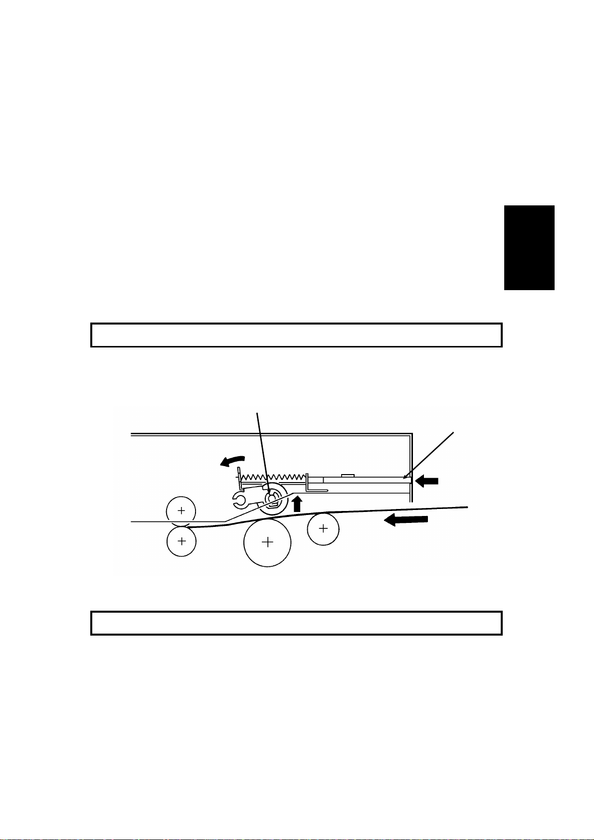
Just after the paper’s leading edge reaches the registration sensor [D], the
upper paper feed motor stops briefly.
Lower Cassette
The upper paper feed motor is off when the leading edge of the paper acti-
vates the registration sensor. The lower paper feed roller [ E] continues to
feed the paper for a short while after this, so registration is done in the normal manner (see section 4-5-5 o f the Group 3 Facsimile Manual).
2-16
Page 35

[A]
DETAILED SECTION DESCRIPTIONS November 30th, 1991
PRINTER
Jam Detection
The machine detects a jam if one of the following conditions exists.
• The registration sensor or copy feed-out sensor is activated while the
machine is in standby m ode.
• The registration sensor s till detects paper 9.0 s after th e paper feed
clutch turned on.
• The copy feed-out sensor still does not detect paper 9.0 s after the pa-
per feed clutch turned on.
• The copy feed-out sensor still detects the presence of paper 9.0 s after
it first detected the latest sheet of paper.
• Standard Cassette Only: The registration sensor does not turn on within
2.0 s after the upper paper feed clutch turned on.
• Lower Cassette Only: The lower paper feed sensor does not turn on
within 1.2 s after the lower paper feed clutch turned o n .
There is no err or detection during paper lift.
2
Paper Size Detection
Reference:
Group 3
Facsimile
Manual,
sect io n 4-5-9.
[B]
For both cassettes, the paper size actuator [A] is on the front of the cassette.
The pa per size sensor [B] is a row of microswitches. The above diagram
shows the upper paper size sensor.
The cpu disables paper feed from a cassette if the paper size cannot be detec ted. If the paper size actuato r is miss ing or broken, or if there is no cassette in the cavity, the Add Paper indicator will light.
2-17
Page 36

Lower Cassette
November 30th, 1991 DETAILED SECTION DESCRIPTIONS
PRINTER
Paper End Detection
Upper Cassette
[A]
[B]
Reference: Gro up 3 Fac sim i le Man ual , sec t io n 4-5-8.
[A]
[B]
In both cassettes, the paper end sensor actuator [ A] falls through a slot [B]
in the bottom of the tray.
There are no paper height sensors or paper near-end sensors.
Page Separation and Data Reduction
Incoming pages that are similar in length to the copy paper may be reduced
in the sub-scan direction to fit on the paper. Whether or not this happens depends on the settings of bits 1 and 2 of bit switch 02.
Reduction Enabled
If bit 2 of bit switch 02 is at 0, the data will be reduced in the page memory to
fit on the copy paper. However, data will only be reduced if the length of the
incoming page is between 5 mm shorter and a certain maximum length. This
maximum incoming page length that can be reduced depends on the copy
paper size and on the reduction ratio stored in RAM addresses 2404F and
24050.
Each paper size can be programmed with a separate reduction ratio. In each
of the two RAM addresses, there is one bit for each possible paper size. The
comb ination of the bit settings determines the ratio for that paper size.
Bit 7: Not used Bit 5: Legal Bit 3: A4 Bit 1: B5
Bit 6: B4 Bit 4: F4 Bit 2: Letter Bit 0: A5
The ratio is determined in accordance with the following table.
Bit in 2404F 0: 3/2 1: 4/3 0: 8/7 1: 12/11
Bit in 24050 0 0 1 1
2-18
Page 37

DETAILED SECTION DESCRIPTIONS November 30th, 1991
PRINTER
The following table shows the maximum incoming page lengths that can be
reduced for each copy paper size. All lengths are in millimetres. The factory
setting of the reduction ratio is 4/3.
Copy
Pap er Type
A5 148 214.5 190.7 163.4 156
B5 182 265.5 236 202.3 193.1
Letter 279.4 385
A4 297 385
F4, F 330.2 385
Legal 355.6 385
B4 364 385
1
: The page memory cannot reduce incoming pages longer than 385 mm.
Copy Paper
Length
Maximum reducable incoming page lengths
Ratio = 3/2 Ratio = 4/3 Ratio = 8/7 Ratio = 12/11
1
1
1
1
1
365.9 313.6 299.3
1
385
385
385
385
1
1
1
333.7 318.5
371.7 354.8
385 1 382.5
385 1 385
1
The values are calculated as follows.
Maximum incoming page length that can be reduced =
(Copy Paper Length - 5) x Reduction Ratio
For example, for A5 with a reductio n ratio of 4/3
Max incoming data length = (148 - 5) x 4/3 = 190.7
Incoming pages that are longer than the maximum length will not be reduced, but will be printed on two pages and treated in accordance with the
sett ing of bit 1 of bit switch 02. If this b it is 1, th e bottom few lines of the page
will be repeat ed at the top of the next page. If this bit is 0, the next page will
continue from where the first page left off.
2
Reduc tion Dis abled
If bit 2 of bit switch 02 is at 1, the data will not be reduce d. However, if the in-
coming page is up to x mm longer than the copy paper, the excess portion
will not be printed. The value of x can be from 0 to 15 mm. It is determined by
the setting of RAM addres s 24051 (copy mode: bits 3 to 0, receive mode:
bit s 7 to 4; bits 3 and 7 are the most significant bits).
Hex value Value of x
0 0
1 1
and so on until
15 15
Messages more than x mm longer than the copy paper will be printed out on
two pages in accordance with the setting of bit 1 of bit switch 02, as explained above.
2-19
Page 38

November 30th, 1991 DETAILED SECTION DESCRIPTIONS
PRINTER
Paper Size Selection
If there are two cassettes in the machine, the paper size to use is decided in
accordance with a few simple rules.
• If both cassettes contain the same paper size, the lower cassette will be
used.
• If the received page has to be split up and printed on two pages, both
pages will be the same size.
• If the cassettes contain different sizes, the paper size chosen for print-
ing the received fax m essage is selected in accordance with the following table of priorities. The table assumes that reduction is enabled and
that the reduct ion ratio is 4/3.
Paper Size
A5 Letter A4 F, F4 Legal B4
Recv’d
Fax
Message
Size
A5123456
Letter6(SR)12345
A4 6(SR) 2(R) 1 3 4 5
F, F4 6(SR) 5(R) 4(R) 1 2 3
Legal 6(SR) 5(R) 4(R) 3(R) 1 2
B4 6(SR) 5(R) 4(R) 3(R) 2(R) 1
• 1 is top priority.
• S: The data has to be separated and printed on more than one page.
• R: The data is reduced to fit on the printer paper.
• If Specified Cassette Selection has been switched on, messages from
specified senders will always go to the upper cassette, regardless of the
paper size or message size.
• Some of the reports can be printed on A5 paper without page separa-
tio n. However, if only A5 paper is in the cassettes, reports that need
larger paper sizes will require page separation.
2-20
Page 39

DETAILED SECTION DESCRIPTIONS November 30th, 1991
PRINTER
6. Transfer Corona Unit
[B]
[A]
2
The voltage o f the transfer coro na unit [A] is between 3.8 and 5.5 kV. It gives
a 200 V charge to the paper to pull the negative toner off the master belt. The
bend [B] in the m aster belt also helps the paper to leave the belt. There is no
antistatic brush to aid separation.
Reference: Group 3 Facsimile Manual, section 4-6
2-21
Page 40

November 30th, 1991 DETAILED SECTION DESCRIPTIONS
PRINTER
7. Fusing Unit
Fusing Unit Drive
[A]
The main motor [A] drives the fusing unit through a train of gears.
Fusing Unit Control
• Standby temperature: 65 °C
• Printing start tem perature: 130 °C
• Maximum printing temperature: 170 °C (monitored by a comparator)
• Thermistor maximum: 220 °C
• Thermostat maximum: 400 °C
When the main power is switched on, the fusing lamp heats up to 65 °C in
about 10 s.
When a ringing signal is detected (or when the user presses Start or Copy
for taking a copy), the fusing lamp heats up to 130 °C in about 15 s.
At the end of printing, the ozone fan stays on until the fusing unit temperature
has falle n below 130 °C.
Reference: Group 3 Facsimile Manual, section 4-7
2-22
Page 41

[A]
DETAILED SECTION DESCRIPTIONS November 30th, 1991
PRINTER
8. Cleaning
[C]
[B]
[C]
[A]
2
The CTM c ontains the cleaning unit and the used toner tank.
When the CTM is out of the machine, the cleaning blade [A] is forced against
a mylar plate, which prevents used toner from falling out.
When the CTM is placed inside the machine, a tab on the copy exit cover
pushes plate [B], which moves the cleaning blade away from the mylar and
against the master belt.
The cleaning blade wipes toner off the master belt as it passes the cleaning
unit. The toner goes to the used toner tank. The cleaning roller [C], driven by
the main motor removes any toner that may remain attached to the cleaning
blade.
There is no toner overflow detection me chanism. This is because the used
toner tank is removed with the old CTM when the toner cassette is empty;
the toner near-end sensor detects this.
Reference: Group 3 Facsimile Manual, section 4-9
2-23
Page 42

November 30th, 1991 DETAILED SECTION DESCRIPTIONS
PRINTER
9. Quenching
[A]
[B]
The quenching lamp [A] is an LED array. After quenching, the charge on t he
master [B] is about -20 V.
Reference: Group 3 Facsimile Manual, section 4-10
2-24
Page 43

DETAILED SECTION DESCRIPTIONS November 30th, 1991
PRINTER
2.2.2. Circuits
1. Laser Diode
Laser Diode Drive
Front Cover
Interlock Switch
AC/DC
Converter
+24V
1-1
Front Cover
Microswitch
PSU
1-2
3-8
2-1
+5V
1-1
20-5
8-1
8-2
FCU
+5V
2
+24VD
+5VLD
9-1
1-8
LDDR
Laser
Diode
Controller
Laser
Diode
The laser diode is powered by a special + 5V supply, called + 5VLD.
There are two s witches activated by the front cover; the fro nt cover interlock
switch, and the front cover microswitch. If either of these switches is open,
the power supply to the laser diode is interrupted.
The laser diode is not started until the following conditions have been met:
• The main and hexagonal mirror motor s are rotating at the correct
speeds
• The page memory contains a complete page
• The fusing lamp is at the printing temperature
2-25
Page 44

November 30th, 1991 DETAILED SECTION DESCRIPTIONS
PRINTER
Laser Diode Power Control
Laser
Power
Controller
1-2 1-4 1-5
DATA
Laser
Interface
Laser
Diode
LDDR
1-6
CONTROL FEEDBACKDISABLE
9-49-59-7
9-3
FCU
I/O
Port
CPU
The Laser Interface sends a constant signal to the laser diode on CN9-7, forcing the diode to stay on. The feedback signal returns to the FCU on CN9-3. If
necessary, the cpu adjusts the laser diode power to the correct value by altering the control signal (CN9-4).
If the cpu determines that laser diode power control has failed, it sends CN95 to low, which disables the laser diode.
Service Note
If one of the following occurs, the printer will be disabled, and an Auto Service Call will be sent to the service station (the message will be LD POWER
CONTROL FAILURE).
• If there is no response to laser power control (the cpu sends CN9-5
low).
• If the laser diode power supply (+ 5VLD) is cut.
2-26
Page 45

DETAILED SECTION DESCRIPTIONS November 30th, 1991
PRINTER
2. Fusing Unit
FUSING UNIT
Fusing
Lamp
Thermistor
36-2
+5V
36-1
LIVE
NEUTRAL
170 C [A]
4-1,4
4-3,6
36-3
I/O
Port
AC Switching
Circuit
3-1
36-4
[B]
PSU
3-2
[C]
1-8
Main
Power
Supply
1-7
2
FCU
The circuit shown in the above diagram controls the fusing unit.
• The I/O Port monitors the fusing unit temperature at CN36-1.
• The signal at CN36-4 (from the comparator [A]) remains low if the fus-
ing unit temperature is below 170 °C.
• The I/O Port switches the fusing unit on/off using signal [B].
• If the thermistor is accidentally disconnected, the link between CN36-3
and CN36-4 will also be broken. When the cpu detects this, an Auto
Service Call will be sent.
Standby mode
• If the fusing lamp is below 65 °C, t he I/O Port sends signal [B] low,
which makes CN1-8 go high. This switches on the fusing lamp.
• If the fusing lamp goes abo ve 65 °C, [B] goes high, and CN1-8 goes
low, which switches off the fusing lamp.
Continued on the next page
2-27
Page 46

November 30th, 1991 DETAILED SECTION DESCRIPTIONS
PRINTER
Printing
• When a rin ging signal is detected, CN1-8 goes high, to switch on the
fusing lamp. Also, the ozone fan switches on.
• During printing, the temperature is kept at 170 °C. If the temperature
rises above 170 °C, the output from the comparator changes state.
CN36-4 goes high, while [B] remains low. This causes CN1-8 to go low,
which switches off the fusing lamp.
• If the comparator fails, there are additional safety cutoffs at 220 °C (ther-
mistor) and at 400 °C (thermostat).
After printing
• When the fusing lamp temperature falls back below 130 °C, the ozone
fan switches off.
Service Note
When one of the following error conditions occurs, the I/O Port switches off
the fusing lamp by raising CN1-7 to high. The printer will be disabled, and an
Auto Service Call will be sent to the service station (the message will be HOT
ROLLER DOWN).
Standby mode
• If the fusing lamp takes more than 30 s to reach 65 °C
During printing
• If the fusing lamp takes more than 40 s to r ise to 130 °C from 65 °C
• If the fusing lamp stays above 170 °C for more than 5 s
After printing
• If the fusing lamp takes more than 10 minutes to fall back to 130 °C
At any time
• If the fusing lamp temperature reaches 220 °C
• If the thermistor is accidentally disconnected (see the previous page for
details)
2-28
Page 47

DETAILED SECTION DESCRIPTIONS November 30th, 1991
PCBs AND THEIR FUNCTIONS
2.3. PCBs AND THEIR FUNCTIONS
2.3.1. FCU
HandsetLine
SBU
(CCD)
Scanner
Sensors
Operation
Panel
Speaker
Modem AFE
CONTROL SIGNALS
Video Processing
Memory
Video
Processor
NCU
CPU
HIC
PSU
I/O
Port
Scanner and Printer Drive
Components and Sensors
2
FCU
RS-232C
Interface
MBU
DATA AND ADDRESS BUS
Laser
Interface
Page
Memory
SAF
Memory
ECM
Memory
RAMROM
Laser Diode Driver
Main Scan Start Detector
Interlock Switch
2-29
Page 48

November 30th, 1991 DETAILED SECTION DESCRIPTIONS
PCBs AND THEIR FUNCTIONS
1. CPU (AFSP)
• 65C02 compatible microprocessor
• Interrupt control
• DMA control
• Data compression and reconstruction (high speed MH coding for 4.5-
second scanning)
• Modem (digital operations)
• Real time clock (battery backed-up)
• Memory control
• Control of all mechanisms (directly or through other chips)
• NCU control (through the I/O Port)
2. I/ O Port (LIOP)
• Clock control
• Sensor monitoring (including A/D conversion where necessary)
• Tone detection
• Motor drive
• Operation panel control
• Laser Interface control
3. Laser Interface (LIF)
• Page memory control
• Laser diode control
• Smoothing
4. Modem Analog Front End (Modem AFE)
• Modem (analog operations)
• Attenuation
5. Video Processor (VPP)
• Analog/digital video signal processing
6. Hybrid IC (HIC)
• Filters
7. RAM
• 128k for ECM (no back-u p)
• 256k SAF memory (with battery back-up)
• 768k page memory
2-30
Page 49

DETAILED SECTION DESCRIPTIONS November 30th, 1991
PCBs AND THEIR FUNCTIONS
2.3.2. MBU
System
ROM
DATA AND ADDRESS BUS
Memory Back-up
Control
+
To/From
FCU
1. System ROM
• Contains the software to run the machine
MBU
2
System
RAM
To/From
FCU
2. System RAM
• 32k SRAM and 32k PSRAM for parameter storage, line buffer, FIFO,
SAF memory administration
The SRAM is backed up by the battery on the MBU.
2-31
Page 50

November 30th, 1991 DETAILED SECTION DESCRIPTIONS
PCBs AND THEIR FUNCTIONS
2.3.3. SBU
Analog Video
To the FCU
Drive Clocks
From the FCU
Drivers
CCD
+12V
+12V
+
Emitter
Follower
Inverter
Amplifier
SBU
2.3.4. OPU
LCD Panel
LCD Panel
Controllers
Operation Panel
Keys
Operation Panel
Operation Panel
Controller
Serial Interface
To/From FCU
LEDs
Output
from the
Scanner
Sensors
2-32
Page 51

DETAILED SECTION DESCRIPTIONS November 30th, 1991
PCBs AND THEIR FUNCTIONS
2.3.5. LDDR
2.3.6. PFU
Lower Cassette
Sensors
DATA
Laser
Power
Controller
CONTROL
To/From FCU
PFU
POWER
Indicator
Panel
Lower Cassette
Controller
Driver
Laser
Diode
LDDR
2
Lower Cassette
Mechanical
Components
Serial Interface
To/From FCU
2-33
Page 52

November 30th, 1991 DETAILED SECTION DESCRIPTIONS
PCBs AND THEIR FUNCTIONS
2.3.7. NCU
TIP
RING
T1
R1
To
Network
To
Handset
Protection
Circuit
FG
Line
Current
Detector
Oh
Relay
Di Switch
Ringing
Signal
Detector
Tx/Rx Data
To/From FCU
To FCU
+24V
Off-Hook
Detector
From FCU
To FCU
NCU
• For simplification, relay drive signals and detector outputs to/from the
FCU are not shown on this diagram.
• In the above diagram, the relays are shown in the standby position for
Auto Receive (Fax) Mode.
2-34
Page 53

DETAILED SECTION DESCRIPTIONS November 30th, 1991
PCBs AND THEIR FUNCTIONS
2.3.8. PSU
LIVE
NEUTRAL
GROUND
AC Power
to the
Fusing Lamp
Prevention
Arrestor
Fusing Lamp
Enable
From FCU
Surge
+24VD
AC Switching
Circuit
To
FCU
Main
Switch
+24VD
From
Front Cover
Interlock
Switch
Noise
Filter
+24V
To
Front Cover
Interlock
Switch
Surge Current
Prevention
+24V
To
FCU
Power Supply
Generation
Circuits
+5V
To
FCU
PSU
2
-12V
To
FCU
Overhea t Protection in the PSU
If the PSU thermistor temp erature exceeds about 100 °C, the power supply
outputs from the PSU are disabled.
If this happens:
1. Switch off t he machine.
2. Take out the PSU and examine it for damage. Take care because it may
be hot.
3. Put back the PSU and switch the machine on. If the machine does not operate, change the PSU.
2-35
Page 54

INSTALLATION November 30th, 1991
CONNECTING UP THE MACHINE
3. INSTA LLA TION
3.1. CONNECTING UP THE MACHINE
POWER SWITCH
115 ± 20V
60 ± 1 Hz
Grounded
3
Phone
Company’s
Jack
HANDSET
3-1
Page 55

Installation Procedure
1. Install the master unit. (refer to the Installation Manual for Ricoh Master Unit Type 30)
2. Install the toner cartrige. (refer to the Installation Procedure on the carton box)
3. Install the handset and connect the line. (refer to the Installation Manual)
4. Install the paper cassette. (refer to the Operation Manual)
5. Attach the trays and document table.
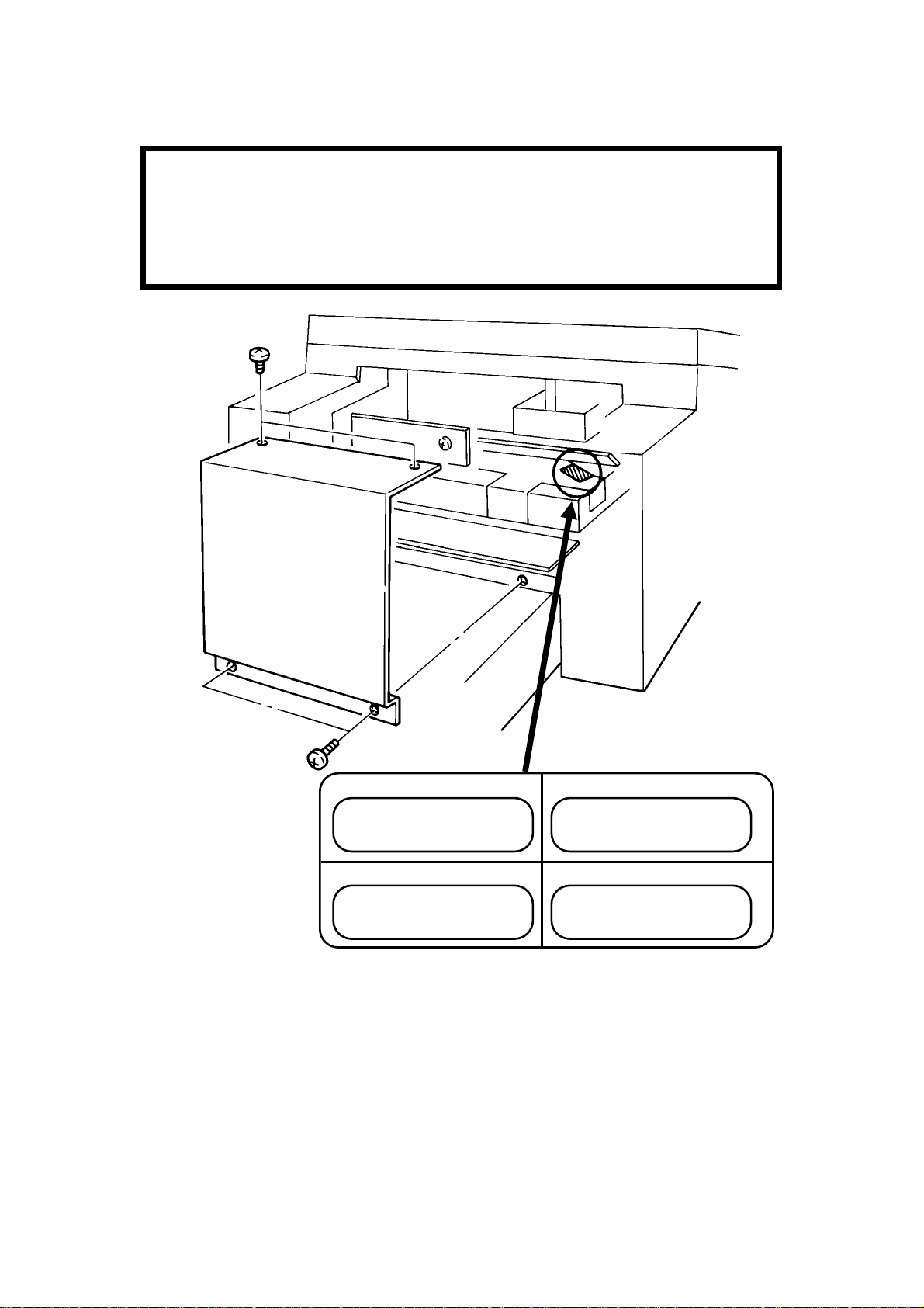
Page 56

[B]
[A ]: 1 screw
November 30th, 1991 INSTALLATION
INSTALLING ADDITIONAL UNITS
3.2. INSTALLING ADDITIONAL UNITS
3.2.1. Lower Cassette
Check whether there are any messages in the memory. If there are, you
must install the lower cassette and turn the power back o n within an hour.
[A ]
[B]
[D]
[C]
[C]
Fit pegs [B] into holes [C].
[D]: 5 screws
3-2
Page 57

[F]
[G]
[H]
INSTALLATION November 30th, 1991
INSTALLING ADDITIONAL UNITS
[F]
[E]
[E]: 2 connectors
3
Re move two screws [F].
[G]
Install brackets [G] (2 screws each).
Screws [H]: Use previously re moved
screws [F].
Screws [I]: In the accessories bag.
[I]
3-3
Page 58

November 30th, 1991 INSTALLATION
INSTALLING ADDITIONAL UNITS
[J]
Adjust the cassette in accordance
with customer requirements.
3-4
Page 59

INSTALLATION November 30th, 1991
INSTALLING ADDITIONAL UNITS
3.2.2. Memory Card
• Tur n off the power before installing or removing a memory c a rd.
• Make sure that 100% is displayed on the operation panel before install-
ing or removing a memory card, or data will be lost.
3
3-5
Page 60

November 30th, 1991 INSTALLATION
INSTALLING ADDITIONAL UNITS
3.2.3. Cassette (250 Sheets)
3-6
Page 61

INSTALLATION November 30th, 1991
INSTALLING ADDITIONAL UNITS
3.2.4. Cassette (500 Sheets)
3
3-7
Page 62

[B]: 2 screws
November 30th, 1991 INSTALLATION
INSTALLING ADDITIONAL UNITS
3.2.5. Handset
[A]
[A]: 2 screws
[B]
3-8
Page 63

INSTALLATION November 30th, 1991
INITIAL PROGRAMMING
3.3. INITIAL PROGRAMMING
Check the following:
• Is the country code in the NCU parameters (Function 96, parameter 00)
correct for the country of installation? In the USA, it should be 17.
• Do any bit switch or other settings have to be changed to match line
conditions or user requirements?
• Have you programmed the serial number (Function 98, section 4-1-18)?
The user should program the following items after installation:
• Telephone Line Type
• RTI, TTI, and CSI
• ID Codes (ID Code, Remote ID, Confidential ID, Memo ry Lock ID)
• The fax mac hine’s own teleph one number
• Date and Time
• Language Selection
3
3-9
Page 64

SERVICE TABLES AND PROCEDURES November 30th, 1991
SERVICE LEVEL FUNC TIONS
4. SERVICE TABL ES A ND PROCEDURES
4.1. SERVICE L EVEL FUNCTI ONS
4.1.1. Bit Switch Programming (Function 91)
1. Function 5 1 9 9 1
then immediately Yes
2. 9 1 Yes
FUNCTION Y/∇
9 SERVIC E FUNCTI ONS
DEFAULT: 0000 0000
BITSW 00: 0000 0000
Bit 7 is displayed at the left, and bit 0 at
the right.
3. Increment bit switch: #
Decrement bit switch:
*
Example: Display bit switch 3: # x 3 DEFAULT: 0000 0000
BITSW03: 0000 0000
4. Adjust the bit switch.
Example: To change the value of bit
7, press 7
DEFAULT: 0000 0000
BITSW03: 1000 0000
5. Either:
• Adjust more bit switches - go to step 3.
4
• Finish - Function
4.1.2. System Parameter List (Function 92)
1. Function 5 1 9 9 1
then immediately Yes FUNCTION Y/∇
9 SERVIC E FUNCTI ONS
2. 9 2 Yes START
SYSTEM REPORT
3. Start
After printing, press Function
4-1
Page 65

November 30th, 1991 SERVICE TABLES AND PROCEDURES
SERVICE LEVEL FUNC TIONS
4.1.3. Error Code Display (Function 93)
1. Function 5 1 9 9 1
then immediately Yes FUNCTION Y/∇
9 SERVIC E FUNCTI ONS
2. 9 3 Yes ERROR CODE #/∇
1-01 JAN 01 17:30
3. Either:
Scroll through the error codes - #
Finish - Function
4.1.4. Service Monitor (Function 93)
1. Function 5 1 9 9 1
then immediately Yes FUNCTION Y/∇
9 SERVIC E FUNCTI ONS
2. 9 3 Yes ERROR CODE #/∇
1-01 JAN 01 17:30
3. No/∇ Start
4.1.5. Protocol Dump (Function 94)
1. Function 5 1 9 9 1
then immediately Yes FUNCTION Y/∇
9 SERVIC E FUNCTI ONS
2. 9 4 Yes
START
PROTOCOL DUMP LIST
3. Start
4-2
Page 66

SERVICE TABLES AND PROCEDURES November 30th, 1991
SERVICE LEVEL FUNC TIONS
4.1.6. RAM Display/Rewrite (Function 95)
1. Function 5 1 9 9 1
then immediately Yes FUNCTION Y/∇
9 SERVIC E FUNCTI ONS
2. 9 5 Yes Y/∇
DISPLAY MEMORY
3. Ye s ADDRESS = 2044C
DATA = 03
4. Input the address that you wish to see. Example: Addr ess 20202
2 0 2 0 2 ADDRESS = 20202
DATA = 00
Note: The first digit must always be 2.
5. If you wish to change the data, type in the new data.
Example: 80, press 8 0 ADDRESS = 20202
DATA = 80
Note: If you wish to move the cursor, press
→
6. Either:
• View more addresses - go to step 4.
• Finish - Yes Function
4.1.7. RAM Dump (Function 95)
1. Function 5 1 9 9 1
then immediately Yes FUNCTION Y/∇
9 SERVIC E FUNCTI ONS
2. 9 5 Yes Y/∇
DISPLAY MEMORY
3. ∇ Ye s MEMORY DUMP START/N
B= 2, ST-0000,END-00FF
4
4. Input the bank number (B) and the start and
end addresses. Max. range: 256 bytes
Example: Start at 1200, end at 12FF.
1 2 0 0 1 2 F F Start MEMORY DUMP START
4-3
The value of B is always 2.
B= 2, ST-1200,END-12FF
Page 67

November 30th, 1991 SERVICE TABLES AND PROCEDURES
SERVICE LEVEL FUNC TIONS
4.1.8. NCU Parameters (Function 96)
1. Function 5 1 9 9 1
then immediately Yes FUNCTION Y/∇
9 SERVIC E FUNCTI ONS
2. 9 6 Yes NCU PARAMETER KPAD/Y
NO.00 001
3. Scroll through the parameters - Yes
Enter new values at the keypad.
Example: Set NCU parameter 04 to 005.
Yes Yes Ye s Ye s 0 0 5 NCU PARAMETER KPAD/Y
NO.04 005
4. To finish: Function
Note: Parameter 00 is the Country Code, and Parameter 01 is the Tx Level
(if the Tx level should be -9 dB, input 9).
Refer to section 4-3 for full details on NCU parameters.
4.1.9. ADF Test (Function 97)
1. Function 5 1 9 9 1
then immediately Yes FUNCTION Y/∇
9 SERVIC E FUNCTI ONS
2. 9 7 Yes
3. 1
SCN-1 DT-2 PL-3 LD-4
MDM -5 RI-6 CK-7 SN-8
SCANNER TEST KPAD
ADF-1 LAMP-2
4. 1
5. Function Function
6. Place a docu ment in the feeder,
then press Copy Start
4-4
Page 68

SERVICE TABLES AND PROCEDURES November 30th, 1991
SERVICE LEVEL FUNC TIONS
4.1.10. Xenon Lamp Test (Function 97)
1. Function 5 1 9 9 1
then immediately Yes FUNCTION Y/∇
9 SERVIC E FUNCTI ONS
2. 9 7 Yes SCN-1 DT-2 PL-3 LD-4
MDM -5 RI-6 CK-7 SN-8
3. 1 SCANNER TEST KPAD
ADF-1 LAMP-2
4. 2 SCANNER LAMP TEST
The xenon lamp lights up for 5 minutes.
4.1.11. DTMF Tone Test (Function 97)
1. Function 5 1 9 9 1
then immediately Yes
2. 9 7 Yes
3. 2
FUNCTION Y/∇
9 SERVIC E FUNCTI ONS
SCN-1 DT-2 PL-3 LD-4
MDM -5 RI-6 CK-7 SN-8
DTMF TEST
DUAL-1 SINGLE-2
4. Either:
• Test dual tones - 1 . Go to step 5.
• Test single tones - 2 . Go to step 8.
5. The display is as shown opposite. DUAL TONE
PRESS KEYPAD
Press a key on the ten key pad.
Example: 1 Start
4
6. To stop the test: Stop
7. Either:
Test another tone: Go to step 5.
Finish: Function
4-5
Page 69

November 30th, 1991 SERVICE TABLES AND PROCEDURES
SERVICE LEVEL FUNC TIONS
8. The display is as shown opposite.
Press the required key.
697 Hz 1 852 Hz 3 1209 Hz 5 1477 Hz 7
770 Hz 2 941 Hz 4 1336 Hz 6 1633 Hz 8
Example: To test 1633 Hz, press 8 Start
9. To stop the test: Stop
10. Either:
Test another tone: Go to step 8.
Finish: Function
4.1.12. Printer Test Patterns (Function 97)
SINGLE TONE
PRESS KEYPAD
1. Function 5 1 9 9 1
then immediately Yes FUNCTION Y/∇
9 SERVIC E FUNCTI ONS
2. 9 7 Yes SCN-1 DT-2 PL-3 LD-4
MDM -5 RI-6 CK-7 SN-8
3. 3 PATTERN PRINT KPAD
1-7
4. Press a key from 1 to 7, excluding 5 and 6. (Patterns 5 and 6 are not
used in this model.) A test pattern is printed.
4.1.13. Operation Panel Test (Function 97)
1. Function 5 1 9 9 1
then immediately Yes FUNCTION Y/∇
9 SERVIC E FUNCTI ONS
2. 9 7 Yes SCN-1 DT-2 PL-3 LD-4
MDM -5 RI-6 CK-7 SN-8
3. 4
4-6
Page 70

SERVICE TABLES AND PROCEDURES November 30th, 1991
SERVICE LEVEL FUNC TIONS
4.1.14. Modem Test (Function 97)
1. Function 5 1 9 9 1
then immediately Yes FUNCTION Y/∇
9 SERVIC E FUNCTI ONS
2. 9 7 Yes SCN-1 DT-2 PL-3 LD-4
MDM -5 RI-6 CK-7 SN-8
3. 5 MODEM TEST
G3-1 TONE-2
4. Either:
Test G3 carrier signals - 1 . Go to step 5.
Test frequencies - 2 . Go to step 8.
5. The display is as shown opposite. 9600-1 7200-2
4800-3 2400-4 300-5
Press the required key.
Example: Test the 9600 bps carrier 1 Start
6. To stop the test: Stop
7. Either:
Test another tone: Go to step 5.
Finish: Function
8. The display is as shown opposite. 2100-1 1100-2 800-3
PRESS KEYPAD
Press the required key.
Example: To test 1100 Hz, press 2 Start
9. To stop the test: Stop
10. Either:
• Test another tone: Go to step 8.
4
• Finish: Function
4-7
Page 71

November 30th, 1991 SERVICE TABLES AND PROCEDURES
SERVICE LEVEL FUNC TIONS
4.1.15. Ringer Test (Function 97)
Not used; do not try to use this function.
4.1.16. Buzzer Test (Function 97)
1. Function 5 1 9 9 1
then immediately Yes
2. 9 7 Yes
FUNCTION Y/∇
9 SERVIC E FUNCTI ONS
SCN-1 DT-2 PL-3 LD-4
MDM -5 RI-6 CK-7 SN-8
3. 7
Press the St op key to stop the buzzer.
4.1.17. Ozone Fan Test (Function 97)
1. Function 5 1 9 9 1
then immediately Yes FUNCTION Y/∇
9 SERVIC E FUNCTI ONS
2. 9 7 Yes SCN-1 DT-2 PL-3 LD-4
MDM -5 RI-6 CK-7 SN-8
3. 8
Press the Function key to stop the fan.
4.1.18. Serial Number (Function 98)
1. Function 5 1 9 9 1
then immediately Yes FUNCTION Y/∇
9 SERVIC E FUNCTI ONS
2. 9 8 Yes
SERIAL # KPAD
3. Enter the machine’s serial no at the keypad.
SERIAL # KPAD/Y/N
7940479186
To correct a mistake: No
4. If the display is correct: Yes
4-8
Page 72

SERVICE TABLES AND PROCEDURES November 30th, 1991
SERVICE LEVEL FUNC TIONS
4.1.19. Service Station Telephone Number (Function 99)
1. Function 5 1 9 9 1
then immediately Yes FUNCTION Y/∇
9 SERVIC E FUNCTI ONS
2. 9 9 Yes TEL NUMBER KEYPAD
3. Input the telephone number of the service station that will receive Auto
Service calls from this machine.
TEL NUMBER KPAD/ Y/N
2125555242
4. Yes Function
4.1.20. Bypassing Restricted Access
Use this procedure if the user has switched on Restricted Access. This enables you to use the machine without having to input a Personal Code. It is
also useful if the user cannot operate the machine because they cannot remember any of the Personal Codes.
1. 2 2 2 2
2. Immediately press Quick Dial key 11
Then operate the machine as you wish. When the machine is returned to
standby mode, Restricted Access is reimposed immediately.
4.1.21. Printing all Memory Files (Function 24)
First, set bit 5 of bit switch 01 to 1.
1. Function 2 4 Yes FI LE NO
2. Press No/∇ Ye s Start .
4
All files in the memory, including confidential messages, will be printed one by
one. The files will not be erased.
After you have finished, set bit 5 of bit switch 01 back to 0.
Note: To erase memory files, set bit 2 of bit switch 00 to 1. All files will be
erased, and some RAM addresses will also be cleared.
4-9
Page 73

November 30th, 1991 SERVICE TABLES AND PROCEDURES
BIT SWI TCHES
4.2. BIT SWITCHES
WARNING
Do not adjust a bit switch that is described as "Not used", as this
may cause the machine to malfunction or to operate in a manner
that is not accepted by local regulations. Such bits are for use only
in other areas, such as Japan.
Bit Switch 00
FUNCTION COMMENTS
0 MTF process
0: Enabled 1: Disabled
1 RAM reset level 2
1: Reset
2 R AM reset level 3
1: Reset
Note: RAM reset level
1 is a RAM
adjustment. It is not
described in this
manual.
3 Memory file forwarding
1: F orwa rd the f i les
4 Inclusion of technical
data on the TCR
0: No 1: Yes
5 Monitor speaker
during video data
communication (tx
and rx)
0: Disabled 1: Enabled
6 Not used Do not cha n ge the factory setting.
Continued on the next page
0: The MTF proces s is used when required by the software.
1: The MTF process is never used.
When this bit is set to 1, all items stored in the RAM are reset
except the cl ock , and then this bit changes back to 0
automatically. Also, all image files in the SAF memory are
erased.
When this bit is set to 1, some items stored in the RAM are
reset, then this bit changes back to 0. All items are reset
except the bi t switch and NCU paramete r settin gs, clock,
own tel. no., CSI, R TI, TTI, Quick Dials, Speed Dials, Groups,
and the TCR memory. Also, all image files in the SAF
memory are erased.
This bit switch is recommended for use when it is necessary
to cle ar the SAF, as fewer RAMs will nee d reprogramming.
Use this if the printer does not work, but the user wis hes to
print the files. F irst, change the fax machine’s tele phone
number (Function 51) to the number to which you wis h to
forwar d the files, then set thi s bit to 1. All fi les i n the me mory
will be forwarded. This bit resets to 0 automatically. However,
you must return the fax machine’s tele phone number to the
original setting. The file s stay in memory.
1: Instead of the personal code, the f ollowing data are listed
on the TCR as a six-figure number.
Fi rst t wo num bers: F inal modem rate (for example, 96
means 9,600 bps)
Second two numbe rs (Rx mode only): Rx signal level (Level
= 0 - 0.375x, where x is the value on the report; accurate to
3 dB)
Third two numbers (R x mode only): R x cable equalizer; 00
= Equalizer is Off, 01 = Equalizer is On
Used f or testing. Set this bit to 1 to hear the fax data s ignal
(phase C of CCITT T. 30 protocol).
Mak e sure tha t you r eset this bit after testing.
4-10
Page 74

SERVICE TABLES AND PROCEDURES November 30th, 1991
BIT SWI TCHES
Bit Switch 00
FUNCTION COMMENTS
7 Communication
paramete r dis play
0: Disabled
1: Enabled
Communication parameter display
This is a fault-finding aid. The L CD shows the ke y
parameters (s ee below). This is normally disable d because it
cancels the CSI display for the user.
Mak e sure tha t you r eset this bit after testing.
Modem rate
(bps)
96: 9600
72: 7200
48: 4800
24: 2400
Bit Switch 01
0
LCD contrast
Bit 2 1 0 Contrast
1
0 0 0 Brightest
0 0 1 ↓
2
↓ ↓
1 1 0 ↓
1 1 1 Darkest
Memory read/write by RDS
Bit 4 3 Setting
3
0 0 Always enabled
0 1 User selectable
4
1 0 User selectable
1 1 Always disabled
5 De dicat ed transmission para m eter
programming/printing all SAF f iles
0: Disabled 1: Enabled
6 Not use d Do not change the factory settin g.
Continued on the next page
Sub-scan
Resolution
S: 3.85 l/mm
D: 7.7 l/mm
F: 15.4 l/mm 1E: MH+ EFC
FUNCTION COM M ENTS
Coding Width and
reduction
1D: MH
2D: MR
2E: MR+ EFC
1C: MH+ ECM
2C: MR+ ECM
MC: MMR+ ECM
A: A4 [8.3"]
B: B4 [10.1’]
C: A3 [11.7"]
N: No reduction
R: Reduction
Use these bit switches to adjust the brightness
of th e LCD on th e operat ion pane l.
(0,0): At any time, an RDS system can read or
write RAM data such as TTI and bit switches.
(0,1), (1,0): Normally, RDS systems are locked
out, but the user can temporarily switch RDS
on to allow an RDS operation to take place.
R DS will a utomatically switch off again after a
certain time, which is stored in a RAM address
(see section 4-5). Note that, if an RDS
operation takes place, RDS will not switch off
until this time limit has expired.
(1,1): All RDS systems are always locked out.
T h i s bit must be se t to 1 before attempting to
program de dicat ed transmission para m eters or
printing all files stored in the SAF memory.
DCS:
CCITT G3
NSS:
Nonstandard G3
Mode I/ O Rate
(ms/line)
0M: 0
5M: 5
10M: 10
20M: 20
40M: 40
4
4-11
Page 75

November 30th, 1991 SERVICE TABLES AND PROCEDURES
BIT SWI TCHES
Bit Switch 01
FUNCTION COM M ENTS
7 Auto Service Call for PM
0: Enabled 1: Disabled
Bit Switch 02
FUNCTION COMM ENTS
0 Page separation mark
0: Enabled 1: Disabled
1 R epetition of data when the
received page is longe r than the
printer paper
0: Disabled 1: Enabled
2 Reduction of t he length of
receive d data
0: Enabled 1: Disabled
3 Not used Do not change th e factory settin gs .
4
5
Maximum transmittable document
length
6
Bit 7 6 Setting
0 0 600 mm
7
0 1 1200 mm
1 0 14 m
1 1 100 m
0: The machine will se nd an Auto S ervice Cal l
when the P M inte rv al has e xpired. This interval
is adjusta ble by RAM address. The default
setting is every 30,000 copies (based on the
Print counter).
1: The user will do maintenance as explained in
the Operator’s Manual whenever problems
occur.
0: If a receive d page ha s to be printed out on two
shee ts, an "x" inside a s ma ll box is printed at the
bottom right hand corner of th e first sheet, and a
"2" inside a small box is printed at the top right
hand corner of the second she et. This helps the
user to identify pages that have been split up.
1: No marks are printed.
0: The next page continues f rom where the
previous page left off
1: The fina l few mm of the previous page ar e
printed at the top of the next page.
See section 2-2-1, subsection 5, for details.
This bit determines whether incoming pages are
reduced to fit on the copy pa per if they are
almos t th e same length as the copy paper in the
cassette. See section 2-2-1, subsection 5, for
details.
If the user wants to send very long documents
such as well logs, use the 14 m or 100 m setting.
4-12
Page 76

SERVICE TABLES AND PROCEDURES November 30th, 1991
BIT SWI TCHES
Bit Switch 03
FUNCTION COMM ENTS
0 Dialing with the handset off-hook
0: Enabled
1: Disabled
1 Lifetime of polling standby files in
the memory
0: Erased after being polled
1: K ept until user erases
2 Inclusion of communications on
the TCR when no image data was
exchanged.
0: No 1: Yes
3 Printing of the error code on the
error report
0: No 1: Yes
4 Not use d Do not change the factory s etting.
5 Printing the TTI in copy mode
0: No 1: Yes
6 Printing the receive d RTI/CSI
0: No 1: Yes
7 R econs tru ction time for th e first
line in receive mode
0: 6 s 1: 10 s
If this bit is 1, the us er will not be able to dial if
the handset is off hook.
0: Me s s ages stored for polling transmission will
be erase d immediately a f te r polling.
1: T h i s setting allows the user to keep me ssages
in the m emory to be polled by more than on e
station.
If communica tion did not reach phase 3 of CC I TT
T.30 protocol (such as for a tele phone call), this
communication can be listed on the TCR if this
bit is at 1.
If this bit is 1 , error codes are printed on the e rror
reports for the use r.
If this bit is 1, the TTI stored in the machine is
printed at the top of the copy.
In addition to the TT I, the other end’s RTI or CSI
will be printed on top of the pages that the
machine receive s.
Whe n the s ending terminal is controlled by a
computer, there m ay be a delay in receiving page
data after the local machine accepts set-up data
and sends CF R. If this occurs, set this bit to 1 to
give the se nding machine more time to send
data.
4
4-13
Page 77

November 30th, 1991 SERVICE TABLES AND PROCEDURES
BIT SWI TCHES
Bit Switch 04
FUNCTION COMM ENTS
Compression modes available in
receive m ode
0
Bit 1 0 Modes
0 0 MH only
1
0 1 MR or MH
1 0 MR or MH, with
EFC
1 1 MMR, MR, or
MH, with EFC
2 Error counting method
0: 10 (20) [40]
1: In a ccordance with the settings
of bit s 3 to 7
Burst error thres h old
3
Bit 4 3 Threshold
0 0 3 (6) [12]
4
0 1 4 (8) [16]
1 0 5 (10) [20]
1 1 6 (12) [24]
Error line ratio
5
Bit 7 6 5 Value
0 0 0 5%
6
0 0 1 6%
0 1 0 7%
7
0 1 1 8%
1 0 0 9%
1 0 1 10%
The se bits determine what capabilities are
informed to the transmit t ing side in the pr ot ocol
exchange.
The machine counts data errors caused by a
noisy line or defective machine.
0: If the count reaches 10 (Standard mode), 20
(Detail mode), or 40 (Fine mode), the ma chine
sends RTN to the other end in reply to the postmessage com m and. A s 10 (or 20 or 4 0) good
lines cause the count to de crement, RTN will
only occur in bad conditions.
If there a re more consecutive error lines in the
receive d page than th e threshold speci fied by
these bits, th e page is rejected. Values in
parenthesis are for Detail re solution, and those in
square brackets are for Fine resolution.
If the number of error lines divided by the total
number of lines reaches the v alue determined by
the settings of these bits, RTN will be sent to the
other end.
4-14
Page 78

SERVICE TABLES AND PROCEDURES November 30th, 1991
BIT SWI TCHES
Bit Switch 05
FUNCTION COMMENTS
Compression modes available in
transmit mode
0
Bit 1 0 Modes
0 0 MH only
1
0 1 MR or MH
1 0 MR or MH, with
EFC
1 1 MMR, MR, or
MH, with EFC
2 PABX dial tone detection
0: Enabled
1: Disabled
3 PSTN dial tone detecti on
0: Enabled
1: Disabled
4 Busy tone de tection
0: Enabled
1: Disabled
5 Not used Do not change the factory setting.
PSTN access method through
6
PABX
Bit 7 6 Method
7
0 0 No PABX
0 1 Loop Start
1 0 Not used
1 1 Flash Start
The se bits determine what capabilities are
informed to the receiving s ide in th e protocol
exchange.
0: PABX dial tone is detected in accordance
with the para meters programmed in RAM. T h e
machine will wait for the dial tone before trying
to gain access to the PSTN.
0: PSTN dia l tone is dete cted in accordance
with the para meters programmed in RAM. T h e
machine will wait for the dial tone before dialing
out.
0: B u sy tone is detected in accordance with the
parameters programmed in RAM. The ma chine
will not have to wait out the CCITT T1 time
before hanging up if the line is busy.
Set these bits to match the type of signal
accepted by the PABX. If there is no PABX
between the machine a nd the ne twork, set both
bits t o 0.
4
Bit Switch 06
FUNCTION COM M ENTS
0
PSTN access number
1
Access No. Hex value of bit switch
0 F0
2
↓ ↓
9 F9
3
00 00
4
↓ ↓
99 99
5
6
7
Program this bit switch if the machine is
behind a PABX. The access number is
the number the user must dial to get an
outside line. If the machine detects the
access number at the start of a
telephone number, it will connect with
the P ABX, pause for a few seconds,
then dial the number.
Example: If the access number for the
PABX is 9, the bit switch must be F9. To
do this, set all bits to 1 except bits 1 and
2.
If there is no PABX, set all bits to 1.
4-15
Page 79

November 30th, 1991 SERVICE TABLES AND PROCEDURES
BIT SWI TCHES
Bit Switch 07
FUNCTION C OM MENTS
0 Back to back test
0: Disabled
1: Enabled
1 Short preamble
0: Enabled 1: Disabled
2 Not used Do not change the factory setting.
3 Echo countermeasure
0: Enabled
1: Disabled
4 DIS detection number
0: 1
1: 2
5 ECM
0: On 1: Off
6 Post-me ssage response timing (rx)
0: After feed-out
1: When the leading edge reaches the
copy feed-out sensor
7 Not used Do not change the factory setting.
Set this bit to 1 whe n you w i sh to do a back
to back test. Note that this machine has
jumpers on the NCU for supplying line
voltage during a back to back test.
If this bit is 0, the Short Preamble feature is
switched on.
If the se tting is 1, the ma chine will hang up if
it receives the same signal twice. If the
setting is 0, the machine will ignore echoes
from the line.
The ma chine will s end DCS (G3 set-up
signal) if it receives DIS. If echoes are
frequent, setting this bit to 1 will allow the
machine to wait for the second DIS before
sending DCS.
If this bit is 0, ECM is switched on.
0: Data cannot be stored in the SAF during
reception if the memory is full, so, if this bit is
set to 0, the machine will wait until the page
has bee n f ed out. However, communication
will take longer to complete.
1: T he post message re sponse is se nt e arlier,
but th e paper has not been fed out yet, so i f
there is a jam after th i s, data may be lost.
This bit is ignored during memory reception.
Bit Switch 08 (Transmission)
FUNCTION COMMENTS
0
Initial T x modem rate
Bit 2 Bit 1 Bit 0 Setting
1
0 1 1 9,600 bps
0 1 0 7,200 bps
2
0 0 1 4,800 bps
0 0 0 2,400 bps
Other settings: Not used
3 Not used Do not change the factory settings.
4
5
6
7
The s e bits set the initial starting mode m
rate for transmission. This rate may fall
back to a s l ower rate depending on line
conditions a n d the remote termin al’s
capabilities.
4-16
Page 80

SERVICE TABLES AND PROCEDURES November 30th, 1991
BIT SWI TCHES
Bit Switch 09 (Transmission)
FUNCTION COMMENTS
0 CNG signal transmission in
manual transmission mode
0: Disabled
1: Enabled
12W rong connection prev ention
method
Bit 2 Bit 1 Setting
0 0 None
0 1 8 digit CSI
1 0 4 digit CSI
1 1 CSI/RTI
3 Closed network (transmission)
0: Disabled
1: Enabled
4 Monitor speaker status during
memory transmission
0: Off 1: On
5 Not used Do not change the factory settin gs .
6
7
CNG (calling tone) is normally used by auto-dial fax
machines to alert a ma nual machine operator that
an auto-transmitting machine is on the line waiting
to transmit. This tone is not needed for manual
operation (full number dialing).
(0,1) - The machine will not transmit if the last 8
digits of the received CSI do not match the l ast 8
digits of the dialed t elephon e number. This does not
work for ma nual dialing.
(1,0) - The sa me as above, except that only the last
4 digits are compared.
(1,1) - The machine will not transmit if the other end
does not identify itself with an RTI or CSI.
(0,0) - Nothing is checked; transmission will always
go ah ead.
1: Transmission will not go ahead if the ID code of
the other termi nal doe s not match the ID code of
this terminal. This feature may not be relia ble when
communicating with another maker’s product.
If this bit is 1, the s pe aker will operate during
memory transmission. Keep this bit at 0 if the user
complains about the noise from the speaker.
4
4-17
Page 81

November 30th, 1991 SERVICE TABLES AND PROCEDURES
BIT SWI TCHES
Bit Switch 0A (Reception)
FUNCTION COMMENTS
0
Initial Rx modem rate
Bit 2 Bit 1 Bit 0 Setting
1
0 1 1 9,600 bps
0 1 0 7,200 bps
2
0 0 1 4,800 bps
0 0 0 2,400 bps
Other settings: Not used
3 Not use d Do not change the factory settings.
4
5
6 Cable equalizer (rx mode)
0: Off 1: On
7 Not used Do not change the factory setting.
T h e setting of the se bits is used to inform
the sending machine of the initial starting
modem rate for the machine in receive
mode. If 9,600 bps presents a problem
during reception, use a lower setting.
Set this bit to 1 if there is si gnal loss at
higher frequencies because of the length
of wire between the modem and the
telephone ex change.
Also, try using the cable equalizer if one or
more of the following symptoms occurs.
• Communication error with error codes
such as 0-20, 0-23, etc.
• Modem rate fallback occurs frequently.
Bit Switch 0B (Reception)
FUNCTION C OMMENTS
0 Closed network (reception)
0: Disabled
1: Enabled
1 T ra ining error tolerance
0: Type 1
1: Type 2
23Training error tolerance
Bit 3 2 Type 1 Type 2
0 0 15 14
0 1 10 9
1 0 2 4
1 1 0 1
4 Not used Do not change the factory settings.
5
6
7
1: R eception will not go ahead if the ID code
of the other terminal doe s not match the ID
code of this te rmina l. This feature ma y not be
reliable whe n communicating with a nother
maker’s product.
This bit determines the values availa ble with
bits 2 and 3.
Type 1 can be use d a nywhere. Type 2 is
normally used only in Europe.
If the machine detects more errors during
training than the number set by these bits,
training fails and the machine will s end FTT.
The data will be resent at a lower rate .
Bit switch 0C is not used. Do not change any of the factory settings.
4-18
Page 82

SERVICE TABLES AND PROCEDURES November 30th, 1991
BIT SWI TCHES
Bit Switch 0D
FUNCTION C OM MENTS
0 Not used Do not change the factory settings.
1
2
3
4
5
6 Contents of the top line of the LCD
when handset mode is in use
0: Tele phone num ber dial ed
1: HANDSET MODE
7 Not used Do not change the factory setting.
Bit Switch 0E
FUNCTION C OM MENTS
0 Not used Do not change the factory settings.
1
2
3
4
5 Conditions for reception
0: Normal
1: RTI or CSI needed
6 Not used Do not chan ge the factory settings.
7
0: The telephone number being dialed is
displayed.
1: Only HANDSET MODE is displa yed.
1: If the sending machine does not transmit
an RTI or CSI, the call will be rejected, and
the machine will send DCN.
4
Bit sw itches 0F to 1F are not used. Do not c hange any of the factory settings.
Factory Settings
The factory settings of all the bit switches are shown below in hexadecimal
code. The first digit represents bits 7 to 4, and the second digit represents
bits 3 to 0.
Switch Setting Switch Setting Switch Setting Switch Setting
00 00 08 03 10 00 18 00
01 01 09 01 11 00 19 00
02 42 0A 03 12 00 1A 00
03 08 0B 00 13 00 1B 00
04 03 0C 00 14 00 1C 00
05 23 0D 00 15 00 1D 00
06 FF 0E 00 16 00 1E 01
07 06 0F 11 17 00 1F 85
4-19
Page 83

November 30th, 1991 SERVICE TABLES AND PROCEDURES
NC U PARAM ET E RS
4.3. NCU PARAMETERS
The following tables give the RAM addresses and units of calculation of the
parameters that the mac hine uses for ringing signal detection and automa tic
dialing. The factory settings are also given. Most of these must be changed
by RAM read/write (Function 95), but some can be changed using NCU Parameter prog r amming (Function 96); if Function 96 can be used, this will be
indicated in the Remarks column. The RAM is programmed in hex code unless (BCD) is included in the Unit column.
When using RAM read/write, you must add the bank number before the fourdigit RAM address number. See section 4-1-6 for details.
Addr ess Function Unit Remarks
413B Country code (NCU parameters
only)
413C Line current detection time 20 ms Line current is not detected
413D Line current wait time
413E Line current drop detect time
413F PSTN dial tone upper frequency
limit (HIGH)
4140 PSTN dial tone upper frequency
limit (LOW )
4141 PSTN dial tone lower frequency
limit (HIGH)
4142 PSTN dial tone lower frequency
limit (LOW )
4143 PST N dial tone detection time 20 ms If 4143 contains FF, the
4144 PST N dial tone reset time 160 ms
4145 PSTN dial tone continuous tone
time
4146 PSTN dial tone permissible drop
time
4147 PST N wait interval 160 ms
4148 Ringback tone detection time 20 ms Detection is disabled if this
4149 PSTN busy tone upper frequency
limit (HIGH)
414A PST N busy tone upper frequency
limit (LOW )
414B PST N busy tone lower frequency
limit (HIGH)
414C PSTN busy tone lower frequency
limit (LOW )
Hex F unction 96 (parameter 00).
if 413C contains FF.
Hz (BCD) See Note 2.
machine pauses f or the
20 ms
Hz (BCD) If 4149 is FF, detection is
pause time (4147).
contains FF.
disabled. See Note 2.
4-20
Page 84

SERVICE TABLES AND PROCEDURES November 30th, 1991
NC U PARAM ET E RS
Address Functi on Unit Remarks
414D PABX dial tone upper frequency
limit (HIGH)
414E PABX dial tone upper frequency
limit (LOW )
414F PABX dial tone lower frequency
limit (HIGH)
4150 PABX dial tone lower frequency
limit (LOW )
4151 PABX dial tone detection time 20 ms If 4151 contains FF, the
4152 PABX dial tone reset time 160 ms
4153 PABX dial tone continuous tone
time
4154 PABX dial tone permissible drop
time
4155 PABX wait interval 160 ms
4156 PABX ring back tone dete ction time 20 ms Detection is disabled if this
4157 PABX busy tone upper frequency
limit (HIGH)
4158 PABX busy tone upper frequency
limit (LOW )
4159 PABX busy tone lower frequency
limit (HIGH)
415A PABX busy tone lower frequency
limit (LOW )
415B Busy tone ON time: range 1 20 ms
415C Busy tone OFF time: range 1
415D Busy tone ON time: range 2
415E Busy tone OFF time: range 2
415F Busy tone ON time: range 3
4160 Busy tone OFF time: range 3
4161 Busy tone ON time: range 4
4162 Busy tone OFF time: range 4
4163 Busy tone continuous tone
detection ti me
4164 Busy tone signal state time tolerance for all ranges, and number of cycles
required for detection (a setting of 4 cycles means that ON-OFF-ON or OFF-
ON-OFF must be detected twice).
Hz (BCD) See Note 2.
machine pauses f or the
20 ms
Hz (BCD) If this is F F, detection is
pause time (4155).
contains FF.
disabled. See Note 2.
See Note 2.
4
Tolera nce (± )
Bit 1 0
0 0 75%
0 1 50%
1 0 25%
1 1 12.5%
Bits 7, 6, 5, 4 - number of cycles required for detection
4-21
Page 85

November 30th, 1991 SERVICE TABLES AND PROCEDURES
NC U PARAM ET E RS
Address Functi on Unit Remarks
4165 International dial tone upper
frequency limit (HIGH)
4166 International dial tone upper
frequency limit (LOW)
4167 International dial tone lower
frequency limit (HIGH)
4168 International dial tone lower
frequency limit (LOW)
4169 International dial tone detection
time
416A International dial tone reset time 160 ms
416B International dial tone continuous
tone time
416C International dial tone permissible
drop tim e
416D International dial wait interval 160 ms
416E Country dial tone upper frequency
limit (HIGH)
416F Country dial tone upper frequency
limit (LOW )
4170 Country dial tone lower frequency
limit (HIGH)
4171 Country dial tone lower frequency
limit (LOW )
4172 Country dial tone detection time 20 ms If 4172 contains FF, the
4173 Country dial tone reset time 160 ms
4174 Country dial tone continuous tone
time
4175 Country dial tone permissible drop
time
4176 Country dial wait interval 160 ms
4177 Grounding time (ground start
mode)
4178 Break time (flash start mode) 1 ms The Di relay is open for this
4179 International dial access code BCD For a code of 100:
417A
417B PABX pause time 20 ms
417C Progress tone detection level, and
cadence detection enable flags
Hz (BCD) See Note 2.
20 ms If 4169 contains FF, the
machine pauses f or the
pause time (416D).
20 ms
Hz (BCD) See Note 2.
machine pauses f or the
pause time (4176).
20 ms
20 ms Not used in the USA
interval.
4179 - F1
417A - 00
Bit 7 Bit 6 dBm
1 1 -53
1 0 -32.5
0 1 -40.5
0 0 -29
Bits 3, 2, 1, 0 - Europe only.
417D CCITT T1 time 2.56 s
4-22
Page 86

SERVICE TABLES AND PROCEDURES November 30th, 1991
NC U PARAM ET E RS
Address Functi on Unit Remarks
417E Max. number of dials per station
(not using memory)
417F Redial interval (not using memory) 1 min
4180 Interval between dia ling to
different stations
4181 Tx level from modem - dBm Function 96 (parameter 01).
4182 Acceptable ringing signal
frequency: range 1, upper limit
4183 Acceptable ringing signal
frequency: range 1, lower limit
4184 Acceptable ringing signal
frequency: range 2, upper limit
4185 Acceptable ringing signal
frequency: range 2, lower limit
4186 Number or rings until a call is
detected
4187 Minimum required length of the
first ring
4188 Minimum required length of the
second and subsequent rings
4189 Ringing signal detection reset time 40 ms Function 96 (parameter 09).
418A Time between opening or closing
the Ds re lay and opening the Di
relay (Europe/A sia only)
418B Break time for pulse dialing See Note 3. Function 96
418C Make time for pulse dialing S ee Note 3. Function 96
418D Time between final Di relay closure
and Ds relay opening or closing
(Europe/Asia only)
418E Pause between dialed digits (pulse
dia l mode)
418F Time waited when a pause is
en t ered at t he operation pan el
4190 DTMF tone on time 1 ms Function 96 (parameter 16).
4191 DTMF tone off time Function 96 (parameter 17).
4192 DTMF tone attenuation value - dBm Function 96 (parameter 18).
41B3 Max. time limit to dial a number 2.56 s All countries: 15[H] (53.76 s)
41B4 Max. no of consecutive pauses in
a telephone n umber
1
2.56 s
1000/
.672N
(Hz). N is
the value
stored
using
Function
96.
1 Function 96 (parameter 06).
20 ms See Note 4. Function 98
1 ms See Note 3. Function 96
20 ms See Note 3. Function 96
Hex Germany: 1, Others: 250
Function 96 (parameter 02).
Function 96 (parameter 03).
Function 96 (parameter 04).
Function 96 (parameter 05).
(parameter 07).
Function 96 (parameter 08).
(parameter 10).
(parameter 11).
(parameter 12).
See Note 3. Function 96
(parameter 13).
(parameter 14).
Function 96 (parameter 15).
See Note 5.
4
4-23
Page 87

November 30th, 1991 SERVICE TABLES AND PROCEDURES
NC U PARAM ET E RS
Notes
1. If a setting is not required, store FF in the address.
2. Tone frequencies are stored in BCD in the follo wing format.
Examples:
a) 380 Hz HIGH 0 3 LOW 8 0
b) 1210 Hz HIGH 1 2 LOW 1 0
3. Pulse dial parameters (addresses 418A to 418F) are the values for 10
pps. If 20 pps is used, the machine automatically c ompensates .
4. The first ring may not be detected until 1 to 2.5 wavelengths after the time
specified by th is parameter.
5. N must be between 0 and 15.
The att enuation levels are as follow s.
High frequency tone: - N dBm
Low frequency tone: - N - 3 dBm
4-24
Page 88

SERVICE TABLES AND PROCEDURES November 30th, 1991
NC U PARAM ET E RS
On the following pages, there is a list of factory sett ings for those p a rameters
that are programmed for the USA version of this machin e.
For each RAM address, there are two columns.
• The left hand column shows the actual value of the pa rameter.
• The right hand column shows the value of the factory setting that is
stored in the RAM. The factory settings are quoted either in hexadecimal code (the actual contents of the RAM address) if there is a H after
the value in the table, or in de cimal (converted from the actual hexadecimal contents of the RAM address) if there is no H after the value.
• Some RAMs must be programmed in BCD; see the NCU Parameter
definition table for details.
Address 4147 4155 416D 4176
Value 2.08 s 13 4 s 25 0 0 0 0
Add ress 4177 4178 417C 417D 417E
Value 0 0 0 0 -5 3
C0(H) 53.8 s
21 3 3
Address 417F 4180 4181 4182(Hz) 4183 (Hz)
Value 5 5
12.8 s
-6 dB
5
23.3
6
64
11.7
127
Address 4184 (Hz) 4185 (Hz) 4186 4187 4188
Value
74.4
20
22.2
67 1 1 0.2 s 10 0.2 s 10
Address 4189 418A 418B 418C 418D
Value 8 s 200
80 ms
80
62 ms
62
41 ms
41
80 ms
80
Address 418E 418F 4190 4191 4192
Value
0.8 s
40
2.02 s
101
0.1 s
100
0.1 s
100 8 8
4
4-25
Page 89

November 30th, 1991 SERVICE TABLES AND PROCEDURES
DEDICATED TRANSMISSION PARAMETERS
4.4. DEDICATED TRANS MISSION PARAMETERS
Each Quick Dial Key and Speed Dial Code has three bytes of programmable
parameters allocated to it. If transmissions to a particular machine often experience problems, store that terminal’s fax number as a Quick Dial or Speed
Dial, and adjust the parameters allocated to that number.
The programming procedure will be explained first. Then, the three bytes will
be described.
4.4.1. Programming Procedure
1. Set bit 5 of bit switch 01 to 1.
2. Either use Function 32 (for a Quick Dial number) or Function 33 (for a
Speed Dial number)
Example: Change the Parameters in Quick Dial 10.
3. Function 3 2 Yes
4. Press Quick Dial key 10
QUICK QUICK/∇
PRINT LIST ∇
QUICK 10 Y/N
SET PARAMETER?
Note: When selecting Speed Dial 10
with Function 33: 1 0 at the ten key pad
5. Ye s TX PARAMETER 1 Y
1111 1111
6. The settings for byte 1 are now displayed. Press a numb er from 0 to 7
correspon ding to the bit that you wish to change.
Example: Change bit 7 to 0: 7 TX PARAMETER 1 Y
0111 1111
7. Either:
• Select another byte: Yes until the correct byte is displayed. Then go
to step 6. If you press Yes while byte 3 is displayed, you can go back
to step 4 and select another number.
• Finish: Function
8. After finishing, set bit 5 of bit switch 01 to 0.
4-26
Page 90

SERVICE TABLES AND PROCEDURES November 30th, 1991
DEDICATED TRANSMISSION PARAMETERS
4.4.2. Parameters
Byte 1
FUNCTION COMMENTS
01Initial T x modem rate
Bit 1 Bit 0 Setting
0 0 9,600 bps
0 1 7,200 bps
1 0 4,800 bps
1 1 2,400 bps
2
Tx level
Bit 2 3 4 5 Level
3
(dBm)
0 0 0 0 0
4
0 0 0 1 -1
0 0 1 0 -2
5
0 0 1 1 -3
and so on until
1 1 1 1 -15
6 Not use d Do not change the factory setting.
7 Dedicated trans m ission paramete r s
for this Quick/Speed Dial number
0: Disabled 1: Enabled
If training with a particular remote terminal
always take s too long, the initial modem rate
may be too high. Reduce the initial Tx modem
rate usin g these bits.
If communica tion with a particular remote
termin al often contains errors, the signal leve l
may be inappropriate. Adjust the T x level for
communications with that terminal until the
results are better.
0: The parameters in these thre e bytes will be
ignored. The current se ttings of the rel evant bit
switches, NCU parame t ers, and RAM addr esses
will be used.
1: Th e parameters in the s e three bytes will be
use d wh en transmitti n g to the fax number
stored in the Quick Dial Key or Speed Dial Code
that these bytes are allocated to.
4
Byte 2
FUNCTION COMMENTS
0 DIS/NS F detection method
0: Firs t D I S or NS F
1: Second DIS or NSF
1 ECM during transmiss i on
0: Enabled
1: Disabled
2 Not use d Do not chan ge the f actory s ettings.
3
4
Continued on the next page
Set this bit to 1 if echoes on the line are
interfering with the set-up protocol at the start of
transmission. The machine will then wait for the
second DIS or NSF before s ending DCS or NSS.
For example, if ECM is switched on but is not
wanted when se nding to a particular terminal,
set th i s bit to 1.
4-27
Page 91

November 30th, 1991 SERVICE TABLES AND PROCEDURES
DEDICATED TRANSMISSION PARAMETERS
Byte 2
FUNCTION COMMENTS
Compression modes available in
transmit mode
5
Bit 6 5 Modes
0 0 MMR, MR, or MH
6
0 1 MR or MH
1 0 MH only
1 1 MH only
7 Short preamble
0: Disabled
1: Enabled
Byte 3
FUNCTION AND COMMENTS
CCITT T 1 timer
If you wi sh to use a diffe rent T1 ti mer than the N CU parameter s etting when sending to
a particular terminal, adjust this byte. The T 1 timer is the BCD value of this byte, multiplied by 2.56 se con ds.
The s e bits determine the capabilities that are
informed to the other te rmina l during
transmission.
If this bit is 1, Short Preamble is always used
when transmitting to this terminal.
Caution: Note that if the v alue of this byte is 0, the T1 timer will be 35 s.
Caution: If the value of byte 3 is 0, the CCITT T1 timer is 35 s, which
may no t b e app ro p riate fo r yo ur area. Ther efor e, every time yo u
program a set of dedicated transmission parameters, be sure to
check the contents of b yte 3 and adjust if necessary.
4-28
Page 92

SERVICE TABLES AND PROCEDURES November 30th, 1991
USEFUL RAM ADDRESSES
4.5. USEFUL RA M ADDRESSES
4044
Bit 2: Forwarding 0: Enabled, 1: Disabled
Bit 3: Authorized reception 0: Enabled, 1: Disabled
Bit 6: Continuous polling 0: Disa bled, 1 : Enabled
4045
Bit 0: Display of both RTI and CSI on the LCD 0: Disabled, 1: Enabled
Bit 2: P rintout of forwarded messages 0: Disabled, 1: Enable d
4047: Number of page retrans m ission attempts (Hex code)
4048
Bit 5: Stop key during memory transmission 0: Disabled, 1: E n abled
Bit 6: First page to be retransmitted (memory tx)
0: The page that was not sent correctly, 1 : Page 1
4049
Bi t 0: Keystroke Program executi on me t hod
0: Press the programmed Quick Dial Key
1: Press the programmed Quick Dial Key then the Start key
Bit 2: R DS 0: Enabled, 1: Disabled
Bit 3: On-hook dial 0: Enabled, 1: Disabled
404B: Contrast threshold - Lighten (Hex code, from 00 to 1F) 00: All Black, 1F: All White
404C: Contrast threshold - Normal (Hex code, from 00 to 1F) 00: All Black, 1F: All White
404D: Contrast threshold - Darken (Hex code, from 00 to 1F) 00: All Black, 1F: All White
404F - 4051: Page separation and data reduction parameters: see section 2-2-1, "Paper Feed"
4053
Bit 0: Default resolution used for copy mode 0: As se lected by the user, 1: Fine
4054
Bit 0: Reduction during printing 0: Disabled, 1: Enabled
4055
The amount of remaining memory below which ringing detection (and the refore substitute reception) is disabled if the printer is out of action (he x code, from 00 to FF, unit = kbytes)
• One page i s about 24 k bytes
• If this is kept at 0, the ma chine will dete ct ringing signals and go into receive mode even if
there is no memory space left. This will result in communication failure.
4057
Image/Text detection threshold in halftone mode (Hex: 00 - 1F)
• 01: A lmost all the data will be processed without halftone, even if the f ax message contains
photographs.
• The thres hold increases with increme nts in the setting from 01 to 1F.
• 00, 1F: Almost all the data will be halftone processed, even if the f ax message contains only
text.
4
4058: Number of redialing attempts, including the first dialing attempt (memory tx)
Hex : 00 - FF
4059: Redialing interv al (memory tx) Hex: 00 - FF (minutes)
405D: Time for which RDS is enabled after the user has switched it on BCD: 00 - 99 (hours)
4-29
Page 93

November 30th, 1991 SERVICE TABLES AND PROCEDURES
USEFUL RAM ADDRESSES
410E - 4110: PM interval
Bits 7 - 4 Bits 3 - 0
410E Tens Units
410F Thousands Hundreds
4110
Hundred
thousands
Ten tho u sand s
Factory Settings
The factory settings of the abo ve RAM addresses are shown below in hexadecimal code. The first digit represents bits 7 to 4, and the second digit represents bits 3 to 0.
RAM Setting RAM Setting RAM Setting
4044 31 404C 0D 4054 00
4045 00 404D 0B 4055 00
4047 03 404F FF 4057 0C
4048 08 4050 00 4058 05
4049 12 4051 04 4059 05
404B 0F 4053 00 405D 24
Note: When progr amming a RAM address, you have to enter the bank
number before the four-digit RAM ad dress. In this machine, the bank
number is alw ays 2. For example, to program RAM address 4044 using Function 95, you have to input 24044.
4-30
Page 94

SERVICE TABLES AND PROCEDURES November 30th, 1991
SPECI AL TOOLS AND LUBRICANTS
4.6. SPECIAL TOOLS AND LUBRICANTS
• Scan line test chart: P/ N H0819502
• 8 line/mm test pattern: P/N H0419001
• Test lead: P/N H0419002
• SBU adjustment knobs: P/N H0129300
• Allen wrench
• Lens block posit ioning tool: P/N H0819503
For how to use, see the following diagram
4
4-31
Page 95

November 30th, 1991 SERVICE TABLES AND PROCEDURES
PM TABLE
4.7. PM TABLE
Scanner
Item 10K 30K 60K 1 year Notes
Exposu re Glass C C C C Soft cl ot h and alcohol
R1 and R2 Rollers C C C C Soft cloth a nd alcohol
Pick-up Torque Limiter L L Use Mobil Temp 78.
White Plate C C C C Soft cloth and water
Feed Roller C R R C Soft cloth and water
Pick -up R oller C R R C Soft cl ot h and wate r
Separa t ion Roller C R R C S oft cloth and wa t er
Shutter Torque Limiter L L Use Mobil Temp 78.
Printer an d Up per Casse tte
Item 10K 30K 60K 1 year Notes
Paper Feed Roller C C R C Soft cloth and alcohol
Relay Roller C C C C Soft cloth and alcohol
Registrat ion Rollers C C C C Soft cloth and alcohol
The rmistor C C Soft cloth and alcohol
Hot Roller S trippers C C Cotton swab and alcohol
Feed-out Roller C C C C Soft cloth and alcohol
Hot Roller R Soft cl ot h and alcohol
Pres sure Roller (Fusing) R
Thermostat C C Soft cloth and alcohol
Clea ning Pad R R R
Transfer Corona Unit C C R C Soft cloth/cotton swab
Charge Corona Unit C C R
Corona Wires C C C
Quenching Lamp C C C C
Laser Optics Shield Glass C C C C
Development Unit R
Ozone Filter R R R
C: Clean, L: Lubricate, R: Replace
and alcohol
Lower Ca ssette
Item 10K 30K 60K 1 year Notes
Pick -up and Feed Roller s C R R C Sof t cloth and alcoh ol
Separa t ion Roller C R R C S oft cloth and al cohol
Relay Roller s C C C C Sof t cloth and alcohol
Separation Torque Limiter L R Use Mobil Temp 78.
Pick -up Torqu e Limiter L R
Other
Item 10K 30K 60K 1 year Notes
Exte rior and Covers C C C C Soft cloth and water
4-32
Page 96

[A]
[A]: 2 screws
[B]: 6 screws
[C]: 6 screws
[D]: 4 screws
[E]: 2 screws
REPLACEMENT AND ADJUSTMENT November 30th, 1991
COVERS
5. REPLACEMENT AND ADJUSTMENT
5.1. COVERS
[D]
[B]
• Fro nt Cover [A], Left Cover [B], Right Cover [C], Rear Cover [D], Docu-
[C]
[E]
ment Table [E]
Note: If you remove the document table, adjust the document table posi-
tion on replacement (see section 5-2-3).
5
5-1
Page 97

November 30th, 1991 REPLAC EMENT AND ADJUSTMENT
ADF/SCANNER
5.2. ADF/SCANNER
5.2.1. Document Feed [C], Pick-up [D], and Separation [E] Rollers
[B]
[A]: 2 screws
[C]: 1 E-ring
[D]: 1 E-ring
[E]: 1 clip
[C]
[A]
[D]
[F]
[E]
• First, remove the document tray and open the ADF cover (see section 5-
1).
Caution: Do not touch the rubber surface of the new rollers, o r
document feed errors will develop sooner than normal.
5-2
Page 98

REPLACEMENT AND ADJUSTMENT November 30th, 1991
ADF/SCANNER
5.2.2. Separation Roller Adjustment
The separation pressure can be adjusted to correct d ouble feed or non-feed
problems, or to customize the machine to meet user requirements if nonstandard paper types are often scanned.
Adjust the pressure with knob [F] (see the previous page); the standard setting is at the center. Numbers 1 to 5 are printed by the scale. Rotate the knob
until the arrow points to the number that you want to select. Use trial and error until document feed is satisfactory. Some guidelines are given below.
1. Adjustment to match the doc um ent type
Document Type Setting
Thin s heets of paper 1 or 2
Thick sheet s of pape r 4 or 5
2. Adjustment in response to a problem
Problem Setting
Multi-feed - Thin s heets 1 or 2
Multi-feed - Thick sheets 4 or 5
Non-feed 4 or 5
Document jam 1 or 2
The factory setting is 3.
5.2.3. Document Table Adjustment
[A]
5
Reassembly:
• Make a test copy. Adjust the position of the document table [A] so that
the center of the document coincides with the center of the copy.
5-3
Page 99

November 30th, 1991 REPLAC EMENT AND ADJUSTMENT
ADF/SCANNER
5.2.4. Xenon Lamp [B]
[A]: 1 screw
[B]: 2 connectors
[A]
• First, remove the right cover (see section 5-1).
[B]
Reassembly
• Test the new lamp before reassembly.
5.2.5. Xenon Lamp Driver [A]
(2)
(3)
[A]: 2 screws, 3 connectors
[A]
(3)
(1)
(1)
(2)
• First, remove the rear and right covers (see section 5-1).
5-4
Page 100

REPLACEMENT AND ADJUSTMENT November 30th, 1991
ADF/SCANNER
5.2.6. Tx Motor [E]
[C]
[B]
[E]
[A]
[A]: 5 screws
[B]: 2 screws
[C]: 3 screws
[D]: 2 screws
[E]: 2 screws
[D]
To access this motor, remove the left cover.
Reassembly
• Before replacing the left cover, adjust the timing belts as shown below.
5.2.7. Timing Belt Tension Adjustments
[A]
[A]: Loosen 2 screws
Adjust the position of brack et [A] until the tension is satisfactory.
5
5-5
 Loading...