

Page 1

FAX3000L
SERVICE MANUAL
Page 2
WARNING
DANGER
INVISIBLE LASER RADIATION
WHEN OPEN AVOID DIRECT
EXPOSURE TO BEAM
DANGER
RAYON LASER INVISIBLE
LORS DE L’OUVERTURE
EVITER L’EXPOSITION DIRECTE
VORSICHT
Unsichtbare Laserstrahlung
unter dieser Abdeckung. Nicht
in den laserstrahl blicken.
PELIGRO
RADIACION LASER INVISIBLE
AL ABRIR. EVITAR LA
EXPOSICION DIRECTA AL HAZ
THIS MACHINE CONTAINS A LASER BEAM GENERATOR. LASER
BEAMS CAN CAUSE PERMANENT EYE DAMAGE. DO NOT OPEN
THE LASER UNIT OR LOOK ALONG THE LASER BEAM PATH
WHILE THE MAIN POWER IS ON.
Lithium Batteries (Memory Back-up)
CAUTION:
The danger of explosion exists if a battery of this type is incorrectly replace d.
Replace only with the same or an eq uiva lent type recommended by the
manufacturer. Discard used batteries in accordance with the manu fa ctu rer’s
instructions.
Page 3

OVERALL MACHINE INFORMATION November 30th, 1991
SPECIFICATIONS
1. OVERALL MACHINE INFORMATION
1.1. SPECIFICATIONS
Type
Desktop transceiver
Circuit
PSTN, PABX
Connection
Direct couple
Document Size
Length: 105 - 1200 mm
[4.1 - 47.2 ins]
Up to 100 m [328 ft] after adjustment
Width: 148 - 304 mm
[5.8 - 12.0 ins]
Thickness: 0.05 to 0.2 mm
[2 to 8 mils]
Document Feed
Automatic feed, face down
ADF Capacity
50 sheets (using 80 g/m
Scanning Method
Flat bed, with CCD
Maximum Scan Width
256 mm [10.1 ins] ± 1%
Scan Resolution
Main scan: 8 dots/mm [203 dpi]
Sub scan:
Standard - 3.85 lines/mm [98 lpi]
Detail - 7.7 lines/mm [196 lpi]
Fine - 15.4 lines/mm [392 lpi]
Memory Capacity
ECM: 128 kbytes (double buffer)
SAF: 256 kbytes (14 pages), with
optional extra 1 Mbyte or 2 Mbytes
(max 71 or 128 pages respectively)
Compression
MH, MR, EFC, MMR, SSC
Storage to SAF memory for tx: MH
MMR only with ECM
Modulation
V.29 (QAM), V.27ter (PHM), V.21 (FM)
Protocol
Group 3 with ECM
2
paper)
1
Data Rate
9600/7200/4800/2400 bps; automatic fallback
I/O Rate
With ECM: 0 ms/line
Without ECM: 5, 10, 20, or 40 ms/line
Transmission Time
10 s at 9600 bps (G3 ECM using memory)
for a CCITT #1 test document (Slerexe letter) using standard resolution
Printing System
Laser printing, using the Ricoh CS (Compact
Seamless) Engine, plain paper, dry toner
Paper Size
Standard Cassette
Europe: A4, A5
Asia: A4, A5, F, F4
Lower Cassette
Europe: A4, A5
Asia: A4, A5, F, F4, B4
Maximum Printout Width
210 mm [8.3 ins]
Maximum Printer Resolution
Main scan: 16 dots per mm [406 dpi]
Sub scan: 15.4 lines/mm [392 lpi]
Power Supply
220 - 240 Vac, 50 Hz
Power Consumption (Base Machine Only)
Standby: 35 W
Transmit: 50 W
Receive: 200 W
Copying: 270 W
Operating Environment
Temperature: 17 - 28 °C [63 - 82 °F]
Humidity: 40 - 70 %Rh
Dimensions (W x D x H)
496 x 459 x 293 mm [19.5 x 18.1 x 11.5 ins]
Excluding handset, trays, and optional units
Weight
19 kg [41.8 lbs]
Excluding handset, trays, and optional units
1-1
Page 4
November 30th, 1991 OVERALL MACHINE INFORMATION
FEATURES
1.2. FEATURES
KEY: O = Used, X = Not Used,
A = With optional memory only,
B = With lower cassette only,
G = Not used in Germany,
S = Service mode in some countries
Equipment
ADF O
Bar code reader X
Built-in handset X
Cabinet X
Connection for ans. machine X
Connection for handset O
Cutter X
Handset (option only in Europe) O
Hard disk X
Magnetic card reader X
Manual feed mechanism O
Marker O
Microphone X
Monitor speaker O
Remaining memory indicator O
Speakerphone X
Video Processing Features
Contrast O
Halftone (Basic & Error Diffusion) O
MTF O
Reduction O
Resolution O
Smoothing to 16 x 15.4 l/mm O
Communication Features - Auto
Automatic fallback O
Automatic redialling O
Confidential reception A
Dual Access O
Substitute reception O
Transmission Reserve X
Communication Features -
User Selectable
Action as a transfer broadcaster X
AI Redial O
Alternative Destination O
Answering machine X
Authorized Reception O
Auto-answer delay time X
Auto dialling (pulse or DTMF) O
Auto Document O
Automatic Voice Message X
Auto-note X
Batch Transmission (max 5 files) A
Broadcasting O
Chain Dialling O
Confidential ID Override O
Confidential Transmission O
Forwarding (4 stations) A
Free Polling O
Groups (7 groups) O
Hold X
Immediate Redialling O
Immediate transmission O
Keystroke Programs O
Mailbox X
Memory transmission (this is the
default mode)
Notify X
On Hook Dial O (G)
Page Count O
Personal Codes O
Personal Codes with Conf ID O
Polling Reception O
Polling Transmission O
Quick Dial (32 stations) O
Reception modes (Fax, Tel,
Reduction O
Remote control features X
Remote Transfer X
Restricted Access (10 codes,
without cards)
Secured Polling O
Secured Polling with Stored ID
Override
Send Later O
Auto) O
O
O
O
1-2
Page 5
OVERALL MACHINE INFORMATION November 30th, 1991
FEATURES
Communication Features -
User Selectable
Silent ringing detection X
Speed Dial (100 stations) O
Telephone Directory O
Tonal Signal Transmission O
Transfer Request O
Transmission Deadline X
Turnaround Polling X
Voice Request (immed. tx only) O
Communication Features -
Service Selectable
AI Short Protocol X
Auto-reduction override option O
Busy tone detection O
Closed Network (tx and rx) O
Continuous Polling Reception O
Dedicated tx parameters O
ECM O
EFC O
MV1200 compatibility X
Page retransmission O
Page separation mark O
Polling tx file lifetime in the SAF O
Protection against wrong conn. O
Resol’n stepdown override option X
Short Preamble O
Well log O
Other User Features
Auto Service Call O
Center mark O
Chequered mark X
Clearing a memory file O
Clearing a polling file O
Clock O
Confidential ID O
Copy mode O
Counters O
Dialled number check X
Direct entry of names O
Function Programs O
ID Code O
Label Insertion O
Language Selection O
LCD contrast control Service
Memory Lock A
Memory Lock ID A
Modifying a memory file X
Multi Sort Document Reception A
Multicopy mode A
Night Timer O
Own telephone number O
Printing a memory file O
RDS on/off O
Reception Mode Switching Timer X
Reception Time (non-memory rx
only)
Remote ID X
Reverse Order Printing A
RTI, TTI, CSI O (S)
Speaker volume control O
Specified Cassette Selection B
Substitute reception on/off O
Telephone line type O (S)
TTI on/off O
User Function Keys X
User Parameters O
Wild Cards O
Reports - Automat ic
Charge Control Report X
Communication Failure Report O
Confidential File Report O
Error Report O
Memory Storage Report O
Mode Change Report X
Polling Clear Report O
Polling Reserve Report O
Polling Result Report O
Power Failure Report O
Journal O
Transfer Result Report X
Transmission Result Report O
Reports - User-initiated
Authorized Reception List O
Charge Control Report X
File List O
Forwarding List A
Group List O
Personal Code List O
Program List O
O
1
1-3
Page 6

November 30th, 1991 OVERALL MACHINE INFORMATION
FEATURES
Reports - User-initiated
Quick Dial List O
Specified Cassette Selection List B
Speed Dial List O
Journal O
Transmission Status Report X
User Function List X
User Parameter List O
Service Mode Features
Back-to-back test O
Bit switch programming O
Buzzer test O
Cable equalizer (rx only) O
Comm. parameter display O
DTMF tone test O
Echo countermeasure O
Error code display O
LCD contrast adjustment O
Memory file forwarding O
Memory file printout (all files) O
Modem test O
NCU parameters O
Operation panel test O
Printer mechanism test X
Printer test patterns O
Programmable attenuation X
Protocol dump list O
RAM display/rewrite O
RAM dump O
Ringer test X
Scanner lamp test O
Scanner mechanism test O
Sensor initialization X
Serial number O
Service monitor report O
Service station number O
System parameter list O
Technical data on the Journal O
Thermal head parameters X
Transmission Status Report X
Memory Files
Max. number of files: 100
Max. number of stations/ file : 14 2
Max. number of stations ove rall: 299
Max. number of pages overall: 200
(including pages stored as A uto
Documents)
1-4
Page 7
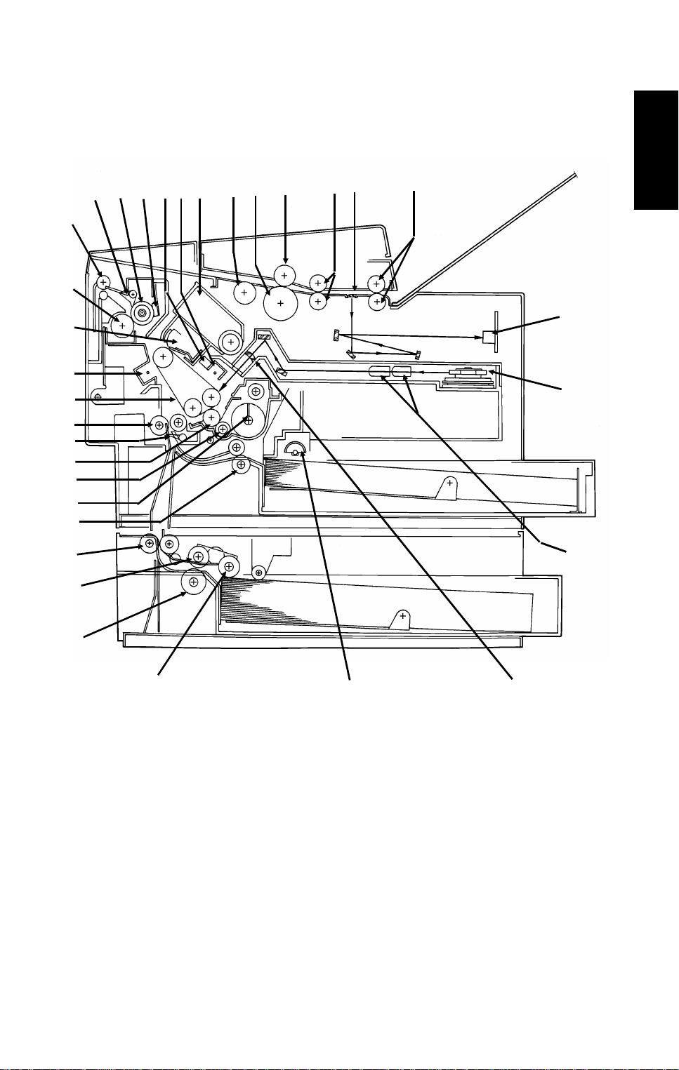
OVERALL MACHINE INFORMATION November 30th, 1991
COMPONENT LAYOUT
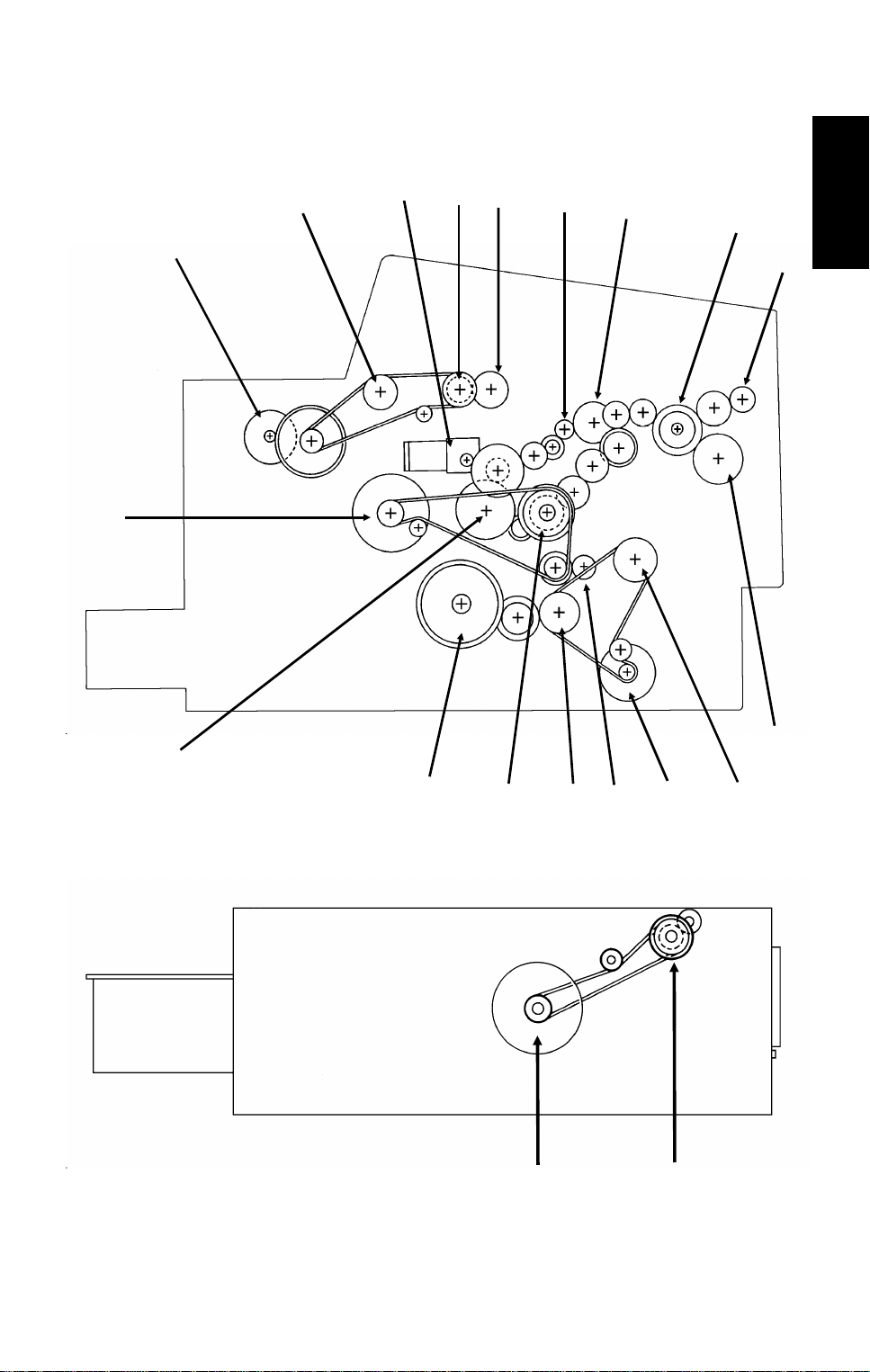
1.3. COMPONENT LAY OUT
1.3.1. Mechanical Components
45
14
15
16
17
18
19
20
21
22
23
13
12
11
10
6789
1
2
3
1
32
31
24
25
26
27
1. R2 Rollers Feed the document through the scanner.
2. Exposure Glass Exposes the original to light from the xenon lamp.
3. R1 Rollers Feed the document through the scanner.
4. Separation Roller Allows one page into the scanner.
5. Document Feed Roller Feeds the document into the scanner.
6. Pick-up Roller Picks up pages of the document from the document
table.
7. Toner Cartridge This supplies toner to the development unit. It is part of
the CTM (Cleaning/Toner Magazine).
8. Charge Corona Unit This applies a charge to the master at the start of the
print cycle.
9. Quenching Lamp This removes excess charge from the master at the end
of the print cycle.
10. Thermistor This measures the temperature in the fusing unit.
11. Hot Roller Heat from this roller fuses the toner to the copy paper.
28
29
30
1-5
Page 8

November 30th, 1991 OVERALL MACHINE INFORMATION
COMPONENT LAYOUT
12. Hot Roller Strippers These take the paper off the hot roller after fusing.
13. Copy Feed-out Rollers These feed the paper out of the printer.
14. Pressure Roller (Fusing) This applies pressure to the paper during the fusing
process.
15. Cleaning Unit/Used Toner
Tank
16. Transfer Corona Unit This applies a charge to the paper to pull the toner off
17. Master Belt Also known as the CS (Compact Seamless) Engine.
18. Registration Roller This carries out the registration process.
19. Registration Sensor This detects when paper is approaching the registration
20. Development Roller This roller applies toner to the latent image on the
21. Toner Supply Bar This feeds toner to the development roller.
22. Toner Mixing Bar This stirs up the toner in the development unit, so that it
23. Upper Relay Rollers These feed paper from the upper cassette into the
24. Lower Relay Rollers These feed paper from the lower cassette into the
25. Lower Paper Feed Roller This feeds paper out of the lower cassette.
26. Lower Paper Separation
Roller
27. Lower Paper Pick-up
Roller
28. Upper Paper Feed Rollers These pick up the top sheet of paper from the stack in
29. Focusing Lens This focuses the laser beam onto the master belt.
30.
Fθ Lenses
31. Hexagonal Mirror This passes the laser beam across the master belt.
32. CCD (Charge Coupled
Device)
This removes excess toner from the master after image
transfer and stores it. It is part of the CTM
(Cleaning/Toner Magazine).
the master and onto the copy paper.
The latent image is written to this organic
photoconductor belt.
roller.
master belt.
does not collect into lumps.
printer.
printer.
This ensures that only one sheet of paper at a time
leaves the lower cassette.
This picks up the top sheet of paper from the stack in
the lower cassette and passes it to the feed roller.
the upper cassette and feed it into the printer.
These ensure that the thickness of the laser beam is
uniform across the main scan.
This converts the light reflected from the document into
an analog video signal.
1-6
Page 9
567
13
14
15
OVERALL MACHINE INFORMATION November 30th, 1991
COMPONENT LAYOUT
1.3.2. Drive Components
18
2
1
3
4
8
1
9
17
16
19
12
20
10
11
1-7
Page 10

November 30th, 1991 OVERALL MACHINE INFORMATION
COMPONENT LAYOUT
1. Tx Motor This stepper motor drives the scanner.
2. R2 Roller This feeds the original through the scanner.
3. Toner Supply Motor This dc motor drives the toner supply mechanism.
4. R1 Roller This feeds the original through the scanner.
5. Shutter Drive Gear This ensures that the shutter moves out of the
document feed path at the correct time.
6. Toner Supply Gear (CTM) This ensures the supply of toner from the CTM into the
development unit. It is part of the CTM.
7. Cleaning Brush Drive Gear This drives the cleaning brush in the CTM.
8. Hot Roller This fuses the toner to the copy paper.
9. Copy Feed-out Roller This feeds printouts out of the machine.
10. Pressure Roller This applies pressure to the copy paper in the fusing
unit.
11. Registration Roller Drive
Gear
12. Upper Paper Feed Motor This drives the paper feed mechanism in the upper
13. Development Roller Drive
Gear
14. Upper Paper Feed Roller
Drive Gear
15. Master Belt Drive Gear This drives the master belt.
16. Paper Feed Clutch This transfers drive from the upper paper feed motor to
17. Toner Supply Gear
(Development)
18. Main Motor This brushless dc motor drives the master belt, fusing
19. Lower Paper Feed Motor This drives the paper feed mechanism in the lower
20. Lower Paper Feed Clutch This transfers drive from the lower paper feed motor to
This drives the registration roller.
cassette.
This drives the development roller.
This drives the upper paper feed roller.
the upper paper feed mechanism.
This ensures the collection of toner from the CTM, and
its distribution across the full length of the development
unit.
unit, development unit, and cleaning unit.
cassette.
the lower paper feed mechanism.
1-8
Page 11
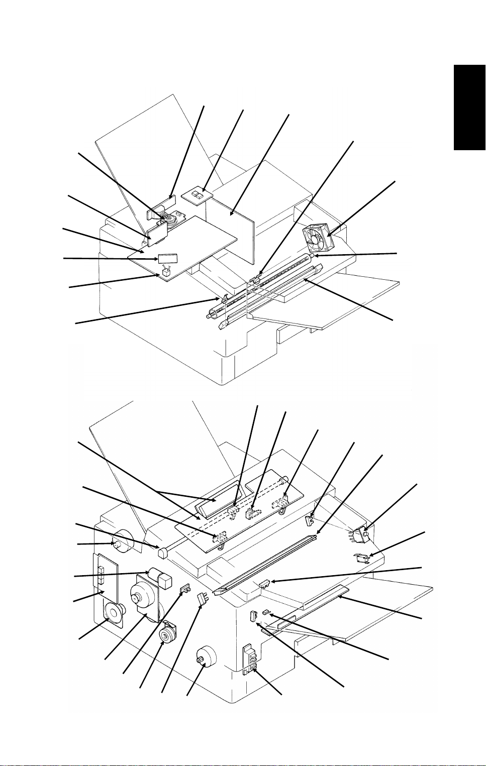
16
24
9
12
OVERALL MACHINE INFORMATION November 30th, 1991
COMPONENT LAYOUT
1.3.3. Electrical Components
11
10
13
8
1
2
3
4
5
6
7
1
34
33
32
37
35
36
31
30
29
28
27
26
14
14
15
15
25
17
18
19
20
21
22
23
1-9
Page 12
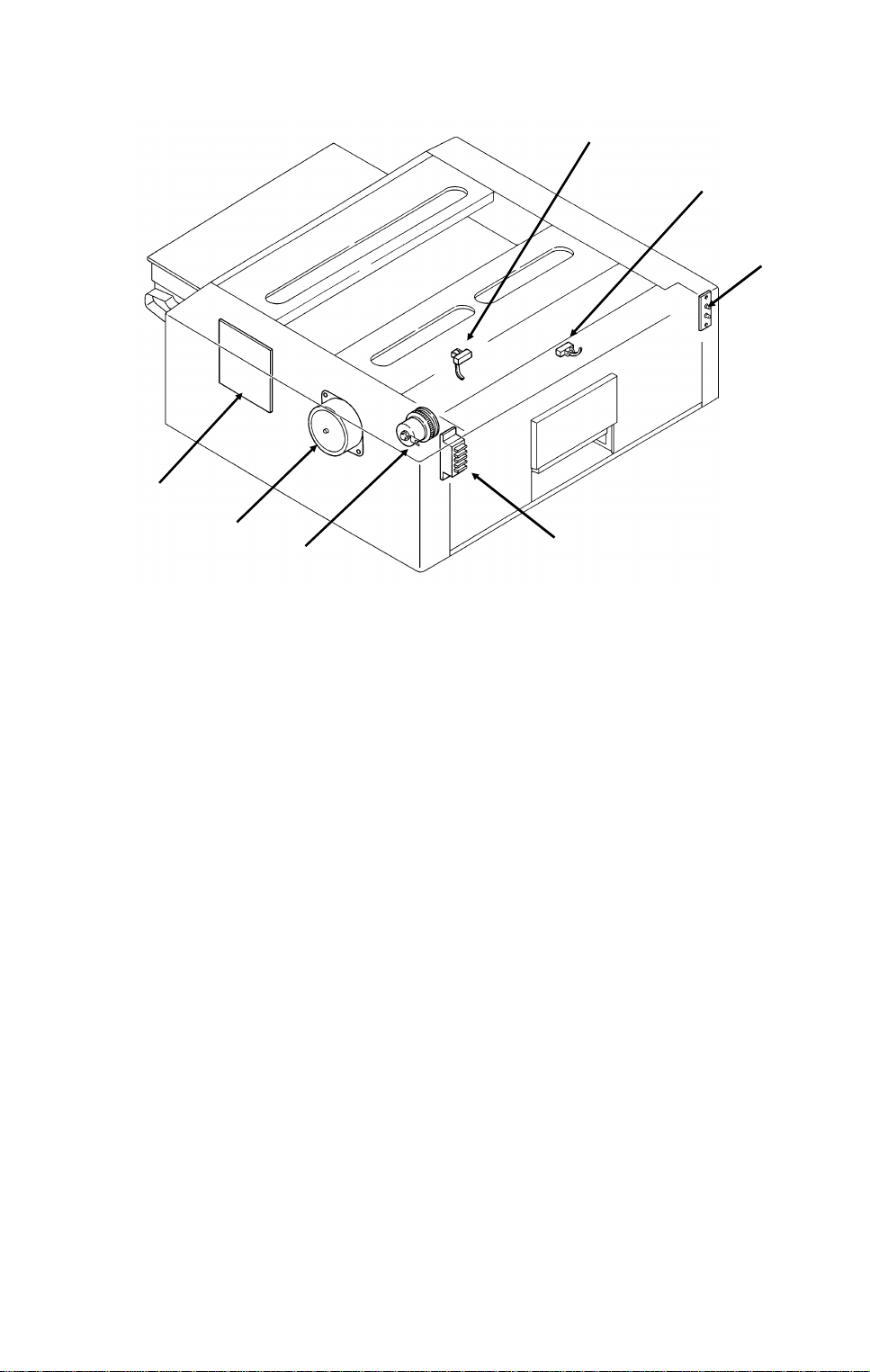
November 30th, 1991 OVERALL MACHINE INFORMATION
COMPONENT LAYOUT
Lower Cassette
44
43
42
Name Description No.
PCBs
FCU This board controls the machine. 11
MBU This board contains the system ROM and RAM for storing
system parameters such as bit switch settings and programmed
telephone numbers.
SBU This board contains the CCD. 1
OP-PORT This board controls the operation panel. 37
NCU This board contains relays and switches for interfacing the
machine to the network and the handset.
PSU This board supplies power to the machine. 3
LD Unit This board drives the laser diode. 10
PFU This board controls the lower paper feed unit. 44
MOTORS
Tx Motor This stepper motor drives the scanner. 34
Main Motor This dc motor drives the fusing unit, master belt, development
roller, and cleaning unit.
Upper Paper
Feed Motor
Lower Paper
Feed Motor
Toner Supply Mo-
tor
Hexagonal Mirror
Motor
Ozone Fan This removes ozone-laden air from the vicinity of the master
This stepper motor drives the upper paper feed mechanism and
the registration roller.
This stepper motor drives the lower paper feed mechanism. 43
This dc motor drives the toner supply mechanism. 33
This high-speed dc motor drives the hexagonal mirror in the
laser printer optics.
unit, and filters out the ozone.
38
39
40
41
12
32
30
26
13
5
1-10
Page 13

OVERALL MACHINE INFORMATION November 30th, 1991
COMPONENT LAYOUT
Name Description No.
CLUTCHES
Upper Paper
Feed Clutch
Lower Paper
Feed Clutch
SENSORS
Document Sensor This detects the presence of a document in the feeder. 36
Scan Line Sensor This detects when a page is approaching the auto shading
Document Width
Sensor
Toner Near-end
Sensor
Upper Paper
Size Detector
Upper Paper End
Sensor
Registration Sensor
Paper Feed-out
Sensor
Front Cover
Switch
CTM Sensor This detects when a CTM has been installed in the machine. 27
Lower Paper
Size Detector
Lower Paper End
Sensor
Lower Paper
Feed Sensor
INTERLOCK SWITCHES
Front Cover Interlock Switches
OTHERS
Speaker This allows the user to listen to the condition of the telephone
Xenon Lamp This lamp illuminates the document. 35
Xenon Lamp
Driver
Charge Corona
and Quenching
Lamp Unit
Transfer Corona
Unit
Varistor This ensures that the charge given to the master by the charge
Marker This stamps a red circle on each page that is successfully fed
This transfers drive from the upper paper feed motor to the
paper feed roller in the upper cassette.
This transfers drive from the lower paper feed motor to the
paper feed roller in the lower cassette.
position.
This detects when a B4-width [10.1"] document has been
placed in the feeder.
This detects when the toner has almost run out. 17
This detects the paper size installed in the upper cassette. The
user must install the correct actuator.
This detects when the paper in the upper cassette has run out. 29
This detects when paper has arrived at the registration rollers. 21
This detects when the paper has been fed out of the printer. 24
This detects whether the front cover is open or closed. 23
This detects the paper size installed in the lower cassette. The
user must install the correct actuator.
This detects when the paper in the lower cassette has run out. 38
This sensor detects the presence of paper at the lower paper
feed roller.
If the front cover is open, these interlock switches interrupt the
+5VLD power supply for the laser diode and the +24VD power
supply for the power pack, motors, and other components.
line.
This drives the xenon lamp. 2
The charge corona unit charges the master belt at the start of
the print cycle. The quenching lamp removes excess charge
from the master belt at the end of the print cycle.
This pulls the toner off the master and onto the copy paper. 7
corona wire does not exceed -750 Volts.
through the scanner.
28
42
14
16
25
41
39
19,
20
31
18
9
15
1
1-11
Page 14

November 30th, 1991 OVERALL MACHINE INFORMATION
COMPONENT LAYOUT
Name Description No.
Power Pack This supplies high voltages to the corona wires and the
development bias terminal.
Fusing Lamp This fuses the toner to the paper. 6
Thermistor This monitors the temperature inside the fusing unit. 8
Thermostat This interrupts the ac power supply to the fusing lamp if the
temperature exceeds 400 °C.
Lower Cassette
Indicator Panel
This contains indicators to show the status of the lower cassette. 40
22
4
1-12
Page 15
OVERALL MACHINE INFORMATION November 30th, 1991
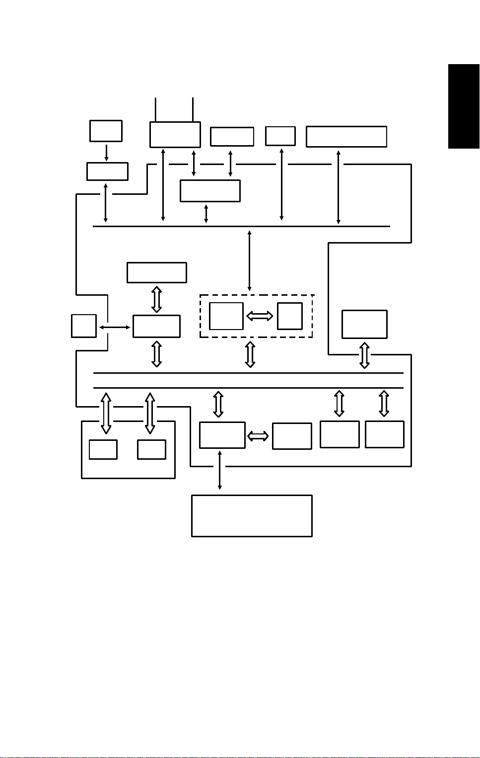
OVERALL MACHINE CONTROL
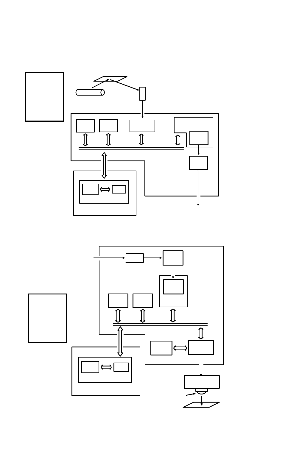
1.4. OVERALL MACHINE CONTROL
SBU
(CCD)
Scanner
Sensors
Operation
Panel
NCU
CONTROL SIGNALS
Video Processing
Memory
Video
Processor
HandsetLine
Speaker
Modem AFE
CPU
PSU
Port
1
Scanner and Printer Drive
Components and Sensors
FCU
I/O
RS-232C
Interface
DATA AND ADDRESS BUS
ECM
Memory
MBU
Laser
Interface
RAMROM
Laser Diode Driver
Main Scan Start Detector
Interlock Switch
Page
Memory
SAF
Memory
The cpu on the FCU board controls the machine, as shown in the above
drawing.
There is no modem board in the machine. The cpu performs the digital functions of a modem and carries out digital to analog conversion of facsimile
data. There is a separa te an alog modem chip, called the Modem AFE, wh ich
does the rest of the modem operations.
1-13
Page 16
November 30th, 1991 OVERALL MACHINE INFORMATION
VIDEO DATA PATH
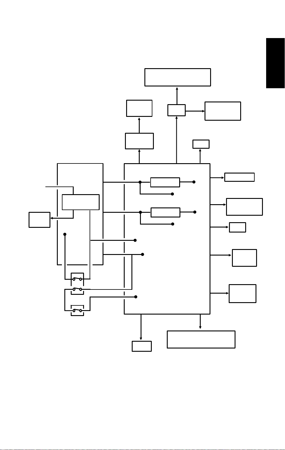
1.5. VIDEO DATA PATH
1.5.1. Transmission
Original
Reference:
Group 3
Facsimile
Manual,
section
1-3-1
Xenon
Lamp
ECM
Memory
Line
Buffer
SAF
Memory
RAM
MBU
FIFO
Video
Processor
The following diagrams show
the data path for this mod el.
CCD
Analog Signal
CPU
Modem
(Digital)
MODEM
AFE
FCU
Modem
(Analog)
To the
Network
(via the NCU)
1.5.2. Reception
From the
Network
(via the NCU)
Reference:
Group 3
Facsimile
Manual,
section
1-3-2
Line
Buffer
RAM
MBU
FCU
Memory
SAF
FIFO
Filter
HYBRID IC
Memory
ECM
Page
Memory
Laser Diode
Modem
(Analog)
Modem
(Digital)
CPU
MODEM
AFE
Laser
Interface
Laser Diode
Driver
1-14
Copy Paper
Page 17
OVERALL MACHINE INFORMATION November 30th, 1991
POWER DISTRIBUTION
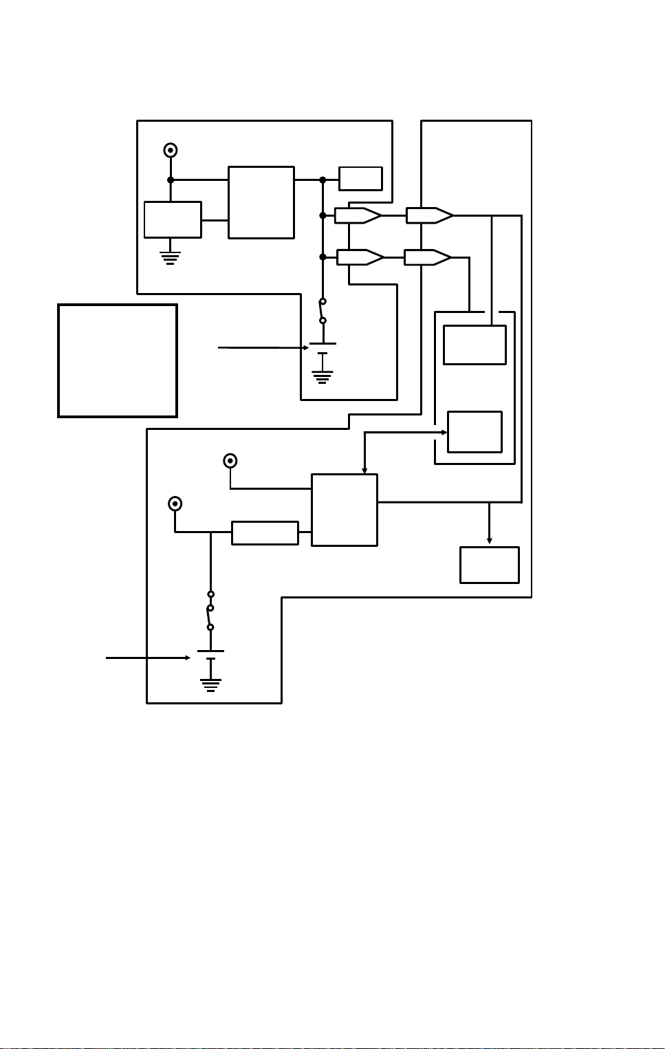
1.6. POWER DISTRI BUTI O N
1.6.1. Distribution Diagram
AC Main
PSU
Power
AC Switching
Circuit
Fusing
Lamp
+24V
-12V
+24VS
+24VD
Scanner
Sensors
+5V
Operation
Panel
+5V
+24VD
Lower Paper Feed Motor
Lower Paper Feed Clutch
+24VD
PFU
+5V
+24VD
+5V
NCU
+5V
+24VS
FCU
Regulator
- 5V
- 12V
+12V
Regulator
+24VS
1
Sensors and
Indicators
FUSING UNIT
Thermistor
+5V
+5V
MBU
SAF Memory
+5V
SBU
+12V
+5V
+5V
Front Cover
Interlock Switch
Front Cover
Microswitch
+5V
+5V
+5VLD
+5VLD
LDDR
Laser Diode
+24VD
Motors, Clutches, Lamps,
Marker, Power Pack
The laser diode is powered by a special +5V supply, called +5VLD.
There are two +24V power supplies:
• +24VS: This is always on when the main switch is o n.
• +24VD: This is interrupte d if th e fro nt cover interlock switch opens.
There is no +24VD activation signa l from th e cpu to the PS U.
Printer
Sensors
RS-232C
Interface
1-15
Page 18
November 30th, 1991 OVERALL MACHINE INFORMATION
POWER DISTRIBUTION
1.6.2. Memory Back-up Circuit
Reference:
Group 3
Facsimile
Manual, section
1-4-3, Circuit
type 1
+5V
Voltage
Detector
+24V
[A]
+5V
Switching
Circuit
Regulator
MBU
RAM
1-11
1-9
Battery
Switch
Battery
Switching
Circuit
FCU
17-11
17-9
Real Time
Clock
CPU
Memory
Monitor
SAF
Memory
Battery
Switch
[B]
Battery
The battery [A] on the MBU backs up the RA M on the MBU, which con ta ins
system parameters. It also backs up the rea l time clock in t he cpu . This battery is not rechargeable. CN1-9 te lls the cpu whe th er back-up power (CN1-
11) comes from the battery or the +5V power supply.
A rechargeable battery [B ] on the FCU board backs up the SAF memo ry and
the real time clock for 1 hour. While the main power is on, the +24V supply recharges the battery.
If there is data in the SAF memory, the rechargeable ba tt ery [B ] also backs
up the real time clock, to preserve the MBU battery.
1-16
Page 19
[A]
DETAILED SECTION DESCRIPTIONS November 30th, 1991 SCANNER
2. DETAILED SECTION DESCRIPTIONS
2.1. SCANNER
2.1.1. Mechanisms
1. Document Detection
Document Table
Reference:
Group 3
Facsimile
Manual,
section 2-1-1.
2
• The scanner is B4-width [1 0. 1" ], with a B4 document width de te ctor [A].
The scanner can feed paper up to 304 mm [1 2"] wide. However, only
10.1" of this width will be scanned. The ext ra width allows users to feed
wide originals with wide margins, such as computer form printouts.
• The scanner contains a xenon lamp.
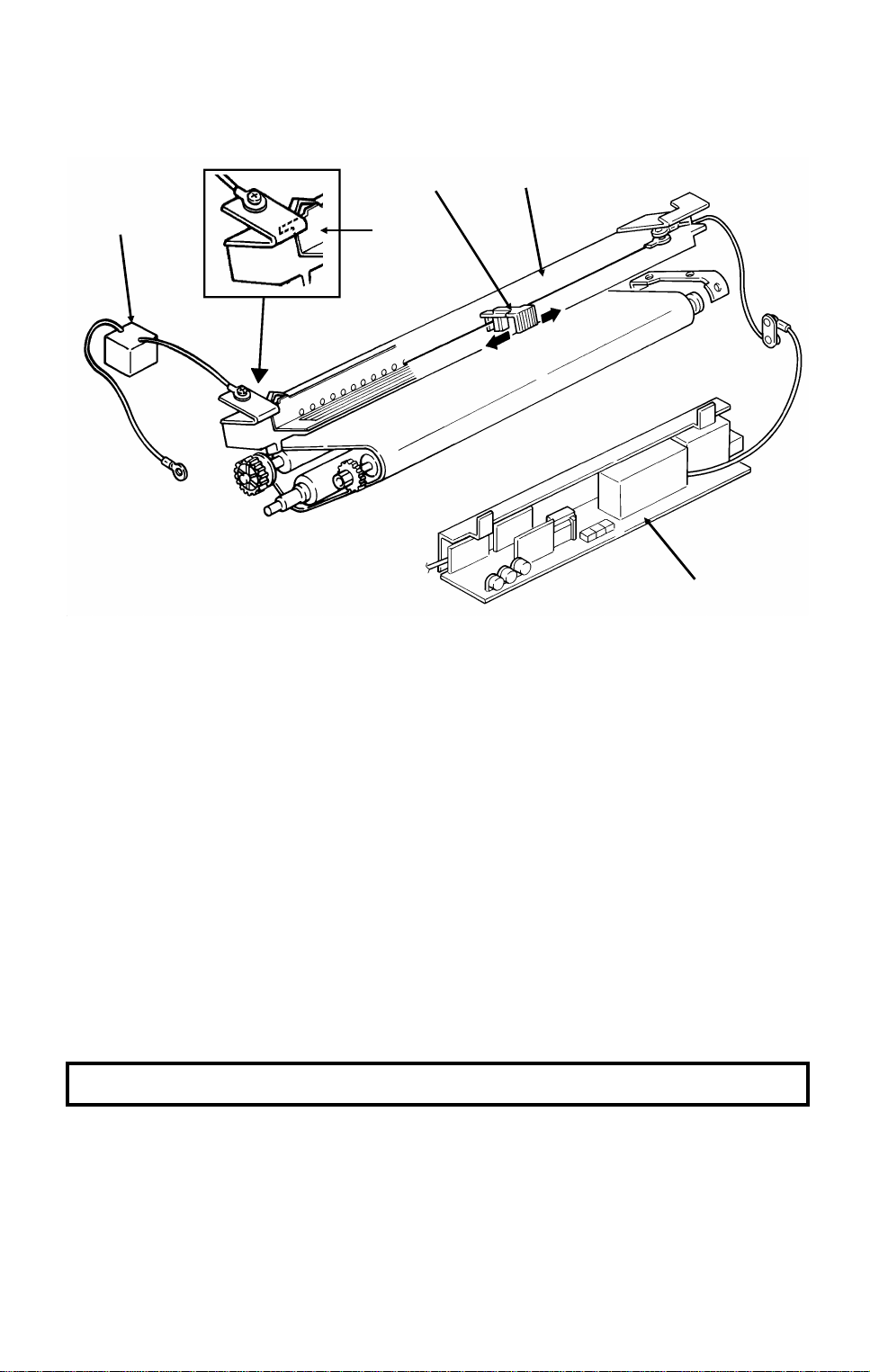
• There is a fold-down extension [B] to support long documents.
[B]
2-1
Page 20
[A]
Reference:
Group 3
Facsimile
Manual,
section 2-1-1.
November 30th, 1991 DETAILED SECTION DESCRIPTIONS
SCANNER
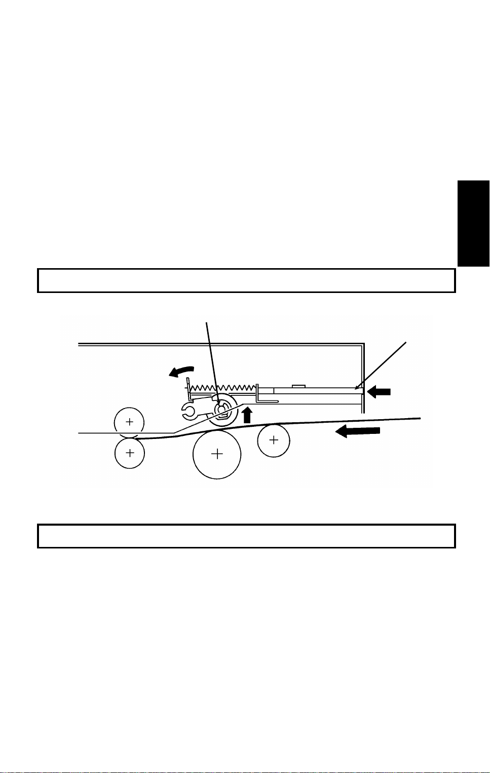
Shutter
[C]
[B]
In standby mode, tab [A] rests on cam [B] . Whe n the tx mot or starts, the motor rotates forwards (white arrows), the cam lifts the tab, and the shut ter [C]
rises. After the last pa ge ha s be en fed through the scanner, the tx motor reverses (black arrows), the cam drops back to the standb y posit ion, and the
shutter blocks the scan ne r p at h again.
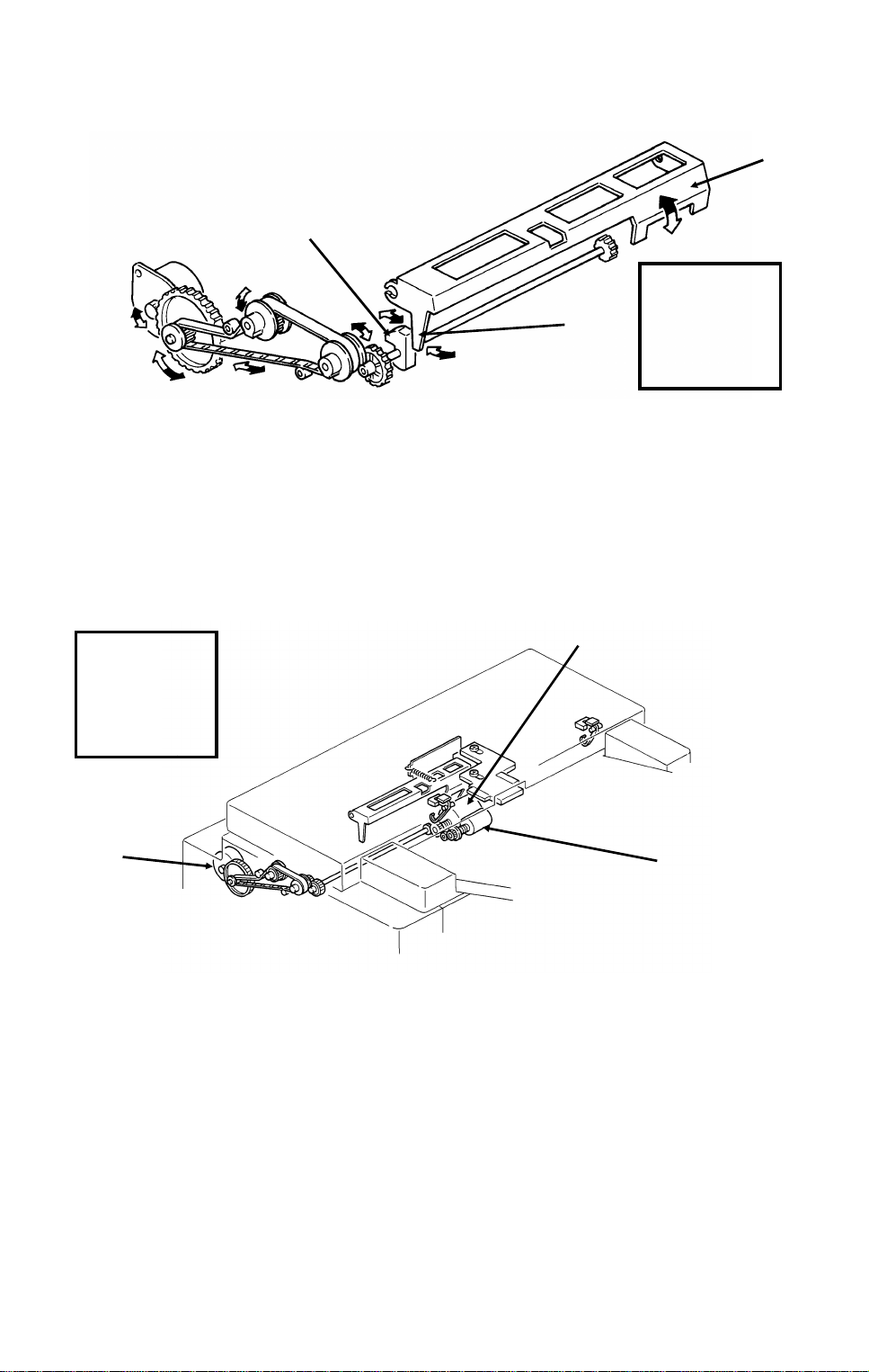
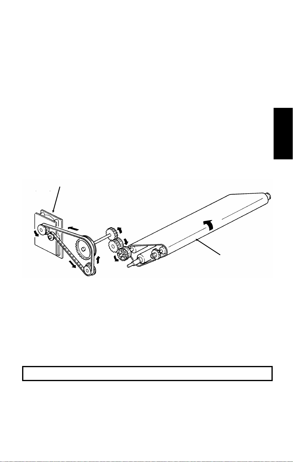
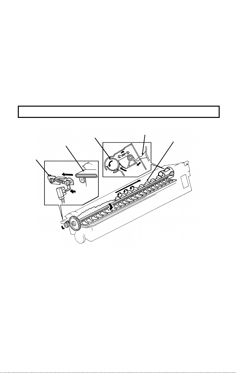
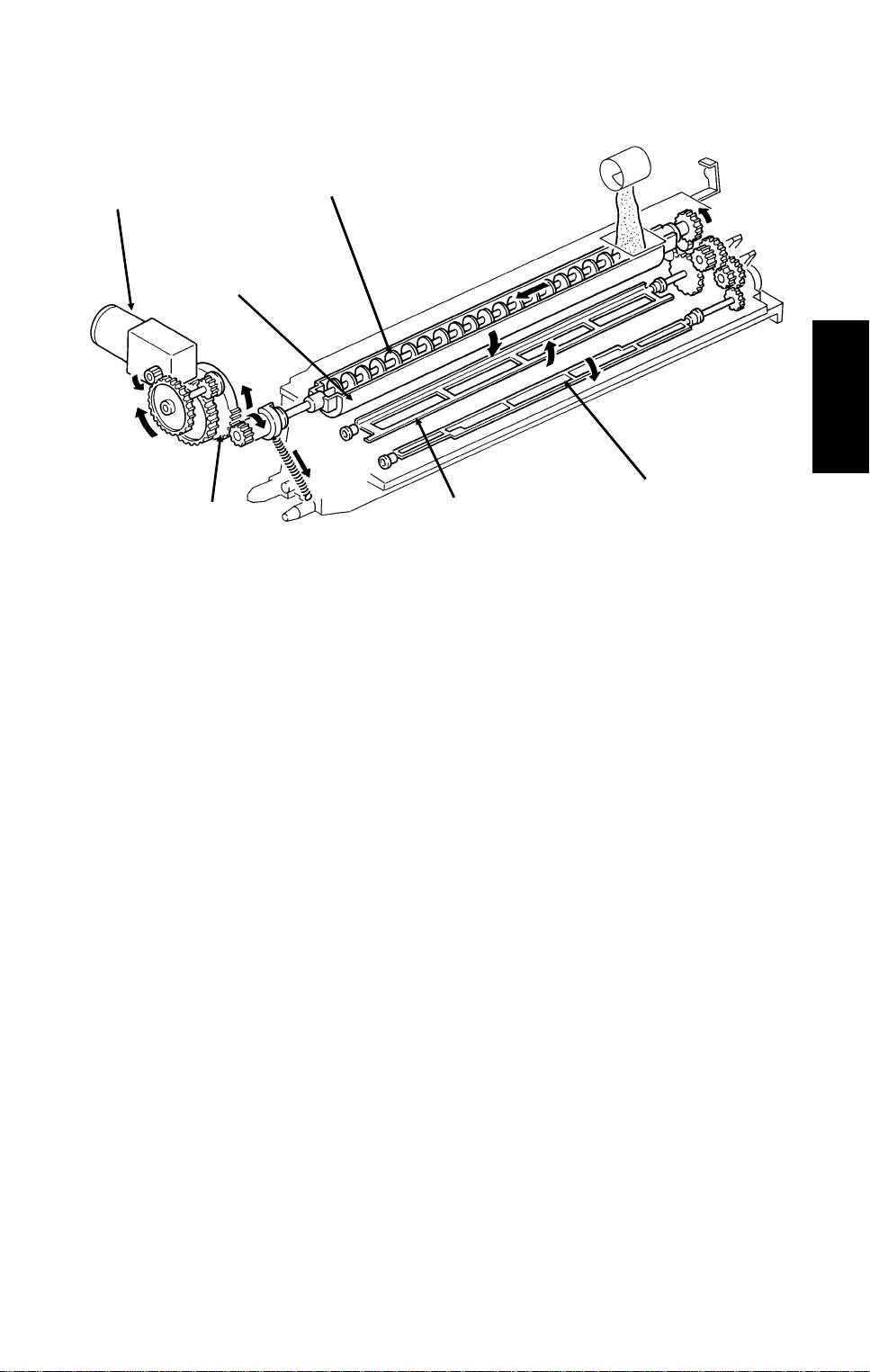
2. Pick-up and Feed
Drive Mechanism
Reference:
Group 3
Facsimile
Manual,
section 2-2-1.
[A]
[B]
[C]
This machine has a Mechanical Clu tch Mecha nism. The tx motor [A] drives
the feed roller [B] and pick-up roller [C].
Resolution
Standard - The tx motor feeds the document at 7.7 lines/mm. The video processor executes
OR processing to convert the data into 3.85 lines/mm.
Detail - The tx motor feeds the document at 7.7 lines/mm. There is no OR processing, and
the data is transmitted at 7.7 lines/mm.
Fine - The tx motor feeds the document and transmits data at 15.4 lines/mm. If the other terminal cannot receive at this resolution, alternate lines of data are deleted, so the effective
resolution of the transmitted data is 7.7 lines/mm.
2-2
Page 21
DETAILED SECTION DESCRIPTIONS November 30th, 1991
SCANNER
Jam Conditions
The cpu detects a document jam if one of the following cond itions occurs.
• The scan line sensor does no t switch on with in 9 s of the Start key be-
ing pressed.
• The scan line sensor does no t tu rn off after the maximum document
length has been fe d since it turned on.
• The scan line sensor switch es on wh ile th e do cument sensor is off.
• The document width sensor switches on while the document sen sor is
off.
• The scan line sensor does no t tu rn on wit hin 5 s of the end of sta mpin g,
if the document senso r is on.
Separation
Reference: Group 3 Facsimile Manual, section 2-2-2.
2
3. Manual Feed
The manual feed butt on [A] lif ts th e separation roller [B] out of the document
feed path. There is no manual fe ed switch.
Reference: Group 3 Facsimile Manual, section 2-2-3.
[B]
[A]
2-3
Page 22
November 30th, 1991 DETAILED SECTION DESCRIPTIONS
SCANNER
2.1.2. Video Data Proces si ng
Output from the CCD
A
Auto Shading
Memory
WHITE
WAVEFORM
FEEDBACK
Reference:
Group 3
Facsimile
Manual,
section 2-3
DC
Filter
VIDEO
PROCESSOR
Corrected Data from the Auto Shading Circuit
Amplifier
Gamma
Correction,
MTF
A/D
Converter
Data Processing
Circuits
Halftone
Process
Edge
Detection
To the CPU
and Modem
Basic
EDGE
ELEMENTS
Peak
Hold
CORRECTED
DATA
Error
Diffusion
Halftone
Process
Comparator
Background
Detection
OR
Processing
Reduction
A
NON-EDGE
ELEMENTS
Reduction
Halftone
B
Process Selector
To CPU and Modem
2-4
Image/Text
Detection
B’
Page 23
DETAILED SECTION DESCRIPTIONS November 30th, 1991
PRINTER
2.2. PRINTER
2.2.1. Mechanisms
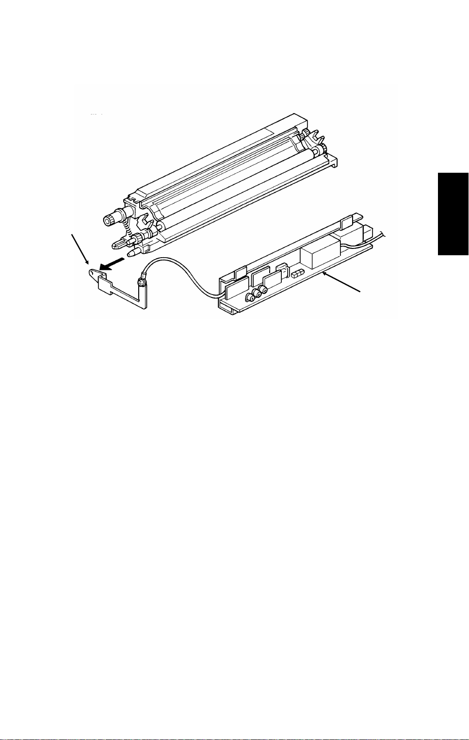
1. Master Unit
This printer uses a "write to black" syste m, usin g ne ga tive ton er.
The master unit contains a durable OPC master belt. The expe cte d lif et ime o f
each master unit is about 60 ,000 copies (this is the target value). Because of
this long lifetime, the user is not exp ect ed to cha nge th e mast er; the re is no
Replace Master indicator.
The master belt does not have a bond seam, so no mast er ho me position detection is needed. There is also no ma ste r unit in terlock switch; there is an interlock switch on the front cover.
[A]
2
[B]
The main motor [A] drives the master belt [B].
• At the start of printing , it turns on briefly and the master belt moves un -
der the quenching lamp to ensure that it is fully discharged.
• Then, when the fu sing la mp is at th e correct temperature and the page
memory contains a complete page of da ta, and the hexagonal mirror
motor is running at the correct speed , the main mo tor swit che s on again.
• When the main motor is runn ing at th e correct speed, the laser diode
turns on for automatic power control.
Reference: Group 3 Facsimile Manual, section 4-1
2-5
Page 24
November 30th, 1991 DETAILED SECTION DESCRIPTIONS
PRINTER
2. Charge Corona Unit
[A]
[C]
[B]
[D]
[E]
The charge corona un it [A ] gives a -750 V charge to the ma ster belt. The
varistor [B] ensures th at the charge does not exceed this valu e.
The connection between the powe r p ack [C] and the coron a unit is n ot broken when the front cover is o pene d. Ho weve r, the front cover interlock swit ch
cuts the +24V power line to the power pack if the cover is o pene d.
The charge corona un it con tains a wire cleaner [D].
The charge corona switch es on at th e same time as the laser diode starts its
power control procedure.
There is one ozone fan on the right hand side of the machine. It sucks air out
of the machine thro ugh the ozone filter, which is part of the ozone fan assembly. The ozone fan switches on when a ringing signal is detecte d, an d st ays
on until the fusing lamp te mperature falls back below 130 °C at the end of the
printing run.
The inset shows how the grid plate [E] connects to the varistor.
Reference: Group 3 Facsimile Manual, section 4-2
2-6
Page 25

DETAILED SECTION DESCRIPTIONS November 30th, 1991
PRINTER
3. Laser Optics
[E]
[F]
[B]
[D]
[A]
[C]
2
The optics are the same as those illu stra ted in section 4-3-3 of the Group 3
Facsimile Manual, except that th ere are two mirrors [A] at the "Second Mirro r"
position.
Other points to note are as follows:
• The focusing lens [B] is a barrel toroidal lens.
• The shield glass [C] preven ts toner from entering the laser optics are a,
and may need cleaning occasionally.
• An optical fibre [D] passes the ref lected laser beam to the main scan
start detector [E]. This detector is situat ed on the laser d iod e drive b oa rd
[F], unlike shown in the diagram.
• The strength of th e beam is 0 .4 36 mW at a wavelength of 780 nm.
• The dimensions of the dot on th e mast er be lt are 65 µm (main scan di-
rection) by 75 µm (sub-scan direction).
The charge on the exposed parts of the belt drop s to abou t -15 0 V, while nonexposed areas remain at abou t -750 V.
The laser engine characte ristics are as follows (refer to page 4-3-21 of the
Group 3 Facsimile manual for backg rou nd ).
• Motor speed: 9,240 rpm
• Motor type: Hexagonal
• LD clock frequency: 5.3311 MHz
• Time betwee n main scan synchronization signa ls: 1. 08 2 ms
• Number of dots pe r ma in scan: 5769
2-7
Page 26
[A]
November 30th, 1991 DETAILED SECTION DESCRIPTIONS
PRINTER
4. Development
Overview
This machine uses a ’write-to-b lack’ development system using negative
toner.
The toner cassette is part of a dispo sable unit known as the CTM (Cleaning/Toner Magazine). The CTM contains a toner cassette, toner supply
mechanism, cleaning unit , an d used to ner t ank. When the toner is all used
up, the CTM is replaced.
Reference: Group 3 facsimile Manual, section 4-4
Toner Supply
[B]
[C]
[D]
[E]
When a new CTM is installed in the machine and the front cover is closed,
the main motor and to ne r su pp ly mo to r t urn on. When the front cover is
closed, a tab [A] o n the fusing unit cover forces the hopper [B] t o ope n. Also,
tab [C] on the CTM pushes bracket [D], which mo ves th e CTM sensor actuator into the sensor.
Continued on the next page
2-8
Page 27
DETAILED SECTION DESCRIPTIONS November 30th, 1991
PRINTER
[F]
[H]
[I] [J]
The toner supply motor [F] drive s the ton er sup ply sha ft ([E] in the diagram
on the previous page). This spiral shaft feeds toner to the ho pper.
Inside the development unit is another spiral shaft [G]. This shaft, d riven by
the main motor, distributes toner across the length of trough [H]. The toner
supply motor drives gear [I], and once every rot at ion , it tips the trough upside
down, dropping t he toner into the develo pment unit. A sprin g immediately
pulls the trough back upright so that it can cont inu e to receive ton er.
[G]
[K]
2
The toner mixing bar [J], driven by the main motor, keeps the toner agitated
as it builds up at the botto m of th e de velopment unit. The toner supply bar [K]
supplies toner to the de velo pment roller.
While toner is being supplied, th e main motor is also operating the toner nearend detection mecha nism. When a fresh toner cassett e is installed, the sensor detects toner near-end, because there is not much ton e r in th e
development unit. Wh en some to ne r has be en transferred, the signal from
the toner near-end senso r ret urns to normal. About 22 s aft er t ha t, th e ton er
supply motor stops and no more toner is transferred into the development
unit.
During printing, if toner near-en d is detect ed , the tone r supply mechanism will
start up again. Toner will be supplied until t he sensor signal returns to normal.
If the toner cassette in the CTM is empty, no toner will be transferred, and th e
sensor signal will not return to normal. If the sen sor ou tp ut s the nea r-en d signal for more than 5 minu te s, t he cpu blinks the Add Ton er indicator. See
"Toner Near-end Detection" for more details.
2-9
Page 28
November 30th, 1991 DETAILED SECTION DESCRIPTIONS
PRINTER
Development Unit Drive
[A]
[B]
During printing, drive from th e main moto r at gear [A] drives the development
roller [B]. The main moto r a lso drive s the master belt, so the developme nt
roller and the master belt always move at the same time; there fo re, no development clutch is needed.
Toner Near-end Detection
The toner near-end de te ction mechanism is exactly the same as described in
section 4-4-4 of the Grou p 3 Facsimile Manu al. The sensor signal is as
shown in the following diagram.
Reference:
Group 3
Facsimile
Manual,
section 4-4-4.
1.9 s
0.1 ms
The cpu starts to blink the Add Toner indicator under the follo wing conditions:
• At power up: If the sensor ou tp ut indicates toner near-e nd for 6 s
• During printing: If the senso r o ut pu t ind icates toner near-end fo r more
than 5 minutes, totalled over consecutive print runs (when the motor
stops, the sensor mechanism is deactivated, so time between printing
runs does not count towards the 5 minute time limit)
After 100 more pages ha ve b een p rint ed , t he Ad d Toner indicator remains lit,
and printing is disabled until a new CTM has bee n added.
2-10
Page 29
DETAILED SECTION DESCRIPTIONS November 30th, 1991
PRINTER
Development Bias
[B]
[A]
2
The development bias and switch ing bias are supp lied from th e po wer pa ck
[A] at the same terminal [B].
• Development bias: - 530 ± 20 Vdc (BIASL)
• Switching bias: +70 ± 20 Vdc (BIASH)
The switching bias is used at the following times:
• Between pages of a prin t run , while the development bia s is off
• While toner is being transfe rred from the CTM to the development unit
2-11
Page 30
November 30th, 1991 DETAILED SECTION DESCRIPTIONS
PRINTER
5. Paper Feed
There are two cassette s, a 25 0-sh ee t cassette, and an optional 500-sheet
cassette.
The sizes of paper that the cassettes can take are listed in the specifications
(section 1-1).
[A]
Paper feeds from the rear towards the front . The lower paper feed path
bends upward through the front part of the upper cassette. The two paper
feed paths merge just before the registratio n rolle r [A] .
2-12
Page 31

[B]
[B]
DETAILED SECTION DESCRIPTIONS November 30th, 1991
PRINTER
Paper Lift
Standard Cassette
[C]
[A]
A mechanical paper lift mecha nism is used. When the user places the cassette into the machine, a pin [A] in the base of the cassette act ivates a spring
loaded lever mechanism [B], which force s up th e pa per lif t arm [C] until t he
top of the stack touches the paper height positioner.
Lower Cassette
[A]
[C]
[E]
2
[D]
A mechanical paper lift mecha nism is used. When the user places the cassette into the machine, a tab [A] on the rear of the cassette push es a plate [B]
towards the rear of th e machine as the user slides in the ca ssette. This plate,
driven by a spring [C], forces up the pa per lif t arm [D] . Th e p ap er h eig ht positioner [E] ensures tha t the paper is not pushed up too far.
Reference: Group 3 Facsimile Manual, section 4-5-2.
2-13
Page 32

November 30th, 1991 DETAILED SECTION DESCRIPTIONS
PRINTER
Pick-up and Feed Mechanism
Standard Cassette (Clutch Driven Single Roller Mechanism)
Reference:
Group 3
Facsimile
Manual,
section 4-5-3.
[B]
[D]
[G]
[C]
[A]
[E] [F]
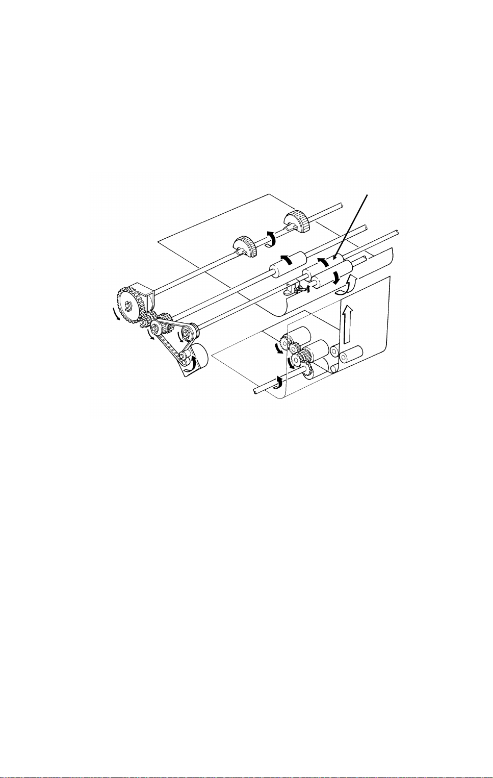
The upper paper feed moto r [ A] drives th e pick-up and feed mechanism. The
paper feed clutch [B] transfers drive fro m this motor to the feed rollers [C].
When the paper feed clutch turns on, a metal plate [D] moves away from
gear [E]. A pin [F] on this plate releases the gear, and the paper feed roller
turns. However, the clutch switches off after only 0.3 s, and a spring forces
the plate back to th e starting position. After one revolutio n, the rib [G] on the
inside of the gear comes aga inst the pin, and the paper feed roller stops.
When the page memory is full, the upper paper f ee d moto r tu rns on. At th e
beginning, it rotates at a slower speed (202.5 pps) to avoid excessive start -up
noise and start-up current peak.
At 0.1 s after the main moto r re ach es the correct speed, the motor turns at a
higher speed (405 pps). This higher speed, used for pick-up and feed, ensures that time is not wast ed getting paper into the printer. At the same time,
the upper paper feed clutch turns on and paper is fed into the printer.
Shortly after the registrat ion sensor turns on, the main motor has the lead ing
edge of the paper, so the upper paper feed motor rotates at 202.5 pps again
to match the feed speed of the main motor.
When the trailing edge of the paper has left the registratio n sen sor, the paper
is no longer affected by the upper paper fe ed mo tor. The upper p aper feed
motor goes back to 405 pps ready for feeding the next page.
2-14
Page 33

DETAILED SECTION DESCRIPTIONS November 30th, 1991
PRINTER
Lower Cassette (Clutch Driven Two Roller Mechanism)
Reference:
Group 3
Facsimile
Manual,
section 4-5-3.
[A]
[C]
[D]
[E]
2
[B]
The lower paper feed motor [A] drives the lower paper feed mecha nism, and
the lower paper feed clutch [B] tra nsfers drive from the motor to the lower
pick-up [C] and feed [D] rollers at the correct time.
When the page memory is full, the lower paper feed mot or t urn s on. A t t he be ginning, it rotates at a slower spe ed (266 pps) to avoid excessive st art -up
noise and start-up cu rrent peak. After 0.1 s, the motor rotates at a higher
speed (800 pps). This higher speed of rota tion, used during pick-up and fe ed,
ensures that little time is wa ste d in ge tt ing paper out of the cassette and into
the printer.
When main motor lock is achieved, the lower paper feed clutch turn s on an d
paper is fed into the printer. Shortly after the paper feed sensor [E] is activated, the clutch turns off.
After registration, the upper paper f eed and main moto rs turn on to drive the
registration rollers and feed the paper int o the printe r. However , rollers drive n
by the lower paper feed motor still hold the trailing edge of the paper. So the
lower paper feed motor rotates at 266 pps to match the feed spe ed of the upper feed and main motors.
When the trailing edge of the paper has lef t the pa per f eed sen sor, the paper
is no longer affe cted by the lower paper feed motor. The lower paper fe ed motor goes back to 800 pps ready for feeding the next page.
2-15
Page 34

[B]
November 30th, 1991 DETAILED SECTION DESCRIPTIONS
PRINTER
Separation Mechanism
Standard Cassette
The standard cassette uses a semicircu lar rolle r a nd corner separator
method of separation.
Lower Cassette
This cassette uses a feed and reverse ro ller mech an ism.
Reference: Group 3 Facsimile Manual, section 4-5-4.
Registration
[C]
[D]
Reference:
Group 3
Facsimile
Manual,
section 4-5-5.
[A]
[E]
Standard Cassette
There is no registration. This is because the upper paper feed motor [A]
drives the registration roller [B] and the upper paper feed rollers [C], and
there is no registration clutch. This means tha t the re gist rat ion roller and the
paper feed rollers stop at exact ly the same time .
Just after the paper’s leading edge reach es th e reg istra tion sensor [D], the
upper paper feed motor stops brie fly.
Lower Cassette
The upper paper feed motor is off when the leading edge of the paper acti-
vates the registration senso r. The lower paper feed roller [E] con tinues to
feed the paper for a short while after this, so registra tio n is done in the normal
manner (see section 4-5-5 of the Grou p 3 Facsimile Manu al).
2-16
Page 35

[A]
DETAILED SECTION DESCRIPTIONS November 30th, 1991
PRINTER
Jam Detection
The machine detects a jam if one of th e following conditions exists.
• The registration sensor or cop y fee d-o ut sensor is activated while the
machine is in standby mode.
• The registration sensor still detects pape r 9.0 s after t he paper fe ed
clutch turned on.
• The copy feed-out senso r still doe s not detect paper 9.0 s after the pa-
per feed clutch turned on.
• The copy feed-out sensor still detects the presence of paper 9.0 s after
it first detected the latest sheet of pape r.
• Standard Cassette Only: The reg istration sensor does not turn on within
2.0 s after the upper paper feed clu tch turned on.
• Lower Cassette Only: The lower paper feed senso r do es n ot turn on
within 1.2 s after the lowe r pap er feed clutch turned on.
There is no error detection during paper lift.
2
Paper Size Detection
Reference:
Group 3
Facsimile
Manual,
section 4-5-9.
[B]
For both cassettes, the pap er size actuator [A] is on the front of the cassette.
The paper size sensor [B] is a row of microswitches. The above diag ram
shows the upper paper size sen sor.
The cpu disables paper feed from a casset te if the paper size cannot be detected. If the paper size actua to r is missing or broke n, or if the re is no cassette in the cavity, the Add Paper ind icator will light.
2-17
Page 36

Lower Cassette
November 30th, 1991 DETAILED SECTION DESCRIPTIONS
PRINTER
Paper End Detection
Upper Cassette
[A]
[B]
Reference: Group 3 Facsimile Manual, section 4-5-8.
[A]
[B]
In both cassettes, th e pa pe r e nd se nso r actuator [A] falls through a slot [B] in
the bottom of the tray.
There are no paper height sensors or pa per n ear-end sensors.
Page Separation and Data Reducti on
Incoming pages that are similar in lengt h to the copy pa per ma y be red uce d
in the sub-scan direction to fit on the paper. Whether or not this happens depends on the settings of bits 1 and 2 of bit switch 02 .
Reduction Enabled
If bit 2 of bit switch 02 is at 0, the data will be reduced in the page memory to
fit on the copy paper. However, data will only be redu ced if the leng th of th e
incoming page is between 5 mm shorter and a certain maximum length. This
maximum incoming page lengt h that can be reduced depends on the copy paper size and on the reduction ratio sto red in RAM addresses 2404F and
24050.
Each paper size can be progra mmed wit h a sep arate reduction ratio. In each
of the two RAM addresses, th ere is one bit for each p ossible paper size. The
combination of the bit sett ing s det ermines the ratio for that paper size.
Bit 7: Not used Bit 5: Legal Bit 3: A4 Bit 1: B5
Bit 6: B4 Bit 4: F4 Bit 2: Letter Bit 0: A5
The ratio is determined in accordan ce with the follo wing tab le.
Bit in 2404F 0: 3/2 1: 4/3 0: 8/7 1: 12/11
Bit in 24050 0 0 1 1
2-18
Page 37

DETAILED SECTION DESCRIPTIONS November 30th, 1991
PRINTER
The following table shows the maximum incoming page length s that can be
reduced for each copy p aper size. All lengths are in millimetres. The facto ry
setting of the reduction ratio is 4/3.
Copy
Paper Type
A5 148 214.5 190.7 163.4 156
B5 182 265.5 236 202.3 193.1
Letter 279.4 341
A4 297 341
F4, F 330.2 341
Legal 355.6 341
B4 364 341
1
: The page memory cannot reduce incoming pages longer than 341 mm.
Copy Paper
Length
Maximum reducable incoming page lengths
Ratio = 3/2 Ratio = 4/3 Ratio = 8/7 Ratio = 12/11
1
1
1
1
1
341
341
341
341
341
1
1
1
1
1
313.6 299.3
1
341
341 1 341
341 1 341
341 1 341
318.5
1
1
1
The values are calculate d as follows.
Maximum incoming page lengt h that can be reduced =
(Copy Paper Length - 5) x Reduction Ratio
For example, for A 5 wit h a reduction ratio of 4/3
Max incoming data length = (148 - 5) x 4/3 = 1 90.7
Incoming pages that are longer than the maximum le ngth will not be reduced ,
but will be printed on two pages and treated in accord an ce with the sett ing of
bit 1 of bit switch 02. If this bit is 1, the bottom few lines of the page will be repeated at the top of the next page. If this bit is 0, the next page will continue
from where the first page left off.
2
Reduction Disabled
If bit 2 of bit switch 02 is at 1, the data will not be reduced . Howe ver, if the in-
coming page is up to x mm longer than the copy pa pe r, the excess portion
will not be printed. The value of x can be from 0 to 15 mm. It is determined
by the setting of RAM addre ss 240 51 (copy mode: bits 3 to 0, receive mode:
bits 7 to 4; bits 3 and 7 are the most signif icant bits).
Hex value Value of x
0 0
1 1
and so on until
15 15
Messages more than x mm longer than the copy paper will be printed out on
two pages in accordance with the sett ing of bit 1 of bit switch 02 , as explained above.
2-19
Page 38

November 30th, 1991 DETAILED SECTION DESCRIPTIONS
PRINTER
Paper Size Sele ction
If there are two casset te s in the ma chin e, the paper size to use is decided in
accordance with a few simple rules.
• If both cassette s cont ain the same paper size, the lower ca sset te will be
used.
• If the received pag e has to be split up and printed on two pages, both
pages will be the same size.
• If the cassettes con tain differen t sizes, the paper size chosen for print-
ing the received fax message is selected in accordance with the following table of priorities. The table assume s that re du ctio n is e nabled and
that the reduction ratio is 4/3.
Paper Size
A5 Letter A4 F, F4 Legal B4
Recv’d
Fax
Message
Size
A5123456
Letter6(SR)12345
A4 6(SR) 2(R) 1 3 4 5
F, F4 6(SR) 5(R) 4(R) 1 2 3
Legal 6(SR) 5(R) 4(R) 3(R) 1 2
B4 6(SR) 5(R) 4(R) 3(R) 2(R) 1
• 1 is top priority.
• S: The data has to be separated and printed on more than one page.
• R: The data is reduced to fit o n t he printer paper.
• If Specified Cassette Sele ction has been switched on, messages from
specified senders will always go to the upper cassette, regardless of the
paper size or message size.
• Some of the reports can be print ed on A5 pa per without page separa-
tion. However, if only A5 paper is in the cassette s, reports that need
larger paper sizes will require page separation.
2-20
Page 39

DETAILED SECTION DESCRIPTIONS November 30th, 1991
PRINTER
6. Tra nsfe r Corona Unit
[B]
[A]
2
The voltage of the transfer corona unit [A ] is between 3.8 and 5.5 kV. It gives
a 200 V charge to the paper to pull th e ne ga tive ton er off the master belt. The
bend [B] in the master belt also helps the paper to leave the belt. There is no
antistatic brush to aid sep aration.
Reference: Group 3 Facsimile Manual, section 4-6
2-21
Page 40

November 30th, 1991 DETAILED SECTION DESCRIPTIONS
PRINTER
7. Fusing Unit
Fusing Unit Drive
[A]
The main motor [A] drives th e fusing unit through a tra in of gea rs.
Fusing Unit Control
• Standby temperat ure: 65 °C
• Printing start temperature: 130 °C
• Maximum printing tempe rat ure: 170 °C (monitored by a comparato r )
• Thermistor maximum: 220 °C
• Thermostat maximum: 400 °C
When the main power is switched on , th e fusing lamp heats up to 65 °C in
about 10 s.
When a ringing signal is detect ed (o r when the user pre sses Start or Copy for
taking a copy), the fu sing la mp heats up to 130 °C in about 15 s.
At the end of printing , the ozone fan stays on until the fusing unit temperature
has fallen below 130 °C.
Reference: Group 3 Facsimile Manual, section 4-7
2-22
Page 41

[A]
DETAILED SECTION DESCRIPTIONS November 30th, 1991
PRINTER
8. Cleaning
[C]
[B]
[C]
[A]
2
The CTM contains the cleaning unit and the used toner tank.
When the CTM is out of the machine , the cleaning blade [A] is forced against
a mylar plate, which prevents used toner from falling out.
When the CTM is placed inside th e mach ine, a tab on the copy exit cover
pushes plate [B], which moves the cleaning blade away fro m the myla r and
against the master belt.
The cleaning blade wipes toner off the master belt as it passes the cleaning
unit. The toner goes to the used toner tank. The cleaning roller [C], driven by
the main motor removes any ton er that may remain attached to the cleaning
blade.
There is no toner overflow detection mechanism. This is becau se t he use d
toner tank is removed with the old CTM when the ton er casse tte is empty; the
toner near-end sensor detects this.
Reference: Group 3 Facsimile Manual, section 4-9
2-23
Page 42

November 30th, 1991 DETAILED SECTION DESCRIPTIONS
PRINTER
9. Quenching
[A]
[B]
The quenching lamp [ A] is an LED array. After quenching, the charge on the
master [B] is about -20 V .
Reference: Group 3 Facsimile Manual, section 4-10
2-24
Page 43

DETAILED SECTION DESCRIPTIONS November 30th, 1991
PRINTER
2.2.2. Circuits
1. Laser Diode
Laser Diode Drive
Front Cover
Interlock Switch
AC/DC
Converter
+24V
1-1
Front Cover
Microswitch
PSU
1-2
3-8
2-1
+5V
1-1
20-5
8-1
8-2
FCU
+5V
2
+24VD
+5VLD
9-1
1-8
LDDR
Laser
Diode
Controller
Laser
Diode
The laser diode is powered by a special +5V supply, called +5VLD.
There are two switches activated by the front cover; the front cover interlock
switch, and the front cover microswitch . If either of these switches is open,
the power supply to the laser diode is interrupted.
The laser diode is not started unt il the follo wing cond itio ns ha ve been met:
• The main and hexagonal mirror motors are rotating at the correct speeds
• The page memory contains a complete page
• The fusing lamp is at th e prin ting temperature
2-25
Page 44

November 30th, 1991 DETAILED SECTION DESCRIPTIONS
PRINTER
Laser Diode Power Control
Laser
Power
Controller
1-2 1-4 1-5
DATA
Laser
Interface
Laser
Diode
LDDR
1-6
CONTROL FEEDBACKDISABLE
9-49-59-7
9-3
FCU
I/O
Port
CPU
The Laser Interface sends a constant signal to the laser diode on CN9-7, forcing the diode to stay on. The feedback signal returns to the FCU on CN9-3 . I f
necessary, the cpu adjusts the laser diode power to the correct value by alte ring the control signal (CN9-4).
If the cpu determines that laser dio de powe r cont rol ha s faile d, it send s CN95 to low, which disables the laser diode.
Service Note
If one of the following occurs, the printer will be disabled, and an Auto S ervice
Call will be sent to the service station (the messag e will b e LD PO WER CONTROL FAILURE).
• If there is no response to lase r powe r control (the cpu sends CN9-5 low).
• If the laser diode power sup ply (+5VLD) is cut.
2-26
Page 45

DETAILED SECTION DESCRIPTIONS November 30th, 1991
PRINTER
2. Fusing Unit
FUSING UNIT
Fusing
Lamp
Thermistor
36-2
+5V
36-1
LIVE
NEUTRAL
170 C [A]
4-1,4
4-3,6
36-3
I/O
Port
AC Switching
Circuit
3-1
36-4
[B]
[C]
PSU
3-2
1-8
Main
Power
Supply
2
1-7
FCU
The circuit shown in the above dia gram controls the fusing unit .
• The I/O Port monito rs t he fusing unit temperature at CN36 -1.
• The signal at CN36-4 (from the comparator [A]) remains low if the fusing
unit temperature is below 170 °C.
• The I/O Port switches th e fusing unit on/off using signal [B].
• If the thermistor is accidentally disconnect ed , the link betwe en CN36-3
and CN36-4 will also be bro ken. When the cpu detects this, an Auto
Service Call will be sent.
Standby mode
• If the fusing lamp is below 65 °C, the I/O Port sends sign al [B ] low,
which makes CN1-8 go high. This switches on th e f using lamp.
• If the fusing lamp go es ab ove 65 °C, [B ] go es hig h, and CN1-8 goes
low , which switches off the fusing lamp.
Continued on the next page
2-27
Page 46

November 30th, 1991 DETAILED SECTION DESCRIPTIONS
PRINTER
Printing
• When a ringing signal is detect ed , CN1-8 goes high, to switch on the
fusing lamp. Also, t he o zone fan switches on.
• During printing, the temperature is kept at 170 °C. If the temperature
rises above 170 °C, the output from the compa rator changes state.
CN36-4 goes high, while [B] rema ins low. This causes CN1-8 to go low,
which switches off the fusing lamp.
• If the comparato r f ails, the re are additional safety cutoffs at 220 °C (ther-
mistor) and at 400 °C (thermostat).
After printing
• When the fusing lamp temperature falls back below 130 °C, the ozone
fan switches off.
Service Note
When one of the following erro r cond itio ns occu rs, the I/O Port switches off
the fusing lamp by raising CN1-7 to high . The print er will be disa bled, and an
Auto Service Call will be sent to the service station (the message will be HOT
ROLLER DOWN).
Standby mode
• If the fusing lamp ta kes more than 30 s to reach 65 °C
During printing
• If the fusing lamp takes more than 40 s to rise to 130 °C from 65 °C
• If the fusing lamp sta ys a bo ve 170 °C f or more tha n 5 s
After printing
• If the fusing lamp ta kes more than 10 minutes to fall back to 13 0 °C
At any time
• If the fusing lamp temperature reaches 220 °C
• If the thermistor is accidentally disconnected (see the previous page for
details)
2-28
Page 47

DETAILED SECTION DESCRIPTIONS November 30th, 1991
PCBs AND THEIR FUNCTIONS
2.3. PCBs AND THEIR FUNCTIONS
2.3.1. FCU
HandsetLine
SBU
(CCD)
Scanner
Sensors
Operation
Panel
Speaker
Modem AFE
CONTROL SIGNALS
Video Processing
Memory
Video
Processor
NCU
CPU
HIC
PSU
Port
Scanner and Printer Drive
Components and Sensors
2
FCU
I/O
RS-232C
Interface
MBU
DATA AND ADDRESS BUS
Laser
Interface
Page
Memory
SAF
Memory
ECM
Memory
RAMROM
Laser Diode Driver
Main Scan Start Detector
Interlock Switch
2-29
Page 48

November 30th, 1991 DETAILED SECTION DESCRIPTIONS
PCBs AND THEIR FUNCTIONS
1. CPU (AFSP)
• 65C02 compatible micro pro cesso r
• Interrupt control
• DMA control
• Data compression and reconstruction (high speed MH cod ing for 4.5-
second scanning)
• Modem (digital operations)
• Real time clock (battery backed-up)
• Memory control
• Control of all mechanisms (dire ctly or th rough other chips)
• NCU control (through the I/O Po rt)
2. I/O Port (LIOP)
• Clock control
• Sensor monitoring (includ ing A/D con version whe re necessa ry)
• Tone detection
• Motor drive
• Operation panel con trol
• Laser Interface control
3. Laser Interface (LIF)
• Page memory control
• Laser diode contro l
• Smoothing
4. Modem Analog Front End (Modem AFE)
• Modem (analog operations)
• Attenuation
5. Video Process or (VP P )
• Analog/digital vide o signal processing
6. Hybrid IC (HIC)
• Filters
7. RAM
• 128k for ECM (no back-up)
• 256k SAF memory (with battery back-up)
• 576k page memory
2-30
Page 49

DETAILED SECTION DESCRIPTIONS November 30th, 1991
PCBs AND THEIR FUNCTIONS
2.3.2. MBU
System
ROM
DATA AND ADDRESS BUS
Memory Back-up
Control
+
To/From
FCU
1. System ROM
• Contains the software to run the machine
MBU
2
System
RAM
To/From
FCU
2. System RAM
• 32k SRAM and 32k PSRAM for parameter storage, line buffer , FIFO,
SAF memory administration
The SRAM is backed up by the batt ery on the MBU.
2-31
Page 50

November 30th, 1991 DETAILED SECTION DESCRIPTIONS
PCBs AND THEIR FUNCTIONS
2.3.3. SBU
Analog Video
To the FCU
Drive Clocks
From the FCU
Drivers
CCD
+12V
+12V
+
Emitter
Follower
Inverter
Amplifier
SBU
2.3.4. OPU
LCD Panel
LCD Panel
Controllers
Operation Panel
Keys
Operation Panel
Operation Panel
Controller
Serial Interface
To/From FCU
LEDs
Output
from the
Scanner
Sensors
2-32
Page 51

DETAILED SECTION DESCRIPTIONS November 30th, 1991
PCBs AND THEIR FUNCTIONS
2.3.5. LDDR
2.3.6. PFU
Lower Cassette
Sensors
DATA
Laser
Power
Controller
CONTROL
To/From FCU
Indicator
PFU
POWER
Panel
Lower Cassette
Controller
Driver
Laser
Diode
LDDR
2
Lower Cassette
Mechanical
Components
Serial Interface
To/From FCU
2-33
Page 52

November 30th, 1991 DETAILED SECTION DESCRIPTIONS
PCBs AND THEIR FUNCTIONS
2.3.7. NCU
1. PCB Block Diagram
L1
L2
GS
T2
T1
Protection
Circuit
FG
To
Handset
To
Network
Filter
Filter
Line
Current
Detector
Gs Relay
Di Relay
Oh
Relay
Ds Relay
Ringing
Signal
Detector
Relay
Driver
Tx/Rx Data
To/From FCU
To
FCU
From FCU
NCU
• For simplification, relay drive signals and detector outputs to/from the
FCU are not shown on this diagram.
• In the above diagram, the relays are shown in the standby position for
Auto Receive (Fax) Mode.
2-34
Page 53

DETAILED SECTION DESCRIPTIONS November 30th, 1991
PCBs AND THEIR FUNCTIONS
2. Signal and Jumper Settings
The following table shows the jumper po sitio ns fo r each country, and the
status of the relay control signals (CN3-A7, B 7, and A8). The country is selected by the Country Code for NCU Para meters (NCU Parameter 00; use
Function 96).
Standby Mode After Ringing Detection Jumpers
A8
TB1
TB3TB8TB4TB5TB6JP
&
2
1
CN3-A7CN3-B7CN3-A8CN3-A7CN3-B7CN3-
Germany X X X O O X O X X X X X X
UK X O X O O X OXXXXXX
Italy O O X O O X O X X X X X X
Austria O O XXXXOXXOXXX
Belgium O O XXXXOXXXXXX
Denmark O O XXXXOXXXXOX
Finland O OOOOXOXXXXXX
Ireland O O X X X O O X X X X X X
Norway X O X X X O O X X X X X O
Sweden X XXXXXOXXXXXX
Switz. X O XXXXOOOXXXX
Portugal O O XXXXOXXXXOX
Holland O O X X X O O X X X O X X
Hg Kong X O X O O X OXXXXXX
S. Africa O OOOOXOXXXXXX
Australia X O X O O X O X X X X X X
N. Z’land X O X O O X O X X X X X X
Israel O O X O O X OXXXXXX
Spain O O XXXXOXXXXOX
Singapore O O X O O X O X X X X X X
Malaysia X O X O O X O X X X X X X
2
Key
Signal Status: O = High, X = L ow
Jumper Settings: O = Closed, X = Open
2-35
Page 54

November 30th, 1991 DETAILED SECTION DESCRIPTIONS
PCBs AND THEIR FUNCTIONS
2.3.8. PSU
LIVE
NEUTRAL
GROUND
AC Power
to the
Fusing Lamp
Prevention
Fusing Lamp
Enable
From FCU
Surge
+24VD
AC Switching
Circuit
To
FCU
Main
Switch
+24VD
From
Front Cover
Interlock
Switch
Noise
Filter
Surge
Prevention
+24V
To
Front Cover
Interlock
Switch
Surge Current
Prevention
+24V
To
FCU
Power Supply
Generation
Circuits
+5V
To
FCU
PSU
-12V
To
FCU
Overheat Protection in the PSU
If the PSU thermistor temp erature exceeds about 100 °C, the powe r supp ly
outputs from the PSU are disab led .
If this happens:
1. Switch off the machine.
2. Take out the PSU and examine it for dama ge . Take care because it may
be hot.
3. Put back the PSU and switch the machine on. If the machine does not operate, chang e th e PSU.
2-36
Page 55

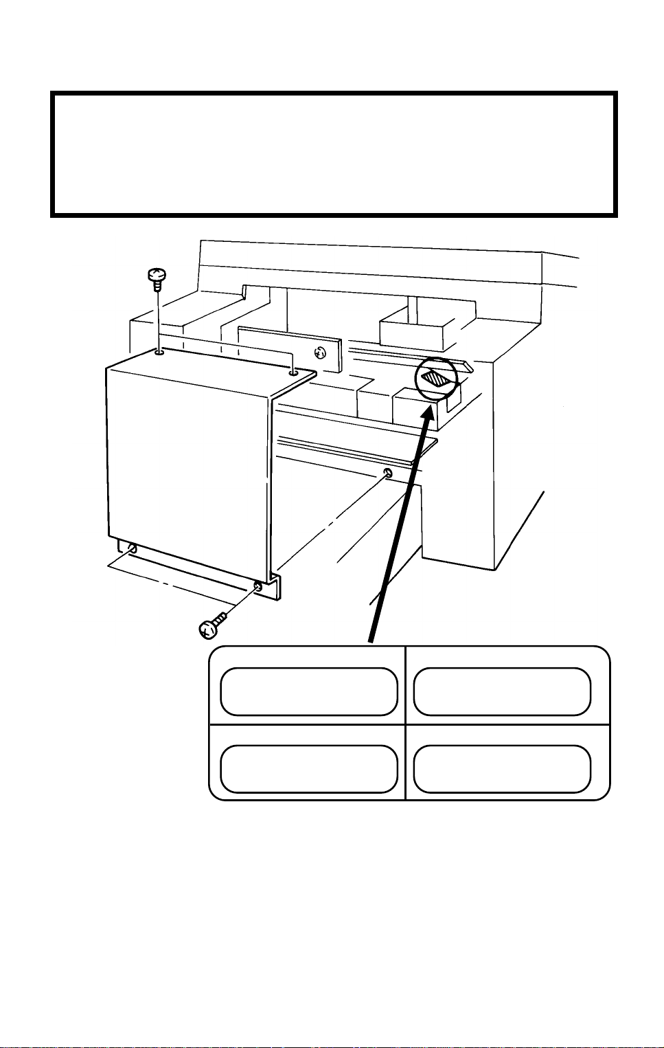
INSTALLATION November 30th, 1991
CONNECTING UP THE MACHINE
3. INSTALLATION
3.1. CONNECTING UP THE MACHINE
POWER
SWITCH
220-240V
50Hz
Grounded
LINE
TEL
3
Phone
Company’s
Jack
HANDSET
3-1
Page 56

Installation Procedure
1. Install the master unit. (refer to the Installation Manual)
2. Install the toner cartrige. (refer to the Installation pro cedure on the carton box)
3. Install the handset and connect the line. (refer to next page)
4. Install the paper cassette. ( r efer to the Operator’s Manual)
5. Attach the trays and document table.
Page 57

[B]
[A]: 1 screw
November 30th, 1991 INSTALLATION
INSTALLING OPTIONAL UNITS
3.2. INSTALLING OPTIONAL UNITS
3.2.1. Lower Cassette
Check whether there are any messages in the memory. If there are, you
must install the lower cassette and turn the power back on within an hour.
[A]
[B]
[D]
[C]
[C]
Fit pegs [B] into holes [C].
[D]: 5 screws
3-2
Page 58

[F]
[G]
[H]
INSTALLATION November 30th, 1991
INSTALLING OPTIONAL UNITS
[F]
[E]
[E]: 2 connectors
3
Remove two screws [F].
[G]
Install brackets [G] (2 screws each).
Screws [H]: Use previously removed
screws [F].
Screws [I]: In the accessories bag.
[I]
3-3
Page 59

November 30th, 1991 INSTALLATION
INSTALLING OPTIONAL UNITS
[J]
Adjust the cassette in accordance
with customer requirements.
3-4
Page 60

INSTALLATION November 30th, 1991
INSTALLING OPTIONAL UNITS
3.2.2. Memory Card
• Turn off the power before installing or removing a memory card.
• Make sure that 100% is displaye d on the operat ion panel before install-
ing or removing a memory card, or data may be lost.
3
3-5
Page 61

November 30th, 1991 INSTALLATION
INSTALLING OPTIONAL UNITS
3.2.3. Cassette (250 Sheets)
3-6
Page 62

INSTALLATION November 30th, 1991
INSTALLING OPTIONAL UNITS
3.2.4. Cassette (500 Sheets)
3
3-7
Page 63

November 30th, 1991 INSTALLATION
INSTALLING OPTIONAL UNITS
3.2.5. Handset
[A]
[A]: 2 screws
[B]
3-8
Page 64

INSTALLATION November 30th, 1991
INSTALLING OPTIONAL UNITS
3.2.6. Language ROM Selection
The standard ROM contains the following languages: English, German, Italian, Swedish, Spanish. The user can select one of the se la ng ua ge s with a
user programming function.
If the user wishes to use French, install the French language ROM. This
ROM contains the following lang ua ges: En glish , German, Italian, Swedish,
French. In the same way as for the standa rd ROM, the user can select one of
these languages with a user progra mming function.
Note: • Switch the machine off before chan gin g the ROM.
• Make sure that there are no messa ges in the memory be fo re you
change the ROM, or data will be lost.
3
3-9
Page 65

November 30th, 1991 INSTALLATION
INITIAL PROGRAMMING
3.3. INITIAL PROGRAMMING
Check the following:
• Are the country codes for NCU parameters (Fun ctio n 96, parameter 00)
and bit switch settings (bit switch 0F) correct fo r the coun try of insta llation?
• Are the NCU jumper setting s correct for the country of installa tio n (see
section 2-3-7)?
• Do any bit switch or other setting s have to be changed to match line
conditions or user requirements?
• Have the correct operatio n panel decals and Quick Dial sheets been in-
stalled from the language kit?
• Have you programmed th e serial number (Function 98, sect ion 4-1-18)?
In some countries, the use r ca nn ot prog ram the following items, so program
them before you lea ve th e machine.
• Telephone Line Type (Function 71, section 4-1-23)
• CSI (Function 53, section 4-1-22)
The user should program the follo wing items after installation:
• Telephone Line Type (in some countries, this is not a user adjust ment)
• RTI, TTI, and CSI (in some coun trie s, CSI is not a user adjustment)
• ID Codes (ID Code, Remote ID, Confidential ID, Memory Lock ID)
• The fax machine’s own telephone number
• Date and T ime
• Language Selection
3-10
Page 66

SERVICE TABLES AND PROCEDURES November 30th, 1991
SERVICE LEVEL FUNCTIONS
4. SERVICE TABLES AND PROCEDURES
4.1. SERV ICE LEVEL FUNCTIONS
4.1.1. Bit Switch Programming (Function 91)
1. Function 5 1 9 9 1
then immediately Yes
2. 9 1 Yes
Bit 7 is displayed at the lef t, and bit 0 at
the right.
3. Increment bit switch: #
Decrement bit switch:
Example: Display bit switch 3: # x 3
4. Adjust the bit swit ch.
Example: To change the value of bit
7, press 7
5. Either:
• Adjust more bit switches - go to step 3.
*
FUNCTION Y/∇
9 SERVICE FUNCTIONS
DEFAULT: 0000 0000
BITSW 00: 0000 0000
DEFAULT: 0000 0000
BITSW03: 0000 0000
DEFAULT: 0000 0000
BITSW03: 1000 0000
4
• Finish - Function
4-1
Page 67

November 30th, 1991 SERVICE TABLES AND PROCEDURES
SERVICE LEVEL FUNCTIONS
4.1.2. System Parameter List (Function 92)
1. Function 5 1 9 9 1
then immediately Yes
2. 9 2 Yes Start
After printing, press Function
4.1.3. Error Code Display (Function 93)
1. Function 5 1 9 9 1
then immediately Yes
2. 9 3 Yes
3. Either:
Scroll through the error code s - #
Finish - Function
4.1.4. Service Monitor (Function 93)
FUNCTION Y/∇
9 SERVICE FUNCTIONS
FUNCTION Y/∇
9 SERVICE FUNCTIONS
ERROR CODE #/∇
1-01 JAN 01 17:30
1. Function 5 1 9 9 1
then immediately Yes
2. 9 3 Yes
3.
No/∇ Start
FUNCTION Y/∇
9 SERVICE FUNCTIONS
ERROR CODE #/∇
1-01 JAN 01 17:30
4.1.5. Protocol Dump (Function 94)
1. Function 5 1 9 9 1
then immediately Yes
FUNCTION Y/∇
9 SERVICE FUNCTIONS
2. 9 4 Yes START
PROTOCOL DUMP LIST
3. Start
4-2
Page 68

SERVICE TABLES AND PROCEDURES November 30th, 1991
SERVICE LEVEL FUNCTIONS
4.1.6. RAM Display/Rewrite (Function 95)
1. Function 5 1 9 9 1
then immediately Yes
2. 9 5 Yes
FUNCTION Y/∇
9 SERVICE FUNCTIONS
Y/∇
DISPLAY MEMORY
3. Yes ADDRESS = 2044C
DATA = 03
4. Input the address that you wish to see. Example: Address 20202
2 0 2 0 2
ADDRESS = 20202
DATA = 00
Note: The first digit must always be 2.
5. If you wish to change the data, type in the new data.
Example: 80, press 8 0 ADDRESS = 20202
DATA = 80
Note: If you wish to move the curso r, press
→
6. Either:
• View more addresses - g o to st ep 4.
• Finish - Yes Function
4.1.7. RAM Dump (Function 95)
1. Function 5 1 9 9 1
then immediately Yes
2. 9 5 Yes
3.
∇ Yes
4. Input the bank number (B) and the start and
end addresses. Max. range : 25 6 byt es
Example: Start at 1200, end at 12FF.
1 2 0 0 1 2 F F Start MEMORY DUMP START
4
FUNCTION Y/∇
9 SERVICE FUNCTIONS
Y/∇
DISPLAY MEMORY
MEMORY DUMP START/N
B=2, ST-0000,END-00FF
The value of B is always 2.
B=2, ST-1200,END-12FF
4-3
Page 69

November 30th, 1991 SERVICE TABLES AND PROCEDURES
SERVICE LEVEL FUNCTIONS
4.1.8. NCU Parameters (Function 96)
1. Function 5 1 9 9 1
then immediately Yes
FUNCTION Y/∇
9 SERVICE FUNCTIONS
2. 9 6 Yes NCU PARAMETER KPAD/Y
NO.00 001
3. Scroll through the parameters - Yes
Enter new values at the keypad.
Example: Set NCU parameter 04 to 005 .
Yes Yes Yes Yes 0 0 5 NCU PARAMETER KPAD/Y
NO.04 005
4. To finish: Function
Note: Parameter 00 is the Country Code, and Parameter 01 is the Tx Level
(if the Tx level should be -9 dB, input 9 ).
Refer to section 4-3 for full details on NCU parameters.
4.1.9. ADF Test (Function 97)
1. Function 5 1 9 9 1
then immediately Yes
2. 9 7 Yes
FUNCTION Y/∇
9 SERVICE FUNCTIONS
SCN-1 DT-2 PL-3 LD-4
MDM-5 RI-6 CK-7 SN-8
3. 1 SCANNER TEST KPAD
ADF-1 LAMP-2
4. 1
5. Function Function
6. Place a document in the feeder,
then press Copy Start
4-4
Page 70

SERVICE TABLES AND PROCEDURES November 30th, 1991
SERVICE LEVEL FUNCTIONS
4.1.10. Xenon Lamp Test (Function 97)
1. Function 5 1 9 9 1
then immediately Yes
FUNCTION Y/∇
9 SERVICE FUNCTIONS
2. 9 7 Yes SCN-1 DT-2 PL-3 LD-4
MDM-5 RI-6 CK-7 SN-8
3. 1
SCANNER TEST KPAD
ADF-1 LAMP-2
4. 2 SCANNER LAMP TEST
The xenon lamp lights up for 5 minutes.
4.1.11. DTMF T one Test (Function 97)
1. Function 5 1 9 9 1
then immediately Yes
FUNCTION Y/∇
9 SERVICE FUNCTIONS
2. 9 7 Yes SCN-1 DT-2 PL-3 LD-4
MDM-5 RI-6 CK-7 SN-8
3. 2
DTMF TEST
DUAL-1 SINGLE-2
4. Either:
• Test dual tones - 1 . Go to step 5.
• Test single tones - 2 . Go to step 8.
5. The display is as shown opposite. DUAL TONE
PRESS KEYPAD
Press a key on the ten key pad.
Example: 1 Start
6. To stop the test: Stop
7. Either:
Test another tone: Go to step 5.
Finish: Function
4
4-5
Page 71

November 30th, 1991 SERVICE TABLES AND PROCEDURES
SERVICE LEVEL FUNCTIONS
8. The display is as shown opposite.
Press the required key.
697 Hz 1 852 Hz 3 1209 Hz 5 1477 Hz 7
770 Hz 2 941 Hz 4 1336 Hz 6 1633 Hz 8
Example: To test 1633 Hz, press 8 Start
9. To stop the test: Stop
10. Either:
Test another tone: Go to step 8.
Finish: Function
4.1.12. Printer Test Patterns (Function 97)
1. Function 5 1 9 9 1
SINGLE TONE
PRESS KEYPAD
then immediately Yes
FUNCTION Y/∇
9 SERVICE FUNCTIONS
2. 9 7 Yes SCN-1 DT-2 PL-3 LD-4
MDM-5 RI-6 CK-7 SN-8
3. 3
PATTERN PRINT KPAD
1-7
4. Press a key from 1 to 7, excluding 5 and 6. (Patterns 5 and 6 are not
used in this model. ) A test pattern is printed.
4.1.13. Operation Panel Test (Function 97)
1. Function 5 1 9 9 1
then immediately Yes
FUNCTION Y/∇
9 SERVICE FUNCTIONS
2. 9 7 Yes SCN-1 DT-2 PL-3 LD-4
MDM-5 RI-6 CK-7 SN-8
3. 4
4-6
Page 72

SERVICE TABLES AND PROCEDURES November 30th, 1991
SERVICE LEVEL FUNCTIONS
4.1.14. Modem Test (Function 97)
1. Function 5 1 9 9 1
then immediately Yes
FUNCTION Y/∇
9 SERVICE FUNCTIONS
2. 9 7 Yes SCN-1 DT-2 PL-3 LD-4
MDM-5 RI-6 CK-7 SN-8
3. 5
MODEM TEST
G3-1 TONE-2
4. Either:
Test G3 carrier signals - 1 . Go to step 5.
Test frequencies - 2 . Go to step 8.
5. The display is as shown opposite. 9600-1 7200-2
4800-3 2400-4 300-5
Press the required key.
Example: Test the 9600 bps carrier 1 Start
6. To stop the test: Stop
7. Either:
Test another tone: Go to step 5.
Finish: Function
8. The display is as shown opposite. 2100-1 1100-2 800-3
PRESS KEYPAD
Press the required key.
Example: To test 1100 Hz, press 2 Start
9. To stop the test: Stop
10. Either:
• Test another tone: Go to step 8.
• Finish: Function
4
4-7
Page 73

November 30th, 1991 SERVICE TABLES AND PROCEDURES
SERVICE LEVEL FUNCTIONS
4.1.15. Ringer Test (Function 97)
Not used; do not try to use this functio n.
4.1.16. Buzzer Test (Function 97)
1. Function 5 1 9 9 1
then immediately Yes
2. 9 7 Yes
3. 7
Press the Stop key to stop the buzzer.
4.1.17. Ozone Fan Test (Function 97)
1. Function 5 1 9 9 1
then immediately Yes
2. 9 7 Yes
3. 8
Press the Function key to stop the fan .
FUNCTION Y/∇
9 SERVICE FUNCTIONS
SCN-1 DT-2 PL-3 LD-4
MDM-5 RI-6 CK-7 SN-8
FUNCTION Y/∇
9 SERVICE FUNCTIONS
SCN-1 DT-2 PL-3 LD-4
MDM-5 RI-6 CK-7 SN-8
4.1.18. Serial Number (Function 98)
1. Function 5 1 9 9 1
then immediately Yes
2. 9 8 Yes
3. Enter the machine’s serial no at the keyp ad .
To correct a mistake: No
4. If the display is correct: Yes
4-8
FUNCTION Y/∇
9 SERVICE FUNCTIONS
SERIAL # KPAD
SERIAL # KPAD/Y/N
7940479186
Page 74

SERVICE TABLES AND PROCEDURES November 30th, 1991
SERVICE LEVEL FUNCTIONS
4.1.19. Service Station Telephone Number (Function 99)
1. Function 5 1 9 9 1
then immediately Yes
2. 9 9 Yes TEL NUMBER KEYPAD
3. Input the telephone numbe r of the service station that will receive Auto
Service calls from this machine.
4. Yes Function
4.1.20. Bypassing Restr icted Acces s
Use this procedure if the use r has switched on Restricted Access. Th is e nables you to use the mach ine wit hout having to input a Person al Code. It is
also useful if the user canno t op era te the machine because th ey can no t remember any of the Personal Codes.
1. 2 2 2 2
FUNCTION Y/∇
9 SERVICE FUNCTIONS
TEL NUMBER KPAD/Y/N
2125555242
2. Immediately press Quick Dial key 11
Then operate the mach ine as you wish. When the machine is returned to
standby mode, Restricted Acce ss is reimpose d immediat ely.
4.1.21. Printing all Memory Files (Function 24)
First, set bit 5 of bit switch 01 to 1.
1. Function 2 4 Yes FILE NO
2. Press
All files in the memory, including confident ial messa ge s, will be prin ted one
by one. The files will not be erased.
After you have finished, set bit 5 of bit switch 01 back to 0.
Note: To erase memory files, set bit 2 o f bit switch 00 to 1. All files will be
No/∇ Yes Start .
erased, and some RAM addresse s will also be cleared.
4
4-9
Page 75

November 30th, 1991 SERVICE TABLES AND PROCEDURES
SERVICE LEVEL FUNCTIONS
4.1.22. CSI Programming
This procedure is for use in countrie s where CSI programming is a service
function.
First, set bit 5 of bit switch 01 to 1.
1. Function 5 2 2 2 2
5 3 Yes
2. Press No twice.
Y/∇
SET RTI
Y/∇
SET CSI
3. Press Yes . CSI KPAD
4. Input the CSI.
CSI KPAD/Y/N
Note: Not more than 20 digits.
2015559456
5. Press Yes Function .
After you have finished, set bit 5 of bit switch 01 back to 0.
4.1.23. Telephone Line Type Selection
This procedure is for use in countries where telephone line type selection is a
service function.
First, set bit 5 of bit switch 01 to 1.
1. Function 5 2 2 2 2
7 1 Yes
2. Press Yes .
Y/∇
SELECT TT/DP
LINE = TT Y
TT=1 DP=2
3. Either:
Select tone dialling - 1 .
Select pulse dialling - 2 .
Finish: Function
After you have finished, set bit 5 of bit switch 01 back to 0.
4-10
Page 76

SERVICE TABLES AND PROCEDURES November 30th, 1991
BIT SWITCHES
4.2. BIT SWITCHES
WARNING
Do not adjust a bit switch that is described as "Not used", as this
may cause the machine to malfunction or to operate in a manner
that is not accepted by local regulations. Such bits are for use only
in other areas, such as Japan.
Bit Switch 00
FUNCTION COMMENTS
0 MTF process
0: Enabled 1: Disabled
1 RAM reset level 2
1: Reset
2 RAM reset level 3
1: Reset
Note: RAM reset level
1 is a RAM
adjustment. It is not
described in this
manual.
3 Memory file forwarding
1: Forward the files
4 Inclusion of technical
data on the Journal
0: No 1: Yes
5 Monitor speaker
during video data
communication (tx
and rx)
0: Disabled
1: Enabled
6 Not used Do not change the factory setting.
Continued on the next page
0: The MTF process is used when required by the software.
1: The MTF process is never used.
When this bit is set to 1, all items stored in the RAM are
reset except the clock, and then this bit changes back to 0
automatically. Also, all image files in the SAF memory are
erased.
When this bit is set to 1, some items stored in the RAM are
reset, then this bit changes back to 0. All items are reset
except the bit switch and NCU parameter settings, clock,
own tel. no., CSI, RTI, TTI, Quick Dials, Speed Dials,
Groups, and the Journal memory. Also, all image files in the
SAF memory are erased.
This bit switch is recommended for use when it is necessary
to clear the SAF, as fewer RAMs will need reprogramming.
Use this if the printer does not work, but the user wishes to
print the files. First, change the fax machine’s telephone
number (Function 51) to the number to which you wish to
forward the files, then set this bit to 1. All files in the memory
will be forwarded. This bit resets to 0 automatically.
However, you must return the fax machine’s telephone
number to the original setting. The files stay in memory.
1: Instead of the personal code, the following data are listed
on the Journal as a six-figure number.
First two numbers: Final modem rate (for example, 96
means 9,600 bps)
Second two numbers (Rx mode only): Rx signal level (Level
= 0 - 0.375x, where x is the value on the report; accurate to
3 dB)
Third two numbers (Rx mode only): Rx cable equalizer; 00 =
Equalizer is Off, 01 = Equalizer is On
Used for testing. Set this bit to 1 to hear the fax data signal
(phase C of CCITT T.30 protocol).
Make sure that you reset this bit after testing.
4
4-11
Page 77

November 30th, 1991 SERVICE TABLES AND PROCEDURES
BIT SWITCHES
Bit Switch 00
FUNCTION COMMENTS
7 Communication
parameter display
0: Disabled
1: Enabled
Communication parameter display
This is a fault-finding aid. The LCD shows the key
parameters (see below). This is normally disabled because
it cancels the CSI display for the user.
Make sure that you reset this bit after testing.
Modem rate
(bps)
96: 9600
72: 7200
48: 4800
24: 2400
Bit Switch 01
0
LCD contrast
Bit 2 1 0 Contrast
1
0 0 0 Brightest
0 0 1 ↓
2
↓ ↓
1 1 0 ↓
1 1 1 Darkest
Memory read/write by RDS
Bit 4 3 Setting
3
0 0 Always enabled
0 1 User selectable
4
1 0 User selectable
1 1 Always disabled
5 Dedicated transmission parameter
programming/printing all SAF files
0: Disabled 1: Enabled
6 Not used Do not change the factory setting.
Continued on the next page
Sub-scan
Resolution
S: 3.85
l/mm
D: 7.7 l/mm
F: 15.4 l/mm 1E: MH+EFC
FUNCTION COMMENTS
Coding Width and
reduction
1D: MH
2D: MR
2E: MR+EFC
1C: MH+ECM
2C: MR+ECM
MC: MMR+ECM
A: A4 [8.3"]
B: B4 [10.1’]
C: A3 [1 1.7"]
N: No reduction
R: Reduction
Use these bit switches to adjust the brightness
of the LCD on the operation panel.
(0,0): At any time, an RDS system can read or
write RAM data such as TTI and bit switches.
(0,1), (1,0): Normally, RDS systems are locked
out, but the user can temporarily switch RDS
on to allow an RDS operation to take place.
RDS will automatically switch off again after a
certain time, which is stored in a RAM address
(see section 4-5). Note that, if an RDS
operation takes place, RDS will not switch off
until this time limit has expired.
(1,1): All RDS systems are always locked out.
This bit must be set to 1 before attempting to
program dedicated transmission parameters or
printing all files stored in the SAF memory. If
CSI and /or telephone line type is a service
mode in your area, this bit must also be at 1
before programming.
DCS:
CCITT G3
NSS:
Nonstandard G3
Mode I/O Rate
(ms/line)
0M: 0
5M: 5
10M: 10
20M: 20
40M: 40
4-12
Page 78

SERVICE TABLES AND PROCEDURES November 30th, 1991
BIT SWITCHES
Bit Switch 01
FUNCTION COMMENTS
7 Auto Service Call for PM
0: Enabled 1: Disabled
Bit Switch 02
FUNCTION COMMENTS
0 Page separation mark
0: Enabled 1: Disabled
1 Repetition of data when the
received page is longer than the
printer paper
0: Disabled 1: Enabled
2 Reduction of the length of
received data
0: Enabled 1: Disabled
3 Not used Do not change the factory settings.
4
5
Maximum transmittable document
length
6
Bit 7 6 Setting
0 0 600 mm
7
0 1 1200 mm
1 0 14 m
1 1 100 m
0: The machine will send an Auto Service Call
when the PM interval has expired. This interval
is adjustable by RAM address. The default
setting is every 30,000 copies (based on the
Print counter).
1: The user will do maintenance as explained
in the Operator’s Manual whenever problems
occur.
0: If a received page has to be printed out on two
sheets, an "x" inside a small box is printed at the
bottom right hand corner of the first sheet, and a
"2" inside a small box is printed at the top right
hand corner of the second sheet. This helps the
user to identify pages that have been split up.
1: No marks are printed.
0: The next page continues from where the
previous page left off
1: The final few mm of the previous page are
printed at the top of the next page.
See section 2-2-1, subsection 5, for details.
This bit determines whether incoming pages are
reduced to fit on the copy paper if they are
almost the same length as the copy paper in the
cassette. See section 2-2-1, subsection 5, for
details.
If the user wants to send very long documents
such as well logs, use the 14 m or 100 m setting.
4
4-13
Page 79

November 30th, 1991 SERVICE TABLES AND PROCEDURES
BIT SWITCHES
Bit Switch 03
FUNCTION COMMENTS
0 Dialling with the handset off-hook
0: Enabled
1: Disabled
1 Lifetime of polling standby files in
the memory
0: Erased after being polled
1: Kept until user erases
2 Inclusion of communications on
the Journal when no image data
was exchanged.
0: No 1: Yes
3 Printing of the error code on the
error report
0: No 1: Yes
4 Not used Do not change the factory setting.
5 Printing the TTI in copy mode
0: No 1: Yes
6 Printing the received RTI/CSI
0: No 1: Yes
7 Reconstruction time for the first
line in receive mode
0: 6 s 1: 10 s
If this bit is 1, the user will not be able to dial if
the handset is off hook.
0: Messages stored for polling transmission will
be erased immediately after polling.
1: This setting allows the user to keep messages
in the memory to be polled by more than one
station.
If communication did not reach phase 3 of
CCITT T.30 protocol (such as for a telephone
call), this communication can be listed on the
Journal if this bit is at 1.
If this bit is 1, error codes are printed on the error
reports for the user.
If this bit is 1, the TTI stored in the machine is
printed at the top of the copy.
In addition to the TTI, the other end’s RTI or CSI
will be printed on top of the pages that the
machine receives.
When the sending terminal is controlled by a
computer, there may be a delay in receiving
page data after the local machine accepts set-up
data and sends CFR. If this occurs, set this bit to
1 to give the sending machine more time to send
data.
4-14
Page 80

SERVICE TABLES AND PROCEDURES November 30th, 1991
BIT SWITCHES
Bit Switch 04
FUNCTION COMMENTS
Compression modes available in
receive mode
0
Bit 1 0 Modes
0 0 MH only
1
0 1 MR or MH
1 0 MR or MH, with
EFC
1 1 MMR, MR, or
MH, with EFC
2 Error counting method
0: 10 (20) [40]
1: In accordance with the settings
of bits 3 to 7
Burst error threshold
3
Bit 4 3 Threshold
0 0 3 (6) [12]
4
0 1 4 (8) [16]
1 0 5 (10) [20]
1 1 6 (12) [24]
Error line ratio
5
Bit 7 6 5 Value
0 0 0 5%
6
0 0 1 6%
0 1 0 7%
7
0 1 1 8%
1 0 0 9%
1 0 1 10%
These bits determine what capabilities are
informed to the transmitting side in the protocol
exchange.
The machine counts data errors caused by a
noisy line or defective machine.
0: If the count reaches 10 (Standard mode), 20
(Detail mode), or 40 (Fine mode), the machine
sends RTN to the other end in reply to the postmessage command. As 10 (or 20 or 40) good
lines cause the count to decrement, RTN will
only occur in bad conditions.
If there are more consecutive error lines in the
received page than the threshold specified by
these bits, the page is rejected. Values in
parenthesis are for Detail resolution, and those
in square brackets are for Fine resolution.
If the number of error lines divided by the total
number of lines reaches the value determined
by the settings of these bits, RTN will be sent to
the other end.
4
4-15
Page 81

November 30th, 1991 SERVICE TABLES AND PROCEDURES
BIT SWITCHES
Bit Switch 05
FUNCTION COMMENTS
Compression modes available in
transmit mode
0
Bit 1 0 Modes
0 0 MH only
1
0 1 MR or MH
1 0 MR or MH, with
EFC
1 1 MMR, MR, or
MH, with EFC
2 PABX dial tone detection
0: Enabled
1: Disabled
3 PSTN dial tone detection
0: Enabled
1: Disabled
4 Busy tone detection
0: Enabled
1: Disabled
5 Not used Do not change the factory setting.
PSTN access method through
6
PABX
Bit 7 6 Method
7
0 0 No PABX
0 1 Loop Start
1 0 Ground Start
1 1 Flash Start
These bits determine what capabilities are
informed to the receiving side in the protocol
exchange.
0: PABX dial tone is detected in accordance
with the parameters programmed in RAM. The
machine will wait for the dial tone before trying
to gain access to the PSTN.
0: PSTN dial tone is detected in accordance
with the parameters programmed in RAM. The
machine will wait for the dial tone before dialling
out.
0: Busy tone is detected in accordance with the
parameters programmed in RAM. The machine
will not have to wait out the CCITT T1 time
before hanging up if the line is busy.
Set these bits to match the type of signal
accepted by the PABX. If there is no PABX
between the machine and the network, set both
bits to 0.
Bit Switch 06
FUNCTION COMMENTS
0
PSTN access number
1
Access No. Hex value of bit switch
0 F0
2
↓ ↓
9 F9
3
00 00
4
↓ ↓
99 99
5
6
7
Program this bit switch if the machine is
behind a PABX. The access number is
the number the user must dial to get an
outside line. If the machine detects the
access number at the start of a
telephone number, it will connect with
the PABX, pause for a few seconds,
then dial the number.
Example: If the access number for the
PABX is 9, the bit switch must be F9. To
do this, set all bits to 1 except bits 1 and
2.
If there is no PABX, set all bits to 1.
4-16
Page 82

SERVICE TABLES AND PROCEDURES November 30th, 1991
BIT SWITCHES
Bit Switch 07
FUNCTION COMMENTS
0 Back to back test
0: Disabled
1: Enabled
1 Short preamble
0: Enabled 1: Disabled
2 Not used Do not change the factory setting.
3 Echo countermeasure
0: Enabled
1: Disabled
4 DIS detection number
0: 1
1: 2
5 ECM
0: On 1: Off
6 Post-message response timing (rx)
0: After feed-out
1: When the leading edge reaches the
copy feed-out sensor
7 FTZ protocol
0: Disabled 1: Enabled
Set this bit to 1 when you wish to do a back
to back test.
If this bit is 0, the Short Preamble feature is
switched on.
If the setting is 1, the machine will hang up if
it receives the same signal twice. If the
setting is 0, the machine will ignore echoes
from the line.
The machine will send DCS (G3 set-up
signal) if it receives DIS. If echoes are
frequent, setting this bit to 1 will allow the
machine to wait for the second DIS before
sending DCS.
If this bit is 0, ECM is switched on.
0: Data cannot be stored in the SAF during
reception if the memory is full, so, if this bit is
0, the machine will wait until the page has
been fed out. However, communication will
take longer to complete.
1: The post message response is sent
earlier, but the paper has not been fed out
yet, so if there is a jam after this, data may
be lost.
This bit is ignored during memory reception.
This bit must be set to 1 in Germany.
4
Bit Switch 08 (Transmission)
FUNCTION COMMENTS
0
Initial Tx modem rate
Bit 2 Bit 1 Bit 0 Setting
1
0 1 1 9,600 bps
0 1 0 7,200 bps
2
0 0 1 4,800 bps
0 0 0 2,400 bps
Other settings: Not used
3 Not used Do not change the factory settings.
4
5
6
7
These bits set the initial starting modem
rate for transmission. This rate may fall
back to a slower rate depending on line
conditions and the remote terminal’s
capabilities.
4-17
Page 83

November 30th, 1991 SERVICE TABLES AND PROCEDURES
BIT SWITCHES
Bit Switch 09 (Transmission)
FUNCTION COMMENTS
0 CNG signal transmission in
manual transmission mode
0: Disabled
1: Enabled
12Wrong connection prevention
method
Bit 2 Bit 1 Setting
0 0 None
0 1 8 digit CSI
1 0 4 digit CSI
1 1 CSI/RTI
3 Closed network (transmission)
0: Disabled
1: Enabled
4 Monitor speaker status during
memory transmission
0: Off 1: On
5 Not used Do not change the factory settings.
6
7
CNG (calling tone) is normally used by auto-dial fax
machines to alert a manual machine operator that
an auto-transmitting machine is on the line waiting
to transmit. This tone is not needed for manual
operation (full number dialling).
(0,1) - The machine will not transmit if the last 8
digits of the received CSI do not match the last 8
digits of the dialled telephone number. This does not
work for manual dialling.
(1,0) - The same as above, except that only the last
4 digits are compared.
(1,1) - The machine will not transmit if the other end
does not identify itself with an RTI or CSI.
(0,0) - Nothing is checked; transmission will always
go ahead.
1: Transmission will not go ahead if the ID code of
the other terminal does not match the ID code of
this terminal. This feature may not be reliable when
communicating with another maker’s product.
If this bit is 1, the speaker will operate during
memory transmission. Keep this bit at 0 if the user
complains about the noise from the speaker.
4-18
Page 84

SERVICE TABLES AND PROCEDURES November 30th, 1991
BIT SWITCHES
Bit Switch 0A (Reception)
FUNCTION COMMENTS
0
Initial Rx modem rate
Bit 2 Bit 1 Bit 0 Setting
1
0 1 1 9,600 bps
0 1 0 7,200 bps
2
0 0 1 4,800 bps
0 0 0 2,400 bps
Other settings: Not used
3 Not used Do not change the factory settings.
4
5
6 Cable equalizer (rx mode)
0: Off 1: On
7 Not used Do not change the factory setting.
The setting of these bits is used to inform
the sending machine of the initial starting
modem rate for the machine in receive
mode. If 9,600 bps presents a problem
during reception, use a lower setting.
Set this bit to 1 if there is signal loss at
higher frequencies because of the length
of wire between the modem and the
telephone exchange.
Also, try using the cable equalizer if one or
more of the following symptoms occurs.
•Communication error with error codes
such as 0-20, 0-23, etc.
•Modem rate fallback occurs frequently.
4
4-19
Page 85

November 30th, 1991 SERVICE TABLES AND PROCEDURES
BIT SWITCHES
Bit Switch 0B (Reception)
FUNCTION COMMENTS
0 Closed network (reception)
0: Disabled
1: Enabled
1 Training error tolerance
0: Type 1
1: Type 2
23Training error tolerance
Bit 3 2 Type 1 Type 2
0 0 15 14
0 1 10 9
1 0 2 4
1 1 0 1
4 Not used Do not change the factory settings.
5
6
7
1: Reception will not go ahead if the ID code
of the other terminal does not match the ID
code of this terminal. This feature may not be
reliable when communicating with another
maker’s product.
This bit determines the values available with
bits 2 and 3.
Type 1 can be used anywhere. Type 2 is
normally used only in Europe.
If the machine detects more errors during
training than the number set by these bits,
training fails and the machine will send FTT.
The data will be resent at a lower rate.
Bit Switch 0C
FUNCTION COMMENTS
0 European protocol requirements
0: Disabled 1: Enabled
1 German dialling requirements
0: Disabled 1: Enabled
2 Austrian dialling requirements
0: Disabled 1: Enabled
3 Norwegian dialling and protocol
requirements
0: Disabled 1: Enabled
4 Danish dialling requirements
0: Disabled 1: Enabled
5 French requirements
0: Disabled 1: Enabled
6 Swiss requirements
0: Disabled 1: Enabled
7 Not used Do not change the factory setting.
Adjust these bits in accordance with the
country of installation.
4-20
Page 86

SERVICE TABLES AND PROCEDURES November 30th, 1991
BIT SWITCHES
Bit Switch 0D
FUNCTION COMMENTS
0 Not used Do not change the factory settings.
1
2
3
4
5
6 Contents of the top line of the LCD
when handset mode is in use
0: Telephone number dialled
1: HANDSET MODE
7 Not used Do not change the factory setting.
Bit Switch 0E
FUNCTION COMMENTS
0 Not used Do not change the factory settings.
1
2
3
4
5 Conditions for reception
0: Normal
1: RTI or CSI needed
6 Not used Do not change the factory settings.
7
0: The telephone number being dialled is
displayed.
1: Only HANDSET MODE is displayed.
1: If the sending machine does not transmit
an RTI or CSI, the call will be rejected, and
the machine will send DCN.
4
4-21
Page 87

November 30th, 1991 SERVICE TABLES AND PROCEDURES
BIT SWITCHES
Bit Switch 0F
FUNCTION COMMENTS
0
Country Code
to
7
00: France 10: Not used
01: Germany 11: USA
02: UK 12: Asia
03: Italy 13: Japan
04: Austria 14: Hong Kong
05: Belgium 15: South Africa
06: Denmark 16: Australia
07: Finland 17: New Zealand
08: Ireland 18: Singapore
09: Norway 19: Malaysia
0A: Sweden
0B: Switzerland
0C: Portugal
0D: Holland
0E: Spain
0F: Israel
This country code determines the factory
settings of a wide range of bit switches and
RAM addresses. However, it has no effect
on the NCU parameter settings and
communication parameter RAM addresses;
these are determined by the setting of NCU
parameter 00 (function 96).
Bit Switch 10
FUNCTION COMMENTS
0 Pulse dialling method
Bit 1 Bit 0 Setting
1
0 0 Normal (P=N)
0 1 Oslo (P=10 - N)
1 0 Sweden (N+1)
1 1 Sweden (N+1)
2 Not used Do not change the factory settings.
3
4
5
6
7
P=Number of pulses sent out, N=Number
dialled.
Do not change the factory settings.
Bit switches 11 to 1F are not used.
4-22
Page 88

SERVICE TABLES AND PROCEDURES November 30th, 1991
BIT SWITCHES
Factory Settings
The factory settings of all the bit swit che s are sho wn be low in he xad ecima l
code. The first digit represents bits 7 to 4, and the second digit represen ts
bits 3 to 0.
Universal version
Switch Setting Switch Setting Switch Setting Switch Setting
00 00 08 03 10 00 18 00
01 01 09 01 11 00 19 00
02 42 0A 03 12 28 1A 00
03 40 0B 02 13 00 1B 00
04 03 0C 01 14 00 1C 00
05 23 0D 00 15 00 1D 00
06 FF 0E 00 16 00 1E 01
07 06 0F 02 17 00 1F 85
Asia version
Switch Setting Switch Setting Switch Setting Switch Setting
00 00 08 03 10 00 18 00
01 01 09 01 11 00 19 00
02 42 0A 03 12 28 1A 00
03 08 0B 00 13 00 1B 00
04 03 0C 00 14 00 1C 00
05 23 0D 00 15 00 1D 00
06 FF 0E 00 16 00 1E 01
07 06 0F 12 17 00 1F 85
4
4-23
Page 89

November 30th, 1991 SERVICE TABLES AND PROCEDURES
BIT SWITCHES
The following tables show the chang es in th e factory settings for each country. The settings depend on the country code (bit swit ch 0F).
Note: Changes to the country code (bit switch 0F) are not included in the
following tables.
Table 1: Based on the Universal version
Country Code Differences (switch settings given in Hex code)
France 00 Switch 0C: 21
Germany
UK
Italy 03 None
Austria 04 Switch 0C: 05
Belgium 05 None
Denmark 06 Switch 0C: 11
Finland 07 None
Ireland 08 None
Norway 09 Switch 0C: 09
Sweden 0A Switch 10: 02
Switzerland 0B Switch 0C: 41
Portugal 0C None
Holland 0D None
Spain 0E None
01
02
Switch 02: 46, Switch 03: 41, Switch 05: 27, Switch 07:
86, Switch 0C: 03, switch 12: 28, Switch 1D: 08
None (the settings for the Universal version are based
on those required for the UK)
Table 2: Based on the Asia version (Cou ntry code 12)
Country Code Differences (switch settings given in Hex code)
Israel 0F None
Hong Kong 14
South Africa 15
Australia 16
New Zealand 17
Singapore 18
Malaysia 19
4-24
Page 90

SERVICE TABLES AND PROCEDURES November 30th, 1991
NCU PARAMETERS
4.3. NCU PARAME TERS
The following tables give the RAM addresses and units of calcula tio n of the
parameters that the ma chin e use s for ringing signal detection and automatic
dialling. The facto ry se tt ings for each country are also given. Most of these
must be changed by RAM read/write (Function 95), but some can be
changed using NCU Paramet er pro gra mming (Function 96); if Function 96
can be used, this will be indicated in the Remarks column. The RAM is programmed in hex code unless (BCD) is included in the Unit column.
When using RAM read/write, you must add the bank number before the fo urdigit RAM address number. See section 4-1-6 for details.
Address Function Unit Remarks
413B Country code [NCU parameters
only]
413C Line current detection time 20 ms Line current is not detected
413D Line current wait time
413E Line current drop detect time
413F PSTN dial tone upper frequency
limit (HIGH)
4140 PSTN dial tone upper frequency
limit (LOW)
4141 PSTN dial tone lower frequency
limit (HIGH)
4142 PSTN dial tone lower frequency
limit (LOW)
4143 PSTN dial tone detection time 20 ms If 4143 contains FF, the
4144 PSTN dial tone reset time 160 ms
4145 PSTN dial tone continuous tone
time
4146 PSTN dial tone permissible drop
time
4147 PSTN wait interval 160 ms
4148 Ringback tone detection time 20 ms Detection is disabled if this
4149 PSTN busy tone upper frequency
limit (HIGH)
414A PSTN busy tone upper frequency
limit (LOW)
414B PSTN busy tone lower frequency
limit (HIGH)
414C PSTN busy tone lower frequency
limit (LOW)
Hex Function 96 (parameter 00).
if 413C contains FF.
Hz (BCD) See Note 2.
machine pauses for the
20 ms
Hz (BCD) If 4149 is FF, detection is
pause time (4147).
contains FF.
disabled. See Note 2.
4
4-25
Page 91

November 30th, 1991 SERVICE TABLES AND PROCEDURES
NCU PARAMETERS
Address Function Unit Remarks
414D PABX dial tone upper frequency
limit (HIGH)
414E PABX dial tone upper frequency
limit (LOW)
414F PABX dial tone lower frequency
limit (HIGH)
4150 PABX dial tone lower frequency
limit (LOW)
4151 PABX dial tone detection time 20 ms If 4151 contains FF, the
4152 PABX dial tone reset time 160 ms
4153 PABX dial tone continuous tone
time
4154 PABX dial tone permissible drop
time
4155 PABX wait interval 160 ms
4156 PABX ring back tone detection
time
4157 PABX busy tone upper frequency
limit (HIGH)
4158 PABX busy tone upper frequency
limit (LOW)
4159 PABX busy tone lower frequency
limit (HIGH)
415A PABX busy tone lower frequency
limit (LOW)
415B Busy tone ON time: range 1 20 ms
415C Busy tone OFF time: range 1
415D Busy tone ON time: range 2
415E Busy tone OFF time: range 2
415F Busy tone ON time: range 3
4160 Busy tone OFF time: range 3
4161 Busy tone ON time: range 4
4162 Busy tone OFF time: range 4
4163 Busy tone continuous tone
detection time
4164 Busy tone signal state time tolerance for all ranges, and number of cycles
required for detection (a setting of 4 cycles means that ON-OFF-ON or OFF-
ON-OFF must be detected twice).
Hz (BCD) See Note 2.
machine pauses for the
20 ms
20 ms Detection is disabled if this
Hz (BCD) If this is FF, detection is
pause time (4155).
contains FF.
disabled. See Note 2.
See Note 2.
Tolerance (±)
Bit 1 0
0 0 75%
0 1 50%
1 0 25%
1 1 12.5%
Bits 7, 6, 5, 4 - number of cycles required for detection
4-26
Page 92

SERVICE TABLES AND PROCEDURES November 30th, 1991
NCU PARAMETERS
Address Function Unit Remarks
4165 International dial tone upper
frequency limit (HIGH)
4166 International dial tone upper
frequency limit (LOW)
4167 International dial tone lower
frequency limit (HIGH)
4168 International dial tone lower
frequency limit (LOW)
4169 International dial tone detection
time
416A International dial tone reset time 160 ms
416B International dial tone continuous
tone time
416C International dial tone permissible
drop time
416D International dial wait interval 160 ms
416E Country dial tone upper frequency
limit (HIGH)
416F Country dial tone upper frequency
limit (LOW)
4170 Country dial tone lower frequency
limit (HIGH)
4171 Country dial tone lower frequency
limit (LOW)
4172 Country dial tone detection time 20 ms If 4172 contains FF, the
4173 Country dial tone reset time 160 ms
4174 Country dial tone continuous tone
time
4175 Country dial tone permissible drop
time
4176 Country dial wait interval 160 ms
4177 Grounding time (ground start
mode)
4178 Break time (flash start mode) 1 ms The Di relay is open for this
4179 International dial access code BCD For a code of 100:
417A
417B PABX pause time 20 ms
417C Progress tone detection level, and
cadence detection enable flags
Hz (BCD) See Note 2.
20 ms If 4169 contains FF, the
machine pauses for the
pause time (416D).
20 ms
Hz (BCD) See Note 2.
machine pauses for the
pause time (4176).
20 ms
20 ms The Gs relay is closed for
this interval.
interval.
4179 - F1
417A - 00
Bit 7 Bit 6 dBm
1 1 -53
1 0 -32.5
0 1 -40.5
0 0 -29
4
Bits 3, 2, 1, 0 - See Note 3.
417D CCITT T1 time 2.56 s
4-27
Page 93

November 30th, 1991 SERVICE TABLES AND PROCEDURES
NCU PARAMETERS
Address Function Unit Remarks
417E Max. number of dials per station
(not using memory)
417F Redial interval (not using memory) 1 min
4180 Interval between dialling to
different stations
4181 Tx level from modem - dBm Function 96 (parameter 01).
4182 Acceptable ringing signal
frequency: range 1, upper limit
4183 Acceptable ringing signal
frequency: range 1, lower limit
4184 Acceptable ringing signal
frequency: range 2, upper limit
4185 Acceptable ringing signal
frequency: range 2, lower limit
4186 Number or rings until a call is
detected
4187 Minimum required length of the
first ring
4188 Minimum required length of the
second and subsequent rings
4189 Ringing signal detection reset time 40 ms Function 96 (parameter 09).
418A Time between opening or closing
the Ds relay and opening the Di
relay
418B Break time for pulse dialling See Note 5. Function 96
418C Make time for pulse dialling See Note 5. Function 96
418D Time between final Di relay
closure and Ds relay opening or
closing
418E Pause between dialled digits
(pulse dial mode)
418F Time waited when a pause is
entered at the operation panel
4190 DTMF tone on time 1 ms Function 96 (parameter 16).
4191 DTMF tone off time Function 96 (parameter 17).
4192 DTMF tone attenuation value - dBm Function 96 (parameter 18).
41B3 Max. time limit to dial a number 2.56 s All countries: 15[H] (53.76 s)
41B4 Max. no of consecutive pauses in
a telephone number
1
2.56 s
1000/
.672N
(Hz). N is
the value
stored
using
Function
96.
1 Function 96 (parameter 06).
20 ms See Note 6. Function 98
1 ms See Notes 5 and 8.
20 ms See Note 5. Function 96
Hex Germany: 1, Others: 250
Function 96 (parameter 02).
Function 96 (parameter 03).
Function 96 (parameter 04).
Function 96 (parameter 05).
(parameter 07).
Function 96 (parameter 08).
Function 96 (parameter 10).
(parameter 11).
(parameter 12).
See Notes 5 and 8.
Function 96 (parameter 13).
(parameter 14).
Function 96 (parameter 15).
See Note 7.
4-28
Page 94

SERVICE TABLES AND PROCEDURES November 30th, 1991
NCU PARAMETERS
Notes
1. If a setting is not required, store FF in the address.
2. Tone frequencies are stored in BCD in the following format.
Examples:
a) 380 Hz HIGH 0 3 LOW 8 0
b) 1210 Hz HIGH 1 2 LOW 1 0
3. Italy and Belgium only
RAM address 417C: the lower four bits have the following meanin g.
Bit 3 1: Country dial tone cadence detectio n enab led
Bit 2 1: International dial tone cadence detectio n en ab led
Bit 1 1: PABX dial tone cadence detection enabled
Bit 0 1: PSTN dial tone cadence detection enabled
If bit 3 is 1, the functions of the following RAM ad dre sses are chan ge d.
4172: tolerance for on or off state duration (%), coded as in 4164.
4174: on time, hex code (unit = 10 ms)
4175: off time, hex code (unit = 10 ms)
If bits 2, 1, or 0 are 1, the functions of the followin g ad dre sses are
changed in a similar way to that described for bit 3 = 1.
Bit 2 = 1: 4169, 416B, 416C
Bit 1 = 1: 4151, 4153, 4154
Bit 0 = 1: 4143, 4145, 4146
4. Belgium only
Address 4144 for DTMF dialling is 3.04 s. This can be adjusted by RAM
read/write. However, if pulse dial mode is selected, a value of 20 ms from
the ROM is used, and this cannot be adjusted.
5. Pulse dial parameters (addresses 418A to 418F) are the values for 10
pps. If 20 pps is used, the machine auto mat ically compensates.
6. The first ring may not be detected until 1 to 2.5 wavele ng ths after the time
specified by this parameter.
7. N must be between 0 and 15. The attenuation levels are as follows.
High frequency tone: - N dBm
Low frequency tone: - N - 3 dBm
8. 418A: Europe - Between Ds opening and Di opening, France - Betwee n
Ds closing and Di opening
418D: Europe - Between Ds closing and Di closing, France - Between Ds
opening and Di closing
4
4-29
Page 95

November 30th, 1991 SERVICE TABLES AND PROCEDURES
NCU PARAMETERS
On the following pages, there are tables of factory settings for each cou nt ry.
To enable the factory settings for a particu lar natio n, prog ram the Cou ntry
Code (RAM address 413B [use hex cod es] or use Function 96 [input the decimal value]) to the appropriate setting. The country code also affe cts the NCU
signal status (see section 2-3 -7).
• For each RAM address, there are two columns. The left han d co lumn
shows the actual value of the parameter. The right hand column shows
the value of the fact ory set ting that is stored in the RAM. The factory set tings are quoted either in hexade cimal cod e (th e act ua l cont ents of the
RAM address) if there is a H after the value in the table, or in decimal
(converted from the actua l h ex con tents of the RAM address) if the re is
no H after the value.
• Some RAMs must be stored using BCD; see the NCU Parameter defini-
tion table for details.
• If the table ent ry is blank, this means that the value is not used.
Country Code for NCU Parameters [or RAM Address 413B, in hex code]:
France: 00, Germany: 01, UK: 02, Italy: 03, Austria: 04, Belgium: 05, Denmark: 06, Finland:
07, Ireland: 08, Norway: 09, Sweden: 10 [0A], Switzerland: 11 [0B], Portugal: 12 [0C],
Holland: 13 [0D], Spain: 14 [0E], Israel: 15 [0F], USA: 17 [11], Asia: 18 [12], Japan: 19 [13],
Australia: 22 [16]
Tx Level (RAM Address 4181): All countries 6 (- 6dB), except the UK (10 [-10dB]), USA (9[9dB]), and Australia (12[-12dB]).
Country
France
Germany 1.1 s 55 4.1 s 205 1.06 s 53
413C 413D 413E 413F/4140
474 Hz
498 Hz
04(H) 74(H)
04(H) 98(H)
UK/Univ
Italy
Austria
Belgium
Denmark
Finland
Ireland 1.1 s 55 4.1 s 205 1.06 s 53
Norway
Sweden
Switz. 1.1 s 55 4.1 s 205
Portugal
Holland
Spain
Israel 1.1 s 55 4.1 s 205 1.06 s 53
471 Hz
512 Hz
471 Hz
512 Hz
536 Hz
450 Hz
512 Hz
512 Hz
608 Hz
450 Hz
563 Hz
480 Hz
498 Hz
04(H) 71(H)
05(H) 12(H)
04(H) 71(H)
05(H) 12(H)
05(H) 36(H)
04(H) 50(H)
05(H) 12(H)
05(H) 12(H)
06(H) 08(H)
04(H) 50(H)
05(H) 63(H)
04(H) 80(H)
04(H) 98(H)
USA
Asia
Australia
450 Hz
04(H) 50(H)
4-30
Page 96

SERVICE TABLES AND PROCEDURES November 30th, 1991
NCU PARAMETERS
Country 4141/4142 4143 4144 4145
France
Germany
406 Hz
370 Hz
04(H) 06(H) 2 s 100 12 s 75 1 s 50
03(H) 70(H) 2.1 s 105 20 s 125 2.1 s 105
UK
Italy
Austria
Belgium
Denmark
Finland
Ireland
Norway
Sweden
Switz.
Portugal
Holland
Spain
Israel
391 Hz
380 Hz
405 Hz
340 Hz
315 Hz
200 Hz
340 Hz
340 Hz
338 Hz
300 Hz
76 Hz
320 Hz
340 Hz
03(H) 91(H)
03(H) 80(H) 2.1 s 105 10.1 s 63 0.8 s 40
04(H) 05(H) 0.6 s 30 3.04 s 19 0.6 s 30
03(H) 40(H) 1.3 s 65 10.1 s 63 1.3 s 65
03(H) 15(H) 4.1 s 205 10.1 s 63 4.1 s 205
02(H) 00(H) 2.1 s 105 10.2 s 64 2.1 s 105
03(H) 40(H) 1.1 s 55 20 s 125 1.1 s 55
03(H) 40(H) 1.92 s 96 5.12 s 32 1.92 s 96
03(H) 38(H) 1.92 s 96 10.9 s 68 1.92 s 96
03(H) 00(H) 2.1 s 105 9.9 s 62 2.1 s 105
00(H) 76(H) 1.1 s 55 20 s 125 1.1 s 55
03(H) 20(H) 1.5 s 75 12.8 s 80 0.72 s 36
03(H) 40(H) 2.1 s 105 20 s 125 2.1 s 105
2, 50%
21(H) 10.9 s 68 0.6 s 60
USA
Asia
Australia
390 Hz
03(H) 90(H) 3.0 s 150 6 s 38 2 s 100
Country 4146 4147 4148 4149/414A
France 0.04 s 2 0 s 0
Germany 0.08 s 4 4 s 25
UK/Univ 4 s 25
Italy 1 s 100 4 s 25
Austria 0.08 s 4 4 s 25 0.1 s 5
Belgium 0.08 s 4 4 s 25
474 Hz
510 Hz
430 Hz
529 Hz
512 Hz
471 Hz
04 (H) 74 (H)
05 (H) 10 (H)
04 (H) 30 (H)
05 (H) 29 (H)
05 (H) 12 (H)
04 (H) 71 (H)
Denmark 0 .08 s 4 4 s 25
Finland 0.08 s 4 4 s 25
Ireland 0.08 s 4 4 s 25
Norway 0.08 s 4 4 s 25
Sweden 0.04 s 2 4 s 25
Switz. 0.04 s 2 4 s 25 0.1 s 5
430 Hz
512 Hz
512 Hz
608 Hz
04 (H) 30 (H)
05 (H) 12 (H)
05 (H) 12 (H)
06 (H) 08 (H)
Portugal 0.08 s 4 4 s 25
Holland 0.08 s 4 4 s 25
Spain 0.1 s 5 3.04 s 19
Israel 0.08 s 4 4 s 25
563 Hz
460 Hz
498 Hz
05 (H) 63 (H)
04 (H) 60 (H)
04 (H) 98 (H)
USA 2.08 s 13
Asia 2.08 s 13
Australia 0.02 s 1 3.04 s 19
450 Hz
04 (H) 50 (H)
4
4-31
Page 97

November 30th, 1991 SERVICE TABLES AND PROCEDURES
NCU PARAMETERS
Country 414B/414C 414D/414E 414F/4150
France
Germany
UK/Univ
Italy
Austria
Belgium
406 Hz
350 Hz
360 Hz
329 Hz
380 Hz
405 Hz
04(H) 06(H)
03(H) 50(H)
03(H) 60(H)
03(H) 29(H)
03(H) 80(H)
04(H) 05(H)
900 Hz
512 Hz
09(H) 00(H)
05(H) 12(H)
300 Hz
391 Hz
03(H) 00(H)
03(H) 91(H)
Denmark
Finland
Ireland
Norway
Sweden
Switz.
370 Hz
340 Hz
340 Hz
338 Hz
03(H) 70(H)
03(H) 40(H)
03(H) 40(H)
03(H) 38(H)
608 Hz
06(H) 08(H)
338 Hz
03(H) 38(H)
Portugal
Holland
Spain
Israel
320 Hz
380 Hz
370 Hz
03(H) 20(H)
03(H) 80(H)
03(H) 70(H)
563 Hz
563 Hz
05(H) 63(H)
05(H) 63(H)
76 Hz
370 Hz
00(H) 76(H)
03(H) 70(H)
USA
Asia
Australia
390 Hz
03(H) 90(H)
450 Hz
04(H) 50(H)
390 Hz
03(H) 90(H)
Country 4151 4152 4153 4154 4155
France 2 s 100 12 s 75 1 s 50
40 ms
20 s0
Germany 4 s 25
UK/Univ 4 s 25
Italy 2 s 100
10.1 s
63
0.18 s
80 ms
9
44 s25
Austria 4 s 25
Belgium 4 s 25
Denmark 4 s 25
Finland 4 s 25
Ireland 4 s 25
Norway 4 s 25
Sweden 4 s 25
Switz. 0.8 s 40 9.9 s 62 0.8 s 40
80 ms
44 s25
Portugal 4 s 25
Holland 1.1 s 55 20 s 125 1.1 s 55
Spain
Israel 2.1 s 105 20 s 125 2.1 s 105
80 ms
80 ms
44 s25
3.04 s
19
44 s25
USA 4 s 25
Asia 4 s 25
Australia 3 s 150 6 s 38 2 s 100
20 ms
3.04 s
1
19
4-32
Page 98

SERVICE TABLES AND PROCEDURES November 30th, 1991
NCU PARAMETERS
Country 4156 4157/4158 4159/415A
France
Germany
UK/Univ
Italy
Austria
Belgium
Denmark
Finland
Ireland
Norway
Sweden
Switz.
608 Hz
06(H) 08(H)
338 Hz
03(H) 38(H)
Portugal
Holland
Spain
Israel
563 Hz
05(H) 63(H)
370 Hz
03(H) 70(H)
USA
Asia
Australia
450 Hz
04(H) 50(H)
390 Hz
03(H) 90(H)
Country 415B 415C 415D 415E 415F
France
Germany
UK/Univ
Italy
Austria
Belgium
0.5 s
0.24 s
0.38 s
0.2 s
0.2 s
0.5 s
25
12
19
10
10
25
0.5 s
0.24 s
0.38 s
0.2 s
0.2 s
0.5 s
25
12
19
10
10
25
0.48 s
0.4 s
0.3 s
0.16 s
24
20
15
8
0.48 s
0.34 s
0.3 s
0.16 s
24
17
15
8
0.14 s
0.22 s
0.4 s
Denmark
Finland
Ireland
Norway
Sweden
Switz.
0.5 s
0.34 s
0.24 s
0.22 s
25
17
12
11
0.5 s
0 s
0.24 s
0.24 s
25
0
12
12
0.74 s
0.24 s
0.3 s
37
12
15
0.74 s
0.74 s
0.44 s
37
37
22
0.36 s
0.48 s
Portugal
Holland
Spain
Israel
0.24 s
0.16 s
0.24 s
12
8
12
0.24 s
0.16 s
0.24 s
12
8
12
0.5 s
0.16 s
0.48 s
25
8
24
0.5 s
0.16 s
0.48 s
25
8
24
USA
Asia
Australia
0.36 s
18
0.36 s
18
0.38 s
19
0.38 s
19
0.24 s
7
11
20
18
24
12
4
4-33
Page 99

November 30th, 1991 SERVICE TABLES AND PROCEDURES
NCU PARAMETERS
Country 4160 4161 4162 4163 4164
France
Germany
UK/Univ
Italy
Austria
Belgium
0.48 s
0.52 s
0.4 s
24
26 2 s 100
20
4, 12.5
3, 50
4, 12.5
4, 50
4, 25
4, 12.5
43(H)
31(H)
43(H)
41(H)
42(H)
43(H)
Denmark
Finland
Ireland
Norway
Sweden
Switz.
0.36 s
0.6 s
18 0.7 s 35
30
0.16 s
0.6 s
8
30
4, 12.5
4, 75
4, 12.5
3, 50
43(H)
40(H)
43(H)
31(H)
Portugal
Holland
Spain
Israel
4, 50
4, 50
4, 50
41(H)
41(H)
41(H)
USA
Asia
Australia
0.24 s
12
0.5 s
25
0.5 s
25
4. 50
41(H)
Country 4165/4166 4167/4168 4169
France
474 Hz
04(H) 74(H)
406 Hz
04(H) 06(H) 2 s 100
Germany
UK/Univ
Italy
Austria
Belgium
1160Hz
11(H) 60(H)
1110Hz
11(H) 10(H) 4, 50% 41(H)
Denmark
Finland
Ireland
Norway
Sweden
Switz.
Portugal
Holland
Spain
563 Hz
620 Hz
05(H) 63(H)
06(H) 20(H)
76 Hz
580 Hz
00(H) 76(H) 1.1 s 55
05(H) 80(H) 1.5 s 75
Israel
USA
Asia
Australia
4-34
Page 100

SERVICE TABLES AND PROCEDURES November 30th, 1991
NCU PARAMETERS
Country 416A 416B 416C 416D 416E/416F
France 12 s 75 1 s 50
0.04 s
200
Germany 0 0
UK/Univ 0 0
Italy 0 0
Austria 0 0
Belgium 20 s 125
0.33 s
Denmark 0 0
Finland 0 0
Ireland 0 0
Norway 0 0
Sweden 0 0
33
0.69 s
69 0 0
Only used
by
Sweden:
512 Hz
416E: 05( H )
416F: 12(H)
Switz. 0 0
Portugal 0 0
36
0.08 s
0.1 s
400
3.04 s
5
19
Holland 20 s 125 1.1 s 55
Spain
12.8 s
80
0.72 s
Israel 0 0
USA 0 0
Asia 0 0
Australia 0 0
Country 4170/4171 4172 4173 4174
France
Germany
UK/Univ
Italy
Austria
Belgium
Denmark
Finland
Ireland
Norway
Sweden
340 Hz
03(H) 40(H)
1.02 s
51 20 s 125
0.26 s
Switz.
Portugal
Holland
Spain
Israel
USA
Asia
Australia
4
13
4-35
 Loading...