

Page 1

RICOH FAX5600L
3rd May, 1994
(CGO)
SERVICE MANUAL
Page 2
3rd May, 1994
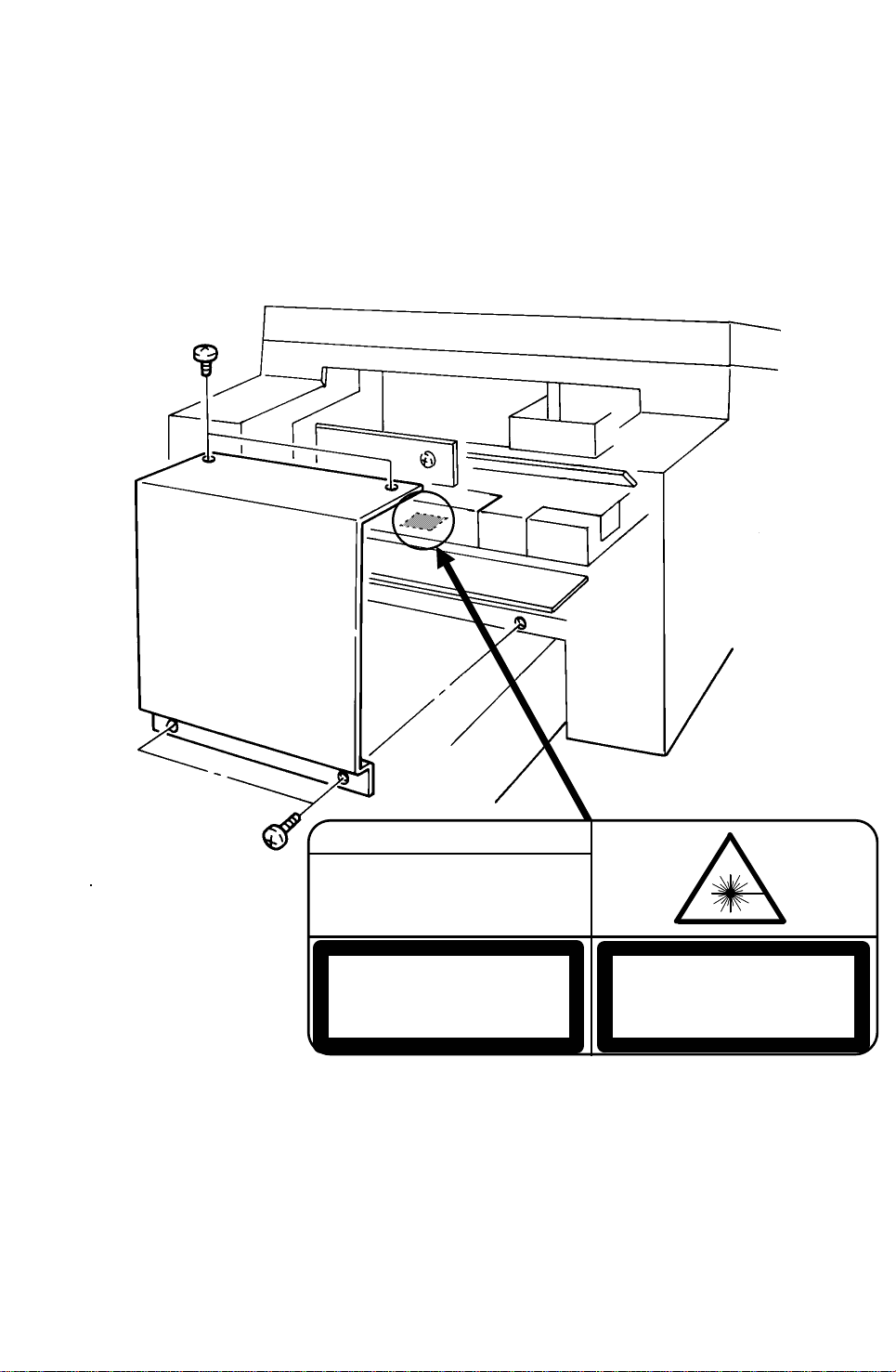
DANGER
INVISIBLE LASER RADIATION
WHEN OPEN AVOID DIRECT
EXPOSURE TO BEAM
CAUTION
LASER RADIATION WHEN
OPEN AVOID EXPOSURE
TO BEAM
VORSICHT
UNSICHTBARE LASERSTRAHLUNG,
WENN ABDECKNG GEOFFNET
NICHT DEM STRAHL AUSSETZEN
Lithium Batteries (Memory Back-up)
CAUTION:
The danger of explosion exists if a battery of this type is incorrectly replaced.
Replace only with the same or an equivalent type recommended by the
manufacturer. Discard used batteries in accordance with the manufacturer’s
instructions.
Page 3

OVERALL MACHINE INFORMATION 3rd May, 1994
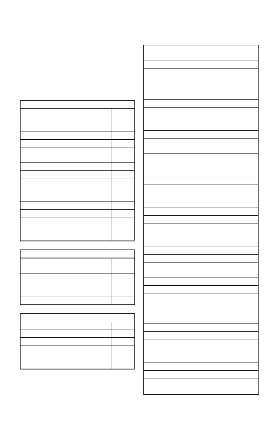
SPECIFICATIONS
1. OVERALL MACHINE INFORMATION
1.1. SPECIFICATIONS
Type
Desktop transceiver
Circuit
PSTN, PABX, ISDN (Option)
Connection
Direct couple
Document Size
Length: 105 - 1200 mm [4.1 - 47.2 ins]
Up to 100 m [328 ft] after adjustment
Width: 148 - 304 mm [5.8 - 12.0 ins]
Thickness: 20 lb paper 0.05 to 0.2 mm
[2 to 8 mils]
Manual Feed 0.04 to 0.4 mm
[1.6 to 16 mils]
Document Feed
Automatic feed, face down
ADF Capacity
50 sheets (using 20 lb paper)
Scanning Method
Flat bed, with CCD
Protocol
Group 3 with ECM, Group 4 kit available
Data Rate
G3: 14,400/12,000/9,600/7,200/4,800/2,400
bps; automatic fallback
G4: 64 kbps/56 kbps
I/O Rate
With ECM: 0 ms/line
Without ECM: 2.5, 5, 10, 20, or 40 ms/line
Transmission Time
G3: 6 s at 14,400 bps with ECM for a CCITT
#1 test document (Slerexe letter) using
standard resolution
G4: 3 s at 64 kbps for a ITU - T#1 test document using detail resoultion.
Printing System
Laser printing, using the Ricoh CS (Compact
Seamless) Engine, plain paper, dry toner
Paper Size
Standard Cassette: Letter, Legal, A4, B4,
A5, B5
Lower Cassette: Letter, Legal, A4, B4
Information
Overall Machine
Maximum Scan Width
296 mm [11.7 ins] ± 1%
Scan Resolution
Main scan: 400dpi / 200 dpi
Sub scan:
Standard 200 x100 dpi
Detail 200 x 200 dpi
Fine 200 x 400 dpi
Super Fine 400 x 400 dpi
Memory Capacity
ECM: 128 kbytes (double buffer)
SAF: Base machine - 1 Mbyte (56 pages),
with optional extra 1 Mbyte or 2 Mbytes
(max 112 or 168 pages respectively), or 40
Mbyte hard disk (1,200 pages total)
Compression
G3: MH, MR, EFC, MMR, SSC
Storage to SAF memory for tx: MH
MMR only with ECM
G4: MH, MR, MMR
Modulation
V.33/V.17 (TCM), V.29 (QAM), V.27ter
(PHM), V.21 (FM)
Maximum Printout Width
250 mm [9.8 ins]
Maximum Printer Resolution
Main scan: 400 dpi
Sub scan: 400 dpi
Power Supply
115 ± 20 Vac, 60 ± 1 Hz
Power Consumption (Base Machine Only)
Standby: 51 W Transmit: 51 W
Receive: 193 W Copying: 282 W
Operating Environment
Temperature: 17 - 28 °C [63 - 82 °F]
Humidity: 40 - 70 %Rh
Dimensions (W x D x H)
516 x 474 x 308 mm [20.3 x 18.7 x 12.1 ins]
Excluding handset, trays, cassettes, and optional units
Weight
Approx. 22 kg [48.5 lbs]
Excluding CTM and optional units
1-1
Page 4
3rd May, 1994 OVERALL MACHINE INFORMATION
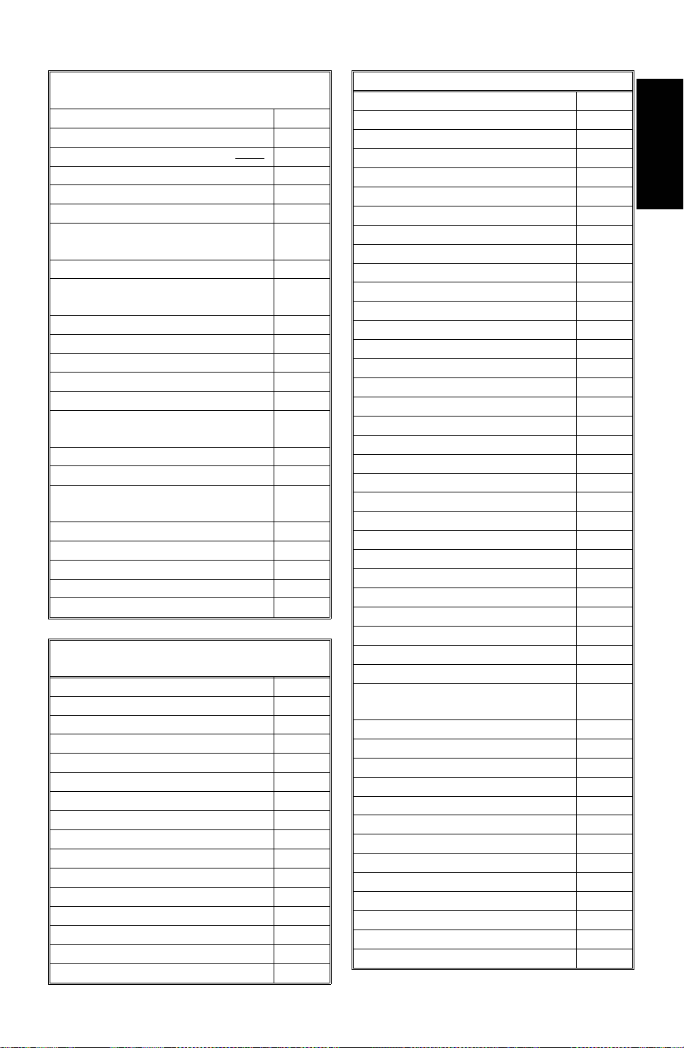
FEATURES
1.2. FEATURES
KEY: O = Used, X = Not Used,
A = With optional memory or hard disk only,
B = With lower cassette only,
C = With Group 4 kit only,
D = With optional handset only
E = With 400dpi page memory only
F = With printer interface only
Equipment
ADF O
Bar code reader X
Built-in handset X
Cabinet X
Connection for ans. machine X
Connection for handset O
Cutter X
Handset (option only) O
Hard disk (option only) O
Magnetic card reader X
Manual feed mechanism O
Marker O
Microphone X
Monitor speaker O
Printer interface option O
Remaining memory indicator O
Speakerphone X
Video Processing Features
Contrast O
Halftone (Basic & Error Diffusion) O
MTF O
Reduction O
Resolution O
Smoothing to 16 x 15.4 l/mm O
Communication Features - Auto
Automatic fallback O
Automatic redialing O
Confidential reception A
Dual Access O
Substitute reception O
Transmission Reserve X
Communication Features -
User Selectable
Action as a transfer broadcaster A
AI Redial O
Alternative Destination X
Answering machine X
Authorized Reception O
Auto-answer delay time X
Auto dialing (pulse or DTMF) O
Auto Document O
Automatic Voice Message X
Auto-note X
Batch Transmission (max 50
batches)
Broadcasting O
Chain Dialing O
Communication Result Display O
Confidential ID Override O
Confidential Transmission O
Direct Fax Number Entry O
Economy Transmission O
Economy Transmission Time O
Forwarding (5 stations) A
Free Polling O
Groups (10 groups) O
Group Transfer Station O
Hold X
ID Transmission Option O
Immediate Redialing O
Immediate transmission O
Keystroke Programs O
Mailbox X
Memory transmission (this is the
default mode)
Multi-step Transfer O
Next Transfer Station C
Notify X
OMR O
On Hook Dial O
Ordering Toner O
Page Count O
Personal Codes O
Personal Codes with Conf ID O
Polling Reception O
Polling Transmission O
O
O
1-2
Page 5
OVERALL MACHINE INFORMATION 3rd May, 1994
FEATURES
Communication Features -
User Selectable
Polling tx file lifetime in the SAF O
Quick Dial (64 stations) O
Reception modes (Fax, Tel,
Reduction O
Remote control features X
Remote Transfer X
Restricted Access (50 codes,
without cards)
Secured Polling O
Secured Polling with Stored ID
Override
Secure Transmission O
Send Later O
Silent ringing detection X
Specified Image Area O
Speed Dial (100 stations) O
Super Fine Resolution
(400 X 400 dpi)
Telephone Directory O
Tonal Signal Transmission O
Transfer Request with Tonal
Signals
Transmission Deadline O
Turnaround Polling X
Two-step Transfer C
Two in one O
Voice Request (immed. tx only) D
Communication Features -
Service Selectable
AI Short Protocol O
Auto-reduction override option O
Busy tone detection O
Closed Network (tx and rx) O
Continuous Polling Reception O
Dedicated tx parameters O
ECM O
EFC O
Inch-mm conversion O
MV1200 compatibility X
Page retransmission O
Page separation mark O
Protection against wrong conn. O
Resol’n stepdown override option X
Short Preamble O
Well log O
Auto) O
Other User Features
Area Code Prefix O
Auto Service Call O
Center mark O
Checkered mark O
Clearing a memory file O
Clearing a polling file O
Clock O
O
O
E
O
Confidential ID O
Copy mode O
Copy Mode Restriction Service
Counters O
Country code O
Destination Check O
Direct entry of names O
File Retention Time O
File Retransmission O
Function Programs O
ID Code O
Label Insertion O
Language Selection O
LCD contrast control Service
Memory Lock A
Memory Lock ID A
Modifying a memory file X
Multi Sort Document Reception A
Multicopy mode A
Power Saver (Night Timer) O
Own telephone number O
Printing a memory file O
RDS on/off O
Reception Mode Switching Timer X
Reception Time (non-memory rx
only)
Remote ID O
Reverse Order Printing A
RTI, TTI, CSI O
Secure ID X
Service Report Transmission O
Speaker volume control O
Specified Cassette Selection B
Substitute reception on/off O
Telephone line type O
TTI on/off O
User Function Keys O
User Parameters O
Wild Cards O
O
Information
Overall Machine
1-3
Page 6
3rd May, 1994 OVERALL MACHINE INFORMATION
FEATURES
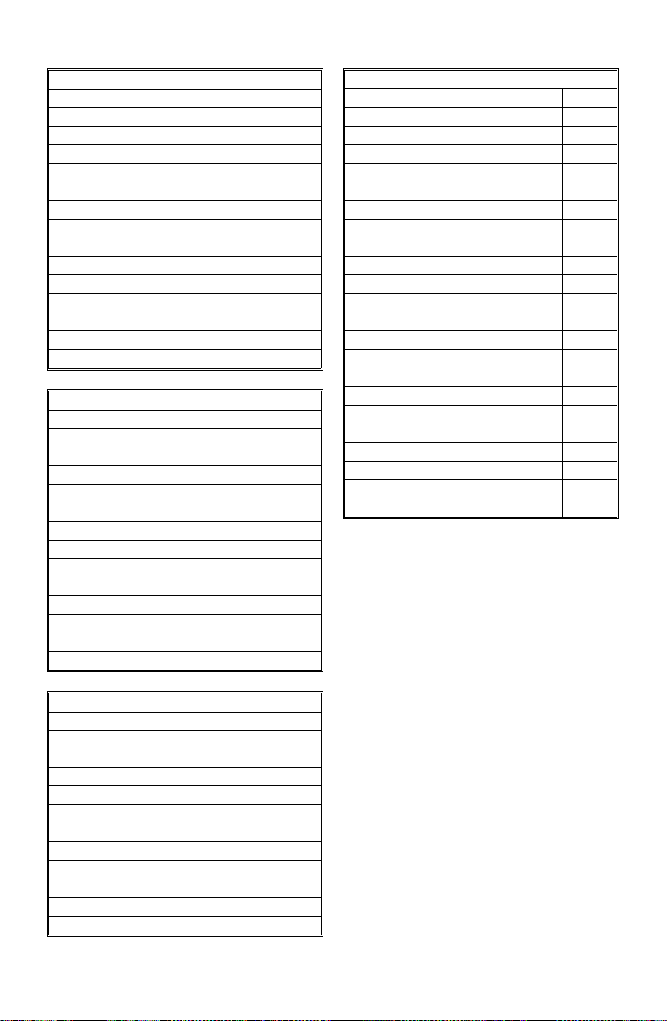
Reports - Automatic
Charge Control Report X
Communication Failure Report O
Confidential File Report O
Error Report O
Memory Storage Report O
Mode Change Report X
Polling Clear Report O
Polling Reserve Report O
Polling Result Report O
Power Failure Report O
TCR O
Toner Cassette Order Form O
Transfer Result Report O
Transmission Deadline Report O
Transmission Result Report O
Reports - User-initiated
Authorized Reception List O
Charge Control Report X
File List O
Forwarding List A
Group List O
Personal Code List O
Program List O
Quick Dial List O
Specified Cassette Selection List B
Speed Dial List O
TCR O
Transmission Status Report X
User Function List O
User Parameter List O
Service Mode Features
Memory file printout (all files) O
Modem test O
NCU parameters O
Operation panel test O
Printer mechanism test X
Printer test patterns O
Programmable attenuation X
Protocol dump list O
RAM display/rewrite O
RAM dump O
RAM test O
Ringer test X
Scanner lamp test O
Scanner mechanism test O
Sensor initialization X
Serial number O
Service monitor report O
Service station number O
Status Sheet F
System parameter list O
Technical data on the TCR O
Thermal head parameters X
Transmission Status Report X
Memory Files
Max. number of files: 200
Max. number of stations/file: 200
Max. number of stations overall: 500
Max. number of pages overall: 1,200
Service Mode Features
Back-to-back test O
Bit switch programming O
Buzzer test O
Cable equalizer O
Comm. parameter display O
Counter check O
DTMF tone test O
Echo countermeasure O
Error code display O
File Transfer O
Hex Dump List F
LCD contrast adjustment O
1-4
Page 7
20
23
24
14
19
OVERALL MACHINE INFORMATION 3rd May, 1994
COMPONENT LAYOUT
1.3. COMPONENT LAYOUT
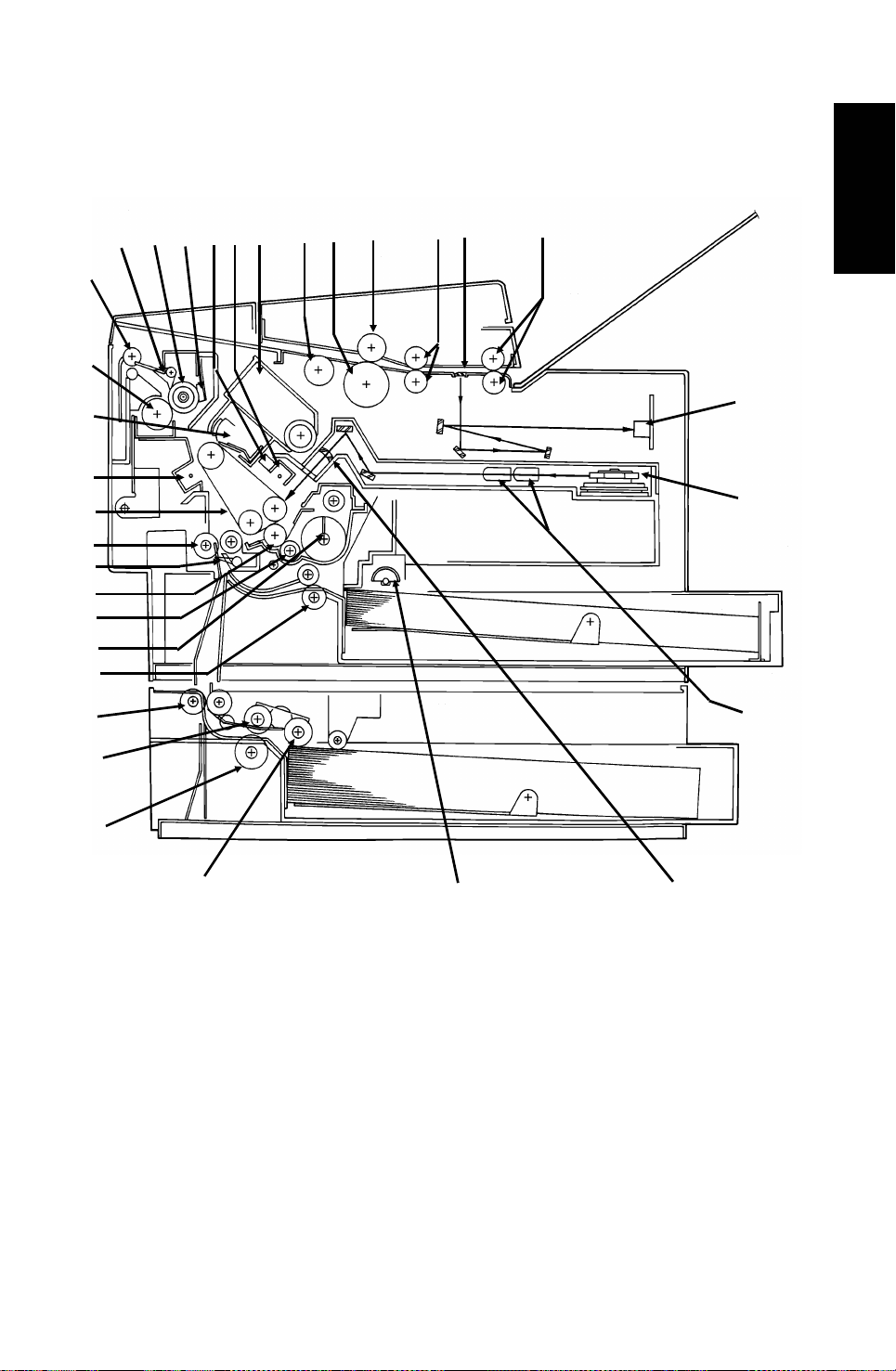
1.3.1. Mechanical Components
13
15
16
17
18
21
22
12
11
10
2
6789
45
3
1
32
31
30
Information
Overall Machine
25
26
27
1. R2 Rollers Feed the document through the scanner.
2. Exposure Glass Exposes the original to light from the xenon lamp.
3. R1 Rollers Feed the document through the scanner.
4. Separation Roller Allows one page into the scanner.
5. Document Feed Roller Feeds the document into the scanner.
6. Pick-up Roller Picks up pages of the document from the document
table.
7. Toner Cartridge This supplies toner to the development unit. It is part of
the CTM (Cleaning/Toner Magazine).
8. Charge Corona Unit This applies a charge to the master at the start of the
print cycle.
9. Quenching Lamp This removes excess charge from the master at the end
of the print cycle.
10. Thermistor This measures the temperature in the fusing unit.
11. Hot Roller Heat from this roller fuses the toner to the copy paper.
28
29
1-5
Page 8

3rd May, 1994 OVERALL MACHINE INFORMATION
COMPONENT LAYOUT
12. Hot Roller Strippers These take the paper off the hot roller after fusing.
13. Copy Feed-out Rollers These feed the paper out of the printer.
14. Pressure Roller (Fusing) This applies pressure to the paper during the fusing
process.
15. Cleaning Unit/Used Toner
Tank
16. Transfer Corona Unit This applies a charge to the paper to pull the toner off
17. Master Belt Also known as the CS (Compact Seamless) Engine.
18. Registration Roller This carries out the registration process.
19. Registration Sensor This detects when paper is approaching the registration
20. Development Roller This roller applies toner to the latent image on the
21. Toner Supply Bar This feeds toner to the development roller.
22. Toner Mixing Bar This stirs up the toner in the development unit, so that it
23. Upper Relay Rollers These feed paper from the upper cassette into the
24. Lower Relay Rollers These feed paper from the lower cassette into the
25. Lower Paper Feed Roller This feeds paper out of the lower cassette.
26. Lower Paper Separation
Roller
27. Lower Paper Pick-up
Roller
28. Upper Paper Feed Rollers These pick up the top sheet of paper from the stack in
29. Focusing Lens This focuses the laser beam onto the master belt.
30.
Fθ Lenses
31. Hexagonal Mirror This passes the laser beam across the master belt.
32. CCD (Charge Coupled
Device)
This removes excess toner from the master after image
transfer and stores it. It is part of the CTM
(Cleaning/Toner Magazine).
the master and onto the copy paper.
The latent image is written to this organic
photoconductor belt.
roller.
master belt.
does not collect into lumps.
printer.
printer.
This ensures that only one sheet of paper at a time
leaves the lower cassette.
This picks up the top sheet of paper from the stack in
the lower cassette and passes it to the feed roller.
the upper cassette and feed it into the printer.
These ensure that the thickness of the laser beam is
uniform across the main scan.
This converts the light reflected from the document into
an analog video signal.
1-6
Page 9
567
13
14
OVERALL MACHINE INFORMATION 3rd May, 1994
COMPONENT LAYOUT
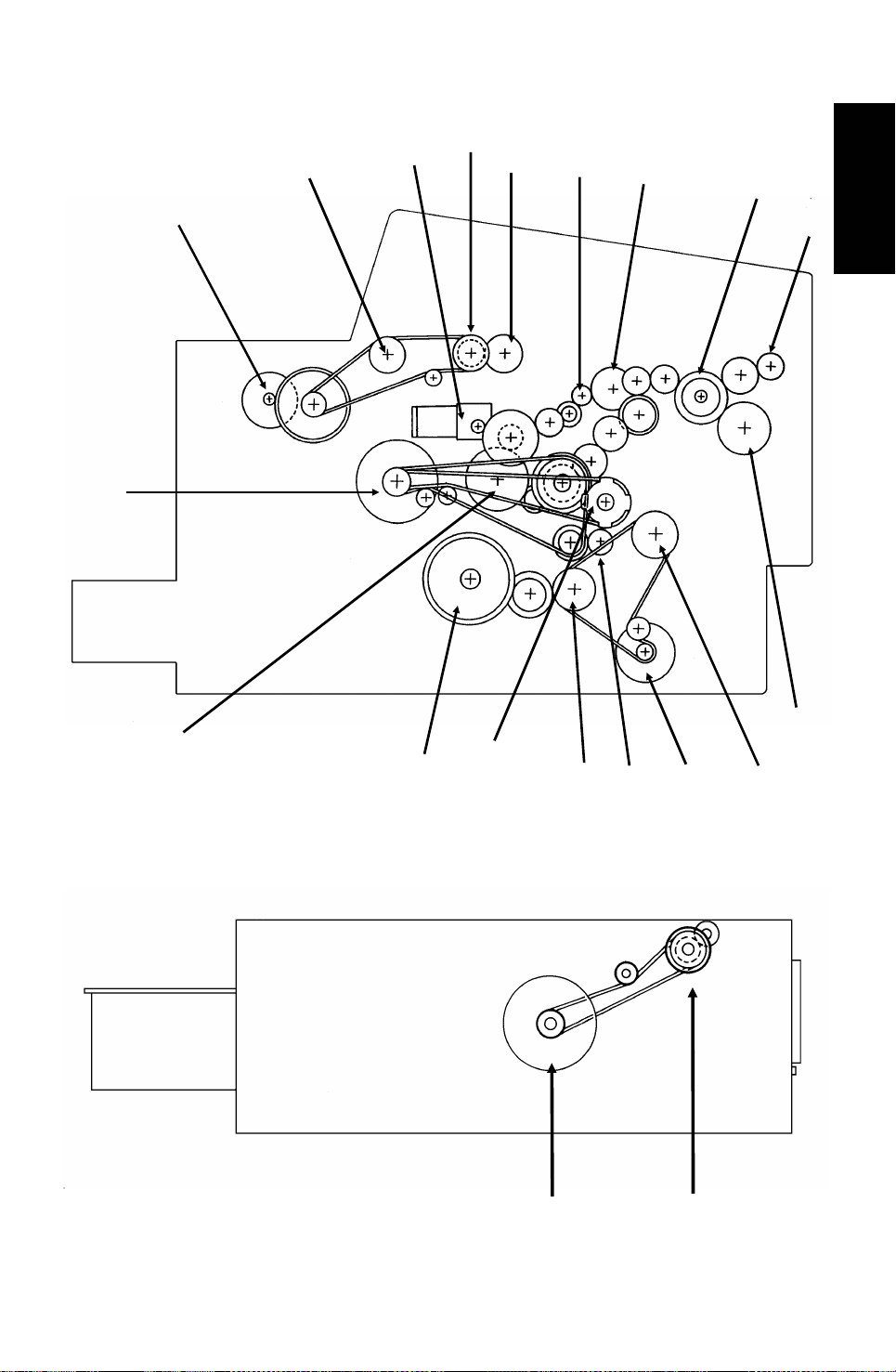
1.3.2. Drive Components
2
3
4
8
18
17
1
16
15
12
11
10
9
Information
Overall Machine
1-7
19
20
Page 10

3rd May, 1994 OVERALL MACHINE INFORMATION
COMPONENT LAYOUT
1. Tx Motor This stepper motor drives the scanner.
2. R2 Roller This feeds the original through the scanner.
3. Toner Supply Motor This dc motor drives the toner supply mechanism.
4. R1 Roller This feeds the original through the scanner.
5. Shutter Drive Gear This ensures that the shutter moves out of the
document feed path at the correct time.
6. Toner Supply Gear (CTM) This ensures the supply of toner from the CTM into the
development unit. It is part of the CTM.
7. Cleaning Brush Drive Gear This drives the cleaning brush in the CTM.
8. Hot Roller This fuses the toner to the copy paper.
9. Copy Feed-out Roller This feeds printouts out of the machine.
10. Pressure Roller This applies pressure to the copy paper in the fusing
unit.
11. Registration Roller Drive
Gear
12. Upper Paper Feed Motor This drives the paper feed mechanism in the upper
13. Development Roller Drive
Gear
14. Upper Paper Feed Roller
Drive Gear
15. OPU Drive Pulley This drives the master belt.
16. Paper Feed Clutch This transfers drive from the upper paper feed motor to
17. Toner Supply Gear
(Development)
18. Main Motor This brushless dc motor drives the master belt, fusing
19. Lower Paper Feed Motor This drives the paper feed mechanism in the lower
20. Lower Paper Feed Clutch This transfers drive from the lower paper feed motor to
This drives the registration roller.
cassette.
This drives the development roller.
This drives the upper paper feed roller.
the upper paper feed mechanism.
This ensures the collection of toner from the CTM, and
its distribution across the full length of the development
unit.
unit, development unit, and cleaning unit.
cassette.
the lower paper feed mechanism.
1-8
Page 11
16
OVERALL MACHINE INFORMATION 3rd May, 1994
COMPONENT LAYOUT
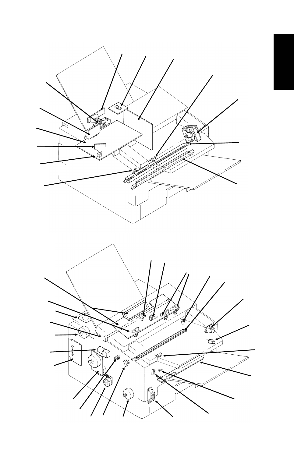
1.3.3. Electrical Components
11
10
12
1
13
9
8
2
3
4
Information
Overall Machine
5
6
7
37
36
34
32
33
31
35
30
29
28
27
26
14
15
25
17
18
19
20
21
22
23
24
1-9
Page 12
3rd May, 1994 OVERALL MACHINE INFORMATION
COMPONENT LAYOUT
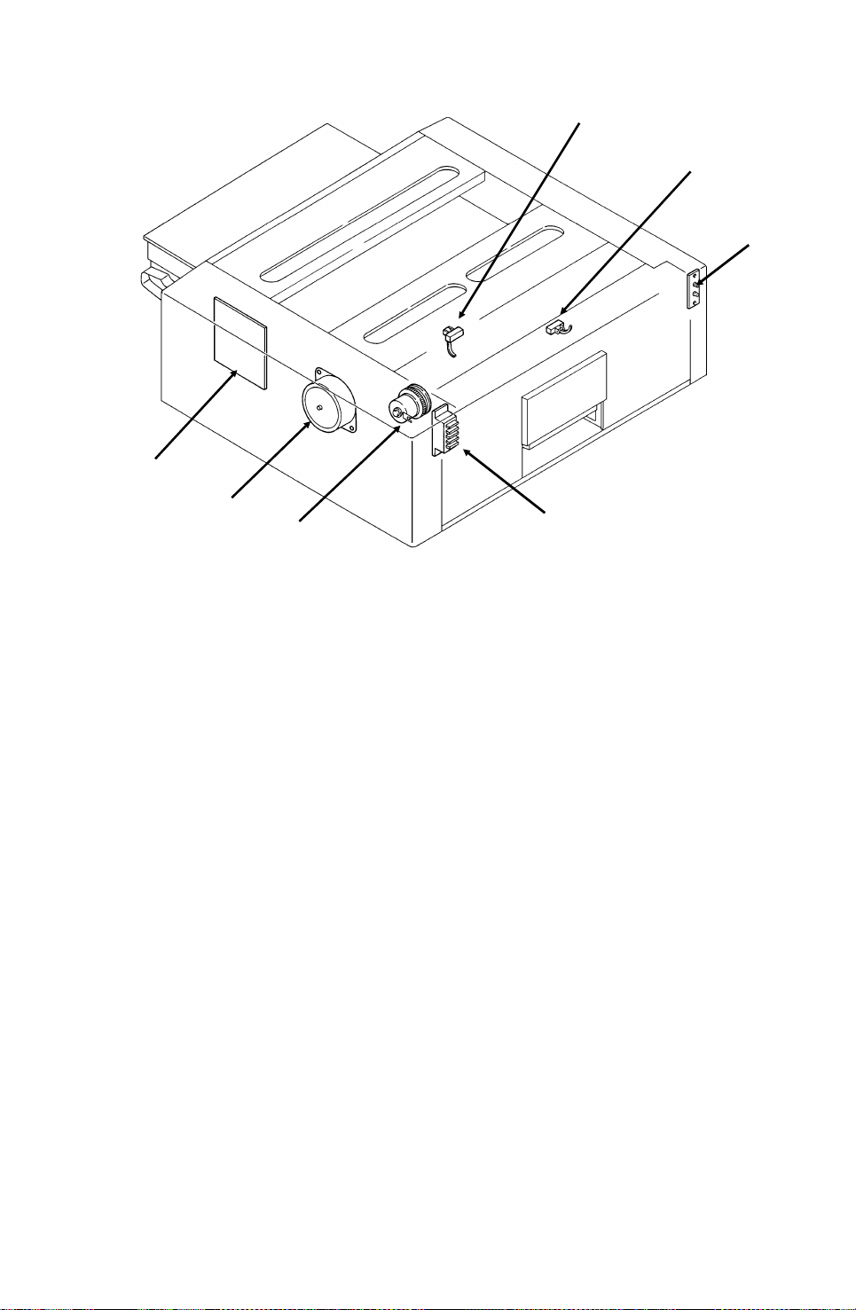
Lower Cassette
44
43
42
Name Description No.
PCBs
FCU This board controls the machine. 11
MBU This board contains the system ROM and RAM for storing
system parameters such as bit switch settings and programmed
telephone numbers.
SBU This board contains the CCD. 1
OP-PORT This board controls the operation panel. 37
NCU This board contains relays and switches for interfacing the
machine to the network and the handset.
PSU This board supplies power to the machine. 3
LD Unit This board drives the laser diode. 10
PFU This board controls the lower paper feed unit. 44
MOTORS
Tx Motor This stepper motor drives the scanner. 33
Main Motor This dc motor drives the fusing unit, master belt, development
roller, and cleaning unit.
Upper Paper
Feed Motor
Lower Paper
Feed Motor
Toner Supply
Motor
Hexagonal Mirror
Motor
Ozone Fan This removes ozone-laden air from the vicinity of the master
CLUTCHES
This stepper motor drives the upper paper feed mechanism and
the registration roller.
This stepper motor drives the lower paper feed mechanism. 43
This dc motor drives the toner supply mechanism. 32
This high-speed dc motor drives the hexagonal mirror in the
laser printer optics.
unit, and filters out the ozone.
38
39
40
41
12
31
30
26
13
5
1-10
Page 13

OVERALL MACHINE INFORMATION 3rd May, 1994
COMPONENT LAYOUT
Name Description No.
Upper Paper
Feed Clutch
Lower Paper
Feed Clutch
SENSORS
Document Sensor This detects the presence of a document in the feeder. 36
Scan Line Sensor This detects when a page is approaching the auto shading
Document Width
Sensor
Toner Near-end
Sensor
Upper Paper
Size Detector
Upper Paper End
Sensor
Registration
Sensor
Paper Feed-out
Sensor
Front Cover
Switch
CTM Sensor This detects when a CTM has been installed in the machine. 27
Lower Paper
Size Detector
Lower Paper End
Sensor
Lower Paper
Feed Sensor
INTERLOCK SWITCHES
Front Cover
Interlock
Switches
OTHERS
Speaker This allows the user to listen to the condition of the telephone
Xenon Lamp This lamp illuminates the document. 34
Xenon Lamp
Driver
Charge Corona
and Quenching
Lamp Unit
Transfer Corona
Unit
Varistor This ensures that the charge given to the master by the charge
Marker This stamps a red circle on each page that is successfully fed
This transfers drive from the upper paper feed motor to the
paper feed roller in the upper cassette.
This transfers drive from the lower paper feed motor to the
paper feed roller in the lower cassette.
position.
This detects when a B4-width [10.1"] or A3-width [11.7"]
document has been placed in the feeder.
This detects when the toner has almost run out. 17
This detects the paper size installed in the upper cassette. The
user must install the correct actuator.
This detects when the paper in the upper cassette has run out. 29
This detects when paper has arrived at the registration rollers. 21
This detects when the paper has been fed out of the printer. 24
This detects whether the front cover is open or closed. 23
This detects the paper size installed in the lower cassette. The
user must install the correct actuator.
This detects when the paper in the lower cassette has run out. 38
This sensor detects the presence of paper at the lower paper
feed roller.
If the front cover is open, these interlock switches interrupt the
+5VLD power supply for the laser diode and the +24VD power
supply for the power pack, motors, and other components.
line.
This drives the xenon lamp. 2
The charge corona unit charges the master belt at the start of
the print cycle. The quenching lamp removes excess charge
from the master belt at the end of the print cycle.
This pulls the toner off the master and onto the copy paper. 7
corona wire does not exceed -750 Volts.
through the scanner.
28
42
14
16
25
41
39
19,
20
35
18
9
15
Information
Overall Machine
1-11
Page 14

3rd May, 1994 OVERALL MACHINE INFORMATION
COMPONENT LAYOUT
Name Description No.
Power Pack This supplies high voltages to the corona wires and the
development bias terminal.
Fusing Lamp This fuses the toner to the paper. 6
Thermistor This monitors the temperature inside the fusing unit. 8
Thermostat This interrupts the ac power supply to the fusing lamp if the
temperature exceeds 400 °C.
Lower Cassette
Indicator Panel
This contains indicators to show the status of the lower cassette. 40
22
4
1-12
Page 15
OVERALL MACHINE INFORMATION 3rd May, 1994
OVERALL MACHINE CONTROL
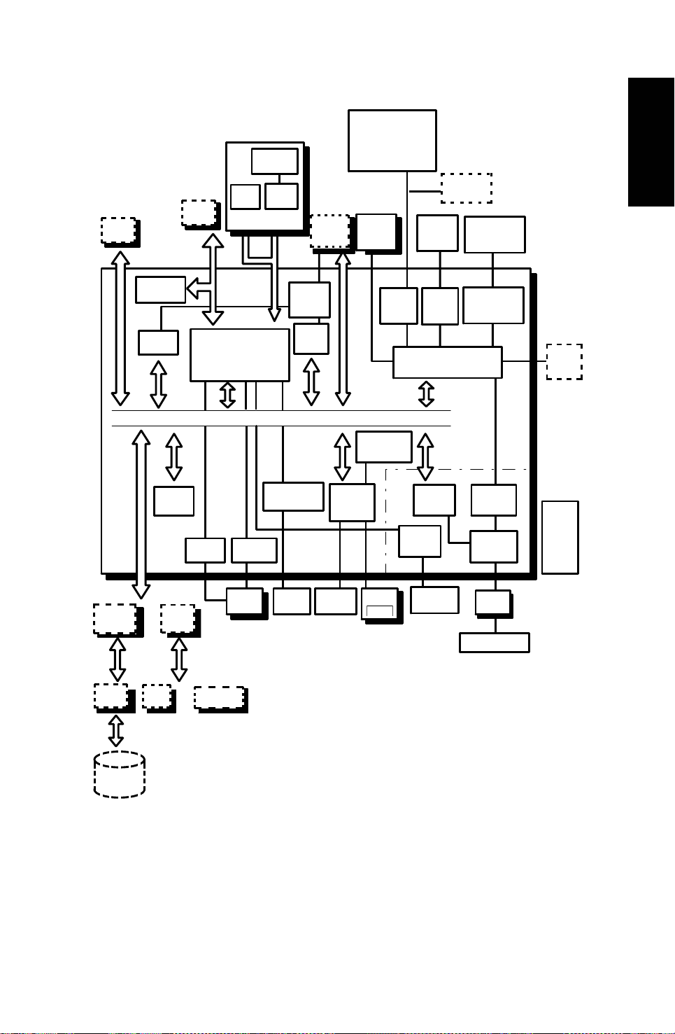
1.4. OVERALL MACHINE CONTROL
Xenon Lamp
Stamp
Ozon Fan
CIG4
PMU
ROM
Back up
(SYS)
SRAM
MBU
IC
Card
Eraser
Electrical Clutch
OP-
PORT
Motors
Optional
Counter
Thermistor
Information
Overall Machine
FCU
Page
memory
DRAM
FONT
ROM
or
LDAMP
OPIFOPHDIF
MFCP50
(FCP, LIF, QPCR)
DATA ADDRESS BUS
LDDUTY
LDDR
Back-up
(SAF)
SAF
Comparator
(LDS)
Laser
Diode
VPP50
Sensors
Driver
Video
Processing
memory
SBU
CCD
PWM
Circuit
Monitor
Speaker
MFPD
IOP
Analog Part
R144
EFXL
Comparator
(THRM)
DTMF
Receiver
Analog
Circuit
NCU
Handset
PFU
PSU
HDIF
40MBHDD
PIF
or
RS232C
The cpu on the FCU board controls the machine, as shown in the above
drawing.
There is no modem board in the machine; the modem consists of a chip on
the FCU board that carries out all the analog and digital functions of a fax modem.
1-13
Page 16
3rd May, 1994 OVERALL MACHINE INFORMATION
VIDEO DATA PATH
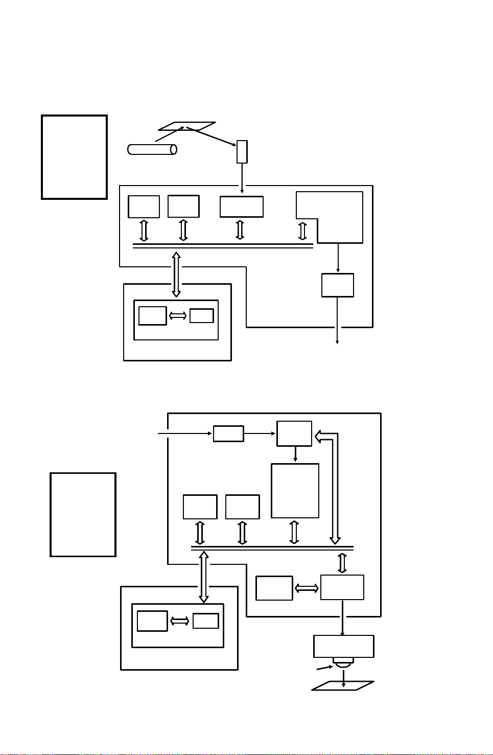
1.5. VIDEO DATA PATH
1.5.1. Transmission
Original
Reference:
Group 3
Facsimile
Manual,
section
1-3-1
Xenon
Lamp
ECM
Memory
Line
Buffer
SAF
Memory
RAM
MBU
FIFO
Video
Processor
The following diagrams show
the data path for this model.
There is no programmable resis-
CCD
Analog Signal
Modem
FCU
Network
(via the NCU)
tor in this model.
CPU
To the
1.5.2. Reception
From the
Network
(via the NCU)
Reference:
Group 3
Facsimile
Manual,
section
1-3-2
Line
Buffer
RAM
MBU
FCU
Memory
SAF
FIFO
Filter
ECM
Memory
Page
Memory
Laser Diode
Modem
CPU
Laser
Interface
Laser Diode
Driver
1-14
Copy Paper
Page 17
OVERALL MACHINE INFORMATION 3rd May, 1994
POWER DISTRIBUTION
1.6. POWER DISTRIBUTION
1.6.1. Distribution Diagram
Lower Paper Feed Motor
Lower Paper Feed Clutch
+24VD
Information
Overall Machine
AC Main
Power
Fusing
Lamp
Front Cover
Interlock Switch
PSU
AC Switching
Circuit
+24V
-12V
+24VS
+24VD
+5V
Scanner
Sensors
+5V
Operation
Panel
+5V
-12V
+24VD
+5V
+5VLD
+24VD
+5V
Regulator
Regulator
PFU
- 12V
+24VS
+5V
+5V
+24VS
FCU
- 5V
+12V
NCU
Sensors and
Indicators
FUSING UNIT
Thermistor
+5V
+5V, +5VD
+5V
SAF Memory
+5V
SBU
+12V
+5V
Printer
Sensors
+5V, +12V
-12V, +24VS
+5V, -12V
+24VS
+5V, +24VS
Memory
Card
MBU
Printer
Interface
CIG4
Hard Disk
Front Cover
Microswitch
+5VLD
LDDR
Laser Diode
+5V
+5V
+24VD
Motors, Clutches, Lamps,
Marker, Power Pack,
Optional counter
Optional
Page Memory
RS-232C
Interface
The laser diode is powered by a special +5V supply, called +5VLD.
There are two +24V power supplies:
• +24VS: This is always on when the main switch is on.
• +24VD: This is interrupted if the front cover interlock switch opens.
There is no +24VD activation signal from the cpu to the PSU.
1-15
Page 18
3rd May, 1994 OVERALL MACHINE INFORMATION
POWER DISTRIBUTION
1.6.2. Memory Back-up Circuit
Reference:
Group 3
Facsimile
Manual,
section 1-4-3,
Circuit type 1
+5V
Voltage
Detector
+24V
[A]
+5V
Switching
Circuit
Regulator
MBU
RAM
1-9
1-7
Battery
Switch
Battery
Switching
Circuit
FCU
CN12-33
CN12-29
Real Time
Clock
CPU
Memory
Monitor
SAF
Memory
[B]
Battery
The battery [A] on the MBU backs up the RAM on the MBU, which contains
system parameters. It also backs up the real time clock in the cpu. This battery is not rechargeable. CN1-7 tells the cpu whether the back-up power
(CN1-9) comes from the battery or from the +5V power supply.
There is no battery switch for the battery on the FCU.
A rechargeable battery [B] on the FCU board backs up the SAF memory and
the real time clock for 1 hour. While the main power is on, the +24V supply recharges the battery.
If there is data in the SAF memory, the rechargeable battery [B] also backs
up the real time clock, to preserve the MBU battery.
1-16
Page 19
DETAILED SECTION DESCRIPTIONS 3rd May, 1994
SCANNER
2. DETAILED SECTION DESCRIPTIONS
2.1. SCANNER
2.1.1. Mechanisms
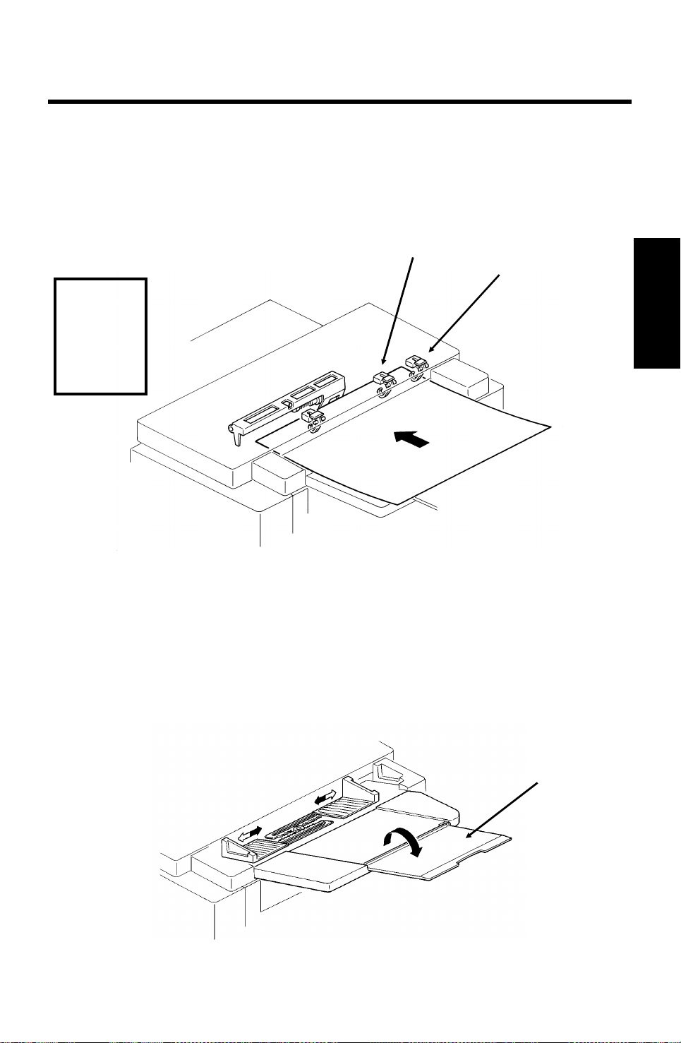
1. Document Detection
[A]
Document Table
Reference:
Group 3
Facsimile
Manual,
section
2-1-1.
[B]
Descriptions
Detailed Section
• Scanning speed of an A4 document is as follows.
- Standard resolution … 1.5 sec
- Detail resolution … 3.0 sec
- Fine resolution … 6.0 sec
• The scanner is A3-width [11.7"], with a B4 document width detector [A]
and an A3 document width detector [B].
• The scanner contains a xenon lamp.
•
There is a fold-down extension [C] to support long documents.
[C]
2-1
Page 20
Reference:
Group 3
Facsimile
Manual, section
2-1-1.
3rd May, 1994 DETAILED SECTION DESCRIPTIONS
SCANNER
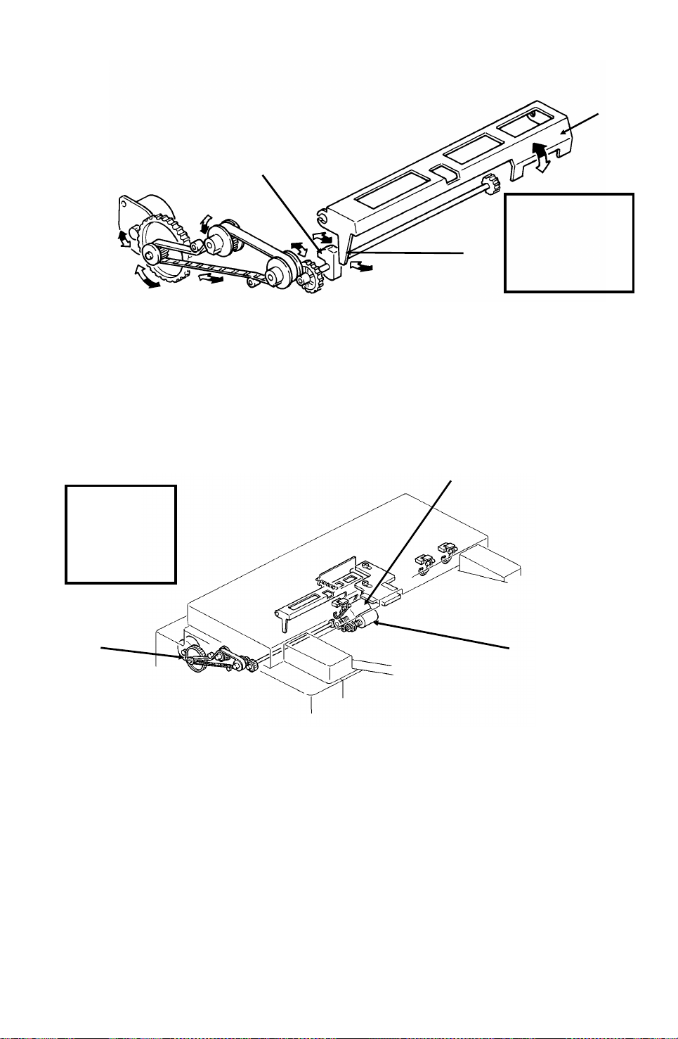
Shutter
[C]
[B]
[A]
In standby mode, tab [A] rests on cam [B]. When the tx motor starts, the motor rotates forwards (white arrows), the cam lifts the tab, and the shutter [C]
rises. After the last page has been fed through the scanner, the tx motor reverses (black arrows), the cam drops back to the standby position, and the
shutter blocks the scanner path again.
2. Pick-up and Feed
Drive Mechanism
Reference:
Group 3
Facsimile
Manual,
section 2-2-1.
[A]
[B]
[C]
This machine has a Mechanical Clutch Mechanism. The tx motor [A] drives
the feed roller [B] and pick-up roller [C].
Resolution
Standard - Immediate transmission: The tx motor feeds the document at 200 lines per inch.
The video processor executes OR processing to convert the data into 100 lines per inch.
Memory transmission: The motor feeds the document at 100 lines per inch, and no OR processing is needed.
Detail - The tx motor feeds the document at 200 lines per inch. There is no OR processing,
and the data is transmitted at 200 lines per inch.
Fine - The tx motor feeds the document and transmits data at 400 lines per inch. If the other
terminal cannot receive at this resolution, alternate lines of data are deleted, so the effective
resolution of the transmitted data is 200 lines per inch.
2-2
Page 21
DETAILED SECTION DESCRIPTIONS 3rd May, 1994
SCANNER
Jam Conditions
The cpu detects a document jam if one of the following conditions occurs.
•
The scan line sensor does not switch on within 5 s of the tx motor starting.
• The scan line sensor does not turn off after the maximum document
length has been fed since it turned on; this is 6 s (standard resolution),
12 s (detail), or 24 s (fine) for a 1.2 m long document.
• The scan line sensor switches on while the document sensor is off.
• The document width sensor switches on while the document sensor is
off.
• The scan line sensor does not turn on within 2 s of the end of stamping,
if the document sensor is on.
Separation
Reference: Group 3 Facsimile Manual, section 2-2-2
Descriptions
Detailed Section
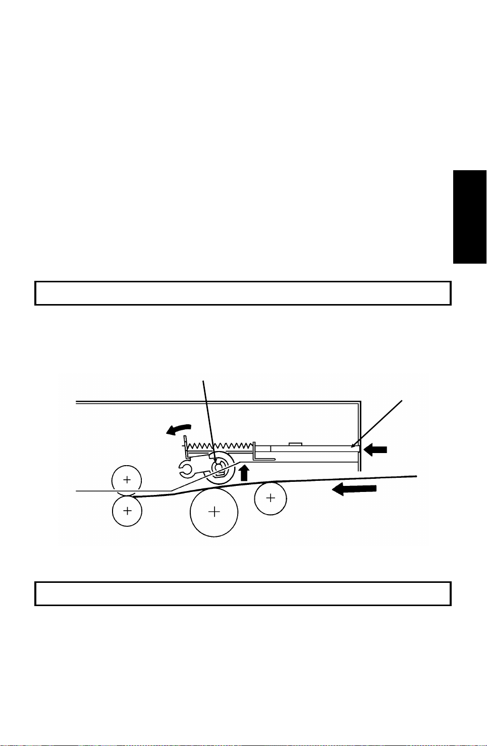
3. Manual Feed
[B]
[A]
The manual feed button [A] lifts the separation roller [B] out of the document
feed path. There is no manual feed switch.
Reference: Group 3 Facsimile Manual, section 2-2-3
2-3
Page 22
3rd May, 1994 DETAILED SECTION DESCRIPTIONS
SCANNER
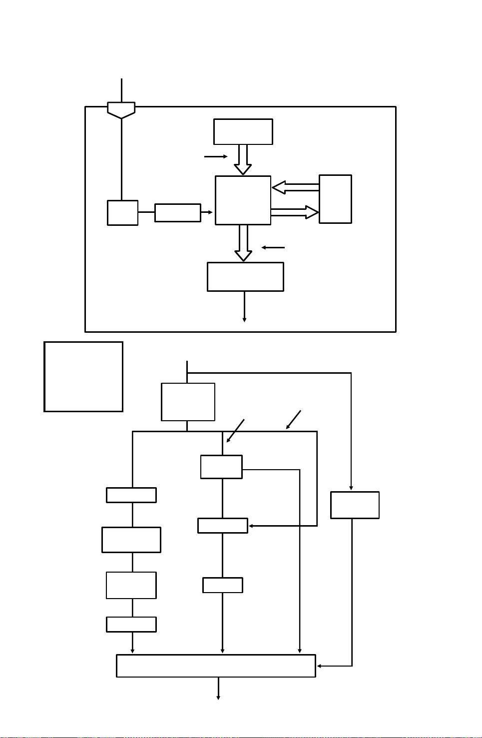
2.1.2. Video Data Processing
Output from the CCD
A
Auto Shading
Memory
WHITE
WAVEFORM
FEEDBACK
Reference:
Group 3
Facsimile
Manual,
section 2-3.
DC
Filter
VIDEO
PROCESSOR
Corrected Data from the Auto Shading Circuit
Amplifier
Gamma
Correction,
MTF
A/D
Converter
Data Processing
Circuits
Halftone
Process
Edge
Detection
To the CPU
and Modem
Basic
EDGE
ELEMENTS
Peak
Hold
CORRECTED
DATA
Error
Diffusion
Halftone
Process
Comparator
Background
Detection
OR
Processing
Reduction
A
NON-EDGE
ELEMENTS
Reduction
Halftone
B
Process Selector
To CPU and Modem
2-4
Image/Text
Detection
B’
Page 23
DETAILED SECTION DESCRIPTIONS 3rd May, 1994
PRINTER
2.2. PRINTER
2.2.1. Mechanisms
1. Master Unit
This printer uses a "write to black" system, using negative toner.
The master unit contains a durable OPC master belt. The expected lifetime of
each master unit is about 60,000 copies (this is the target value). Because of
this long lifetime, the user is not expected to change the master; there is no
Replace Master indicator.
The master belt does not have a bond seam, so no master home position detection is needed. There is also no master unit interlock switch; there is an interlock switch on the front cover.
[A]
[B]
The main motor [A] drives the master belt [B].
• At the start of printing, it turns on briefly and the master belt moves un-
der the quenching lamp to ensure that it is fully discharged.
• Then, when the fusing lamp is at the correct temperature and the page
memory contains a complete page of data, and the hexagonal mirror
motor is running at the correct speed, the main motor switches on again.
•
When the main motor is running at the correct speed, the laser diode
turns on for automatic power control.
Descriptions
Detailed Section
Reference: Group 3 Facsimile Manual, section 4-1
2-5
Page 24
[B]
3rd May, 1994 DETAILED SECTION DESCRIPTIONS
PRINTER
2. Charge Corona Unit
[D]
[E]
[A]
[C]
The charge corona unit [A] gives a -750 V charge to the master belt. The
varistor [B] ensures that the charge does not exceed this value.
The connection between the power pack [C] and the corona unit is not broken when the front cover is opened. However, the front cover interlock switch
cuts the +24V power line to the power pack if the cover is opened.
The charge corona unit contains a wire cleaner [D].
The charge corona switches on at the same time as the laser diode starts its
power control procedure.
There is one ozone fan on the right hand side of the machine. It sucks air out
of the machine through the ozone filter, which is part of the ozone fan assembly. The ozone fan switches on when a ringing signal is detected, and stays
on until the fusing lamp temperature falls back below 130 °C at the end of the
printing run.
The inset shows how the grid plate [E] connects to the varistor.
Reference: Group 3 Facsimile Manual, section 4-2
2-6
Page 25
DETAILED SECTION DESCRIPTIONS 3rd May, 1994
PRINTER
3. Laser Optics
[E]
[F]
[B]
[D]
[A]
[C]
Descriptions
Detailed Section
The optics are the same as in section 4-3-3 of the Group 3 Facsimile Manual,
except that there are two mirrors [A] at the "Second Mirror" position.
Other points to note are as follows:
• The focusing lens [B] is a barrel toroidal lens.
• The shield glass [C] prevents toner from entering the laser optics area,
and may need cleaning occasionally.
•
An optical fiber [D] passes the reflected laser beam to the main scan
start detector [E]. This detector is situated on the laser diode drive board
[F], unlike shown in the diagram.
• The strength of the beam is 0.436 mW at a wavelength of 780 nm.
• The dimensions of the dot on the master belt are 65 µm (main scan di-
rection) by 75 µm (sub-scan direction).
The charge on the exposed parts of the belt drops to about -150 V, while nonexposed areas remain at about -750 V.
The laser engine characteristics are as follows (refer to page 4-3-21 of the
Group 3 Facsimile manual for background).
• Motor speed: 9,267.7 rpm (G3 and G4 l/mm mode), 9448.8 rpm (G4 dpi
mode)
•
Motor type: Hexagonal
LD clock frequency: 5.3311 MHz
•
•
Time between main scan synchronization signals: 1.082 ms
• Number of dots per main scan: 5769
2-7
Page 26
[A]
3rd May, 1994 DETAILED SECTION DESCRIPTIONS
PRINTER
4. Development
Overview
This machine uses a ’write-to-black’ development system using negative
toner.
The toner cassette is part of a disposable unit known as the CTM (Cleaning/Toner Magazine). The CTM contains a toner cassette, toner supply
mechanism, cleaning unit, and used toner tank. When the toner is all used
up, the CTM is replaced.
Reference: Group 3 facsimile Manual, section 4-4
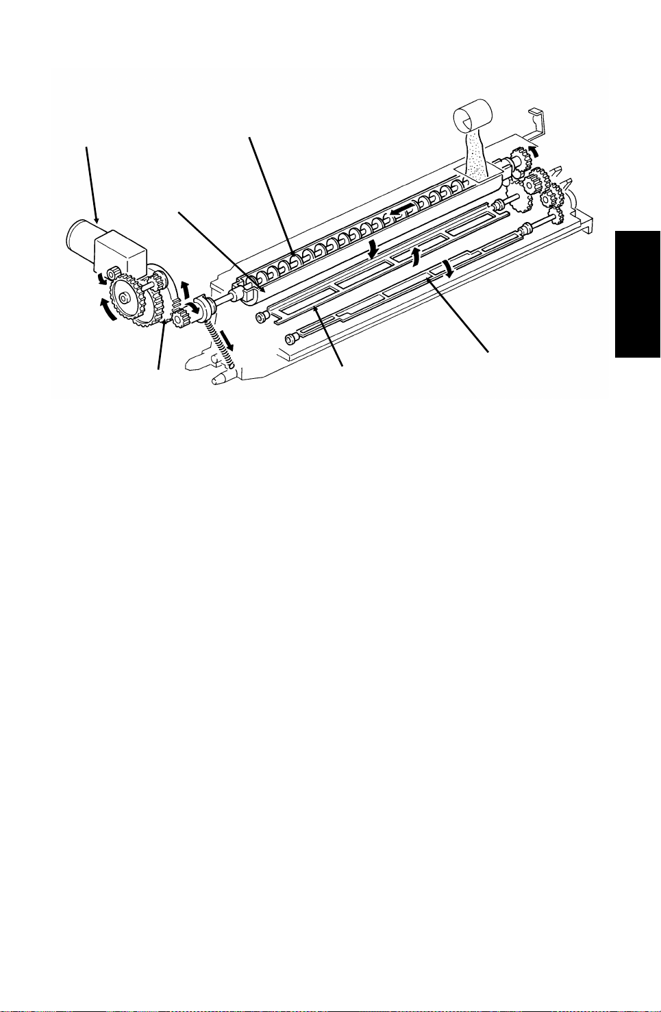
Toner Supply
[B]
[C]
[D]
[E]
When a new CTM is installed in the machine and the front cover is closed,
the main motor and toner supply motor turn on. When the front cover is
closed, a tab [A] on the fusing unit cover forces the hopper [B] to open. Also,
tab [C] on the CTM pushes bracket [D], which moves the CTM sensor actuator into the sensor.
Continued on the next page
2-8
Page 27
DETAILED SECTION DESCRIPTIONS 3rd May, 1994
PRINTER
[F]
[H]
[I] [J]
[G]
[K]
The toner supply motor [F] drives the toner supply shaft ([E] in the diagram
on the previous page). This spiral shaft feeds toner to the hopper.
Inside the development unit is another spiral shaft [G]. This shaft, driven by
the main motor, distributes toner across the length of trough [H]. The toner
supply motor drives gear [I], and once every rotation, it tips the trough upside
down, dropping the toner into the development unit. A spring immediately
pulls the trough back upright so that it can continue to receive toner.
Descriptions
Detailed Section
The toner mixing bar [J], driven by the main motor, keeps the toner agitated
as it builds up at the bottom of the development unit. The toner supply bar [K]
supplies toner to the development roller.
While toner is being supplied, the main motor is also operating the toner nearend detection mechanism. When a fresh toner cassette is installed, the sensor detects toner near-end, because there is not much toner in the
development unit. When some toner has been transferred, the signal from
the toner near-end sensor returns to normal. About 22 s after that, the toner
supply motor stops and no more toner is transferred into the development
unit.
During printing, if toner near-end is detected, the toner supply mechanism will
start up again. Toner will be supplied until the sensor signal returns to normal.
If the toner cassette in the CTM is empty, no toner will be transferred, and the
sensor signal will not return to normal. If the sensor outputs the near-end signal for more than 5 minutes, the cpu blinks the Add Toner indicator. See
"Toner Near-end Detection" for more details.
2-9
Page 28
3rd May, 1994 DETAILED SECTION DESCRIPTIONS
PRINTER
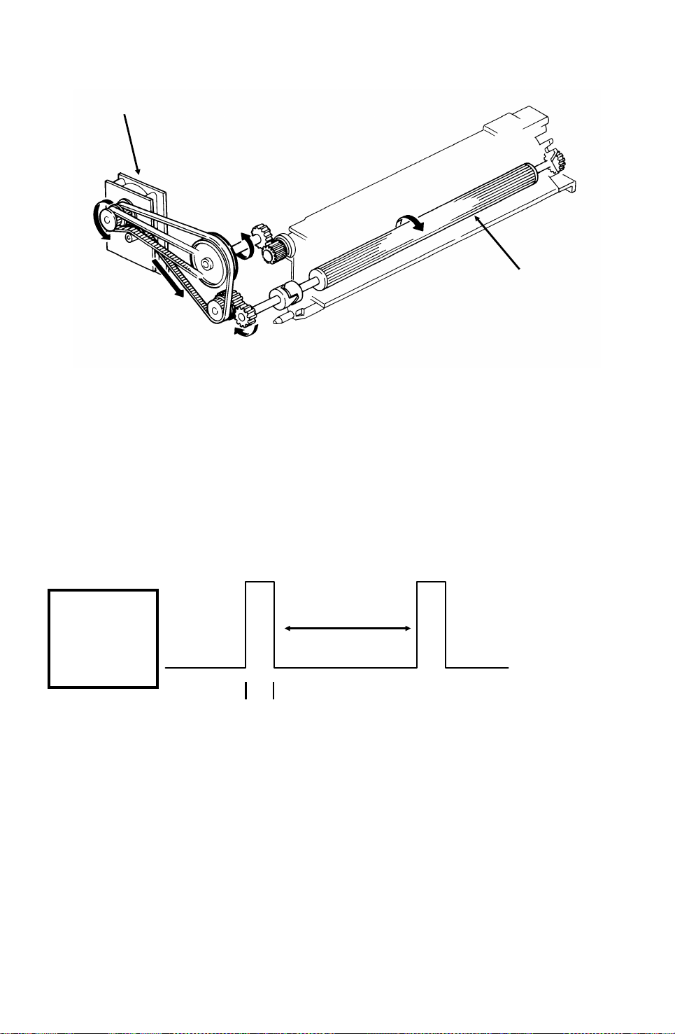
Development Unit Drive
[A]
[B]
During printing, drive from the main motor at gear [A] drives the development
roller [B]. The main motor also drives the master belt, so the development
roller and the master belt always move at the same time; therefore, no development clutch is needed.
Toner Near-end Detection
The toner near-end detection mechanism is exactly the same as described in
section 4-4-4 of the Group 3 Facsimile Manual. The sensor signal is as
shown in the following diagram.
Reference:
Group 3
Facsimile
Manual,
section 4-4-4.
1.9 s
0.1 ms
The cpu starts to blink the Add Toner indicator under the following conditions:
At power up: If the sensor output indicates toner near-end for 6 s
•
•
During printing: If the sensor output indicates toner near-end for more
than 5 minutes, totaled over consecutive print runs (when the motor
stops, the sensor mechanism is deactivated, so time between printing
runs does not count towards the 5 minute time limit)
After 100 more pages have been printed, the Add Toner indicator remains lit,
and printing is disabled until a new CTM has been added.
2-10
Page 29
DETAILED SECTION DESCRIPTIONS 3rd May, 1994
PRINTER
Development Bias
[B]
[A]
Descriptions
Detailed Section
The development bias and switching bias are supplied from the power pack
[A] at the same terminal [B].
• Development bias: - 530 ± 20 Vdc (BIASL)
•
Switching bias: +70 ± 20 Vdc (BIASH)
The switching bias is used at the following times:
• Between pages of a print run, while the development bias is off
• While toner is being transferred from the CTM to the development unit
2-11
Page 30
3rd May, 1994 DETAILED SECTION DESCRIPTIONS
PRINTER
5. Paper Feed
There are two cassettes, a 250-sheet cassette, and a 500-sheet cassette.
The 500-sheet cassette is an optional unit, and up to 4 cassettes can be installed.
The sizes of paper that the cassettes can take are listed in the specifications
(section 1-1).
[A]
Paper feeds from the rear towards the front. The lower paper feed path
bends upward through the front part of the upper cassette. The two paper
feed paths merge just before the registration roller [A].
2-12
Page 31

[B]
DETAILED SECTION DESCRIPTIONS 3rd May, 1994
PRINTER
Paper Lift
Standard Cassette
[C]
[A]
Descriptions
Detailed Section
A mechanical paper lift mechanism is used. When the user places the cassette into the machine, a pin [A] in the base of the cassette activates a spring
loaded lever mechanism [B], which forces up the paper lift arm [C] until the
top of the stack touches the paper height positioner.
Lower Cassette
[A]
[B]
[D]
[C]
[E]
A mechanical paper lift mechanism is used. When the user places the cassette into the machine, a tab [A] on the rear of the cassette pushes a plate [B]
towards the rear of the machine as the user slides in the cassette. This plate,
driven by a spring [C], forces up the paper lift arm [D]. The paper height positioner [E] ensures that the paper is not pushed up too far.
Reference: Group 3 Facsimile Manual, section 4-5-2
2-13
Page 32

3rd May, 1994 DETAILED SECTION DESCRIPTIONS
PRINTER
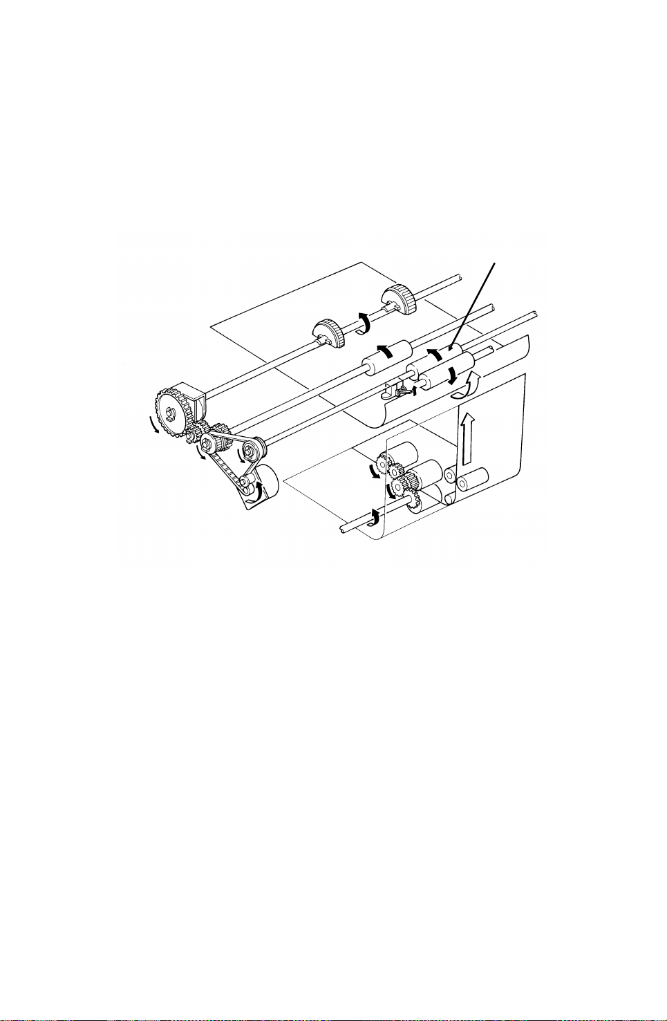
Pick-up and Feed Mechanism
Standard Cassette (Clutch Driven Single Roller Mechanism)
Reference:
Group 3
Facsimile
Manual,
section 4-5-3.
[B]
[D]
[G]
[C]
[A]
[E] [F]
The upper paper feed motor [A] drives the pick-up and feed mechanism. The
paper feed clutch [B] transfers drive from this motor to the feed rollers [C].
When the paper feed clutch turns on, a metal plate [D] moves away from
gear [E]. A pin [F] on this plate releases the gear, and the paper feed roller
turns. However, the clutch switches off after only 0.3 s, and a spring forces
the plate back to the starting position. After one revolution, the rib [G] on the
inside of the gear comes against the pin, and the paper feed roller stops.
When the page memory is full, the upper paper feed motor turns on. At the
beginning, it rotates at a slower speed (202.5 pps) to avoid excessive start-up
noise and start-up current peak.
At 0.1 s after the main motor reaches the correct speed, the motor turns at a
higher speed (405 pps). This higher speed, used for pick-up and feed, ensures that time is not wasted getting paper into the printer. At the same time,
the upper paper feed clutch turns on and paper is fed into the printer.
Shortly after the registration sensor turns on, the main motor has the leading
edge of the paper, so the upper paper feed motor rotates at 202.5 pps again
to match the feed speed of the main motor.
When the trailing edge of the paper has left the registration sensor, the paper
is no longer affected by the upper paper feed motor. The upper paper feed
motor goes back to 405 pps ready for feeding the next page.
2-14
Page 33

DETAILED SECTION DESCRIPTIONS 3rd May, 1994
PRINTER
Lower Cassette (Clutch Driven Two Roller Mechanism)
Reference:
Group 3
Facsimile
Manual,
section 4-5-3.
[A]
[C]
[D]
[E]
Descriptions
Detailed Section
[B]
The lower paper feed motor [A] drives the lower paper feed mechanism, and
the lower paper feed clutch [B] transfers drive from the motor to the lower
pick-up [C] and feed [D] rollers at the correct time.
When the page memory is full, the lower paper feed motor turns on. At the beginning, it rotates at a slower speed (266 pps) to avoid excessive start-up
noise and start-up current peak. After 0.1 s, the motor rotates at a higher
speed (800 pps). This higher speed of rotation, used during pick-up and feed,
ensures that little time is wasted in getting paper out of the cassette and into
the printer.
When main motor lock is achieved, the lower paper feed clutch turns on and
paper is fed into the printer. Shortly after the paper feed sensor [E] is activated, the clutch turns off.
After registration, the upper paper feed and main motors turn on to drive the
registration rollers and feed the paper into the printer. However, rollers driven
by the lower paper feed motor still hold the trailing edge of the paper. So the
lower paper feed motor rotates at 266 pps to match the feed speed of the upper feed and main motors.
When the trailing edge of the paper has left the paper feed sensor, the paper
is no longer affected by the lower paper feed motor. The lower paper feed motor goes back to 800 pps ready for feeding the next page.
2-15
Page 34

[B]
3rd May, 1994 DETAILED SECTION DESCRIPTIONS
PRINTER
Separation Mechanism
Standard Cassette
The standard cassette uses a semicircular roller and corner separator
method of separation.
Lower Cassette
This cassette uses a feed and reverse roller mechanism.
Reference: Group 3 Facsimile Manual (section 4-5-4).
Registration
[C]
[D]
Reference:
Group 3
Facsimile
Manual,
section 4-5-5.
[A]
[E]
Standard Cassette
There is no registration. This is because the upper paper feed motor [A]
drives the registration roller [B] and the upper paper feed rollers [C], and
there is no registration clutch. This means that the registration roller and the
paper feed rollers stop at exactly the same time.
Just after the paper’s leading edge reaches the registration sensor [D], the
upper paper feed motor stops briefly.
Lower Cassette
The upper paper feed motor is off when the leading edge of the paper acti-
vates the registration sensor. The lower paper feed roller [E] continues to
feed the paper for a short while after this, so registration is done in the normal
manner (see section 4-5-5 of the Group 3 Facsimile Manual).
2-16
Page 35

[A]
DETAILED SECTION DESCRIPTIONS 3rd May, 1994
PRINTER
Jam Detection
The machine detects a jam if one of the following conditions exists.
•
The registration sensor or copy feed-out sensor is activated while the
machine is in standby mode.
• The registration sensor still detects paper 9.0 s after the paper feed
clutch turned on.
•
The copy feed-out sensor still does not detect paper 9.0 s after the paper feed clutch turned on.
• The copy feed-out sensor still detects the presence of paper 9.0 s after
it first detected the latest sheet of paper.
• Standard Cassette Only: The registration sensor does not turn on within
2.0 s after the upper paper feed clutch turned on.
• Lower Cassette Only: The lower paper feed sensor does not turn on
within 1.2 s after the lower paper feed clutch turned on.
There is no error detection during paper lift.
Descriptions
Detailed Section
Paper Size Detection
Reference:
Group 3
Facsimile
Manual,
section 4-5-9.
[B]
For both cassettes, the paper size actuator [A] is on the front of the cassette.
The paper size sensor [B] is a row of microswitches. The above diagram
shows the upper paper size sensor.
The cpu disables paper feed from a cassette if the paper size cannot be detected. If the paper size actuator is missing or broken, or if there is no cassette in the cavity, the Add Paper indicator will light.
2-17
Page 36

Lower Cassette
3rd May, 1994 DETAILED SECTION DESCRIPTIONS
PRINTER
Paper End Detection
Upper Cassette
[A]
[B]
Reference: Group 3 Facsimile Manual, section 4-5-8.
[A]
[B]
In both cassettes, the paper end sensor actuator [A] falls through a slot [B] in
the bottom of the tray.
There are no paper height sensors or paper near-end sensors.
Page Separation and Data Reduction
Incoming pages that are similar in length to the copy paper may be reduced
in the sub-scan direction to fit on the paper. Whether or not this happens depends on the settings of bits 1 and 2 of bit switch 02.
Reduction Enabled
If bit 2 of bit switch 02 is at 0, the data will be reduced in the page memory to
fit on the copy paper. However, data will only be reduced if the length of the
incoming page is between 5 mm shorter and a certain maximum length. This
maximum incoming page length that can be reduced depends on the copy paper size and on the reduction ratio stored in RAM addresses 00014F and
000150.
Each paper size can be programmed with a separate reduction ratio. In each
of the two RAM addresses, there is one bit for each possible paper size. The
combination of the bit settings determines the ratio for that paper size.
Bit 7: Not used Bit 5: Legal Bit 3: A4 Bit 1: B5
Bit 6: B4 Bit 4: F4 Bit 2: Letter Bit 0: A5
The ratio is determined in accordance with the following table.
Bit in
00014F
Bit in 000150 0 0 1 1
0: Not used 1: 4/3 0: 8/7 1: 12/11
2-18
Page 37

DETAILED SECTION DESCRIPTIONS 3rd May, 1994
PRINTER
The following table shows the maximum incoming page lengths that can be
reduced for each copy paper size. All lengths are in millimetres. The factory
setting of the reduction ratio is 4/3.
Copy
Paper Type
A5 148 190.7 163.4 156
B5 182 236 202.3 193.1
Letter 279.4 365.9 313.6 299.3
A4 297 389.3 333.7 318.5
F4, F 330.2 433.6 371.7 354.8
Legal 355.6 467.5 400.7 382.5
B4 364 478.7 410 391.6
Copy Paper
Length
Maximum reducible incoming page lengths
Ratio = 4/3 Ratio = 8/7 Ratio = 12/11
The values are calculated as follows.
Maximum incoming page length that can be reduced =
(Copy Paper Length - 5) x Reduction Ratio
For example, for A5 with a reduction ratio of 4/3
Max incoming data length = (148 - 5) x 4/3 = 190.7
Incoming pages that are longer than the maximum length will not be reduced,
but will be printed on two pages and treated in accordance with the setting of
bit 1 of bit switch 02. If this bit is 1, the bottom few lines of the page will be repeated at the top of the next page. If this bit is 0, the next page will continue
from where the first page left off.
Descriptions
Detailed Section
Reduction Disabled
If bit 2 of bit switch 02 is at 1, the data will not be reduced. However, if the in-
coming page is up to x mm longer than the copy paper, the excess portion
will not be printed. The value of x can be from 0 to 15 mm. It is determined by
the setting of RAM address 000151 (copy mode: bits 3 to 0, receive mode:
bits 7 to 4; bits 3 and 7 are the most significant bits).
Hex value Value of x
0 0
1 1
and so on until
15 15
2-19
Page 38

3rd May, 1994 DETAILED SECTION DESCRIPTIONS
PRINTER
Messages more than x mm longer than the copy paper will be printed out on
two pages in accordance with the setting of bit 1 of bit switch 02, as explained above.
Paper Size Selection
If there are two cassettes in the machine, the paper size to use is decided in
accordance with a few simple rules.
• If both cassettes contain the same paper size, the lower cassette will be
used.
• If the received page has to be split up and printed on two pages, both
pages will be the same size.
• If the cassettes contain different sizes, the paper size chosen for print-
ing the received fax message is selected in accordance with the following table of priorities. The table assumes that reduction is enabled and
that the reduction ratio is 4/3.
Paper Size
A5 Letter A4 F, F4 Legal B4
Recv’d
Fax
Message
Size
A5 1 2 3 4 5 6
Letter 6(SR) 1 2 3 4 5
A4 6(SR) 2(R) 1 3 4 5
F, F4 6(SR) 5(R) 4(R) 1 2 3
Legal 6(SR) 5(R) 4(R) 3(R) 1 2
B4 6(SR) 5(R) 4(R) 3(R) 2(R) 1
•
1 is top priority.
•
S: The data has to be separated and printed on more than one page.
• R: The data is reduced to fit on the printer paper.
• If Specified Cassette Selection has been switched on, messages from
specified senders will always go to the upper cassette, regardless of the
paper size or message size.
•
Some of the reports can be printed on A5 paper without page separation. However, if only A5 paper is in the cassettes, reports that need
larger paper sizes will require page separation.
2-20
Page 39

DETAILED SECTION DESCRIPTIONS 3rd May, 1994
PRINTER
6. Transfer Corona Unit
[B]
[A]
Descriptions
Detailed Section
The voltage of the transfer corona unit [A] is between 3.8 and 5.5 kV. It gives
a 200 V charge to the paper to pull the negative toner off the master belt. The
bend [B] in the master belt also helps the paper to leave the belt. There is no
antistatic brush to aid separation.
Reference: Group 3 Facsimile Manual, section 4-6
2-21
Page 40

3rd May, 1994 DETAILED SECTION DESCRIPTIONS
PRINTER
7. Fusing Unit
Fusing Unit Drive
[A]
The main motor [A] drives the fusing unit through a train of gears.
Fusing Unit Control
• Standby temperature: 80 °C
• Printing start temperature: 150 °C
• Maximum printing temperature: 170 °C (monitored by a comparator)
• Thermistor maximum: 280 °C
• Thermostat maximum: 400 °C
When the main power is switched on, the fusing lamp heats up to 80 °C in
about 10 s.
When a ringing signal is detected (or when the user presses Start or Copy for
taking a copy), the fusing lamp heats up to 150 °C in about 15 s.
At the end of printing, the ozone fan stays on until the fusing unit temperature
has fallen below 150 °C.
Reference: Group 3 Facsimile Manual, section 4-7
2-22
Page 41

[C]
DETAILED SECTION DESCRIPTIONS 3rd May, 1994
PRINTER
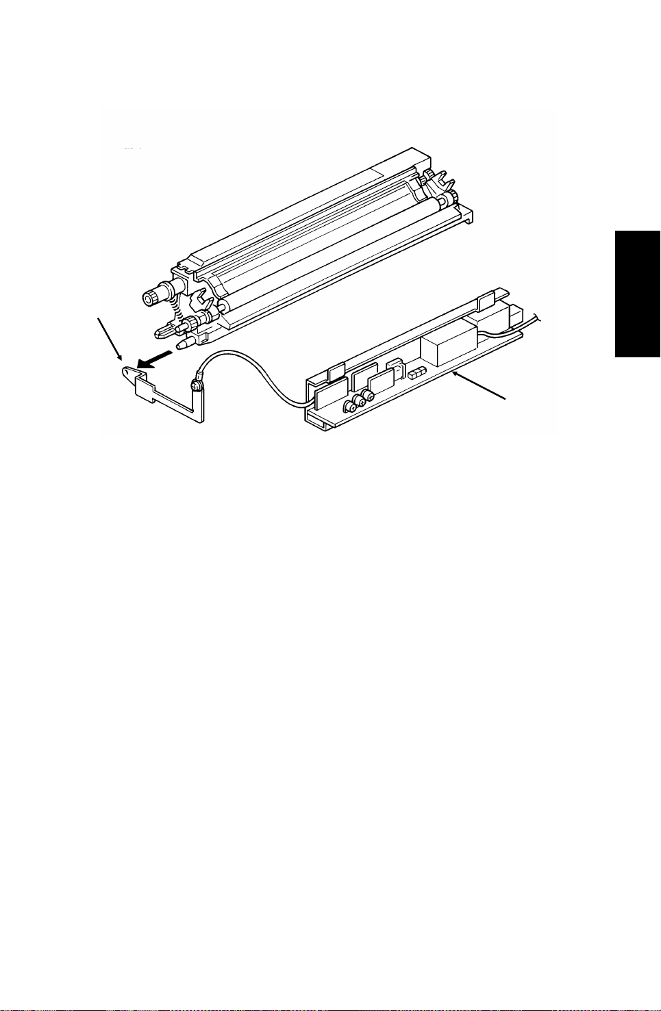
8. Cleaning
[E]
[F]
[E]
[A]
[B]
[D]
[A]
The CTM contains the cleaning unit and the used toner tank.
When the CTM is out of the machine, the shutter [A] is forced against the
cleaning blade [B], which prevents used toner from falling out.
When the CTM is placed inside the machine, a tab on the copy exit cover
pushes plate [C], which moves the shutter away from the cleaning blade to allow toner to be removed from the master belt [D].
The cleaning blade wipes toner off the master belt as it passes the cleaning
unit. The toner goes to the used toner tank. The magnet roller [E] driven by
the main motor catches the toner and the toner is conveyed toward the felt
pad [F]. The felt pad removes the toner from the magnet roller, and the toner
remains in the used toner tank.
There is no toner overflow detection mechanism. This is because the used
toner tank is removed with the old CTM when the toner cassette is empty; the
toner near-end sensor detects this.
Descriptions
Detailed Section
Reference: Group 3 Facsimile Manual, section 4-9
2-23
Page 42

3rd May, 1994 DETAILED SECTION DESCRIPTIONS
PRINTER
9. Quenching
[A]
[B]
The quenching lamp [A] is an LED array. After quenching, the charge on the
master [B] is about -20 V.
Reference: Group 3 Facsimile Manual, section 4-10
2-24
Page 43

DETAILED SECTION DESCRIPTIONS 3rd May, 1994
PRINTER
2.2.2. Circuits
1. Laser Diode
Laser Diode Drive
Front Cover
Interlock Switch
AC/DC
Converter
+24V
1-1
Front Cover
Microswitch
PSU
1-2
2-12
2-3
FCU
+5V
1-1
+24VD
1-10
Descriptions
Detailed Section
+5V
3-1
+5VLD
3-3
4-1
1-8
LDDR
Laser
Diode
Controller
Laser Diode
The laser diode is powered by a special +5V supply, called +5VLD.
There are two switches activated by the front cover; the front cover interlock
switch, and the front cover microswitch. If either of these switches is open,
the power supply to the laser diode is interrupted.
The laser diode is not started until the following conditions have been met:
The main and hexagonal mirror motors are rotating at the correct speeds
•
•
The page memory contains a complete page
• The fusing lamp is at the printing temperature
2-25
Page 44

3rd May, 1994 DETAILED SECTION DESCRIPTIONS
PRINTER
Laser Diode Power Control
Laser
Power
Controller
1-2 1-4 1-5
DATA
Laser
Interface
Laser
Diode
LDDR
1-6
CONTROL FEEDBACKDISABLE
4-44-54-7
4-3
FCU
I/O
Port
CPU
The Laser Interface sends a constant signal to the laser diode on CN4-7, forcing the diode to stay on. The feedback signal returns to the FCU on CN4-3. If
necessary, the cpu adjusts the laser diode power to the correct value by altering the control signal (CN4-4).
If the cpu determines that laser diode power control has failed, it sends CN45 to low, which disables the laser diode.
Service Note
If one of the following occurs, the printer will be disabled, and an Auto Service
Call will be sent to the service station (the message will be LD POWER CONTROL FAILURE).
If there is no response to laser power control (the cpu sends CN4-5 low).
•
•
If the laser diode power supply (+5VLD) is cut.
2-26
Page 45

DETAILED SECTION DESCRIPTIONS 3rd May, 1994
PRINTER
2. Fusing Unit
FUSING UNIT
Fusing
Lamp
Thermistor
30-2
+5V
30-1
LIVE
NEUTRAL
170 C [A]
3-1,4
3-3,6
30-3
I/O
Port
PSU
AC Switching
Circuit
2-6
30-4
2-7
1-7
Main
Power
Supply
Descriptions
Detailed Section
1-6
FCU
The circuit shown in the above diagram controls the fusing unit.
•
The I/O Port monitors the fusing unit temperature at CN30-1.
• The signal from the comparator [A] remains high if the fusing unit tem-
perature is below 170 °C.
• The I/O Port switches the fusing unit on/off using the signal on CN1-7.
•
If the thermistor is accidentally disconnected, the link between CN30-3
and CN30-4 will also be broken. When the cpu detects this, an Auto
Service Call will be sent.
Standby mode
• If the fusing lamp is below 80 °C, the I/O Port makes CN1-7 go high.
This switches on the fusing lamp.
• If the fusing lamp goes above 80 °C, CN1-7 goes low, which switches
off the fusing lamp.
Continued on the next page
2-27
Page 46

3rd May, 1994 DETAILED SECTION DESCRIPTIONS
PRINTER
Printing
• When a ringing signal is detected, CN1-7 goes high, to switch on the
fusing lamp. Also, the ozone fan switches on.
• During printing, the temperature is kept at 170 °C. If the temperature
rises above 170 °C, the output from the comparator changes state. This
causes CN1-7 to go low, which switches off the fusing lamp.
•
If the comparator fails, there are additional safety cutoffs at 280 °C (thermistor) and at 400 °C (thermostat).
After printing
• When the fusing lamp temperature falls back below 130 °C, the ozone
fan switches off.
Service Note
When one of the following error conditions occurs, the I/O Port switches off
the fusing lamp by raising CN1-6 to high. The printer will be disabled, and an
Auto Service Call will be sent to the service station (the message will be HOT
ROLLER DOWN). Details concerning these errors are given in section 6-3
(Service Call Conditions).
Standby mode
• If the fusing lamp takes more than 40 s to reach 80 °C.
• If the fusing lamp is accidentally disconnected for more than 15 s.
During printing
•
If the fusing lamp takes more than 30 s to rise to 150 °C from 80 °C.
•
If the fusing lamp stays below 150°C for more than 10 s.
•
If the thermistor is accidentally disconnected (see the previous page for
details).
After printing
•
If the fusing lamp takes more than 10 minutes to fall back to less than
150 °C.
At any time
• I f the fusing lamp temperature reaches 280°C.
2-28
Page 47

DETAILED SECTION DESCRIPTIONS 3rd May, 1994
PCBs AND THEIR FUNCTIONS
2.3. PCBs AND THEIR FUNCTIONS
2.3.1. FCU
Xenon Lamp
Stamp
Ozon Fan
Eraser
Electrical Clutch
Optional
Counter
PMU
CIG4
Page
memory
MBU
IC
Card
Back-up
(SAF)
OP-
PORT
Driver
Motors
MFPD
Thermistor
Comparator
(THRM)
Descriptions
Detailed Section
PIF
DRAM
FCU
or
or
FONT
ROM
RS232C
MFCP50
(FCP, LIF, QPCR)
DATA ADDRESS BUS
LDAMP
LDDUTY
LDDR
SAF
Comparator
(LDS)
Laser
Diode
VPP50
Sensor
Video
Processing
SBU
CCD
PWM
Circuit
Monitor
Speaker
MIOP
Analog Part
R144
EFXL
PFU
DTMF
Receiver
Analog
Circuit
NCU
Handset
40MBHDD
HDIF
2-29
Page 48

3rd May, 1994 DETAILED SECTION DESCRIPTIONS
PCBs AND THEIR FUNCTIONS
1. CPU (MFCP50)
System clock generation
•
• HDLC framing
•
Interrupt control
• DMA control
• Data compression and reconstruction (high speed MH coding for 1.5 -
second scanning)
•
Real time clock (battery backed-up)
• Memory interface (DRAM, SRAM, ROM, Optional Hard Disk)
• Control of all mechanisms (directly or through other chips)
•
NCU control (through the I/O Port)
• SAF Memory Back-up control
• Ring Detection
2. Laser Interface (LIF)
• DMA control for page memory
• Page memory control
• Laser diode control
• Smoothing
• Printer control
• Printer controller (option) interface
3. QPCR
• Data compression and reconstruction
•
MH/MR/MMR coding
4. I/O Port (MIOP)
• Sensor monitoring (including A/D conversion where necessary)
• Tone detection
• Motor drive (MFPD) control
• Operation panel control
•
Laser Interface control
5. Modem (Rockwell R144EFXL)
• CCITT Group 3 communication (V21, V33, V17, V29, V27 ter)
• HDLC framing
Equalization
•
•
Tone Detection
6. Video Processor (VPP50)
Analog/digital video signal processing
•
7. Analog Circuit
• Analog process of Tx/Rx signals
• Binary process for tone detection
2-30
Page 49

DETAILED SECTION DESCRIPTIONS 3rd May, 1994
PCBs AND THEIR FUNCTIONS
• Monitor speaker control
DTMF detection
•
• Circuit for extra Rx equalizer
8. RAM
• 512 kbyte for ECM and system RAM (with battery back-up)
• 1 Mbyte SAF memory (with battery back-up)
•
1 Mbyte page memory
• 48 kbyte image memory for the VPP50
• 1 Mbyte/2 Mbyte optional memory card (with battery back-up)
•
3 Mbyte optional page memory (PMU)
9. MFPD
• Tx/Rx Motor Control
•
CTM Motor Control
Descriptions
Detailed Section
2-31
Page 50

3rd May, 1994 DETAILED SECTION DESCRIPTIONS
PCBs AND THEIR FUNCTIONS
2.3.2. MBU
System
ROM
DATA AND ADDRESS BUS
Memory Back-up
Control
+
To/From
FCU
1. System ROM (4 Mbit and 2 Mbit EPROM)
•
Contains the software to run the machine
MBU
System
RAM
To/From
FCU
2. System RAM
• 1 Mbit SRAM for parameter storage, line buffer, FIFO, SAF memory ad-
ministration
The SRAM is backed up by the battery on the MBU.
2-32
Page 51

DETAILED SECTION DESCRIPTIONS 3rd May, 1994
PCBs AND THEIR FUNCTIONS
2.3.3. SBU
Analog Video
To the FCU
Drive Clocks
From the FCU
Drivers
CCD
+12V
+12V
+
Emitter
Follower
Descriptions
Detailed Section
Inverter
Amplifier
SBU
2.3.4. OPU
LCD Panel
LCD Panel
Controllers
Operation Panel
Keys
Operation Panel
Operation Panel
Controller
Serial Interface
To/From FCU
LEDs
Output
from the
Scanner
Sensors
2-33
Page 52

3rd May, 1994 DETAILED SECTION DESCRIPTIONS
PCBs AND THEIR FUNCTIONS
2.3.5. LDDR
DATA
2.3.6. PFU(Option)
Lower Cassette
Sensors
Laser
Power
Controller
CONTROL
To/From FCU
PFU
POWER
Indicator
Panel
Lower Cassette
Controller
Driver
Laser
Diode
LDDR
Lower Cassette
Mechanical
Components
Serial Interface
To/From FCU
2-34
Page 53

DETAILED SECTION DESCRIPTIONS 3rd May, 1994
PCBs AND THEIR FUNCTIONS
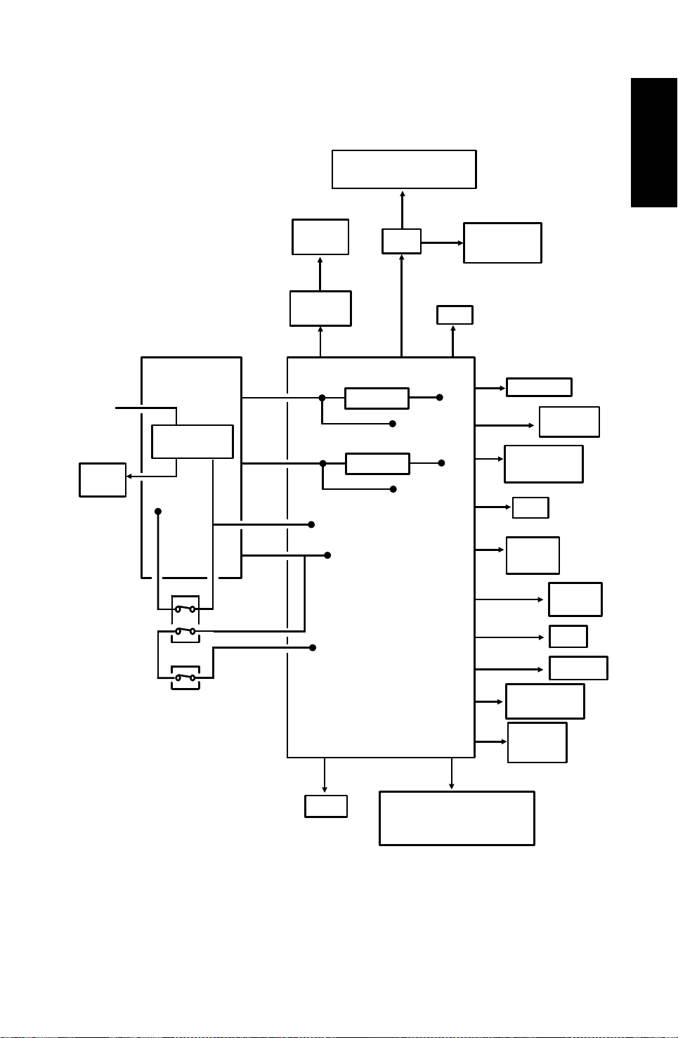
2.3.7. NCU
TIP
RING
T1
R1
To
Network
To
Handset
Protection
Circuit
FG
Line
Current
Detector
Oh
Relay
Di Switch
Ringing
Signal
Detector
Tx/Rx Data
To/From FCU
Descriptions
Detailed Section
To FCU
+24V
Off-Hook
Detector
From FCU
To FCU
NCU
• For simplification, relay drive signals and detector outputs to/from the
FCU are not shown on this diagram.
• In the above diagram, the relays are shown in the standby position for
Auto Receive (Fax) Mode.
2-35
Page 54

3rd May, 1994 DETAILED SECTION DESCRIPTIONS
PCBs AND THEIR FUNCTIONS
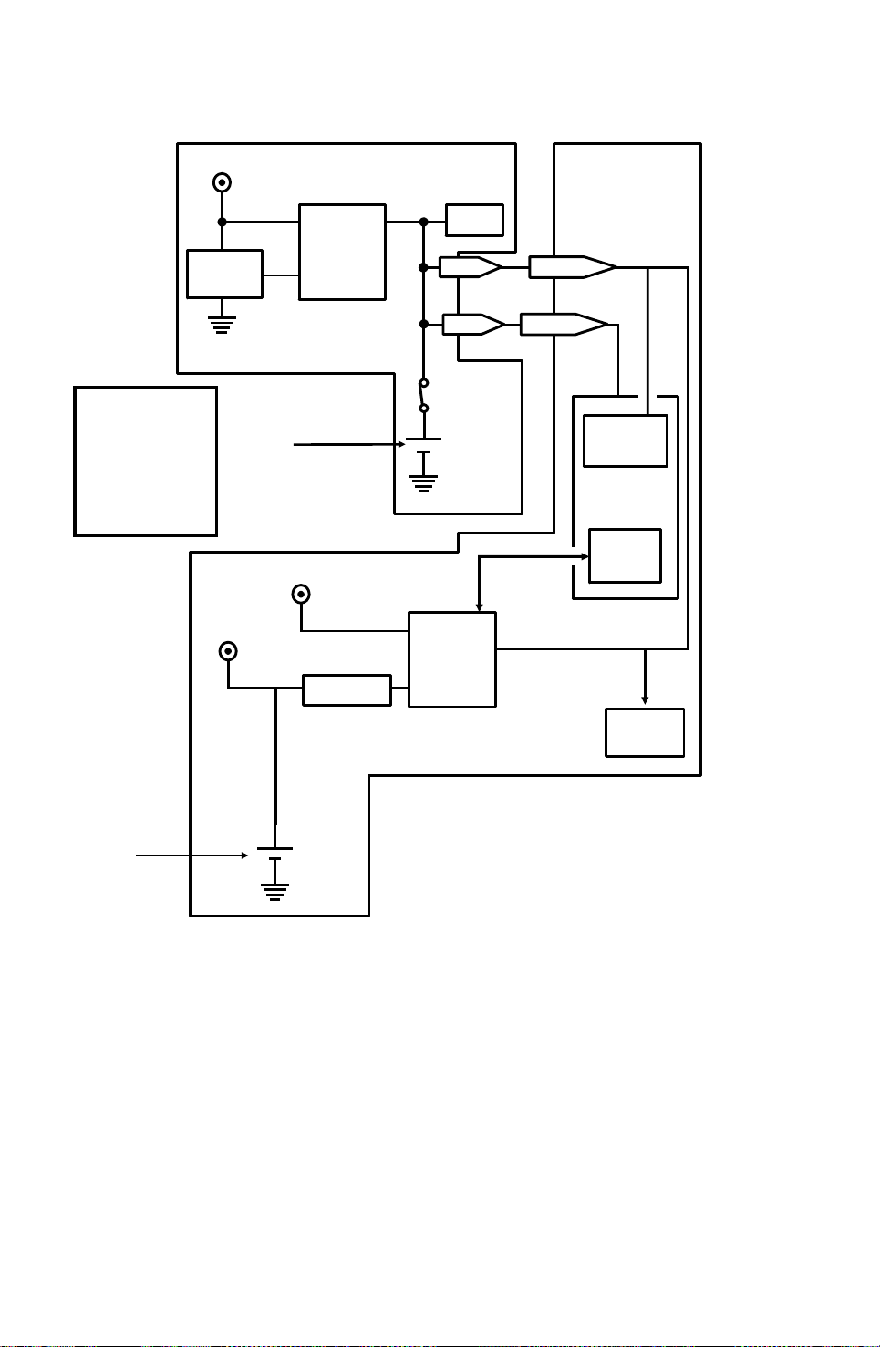
2.3.8. PSU
LIVE
NEUTRAL
GROUND
AC Power
to the
Fusing Lamp
Prevention
Arrestor
Fusing Lamp
Enable
From FCU
Surge
+24VD
AC Switching
Circuit
To
FCU
Main
Switch
+24VD
From
Front Cover
Interlock
Switch
Noise
Filter
+24V
To
Front Cover
Interlock
Switch
Surge Current
Prevention
+24V
To
FCU
Power Supply
Generation
Circuits
+5V
To
FCU
PSU
-12V
To
FCU
Overheat Protection in the PSU
If the PSU thermistor temperature exceeds about 100 °C, the power supply
outputs from the PSU are disabled.
If this happens:
1. Switch off the machine.
2. Take out the PSU and examine it for damage. Take care because it may
be hot.
3. Put back the PSU and switch the machine on. If the machine does not operate, change the PSU.
2-36
Page 55

DETAILED SECTION DESCRIPTIONS 3rd May, 1994
PCBs AND THEIR FUNCTIONS
2.3.9. OPHDIF (Option Hard Disk Interface)
40MHDD
DC-DC
+5V
BUF
Convertor
Address
Decoder
HDIF
Connector
SCSI
Controller
ADDRESS DATA BUS
ADDRESS DATA BUS
MUX
FCU
2.3.10. OPIF (Option Printer Interface)
Address
Decoder
BUF
Serial
I/F
OPHDIF
DIU
Connector
PIF
Connector
HDIF
Descriptions
Detailed Section
RS232C
I/F
DIU
Printer
I/F
ADDRESS DATA BUS
FCU
ADDRESS DATA BUS
I/O
Port
2-37
OPIF
DIU
Connector
PIF
RS232C
I/F
DIU
Page 56

[D]
3rd May, 1994 INSTALLATION
INSTALLING THE MACHINE
3. INSTALLATION
3.1. INSTALLING THE MACHINE
NOTES: Before doing the installation procedure,
1. Read the General Precautions section at the beginning of the
Operator’s Manual.
2. Check the accessories in the accessories box.
- Accessories -
• Document Table • Copy Tray • Document Tray • Handset Holder
• Power Cord • Telephone Line • Screws • Documentation
(You may find some other items in the accessories box.)
- Installation Procedure -
1. Tear off several tapes from the machine, and remove the protective sheet
and tabs from the ADF (Auto Document Feeder). Make sure that no tape
is left inside the machine, especially inside the ADF.
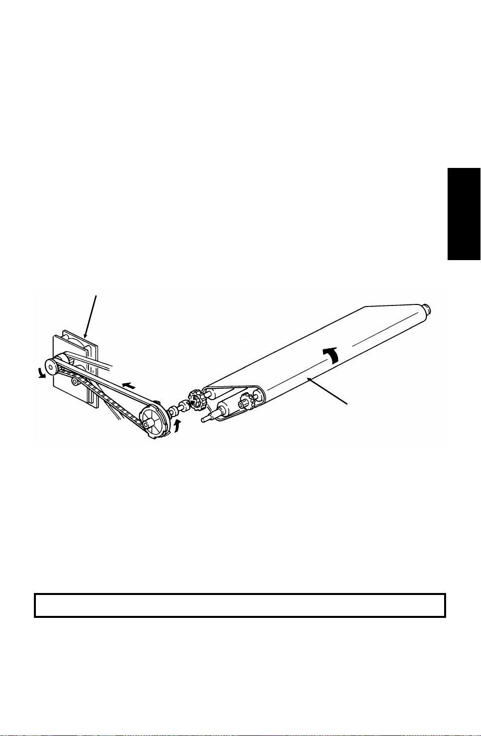
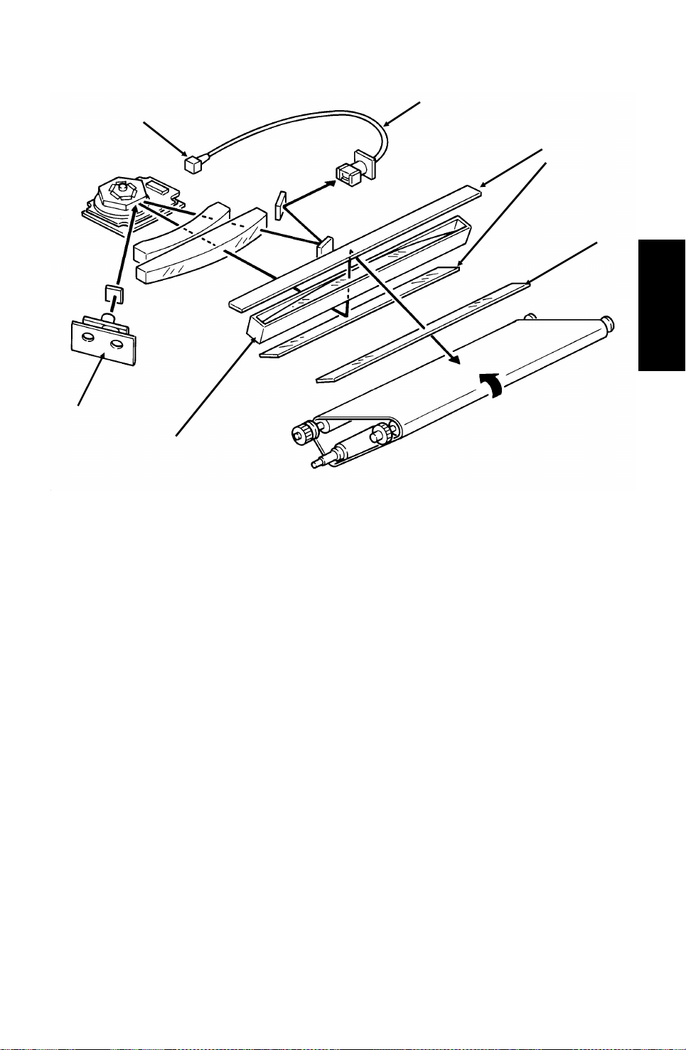
2. Set up the master unit.
2-1. Make sure that the power cord
is not plugged in.
2-2. Remove the master belt
drive cover [A] (1 screw).
2-3. Loosen the joint stopper [B]
(1 screw).
2-4. Pull out the master belt drive
pulley [C] while holding
down the belt tightener [D].
[A]
[B]
[C]
3-1
Page 57

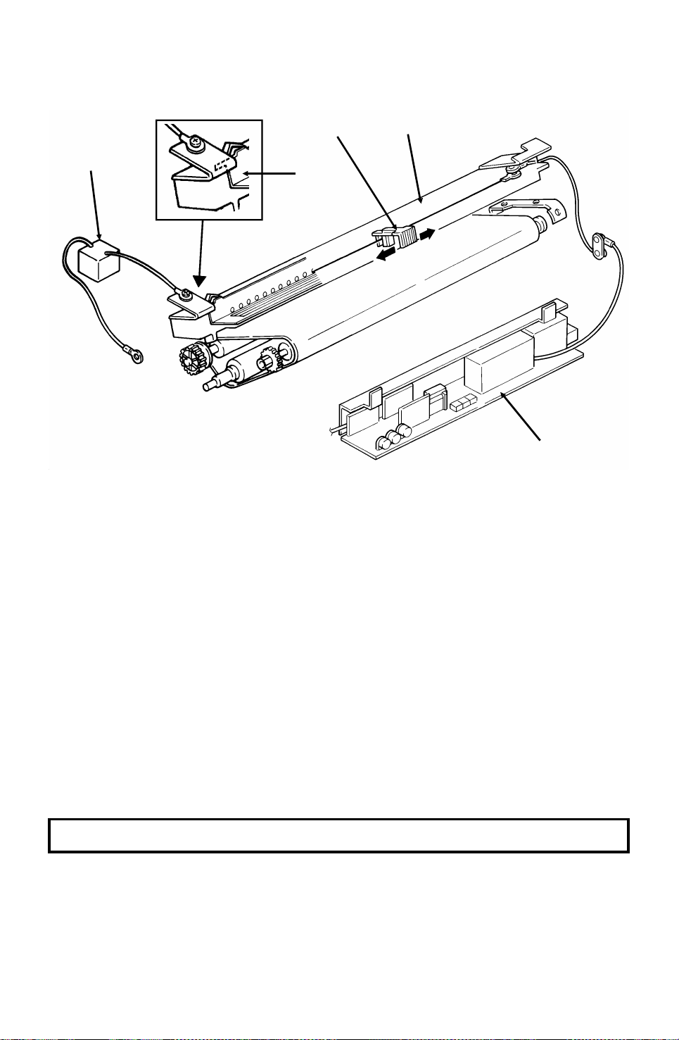
[I]
INSTALLATION 3rd May, 1994
INSTALLING THE MACHINE
2-5. Take your hand away from the
belt tightener [E] first, then carefully let go of the pulley [F].
[E]
[F]
2-6. Open the front cover [G].
2-7. Pull out the plastic tabs [H] at
both sides of the master unit.
Make sure that you do not
leave the red plastic tabs inside the machine.
2-8. Pull out the protective sheet [I],
while raising the master unit
slightly.
Be careful not to touch the
green OPC belt.
2-9. Close the front cover.
2-10. Slide down the belt tightener [J]
for a moment.
The master belt drive pulley [K]
will go back to the normal posi-
tion automatically.
Note: Check that the pulley is
put in the master belt gear prop-
erly.
If not, rotate the pulley slightly,
and try again.
[J]
[H]
[G]
Installation
[K]
2-11. Fix the joint stopper [L]
(1 screw).
2-12. Replace the master belt drive
cover [M] (1 screw).
3-2
[M]
[L]
Page 58

115±20V, 60±1Hz
Grounded
3rd May, 1994 INSTALLATION
INSTALLING THE MACHINE
3. Preparing Paper Cassette
3-1. Slide out the cassette.
Then remove the green
tab [N], while holding
both side of it. Put back
[N]
the cassette.
4. Install the consumable supplies (paper and toner cassette). Refer to your
operator’s manual for full details.If necessary, change the paper size of
the cassette before loading the paper.
5. Attach the document tray [R], copy tray [S], and document table [T] in the
appropriate position.
[R]
[T]
[S]
6. Connect the telephone line and power cord.
If the style of the telephone line is different from the wall socket, contact a
telephone company.
7. Turn on the power switch.
After you finish the installation, some initial programming must be done before you can use
the machine. Refer to your operator’s manual for details.
3-3
Page 59

[A]: 1 screw
[B]
INSTALLATION 3rd May, 1994
INSTALLING ADDITIONAL UNITS
3.2. INSTALLING ADDITIONAL UNITS
3.2.1. Lower Cassette
Check whether there are any messages in the memory. If there are, you
must install the lower cassette and turn the power back on within an hour.
[A]
[B]
Installation
[C]
[C]
Fit pegs [B] into holes [C].
[D]
[D]: 5 screws
3-4
Page 60

[F]
[G]
[H]
3rd May, 1994 INSTALLATION
INSTALLING ADDITIONAL UNITS
[F]
[E]
[E]: 2 connectors
Remove two screws [F].
[G]
Install brackets [G] (2 screws each).
[I]
3-5
Page 61

INSTALLATION 3rd May, 1994
INSTALLING ADDITIONAL UNITS
[J]
Adjust the cassette in accordance
with customer requirements.
Installation
3-6
Page 62

Paper
Feed
Units
3rd May, 1994 INSTALLATION
INSTALLING ADDITIONAL UNITS
Up to 4 of these paper feed units can be added to the machine. However, if
two or more paper feed units are installed, you have to install drawer and
cabinet options in one of the following ways.
Drawers
Cabinet
2 Paper
Feed Units
Machine
3 Paper
Feed Units
4 Paper
Feed Units
3-7
Page 63

INSTALLATION 3rd May, 1994
INSTALLING ADDITIONAL UNITS
3.2.2. Memory Card
• Turn off the power before installing or removing a memory card.
• Make sure that 100% is displayed on the operation panel before install-
ing or removing a memory card, or data will be lost.
Without Printer Interface
With Printer Interface
Installation
3-8
Page 64

3rd May, 1994 INSTALLATION
INSTALLING ADDITIONAL UNITS
3.2.3. Cassette (250 Sheets)
3-9
Page 65

INSTALLATION 3rd May, 1994
INSTALLING ADDITIONAL UNITS
3.2.4. Cassette (500 Sheets)
Installation
3-10
Page 66

[B]: 2 screws
3rd May, 1994 INSTALLATION
INSTALLING ADDITIONAL UNITS
3.2.5. Handset
[A]
[A]: 2 screws
[B]
Connect the modular cord to
either of the telephone socket
at the left side of the machine
marked "TEL 1" and "TEL 2".
3-11
Page 67

INSTALLATION 3rd May, 1994
INSTALLING ADDITIONAL UNITS
3.2.6. Hard Disk
If the ISDN option is installed at the same time, the hard disk option
must be installed prior to the ISDN option.
The installation has three phases.
• SAF Memory initialization
• Bit Switch programming
• Installation procedure
SAF Memory Initialization
1.
Function 6 0 1 9 9 1 , then immediately Yes
2. 0 1
3. Set bit 2 of bit switch 00 to 1.
Yes Function
4.
Bit Switch Programming
1.
Function 6 0 1 9 9 1 , then immediately Yes
2. 0 1
3. Set bit 0 of bit switch 0D to 1.
Yes Function
4.
Make sure that the remaining memory indicator changes to "0%".
Installation
3-12
Page 68

3rd May, 1994 INSTALLATION
INSTALLING ADDITIONAL UNITS
Installation Procedure
1. Turn off the power switch, and unplug the machine from the wall socket.
Caution: Do not plug in or switch on until everything is connected up.
2. Remove the rear cover [A], and disconnect the monitor speaker harness
[B].
3. Take off the right cover [C].
[B]
[C]
[A]
4. Attach the ground plate [D] to the
PSU.
5. Disconnect the connector CN9 [E] from the FCU, and thread the harness
through the hole in the I/F board [F].
6. Plug the I/F board into CN10 [G] on the FCU, and reconnect the harness
to CN9.
[F]
[D]
[G]
[E]
3-13
Page 69

[J]
INSTALLATION 3rd May, 1994
INSTALLING ADDITIONAL UNITS
7. Change the position of the jumper
switch on the hard disk interface
board [H] to turn on the battery
switch.
8. Connect the flat cable [ I ] to the
I/F board and the hard disk unit [J].
Note: Connect putting the " ▼ "
marks together.
9. Attach the hard disk unit .
Note: Tighten the screws [K] that
attach the hard disk unit to the
ground plate [L] and the I/F board
holder [M] together.
10. Remove the option cover [N] from
the rear cover.
[L]
[M]
[I]
[H]
[K]
11. Reconnect the monitor speaker
harness, and put back the rear
[O]
cover and right cover.
12. Attach the hard disk cover [O].
13. Plug in the machine, then turn on
the power.
[N]
14. Enter the service mode and format
the hard disk (function 17).
Caution: Do not turn off the switch until formatting is completed.
Formatting the hard disk atting takes about 10 minutes.
15. Turn off the power, then turn on the power after a few seconds.
16. Print the system parameter list and make sure that the Total Memory Size
indicates “HD”.
17. Go to the standby mode and make sure that the remaining memory
indicator shows “100%”.
Installation
3-14
Page 70

[C]
[F]
3rd May, 1994 INSTALLATION
INSTALLING ADDITIONAL UNITS
3.2.7. Optional 400 dpi Page Memory (PMU)
If other options are installed at the same time, install the 400 dpi board
first.
1. First, print any messages still stored in the SAF.
2. Turn off the power switch, and unplug the machine from the wall socket.
Caution: Do not plug in or switch on again until
everything is connected up.
3. Remove the rear cover [A], and dis-
connect the monitor speaker harness [B].
[A]
4. If a memory card [C] is installed on
the FCU, remove it.
5. Take off two screws [D] that are
holding the FCU board.
6. Disconnect all harnesses from the
FCU except CN34 and CN35 that
are connected to the NCU.
7. Slide out the FCU.
8. Plug the 400 dpi board [E] into
connector CN14 [F] on the FCU.
9. Put back the FCU, and reconnect
the harnesses.
10. Tighten the screws [D], and install
the memory card if necessary.
11. Reconnect the monitor speaker har-
ness and put back the rear cover.
12. Plug in the machine, then turn on
the power.
[B]
[D]
[E]
3-15
Page 71

INSTALLATION 3rd May, 1994
INSTALLING ADDITIONAL UNITS
3.2.8. ISDN OPTION
• If other options are installed at the same time, install them before
doing the ISDN option.
• It is not possible to install both the Printer Interface and the ISDN
option on the same machine.
1. First, any messages still stored in the SAF.
2. Turn off the power switch, and unplug the machine from the wall socket.
Caution: Do not plug in or switch on again until everything is connected
up.
3. Remove the rear cover [A], and disconnect the monitor speaker harness
[B].
4. Remove the left cover [C] and the NCU [D].
5. Remove the MBU holder [E].
[A]
[B]
[D]
Installation
[C]
[E]
3-16
Page 72

3rd May, 1994 INSTALLATION
INSTALLING ADDITIONAL UNITS
6. Install the ground plate [F] and the bracket [G].
7. Plug the CIG4 board [H] into CN 11 on the FCU, then tighten the screws
that secure it to the bracket.
8. Remove the blind cover [I] from the rear cover, and install the jack cover
[J] instead.
9. Reconnect the monitor speaker harness and put back the rear cover.
10. Connect the ISDN cable to the machine.
11. Plug in the machine, then turn on the power.
12. Program the G4 parameter switches, internal switches, and ISDN service
modes as explained in the service manual.
13. Check whether G4 can be selected or not from the operation panel.
[H]
[F]
[J]
[G]
[ I ]
3-17
Page 73

[E]
[C]
INSTALLATION 3rd May, 1994
INSTALLING ADDITIONAL UNITS
3.2.9. PRINTER INTERFACE
Notes:
1. Before you start installing the printer interface option, prepare
the"PRINTER I/F INSTALLATION SET TYPE 90" in advance.
2. It is not possible to install both the Printer Interface and the ISDN option on the same machine.
3. Do not plug in or switch on again until everything is connected up.
- How to install the Printer Interface Unit -
1. First, print any messages still stored in the SAF.
2. Turn off the power switch, and unplug the machine from the wall socket.
3. Slide out the cassette(s).
4. Take off the rear cover [A], and discon-
nect the monitor speaker harness [B].
[A]
5. If a memory card [C] is installed in the
machine, remove it.
Installation
6. Take off the monitor speaker [D] from
the rear cover.
7. Attach the monitor speaker to the
printer interface unit [E].
8. Disconnect the connector CN9 [F] from
the FCU, and thread the harness
through the hole in the I/F board [G].
9. Plug the I/F board into CN10 [H] on
the FCU, and reconnect the harness to
CN9.
10. Attach the bracket [ I ].
Note: Tighten the screws that attach
the bracket to the I/F board
holder [J] together.
Note: This bracket is used only when
an RS232C option is installed.
[G]
[D]
[B]
[F]
[J]
[H]
[I]
3-18
Page 74

[M]
3rd May, 1994 INSTALLATION
INSTALLING ADDITIONAL UNITS
11. Connect the flat cable [K] to the
printer interface unit [L].
Note: Connect it putting the " ▼ "
marks together.
[K]
[L]
12. Reconnect the monitor speaker har-
ness [M].
[N]
[O]
13. Hold the printer interface unit [N] near
the machine with one hand, and plug
the flat cable [O] from the
Printer I/F Installation Set into the connector on the I/F board.
Note: Do not use the flat cable which
was connected originally.
Note: Connect it putting the " ▼ "
marks together.
14. Attach the printer interface unit [P].
15. Remove the memory option cover [Q].
16. Attach the memory card guide [R].
Then install the memory card if necesssry.
17. Put back the option memory cover.
18. Put back the cassette(s)
19. Plug in the machine, then turn on the
power.
20. Make sure that the On Line indicator
is lit and Function 37 can be accessed from the operation panel.
[P]
[Q]
[R]
3-19
Page 75

[D]
INSTALLATION 3rd May, 1994
INSTALLING ADDITIONAL UNITS
2. How to Install the Memory Expansion Board
1. Print any messages still stored in the SAF.
2. Turn off the power and unplug the machine from the wall socket.
3. Remove the memory option cover [A]
and the memory board cover [B].
[B]
[A]
4. Insert the memory expansion board [C].
5. Put back the memory board cover [D]
and the memory option cover [E].
[E]
6. Plug in the machine, then turn on the power.
Installation
[C]
3-20
Page 76

3rd May, 1994 INSTALLATION
INSTALLING ADDITIONAL UNITS
3.2.10. Optional Counter
1. Turn off the power, and unplug the machine from the
wall socket.
2. Remove the rear cover [A]
(4 screws) and right cover [B]
(6 screws).
3. Attach the counter [C]
(1 screw).
4. Connect the harness [D] to
CN40 on the FCU.
Note: Make sure that the har-
ness is fed through the
machine without getting
entangled around components. See the diagram.
5. Test the counter before reassembling the machine.
5-1. Carefully plug in the
machine, then turn on
the power.
Caution: Do not touch
the PSU.
5-2. Copy a few sheets.
5-3. Check that the counter
increments correctly.
Then turn off the
power, and unplug the
machine.
[C]
[B]
[A]
CN40
[D]
6. Replace the rear and right
covers.
7. Plug in the machine, then turn on the power.
3-21
Page 77

[F]
INSTALLATION 3rd May, 1994
INSTALLING ADDITIONAL UNITS
3.2.11. Master Unit
How to Remove the Old Master Unit
1. Turn off the power switch and unplug the machine from the wall socket.
Caution: Before turning off the power switch, make sure that the remain-
ing memory capacity is 100%. If the machine is switched off for more
than an hour, any fax messages in memory may be lost.
2. Remove the document table and copy tray.
3. Remove the master belt drive cover
[A] (1 screw).
[A]
4. Loosen the joint stopper [B]
(1 screw).
[B]
5. Pull out the master belt drive pulley
[C] while holding down the belt tightener [D].
6. Take your hand away from the belt
tightener [E] first, then carefully let
go of the pulley [F].
7. Open the front cover [G].
[E]
[D]
[C]
Installation
[G]
3-22
Page 78

3rd May, 1994 INSTALLATION
INSTALLING ADDITIONAL UNITS
8. Slide out the toner cassette [H].
Caution: Do not touch [ I ] or [J] be-
cause your hands may get dirty.
[ I ]
[J]
[H]
9. Remove the master unit stopper [K]
(1 screw).
[K]
10. Slide out the old master unit [L].
How to Install the New Master Unit
11. Take out the master belt protection sheet. Then insert the master unit
along the guide rail inside the machine until it is in position.
Caution:Do not touch the belt surface (dark green) and do not expose
it to direct sunlight for a long time.Do
not hold the knob under the master
unit.
[L]
3-23
Page 79

INSTALLATION 3rd May, 1994
INSTALLING ADDITIONAL UNITS
12. Take out the master unit holder [M] by
twisting it upwards.
[M]
13. Install the master unit stopper [N]
(1 screw).
14. Install the toner cassette.
15. Close the front cover.
16. Slide down the belt tightener [O] for a
moment. The master belt drive pulley
[P] will go back to the normal position
automatically.
Note: Check that the pulley is put in
the master belt gear properly. If not, rotate the pulley slightly, and try again.
17. Fix the joint stopper [Q] (1 screw).
18. Replace the master belt drive cover
[R] (1 screw).
19. Replace the document table and copy
tray.
[O]
[R]
[N]
Installation
[P]
[Q]
20. Connect the power cord and turn on
the power.
3-24
Page 80

3rd May, 1994 INSTALLATION
INITIAL PROGRAMMING
3.3. INITIAL PROGRAMMING
Check the following:
•
Is the country code in the NCU parameters (Function 09, parameter 00)
correct for the country of installation? In the USA, it should be 17.
• Do any bit switch or other settings have to be changed to match line
conditions or user requirements?
•
Have you programmed the serial number (Function 15, section 4-1-18)?
The user should program the following items after installation:
•
Telephone Line Type
• RTI, TTI, and CSI
• ID Codes (ID Code, Confidential ID, Memory Lock ID)
•
The fax machine’s own telephone number
• Date and Time
• Language Selection
3-25
Page 81

SERVICE TABLES AND PROCEDURES 3rd May, 1994
SERVICE LEVEL FUNCTIONS
4. SERVICE TABLES AND PROCEDURES
4.1. SERV ICE LEVEL FUNCTIONS
To enter service mode, press the following sequence of keys:
Function 6 0 1 9 9 1
then immediately Yes
SERVICE FUNCTION NO. _
01BIT SW. 02PARA LIST
03ERROR CODE 04SVC MONITOR
4.1.1. Bit Switch Programm ing (Function 01)
1. After entering se rvice mode,
press 0 1
BIT SWITCH
DF: 00000000
SW:00 00000000
Bit 7 is displayed at the left , an d bit 0 at the right. The de fa ult settings are
shown on the top line, and the current settings on the bottom.
2. • Increment bit switch: ↓
• Decrement bit switch: ↑
Example:
Display bit switch 3: ↓ x 3
BIT SWITCH
DF: 00000000
3. Adjust the bit switch.
Example: To change the value of
bit 7, press 7
4. Either:
• Adjust more bit switches - go to step 2.
• Finish - Yes
SW:03 00000000
BIT SWITCH
DF: 00000000
SW:03 10000000
4-1
Page 82

3rd May, 1994 SERVICE TABLES AND PROCEDURES
SERVICE LEVEL FUNCTIONS
4.1.2. System Parameter Lis t (Function 02)
1. After entering se rvice mode,
press 0 2
G3 SYSTEM PARAMETER LIST
PRESS START
2. Start
3. After printing, press Function
Refer to the following table for th e mea nin g of each coun te rs in the list.
Counter Name Meaning
SCN Counter Scanned page counter (sum of fax transmission, copying,
and scanning OMR sheets)
PRT Counter Printed page counter (sum of fax reception, copying,
printing from printer controller, and printing reports)
TX Counter Transmitted page counter
RX Counter Received page counter
PM Counter Printed page counter used for PM auto service call.
(counter value is the same as PRT counter)
PM Default Threshold number of printed pages for PM call. (The
default value is 60,000 pages.)
OPU Counter Master unit counter to indicate how many pages have been
printed with currently installed master unit.
CTM Counter Toner counter to indicate how many pages have been
printed with currently installed toner cartridge.
CPY Counter Copied page counter
CASSETTE 1 Printed page counter for the first paper feed station.
CASSETTE 2 Printed page counter for the second paper feed station.
CASSETTE 3 Printed page counter for the third paper feed station.
CASSETTE 4 Printed page counter for the fourth paper feed station.
CASSETTE 5 Printed page counter for the fifth paper feed station.
PRN Counter PC printer output counter
DOC. JAM ADF jam counter
COPY JAM Jam counter for every printer jam
FEED OUT JAM Jam at fusing exit counter
INT. JAM Jam at registration and relay counter
CST 1 JAM Jam counter for the first paper feed station.
CST 2 JAM Jam counter for the second paper feed station.
CST 3 JAM Jam counter for the third paper feed station.
CST 4 JAM Jam counter for the fourth paper feed station.
CST 5 JAM Jam counter for the fifth paper feed station.
4-2
Page 83

SERVICE TABLES AND PROCEDURES 3rd May, 1994
SERVICE LEVEL FUNCTIONS
4.1.3. Error Code Display (Function 03)
1. After entering se rvice mode,
press 0 3
ERROR CODE
CODE=0-14 JUL 10 3:15PM
2. Either:
• Scroll through the error code s using ↑ and ↓
• Finish - Yes
4.1.4. Service Monitor Report (Function 04)
1. After entering se rvice mode,
press 0 4
SERVICE MONITOR REPORT
PRESS START
2. Start
4.1.5. Protocol Dump (Function 05)
1. After entering se rvice mode,
press 0 5
2. Start
G3 PROTOCOL DUMP LIST
PRESS START
4-3
Page 84

3rd May, 1994 SERVICE TABLES AND PROCEDURES
SERVICE LEVEL FUNCTIONS
4.1.6. RAM Display/Rewrite/ Pr intout (Function 06)
1. After entering se rvice mode,
press 0 6
RAM NO. _
0.MEMORY R/W 1. MEMORY DUMP
2. Either:
• Display or rewrite RAM data: 0
Go to step 3.
MEMORY R/W
ADDRESS= 000000 DATA=FF
• Print a RAM dump list: 1 . Go
to step 6.
3. Input the address that you wish to
see.
Example: 0 0 1 1 2 2
If necessary, use ↑ and ↓ to
increment or decrement the RAM
address.
4. If you wish to change the conte nt s
of the RAM address, press → to
move the cursor to the data side.
Then input the new data.
Example: F F
MEMORY DUMP
ADD. H - ADD. FFH
MEMORY R/W
ADDRESS= 001122 DATA=00
MEMORY R/W
ADDRESS= 001122 DATA= FF
5. Either:
• View more addresses - ← then go to step 3.
• Finish - Yes . Go to step 2.
6. Input the range of addresses that you wish to print.
Example: Addresses 22AA00 to 22B BFF
2 2 A A 2 2 B B Start
4-4
Page 85

SERVICE TABLES AND PROCEDURES 3rd May, 1994
SERVICE LEVEL FUNCTIONS
4.1.7. Checking the Counters (Function 07)
1. After entering se rvice mode,
press 0 7
COUNTER R/W NO. _
0 COUNTER 1 PM COUNTER
2 CTM COUNTER 3 OPU COUNTER
2. Either:
• Check the scanned, printed, transmitted, and received page counters,
and the printer and scanner jam counters: 0 . (To see the jam
counters, press 0 then ↓ . )
• Check the PM counter: 1
• Check the CTM counter: 2
• Check the OPU counter: 3
3. To change the contents of a counter, press → until the required
counter is highlighte d on the scre en, then input the new value.
4.1.8. Clearing the Counters (Function 08)
1. After entering service mode,
press 0 8
COUNTER CLEAR NO. _
0 PM COUNTER 1 CTM COUNTER
2 OPU COUNTER
2. Either:
• Clear the PM counter: 0
• Clear the CTM counter: 1
• Clear the OPU counter: 2
4.1.9. NCU Parameters (Function 09)
1. After entering se rvice mode,
press 0 9
NCU NO. _
0 NCU 1 MODEM/DTMF
2. 0
NCU
NO.00= 019
PRESS YES/NO
4-5
Page 86

3rd May, 1994 SERVICE TABLES AND PROCEDURES
SERVICE LEVEL FUNCTIONS
3. Scroll through the parameters using ↑ and ↓ .
Enter new values at the keypa d where necessary.
Example: Set NCU parameter 04 to 005.
↓ ↓ ↓ ↓ 0 0 5 Yes
4. To go to the next parameter: Yes
5. To finish: No Yes
Note: Parameter 00 is the Country Code, and Parameter 01 is the Tx Level
(Input the value of the Tx level x -1 ; f or e xamp le, if the Tx level should
be -9 dB, input 9).
4.1.10. Modem/DTMF Tone Tests (Function 09)
1. After entering se rvice mode,
press 0 9 then 1
MODEM/DTMF
NO.01=V29 9600 BPS
PRESS START
2. Scroll through the available tests using ↑ and ↓ .
Example: To do an 1100 Hz tone test. ↓ ↓ ↓ Start
To finish a test: Stop
3. To finish: Yes x 2
4.1.11. Operation Panel Tests (Function 10)
1. After entering se rvice mode,
press 1 0
OP.PANEL NO. _
0 LED 1 ALARM
2 RINGER 3 LCD
2. Either:
• Test the LEDs on the operation panel: 0 Start
• Test the alarm tone: 1 Start
• Test the ringer: This test is not used in t his ma chin e.
• Test the LCD: 3 Start
4-6
Page 87

SERVICE TABLES AND PROCEDURES 3rd May, 1994
SERVICE LEVEL FUNCTIONS
3. To finish a test: Stop Yes
4. Either:
• Do another test. Go to step 2.
• To finish: Yes
4.1.12. Scanner Tests (Function 11)
1. After entering se rvice mode,
press 1 1
SCANNER NO. _
0 XE LAMP 1 ADF
2. Either:
• Switch on the xenon lamp: 0 Start
• Test the auto document feeder: Place a sheet of pap er in the document
feeder, then 1 Start
3. To finish a test: Stop
4. To finish: Yes x 2
4.1.13. Printer Tests (Function 12)
1. After entering se rvice mode,
press 1 2
PRINTER NO. _
0 PATTERN 1 MECH TEST
2 FAN MOTOR 3 CTM MOTOR
2. Either:
• Print a test pattern : 0 .
Go to step 3.
• Test the printer mechanism: 1 Start
• Test the fan motor: 2 Start
• Test the CTM motor: Remove the CTM, then press 3 Start
PATTERN NO. _
0 DIAGONAL 1 1 DIAGONAL 2
2 VERTICAL 3 GRAND PRIX
To finish a test: Stop
4-7
Page 88

3rd May, 1994 SERVICE TABLES AND PROCEDURES
SERVICE LEVEL FUNCTIONS
3. Press a key from 0 to 5, depending on the requ ired pattern. Use ↑
and ↓ to see what patterns are available.
4. Start
A test pattern is printed.
5. To finish: Yes x 2
4.1.14. RAM Tests (Function 13)
1. After entering se rvice mode,
press 1 3
RAM TEST NO. _
0 SRAM 1 SAF
2 PAGE MEMORY
2. Either:
• Test the SRAM: 0 Start
• Test the SAF: 1 Start
• Test the page memory: 2 Start
If there is a problem, a display of the following type will occur.
SAF
PRESS START
ADDRESS=300002 W=55 R=00
Keep a note of the information on the display, then press Start to resume
testing.
3. When the test has finishe d, "OK " is displa yed. Press Yes to finish.
4.1.15. Service Station Telephone Number (Function 14)
1. After entering se rvice mode,
press 1 4
S.S.NO ENTER FAX NUMBER
NO
TO CANCEL
4-8
Page 89

SERVICE TABLES AND PROCEDURES 3rd May, 1994
SERVICE LEVEL FUNCTIONS
2. Input the telephone number of th e service station that will receive Auto
Service calls from this machine. The n press Yes .
If the ISDN Option kit has bee n inst alle d, press the Line Selector key to
select either G3 or G4 before in pu tt ing the number.
4.1.16. Serial Number (Function 15)
1. After entering se rvice mode,
press 1 5
SERIAL NO.
2. Enter the machine’s serial no at the keypad.
To correct a mistake: No
3. If the display is correct: Yes
4.1.17. File Transfer (Function 16)
1. After entering se rvice mode,
press 1 6
FILE TRANSFER ENTER FAX NUMBER
NO
TO CANCEL
2. Input the telephone nu mber of the fax machine to which you wish to tra nsfer all the files. Then pre ss Yes Start .
If the ISDN Option kit has bee n inst alle d, press the Line Selector key to
select either G3 or G4 before in pu tt ing the number.
4.1.18. Hard Disk Initialization (Function 17)
1. After entering se rvice mode,
press 1 7
HD NO. _
0.INITIAL 1.FORMAT
2.TEST
2. Either:
• Erase all SAF files from the hard disk: 0 Start
• Format the hard disk: 1 Start
• Test the hard disk: 2 Start
4.1.19. Group 4 Communication Para me ter s (Functi on 18)
This function is described in the service manual for the optio nal I SDN kit.
4-9
Page 90

3rd May, 1994 SERVICE TABLES AND PROCEDURES
BIT SWITCHES
4.2. BIT SWITCHES
WARNING
Do not adjust a bit switch that is described as "Not used", as this
may cause the machine to malfunction or to operate in a manner
that is not accepted by local regulations. Such bits are for use only
in other areas, such as Japan.
If you change some bit switches, you must turn the main switch off and on after
you finish changing the bit switches.
4.2.1. Bit Switch Definitions
Bit Switch 00
FUNCTION COMMENTS
0 MTF process
0: Enabled 1: Disabled
1 RAM reset level 2
1: Reset
2 RAM reset level 3
1: Reset
Note: RAM reset level
1 is a RAM
adjustment. It is not
described in this
manual.
3 Not used Do not change the factory setting.
4 Inclusion of technical
data on the TCR
0: No 1: Yes
0: The MTF process is used when required by the software.
1: The MTF process is never used.
When this bit is set to 1, all items stored in the RAM are
reset except the clock, and then this bit changes back to 0
automatically. Also, all image files in the SAF memory are
erased.
When this bit is set to 1, some items stored in the RAM are
reset, then this bit changes back to 0. All items are reset
except the bit switch and NCU parameter settings, clock,
own tel. no., CSI, RTI, TTI, Quick Dials, Speed Dials,
Groups, and the TCR memory. Also, all image files in the
SAF memory are erased.
This bit switch is recommended for use when it is necessary
to clear the SAF, as fewer RAMs will need reprogramming.
1: Instead of the personal code, the following data are listed
on the TCR (G3 communications only).
e.g., 14.4K A1 01 03 00 02
First number: Final modem rate (for example, 14.4K
means 14,400 bps)
Second and third numbers: These are a measure of the
error rate. The left hand figure is the low byte and the right
hand figure is the high byte. In general, a larger number
means more errors.
Fourth number: Cable equalizer;
00 = Equalizer is Off, 01 = Low, 02 = Medium, 03 = High
Fifth number (Rx mode only): Total number of error lines
that occurred during non-ECM reception.
Sixth number (Rx mode only): Total number of burst error
lines that occurred during non-ECM reception.
These numbers are fixed at 00 for tx mode and ECM
reception.
4-10
Page 91

SERVICE TABLES AND PROCEDURES 3rd May, 1994
BIT SWITCHES
Bit Switch 00
FUNCTION COMMENTS
5 Monitor speaker
during video data
communication (tx
and rx)
0: Disabled
1: Enabled
6 Protocol dump list
output
7 Communication
parameter display
0: Disabled
1: Enabled
Used for testing. Set this bit to 1 to hear the fax data signal
(phase C of CCITT T.30 protocol).
Make sure that you reset this bit after testing.
This is only used for communication troubleshooting. It
shows the content of the transmitted facsimile protocol
signals. Always reset this bit to 0 after finishing testing.
This is a fault-finding aid. The LCD shows the key
parameters (see below). This is normally disabled because
it cancels the CSI display for the user.
Make sure that you reset this bit after testing.
Communication parameter dis pla y
Mode DCS: CCITT G3
NSS: Non-standard G3
Modem rate 144S: 14,400 bps with short training (V.17)
144L: 14,400 bps with long training (V.33)
120S: 12,000 bps with short training (V.17)
120L: 12,000 bps with long training (V.33)
96TS: 9,600 bps using TCM, with short training (V.17)
96TL: 9,600 bps using TCM, with long training (V.33)
72TS: 7,200 bps using TCM, with short training (V.17)
72TL: 7,200 bps using TCM, with long training (V.33)
96: 9600 bps
72: 7200 bps
48: 4800 bps
24: 2400 bps
Communication mode
Compression mode
Resolution SF: G3 Super Fine at 16 x 15.4 dots per mm
ECM: With ECM EFC: Using EFC
SSC: Using SSC NML: With no ECM, SSC, or EFC
MMR: MMR compression
MR: MR compression
MH: MH compression
SFi: G3 Super Fine at 400 x 400 dots per inch
SSF: G3 Fine at 8 x 15.4 dots per mm
SSi: G3 Fine at 200 x 400 dots per inch
DTL: G3 Detail at 8 x 7.7 dots per mm
DTi: G3 Detail at 200 x 200 dots per inch
STD: G3 Standard at 8 x 3.85 dots per mm
STi: G3 Standard at 200 x 100 dots per inch
400x400: G4 Super Fine
200x200: G4 Detail
200x100: G4 Standard
4-11
Continued on the next page
Page 92

3rd May, 1994 SERVICE TABLES AND PROCEDURES
BIT SWITCHES
I/O Rate 0M: 0 ms/line 10M: 10 ms/line
2/M: 2.5 ms/line 20M: 20 ms/line
5M: 5 ms/line 40M: 40 ms/line
Width and
reduction
Bit Switch 01
LCD contrast
0
Bit 2 1 0 Contrast
1
0 0 0 Brightest
0 0 1 ↓
2
↓ ↓
1 1 0 ↓
1 1 1 Darkest
Memory read/write by RDS
Bit 4 3 Setting
3
0 0 Always enabled
0 1 User selectable
4
1 0 User selectable
1 1 Always disabled
5 Dedicated transmission parameter
programming/printing all SAF
files/erasing all SAF files
0: Disabled 1: Enabled
6 Not used Do not change the factory setting.
7 PM call
0: Enabled 1: Disabled
=A4: A4 (8.3"), no reduction
=B4: B4 (10.1"), no reduction
=A3: A3 (11.7"), no reduction
>A4: Reduced to A4 (8.3") before transmission
>B4: Reduced to B4 (10.1") before transmission
FUNCTION COMMENTS
Use these bit switches to adjust the brightness
of the LCD on the operation panel.
(0,0): At any time, an RDS system can read or
write RAM data such as TTI and bit switches.
(0,1), (1,0): Normally, RDS systems are locked
out, but the user can temporarily switch RDS
on to allow an RDS operation to take place.
RDS will automatically switch off again after a
certain time, which is stored in a RAM address
(see section 4-5). Note that, if an RDS
operation takes place, RDS will not switch off
until this time limit has expired.
(1,1): All RDS systems are always locked out.
This bit must be set to 1 before attempting to
program dedicated transmission parameters
(using Function 31 or 32), or printing all files
stored in the SAF memory (using Function 24)
or erasing all files stored in the SAF memory
(using Function 21). After finishing with these
operations, return this bit to 0.
0: The machine will send an Auto Service Call
when the PM interval has expired. This interval
is adjustable by RAM address. The default
setting is every 10,000 copies (based on the
Print counter).
1: The user will do maintenance as explained
in the Operator’s Manual whenever problems
occur.
4-12
Page 93

SERVICE TABLES AND PROCEDURES 3rd May, 1994
BIT SWITCHES
Bit Switch 02
FUNCTION COMMENTS
0 Page separation mark
0: Enabled 1: Disabled
1 Repetition of data when the
received page is longer than the
printer paper
0: Disabled 1: Enabled
2 Reduction of the length of
received data
0: Enabled 1: Disabled
3 Not used Do not change the factory settings.
4
5 Text/photo determination during
scanning in Halftone mode
0: Disabled 1: Enabled
Maximum transmittable document
length
6
Bit 7 6 Setting
0 0 600 mm
7
0 1 1200 mm
1 0 14 m
1 1 100 m
0: If a received page has to be printed out on two
sheets, an "x" inside a small box is printed at the
bottom right hand corner of the first sheet, and a
"2" inside a small box is printed at the top right
hand corner of the second sheet. This helps the
user to identify pages that have been split up.
1: No marks are printed.
0: The next page continues from where the
previous page left off
1: The final few mm of the previous page are
printed at the top of the next page.
See section 2-2 for details.
This bit determines whether incoming pages are
reduced to fit on the copy paper if they are
almost the same length as the copy paper in the
cassette. See section 2-2 for details.
If this is set at 0, the scanner will detect whether
a pixel is part of a photograph or part of a text
area, and process it accordingly.
If the user wants to send very long documents
such as well logs, use the 14 m or 100 m setting.
4-13
Page 94

3rd May, 1994 SERVICE TABLES AND PROCEDURES
BIT SWITCHES
Bit Switch 03
FUNCTION COMMENTS
0 Dialing with the handset off-hook
0: Enabled
1: Disabled
1 Lifetime of polling standby files in
the memory
0: Erased after being polled
1: Kept until user erases
2 Inclusion of communications on
the TCR when no image data was
exchanged.
0: No 1: Yes
3 Printing of the error code on the
error report
0: No 1: Yes
4 Line error marks on received
pages
0: Disabled 1: Enabled
5 Not used Do not change the factory setting.
6 Printing the received RTI/CSI
0: No 1: Yes
7 Reconstruction time for the first
line in receive mode
0: 6 s 1: 10 s
If this bit is 1, the user will not be able to dial if
the handset is off hook.
0: Messages stored for polling transmission will
be erased immediately after polling.
1: This setting allows the user to keep messages
in the memory to be polled by more than one
station.
If communication did not reach phase 3 of
CCITT T.30 protocol (such as for a telephone
call), this communication can be listed on the
TCR if this bit is at 1.
If this bit is 1, error codes are printed on the error
reports for the user.
If this bit is 1, a mark will be printed on the left
edge of the page at any place where a line error
occurred in the data. Such errors are caused by
a noisy line, for example.
In addition to the TTI, the other end’s RTI or CSI
will be printed on top of the pages that the
machine receives.
When the sending terminal is controlled by a
computer, there may be a delay in receiving
page data after the local machine accepts set-up
data and sends CFR. If this occurs, set this bit to
1 to give the sending machine more time to send
data.
4-14
Page 95

SERVICE TABLES AND PROCEDURES 3rd May, 1994
BIT SWITCHES
Bit Switch 04
FUNCTION COMMENTS
Compression modes available in
receive mode
0
Bit 1 0 Modes
0 0 MH only
1
0 1 MR or MH
1 0 MR or MH, with
EFC
1 1 MMR, MR, or
MH, with EFC
2 Error counting method
0: 10 (20) [40]
1: In accordance with the settings
of bits 3 to 7
Burst error threshold
3
Bit 4 3 Threshold
0 0 3 (6) [12]
4
0 1 4 (8) [16]
1 0 5 (10) [20]
1 1 6 (12) [24]
Error line ratio
5
Bit 7 6 5 Value
0 0 0 5%
6
0 0 1 6%
0 1 0 7%
7
0 1 1 8%
1 0 0 9%
1 0 1 10%
These bits determine what capabilities are
informed to the transmitting side in the protocol
exchange.
The machine counts data errors caused by a
noisy line or defective machine.
0: If the count reaches 10 (Standard mode), 20
(Detail mode), or 40 (Fine mode), the machine
sends RTN to the other end in reply to the postmessage command. As 10 (or 20 or 40) good
lines cause the count to decrement, RTN will
only occur in bad conditions.
If there are more consecutive error lines in the
received page than the threshold specified by
these bits, the page is rejected. Values in
parenthesis are for Detail resolution, and those
in square brackets are for Fine and Super Fine
resolution.
If the number of error lines divided by the total
number of lines reaches the value determined
by the settings of these bits, RTN will be sent to
the other end.
4-15
Page 96

3rd May, 1994 SERVICE TABLES AND PROCEDURES
BIT SWITCHES
Bit Switch 05
FUNCTION COMMENTS
Compression modes available in
transmit mode
0
Bit 1 0 Modes
0 0 MH only
1
0 1 MR or MH
1 0 MR or MH, with
EFC
1 1 MMR, MR, or
MH, with EFC
2 PABX dial tone detection
0: Enabled
1: Disabled
3 PSTN dial tone detection
0: Enabled
1: Disabled
4 Busy tone detection
0: Enabled
1: Disabled
5 Not used Do not change the factory setting.
PSTN access method through
6
PABX
Bit 7 6 Method
7
0 0 No PABX
0 1 Loop Start
1 0 Ground Start
1 1 Flash Start
These bits determine what capabilities are
informed to the receiving side in the protocol
exchange.
0: PABX dial tone is detected in accordance
with the parameters programmed in RAM. The
machine will wait for the dial tone before trying
to gain access to the PSTN.
0: PSTN dial tone is detected in accordance
with the parameters programmed in RAM. The
machine will wait for the dial tone before dialing
out.
0: Busy tone is detected in accordance with the
parameters programmed in RAM. The machine
will not have to wait out the CCITT T1 time
before hanging up if the line is busy.
Set these bits to match the type of signal
accepted by the PABX. If there is no PABX
between the machine and the network, set both
bits to 0.
Bit Switch 06
FUNCTION COMMENTS
PSTN access number
0
1
Access No. Hex value of bit switch
0 F0
2
↓ ↓
9 F9
3
00 00
4
↓ ↓
99 99
5
6
7
Program this bit switch if the machine is
behind a PABX. The access number is
the number the user must dial to get an
outside line. If the machine detects the
access number at the start of a
telephone number, it will connect with
the PABX, pause for a few seconds,
then dial the number.
Example: If the access number for the
PABX is 9, the bit switch must be F9. To
do this, set all bits to 1 except bits 1 and
2.
If there is no PABX, set all bits to 1.
4-16
Page 97

SERVICE TABLES AND PROCEDURES 3rd May, 1994
BIT SWITCHES
Bit Switch 07
FUNCTION COMMENTS
0 Back to back test
0: Disabled
1: Enabled
1 Short preamble
0: Enabled 1: Disabled
2 AI short protocol (transmission and
reception)
0: Enabled 1: Disabled
3 Echo countermeasure
0: Enabled
1: Disabled
4 DIS detection number
0: 1
1: 2
5 ECM
0: On 1: Off
6 Post-message response timing (rx)
0: After feed-out
1: When the leading edge reaches the
copy feed-out sensor
7 Not used Do not change the factory setting.
Set this bit to 1 when you wish to do a back
to back test. Note that this machine has
jumpers on the NCU for supplying line
voltage during a back to back test.
If this bit is 0, the Short Preamble feature is
switched on.
If this bit is 0, the AI Short Protocol feature is
switched on.
If the setting is 1, the machine will hang up if
it receives the same signal twice. If the
setting is 0, the machine will ignore echoes
from the line.
The machine will send DCS (G3 set-up
signal) if it receives DIS. If echoes are
frequent, setting this bit to 1 will allow the
machine to wait for the second DIS before
sending DCS.
If this bit is 0, ECM is switched on.
0: Data cannot be stored in the SAF during
reception if the memory is full, so, if this bit is
set to 0, the machine will wait until the page
has been fed out. However, communication
will take longer to complete.
1: The post message response is sent
earlier, but the paper has not been fed out
yet, so if there is a jam after this, data may
be lost.
This bit is ignored during memory reception.
4-17
Page 98

3rd May, 1994 SERVICE TABLES AND PROCEDURES
BIT SWITCHES
Bit Switch 08 (Transmission)
FUNCTION COMMENTS
Initial Tx modem rate
0
Bit 3 Bit 2 Bit 1 Bit 0 Setting
1
(bps)
1 1 0 1 14,400
2
1 1 0 0 12,000
1 0 1 1 9,600 TCM
3
0 0 1 1 9,600
1 0 1 0 7,200 TCM
0 0 1 0 7,200
0 0 0 1 4,800
0 0 0 0 2,400
4 Modem training type when sending at
12,000 or 14,400 bps
0: Short (V.17) 1: Long (V.33)
5 Not used Do not change the factory setting.
67Cable equalizer (tx mode)
Bit 7 Bit 6 Setting
0 0 None
0 1 Low
1 0 Medium
1 1 High
These bits set the initial starting modem
rate for transmission. This rate may fall
back to a slower rate depending on line
conditions and the remote terminal’s
capabilities.
0: Training is shorter so communication
costs are reduced. However, the
communication is not so reliable.
1: The longer training time ensures a
higher reliability for the communication.
Use a higher setting if there is signal loss
at higher frequencies because of the
length of wire between the modem and the
telephone exchange.
Also, try using the cable equalizer if one or
more of the following symptoms occurs.
•Communication error
•Modem rate fallback occurs frequently.
4-18
Page 99

SERVICE TABLES AND PROCEDURES 3rd May, 1994
BIT SWITCHES
Bit Switch 09 (Transmission)
FUNCTION COMMENTS
0 CNG signal transmission in
manual transmission mode
0: Disabled
1: Enabled
12Wrong connection prevention
method
Bit 2 Bit 1 Setting
0 0 None
0 1 8 digit CSI
1 0 4 digit CSI
1 1 CSI/RTI
3 Closed network (transmission)
0: Disabled
1: Enabled
4 Monitor speaker status during
memory transmission
0: Off 1: On
5 Not used Do not change the factory settings.
6
7
CNG (calling tone) is normally used by auto-dial fax
machines to alert a manual machine operator that
an auto-transmitting machine is on the line waiting
to transmit. This tone is not needed for manual
operation (full number dialing).
(0,1) - The machine will not transmit if the last 8
digits of the received CSI do not match the last 8
digits of the dialed telephone number. This does not
work for manual dialing.
(1,0) - The same as above, except that only the last
4 digits are compared.
(1,1) - The machine will not transmit if the other end
does not identify itself with an RTI or CSI.
(0,0) - Nothing is checked; transmission will always
go ahead.
1: Transmission will not go ahead if the ID code of
the other terminal does not match the ID code of
this terminal. This feature may not be reliable when
communicating with another maker’s product.
If this bit is 1, the speaker will operate during
memory transmission. Keep this bit at 0 if the user
complains about the noise from the speaker.
4-19
Page 100

3rd May, 1994 SERVICE TABLES AND PROCEDURES
BIT SWITCHES
Bit Switch 0A (Reception)
FUNCTION COMMENTS
Initial Rx modem rate
0
Bit 3 Bit 2 Bit 1 Bit 0 Setting
1
(bps)
1 1 0 1 14,400
2
1 1 0 0 12,000
1 0 1 1 9,600 TCM
3
0 0 1 1 9,600
1 0 1 0 7,200 TCM
0 0 1 0 7,200
0 0 0 1 4,800
0 0 0 0 2,400
4 Modem training type when receiving at
12,000 or 14,400 bps
0: Short (V.17) 1: Long (V.33)
5 Hardware equalizer (PSTN G3 rx mode)
0: On 1: Off
67Cable equalizer (rx mode)
Bit 7 Bit 6 Setting
0 0 None
0 1 Low
1 0 Medium
1 1 High
The setting of these bits is used to inform
the sending machine of the initial starting
modem rate for the machine in receive
mode. If 9,600 bps presents a problem
during reception, use a lower setting.
0: Training is shorter so communication
costs are reduced. However, the
communication is not so reliable.
1: The longer training time ensures a
higher reliability for the communication.
The effects of this equalizer are similar to
a cable equalizer. However, the machine
may experience problems during PSTN
G3 communications if this equalizer is kept
on.
Use a higher setting if there is signal loss
at higher frequencies because of the
length of wire between the modem and the
telephone exchange.
Also, try using the cable equalizer if one or
more of the following symptoms occurs.
•Communication error with error codes
such as 0-20, 0-23, etc.
•Modem rate fallback occurs frequently.
4-20
 Loading...