

Page 1

RICOH FAX 4500F
SERVICE MANUAL
Page 2
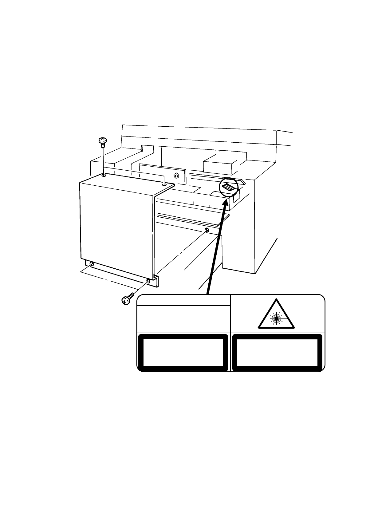
Lithium Batteries (Memory Back-up)
DANGER
INVISIBLE LASER RADIATION
WHEN OPEN AVOID DIRECT
EXPOSURE TO BEAM
CAUTION
LASER RADIATION WHEN
OPEN AVOID EXPOSURE
TO BEAM
VORSICHT
UNSICHTBARE LASERSTRAHLUNG,
WENN ABDECKNG GEOFFNET
NICHT DEM STRAHL AUSSETZEN
CAUTION:
The danger of explosion exists if a battery of this type is incorrectly replace d.
Replace only with the same or an eq uiva lent type recommended by th e
manufacturer. Discard used batteries in accordance with the manufa ctu rer’s
instructions.
Page 3

CONTENTS
1. OVERALL MACHINE INFORMATION
1.1. SPECIFICATIONS . . . . . . . . . . . . . . . . . . 1-1
1.2. FEATURES . . . . . . . . . . . . . . . . . . . . . 1-2
1.3. COMPONENT LAYOUT . . . . . . . . . . . . . . . . 1-5
1.4. OVERALL MACHINE CONTROL . . . . . . . . . . . . 1-5
1.5. VIDEO DATA PATH . . . . . . . . . . . . . . . . . . 1-6
1.5.1. Transmission . . . . . . . . . . . . . . . . . . . 1-6
1.5.2. Recept ion . . . . . . . . . . . . . . . . . . . . 1-6
1.6. Power Distributi on . . . . . . . . . . . . . . . . . . 1-7
1.6.1. Memory Back-up Circuit . . . . . . . . . . . . . . 1-7
2. DETAILED SECTION DESCRIPTIO N S
2.1. SCANNER . . . . . . . . . . . . . . . . . . . . . 2-1
2.2. PRINTER . . . . . . . . . . . . . . . . . . . . . . 2-3
1. Laser Optics . . . . . . . . . . . . . . . . . . . 2-3
2. Paper Feed . . . . . . . . . . . . . . . . . . . . 2-3
3. Fusing Unit . . . . . . . . . . . . . . . . . . . . 2-5
2.3. PCBs AND THEI R FUNCTIONS . . . . . . . . . . . . . 2-7
2.3.1. FCU . . . . . . . . . . . . . . . . . . . . . . 2-7
3. INSTALLATION
3.1. INSTALLING OPTIONAL UNITS . . . . . . . . . . . . . 3-1
3.1.1. Lower Cassette . . . . . . . . . . . . . . . . . . 3-1
3.1.2. Hard Disk . . . . . . . . . . . . . . . . . . . . 3-2
3.2. INITIAL PROGRAMMING . . . . . . . . . . . . . . . 3-4
Page 4

4. SERVICE TABLES AND PROCEDURES
4.1. SERVICE LEV E L FUNCTIONS . . . . . . . . . . . . . 4-1
4.1.1. Bit Switch Prog ramming (Function 01) . . . . . . . . . 4-1
4.1.2. System Parame te r L ist (Fun ction 02) . . . . . . . . . 4-2
4.1.3. Error Code Display (Fun ction 03) . . . . . . . . . . . 4-2
4.1.4. Service Monitor Report (Function 04) . . . . . . . . . 4-2
4.1.5. Protocol Dump (Fu nct ion 05) . . . . . . . . . . . . 4-2
4.1.6. RAM Display/Rewrite/P rintout (Function 06) . . . . . . 4-3
4.1.7. Checking the Coun te rs (Fu nct ion 07) . . . . . . . . . 4-4
4.1.8. Clearing the Coun te rs (Fu nct ion 08) . . . . . . . . . . 4-4
4.1.9. NCU Parameters (Function 09) . . . . . . . . . . . . 4-4
4.1.10. Modem/DTMF Tone Tests (Function 09) . . . . . . . . 4-5
4.1.11. Operation Panel Tests (Function 10) . . . . . . . . . 4-5
4.1.12. Scanne r Tests (Function 11) . . . . . . . . . . . . 4-6
4.1.13. Printe r Tests (Function 12) . . . . . . . . . . . . . 4-6
4.1.14. RAM Tests (Function 13) . . . . . . . . . . . . . . 4-7
4.1.15. Service Station Telephone Numbe r (Fun ction 14) . . . . 4-7
4.1.16. Serial Numbe r (Fu nct ion 15) . . . . . . . . . . . . 4-8
4.1.17. File Transfer (Funct ion 16 ) . . . . . . . . . . . . . 4-8
4.1.18. Hard Disk Initialization (Function 17) . . . . . . . . . 4-8
4.1.19. Group 4 Commu nica tion Parameters (Function 18) . . . 4-8
4.1.20. Programming th e CSI (Function 19) . . . . . . . . . 4-9
4.1.21. Setting the Teleph on e L ine Type (Function 20 ) . . . . . 4-9
4.2. BIT SWITCHES . . . . . . . . . . . . . . . . . . . 4-10
4.3. NCU PARAMETERS . . . . . . . . . . . . . . . . . 4-27
4.4. DEDICATED TRANSMISSION PARAMETERS . . . . . . . 4-43
4.4.1. Programming Procedure . . . . . . . . . . . . . . 4-43
4.4.2. Parameters . . . . . . . . . . . . . . . . . . . 4-44
4.5. SERVI CE RAM ADDRESSES . . . . . . . . . . . . . . 4-47
4.6. SPECIAL TOOLS AND LUBRICANTS . . . . . . . . . . 4-51
4.7. PM TABLE . . . . . . . . . . . . . . . . . . . . . 4-52
Page 5

5. REPLACEMENT AND ADJUSTMENT
5.1. SCANNER . . . . . . . . . . . . . . . . . . . . . 5-1
5.1.1. Xenon Lamp . . . . . . . . . . . . . . . . . . . 5-1
5.2. DEVELOPMENT . . . . . . . . . . . . . . . . . . . 5-1
5.2.1. Develop men t Unit . . . . . . . . . . . . . . . . . 5-1
5.3. PCBs . . . . . . . . . . . . . . . . . . . . . . . 5-1
5.3.1. Operation Panel PCB [D] . . . . . . . . . . . . . . 5-1
6. TROUBLESHOOTING
6.1. SERVICE CALL CONDITIONS . . . . . . . . . . . . . 6-1
6.2. ERROR CODES . . . . . . . . . . . . . . . . . . . 6-3
Page 6

OVERALL MACHINE INFORMATION June 19th, 1993
SPECIFICATIONS
1. OVERALL MACHINE INFORMATION
1.1. SPECIFICATIONS
Type
Desktop transceiver
Circuit
PSTN, PABX
Connection
Direct couple
Document Size
Length: 105 - 1200 mm [4.1 - 47.2 ins]
Up to 100 m [328 ft] after adjustment
Width: 148 - 304 mm [5.8 - 12.0 ins]
Thickness: ADF 0.05 to 0.2 mm
Manual Feed 0.04 to 0.4 mm
Document Feed
Automatic feed, face down
ADF Capacity
50 sheets (using 80 g/m
Scanning Method
Flat bed, with CCD
Maximum Scan Width
296 mm [11.7 ins] ± 1%
Scan Resolution
Main scan: 200 dpi
Sub scan:
Standard 100 dpi
Detail 200 dpi
Fine 400 dpi
Memory Capacity
ECM: 128 kbytes (double buffer)
SAF: Base machine - 1 Mbyte (62 pages),
with optional extra 1 Mbyte or 2 Mbytes
(max 123 or 185 pages respectively), or 20
Mbyte hard disk (1,200 pages total)
Compression
MH, MR, EFC, MMR, SSC
Storage to SAF memory for tx: MH
MMR only with ECM
2
paper)
Data Rate
14,400/12,000/9,600/7,200/4,800/2,400 bps;
automatic fallback
I/O Rate
With ECM: 0 ms/line
Without ECM: 5, 10, 20, or 40 ms/line
Transmission Time
6 s at 14,400 bps (G3 ECM) for a CCITT #1
test document (Slerexe letter) using standard resolution
Printing System
Laser printing, using the Ricoh CS (Compact
Seamless) Engine, plain paper, dry toner
Paper Size
Standard Cassette
Europe: A4, A5, B4
Asia: A4, A5, F, F4, B4
Lower Cassette
Europe: A4, A5, B4
Asia: A4, A5, F, F4, B4
Maximum Printout Width
210 mm [8.3 ins]
250 mm [9.8 ins] if a lower cassette is installed
Maximum Printer Resolution
Main scan: 400 dpi
Sub scan: 400 dpi
Power Supply
220 - 240 Vac, 50 Hz
Power Consumption (Base Machine Only)
Standby: 25 W Transmit: 35 W
Receive: 250 W Copying: 290 W
Operating Environment
Temperature: 17 - 28 °C [63 - 82 °F]
Humidity: 40 - 70 %Rh
Dimensions (W x D x H)
496 x 477 x 305 mm [19.5 x 18.8 x 12.0 ins]
Excluding handset, trays, and optional units
Modulation
V.33/V.17 (TCM), V.29 (QAM), V.27ter
(PHM), V.21 (FM)
Protocol
Group 3 with ECM, Group 4 kit available
Weight
19 kg [41.8 lbs]
Excluding handset, trays, and optional units
1-1
Page 7
June 19th, 1993 OVERALL MACHINE INFORMATION
FEATURES
1.2. FEA TURES
KEY: O = Used, X = Not Used,
A = With optional memory or hard disk only,
B = With lower cassette only,
C = With Group 4 kit only,
G = Not used in Germany,
S = Service mode in some countries
Equipment
ADF O
Bar code reader X
Built-in handset X
Cabinet X
Connection for ans. machine X
Connection for handset O
Cutter X
Handset (option only in Europe) O
Hard disk (option only) O
Magnetic card reader X
Manual feed mechanism O
Marker O
Microphone X
Monitor speaker O
Remaining memory indicator O
Speakerphone X
Video Processing Features
Contrast O
Halftone (Basic & Error Diffusion) O
MTF O
Reduction O
Resolution O
Smoothing to 16 x 15.4 l/mm O
Communication Features - Auto
Automatic fallback O
Automatic redialling O
Confidential reception A
Dual Access O
Substitute reception O
Transmission Reserve X
Communication Features -
User Selectable
Action as a transfer broadcaster A
AI Redial O
Alternative Destination X
Answering machine X
Authorized Reception O
Auto-answer delay time X
Auto dialling (pulse or DTMF) O
Auto Document X
Automatic Voice Message X
Auto-note X
Batch Transmission (max 200
batches)
Broadcasting O
Chain Dialling O
Communication Result Display O
Confidential ID Override O
Confidential Transmission O
Direct Fax Number Entry O
Economy Transmission O
Economy Transmission Time O
Forwarding (5 stations) A
Free Polling O
Groups (10 groups) O
Group Transfer Station O
Hold X
ID Transmission Option O
Immediate Redialling O
Immediate transmission O
Keystroke Programs O
Mailbox X
Memory transmission (this is the
default mode)
Multi-step Transfer O
Next Transfer Station C
Notify X
On Hook Dial O (G)
Page Count O
Personal Codes O
Personal Codes with Conf ID O
Polling Reception O
Polling Transmission O
Polling tx file lifetime in the SAF O
Quick Dial (32 stations) O
O
O
1-2
Page 8
OVERALL MACHINE INFORMATION June 19th, 1993
FEATURES
Communication Features -
User Selectable
Reception modes (Fax, Tel,
Reduction O
Remote control features X
Remote Transfer X
Restricted Access (50 codes,
without cards)
Secured Polling O
Secured Polling with Stored ID
Override
Secure Transmission O
Send Later O
Silent ringing detection X
Speed Dial (100 stations) O
Telephone Directory O
Tonal Signal Transmission O
Transfer Request O
Transmission Deadline O
Turnaround Polling X
Two- step Transfer C
Voice Request (immed. tx only) O
Communication Features -
Service Selectable
AI Short Protocol O
Auto-reduction override option O
Busy tone detection O
Closed Network (tx and rx) O
Continuous Polling Reception O
Dedicated tx parameters O
ECM O
EFC O
Inch-mm conversion O
MV1200 compatibility X
Page retransmission O
Page separation mark O
Protection against wrong conn. O
Resol’n stepdown override option X
Short Preamble O
Well log O
Auto) O
O
O
Other User Features
Area Code Prefix O
Auto Service Call O
Center mark O
Chequered mark O
Clearing a memory file O
Clearing a polling file O
Clock O
Confidential ID O
Copy mode O
Counters O
Country code O
Destination Check O
Direct entry of names O
Function Programs O
ID Code O
Label Insertion O
Language Selection O
LCD contrast control Service
Memory Lock A
Memory Lock ID A
Modifying a memory file X
Multi Sort Document Reception A
Multicopy mode A
Night Timer O
Own telephone number O
Printing a memory file O
RDS on/off O
Reception Mode Switching Timer X
Reception Time (non-memory rx
only)
Remote ID X
Reverse Order Printing A
RTI, TTI, CSI O (S)
Secure ID O
Speaker volume control O
Specified Cassette Selection B
Substitute reception on/off O
Telephone line type O (S)
TTI on/off O
User Function Keys O
User Parameters O
Wild Cards O
O
1-3
Page 9
June 19th, 1993 OVERALL MACHINE INFORMATION
FEATURES
Reports - Automat ic
Charge Control Report X
Communication Failure Report O
Confidential File Report O
Error Report O
Memory Storage Report O
Mode Change Report X
Polling Clear Report O
Polling Reserve Report O
Polling Result Report O
Power Failure Report O
Journal O
Transfer Result Report O
Transmission Deadline Report O
Transmission Result Report O
Reports - User-initiated
Authorized Reception List O
Charge Control Report X
File List O
Forwarding List A
Group List O
Personal Code List O
Program List O
Quick Dial List O
Specified Cassette Selection List B
Speed Dial List O
Journal O
Transmission Status Report X
User Function List O
User Parameter List O
Service Mode Features
Operation panel test O
Printer mechanism test X
Printer test patterns O
Programmable attenuation X
Protocol dump list O
RAM display/rewrite O
RAM dump O
RAM test O
Ringer test X
Scanner lamp test O
Scanner mechanism test O
Sensor initialization X
Serial number O
Service monitor report O
Service station number O
System parameter list O
Technical data on the Journal O
Thermal head parameters X
Transmission Status Report X
Memory Files
Max. number of files: 200
Max. number of stations/ file : 20 0
Max. number of stations ove rall: 500
Max. number of pages overall: 1, 200
Service Mode Features
Back-to-back test O
Bit switch programming O
Buzzer test O
Cable equalizer O
Comm. parameter display O
Counter check O
DTMF tone test O
Echo countermeasure O
Error code display O
File Transfer O
LCD contrast adjustment O
Memory file printout (all files) O
Modem test O
NCU parameters O
1-4
Page 10
OVERALL MACHINE INFORMATION June 19th, 1993
COMPONENT LAYOUT
1.3. COMPONENT LAYOUT
The only diff ere nce is in the document width se nso r, which has an A3-width
sensor and a B4-width se nso r. See section 2 for a drawing.
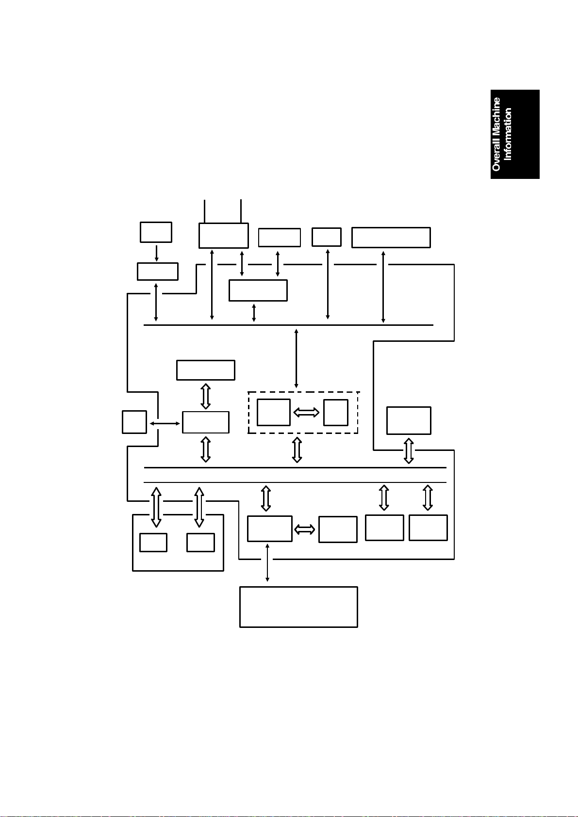
1.4. OVERALL MACHINE CONTROL
HandsetLine
SBU
(CCD)
Scanner
Sensors
Operation
Panel
NCU
CONTROL SIGNALS
Video Processing
Memory
Video
Processor
Speaker
Modem
CPU
DATA AND ADDRESS BUS
PSU
Port
Scanner and Printer Drive
Components and Sensors
FCU
I/O
RS-232C
Interface
Laser
Interface
Page
Memory
SAF
Memory
ECM
Memory
RAMROM
MBU
Laser Diode Driver
Main Scan Start Detector
Interlock Switch
The cpu on the FCU board controls the machine, as shown in the above
drawing. There is no modem board in th e machine; the modem consists o f a
chip on the FCU board that carries out all the analog and digital functions of a
fax modem.
1-5
Page 11
June 19th, 1993 OVERALL MACHINE INFORMATION
VIDEO DATA PATH
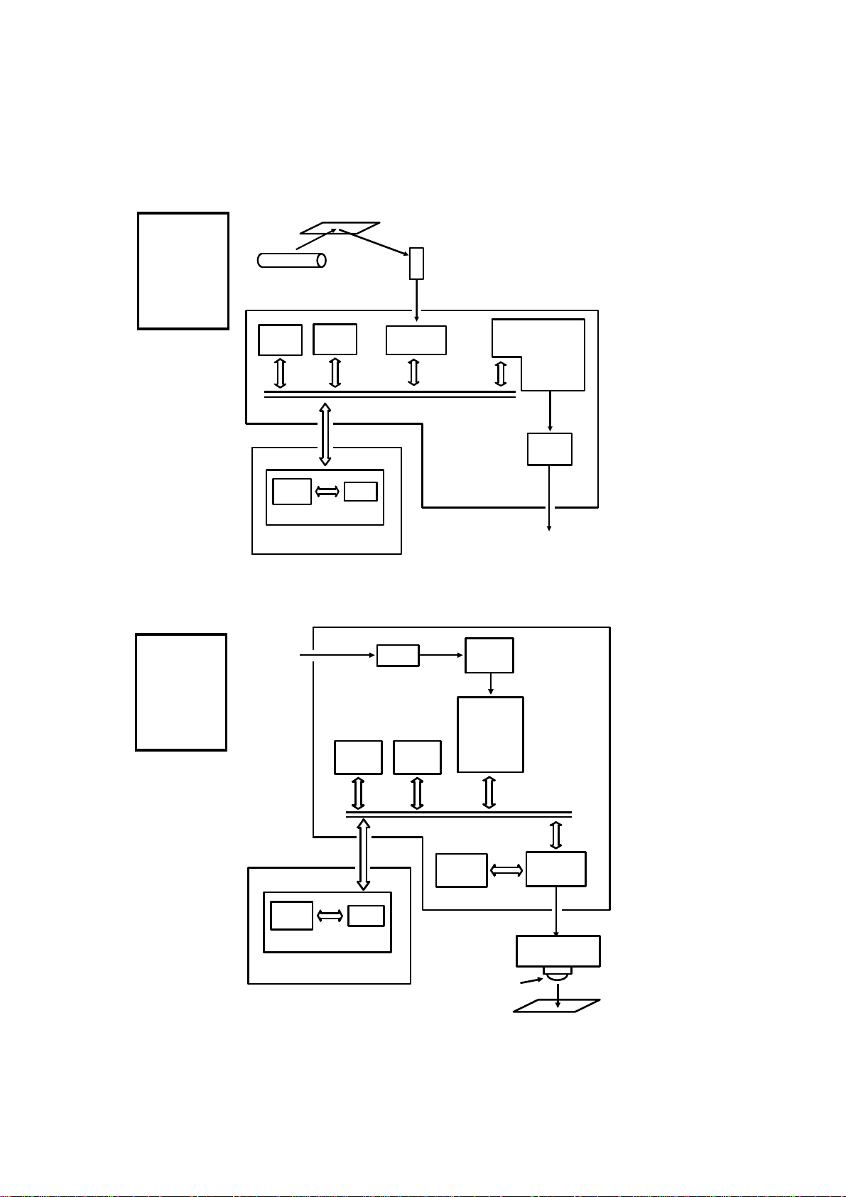
1.5. VIDEO DATA PATH
1.5.1. Transmission
Original
Reference:
Group 3
Facsimile
Manual,
section
1-3-1
Xenon
Lamp
ECM
Memory
Line
Buffer
SAF
Memory
RAM
MBU
FIFO
Analog Signal
Video
Processor
The following diagrams show
the data path for this mod el.
CCD
CPU
Modem
FCU
To the
Network
(via the NCU)
1.5.2. Reception
Reference:
Group 3
Facsimile
Manual,
section
1-3-2
From the
Network
(via the NCU)
Line
Buffer
RAM
MBU
FCU
Memory
SAF
FIFO
Filter
HYBRID IC
Memory
ECM
Page
Memory
Laser Diode
Modem
CPU
Laser
Interface
Laser Diode
Driver
1-6
Copy Paper
Page 12
OVERALL MACHINE INFORMATION June 19th, 1993
Power Distribution
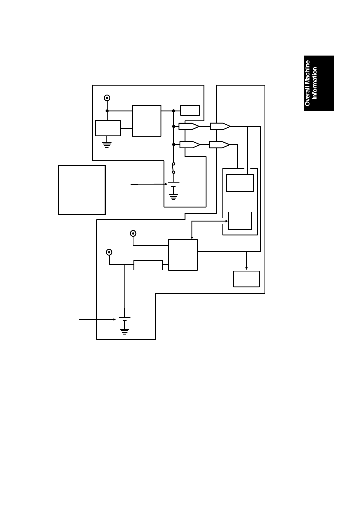
1.6. Power Distribution
1.6.1. Memory Back-up Circuit
Reference:
Group 3
Facsimile
Manual,
section 1-4-3,
Circuit type 1
+5V
Voltage
Detector
+24V
[A]
+5V
Switching
Circuit
Regulator
MBU
RAM
1-9
1-7
Battery
Switch
Battery
Switching
Circuit
FCU
17-9
17-7
Real Time
Clock
CPU
Memory
Monitor
SAF
Memory
[B]
Battery
The battery [A] on the MBU backs up the RA M on the MBU, which con ta ins
system parameters. It also backs up the rea l time clock in t he cpu . This battery is not rechargeable. CN1-7 te lls the cpu whe th er the ba ck-up powe r
(CN1-9) comes from the battery or fro m t he +5 V power supply.
A rechargeable battery [B ] on the FCU board backs up the SAF memo ry and
the real time clock for 1 hour. While the main power is on, the +24V supply recharges the battery. There is no battery switch.
If there is data in the SAF memory, the rechargeable batt ery [B ] also backs
up the real time clock, to preserve the MBU battery.
1-7
Page 13
DETAILED SECTION DESCRIPTIONS June 19th, 1993
SCANNER
2. DETAILED SECTION DESCRIPTIONS
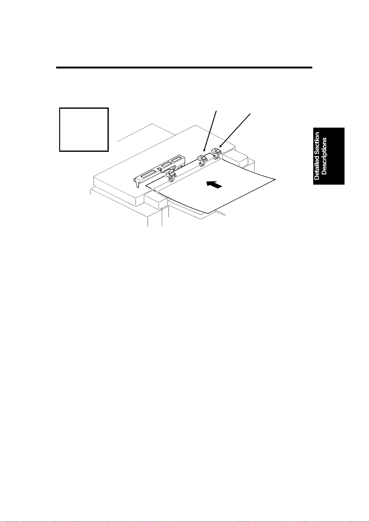
2.1. SCANNER
Document Table
Reference:
Group 3
Facsimile
Manual,
section 2-1-1.
• The scanner is A3-width [11.7"], with a B4 document widt h d etector [A]
[A]
[B]
and an A3 document width sensor [B] .
Resolution
This machine scans in dots per inch , to meet Group 4 stand ards. The various
scan resolutions are ach ieved as follows.
Standard - Immediate transmission: The tx motor feeds the documen t a t 200
lines per inch. The video processor executes OR processing t o co nve rt t he
data into 100 lines per inch .
Memory transmission: The motor feeds the docu men t at 10 0 lines per in ch,
and no OR processing is needed.
Detail - The tx motor fee ds th e do cument at 200 lines pe r in ch. There is no
OR processing, and the da ta is transmitted at 200 lines pe r inch.
Fine - The tx motor feeds the documen t and tra nsmits data at 400 lines per
inch. If the other t ermin al cannot receive at this resolut ion , alternate lines of
data are deleted, so the effective resolution of the transmitted da ta is 200
lines per inch.
2-1
Page 14

June 19th, 1993 DETAILED SECTION DESCRIPTIONS
SCANNER
Document Jam Conditions
The cpu detects a document jam if one of the following cond itions occurs.
• The scan line sensor does not switch on within 5 s of the tx motor start-
ing.
• The scan line sensor does not turn off afte r t he maximum do cume nt
length has been fed since it turn ed on; this is 12 s (stan da rd reso lut ion),
24 s (detail), or 48 s (fine) for a 1.2 m long document.
• The scan line sensor switches on while the document sensor is off.
• The document width sensor switches on while the document sensor is
off.
• The scan line sensor does no t tu rn on within 2 s of the end of stamping,
if the document senso r is on.
2-2
Page 15
DETAILED SECTION DESCRIPTIONS June 19th, 1993
PRINTER
2.2. PRINTER
1. Laser Optics
Hexagonal mirror motor speed: 9, 26 7. 7 rpm (G3 and G4 l/mm mod e), 9448. 8
rpm (G4 dpi mode)
2. Paper Feed
Page Separation and Data Reducti on
Incoming pages that are similar in lengt h to the copy pa per ma y be red uce d
in the sub-scan direction to fit on the paper. Whether or not this happens depends on the settings of bits 1 and 2 of bit switch 02 .
Reduction Enabled
If bit 2 of bit switch 02 is at 0, the data will be reduced in the page memory to
fit on the copy paper. However, data will only be redu ced if the leng th of th e
incoming page is between 5 mm shorter and a certain maximum length. This
maximum incoming page lengt h that can be reduced depen ds on the co py paper size and on the reduction ratio sto red in RAM addresses 00014F and
000150.
Each paper size can be progra mmed wit h a sep arate reduction ratio. In ea ch
of the two RAM addresses, th ere is one bit for each p ossible paper size. The
combination of the bit sett ing s det ermines the ratio for that paper size.
Bit 7: Not used Bit 5: Legal Bit 3: A4 Bit 1: B5
Bit 6: B4 Bit 4: F4 Bit 2: Letter Bit 0: A5
The ratio is determined in accordan ce with the follo wing tab le.
Bit in
00014F
Bit in 000150 0 0 1 1
0: Not used 1: 4/3 0: 8/7 1: 12/11
2-3
Page 16
June 19th, 1993 DETAILED SECTION DESCRIPTIONS
PRINTER
The following table shows the maximum incoming page length s that can be
reduced for each copy p aper size. All lengths are in millimet res. The factory
setting of the reduction ratio is 4/3.
Copy
Paper Type
A5 148 190.7 163.4 156
B5 182 236 202.3 193.1
Letter 279.4 365.9 313.6 299.3
A4 297 389.3 333.7 318.5
F4, F 330.2 433.6 371.7 354.8
Legal 355.6 467.5 400.7 382.5
B4 364 478.7 410 391.6
Copy Paper
Length
Maximum reducable incoming page lengths
Ratio = 4/3 Ratio = 8/7 Ratio = 12/11
The values are calculate d as follows.
Maximum incoming page lengt h that can be reduced =
(Copy Paper Length - 5) x Reduction Ratio
For example, for A 5 wit h a reduction ratio o f 4/3
Max incoming data length = (148 - 5) x 4/3 = 1 90.7
Incoming pages that are longer than the maximum le ngth will not be reduced ,
but will be printed on two pages and treated in accord an ce with the sett ing of
bit 1 of bit switch 02. If this bit is 1, the bottom few lines of the page will be repeated at the top of the next page. If this bit is 0, the next page will continue
from where the first page left off.
Reduction Disabled
If bit 2 of bit switch 02 is at 1, the data will not be reduced . Howe ver, if the in-
coming page is up to x mm longer than the copy pa pe r, the excess portion
will not be printed. The value of x can be from 0 to 15 mm. It is determined by
the setting of RAM address 00015 1 (cop y mode : bit s 3 to 0, receive mode :
bits 7 to 4; bits 3 and 7 are the most signif icant bits).
Hex value Value of x
0 0
1 1
and so on until
15 15
Messages more than x mm longer than the copy paper will be printed out on
two pages in accordance with the sett ing of bit 1 of bit switch 02 , as explained above.
2-4
Page 17
DETAILED SECTION DESCRIPTIONS June 19th, 1993
PRINTER
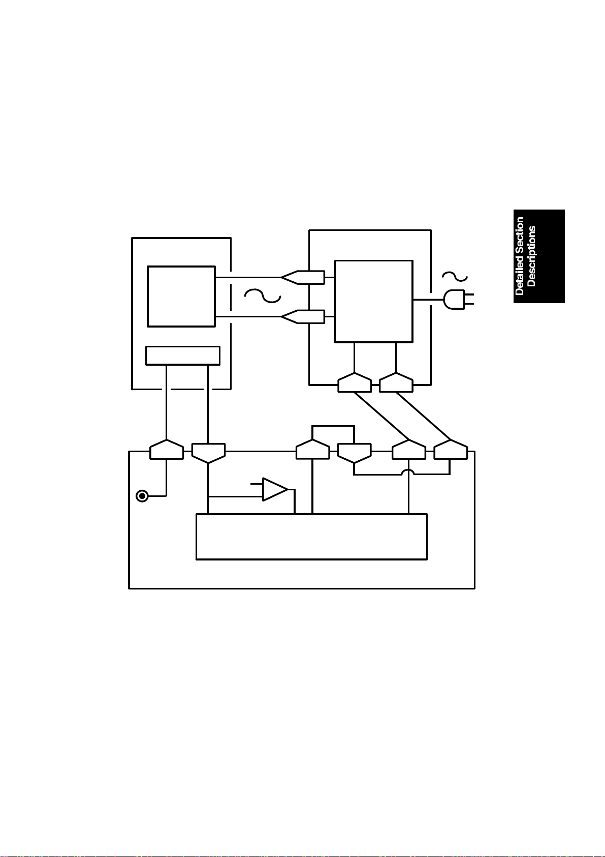
3. Fusing Unit
Fusing Unit Control Temperatures
Stancby temperature: 80 °C
Printing start temperature: 150 °C
Maximum printing temperat ure : 17 0 °C (monitored by a comparato r )
Thermistor maximum: 280 °C
Thermostat maximum: 400 °C
FUSING UNIT
Fusing
Lamp
Thermistor
36-2
+5V
36-1
LIVE
NEUTRAL
170 C [A]
4-1,4
4-3,6
36-3
I/O
Port
PSU
AC Switching
Circuit
3-1
36-4
3-2
1-8
Main
Power
Supply
1-7
FCU
The circuit shown in the above dia gram controls the fusing unit .
• The I/O Port monito rs the fusing unit temperature at CN36 -1.
• The signal from the compa r at or [A] remains high if the fusing unit tem-
perature is below 170 °C.
• The I/O Port switches th e fu sing unit on/off usin g the signal on CN1-8.
• If the thermistor is accidentally disconnect ed, th e link betwe en CN3 6-3
and CN36-4 will also be bro ken. When the cpu d et ects this, an Auto
Service Call will be sent.
2-5
Page 18

June 19th, 1993 DETAILED SECTION DESCRIPTIONS
PRINTER
Standby mode
• If the fusing lamp is belo w 8 0 °C, th e I/ O Po rt makes CN1-8 go high.
This switches on the fusing lamp.
• If the fusing lamp goes above 80 °C, CN1-8 goes lo w, which switches
off the fu sing lamp.
Printing
• When a ringing signal is detect ed, CN1-8 goes high, to switch on the
fusing lamp. Also, t he o zone fan switches on.
• During printing, the temperature is kept at 170 °C. If the temperature
rises above 170 °C, the output from the comp arator changes state. This
causes CN1-8 to go low, which switches off the fusing lamp.
• If the comparator fails, there are additional safety cutoffs at 280 °C (th er-
mistor) and at 400 °C (thermostat).
After printing
• When the fusing lamp temp erature falls back below 150 °C, th e ozo ne
fan switches off.
Service Note
When an error occurs, the I/O Port switches off the fusing lamp by raising
CN1-7 to high. The print er will b e d isab led , a nd an Auto Service Call will be
sent to the service station (t he me ssag e will be HOT ROLLER DOWN). Details concerning these erro rs are give n in section 6-1 (Service Call Conditions).
2-6
Page 19
DETAILED SECTION DESCRIPTIONS June 19th, 1993
PCBs AND THEIR FUNCTIONS
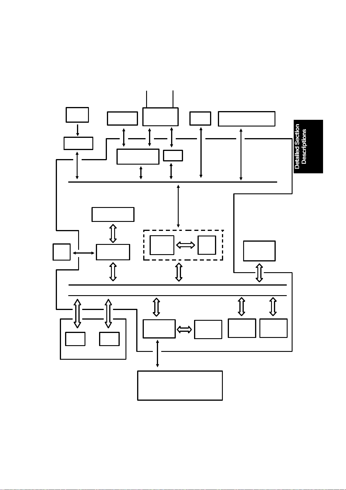
2.3. PCBs AND THEIR FUNCTIONS
2.3.1. FCU
HandsetLine
SBU
(CCD)
Scanner
Sensors
Operation
Panel
Speaker
CONTROL SIGNALS
Video Processing
Memory
Video
Processor
Modem
NCU
CPU
HIC
PSU
Port
Scanner and Printer Drive
Components and Sensors
FCU
I/O
RS-232C
Interface
MBU
DATA AND ADDRESS BUS
Laser
Interface
Page
Memory
SAF
Memory
ECM
Memory
RAMROM
Laser Diode Driver
Main Scan Start Detector
Interlock Switch
2-7
Page 20

June 19th, 1993 DETAILED SECTION DESCRIPTIONS
PCBs AND THEIR FUNCTIONS
1. CPU (MFCP)
• 65C02 compatible microprocessor
• Interrupt control
• DMA control
• Data compression and re con struction (high speed MH coding fo r 2. 8-
second scanning)
• Real time clock (battery backed-up)
• Memory control
• Control of all mechanisms (dire ctly or th rou gh othe r chip s)
• NCU control (through the I/O Po rt)
2. I/O Port (MIOP)
• Clock control
• Sensor monitoring (includ ing A/D con version whe re necessa ry)
• Tone detection
• Motor drive
• Operation panel con tro l
• Laser Interface control
3. Laser Interface (LIF)
• Page memory control
• Laser diode contro l
• Smoothing
4. Modem
• Modulation/demodulation (analog and digital operations)
5. Video Process or (VP P )
• Analog/digital vide o sign al processing
6. Hybrid IC (HIC)
• Filters
• Amplifiers
7. RAM
• 256k for ECM and system RAM (no back-up)
• 1 Mbyte SAF memory (with battery back-up)
• 1 Mbyte page memory
• 24 kbyte image memory for th e VPP
2-8
Page 21
INSTALLATION August 19th, 1992
INSTALLING OPTIONAL UNITS
3. INSTALLA TION
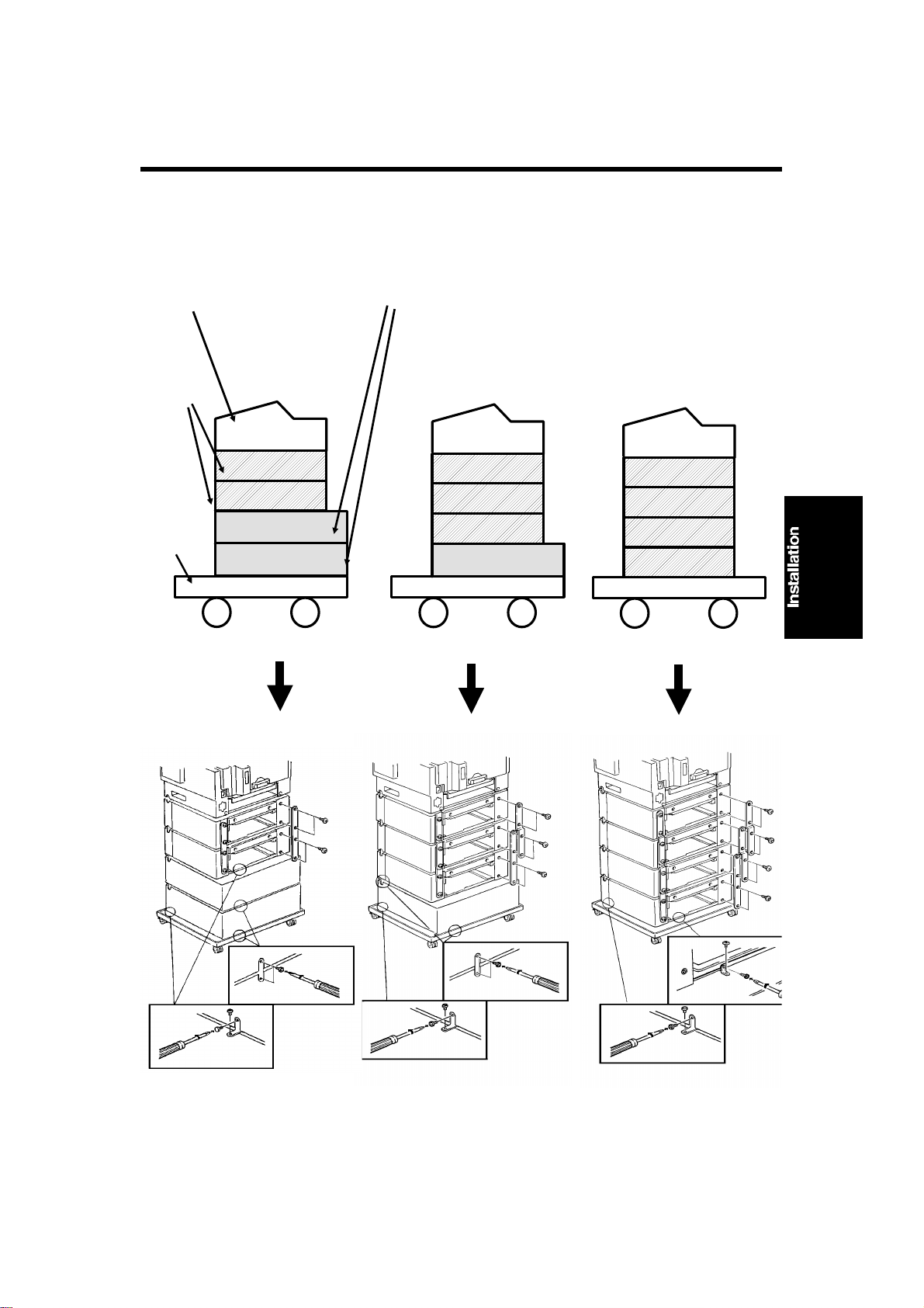
3.1. INSTALLING OPTIONAL UNITS
Up to 4 of these paper feed units can be added
3.1.1. Lower Cassette
Machine
Drawers
to the machine. However, if more than one is installed, you have to install drawer and base
units in one of the following ways.
Paper
Feed
Units
Base
2 Paper
Feed Units
3 Paper
Feed Units
4 Paper
Feed Units
3-1
Page 22
[D]
[C]
August 19th, 1992 INSTALLATION
INSTALLING OPTIONAL UNITS
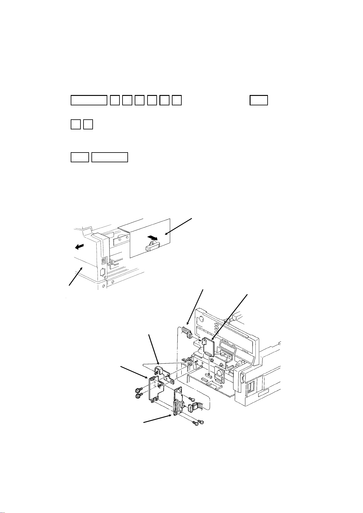
3.1.2. Hard Disk
SAF Memory Initialization
1. Function 6 0 1 9 9 1 then immediately Yes
2. 0 1
3. Set bit 2 of bit switch 00 to 1.
4. Yes Function
Installation Procedure
Switch off the power and unplug the machine from the wall socket. Then remove the cassettes.
[B]
[A]
[F]
[G]
[E]
3-2
Page 23
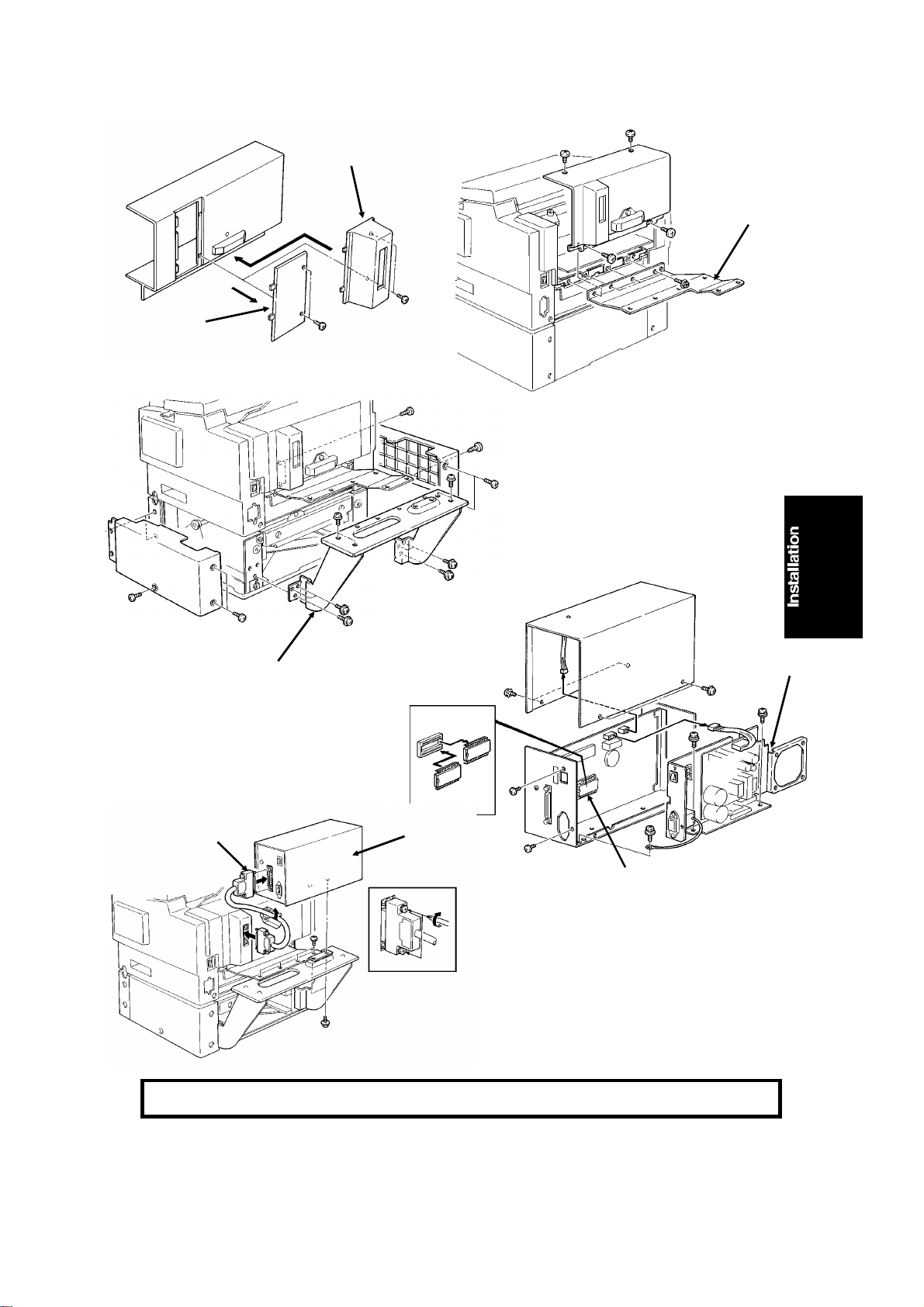
[H]
INSTALLATION August 19th, 1992
INSTALLING OPTIONAL UNITS
[ I ]
[J]
Before attaching [K], remove the side covers of
the paper feed unit.
Then, after attaching [K],
put the covers back.
[K]
[O]
[N]
[M]
Change the ROM [M]
on the HDIF board before reassembling the
hard disk unit.
Caution: Do not plug in or switch on until everything is connected up.
[L]
3-3
Page 24

August 19th, 1992 INSTALLATION
INITIAL PROGRAMMING
Software Initialization
1. Function 6 0 1 9 9 1 , then immediately Yes
2. 0 1
3. Set bit 0 of bit switch 0D to 1.
4. Yes Function
5. Tu rn off the power, the n tu rn on the power after a fe w seconds.
3.2. INITIAL PROGRAMMING
Check the following:
• Are the country codes for NCU parameters (Fun ctio n 09, parame te r 00)
and bit switch settings (bit switch 0F) correct fo r the coun try of insta llation?
• Are the NCU jumper settings correct for th e cou nt ry of inst allation?
• Do any bit switch or other setting s have to be chan ge d to match line
conditions or user requirements?
• Have the correct operation pane l deca ls a nd Quick Dial sheets been in-
stalled from the language kit?
• Have you programmed th e serial number (Function 15, sect ion 4-1-18)?
In some countries, the use r ca nn ot prog ram the following items, so program
them before you lea ve th e machine.
• Telephone Line Type (Function 19, section 4-1 - 23 )
• CSI (Function 20, section 4-1-2 2)
The user should program the follo wing items after installation :
• Telephone Line Type (in some countries, this is not a user adjustment )
• RTI, TTI, and CSI (in some coun trie s, CSI is not a u ser a dju stme nt)
• ID Codes (ID Code, Confidential ID, Memory Lock ID)
• The fax machine’ s own telephone number
• Country code
• Area code prefix (if applicable)
• Date and Time
• Language Selection
3-4
Page 25
SERVICE TABLES AND PROCEDURES June 19th, 1993
SERVICE LEVEL FUNCTIONS
4. SERVICE TABLES AND PROCEDURES
4.1. SERVICE LEVEL FUNCTIONS
To enter service mode, press the following sequence of keys:
Function 6 0 1 9 9 1
then immediately Yes
SERVICE FUNCTION NO. _
01BIT SW. 02PARA LIST
03ERROR CODE 04SVC MONITOR
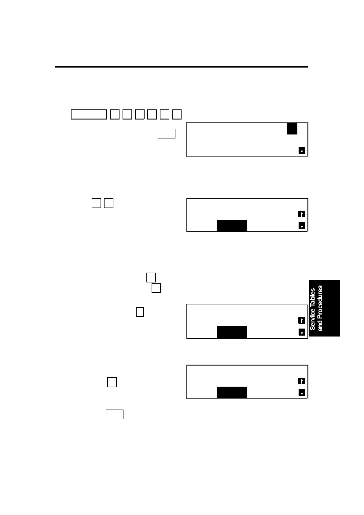
4.1.1. Bit Switch Programming (Function 01)
1. After entering se rvice mode,
press 0 1
BIT SWITCH
DF: 00000000
SW:00 00000000
Bit 7 is displayed at the left , an d bit 0 at the right. The de fa ult settings are
shown on the top line, and the current settings on the bottom.
2. • Increment bit switch: ↓
• Decrement bit switch: ↑
Example:
Display bit switch 3: ↓ x 3
BIT SWITCH
DF: 00000000
3. Adjust the bit switch.
Example: To change the value of
bit 7, press 7
4. Either:
• Adjust more bit switches - go to step 2.
• Finish - Yes
SW:03 00000000
BIT SWITCH
DF: 00000000
SW:03 10000000
4-1
Page 26

June 19th, 1993 SERVICE TABLES AND PROCEDURES
SERVICE LEVEL FUNCTIONS
4.1.2. System Parameter List (Function 02)
1. After entering se rvice mode,
press 0 2
G3 SYSTEM PARAMETER LIST
PRESS START
2. Start
3. After printin g, pre ss Function
4.1.3. Error Code Display (Function 03)
1. After entering se rvice mode,
press 0 3
ERROR CODE
CODE=0-14 JUL 10 15:15
2. Either:
• Scroll through the error co des using ↑ and ↓
• Finish - Yes
4.1.4. Service Monitor Report (Function 04)
1. After entering se rvice mode,
press 0 4
SERVICE MONITOR REPORT
2. Start
4.1.5. Protocol Dump (Function 05)
1. After entering se rvice mode,
press 0 5
G3 PROTOCOL DUMP LIST
PRESS START
PRESS START
2. Start
4-2
Page 27

SERVICE TABLES AND PROCEDURES June 19th, 1993
SERVICE LEVEL FUNCTIONS
4.1.6. RAM Display/Rewrite/Printout (Function 0 6)
1. After entering se rvice mode,
press 0 6
RAM NO. _
0.MEMORY R/W 1. MEMORY DUMP
2. Either:
• Display or rewrite RAM data: 0
Go to step 3.
• Print a RAM dump list: 1 . Go
to step 6.
MEMORY R/W
ADDRESS= 000000 DATA=FF
MEMORY DUMP
ADD. H - ADD. FFH
3. Input the address th at you wish to
see.
Example: 0 0 1 1 2 2
If necessary, use ↑ and ↓ to
MEMORY R/W
ADDRESS= 001122 DATA=00
increment or decrement the RAM
address.
4. If you wish to change the con te nt s
of the RAM address, press → to
move the cursor to the data side.
Then input the new data.
Example: F F
MEMORY R/W
ADDRESS= 001122 DATA= FF
5. Either:
• View more addresses - ← then go to step 3.
• Finish - Yes . Go to step 2.
6. Input the range of addresses that you wish to print.
Example: Addresses 22AA00 to 22BBFF
2 2 A A 2 2 B B Start
4-3
Page 28

June 19th, 1993 SERVICE TABLES AND PROCEDURES
SERVICE LEVEL FUNCTIONS
4.1.7. Checking the Counters (Function 07)
1. After entering se rvice mode,
press 0 7
COUNTER R/W NO. _
0 COUNTER 1 PM COUNTER
2 CTM COUNTER 3 OPU COUNTER
2. Either:
• Check the scanned, printed, transmitted, and received page counters,
and the printer and scanner jam counters: 0 . (To see the jam
counters, press 0 then ↓ . )
• Check the PM counter: 1
• Check the CTM counter: 2
• Check the OPU counter: 3
3. To change the contents of a counter, press → until the required
counter is highlighte d on the scre en, then input the new value.
4.1.8. Clearing the Counters (Function 08)
1. After entering service mode,
press 0 8
COUNTER CLEAR NO. _
0 PM COUNTER 1 CTM COUNTER
2 OPU COUNTER
2. Either:
• Clear the PM counter: 0
• Clear the CTM counter: 1
• Clear the OPU counter: 2
4.1.9. NCU Parameters (Function 09)
1. After entering se rvice mode,
press 0 9
NCU NO. _
0 NCU 1 MODEM/DTMF
2. 0
4-4
NCU
NO.00= 019
PRESS YES/NO
Page 29

SERVICE TABLES AND PROCEDURES June 19th, 1993
SERVICE LEVEL FUNCTIONS
3. Scroll through the parameters using ↑ and ↓ .
Enter new values at the keypa d where necessary.
Example: Set NCU parameter 04 to 005.
↓ ↓ ↓ ↓ 0 0 5 Yes
4. To go to the n ext parameter: Yes
5. To finish: No Yes
Note: Parameter 00 is the Country Code, and Parameter 01 is th e Tx Level
(Input the value of the Tx level x -1 ; f or e xamp le, if the Tx level should
be -9 dB, input 9).
4.1.10. Modem/DTMF Tone Tests (Function 09)
1. After entering se rvice mode,
press 0 9 then 1
MODEM/DTMF
NO.01=V29 9600 BPS
PRESS START
2. Scroll through the available tests using ↑ and ↓ .
Example: To do an 1100 Hz tone test. ↓ ↓ ↓ Start
To finish a test: Stop
3. To finish: Yes x 2
4.1.11. Operation Panel Tests (Function 10)
1. After entering se rvice mode,
press 1 0
OP.PANEL NO. _
0 LED 1 ALARM
2 RINGER 3 LCD
2. Either:
• Test the LEDs on the operation pane l: 0 Start
• Test the alarm tone: 1 Start
• Test the ringer: This test is not use d in this machine.
• Test the LCD: 3 Start
4-5
Page 30

June 19th, 1993 SERVICE TABLES AND PROCEDURES
SERVICE LEVEL FUNCTIONS
3. To finish a test: Stop
4. To finish: Yes x 2
4.1.12. Scanner Tests (Function 11)
1. After entering se rvice mode,
press 1 1
SCANNER NO. _
0 XE LAMP 1 ADF
2. Either:
• Switch on the xenon lamp: 0 Start
• Test the auto document feeder: Place a shee t of paper in the document
feeder, then 1 Start
3. To finish a test: Stop
4. To finish: Yes x 2
4.1.13. Printer Tests (Function 12)
1. After entering se rvice mode,
press 1 2
PRINTER NO. _
0 P ATTERN 1 MECH TEST
2 FAN MOTOR 3 CTM MOTOR
2. Either:
PATTERN NO. _
• Print a test pattern : 0 . Go to
step 3.
• Test the printer mechanism: 1 Start
• Test the fan motor: 2 Start
• Test the CTM motor: First, remove the CTM, then pre ss 3 Start
0 DIAGONAL 1 1 DIAGONAL 2
2 VERTICAL 3 GRAND PRIX
To finish a test: Stop
4-6
Page 31

SERVICE TABLES AND PROCEDURES June 19th, 1993
SERVICE LEVEL FUNCTIONS
3. Press a key from 0 to 5, depending on the required pattern. Use ↑
and ↓ to see what pattern s are available.
4. Start
A test pattern is printed.
5. To finish: Yes x 2
4.1.14. RAM Tests (Function 13)
1. After entering se rvice mode,
press 1 3
RAM TEST NO. _
0 SRAM 1 SAF
2 PAGE MEMORY
2. Either:
• Test the SRAM: 0 Start
• Test the SAF: 1 Start
• Test the page memory: 2 Start
If there is a problem, a display of the following type will occur.
SAF
PRESS START
ADDRESS=300002 W=55 R=00
Keep a note of the information on the display, then press Start to resume
testing.
3. When the test has fin ishe d, "OK" is displayed. Press Yes to finish.
4.1.15. Service Station Telephone Number (Function 14)
1. After entering se rvice mode,
press 1 4
S.S.NO ENTER FAX NUMBER
NO
TO CANCEL
2. Input the telephone number of the service station that will receive Auto
Service calls from this machine.
Then press Yes .
If the ISDN Option kit has bee n inst alle d, press the Line Selector key to
select either G3 or G4 before inputting the number.
4-7
Page 32

June 19th, 1993 SERVICE TABLES AND PROCEDURES
SERVICE LEVEL FUNCTIONS
4.1.16. Serial Number (Function 15)
1. After entering se rvice mode,
press 1 5
SERIAL NO.
2. Enter the machine ’s serial no at the keypad.
To correct a mistake: No
3. If the display is correct: Yes
4.1.17. File T ra nsfe r (Functi on 16)
1. After entering se rvice mode,
press 1 6
FILE TRANSFER ENTER FAX NUMBER
NO
TO CANCEL
2. Input the teleph on e nu mbe r o f th e fax machine to which you wish to tra nsfer all the files. Then pre ss Yes Start .
If the ISDN Option kit has bee n inst alle d, press the Line Selector key to
select either G3 or G4 before inputting the number.
4.1.18. Hard Disk Initialization (Function 17)
1. After entering se rvice mode,
press 1 7
HD NO. _
0 INITIAL
2. 0
The hard disk is initialized.
4.1.19. Group 4 Communication Parameters (Functi on 18)
This function is described in the service manual for the optio nal I SDN kit.
4-8
Page 33

SERVICE TABLES AND PROCEDURES June 19th, 1993
SERVICE LEVEL FUNCTIONS
4.1.20. Programming the CSI (Function 19)
This procedure is for use in countrie s where CSI programming is a service
mode.
1. 1. After entering se rvice mode,
press 1 9
2. Input the CSI (not more than 20 dig-
CSI
CSI
YES
TO END
YES OR CLR . NO
its)
+44712121234
Note: If you wish to input a ’+’ sign to signify the international dial ac-
cess code, press 31 then 1
4. Yes Function
4.1.21. Setting the Telephone Line Type (Function 20 )
This procedure is for use in countries where telephone line type selection is a
service mode.
1. After entering se rvice mode,
PSTN LINE TYPE SELECT
press 2 0
PD TT
2. If the setting needs changing,
press ← or → until the re-
quired setting is highlighted in reverse video.
3. Yes Function
4-9
YES
TO END
Page 34

June 19th, 1993 SERVICE TABLES AND PROCEDURES
BIT SWITCHES
4.2. BIT SWITCHES
WARNING
Do not adjust a bit switch that is described as "Not used", as this
may cause the machine to malfunction or to operate in a manner
that is not accepted by local regulations. Such bits are for use only
in other areas, such as Japan.
Bit Switch 00
FUNCTION COMMENTS
0 MTF process
0: Enabled 1: Disabled
1 RAM reset level 2
1: Reset
2 RAM reset level 3
1: Reset
Note: RAM reset level
1 is a RAM
adjustment. It is not
described in this
manual.
3 Not used Do not change the factory setting.
4 Inclusion of technical
data on the TCR
0: No 1: Yes
5 Monitor speaker
during video data
communication (tx
and rx)
0: Disabled 1:
Enabled
6 Not used Do not change the factory setting.
7 Communication
parameter display
0: Disabled
1: Enabled
0: The MTF process is used when required by the software.
1: The MTF process is never used.
When this bit is set to 1, all items stored in the RAM are
reset except the clock, and then this bit changes back to 0
automatically. Also, all image files in the SAF memory are
erased.
When this bit is set to 1, some items stored in the RAM are
reset, then this bit changes back to 0. All items are reset
except the bit switch and NCU parameter settings, clock,
own tel. no., CSI, RTI, TTI, Quick Dials, Speed Dials,
Groups, and the TCR memory. Also, all image files in the
SAF memory are erased.
This bit switch is recommended for use when it is necessary
to clear the SAF, as fewer RAMs will need reprogramming.
1: Instead of the personal code, the following data are listed
on the TCR.
First number: Final modem rate (for example, 14.4K means
14,400 bps)
Second and third numbers (Rx mode only): These are a
measure of the errorrate. The left hand figure is the low byte
and the right hand figure is the high byte. In general, a
larger number means more errors. These numbers are fixed
at 0 for tx mode.
Fourth number: Cable equalizer; 00 = Equalizer is Off, 01 =
Low, 10 = Medium, 11 = High
Used for testing. Set this bit to 1 to hear the fax data signal
(phase C of CCITT T.30 protocol).
Make sure that you reset this bit after testing.
This is a fault-finding aid. The LCD shows the key
parameters (see the next page). This is normally disabled
because it cancels the CSI display for the user.
Make sure that you reset this bit after testing.
4-10
Page 35

SERVICE TABLES AND PROCEDURES June 19th, 1993
BIT SWITCHES
Communication paramete r dis play
Mode DCS: CCITT G3
NSS: Non-standard G3
Modem rate 144S: 14,400 bps with short trainng (V.17)
144L: 14,400 bps with long trainng (V.33)
120S: 12,000 bps with short trainng (V.17)
120L: 12,000 bps with long trainng (V.33)
96TS: 9,600 bps using TCM, with short training (V.17)
96TL: 9,600 bps using TCM, with long training (V.33)
72TS: 7,200 bps using TCM, with short training (V.17)
72TL: 7,200 bps using TCM, with long training (V.33)
96: 9600 bps
72: 7200 bps
48: 4800 bps
24: 2400 bps
Communica
tion mode
Compression mode
Resolution SSF: Fine, transmitted at 8 x 15.4 dots per mm
I/O Rate 0M: 0 ms/line
Width and
reduction
ECM: With ECM
SSC: Using SSC
EFC: Using EFC
NML: With no ECM, SSC, or EFC
MMR: MMR compression
MR: MR compression
MH: MH compression
PSF: Fine, transmitted at 8 x 7.7 dots per mm and smoothed at the rx side
DTL: Detail
STD: Standard
2/M: 2.5 ms/line
5M: 5 ms/line
10M: 10 ms/line
20M: 20 ms/line
40M: 40 ms/line
=A4: A4 (8.3"), no reduction
=B4: B4 (10.1"), no reduction
=A3: A3 (11.7"), no reduction
>A4: Reduced to A4 (8.3") before transmission
>B4: Reduced to B4 (10.1") before transmission
4-11
Page 36

June 19th, 1993 SERVICE TABLES AND PROCEDURES
BIT SWITCHES
Bit Switch 01
FUNCTION COMMENTS
LCD contrast
0
Bit 2 1 0 Contrast
1
0 0 0 Brightest
0 0 1 ↓
2
↓ ↓
1 1 0 ↓
1 1 1 Darkest
Memory read/write by RDS
Bit 4 3 Setting
3
0 0 Always enabled
0 1 User selectable
4
1 0 User selectable
1 1 Always disabled
5 Dedicated transmission parameter
programming/printing all SAF
files/erasing all SAF files
0: Disabled 1: Enabled
6 Not used Do not change the factory setting.
7 Auto Service Call for PM
0: Enabled 1: Disabled
Use these bit switches to adjust the brightness
of the LCD on the operation panel.
(0,0): At any time, an RDS system can read or
write RAM data such as TTI and bit switches.
(0,1), (1,0): Normally, RDS systems are locked
out, but the user can temporarily switch RDS
on to allow an RDS operation to take place.
RDS will automatically switch off again after a
certain time, which is stored in a RAM address
(see section 4-5). Note that, if an RDS
operation takes place, RDS will not switch off
until this time limit has expired.
(1,1): All RDS systems are always locked out.
This bit must be set to 1 before attempting to
program dedicated transmission parameters
(using Function 31 or 32), or printing all files
stored in the SAF memory (using Function 24)
or erasing all files stored in the SAF memory
(using Function 21).
After finishing with these operations, return this
bit to 0.
0: The machine will send an Auto Service Call
when the PM interval has expired. This interval
is adjustable by RAM address. The default
setting is every 30,000 copies (based on the
Print counter).
1: The user will do maintenance as explained
in the Operator’s Manual whenever problems
occur.
4-12
Page 37

SERVICE TABLES AND PROCEDURES June 19th, 1993
BIT SWITCHES
Bit Switch 02
FUNCTION COMMENTS
0 Page separation mark
0: Enabled 1: Disabled
1 Repetition of data when the
received page is longer than the
printer paper
0: Disabled 1: Enabled
2 Reduction of the length of
received data
0: Enabled 1: Disabled
3 Not used Do not change the factory settings.
4
5 Text/photo determination during
scanning
0: Enabled 1: Disabled
Maximum transmittable document
length
6
Bit 7 6 Setting
0 0 600 mm
7
0 1 1200 mm
1 0 14 m
1 1 100 m
0: If a received page has to be printed out on two
sheets, an "x" inside a small box is printed at the
bottom right hand corner of the first sheet, and a
"2" inside a small box is printed at the top right
hand corner of the second sheet. This helps the
user to identify pages that have been split up.
1: No marks are printed.
0: The next page continues from where the
previous page left off
1: The final few mm of the previous page are
printed at the top of the next page.
See section 2-2 for details.
This bit determines whether incoming pages are
reduced to fit on the copy paper if they are
almost the same length as the copy paper in the
cassette. See section 2-2 for details.
If this is set at 0, the scanner will detect whether
a pixel is part of a photograph or part of a text
area, and process it accordingly.
If the user wants to send very long documents
such as well logs, use the 14 m or 100 m setting.
4-13
Page 38

June 19th, 1993 SERVICE TABLES AND PROCEDURES
BIT SWITCHES
Bit Switch 03
FUNCTION COMMENTS
0 Dialing with the handset off-hook
0: Enabled
1: Disabled
1 Lifetime of polling standby files in
the memory
0: Erased after being polled
1: Kept until user erases
2 Inclusion of communications on
the TCR when no image data was
exchanged.
0: No 1: Yes
3 Printing of the error code on the
error report
0: No 1: Yes
4 Line error marks on received
pages
0: Disabled 1: Enabled
5 Printing the TTI in copy mode
0: No 1: Yes
6 Printing the received RTI/CSI
0: No 1: Yes
7 Reconstruction time for the first
line in receive mode
0: 6 s 1: 10 s
If this bit is 1, the user will not be able to dial if
the handset is off hook.
0: Messages stored for polling transmission will
be erased immediately after polling.
1: This setting allows the user to keep messages
in the memory to be polled by more than one
station.
If communication did not reach phase 3 of
CCITT T.30 protocol (such as for a telephone
call), this communication can be listed on the
TCR if this bit is at 1.
If this bit is 1, error codes are printed on the error
reports for the user.
If this bit is 1, a mark will be printed on the left
edge of the page at any place where a line error
occured in the data. Such errors are caused by a
noisy line, for example.
If this bit is 1, the TTI stored in the machine is
printed at the top of the copy.
In addition to the TTI, the other end’s RTI or CSI
will be printed on top of the pages that the
machine receives.
When the sending terminal is controlled by a
computer, there may be a delay in receiving
page data after the local machine accepts set-up
data and sends CFR. If this occurs, set this bit to
1 to give the sending machine more time to send
data.
4-14
Page 39

SERVICE TABLES AND PROCEDURES June 19th, 1993
BIT SWITCHES
Bit Switch 04
FUNCTION COMMENTS
Compression modes available in
receive mode
0
Bit 1 0 Modes
0 0 MH only
1
0 1 MR or MH
1 0 MR or MH, with
EFC
1 1 MMR, MR, or
MH, with EFC
2 Error counting method
0: 10 (20) [40]
1: In accordance with the settings
of bits 3 to 7
Burst error threshold
3
Bit 4 3 Threshold
0 0 3 (6) [12]
4
0 1 4 (8) [16]
1 0 5 (10) [20]
1 1 6 (12) [24]
Error line ratio
5
Bit 7 6 5 Value
0 0 0 5%
6
0 0 1 6%
0 1 0 7%
7
0 1 1 8%
1 0 0 9%
1 0 1 10%
These bits determine what capabilities are
informed to the transmitting side in the protocol
exchange.
The machine counts data errors caused by a
noisy line or defective machine.
0: If the count reaches 10 (Standard mode), 20
(Detail mode), or 40 (Fine mode), the machine
sends RTN to the other end in reply to the postmessage command. As 10 (or 20 or 40) good
lines cause the count to decrement, RTN will
only occur in bad conditions.
If there are more consecutive error lines in the
received page than the threshold specified by
these bits, the page is rejected. Values in
parenthesis are for Detail resolution, and those
in square brackets are for Fine resolution.
If the number of error lines divided by the total
number of lines reaches the value determined
by the settings of these bits, RTN will be sent to
the other end.
4-15
Page 40

June 19th, 1993 SERVICE TABLES AND PROCEDURES
BIT SWITCHES
Bit Switch 05
FUNCTION COMMENTS
Compression modes available in
transmit mode
0
Bit 1 0 Modes
0 0 MH only
1
0 1 MR or MH
1 0 MR or MH, with
EFC
1 1 MMR, MR, or
MH, with EFC
2 PABX dial tone detection
0: Enabled
1: Disabled
3 PSTN dial tone detection
0: Enabled
1: Disabled
4 Busy tone detection
0: Enabled
1: Disabled
5 Not used Do not change the factory setting.
PSTN access method through
6
PABX
Bit 7 6 Method
7
0 0 No PABX
0 1 Loop Start
1 0 Ground Start
1 1 Flash Start
These bits determine what capabilities are
informed to the receiving side in the protocol
exchange.
0: PABX dial tone is detected in accordance
with the parameters programmed in RAM. The
machine will wait for the dial tone before trying
to gain access to the PSTN.
0: PSTN dial tone is detected in accordance
with the parameters programmed in RAM. The
machine will wait for the dial tone before dialing
out.
0: Busy tone is detected in accordance with the
parameters programmed in RAM. The machine
will not have to wait out the CCITT T1 time
before hanging up if the line is busy.
Set these bits to match the type of signal
accepted by the PABX. If there is no PABX
between the machine and the network, set both
bits to 0.
Bit Switch 06
FUNCTION COMMENTS
PSTN access number
0
1
Access No. Hex value of bit switch
0 F0
2
↓ ↓
9 F9
3
00 00
4
↓ ↓
99 99
5
6
7
Program this bit switch if the machine is
behind a PABX. The access number is
the number the user must dial to get an
outside line. If the machine detects the
access number at the start of a
telephone number, it will connect with
the PABX, pause for a few seconds,
then dial the number.
Example: If the access number for the
PABX is 9, the bit switch must be F9. To
do this, set all bits to 1 except bits 1 and
2.
If there is no PABX, set all bits to 1.
4-16
Page 41

SERVICE TABLES AND PROCEDURES June 19th, 1993
BIT SWITCHES
Bit Switch 07
FUNCTION COMMENTS
0 Back to back test
0: Disabled
1: Enabled
1 Short preamble
0: Enabled 1: Disabled
2 AI short protocol (transmission and
reception)
0: Enabled 1: Disabled
3 Echo countermeasure
0: Enabled
1: Disabled
4 DIS detection number
0: 1
1: 2
5 ECM
0: On 1: Off
6 Post-message response timing (rx)
0: After feed-out
1: When the leading edge reaches the
copy feed-out sensor
7 FTZ protocol
0: Disabled 1: Enabled
Set this bit to 1 when you wish to do a back
to back test. Note that this machine has
jumpers on the NCU for supplying line
voltage during a back to back test.
If this bit is 0, the Short Preamble feature is
switched on.
If this bit is 0, the AI Short Protocol feature is
switched on.
If the setting is 1, the machine will hang up if
it receives the same signal twice. If the
setting is 0, the machine will ignore echoes
from the line.
The machine will send DCS (G3 set-up
signal) if it receives DIS. If echoes are
frequent, setting this bit to 1 will allow the
machine to wait for the second DIS before
sending DCS.
If this bit is 0, ECM is switched on.
0: Data cannot be stored in the SAF during
reception if the memory is full, so, if this bit is
set to 0, the machine will wait until the page
has been fed out. However, communication
will take longer to complete.
1: The post message response is sent
earlier, but the paper has not been fed out
yet, so if there is a jam after this, data may
be lost.
This bit is ignored during memory reception.
Set this bit to 1 in Germany.
4-17
Page 42

June 19th, 1993 SERVICE TABLES AND PROCEDURES
BIT SWITCHES
Bit Switch 08 (Transmission)
FUNCTION COMMENTS
Initial Tx modem rate
0
Bit 3 Bit 2 Bit 1 Bit 0 Setting
1
(bps)
1 1 0 1 14,400
2
1 1 0 0 12,000
1 0 1 1 9,600 TCM
3
0 0 1 1 9,600
1 0 1 0 7,200 TCM
0 0 1 0 7,200
0 0 0 1 4,800
0 0 0 0 2,400
4 Modem training type when sending at
12,000 or 14,400 bps
0: V.17 (short) 1: V.33 (long)
5 Not used Do not change the factory setting.
67Cable equalizer (tx mode)
Bit 7 Bit 6 Setting
0 0 None
0 1 Low
1 0 Medium
1 1 High
These bits set the initial starting modem
rate for transmission. This rate may fall
back to a slower rate depending on line
conditions and the remote terminal’s
capabilities.
0: Training is shorter so communication
costs are reduced. However, the
communication is not so reliable.
1: The longer training time ensures a
higher reliability for the communication.
Use a higher setting if there is signal loss
at higher frequencies because of the
length of wire between the modem and the
telephone exchange.
Also, try using the cable equalizer if one or
more of the following symptoms occurs.
•Communication error
•Modem rate fallback occurs frequently.
4-18
Page 43

SERVICE TABLES AND PROCEDURES June 19th, 1993
BIT SWITCHES
Bit Switch 09 (Transmission)
FUNCTION COMMENTS
0 CNG signal transmission in
manual transmission mode
0: Disabled
1: Enabled
12Wrong connection prevention
method
Bit 2 Bit 1 Setting
0 0 None
0 1 8 digit CSI
1 0 4 digit CSI
1 1 CSI/RTI
3 Closed network (transmission)
0: Disabled
1: Enabled
4 Monitor speaker status during
memory transmission
0: Off 1: On
5 Not used Do not change the factory settings.
6
7
CNG (calling tone) is normally used by auto-dial fax
machines to alert a manual machine operator that
an auto-transmitting machine is on the line waiting
to transmit. This tone is not needed for manual
operation (full number dialing).
(0,1) - The machine will not transmit if the last 8
digits of the received CSI do not match the last 8
digits of the dialed telephone number. This does not
work for manual dialing.
(1,0) - The same as above, except that only the last
4 digits are compared.
(1,1) - The machine will not transmit if the other end
does not identify itself with an RTI or CSI.
(0,0) - Nothing is checked; transmission will always
go ahead.
1: Transmission will not go ahead if the ID code of
the other terminal does not match the ID code of
this terminal. This feature may not be reliable when
communicating with another maker’s product.
If this bit is 1, the speaker will operate during
memory transmission. Keep this bit at 0 if the user
complains about the noise from the speaker.
4-19
Page 44

June 19th, 1993 SERVICE TABLES AND PROCEDURES
BIT SWITCHES
Bit Switch 0A (Reception)
FUNCTION COMMENTS
Initial Rx modem rate
0
Bit 3 Bit 2 Bit 1 Bit 0 Setting
1
(bps)
1 1 0 1 14,400
2
1 1 0 0 12,000
1 0 1 1 9,600 TCM
3
0 0 1 1 9,600
1 0 1 0 7,200 TCM
0 0 1 0 7,200
0 0 0 1 4,800
0 0 0 0 2,400
4 Modem training type when receiving at
12,000 or 14,400 bps
0: V.17 (short) 1: V.33 (long)
5 Hardware equalizer (rx mode)
0: On 1: Off
67Cable equalizer (rx mode)
Bit 7 Bit 6 Setting
0 0 None
0 1 Low
1 0 Medium
1 1 High
The setting of these bits is used to inform
the sending machine of the initial starting
modem rate for the machine in receive
mode. If 9,600 bps presents a problem
during reception, use a lower setting.
0: Training is shorter so communication
costs are reduced. However, the
communication is not so reliable.
1: The longer training time ensures a
higher reliability for the communication.
The effects of this equalizer are similar to
a cable equalizer. However, the machine
may experience problems during ISDN G3
communications if this equalizer is kept on.
Use a higher setting if there is signal loss
at higher frequencies because of the
length of wire between the modem and the
telephone exchange.
Also, try using the cable equalizer if one or
more of the following symptoms occurs.
•Communication error with error codes
such as 0-20, 0-23, etc.
•Modem rate fallback occurs frequently.
4-20
Page 45

SERVICE TABLES AND PROCEDURES June 19th, 1993
BIT SWITCHES
Bit Switch 0B (Reception)
FUNCTION COMMENTS
0 Closed network (reception)
0: Disabled
1: Enabled
1 Training error tolerance
0: Type 1
1: Type 2
23Training error tolerance
Bit 3 2 Type 1 Type 2
0 0 15 14
0 1 10 9
1 0 2 4
1 1 0 1
4 Not used Do not change the factory settings.
5
6 Printout of the message when acting
as a transfer broadcasting station
0: No 1: Ye s
7 Transmission of the Transfer Result
Report to the transfer requesting
station
0: Always
1: Only if an error occurred
1: Reception will not go ahead if the ID code
of the other terminal does not match the ID
code of this terminal. This feature may not be
reliable when communicating with another
maker’s product.
This bit determines the values available with
bits 2 and 3.
Type 1 can be used anywhere. Type 2 is
normally used only in Europe.
If the machine detects more errors during
training than the number set by these bits,
training fails and the machine will send FTT.
The data will be resent at a lower rate.
4-21
Page 46

June 19th, 1993 SERVICE TABLES AND PROCEDURES
BIT SWITCHES
Bit Switch 0C
FUNCTION COMMENTS
0 European protocol requirements
0: Disabled 1: Enabled
1 German dialling requirements
0: Disabled 1: Enabled
2 Austrian dialling requirements
0: Disabled 1: Enabled
3 Norwegian dialling and protocol
requirements
0: Disabled 1: Enabled
4 Danish dialling requirements
0: Disabled 1: Enabled
5 French requirements
0: Disabled 1: Enabled
6 Swiss requirements
0: Disabled 1: Enabled
7 Not used Do not change the factory setting.
Adjust these bits in accordance with the
country of installation.
Bit Switch 0D
FUNCTION COMMENTS
0 Hard disk
0: Not installed 1: Installed
1 Not used Do not change the factory settings.
2
3
4
5
6
7
Set this bit to 1 if you install a hard disk in
the machine.
Bit switch 0E is not used. Do not change any of th e facto ry se tt ing s.
4-22
Page 47

SERVICE TABLES AND PROCEDURES June 19th, 1993
BIT SWITCHES
Bit Switch 0F
FUNCTION COMMENTS
0
Country Code
to
7
00: France 10: Not used
01: Germany 11: USA
02: UK 12: Asia
03: Italy 13: Japan
04: Austria 14: Hong Kong
05: Belgium 15: South Africa
06: Denmark 16: Australia
07: Finland 17: New Zealand
08: Ireland 18: Singapore
09: Norway 19: Malaysia
0A: Sweden
0B: Switzerland
0C: Portugal
0D: Holland
0E: Spain
0F: Israel
This country code determines the factory
settings of a wide range of bit switches and
RAM addresses. However, it has no effect
on the NCU parameter settings and
communication parameter RAM addresses;
these are determined by the setting of NCU
parameter 00 (function 09).
Bit Switch 10
FUNCTION COMMENTS
0 Pulse dialling method
Bit 1 Bit 0 Setting
1
0 0 Normal (P=N)
0 1 Oslo (P=10 - N)
1 0 Sweden (N+1)
1 1 Not used
2 Not used Do not change the factory settings.
3
4
5
6
7
P=Number of pulses sent out, N=Number
dialled.
Do not change the factory settings.
Bit switch 11 to 1A are not used. Do not chan ge the fact ory settings.
4-23
Page 48

June 19th, 1993 SERVICE TABLES AND PROCEDURES
BIT SWITCHES
Bit Switch 1B
FUNCTION COMMENTS
0 Not used Do not change the factory setting.
1 Default reception mode for G4
reception
0: Memory 1: Immediate
2 Not used Do not change the factory settings.
3
4
5
6
7
0: Incoming messages are stored to
memory, printed, and then erased if there
were no problems.
1: Messages are not stored to memory
during reception.
Bit switch 1C is not used. Do not change the fact ory settings.
Bit Switch 1D
FUNCTION COMMENTS
0 Emergency calls using 999
0: Enabled 1: Disabled
1 Not used Do not change the factory settings.
2
3
4
5
6
7
This bit is only used in the UK.
If this bit is at 1, the machine cannot dial 999.
4-24
Page 49

SERVICE TABLES AND PROCEDURES June 19th, 1993
BIT SWITCHES
Bit Switch 1E
FUNCTION COMMENTS
0 Operator call if no reposne is received
in reply to NSF/DIS
0: Yes 1: No
12Scrambling method used for secure
transmission
Bit 2 1 Method
0 0 Type 1
1 0 Type 2
0 1 Type 3
1 1 Type 3
3 Secure transmission demonstration
0: Off 1: On
4 Not used Do not change the factory settings.
5
6
7 Error report printout
0: On 1: Off
Set this bit to 1 if the user complains about
the operator call tone form the buzzer when
no reply is received to NSF or DIS.
There are three types of scrambling
algorithm available for use with this feature.
They are all of about the same complexity.
The type used is informed in the NSF signal.
If this bit is at 1 and if secure transmission is
switched on, received images will be printed
out without being unscrambled. This
demonstrates what anyone intercepting the
signal can expect to pick up.
If this bit is at 1, the error report will not be
printed when an error occurs.
Bit switch 1F is not used. Do not change the fact ory settings.
4-25
Page 50

June 19th, 1993 SERVICE TABLES AND PROCEDURES
BIT SWITCHES
Factory Settings
Switch Settings Switch Settings
00 0 0 0 0 0 0 0 0 10 0 0 0 0 0 0 0 0
01 0 0 0 0 0 1 0 0 11 0 0 0 0 0 0 0 0
02 0 1 0 0 0 0 1 0 12 0 0 0 0 0 0 0 0
03 0 1 0 0 0 0 0 0 13 0 0 0 0 0 0 0 0
04 0 0 0 0 0 0 1 1 14 0 0 0 0 0 0 0 0
05 0 0 1 0 0 0 1 1 15 0 0 0 0 0 0 0 0
06 1 1 1 1 1 1 1 1 16 0 0 0 0 0 0 0 0
07 0 1 0 0 0 0 1 0 17 0 0 0 0 0 0 0 0
08 0 1 0 0 1 1 0 1 18 0 0 0 0 0 0 0 0
09 0 0 0 0 0 0 0 1 19 0 0 0 0 0 0 0 0
0A 0 0 0 0 1 1 0 1 1A 0 0 0 0 0 0 0 0
0B 0 1 0 0 0 0 0 0 1B 0 0 0 0 0 0 0 0
0C 0 0 0 0 0 0 0 1 1C 0 0 0 0 0 0 0 0
0D 0 0 0 0 0 0 0 0 1D 0 0 0 0 0 0 0 0
0E 0 0 0 0 0 0 0 0 1E 0 0 0 0 0 0 0 1
0F 0 0 0 0 0 0 1 0 1F 0 0 0 0 0 0 0 0
When you change the country code to the cod e fo r one of th e followin g cou ntries, the following values will change automatically.
Germany
Bit Switch 02: 01000110 Bit Switch 07: 11000110
Bit Switch 03: 01000001 Bit Switch 0C: 00000011
Bit Switch 05: 00100111 Bit Switch 1D: 00001000
UK Austria
Bit Switch 1D: 00000001 Bit Switch 0C: 00000101
Denmark Norway
Bit Switch 0C: 00010001 Bit Switch 0C: 00001001
Sweden Switzerland
Bit Switch 10: 00000010 Bit Switch 0C: 01000001
France
Bit Switch 04: 10111111 Bit Switch 0F: 00000000
Bit Switch 07: 01001010 Bit Switch 1E: 00100001
Bit Switch 0C: 00100001
4-26
Page 51

SERVICE TABLES AND PROCEDURES June 19th, 1993
NCU PARAMETERS
4.3. NCU PARAMETERS
The following tables give the RAM addresses and units of calcula tio n of the
parameters that the ma chin e use s for ringing signal detection and aut oma tic
dialling. The facto ry se tt ings for each country are also given. Most of these
must be changed by RAM read/write (Function 06), but some can be
changed using NCU Paramet er pro gra mming (Function 09); if Function 09
can be used, this will be indicated in the Remarks column. The RAM is programmed in hex code unless (BCD) is included in the Unit column.
The RAM addresses are quoted as three-figure numbers. When using Function 09, add three zero es. For e xamp le, for address 36D, input 0003 6D
Address Function Unit Remarks
369 Country code [NCU parameters
only]
36D Line current detection time 20 ms Line current is not detected
36E Line current wait time
36F Line current drop detect time
370 PSTN dial tone upper frequency
limit (HIGH)
371 PSTN dial tone upper frequency
limit (LOW)
372 PSTN dial tone lower frequency
limit (HIGH)
373 PSTN dial tone lower frequency
limit (LOW)
374 PSTN dial tone detection time 20 ms If 374 contains FF, the
375 PSTN dial tone reset time (HIGH)
376 PSTN dial tone reset time (LOW)
377 PSTN dial tone continuous tone
time
378 PSTN dial tone permissible drop
time
379 PSTN wait interval (HIGH)
37A PSTN wait interval (LOW)
37B Ringback tone detection time 20 ms Detection is disabled if this
37C PSTN busy tone upper frequency
limit (HIGH)
37D PSTN busy tone upper frequency
limit (LOW)
37E PSTN busy tone lower frequency
limit (HIGH)
37F PSTN busy tone lower frequency
limit (LOW)
Hex Function 09 (parameter 00).
if 36D contains FF.
Hz (BCD) See Note 2.
machine pauses for the
pause time (address
379/37A).
contains FF.
Hz (BCD) If 37C is FF, detection is
disabled. See Note 2.
4-27
Page 52

June 19th, 1993 SERVICE TABLES AND PROCEDURES
NCU PARAMETERS
Address Function Unit Remarks
380 PABX dial tone upper frequency
limit (HIGH)
381 PABX dial tone upper frequency
limit (LOW)
382 PABX dial tone lower frequency
limit (HIGH)
383 PABX dial tone lower frequency
limit (LOW)
384 PABX dial tone detection time 20 ms If 384 contains FF, the
385 PABX dial tone reset time (HIGH)
386 PABX dial tone reset time (LOW)
387 PABX dial tone continuous tone
time
388 PABX dial tone permissible drop
time
389 PABX wait interval (HIGH)
38A PABX wait interval (LOW)
38B PABX ring back tone detection
time
38C PABX busy tone upper frequency
limit (HIGH)
38D PABX busy tone upper frequency
limit (LOW)
38E PABX busy tone lower frequency
limit (HIGH)
38F PABX busy tone lower frequency
limit (LOW)
390 Busy tone ON time: range 1 20 ms
391 Busy tone OFF time: range 1
392 Busy tone ON time: range 2
393 Busy tone OFF time: range 2
394 Busy tone ON time: range 3
395 Busy tone OFF time: range 3
396 Busy tone ON time: range 4
397 Busy tone OFF time: range 4
398 Busy tone continuous tone
detection time
Hz (BCD) See Note 2.
machine pauses for the
pause time (389/38A).
20 ms Detection is disabled if this
contains FF.
Hz (BCD) If this is FF, detection is
disabled. See Note 2.
See Note 2.
4-28
Page 53

SERVICE TABLES AND PROCEDURES June 19th, 1993
NCU PARAMETERS
Address Function Unit Remarks
399 Busy tone signal state time tolerance for all ranges, and number of cycles
required for detection (a setting of 4 cycles means that ON-OFF-ON or OFF-
ON-OFF must be detected twice).
Tolerance (±)
Bit 1 0
0 0 75%
0 1 50%
1 0 25%
1 1 12.5%
Bits 7, 6, 5, 4 - number of cycles required for detection
39A International dial tone upper
frequency limit (HIGH)
39B International dial tone upper
frequency limit (LOW)
39C International dial tone lower
frequency limit (HIGH)
39D International dial tone lower
frequency limit (LOW)
39E International dial tone detection
time
39F International dial tone reset time
(HIGH)
3A0 International dial tone reset time
(LOW)
3A1 International dial tone continuous
tone time
3A2 International dial tone permissible
drop time
3A3 International dial wait interval
(HIGH)
3A4 International dial wait interval
(LOW)
3A5 Country dial tone upper frequency
limit (HIGH)
3A6 Country dial tone upper frequency
limit (LOW)
3A7 Country dial tone lower frequency
limit (HIGH)
3A8 Country dial tone lower frequency
limit (LOW)
Hz (BCD) See Note 2.
20 ms If 39E contains FF, the
machine pauses for the
pause time (3A3/3A4).
Hz (BCD) See Note 2.
4-29
Page 54

June 19th, 1993 SERVICE TABLES AND PROCEDURES
NCU PARAMETERS
Address Function Unit Remarks
3A9 Country dial tone detection time 20 ms If 3A9 contains FF, the
3AA Country dial tone reset time
(HIGH)
3AB Country dial tone reset time (LOW)
3AC Country dial tone continuous tone
time
3AD Country dial tone permissible drop
time
3AE Country dial wait interval (HIGH)
3AF Country dial wait interval (LOW)
3B0 Grounding time (ground start
mode)
3B1 Break time (flash start mode) 1 ms The Di relay is open for this
3B2 International dial access code BCD For a code of 100:
3B3
3B4 PABX pause time 20 ms This time is waited for each
3B5 Progress tone detection level, and
cadence detection enable flags
20 ms The Gs relay is closed for
Bit 7 Bit 6 dBm
1 1 -49.5
1 0 -40.5
0 1 -32.5
0 0 -26.5
machine pauses for the
pause time (3AE/3AF).
this interval.
interval.
3B2 - F1
3B3 - 00
pause input after the PSTN
access code. Up to 7 of
these can be input. If this
address contains FF[H], the
pause time stored in
address 3C9 is used.
Bits 3, 2, 1, 0 - See Note 3.
3B6 CCITT T1 time 2.56 s
3B7 Max. number of dials per station
(not using memory)
3B8 Redial interval (not using memory) 1 min
3B9 Interval between dialling to
different stations
3BB Acceptable ringing signal
frequency: range 1, upper limit
3BC Acceptable ringing signal
frequency: range 1, lower limit
3BD Acceptable ringing signal
frequency: range 2, upper limit
3BE Acceptable ringing signal
frequency: range 2, lower limit
3BF Number or rings until a call is
detected
4-30
1
2.56 s
1000/ N
(Hz). N is
the value
stored
using
Function
09.
1 Function 09 (parameter 06).
Function 09 (parameter 02).
Function 09 (parameter 03).
Function 09 (parameter 04).
Function 09 (parameter 05).
Page 55

SERVICE TABLES AND PROCEDURES June 19th, 1993
NCU PARAMETERS
Address Function Unit Remarks
3C0 Minimum required length of the
first ring
3C1 Minimum required length of the
second and subsequent rings
3C2 Ringing signal detection reset time
(HIGH)
3C3 Ringing signal detection reset time
(LOW)
3C4 Time between opening or closing
the Ds relay and opening the Di
relay
3C5 Break time for pulse dialling See Note 5. Function 09
3C6 Make time for pulse dialling See Note 5. Function 09
3C7 Time between final Di relay
closure and Ds relay opening or
closing
3C8 Minimum pause between dialled
digits (pulse dial mode)
3C9 Time waited when a pause is
entered at the operation panel
3CA DTMF tone on time 1 ms Function 09 (parameter 17).
3CB DTMF tone off time Function 09 (parameter 18).
3CC DTMF tone attenuation value -dBm x
3CD Tx level from the modem - dBm Function 09 (parameter 01).
3CE 2100 Hz tone detection level -1 x 3CD
3CF 1100 Hz tone detection level
3D0 800 Hz tone detection level
3D1 Modem turn-on level -38 -
3D9 Acceptable CED detection range;
upper frequency (HIGH)
3DA Acceptable CED detection range;
upper frequency (LOW)
3DB Acceptable CED detection range;
lower frequency (HIGH)
3DC Acceptable CED detection range;
lower frequency (LOW)
3DD CED detection time 20 ms
20 ms See Note 6. Function 09
(parameter 07).
Function 09 (parameter 08).
Function 09 (parameter 09).
Function 09 (parameter 10).
1 ms See Notes 5 and 8.
Function 09 (parameter 11).
(parameter 12).
(parameter 13).
See Notes 5 and 8.
Function 09 (parameter 14).
10 ms See Note 5. Function 09
(parameter 15).
Function 09 (parameter 16).
Function 09 (parameter 19).
0.5
- 0.5N
(dB)
0.5N
(dBm)
BCD (Hz) Factory setting: 2200 Hz
± 20 ms
See Note 7.
N is the value stored in the
RAM address.
All countries: -43.5 dBm
(0B[H]), except for
Germany (-48 dBm, 18[H])
USA (-43 dBm, 0C[H])
N is the value stored in the
RAM address.
Factory setting: 2000 Hz
Factory setting: 200 ms
4-31
Page 56

June 19th, 1993 SERVICE TABLES AND PROCEDURES
NCU PARAMETERS
Address Function Unit Remarks
3DE Acceptable CNG detection range;
upper frequency (HIGH)
3DF Acceptable CNG detection range;
upper frequency (LOW)
3E0 Acceptable CNG detection range;
lower frequency (HIGH)
3E1 Acceptable CNG detection range;
lower frequency (LOW)
3E2 CNG detection time 20 ms
3F2 Modem tx level for image data on
the ISDN
BCD (Hz) Factory setting: 1200 Hz
Factory setting: 1000 Hz
Factory setting: 200 ms
± 20 ms
- dBm
4-32
Page 57

SERVICE TABLES AND PROCEDURES June 19th, 1993
NCU PARAMETERS
Notes
1. If a setting is not required , store FF in the address.
2. Tone frequencies are stored in BCD in the follo wing fo rmat .
Examples:
a) 380 Hz HIGH 0 3 LOW 8 0
b) 1210 Hz HIGH 1 2 LOW 1 0
3. Italy and Belgium only
RAM address 3B5: the lower four bits have the following meanin g.
Bit 3 1: Country dial tone cadence detectio n enab led
Bit 2 1: International dial tone cadence detectio n en ab led
Bit 1 1: PABX dial tone cadence detection enabled
Bit 0 1: PSTN dial tone cadence detection enabled
If bit 3 is 1, the functions of the following RAM ad dre sses are chan ge d.
3A9: tolerance for on or off state duration (%), coded as in address 399.
3AC: on time, hex code (unit = 10 ms)
3AD: off time, hex code (unit = 10 ms)
If bits 2, 1, or 0 are 1, the functions of the followin g ad dre sses are
changed in a similar way to that described for bit 3 = 1.
Bit 2 = 1: 39E, 3A1, 3A2; Bit 1 = 1: 384, 387, 388;
Bit 0 = 1: 374, 377, 378
4. Belgium only:
Address 375/376 for DTMF dialling is 3 s. This can be adjusted by RAM
read/write. However, if pulse dial mode is selected, a value of 20 ms from
the ROM is used, and this cannot be adjusted.
5. Pulse dial parameters (add resse s 3C4 to 3C9) are the value s fo r 10 pps.
If 20 pps is used, the machine au to matically compensates.
6. The first ring may not be detected until 1 to 2.5 waveleng ths after the time
specified by this parameter.
7. The level must be betwee n 0 a nd 15 . Th e a ttenuation levels are a s fo llows.
High frequency tone: - N dBm
Low frequency tone: - N - 3 dBm
RAM address 3CC is stored in units of -dBm x 0.5, but if this paramete r is
stored using Function 09 as parame ter 19, the value is in units of -dBm.
4-33
Page 58

June 19th, 1993 SERVICE TABLES AND PROCEDURES
NCU PARAMETERS
8. 3C4: Europe - Between Ds opening and Di opening , France - Between
Ds closing and Di opening
3C7: Europe - Between Ds closing and Di closing, Fra nce - Betwe en Ds
opening and Di closing
On the following pages, there are tables of factory settings for each cou nt ry.
To enable the factory settings for a particular natio n, prog ram the Cou ntry
Code (RAM address 000369 [use hex codes] or use Function 09 [inp ut the
decimal value]) to the appropriate setting. The country code a lso a ffects the
NCU signal status (see section 2-3-7 ).
• For each RAM address, there are two columns. The left hand column
shows the actual value of the parameter. The right hand column shows the
value of the factory set tin g that is stored in the RAM. The factory settings
are quoted either in hexadecimal cod e (th e act ual co nten ts of the RA M address) if there is a H after the value in the table, or in decimal (converted
from the actual hex contents of the RAM address) if there is no H after the
value.
• Some RAMs must be stored using BCD; see th e NCU P ara meter definition
table for details.
• If the table entry is bla nk, this means that the value is not use d.
• The settings for Asia are also used for Hong Kong, South Africa, New Zea -
land, Singapore, an d Malaysia.
Country Code for NCU Parameters [or RAM Address 000369, in hex code]:
France: 00, Germany: 01, UK: 02, Italy: 03, Austria: 04, Belgium: 05, Denmark: 06, Finland:
07, Ireland: 08, Norway: 09, Sweden: 10 [0A], Switzerland: 11 [0B], Portugal: 12 [0C],
Holland: 13 [0D], Spain: 14 [0E], Israel: 15 [0F], USA: 17 [11], Asia: 18 [12], Japan: 19 [13],
Hong Kong: 20 [14], South Africa: 21 [15], Australia: 22 [16], New Zealand: 23 [17],
Singapore: 24 [18], Malaysia: 25 [19]
Tx Level (RAM Address 0003CD): All countries 6 (- 6dB), except the UK (10 [-10dB]), USA
(9[-9dB]), and Australia (12[-12dB]).
4-34
Page 59

SERVICE TABLES AND PROCEDURES June 19th, 1993
NCU PARAMETERS
Country 36D 36E 36F 370/371
France 480 Hz 04(H) 80(H)
Germany 1.1 s 55 4.1 s 205 1.08 s 54 498 Hz 04(H) 98(H)
UK/Univ
Italy 471 Hz 04(H) 71(H)
Austria 530 Hz 05(H) 30(H)
Belgium 520 Hz 05(H) 20(H)
Denmark 512 Hz 05(H) 12(H)
Finland 536 Hz 05(H) 36(H)
Ireland 1.1 s 55 4.1 s 205 1.08 s 54 450 Hz 04(H) 50(H)
Norway 512 Hz 05(H) 12(H)
Sweden 512 Hz 05(H) 12(H)
Switz. 1.1 s 55 4.1 s 205 5.1 s 255 608 Hz 06(H) 08(H)
Portugal 460 Hz 04(H) 60(H)
Holland 563 Hz 05(H) 63(H)
Spain 490 Hz 04(H) 90(H)
Israel 1.1 s 55 4.1 s 205 1.08 s 54 498 Hz 04(H) 98(H)
USA
Asia
Australia 450 Hz 04(H) 50(H)
Country 372/373 374 375/376 377
France 400 Hz 04(H) 00(H) 2 s 100 10 s 500 1.5 s 75
Germany 370 Hz 03(H) 70(H) 2.1 s 105 20 s 1000 2.1 s 105
UK
Italy 391 Hz 03(H) 91(H) 2, 50% 21(H) 10.9 s 545 0.6 s 30
Austria 370 Hz 03(H) 70(H) 2.1 s 105 10 s 500 0.8 s 40
Belgium 300 Hz 03(H) 00(H) 0.6 s 30 3 s 150 0.6 s 30
Denmark 340 Hz 03(H) 40(H) 1.3 s 65 10 s 500 1.3 s 65
Finland 315 Hz 03(H) 15(H) 4.1 s 205 10 s 500 4.1 s 205
Ireland 200 Hz 02(H) 00(H) 2.1 s 105 10 s 500 2.1 s 105
Norway 340 Hz 03(H) 40(H) 1.1 s 55 20 s 1000 1.1 s 55
Sweden 340 Hz 03(H) 40(H) 0.8 s 40 5.12 s 256 0.8 s 40
Switz. 338 Hz 03(H) 38(H) 0.8 s 40 10.9 s 545 0.8 s 40
Portugal 290 Hz 02(H) 90(H) 2.1 s 105 10 s 500 2.1 s 105
Holland 76 Hz 00(H) 76(H) 1.1 s 55 15 s 750 1.1 s 55
Spain 310 Hz 03(H) 10(H) 1.5 s 75 12.8 s 640 0.72 s 36
Israel 340 Hz 03(H) 40(H) 2.1 s 105 20 s 1000 2.1 s 105
USA
Asia
Australia 130 Hz 01(H) 30(H) 3.0 s 150 6 s 300 2 s 100
4-35
Page 60

June 19th, 1993 SERVICE TABLES AND PROCEDURES
NCU PARAMETERS
Country 378 379/37A 37B 37C/37D
France 0.04 s 2 0 s 0 488 Hz 04 (H) 88 (H)
Germany 0.08 s 4 4 s 200 510 Hz 05 (H) 10 (H)
UK/Univ 4 s 200 430 Hz 04 (H) 30 (H)
Italy 1 s 50 4 s 200 529 Hz 05 (H) 29 (H)
Austria 0.08 s 4 4 s 200 512 Hz 05 (H) 12 (H)
Belgium 0.08 s 4 4 s 200 471 Hz 04 (H) 71 (H)
Denmark 0.08 s 4 4 s 200 460 Hz 04 (H) 60 (H)
Finland 0.08 s 4 4 s 200
Ireland 0.08 s 4 4 s 200 430 Hz 04 (H) 30 (H)
Norway 0.08 s 4 4 s 200 512 Hz 05 (H) 12 (H)
Sweden 0.06 s 3 4 s 200 512 Hz 05 (H) 12 (H)
Switz. 0.04 s 2 4 s 200 0.1 s 5 608 Hz 06 (H) 08 (H)
Portugal 0.08 s 4 4 s 200
Holland 0.08 s 4 4 s 200 563 Hz 05 (H) 63 (H)
Spain 0.08 s 4 3 s 150 460 Hz 04 (H) 60 (H)
Israel 0.08 s 4 4 s 200 498 Hz 04 (H) 98 (H)
USA 2 s 100
Asia 2 s 100
Australia 0.16 s 8 3 s 150 450 Hz 04 (H) 50 (H)
Country 37E/37F 380/381 382/383
France 396 Hz 03(H) 96(H) 900 Hz 09(H) 00(H) 300 Hz 03(H) 00(H)
Germany 350 Hz 03(H) 50(H)
UK/Univ 360 Hz 03(H) 60(H)
Italy 329 Hz 03(H) 29(H) 512 Hz 05(H) 12(H) 391 Hz 03(H) 91(H)
Austria 380 Hz 03(H) 80(H)
Belgium 405 Hz 04(H) 05(H) 520 Hz 05(H) 20(H) 300 Hz 03(H) 00(H)
Denmark 390 Hz 03(H) 90(H) 512 Hz 05(H) 12(H) 340 Hz 03(H) 40(H)
Finland
Ireland 370 Hz 03(H) 70(H)
Norway 340 Hz 03(H) 40(H)
Sweden 340 Hz 03(H) 40(H) 512 Hz 05(H) 12(H) 340 Hz 03(H) 40(H)
Switz. 338 Hz 03(H) 38(H) 608 Hz 06(H) 08(H) 338 Hz 03(H) 38(H)
Portugal
Holland 320 Hz 03(H) 20(H) 563 Hz 05(H) 63(H) 76 Hz 00(H) 76(H)
Spain 380 Hz 03(H) 80(H)
Israel 370 Hz 03(H) 70(H) 563 Hz 05(H) 63(H) 370 Hz 03(H) 70(H)
USA
Asia
Australia 390 Hz 03(H) 90(H) 450 Hz 04(H) 50(H) 390 Hz 03(H) 90(H)
4-36
Page 61

SERVICE TABLES AND PROCEDURES June 19th, 1993
NCU PARAMETERS
Country 384 385/386 387 388 389/38A
France 2 s 100 12 s 600 1 s 50 40 ms 2 0 s 0
Germany 4 s 200
UK/Univ 4 s 200
Italy 2 s 100 10.1 s 505 0.18 s 9 80 ms 4 4 s 200
Austria 4 s 200
Belgium 0.6 s 30 3 s 150 0.6 s 30 80 ms 4 4 s 200
Denmark 1.3 s 65 10 s 500 1.3 s 65 80 ms 4 4 s 200
Finland 4 s 200
Ireland 4 s 200
Norway 4 s 200
Sweden 0.8 s 40 5.12s 256 0.8 s 40 60 ms 3 4 s 200
Switz. 0.8 s 40 9.9 s 495 0.8 s 40 80 ms 4 4 s 200
Portugal 4 s 200
Holland 1.1 s 55 15 s 750 1.1 s 55 80 ms 4 4 s 200
Spain 3 s 150
Israel 2.1 s 105 20 s 1000 2.1 s 105 80 ms 4 4 s 200
USA 4 s 200
Asia 4 s 200
Australia 3 s 150 6 s 300 2 s 100 20 ms 1 3 s 150
Country 38B 38C/38D 38E/38F
France
Germany
UK/Univ
Italy 600 Hz 06(H) 00(H) 100 Hz 01(H) 00(H)
Austria
Belgium
Denmark 460 Hz 04(H) 60(H) 390 Hz 03(H) 90(H)
Finland
Ireland
Norway
Sweden
Switz. 608 Hz 06(H) 08(H) 338 Hz 03(H) 38(H)
Portugal
Holland
Spain
Israel 563 Hz 05(H) 63(H) 370 Hz 03(H) 70(H)
USA
Asia
Australia 450 Hz 04(H) 50(H) 390 Hz 03(H) 90(H)
4-37
Page 62

June 19th, 1993 SERVICE TABLES AND PROCEDURES
NCU PARAMETERS
Country 390 391 392 393 394
France 0.5 s 25 0.5 s 25
Germany 0.24 s 12 0.24 s 12 0.48 s 24 0.48 s 24 0.14 s 7
UK/Univ 0.38 s 19 0.38 s 19 0.4 s 20 0.34 s 17 0.22 s 11
Italy 0.3 s 15 0.3 s 15
Austria 0.2 s 10 0.2 s 10 0.3 s 15 0.3 s 15 0.4 s 20
Belgium 0.5 s 25 0.5 s 25 0.16 s 8 0.16 s 8
Denmark 0.24 s 12 0.24 s 12 0.16 s 8 0.46 s 23
Finland
Ireland 0.5 s 25 0.5 s 25 0.74 s 37 0.74 s 37 0.36 s 18
Norway 0.2 s 10 0 s 0 0.5 s 25 0 s 0
Sweden 0.24 s 12 0.24 s 12 0.24 s 12 0.74 s 37
Switz. 0.48 s 24 0.6 s 30 0.3 s 15 0.44 s 22 0.22 s 11
Portugal
Holland 0.24 s 12 0.24 s 12 0.5 s 25 0.5 s 25
Spain 0.16 s 8 0.16 s 8
Israel 0.24 s 12 0.24 s 12 0.48 s 24 0.48 s 24
USA
Asia
Australia 0.24 s 12 0.24 s 12 0.5 s 25 0.5 s 25
Country 395 396 397 398 399
France 4, 25 42(H)
Germany 0.48 s 24 3, 50 31(H)
UK/Univ 0.52 s 26 2 s 100 4, 12.5 43(H)
Italy 4, 75 40(H)
Austria 0.4 s 20 4, 25 42(H)
Belgium 4, 12.5 43(H)
Denmark 4, 25 42(H)
Finland
Ireland 0.36 s 18 0.7 s 35 4, 12.5 43(H)
Norway 4, 75 40(H)
Sweden 4, 12.5 43(H)
Switz. 0.22 s 11 0.16 s 8 0.6 s 30 5, 50 51(H)
Portugal
Holland 4, 50 41(H)
Spain 4, 50 41(H)
Israel 4, 50 41(H)
USA
Asia
Australia 4. 50 41(H)
4-38
Page 63

SERVICE TABLES AND PROCEDURES June 19th, 1993
NCU PARAMETERS
Country 39A/39B 39C/39D 39E
France 474 Hz 04(H) 74(H) 406 Hz 04(H) 06(H) 1.5 s 75
Germany
UK/Univ
Italy
Austria
Belgium 1160Hz 11(H) 60(H) 1110Hz 11(H) 10(H) 4, 50% 41(H)
Denmark
Finland
Ireland
Norway
Sweden
Switz.
Portugal
Holland 563 Hz 05(H) 63(H) 76 Hz 00(H) 76(H) 1.1 s 55
Spain 620 Hz 06(H) 20(H) 580 Hz 05(H) 80(H) 1.5 s 75
Israel
USA
Asia
Australia
Country 39F/3A0 3A1 3A2 3A3/3A4 3A5/3A6
France 10 s 500 1.5 s 75 0.04 s 2 0 0
Germany 0 0
UK/Univ 0 0
Italy 0 0
Austria 0 0
Belgium 20 s 1000 0.32 s 16 0.68 s 34 0 0
Denmark 0 0
Finland 0 0
Ireland 0 0
Norway 0 0
Sweden 0 0
Switz. 0 0
Portugal 0 0
Holland 15 s 750 1.1 s 55 0.08 s 4 0 0
Spain 12.8 s 640 0.72 s 36 0.1 s 5 3 s 150
Israel 0 0
USA 0 0
Asia 0 0
Australia 0 0
Only used by
Sweden:
512 Hz
3A5: 05(H)
3A6: 12(H)
4-39
Page 64

June 19th, 1993 SERVICE TABLES AND PROCEDURES
NCU PARAMETERS
Country 3A7/3A8 3A9 3AA/3AB 3AC
France
Germany
UK/Univ
Italy
Austria
Belgium
Denmark
Finland
Ireland
Norway
Sweden 340 Hz 03(H) 40(H) 0.8 s 40 5.12 s 256 0.8 s 40
Switz.
Portugal
Holland
Spain
Israel
USA
Asia
Australia
Country 3AD 3AE/3AF 3B0 3B1
France 0 0 0 0 0 0
Germany 0 0 0.3 s 15 90 ms 90
UK/Univ 0 0 0.3 s 15 90 ms 90
Italy 0 0 0.3 s 15 90 ms 90
Austria 0 0 0.3 s 15 90 ms 90
Belgium 0 0 2 s 100 90 ms 90
Denmark 0 0 0.3 s 15 90 ms 90
Finland 0 0 0.3 s 15 90 ms 90
Ireland 0 0 0.3 s 15 90 ms 90
Norway 0 0 0.5 s 25 90 ms 90
Sweden 0.06 s 3 4 s 200 0.3 s 15 90 ms 90
Switz. 0 0 0.3 s 15 90 ms 90
Portugal 0 0 0.3 s 15 90 ms 90
Holland 0 0 0.3 s 15 90 ms 90
Spain 0 0 2 s 100 90 ms 90
Israel 0 0 0.3 s 15 90 ms 90
USA 000000
Asia 000000
Australia 0 0 0 0 0 0
4-40
Page 65

SERVICE TABLES AND PROCEDURES June 19th, 1993
NCU PARAMETERS
Country 3B2/3B3 3B4 3B5 3B6
France 19 FF(H) 19(H) -40.5 80(H) 53 s 53
Germany 00 FF(H) 00(H) -49.5 C0(H) 53 s 53
UK/Univ 010 F0(H) 10(H) 1 s 50 -49.5 C0(H) 53 s 53
Italy 00 FF(H) 00(H) -49.5 D1(H) 53 s 53
Austria 00 FF(H) 00(H) -49.5 C0(H) 53 s 53
Belgium 00 FF(H) 00(H) -32.5 44(H) 59 s 59
Denmark 009 F0(H) 09(H) -32.5 40(H) 53 s 53
Finland 990 F9(H) 90(H) 2 s 100 -32.5 40(H) 53 s 53
Ireland 16 FF(H) 16(H) -40.5 80(H) 53 s 53
Norway 095 F0(H) 95(H) -32.5 40(H) 53 s 53
Sweden 009 F0(H) 09(H) -32.5 40(H) 53 s 53
Switz. 00 FF(H) 00(H) -40.5 80(H) 92 s 92
Portugal 00 FF(H) 00(H) -32.5 40(H) 53 s 53
Holland 09 FF(H) 09(H) -26.5 00(H) 53 s 53
Spain 07 FF(H) 07(H) -40.5 80(H) 80 s 80
Israel 00 FF(H) 00(H) -49.5 C0(H) 59 s 59
USA -49 C0(H) 53 s 53
Asia -49.5 C0(H) 53 s 53
Australia -49.5 C0(H) 53 s 53
Country 3B7 3B8 3B9 3BB (Hz)
France 6 6 5 5 8 s 4 58.8 17
Germany 4 4 2 2 12 s 6 58.8 17
UK/Univ 3 3 2 2 12 s 6 50 20
Italy 3 3 2 2 18 s 9 55.5 18
Austria 3 3 2 2 12 s 6 66.7 15
Belgium 4 4 6 6 16 s 8 47.6 21
Denmark 3 3 1 1 12 s 6 30.3 33
Finland 3 3 2 2 12 s 6 62.5 16
Ireland 3 3 2 2 12 s 6 27.8 36
Norway 3 3 2 2 12 s 6 62.5 16
Sweden 3 3 2 2 12 s 6 58.8 17
Switz. 5 5 1 1 12 s 6 62.5 16
Portugal 3 3 1 1 12 s 6 33.3 30
Holland 3 3 2 2 12 s 6 62.5 16
Spain 3 3 1 1 48 s 24 40 25
Israel 14 14 1 1 12 s 6 62.5 16
USA 3 3 5 5 12 s 6 76.9 13
Asia 3 3 5 5 12 s 6 58.8 17
Australia 3 3 5 5 16 s 8 71.4 14
4-41
Page 66

June 19th, 1993 SERVICE TABLES AND PROCEDURES
NCU PARAMETERS
Country 3BC (Hz) 3BD (Hz) 3BE (Hz) 3BF 3C0
France 43.5 23 2 2 0.3 s 15
Germany 20.8 48 1 1 0.2 s 10
UK/Univ 11.9 84 1 1 0.2 s 10
Italy 13.0 77 2 2 0.2 s 10
Austria 41.7 24 1 1 0.2 s 10
Belgium 13.9 72 2 2 0.1 s 5
Denmark 20 50 62.5 16 41.7 24 1 1 0.2 s 10
Finland 17.9 56 2 2 0.5 s 25
Ireland 14.9 67 1 1 0.2 s 10
Norway 17.9 56 1 1 0.2 s 10
Sweden 19.6 51 1 1 0.1 s 5
Switz. 19.6 51 3 3 0.02s 1
Portugal 12.8 78 62.5 16 41.7 24 1 1 0.2 s 10
Holland 19.2 52 2 2 0.2 s 10
Spain 20 50 2 2 0.2 s 10
Israel 12 83 2 2 0.1 s 5
USA 12 83 1 1 0.2 s 10
Asia 12 83 1 1 0.2 s 10
Australia 12 83 3 3 0.2 s 10
Country 3C1 3C2/3C3 3C4 3C5 3C6
France 0.3 s 15 5.2 s 260 67 ms 67 70 ms 70 35 ms 35
Germany 0.2 s 10 8 s 400 50 ms 50 60 ms 60 41 ms 41
UK/Univ 0.2 s 10 8 s 400 252ms 252 66 ms 66 35 ms 35
Italy 0.2 s 10 8 s 400 58 ms 58 60 ms 60 40 ms 40
Austria 0.2 s 10 8 s 400 53 ms 53 62 ms 62 39 ms 39
Belgium 0.2 s 10 8 s 400 61 ms 61 67 ms 67 33 ms 33
Denmark 0.2 s 10 8 s 400 53 ms 53 67 ms 67 33 ms 33
Finland 0.5 s 25 8 s 400 61 ms 61 60 ms 60 42 ms 42
Ireland 0.2 s 10 8 s 400 255ms 255 67 ms 67 33 ms 33
Norway 0.2 s 10 8 s 400 61 ms 61 59 ms 59 41 ms 41
Sweden 0.1 s 5 8 s 400 100ms 100 60 ms 60 40 ms 40
Switz. 0.02s 1 8 s 400 60 ms 60 60 ms 60 40 ms 40
Portugal 0.2 s 10 8 s 400 61 ms 61 66 ms 66 34 ms 34
Holland 0.2 s 10 8 s 400 58 ms 58 62 ms 62 40 ms 40
Spain 0.2 s 10 6 s 300 75 ms 75 60 ms 60 33 ms 33
Israel 0.1 s 5 8 s 400 61 ms 61 61 ms 61 39 ms 39
USA 0.2 s 10 8 s 400 77 ms 77 64 ms 64 38 ms 38
Asia 0.2 s 10 8 s 400 61 ms 61 66 ms 66 34 ms 34
Australia 0.2 s 10 8 s 400 255ms 255 68 ms 68 32 ms 32
4-42
Page 67

SERVICE TABLES AND PROCEDURES June 19th, 1993
NCU PARAMETERS
Country 3C7 3C8 3C9 3CA 3CB
France 50 ms 50 0.8 s 80 0 0 70 ms 70 70 ms 70
Germany 44 ms 44 0.92 s 92 0.92 s 92 90 ms 90 90 ms 90
UK/Univ 44 ms 44 0.54 s 54 0.66 s 66 0.1 s 100 0.1 s 100
Italy 44 ms 44 0.8 s 80 3 s 150 70 ms 70 70 ms 70
Austria 50 ms 50 0.88 s 88 0.92 s 92 70 ms 70 70 ms 70
Belgium 50 ms 50 0.86 s 86 0.52 s 52 70 ms 70 70 ms 70
Denmark 50 ms 50 0.52 s 52 0.52 s 52 90 ms 90 90 ms 90
Finland 50 ms 50 0.8 s 80 1.2 s 120 70 ms 70 75 ms 75
Ireland 50 ms 50 0.6 s 60 0.66 s 66 70 ms 70 70 ms 70
Norway 50 ms 50 0.66 s 66 0.66 s 66 70 ms 70 70 ms 70
Sweden 70 ms 70 0.36 s 36 0.52 s 52 70 ms 70 70 ms 70
Switz. 60 ms 60 0.52 s 52 0 0 70 ms 70 70 ms 70
Portugal 50 ms 50 0.66 s 66 0.66 s 66 70 ms 70 70 ms 70
Holland 42 ms 42 0.66 s 66 0.66 s 66 70 ms 70 70 ms 70
Spain 75 ms 75 0.64 s 64 2 s 200 70 ms 70 0.14 s 140
Israel 50 ms 50 0.92 s 92 2.02 s 202 90 ms 90 90 ms 90
USA 74 ms 74 0.92 s 92 2.02 s 202 0.1 s 100 0.1 s 100
Asia 50 ms 50 0.72 s 72 2.02 s 202 0.1 s 100 0.11 s 110
Australia 70 ms 70 0.72 s 72 2.02 s 202 0.1 s 100 0.11 s 110
Country 3CC 3CD 3CE 3CF 3D0
France 24 12 10 10 10 0 10 0 10 0
Germany 14 7 6 6 8 4 7.5 3 7 2
UK/Univ 18 9 8 8 929280
Italy 12 6 6 6 606060
Austria 12 6 6 6 606060
Belgium 12 6 6 6 606060
Denmark 18 9 10 10 10 0 10 0 10 0
Finland 18 9 10 10 10 0 10 0 10 0
Ireland 18 9 10 10 10 0 10 0 10 0
Norway 18 9 9 9 10 2 10 2 9 0
Sweden 18 9 10 10 10 0 10 0 10 0
Switz. 12 6 5 5 6 2 5.5 1 4.5 1
Portugal 18 9 6 6 606060
Holland 18 9 7 7 707070
Spain 12 6 10 10 10 0 10 0 10 0
Israel 12666606060
USA 16899909090
Asia 12666606060
Australia 20 10 11 11 12 2 12 2 11 0
Additional NCU Parameters
V.21 detection level (RAM Address 4193, hex code): Always 73(H), except Germany, 7B(H).
Rx data detection level (RAM Address 4194, hex): Always 73(H), except Germany, 7B(H).
800 Hz tx level (RAM Address 4195/4196, hex): Always 31BF(H), except Germany, 2641(H).
1100 Hz tx level (RAM Address 4197/4198, hex): Always 31BF(H), ex cept Germany, 2917(H).
2100 Hz tx level (RAM Address 4199/419A, hex):Always 31BF(H), except Germany, 3774(H).
4-43
Page 68

June 19th, 1993 SERVICE TABLES AND PROCEDURES
DEDICATED TRANSMISSION PARAMETERS
4.4. DEDICATED TRANSMISSION PARAMETERS
Each Quick Dial Key and Speed Dial Code has seven bytes of programmable
parameters allocated to it. If tra nsmissions to a particular machine of te n exp erience problems, store that termina l’s fax number as a Quick Dial or Speed
Dial, and adjust the parameters allocated to that number.
The programming procedure will be explain ed first. Then , t he seve n bytes will
be described.
4.4.1. Programming Procedure
1. Set bit 5 of bit switch 01 to 1.
2. Either use Function 31 (fo r a Quick Dial nu mbe r) or Fu nct ion 32 (fo r a
Speed Dial number)
Example: Ch ange the Para met ers in Qu ick Dial 10.
3. Function 3 1 Yes
4. Press Quick Dial key 10
Note: When selecting Speed Dial 10 with
Function 32: 1 0 at the ten key pad.
5. Yes four times.
QUICK DIAL CHOOSE KEY
_ PRINT LIST
NO
QUICK DIAL
01 XYZ CO. NEW YORK
2125551234
QUICK DIAL
10
TO CANCEL
YES
OR
NO
4-44
SW01: 00000000
YES
TO END
Page 69

SERVICE TABLES AND PROCEDURES June 19th, 1993
DEDICATED TRANSMISSION PARAMETERS
6. The settings for byte 1 are now displa yed . Press a number from 0 to 7 corresponding to the bit th at you wish to change.
Example: Change bit 7 to 1: 7
QUICK DIAL
10
SW01: 10000000
YES
7. Either:
• Select another byte: ↑ or ↓ until the correct byte is displayed.
Then go to step 6.
• Select another Quick Dial Code: Yes . Go to step 4.
• Finish: Function
8. After finishing, set bit 5 of bit switch 01 to 0.
4.4.2. Parameters
Byte 1
FUNCTION COMMENTS
Initial Tx modem rate
0
Bit 3 2 1 0 Setting (bps)
1
0 0 0 0 2,400
0 0 0 1 4,800
2
0 0 1 0 7,200 (V.29)
0 0 1 1 9,600 (V.29)
3
1 0 1 0 7,200 (TCM)
1 0 1 1 9,600 (TCM)
1 1 0 0 12,000
1 1 0 1 14,400
Other settings: Not used
4 Modem training type when sending
at 12,000 or 14,400 bps
0: V.17 (short) 1: V.33 (long)
Compression modes available in
transmit mode
5
Bit 6 5 Modes
0 0 MMR, MR, or MH
6
0 1 MR or MH
1 0 MH only
1 1 MH only
If training with a particular remote terminal
always takes too long, the initial modem rate
may be too high. Reduce the initial Tx modem
rate using these bits.
0: Training is shorter so communication costs
are reduced. However, the communication is
not so reliable.
1: The longer training time ensures a higher
reliability for the communication.
These bits determine the capabilities that are
informed to the other terminal during
transmission.
TO END
4-45
Page 70

June 19th, 1993 SERVICE TABLES AND PROCEDURES
DEDICATED TRANSMISSION PARAMETERS
Byte 1
FUNCTION COMMENTS
7 Dedicated transmission parameters
for this Quick/Speed Dial number
0: Disabled 1: Enabled
Byte 2
FUNCTION COMMENTS
0 DIS/NSF detection method
0: First DIS or NSF
1: Second DIS or NSF
1 ECM during transmission
0: Enabled
1: Disabled
2 Not used Do not change the factory setting.
3 Short preamble
0: Enabled
1: Disabled
4 AI short protocol
0: Enabled
1: Disabled
5 Secure transmission
0: Disabled
1: Enabled
67Cable equalizer
Bit 7 Bit 6 Setting
0 0 None
0 1 Low
1 0 Medium
1 1 High
0: The parameters in these seven bytes will be
ignored. The current settings of the relevant bit
switches, NCU parameters, and RAM
addresses will be used.
1: The parameters in these seven bytes will be
used when transmitting to the fax number
stored in the Quick Dial Key or Speed Dial
Code that these bytes are allocated to.
Set this bit to 1 if echoes on the line are
interfering with the set-up protocol at the start of
transmission. The machine will then wait for the
second DIS or NSF before sending DCS or
NSS.
For example, if ECM is switched on but is not
wanted when sending to a particular terminal,
set this bit to 1.
If this bit is 0, Short Preamble is always used
when transmitting to this terminal.
If this bit is 0, AI Short Protocol is always used
when transmitting to this terminal.
If this bit is at 1, secure transmission will always
be used when communicating with the number
stored in this Quick/Speed Dial.
Use a higher setting if there is signal loss at
higher frequencies because of the length of wire
between the modem and the telephone
exchange when calling the number stored in
this Quick/Speed Dial.
Also, try using the cable equalizer if one or
more of the following symptoms occurs.
•Communication error with error codes such as
0-20, 0-23, etc.
•Modem rate fallback occurs frequently.
4-46
Page 71

SERVICE TABLES AND PROCEDURES June 19th, 1993
DEDICATED TRANSMISSION PARAMETERS
Byte 3
FUNCTION AND COMMENTS
Tx level
If communication with a particular remote terminal often contains errors, the signal
level may be inappropriate. Adjust the Tx level for communications with that terminal
until the results are better.
The Tx level is the value stored in this byte (in hex code) multiplied by -1.
Byte 4
FUNCTION AND COMMENTS
CCITT T1 timer
If you wish to use a different T1 timer than the NCU parameter setting when sending
to a particular terminal, adjust this byte. The T1 timer is the value stored in this byte
(in hex code), multiplied by 1 second.
Caution: Note that if the value of this byte is 0, the T1 timer will be 35 s.
Caution: If the value of byte 4 is 0, the CCITT T1 timer is 35 s.
Therefore, every time you program a set of dedicated
transmission parameters, be sure to input the correct T1 timer
into byte 4.
Bytes 5 to 7 are only used if the ISDN kit has been installed. These bytes are
explained in the service manu al fo r t he ISDN kit.
4-47
Page 72

June 19th, 1993 SERVICE TABLES AND PROCEDURES
SERVICE RAM ADDRESSES
4.5. SERVICE RAM ADDRESSES
000140 (Service Switch 00)
TTI printing position (from the left side) BCD: 00 - 98 (mm) [Even numbers only]
000144 (Service Switch 04)
Bit 2: Forwarding 0: Enabled, 1: Disabled
Bit 3: Authorized reception 0: Enabled, 1: Disabled
Bit 6: Continuous polling 0: Disabled, 1: Enabled
000145 (Service Switch 05)
Bit 0: Display of both RTI and CSI on the LCD 0: Disabled, 1: Enabled
Bit 1: Secure reception 0: Disabled, 1: Enabled
Bit 2: Printout of forwarded messages 0: Disabled, 1: Enabled
Bit 3, 4: Recognition of the remote terminal’s paper length
Bit 3 Bit 4 Setting
0 0 No limit
1 0 B4
0 1 A4
1 1 Not used
Bit 5: Action when the remaining memory is less than the remaining memory threshold (address 000155) if forwarding is on 0: Disconnection, 1: Normal reception without forwarding
000146 (Service Switch 06)
Maximum number of dialling attempts for TRD Hex: 00 - FF
000147 (Service Switch 07): Number of page retransmission attempts (Hex code)
000148 (Service Switch 08)
Bit 0: Secure transmission 0: Disabled, 1: Enabled
Bit 1: Modem rate after receiving a negative code (RTN or PIN) 0: No change, 1: Fallback
Bit 2: Hang-up decision when a negative code (RTN or PIN) is received
0: No hang-up, 1; Hang-up
Bit 3: Polarity change detection 0: Enabled, 1: Disabled
Bit 4: Addition of TCF when AI short protocol is used 0: No, 1: Yes
Bit 5: Stop key during memory transmission 0: Disabled, 1: Enabled
Bit 6: First page to be retransmitted (memory tx)
0: The page that was not sent correctly, 1: Page 1
000149 (Service Switch 09)
Bit 0: Keystroke Program execution method
0: Press the programmed Quick Dial Key
1: Press the programmed Quick Dial Key then the Start key
Bit 2: RDS 0: Enabled, 1: Disabled
Bit 3: On-hook dial 0: Enabled, 1: Disabled
Bit 6: Input of consecutive pauses 0: Enabled, 1: Disabled
Bit 7: G4 Terminal Identification length limit 0: No limit, 1: Up to 7 characters
4-48
Page 73

SERVICE TABLES AND PROCEDURES June 19th, 1993
SERVICE RAM ADDRESSES
00014A (Service Switch 0A)
Bit 2: inch-to-mm conversion (transmission) 0: Disabled 1: Enabled
Bit 3: inch-to-mm conversion (printing the contents of a file)
0: Always printed in inch format
1: Depending on the type of paper, mm or inch format is selected
Bit 4: Addition of part of the image data from confidential transmissions on the transmission
result report 0: Disabled, 1: Enabled
Bit 5: Addition of Confidential ID to the Personal Code List 0: Disabled, 1: Enabled
Bit 6: CSI programming 0: User level, 1: Service level
Bit 7: Telephone line type selection 0: User level, 1: Service level
00014B (Service Switch 0B): Contrast threshold - Lighten (Hex code, from 00 to 1F)
00: All Black, 1F: All White
00014C (Service Switch 0C): Contrast threshold - Normal (Hex code, from 00 to 1F)
00: All Black, 1F: All White
00014D (Service Switch 0D): Contrast threshold - Darken (Hex code, from 00 to 1F)
00: All Black, 1F: All White
00014E (Service Switch 0E)
After the registration sensor turns on, the machine feeds the paper by this amount before
stopping the paper feed motor Hex: 00 - FF (unit = 0.6 mm)
00014F - 000151 (Service Switches 0F to 11): Page separation and data reduction parameters: see section 2-2, "Paper Feed"
000152 (Service Switch 12)
Gap at left margin of printed page Hex: 00 - FF (unit = 0.5 mm)
000153 (Service Switch 13)
Bit 0: Default resolution used for copy mode 0: As selected by the user, 1: Fine
Bits 1, 2: Default network type setting
Bit 1 Bit 2 Default
0 0 Group 3
0 1 Group 4
Other settings Not used
Bit 3: Port used for Group 3 communication 0: PSTN, 1: ISDN
Bit 4: Addition of TTI during transmission 0: Enabled, 1: Disabled
000154 (Service Switch 14)
Bit 0: Reduction during printing 0: Disabled, 1: Enabled
000155 (Service Switch 15)
The amount of remaining memory below which ringing detection (and therefore substitute reception) is disabled if the printer is out of action (hex code, from 00 to FF, unit = kbytes)
One page is about 24 kbytes.
If this setting is kept at 0, the machine will detect ringing signals and go into receive mode
even if there is no memory space left. This will result in communication failure.
4-49
Page 74

June 19th, 1993 SERVICE TABLES AND PROCEDURES
SERVICE RAM ADDRESSES
000157 (Service Switch 17)
Image/Text detection threshold in halftone mode (Hex: 00 - 1F)
01: Almost all the data will be processed without halftone, even if the fax message contains
photographs.
The threshold increases with increments in the setting from 01 to 1F.
00, 1F: Almost all the data will be halftone processed, even if the fax message contains only
text.
000158 (Service Switch 18): Number of redialling attempts, including the first dialling attempt (memory tx)
Hex : 00 - FF
000159 (Service Switch 19): Redialling interval (memory tx) Hex: 00 - FF (minutes)
00015B (Service Switch 1B): Transfer Broadcasting
Bit 0: Acceptance of transfer request from abroad
0: Enabled, 1: Disabled
Bit 1: USA network numbering requirements 0: Disabled, 1: Enabled
Bit 2: French network numbering requirements 0: Disabled, 1: Enabled
Bit 3: Spanish network numbering requirements 0: Disabled, 1: Enabled
Bit 4: Area code processing when sending the transfer result report
0: Enabled (the machine adjusts the telephone number of the transfer
requester before dialling it, to take account of differences in area codes
and similar factors)
1: Disabled
00015C (Service Switch 1C): Group 4 mode
Bit 0: Automatic fallback (Group 4 to Group 3) 0: Enabled, 1: Disabled
Bit 1: Specified two-step transfer 0: Disabled, 1: Enabled
Bit 3: Call Identification Line (CID) On/Off Selection
0: Disabled; CID always printed
1: Enabled; the user can switch this on or off with a User Parameter setting
CID: This is like the TTI. It contains the Rx Terminal ID, Tx Terminal ID, Date, Time, and any
Label Insertions.
Bit 4: Terminal ID Verification 0: Disabled, 1: Enabled
Bit 5: Addition of date information to CSS 0: Disabled, 1: Enabled
00015D (Service Switch 1D): Time for which RDS is enabled after the user has switched it
on BCD: 00 - 99 (hours)
00015E (Service Switch 1E)
Bit 5: Tranmission of a blank CSI (all spaces) if no CSI is programmed
0: Disabled, 1: Enabled
00045D - 00045F: PM interval
Bits 7 - 4 Bits 3 - 0
00045D Tens Units
00045E Thousands Hundreds
00045F
Hundred
thousands
Ten thousands
4-50
Page 75

SERVICE TABLES AND PROCEDURES June 19th, 1993
SERVICE RAM ADDRESSES
Factory Settings of Service Switches 00 to 1F (000140 to 00015 F)
The factory settings are sho wn be low in hexadecimal code. The first digit represents bits 7 to 4, and the secon d digit represents bits 3 to 0.
RAM Settings RAM Settings RAM Settings
000140 18 00014B 12 000156 02
000141 01 00014C 0F 000157 0F
000142 00 00014D 0D 000158 05
000143 01 00014E 10 000159 05
000144 00 00014F FF 00015A 02
000145 02 000150 00 00015B 00
000146 05 000151 AF 00015C 40
000147 03 000152 06 00015D 24
000148 09 000153 01 00015E 20
000149 06 000154 00 00015F 00
00014A 28 000155 40
The following list shows the changes in the factory settings with the dif f erent
country code settings.
Germany Ital y, Ireland, Norway, Portugal
000145: 03 (H) 00014A: E8 (H)
000149: 0E (H)
00014A: 68 (H)
Austria Denmark, Finland, Swi tzerland
000149: 07 (H) 00014A: A8 (H)
00014A: E8 (H)
Spain France
00014A: A8 (H) 000145: 12(H)
00015B: 08 (H) 000147: 0A(H)
000148: 03(H)
00014A: E8(H)
000158: 06(H)
00015A: 00(H)
00015B: 04(H)
00015C: 4C(H)
00015E: 70(H)
00015F: 04(H)
4-51
Page 76

June 19th, 1993 SERVICE TABLES AND PROCEDURES
SPECIAL TOOLS AND LUBRICANTS
4.6. SPECIAL TO OLS AND LUBRI CANTS
• Scan line test chart: P/N H0829502
• 200 dot-per-inch test pattern: P/N A0129110
• Test lead: P/N H0419002
• SBU adjustment knobs: P/N H01 29 30 0
• Allen wrench
• Lens block positioning tool: P/N H08 29 503
4-52
Page 77

SERVICE TABLES AND PROCEDURES June 19th, 1993
PM TABLE
4.7. PM T ABLE
Scanner
Item 10K 30K 60K 1 year Notes
Exposure Glass C C C C Soft cloth and alcohol
R1 and R2 Rollers C C C C Soft cloth and alcohol
Pick-up Torque Limiter L L Use Mobil Temp 78.
White Plate C C C C Soft cloth and water
Feed Roller C R R C Soft cloth and water
Pick-up Roller C R R C Soft cloth and water
Separation Roller C R R C Soft cloth and water
Shutter Torque Limiter L L Use Mobil Temp 78.
Printer and Upper Cassette
Item 10K 30K 60K 1 year Notes
Paper Feed Roller C C R C Soft cloth and alcohol
Relay Roller C C C C Soft cloth and alcohol
Registration Rollers C C C C Soft cloth and alcohol
Thermistor C C Soft cloth and alcohol
Hot Roller Strippers C C Cotton swab and alcohol
Feed-out Roller C C C C Soft cloth and alcohol
Hot Roller R Soft cloth and alcohol
Pressure Roller (Fusing) R
Thermostat C C Soft cloth and alcohol
Cleaning Pad R R R
Transfer Corona Unit C C R C Soft cloth/cotton swab
Charge Corona Unit C C R
Corona Wires C C C
Quenching Lamp C C C C
Laser Optics Shield
Glass
Development Unit R
Ozone Filter R R R
CCCC
and alcohol
Lower Cassette
Item 10K 30K 60K 1 year Notes
Pick-up and Feed Rollers C R R C Soft cloth and alcohol
Separation Roller C R R C Soft cloth and alcohol
Relay Rollers C C C C Soft cloth and alcohol
Separation Torque Limiter L R Use Mobil Temp 78.
Pick-up Torque Limiter L R
Other
Item 10K 30K 60K 1 year Notes
Exterior and Covers C C C C Soft cloth and water
4-53
Page 78

REPLACEMENT AND ADJUSTMENT May 28th, 1992
SCANNER
5. REPLACEMENT AND ADJUSTMENT
5.1. SCANNER
5.1.1. Xenon Lamp
In this machine, the xeno n lamp has only one connector.
5.2. DEVELOPMENT
5.2.1. Development Unit
For this machine, the RAM addre ss t o adjust aft er rep lacing the development
unit is 000418; change th e value in this address to 40[H].
5.3. PCBs
5.3.1. Operation Panel PCB [D]
[B]
[D]
[C]
[A]
[C]
[A]: Open the cover
[B]: 4 screws
[C]: 2 ground wires
[D]: 2 connectors, 27 screws
5-1
Page 79

TROUBLESHOOTING June 19th, 1993
SERVICE CALL CONDITIONS
6. TROUBLESHOOTING
6.1. SERVICE CALL CONDITIONS
If the Call Service indicator is lit, one of the following conditions has occurred.
• Mirror Motor Locked (hexag on al mirror mot or lock fa ilure)
• Hot Roller Down (fusing lamp failure )
• LD Power Control Failure (laser diode power con tro l failure)
• Main Motor Locked (main motor lock fa ilure)
• Charger Leak (transfer coro na charg e lea k)
To find out which problem has occurred, either:
• See the Auto Service Call report th at was se nt to the se rvice station for
the problem with the machine. This report lists a sub -cod e, as well as
the error messgae; this sub-code may help you find the prob lem.
• Check the error code history.
• Try to clear the service call condition: switch the power off, wait 10 sec-
onds, then switch back on.
If the problem remains, work through the appropriate tro ubleshooting procedure from the following pages.
After each troublesh oo tin g attempt, reset the machine and try to operate it. If
the machine still does not work, cont inu e troubleshooting.
Symptom: Charger Leak (Error Code 9-17)
This error occurs if FCU CN23-3 stays high for 3 s or more while the transfer corona is on
(sub-code 31)
Check Action if Yes Action if No
Clean the transfer corona wire and unit.
Check that the FCU outputs the power and trigger signals to the power pack. If not, replace the FCU.
Replace the FCU, power pack or transfer corona unit if the problem still occurs.
Symptom: LD Power Control Failure (Error Code 9-20)
This error occurs in either of the following conditions:
• Error in the Laser Interface (LIF) chip on the FCU (sub-code 41 or 42)
• Laser power failure (sub-code 43)
Check Action if Yes Action if No
1. Do the front cover interlock switch and front
cover microswitch both
pass +5V?
Replace the FCU or laser
diode drive board.
Replace the defective
switch or actuator
mechanism.
6-1
Page 80

June 19th, 1993 TROUBLESHOOTING
SERVICE CALL CONDITIONS
Symptom: Hot Roller Down (Error Code 9-22)
This error occurs in any of the following conditions:
Standby mode: If the fusing lamp takes more than 40 s to reach 80 °C (sub-code 01)
During printing: If the fusing lamp takes more than 30 s to rise to 150 °C from 80 °C
(sub-code 02)
During printing: If the fusing lamp stays below 150 °C for more than 10 s (sub-code 04)
During printing: If the thermistor is accidentally disconnected (sub-code 07)
After printing: If the fusing lamp takes more than 10 minutes to fall back to 150 °C (subcode 03)
After printing: If the thermistor is accidentally disconnected for more than 15 s (sub-code
06)
At any time: If the fusing lamp temperature reaches 280 °C (sub-code 05)
Check Action if Yes Action if No
Is the fusing unit thermistor disconnected (FCU CN36)?
Is the thermistor open or shorted? If so replace it. Otherwise clean it.
Replace the fusing lamp if it is open circuit.
Replace the thermostat if it is broken.
Replace the FCU or PSU.
Replace the front cover interlock switch if it does not pass +24V from the PSU to the
FCU.
Symptom: Mirror Motor Locked (Error Code 9-23)
This error occurs in either of the following conditions:
• If FCU CN2-1 does not go low within 10 s of the hexagonal mirror motor being switched
on (sub-code 21)
• If FCU CN2-1 goes back to high for 10 s or more during hexagonal mirror motor operation (sub-code 22)
Check Action if Yes Action if No
1. Check the connections through the machine between the PSU, FCU, interlock switches,
hexagonal mirror motor and laser diode unit.
2. Does the FCU receive
+24V from the PSU?
3. Does the FCU send
+24V to the motor?
Go to step 3. Change the PSU or the
front cover interlock switch.
Replace the motor and
driver.
Replace the FCU.
Symptom: Main Motor Locked (Error Cod e 9-2 4)
This error occurs in either of the following conditions:
• If FCU CN22-4 does not go low within 10 s of the main motor being switched on (subcode 11)
• If FCU CN22-4 goes back to high for 10 s or more during main motor operation (subcode 12)
Check Action if Yes Action if No
1. Check that the mechanism is not obstructed.
2. Does the front cover interlock switch pass +24V?
Replace the FCU or the
main motor.
Replace the defective
switch mechanism.
6-2
Page 81

TROUBLESHOOTING June 19th, 1993
ERROR CODES
6.2. ERROR CODES
The following error codes have been int rod uced.
Code Meaning Suggested Cause/Action
0-24 Printer failure occurred
while the memory was
full during non-ECM
reception; negative
response returned.
0-30 No response to NSS(A)
when using AI short
protocol
0-70 A ’disc’ signal was
received during ISDN G3
reception
2-11 Only one V.21
connection flag was
received
2-50 The machine reset itself Change the FCU.
5-00 DCR failure (rx) Replace the FCU.
5-25 SAF file access error Change the FCU, memory card, or hard disk.
5-30 Mode table for the first
page to be printed was
not effective
6-01 ECM - no V.21 signal
was received
6-02 ECM - EOR was received
There is no memory space available, or substitute
reception is disabled. Try the following:
Change bit 6 of bit switch 07 to 1.
Ask the user to change bit 0 of user parameter 05 to
1.
Check that the other terminal is not defective.
Replace the FCU.
Network or remote terminal error.
Change the FCU.
Change the FCU.
Try adjusting the rx cable equalizer.
Replace the FCU or NCU.
6-3
 Loading...