

Page 1

RICOH FAX 4500F ISDN KIT
SERVICE MANUAL
Page 2

CONTENTS
1. INSTALLATION
1.1. INSTALLATION PROCEDURE . . . . . . . . . . . . . 1-1
1.2. FACTORY SETTI NGS . . . . . . . . . . . . . . . . . 1-2
2. SERVICE TABLES AND PROCE DURES
2.1. SERVICE LEV E L FUNCTIONS . . . . . . . . . . . . . 2-1
2.1.1. G4 Internal Switch Pro gra mming (Function 01) . . . . . 2-1
2.1.2. G4 Parameter Switch Pro gramming (Function 02) . . . . 2-2
2.1.3. Storing the DNIP (Function 03) . . . . . . . . . . . . 2-2
2.1.4. Storing the ISDN-IP (Function 04) . . . . . . . . . . 2-3
2.1.5. Storing the First G4 Subscribe r Nu mbe r (Fu nct ion 05) . . . 2-3
2.1.6. Storing th e Se cond G4 Subscriber Number (Fu nct ion 06) . 2-3
2.1.7. Storing the First ISDN G3 Subscriber Numb er (Fun ctio n 07) 2-4
2.1.8. Storing th e Se cond ISDN G3 Subscriber Number (Function 08)2-4
2.1.9. Storing the I SDN A ccess Un it No 1 (Function 09) . . . . 2-4
2.1.10. Storin g t he ISDN Access Unit No 2 (Function 10) . . . . 2-4
2.1.11. Storing the G4 Subaddress (Function 11) . . . . . . . 2-4
2.1.12. Storing the ISDN G3 Sub address (Function 12) . . . . . 2-5
2.1.13. Storing the G4 Terminal ID (Function 13) . . . . . . . 2-5
2.1.14. Storing the ISDN G3 CS I (Fun ction 14) . . . . . . . . 2-5
2.1.15. Printing a G4 Memory Dump (Function 15) . . . . . . 2-6
2.1.16. Printing a G4 Proto col Dump List (Fun ction 16) . . . . . 2-6
2.1.17. Printing the G4 Syst em Pa rame te r List (Function 17) . . 2-6
2.1.18. Modem/DTMF Tone Tests (Function 18) . . . . . . . . 2-6
2.2. BIT SWITCHES . . . . . . . . . . . . . . . . . . . 2-7
2.2.1. G4 Internal Swit ches . . . . . . . . . . . . . . . . 2-7
2.2.2. G4 Parameter Swit ches . . . . . . . . . . . . . . 2-14
2.3. DEDICATED TRANSMISSION PARAMETERS . . . . . . . 2-19
Page 3

3. TROUBLESHOOTING
3.1. ERROR CODES . . . . . . . . . . . . . . . . . . . 3-1
3.1.1. D-channel, Layer 1 . . . . . . . . . . . . . . . . 3-2
3.1.2. D-channel Lin k Laye r . . . . . . . . . . . . . . . 3-2
3.1.3. D-channel Net work Layer . . . . . . . . . . . . . . 3-2
3.1.4. B-channel Link La yer . . . . . . . . . . . . . . . 3-3
3.1.5. B-channel Network Layer . . . . . . . . . . . . . . 3-3
3.1.6. Transport Layer . . . . . . . . . . . . . . . . . . 3-4
3.1.7. Session Laye r . . . . . . . . . . . . . . . . . . 3-4
3.1.8. Documen t La yer . . . . . . . . . . . . . . . . . 3-5
3.1.9. Presentation Layer . . . . . . . . . . . . . . . . 3-5
3.1.10. Hardware Erro rs . . . . . . . . . . . . . . . . . 3-6
3.2. G4CCU STATUS CODES . . . . . . . . . . . . . . . 3-7
3.2.1. Layer 1 (Physical Layer) . . . . . . . . . . . . . . 3-7
3.2.2. Layer 2 (Link Layer) . . . . . . . . . . . . . . . . 3-7
3.2.3. Network Layer (La yer 3) . . . . . . . . . . . . . . 3-8
3.2.4. Transport Layer (Layer 4) . . . . . . . . . . . . . . 3-8
3.2.5. Session Layer, Session Control Layer (Layer 5) . . . . . 3-8
3.2.6. Session Laye r, Document Control Laye r (Layer 5) . . . . 3-8
3.3. G4CCU LED DISPLAY . . . . . . . . . . . . . . . . . 3-9
3.4. BACK-TO-BACK TESTING . . . . . . . . . . . . . . . 3-10
Page 4
[B]
[A]
[ I ]
INSTALLATION 19th August, 1992
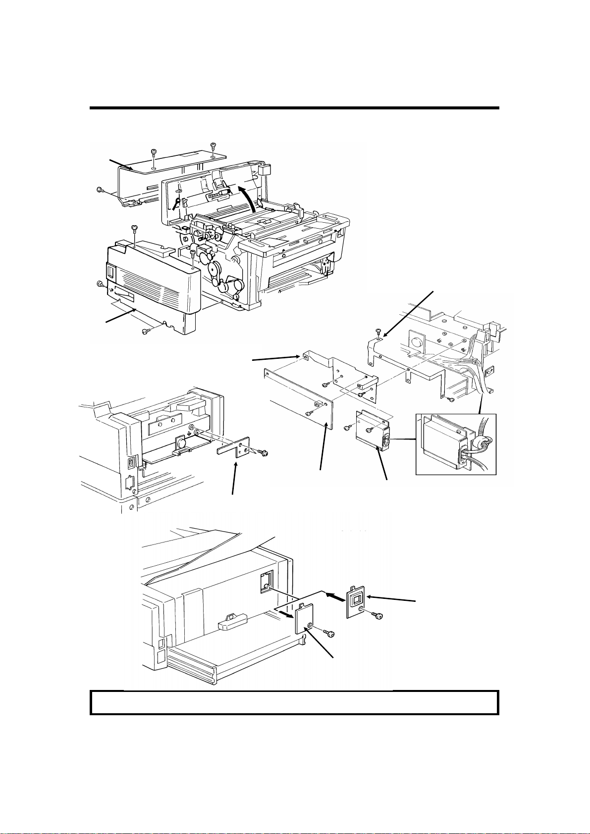
INSTALLATION PROCEDURE
1. INSTALLA TION
1.1. INSTALLATION PROCEDURE
Remove
the NCU before attach-
[D]
ing [D].
[C]
[E]
[G]
[F]
Component [F]: Europe only
[H]
Caution: Do not plug in or switch on until everything is connected up.
1-1
Page 5

19th August, 1992 INSTALLATION
FACTORY SETTINGS
1.2. FACTORY SETTINGS
The following tables show how to program the G4 Inte rna l Bit Swit che s (Fu nction 01) and G4 Paramet er Switches (Function 02) for each country. Make
sure that these values are correct at installation.
USA
Bit Switches All at 00 (H), except: Switch 00: 11(H)
Switch 14: 01(H)
Switch 19: 01(H)
Parameter Switches
SW 00 SW 01 SW 02 SW 03 SW 04 SW 05 SW 06 SW 07
00(H) 00(H) 00(H) 00(H) 07(H) 02(H) 00(H) 0B(H)
SW 08 SW 09 SW 0A SW 0B SW 0C SW 0D SW 0E
07(H) 00(H) 01(H) 0 B(H) 01(H) 00(H) B2(H)
Europe
Bit SwitchesAll at 00 (H), except : Switch 00: 02(H)
Switch 10: 01(H)
Switch 13: 04 (H) [Sweden]
Switch 14: 01 (H) [UK]
Switch 15: 40 (H) [France, Germany]
Parameter Switches
SW 00 SW 01 SW 02 SW 03 SW 04 SW 05 SW 06 SW 07
00(H) 01(H) 00(H) 00(H) 07(H) 02(H) 00(H) 0B(H)
SW 08 SW 09 SW 0A SW 0B SW 0C SW 0D SW 0E
07(H) 00(H) 01(H) 0B(H) 01(H) 00(H) B2(H)
Asia
Bit Switches All at 00 (H), except: Switch 00: 12(H)
Parameter Switches
SW 00 SW 01 SW 02 SW 03 SW 04 SW 05 SW 06 SW 07
00(H) 01(H) 00(H) 00(H) 07(H) 02(H) 00(H) 0B(H)
SW 08 SW 09 SW 0A SW 0B SW 0C SW 0D SW 0E
07(H) 00(H) 01(H) 0B(H) 01(H) 00(H) B2(H)
1-2
Page 6
19th June, 1993 SERVICE TABLES AND PROCEDURES
SERVICE LEVEL FUNCTIONS
2. SERVICE TABLES AND PROCEDURES
2.1. SERVICE LEVEL FUNCTIONS
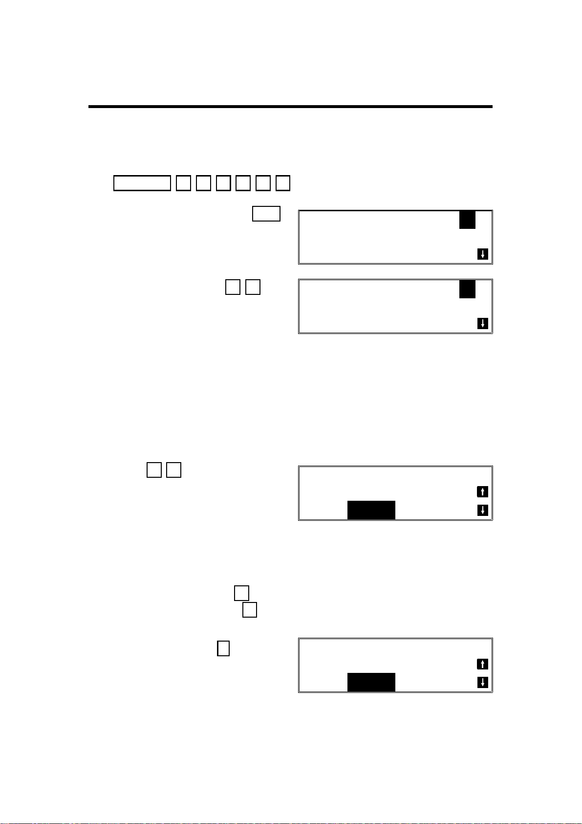
To enter G4 service mode, press the follo wing sequence of keys:
Function 6 0 1 9 9 1
then immediately Yes
Then press 1 8
SERVICE FUNCTION NO. _
01BIT SW. 02PARA LIST
03ERROR CODE 04SVC MONITOR
G4 NO. _
01 G4_ISW 02 G4_PSW
03 DN_IP 04 ISDN_IP
After completing a G4 service mo de operation, you must reset the machine
by switching it off, waiting for a few minutes, th en switching back on. THere is
no need to do this for any of the G3 service modes.
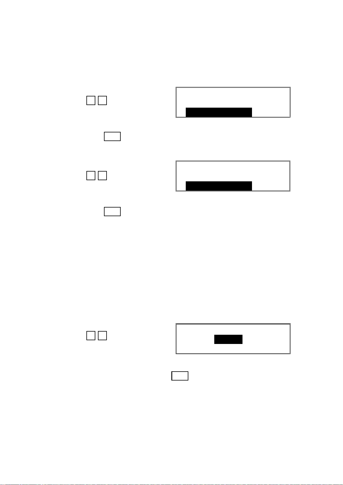
2.1.1. G4 Internal Switch Programming (Function 01)
1. After entering G4 service mode,
press 0 1
G4_ISW
DF: 00000000
SW:00 00000000
Bit 7 is displayed at the left , an d bit 0 at the right. The de fault settings are
shown on the top line, and the current settings on the bottom.
2. • Increment bit switch: ↓
• Decrement bit switch: ↑
Example:
Display bit switch 3: ↓ x 3
G4_ISW
DF: 00000000
SW:03 00000000
2-1
Page 7
SERVICE TABLES AND PROCEDURES 19th June, 1993
SERVICE LEVEL FUNCTIONS
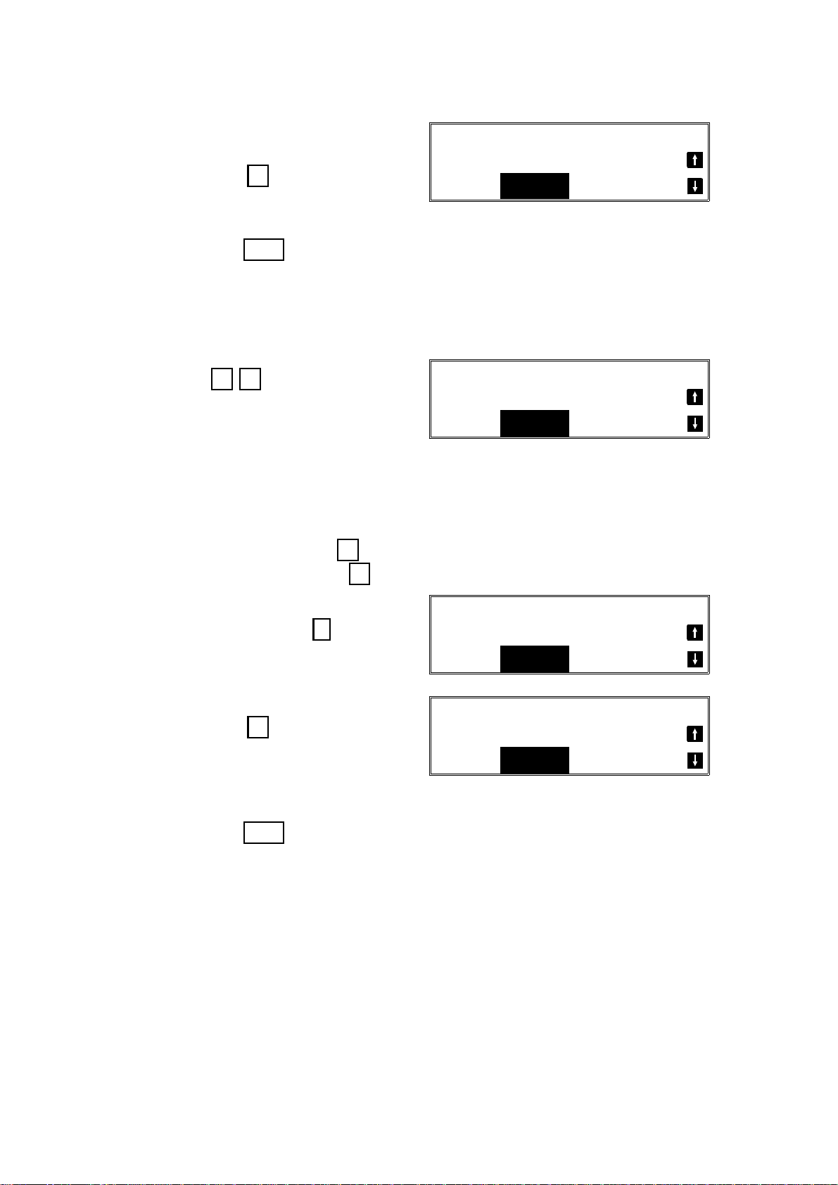
3. Adjust the bit switch.
Example: To change the value of
bit 7, press 7
G4_ISW
DF: 00000000
SW:03 10000000
4. Either:
• Adjust more bit switches - go to step 2.
• Finish - Yes
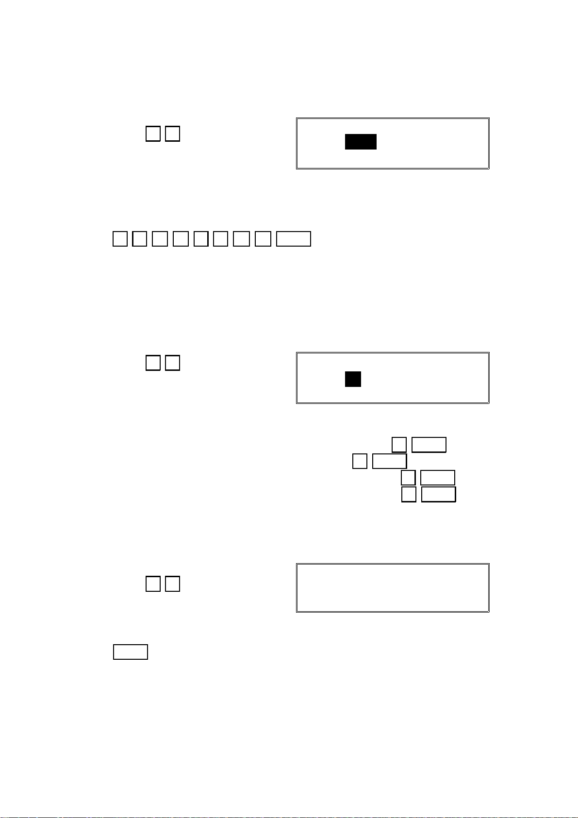
2.1.2. G4 Parameter Switch Programming (Function 02)
1. After entering G4 service mode,
press 0 2
G4_PSW
DF: 00000000
SW:00 00000000
Bit 7 is displayed at the left , an d bit 0 at the right. The de fault settings are
shown on the top line, and the current settings on the bottom.
2. • Increment bit switch: ↓
• Decrement bit switch: ↑
Example:
Display bit switch 3: ↓ x 3
3. Adjust the bit switch.
Example: To change the value of
bit 7, press 7
4. Either:
• Adjust more bit switches - go to step 2.
• Finish - Yes
2.1.3. Storing the DNIP (Function 03)
Do not use this function.
G4_PSW
DF: 00000000
SW:03 00000000
G4_PSW
DF: 00000000
SW:03 10000000
2-2
Page 8
19th June, 1993 SERVICE TABLES AND PROCEDURES
SERVICE LEVEL FUNCTIONS
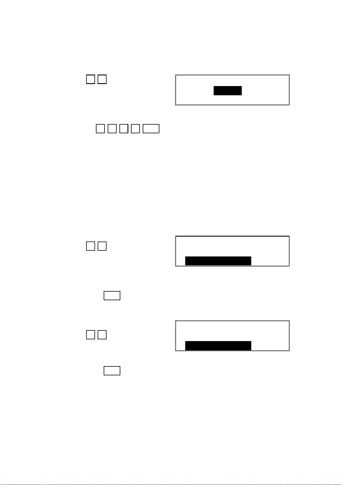
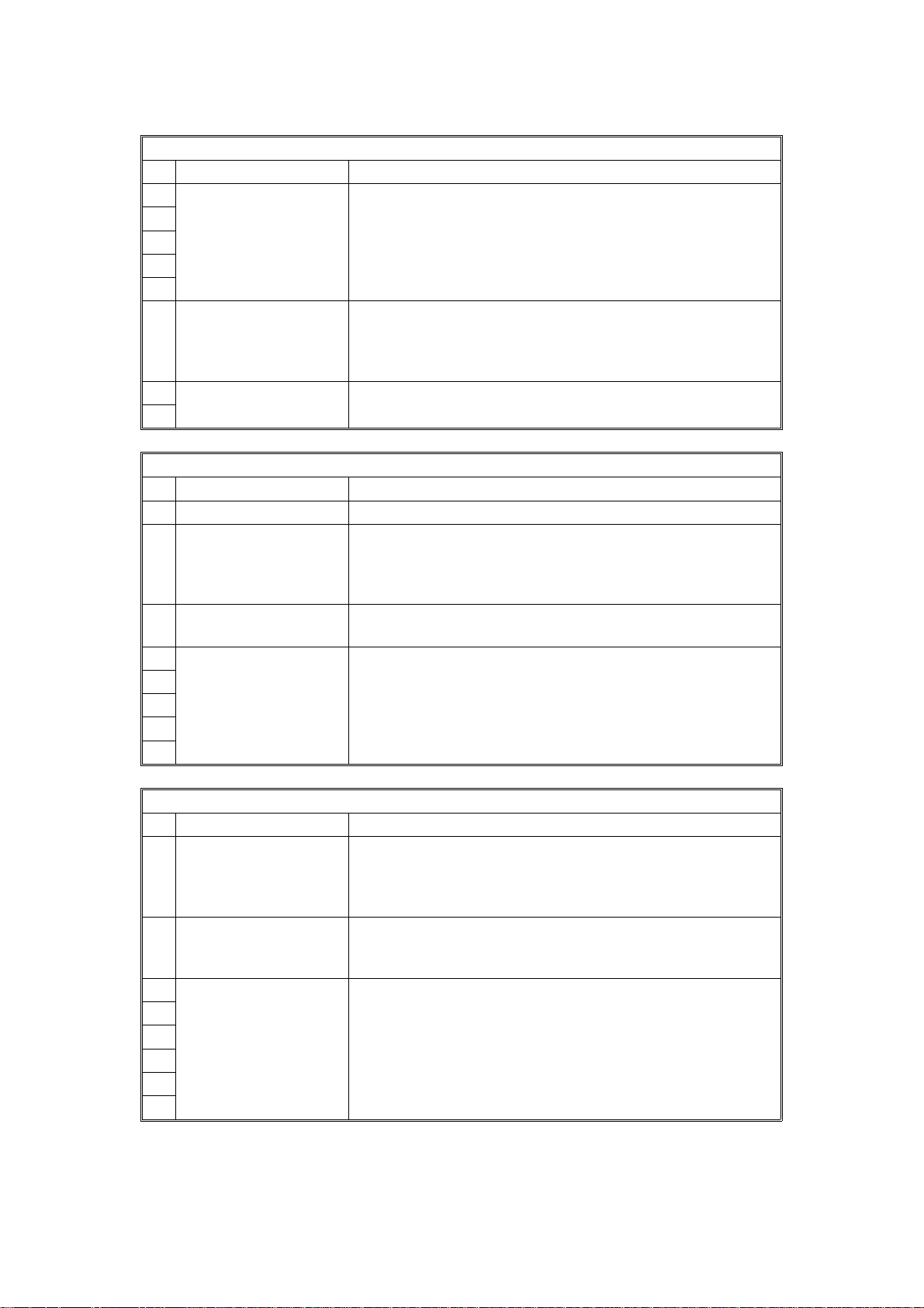
2.1.4. Storing the ISDN-IP (Function 04)
1. After entering G4 service mode,
press 0 4
ISDN_IP
2. Input the ISDN International Prefix (ISDN-IP).
Example: 1 2 3 4 Yes
2.1.5. Storing the Firs t G4 Subs cr ibe r Numbe r (Function 05)
Program the Second Subscriber Numb er when you have two units connected
to the same line. Program the number of the other unit as the Second Subscriber Number. When a call comes in, if the other unit is busy, your machine
will answer the call. Also, note the following:
• When calling, the first subscriber numbe r will be added to th e Setup signal
as the Calling ID.
• When receiving, the Called ID will be compared with the first and second
subscriber numbers.
1. After entering G4 service mode,
G4_SN1
press 0 5
2. Input the number. Include a pause at the start of the n umber.
Then press Yes
2.1.6. Storing the Second G4 Subs cr ibe r Numbe r (Function 06)
1. After entering G4 service mode,
G4_SN2
press 0 6
2. Input the number. Include a pause at the start of the n umber.
Then press Yes
2-3
Page 9
SERVICE TABLES AND PROCEDURES 19th June, 1993
SERVICE LEVEL FUNCTIONS
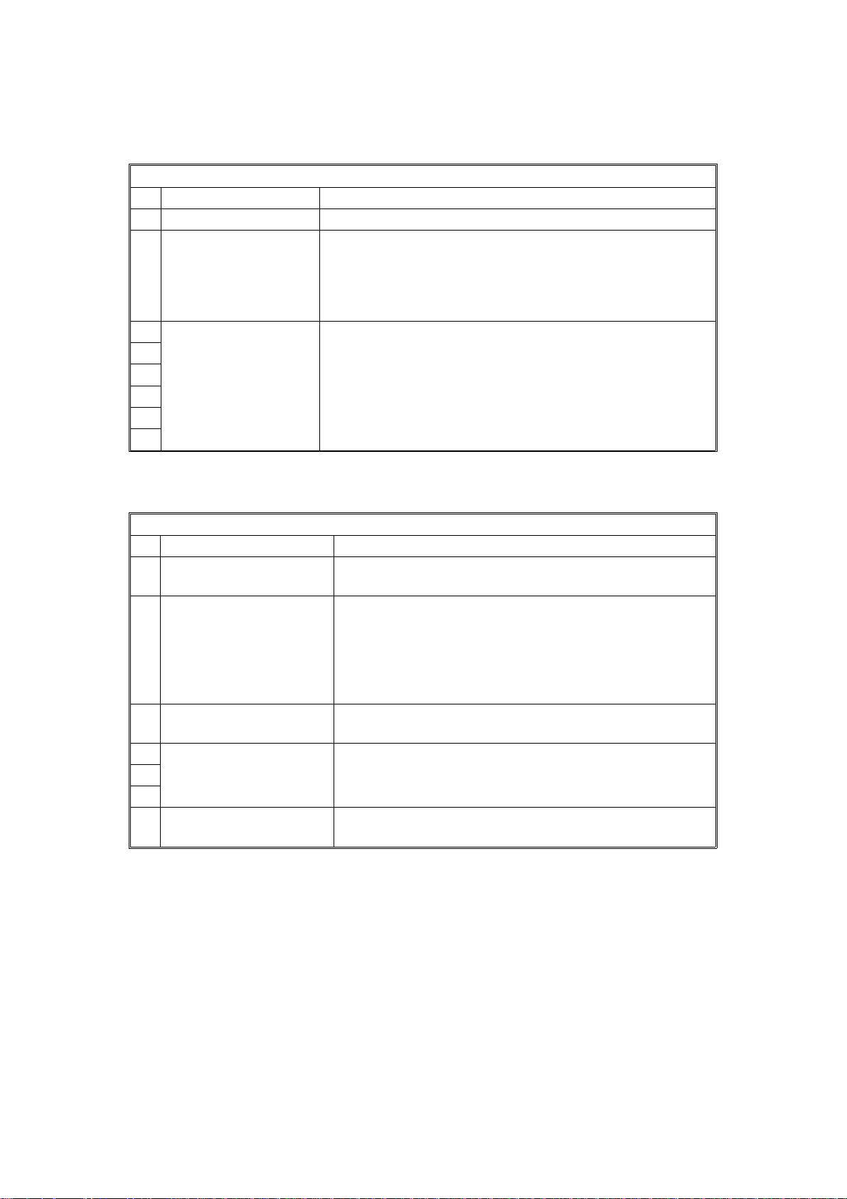
2.1.7. Storing the First ISDN G3 Subscriber Number (Function 07)
The function of th is is similar to the G4 Su bscrib er Number, except that it operates for G3 communicatio ns on the IDSN.
1. After entering G4 service mode,
IG3_SN1
press 0 7
2. Input the number. Include a pause at the start of the n umber.
Then press Yes
2.1.8. Storing the Second ISDN G3 Subscriber Number (Function 08)
1. After entering G4 service mode,
IG3_SN2
press 0 8
2. Input the number. Include a pause at the start of the n umber.
Then press Yes
2.1.9. Storing the ISDN Ac cess Unit No 1 (Function 09)
This is only for use during PTT ap pro val te sts.
2.1.10. Storing the ISDN Access Unit No 2 (Function 10)
Do not use this function
2.1.11. Storing the G4 Subaddress (Function 11)
1. After entering G4 service mode,
G4_SA
press 1 1
2. Input the subaddress. Then press Yes
2-4
Page 10

19th June, 1993 SERVICE TABLES AND PROCEDURES
SERVICE LEVEL FUNCTIONS
2.1.12. Storing the ISDN G3 Subaddress (Function 12)
1. After entering G4 service mode,
IG3_SA
press 1 2
2. Input the subaddress. Then press Yes
2.1.13. Storing the G4 Termi nal ID (Func tion 13)
1. After entering G4 service mode,
G4_TID
press 1 3
-=
2. First, input the ISDN’s country
code.
For example: 1 2 3 4 Yes
3. Input the machine’s telephone num-
G4_TID
1234-=
-
G4_TID
ber , then press Yes
1234-5551234=
= ABC
4. Input the G4 terminal name.
G4_TID
= XYZ CO. NEW YORK ABC
5. Press Yes
2.1.14. Storing the ISDN G3 CSI (Function 14)
1. After entering G4 service mode,
press 1 4
IG3_CSI
2. Input the CSI. Then press Yes
2-5
1234-5551234=
YES OR CLR . NO
YES
TO END
Page 11
SERVICE TABLES AND PROCEDURES 19th June, 1993
SERVICE LEVEL FUNCTIONS
2.1.15. Printing a G4 Memory Dump (Function 15)
1. After entering G4 service mode,
press 1 5
G4 MEMORY DUMP
ADD. H - ADD. FFH
2. Input the range of addresses that you wish to print.
Example: Addresses 22AA00 to 22BBFF
2 2 A A 2 2 B B Start
2.1.16. Printing a G4 Protocol Dump List (Function 16)
1. After entering G4 service mo de , set parameter switch E bit 1 to 1 (use G4
function 02). Then make a test communication.
2. From the G4 service mode menu,
press 1 6
G4_DMP2
0 D+Bch1
PRESS START
3. Either:
• Print a protocol dump list for the B and D channels: 0 Start
• Print a protocol dump list for the D channel: 1 Start
• Print a protocol dump list for the B channel link layer: 2 Start
• Print a protocol dump list for the D channel link laye r: 3 Start
4. Reset parameter switch E bit 0 to 0 after you have finished.
2.1.17. Printing the G4 System Parameter List (Function 17)
1. After entering G4 service mode,
press 1 7
G4 SYSTEM PARAMETER LIST
PRESS START
2. Start
2.1.18. Modem/DTMF Tone Tests (Function 18)
This is only for use during PTT ap pro val te sts.
2-6
Page 12

19th June, 1993 SERVICE TABLES AND PROCEDURES
BIT SWITCHES
2.2. BIT SWITCHES
WARNING
Do not adjust a bit switch that is described as "Not used", as this
may cause the machine to malfunction or to operate in a manner
that is not accepted by local regulations. Such bits are for use only
in other areas, such as Japan.
2.2.1. G4 Internal Switches
Bit Switch 00
FUNCTION COMMENTS
0
Country code
1
Bit 4 3 2 1 0 Country Bit 4 3 2 1 0 Country
0 0 0 0 0 France 0 1 1 0 1 Holland
2
0 0 0 0 1 Germany 0 1 1 1 0 Spain
0 0 0 1 0 UK 0 1 1 1 1 Israel
3
0 0 0 1 1 Italy 1 0 0 0 1 USA
0 0 1 0 0 Austria 1 0 0 1 0 Asia
4
0 0 1 0 1 Belgium 1 0 0 1 1 Japan
0 0 1 1 0 Denmark 1 0 1 0 0 Hong Kong
5
0 0 1 1 1 Finland 1 0 1 0 1 South Africa
0 1 0 0 0 Ireland 1 0 1 1 0 Australia
6
0 1 0 0 1 Norway 1 0 1 1 1 New Zealand
0 1 0 1 0 Sweden 1 1 0 0 0 Singapore
7
0 1 0 1 1 Switzerland 1 1 0 0 1 Malaysia
0 1 1 0 0 Portugal
Bit switches 01 an d 02 are not used.
Bit Switch 03
FUNCTION COMMENTS
0 Frame save area
status after each
communication
0: Erased 1: Kept
1 Not used Do not change the factory settings.
2
3
4
5
6
7
If you wish to keep the protocol frames of communications
in the memory buffer, set this bit to 1. The buffer can record
several communications
2-7
Page 13
SERVICE TABLES AND PROCEDURES 19th June, 1993
BIT SWITCHES
Bit Switch 04
FUNCTION COMMENTS
0 Not used Do not change the factory settings.
1
2
3
4
5 RCBCTR
0: Not valid 1: Valid
6 Not used Do not change the factory settings.
7
Bit Switch 05
FUNCTION COMMENTS
0 Not used Do not change the factory setting.
1 Logical channel
number (LCN)
0: Not controlled
1: Fixed at 01
2 Protocol ID check
0: Yes 1: No
3 Not used Do not change the factory settings.
4
5
6
7
This bit is used in Germany; set it to 1 for German PTT
approval tests.
1: RCBCTR counts consecutive R:RNR. If the counter
reaches the value of N2, the link is disconnected.
This bit is normally 0. However, some networks may require
a fixed LCN. In such cases, this bit should be 1, and you
may have to set a different value for the LCN using G4
Parameter Switch A.
The Protocol ID is in the CR packet.
Bit Switch 06
FUNCTION COMMENTS
0 Inclusion of the DTE
address in the S:CR
packet
0: No 1: Yes
1 Calling and called
DTE addresses
0: Not used 1: Used
2 Not used Do not change the factory setting.
3
4
5
6
7
When the CR packet format matches IS8208 protocol, some
networks may require this bit to be set at 1.
This bit is only effective if bit 0 of G4 Parameter switch 6 is
at 1.
This is only for packet networks. The CR packet should
contain the rx side’s DTE address, but does not have to
include the tx side’s; it can include it as an option.
2-8
Page 14
19th June, 1993 SERVICE TABLES AND PROCEDURES
BIT SWITCHES
Bit switch 07 and 08 are not used.
Bit Switch 09
FUNCTION COMMENTS
0 Not used Do not change the factory setting.
1 New session within
the same call
0: Not accepted
1: Accepted
2 Not used Do not change the factory settings.
3
4
5
6
7
0: If a new R:CSS is received, the machine sends back
S:RSSN.
1: If a new R:CSS is received, the machine sends back
S:RSSP.
Set this bit to 1 for German PTT approval tests.
Bit switches 0A to 0F are not used.
Bit Switch 10
FUNCTION COMMENTS
0 Connection detector
0: Disabled 1: Enabled
12Layer 1 T3 timer
Bit 2 1 Time
0 0 5 s
0 1 29 s
1 0 10 s
1 1 Not used
3 Layer 1 T4 timer
0: Not used 1: Used
4 Not used Do not change the factory settings.
5
6
7 Loop back 4 mode
0: Disabled 1: Enabled
0: USA and Japan
1: Europe
This should be kept at 5 s (both bits at 0) for normal
operation. However, you may have to change this during
PTT approval tests.
Set this bit to 1 for French PTT approval tests.
This is normally kept at 0. However, set it to 1 for British
PTT approval tests.
2-9
Page 15

SERVICE TABLES AND PROCEDURES 19th June, 1993
BIT SWITCHES
Bit Switch 11
FUNCTION COMMENTS
0 Action in reply to a link
release request
0: Link is released
1: Link is not released
1 T ype of TEI used
0: Dynamic TEI
1: Static TEI
2 Static TEI value This is used in the USA with the DMS100 (Northern Telecom
3
4
5
6
7
Do not change the factory setting.
This is normally fixed at 0. However, some networks such as
the Northern Telecom ISDN may require this bit to be set at
1 (see below). In this case, you may have to change the
values of bits 2 to 7.
ISDN) exchanger.
Store the low bit of the TEI at bit 7 and the high bit of the
TEI at bit 2.
Example: If the static TEI is 011000, set bits 3 and 4 to 1
and bits 2, 5, 6, and 7 to 0.
Bit switch 12 is not used. Do not change any of th e facto ry se tt ing s.
Bit Switch 13: D channel layer 3 (Attachment IE in S: SETUP)
FUNCTION COMMENTS
0 Not used Do not change the factory settings.
1
2 Attachment of calling
ID
0: No 1: Yes
3 Attachment of the
Lower Layer
Capabilities
0: No 1: Yes
4 Attachment of the
Higher Layer
Capabilities
0: Yes 1: No
5 Not used Do not change the factory settings.
6
7
Normally, this bit should be at 0. However, some networks
may require this ID, and in these cases, this bit should be at
1.
This bit determines whether Lower Layer Capabilities are
informed in the [Setup] signal or not.
This bit determines whether Higher Layer Capabilities are
informed in the [Setup] signal or not.
2-10
Page 16

19th June, 1993 SERVICE TABLES AND PROCEDURES
BIT SWITCHES
Bit Switch 14: D channel layer 3 (Selection IE in S: SETUP)
FUNCTION COMMENTS
0 G3 calling mode
0: 3.1 kHz audio
1: Speech
1 Not used Do not change the factory settings.
2
34Channel selection in
[SETUP] in tx mode
Bit 4 3 Setting
0 0 Any channel
0 1 B1 channel
1 0 B2 channel
1 1 Not used
5 Called ID mapping
0: Called party number
1: Keypad facility
6 Numbering plan for the
called party number
0: Unknown
1: E.164
7 Subaddress
0: IA5 1: BCD
This determines the bearer capability informed in the
[Setup] message. Set this bit to 1 if the ISDN does not
support 3.1 kHz audio. This bit is only used in the USA
and the UK.
Any channel: When this is informed to the exchanger,
the exchanger will select either B1 or B2.
0: Called ID is mapped to the called party number.
1: Called ID is mapped to the keypad facility.
On the 5ESS network (USA), set it to 1.
E.164: This may be used in Sweden if the AXE10
exchanger is fitted with old software.
Unknown: This is the normal setting.
This is normally kept at 0. However, some networks
require this bit to be at 1.
Bit Switch 15: D channel layer 3 (Judgement R: MSG)
FUNCTION COMMENTS
0 Action when receiving
[Setup] containing no
called subaddress, if
the subaddress was
programmed in the
dialed number
0: A reply is sent
1: No reply is sent
1 Not used Do not change the factory settings
2
3
4
5 Global call reference
0: Ignored
1: Global call number
is used
6 Not used Do not change the factory settings.
7
This bit depends on user requirements. If it is at 1,
communication will be halted if the other terminal has not
input their subaddress value.
Global call reference means ’call reference value = 0’. This
bit determines how to deal with such an incoming call if
received from the network.
Keep this bit at 1 in France and Germany.
2-11
Page 17

SERVICE TABLES AND PROCEDURES 19th June, 1993
BIT SWITCHES
Bit Switch 16: D channel layer 3 (Approval)
FUNCTION COMMENTS
0 Not used Do not change the factory settings.
1
2
3
4
5 Indicated bearer
capabilities
0: 56 k 1: 64 k
6 Not used Do not change the factory settings.
7
Bit Switch 17: Fallback from ISDN G4 to ISDN G3
FUNCTION COMMENTS
0 Condition for fallback from G4 to G3
Bits 0 to 6 of bit switch 17 contain a CPS code, and bits 0 to 6 of bit switch 18 contain
1
another CPS code. If a CPS code is received which is the same as either of these,
2
communication will fall back from ISDN G4 mode to ISDN G3 mode.
3
The CPS codes must be the same as those specified in table 4-13 of CCITT
4
recommendation Q.931.
Examples: Bit 6 5 4 3 2 1 0
5
6
This feature may not be available in Germany; this is not decided yet.
For the codes in bits 0 to 6 of bit switches 17 and 18 to be recognized, bit 7 of bit
switch 17 must be 1. Also, bit 0 of RAM address 00015C (Service Switch 1C) must be
at 0, or Fallback from G4 to G3 will be disabled.
1 0 0 0 0 0 1 CPS code 65
1 0 1 1 0 0 0 CPS code 88
1: 64 k calling is indicated in the Bearer Capabilities, but
communication is at 56 k.
7 This bit determines whether fallback from G4 to G3 occurs on receipt of one of the
CPS codes programmed in bit switch 17 or 18, or on receipt of a certain standard
code.
0: Fallback occurs on receipt of the following CPS codes. UK: 3, 63, 65, or 88,
Germany: 53, Other areas: 3, 65, or 88
1: Fallback from G4 to G3 occurs on receipt of one of the CPS codes programmed in
bit switch 17 or 18
2-12
Page 18

19th June, 1993 SERVICE TABLES AND PROCEDURES
BIT SWITCHES
Bit Switch 18: Fallback from ISDN G4 to ISDN G3
FUNCTION COMMENTS
0 Condition for fallback from G4 to G3
See the explanation for bits 0 to 6 of bit switch 17
1
2
3
4
5
6
7 Not used Do not change the factory setting.
Bit Switch 19
FUNCTION COMMENTS
0 Permanence of the link
0: Set/released each
LAPD call
1: Permanent
1 Channel used in ISDN
L2 (64k) mode
0: B1 1: B2
2 Not used Do not change the factory settings.
3
4
5
6
7
Keep this at 1 in the USA. In other areas, this bit is normally
0, depending on network requirements.
When making an IDSN L2 back-to-back test, you can select
either the B1 or B2 channel with this bit switch.
Bit switches 1A to 1F are not used. Do not change any of the factory settings.
2-13
Page 19

SERVICE TABLES AND PROCEDURES 19th June, 1993
BIT SWITCHES
2.2.2. G4 Parameter Switches
Parameter Switch 0
FUNCTION COMMENTS
0 Network type
Bit 2 1 0 Type
1
x 0 0 Circuit switched ISDN
2
Other settings: Not used
3 Not used Do not change the factory settings.
4
5
6
7
Parameter Switch 1
FUNCTION COMMENTS
0 Voice coding
0: µ law
1: A law
1 Not used Do not change the factory settings.
2
3
4
5
6
7
0: This setting is used in Japan, Taiwan, and the USA.
1: This setting is used in Europe and Asia.
Parameter Switch 2
FUNCTION COMMENTS
01Data rate (kbps)
Bit 1 0 Setting
0 0 64 kbps
0 1 56 kbps
2 Not used Do not change the factory settings.
3
45Transmission mode
Bit 5 4 Mode
0 0 CS
6 Not used Do not change the factory settings.
7
Other settings: Not used
Other settings: Not used
2-14
Page 20

19th June, 1993 SERVICE TABLES AND PROCEDURES
BIT SWITCHES
Parameter Switch 3
FUNCTION COMMENTS
0 Link modulus
0: 8 1: 128
1 Not used Do not change the factory settings.
2
3
4
5
6
7
This setting determines whether protocol frame numbering
is done using 3 bits (0 to 7 then start again at 0) or 7 bits (0
to 127 then start again at 0). Set this bit switch to match the
network’s specifications.
Parameter Switch 4 is not used. Do no t cha ng e any of th e facto ry se tt ing s.
Parameter Switch 5
FUNCTION COMMENTS
Link timer
0
Bit 3 2 1 0 Value
1
0 0 0 0 0
0 0 0 1 1
2
0 0 1 0 2
and so on until
3
1 0 1 0 10
4 Not used Do not change the factory settings.
5
6
7
The link timer is the maximum allowable time between
sending a protocol frame and receiving a response frame
from the remote terminal.
Parameter Switch 6
FUNCTION COMMENTS
0 Layer 3 protocol
0: ISO8208
1: T.70NULL
1 Not used Do not change the factory settings.
2
3
4 Packet modulus
0: 8 1: 128
5 Not used Do not change the factory settings.
6
7
Set this bit to match the type of layer 3 signalling used by
the ISDN.
Do not change the factory setting, unless the machine is
experiencing compatibility problems.
2-15
Page 21

SERVICE TABLES AND PROCEDURES 19th June, 1993
BIT SWITCHES
Parameter Switch 7
FUNCTION COMMENTS
Packet size
0
Bit 3 2 1 0 Value
1
0 1 1 1 128
1 0 0 0 256
2
1 0 0 1 512
1 0 1 0 1024
3
1 0 1 1 2048
4 Not used Do not change the factory settings.
5
6
7
Parameter Switch 8
FUNCTION COMMENTS
Packet window size
0
Bit 3 2 1 0 Value
1
0 0 0 1 1
0 0 1 0 2
2
and so on until
1 1 1 1 15
3
4 Not used Do not change the factory settings.
5
6
7
This value is sent in the CR packet. This value must match
the value stored in the other terminal, or communication will
stop (CI will be returned). If the other end returns CI, check
the value of the packet window size with the other party.
Note that this value must be the same as the value
programmed for the transport block size (G4 Parameter
Switch B, bits 0 to 3).
This is the maximum number of unacknowledged packets
that the machine can send out before having to pause and
wait for an acknowledgement from the other end.
This should be kept at 7 normally.
If the packet modulus (G4 Parameter Switch 6, bit 4) is 8,
the packet window size cannot be more than 7. However, if
the packet modulus is 128, the window size can be up to 15.
Also, if the layer 3 protocol setting (G4 Parameter Switch 6,
bit 0) is at IS8208, the packet window size cannot be more
than 7.
Parameter Switch 9
FUNCTION COMMENTS
LCGN
0
Bit 3 2 1 0 Value
1
0 0 0 0 0
0 0 0 1 1
2
0 0 1 0 2
and so on until
3
1 1 1 1 15
Keep the value of the LCGN at 0.
2-16
Page 22

19th June, 1993 SERVICE TABLES AND PROCEDURES
BIT SWITCHES
Parameter Switch 9
FUNCTION COMMENTS
4 Not used Do not change the factory settings.
5
6
7
Parameter Switch A
FUNCTION COMMENTS
0
LCN
1
Bit 7 6 5 4 3 2 1 0 Value
2
0 0 0 0 0 0 0 1 1
3
0 0 0 0 0 0 1 0 2
4
0 0 0 0 0 0 1 1 3
5
and so on until
6
1 1 1 1 1 1 1 1 255
7
Parameter Switch B
FUNCTION COMMENTS
Transport block size
0
Bit 3 2 1 0 Value
1
0 1 1 1 128
1 0 0 0 256
2
1 0 0 1 512
1 0 1 0 1024
3
1 0 1 1 2048
4 Not used Do not change the factory settings.
5
6
7
This value must match the value set in the other terminal.
Note that this value must be the same as the value
programmed for the packet size (G4 Parameter Switch 7,
bits 0 to 3). Also, the transport block size is limited by the
amount of memory in the remote terminal.
Keep at the value of the LCN at 1.
Parameter Switch C is not used. Do not chan ge any of the factory settings.
Parameter Switch D
FUNCTION COMMENTS
01Back-to-back test mode
Bit 1 0 Setting
0 0 Off
0 1 Not used
1 0 ISDN L2 test mode (TE mode)
1 1 ISDN L2 test mode (NT mode)
When doing a back-to-back test, use
these bits to set up one of the machines
in TE mode, and the other in NT mode.
After the test, return both bits to 0.
2-17
Page 23

SERVICE TABLES AND PROCEDURES 19th June, 1993
BIT SWITCHES
Parameter Switch D
FUNCTION COMMENTS
2 Not used Do not change the factory settings.
3
4
5
6
7
2-18
Page 24

19th June, 1993 SERVICE TABLES AND PROCEDURES
BIT SWITCHES
Parameter Switch E
FUNCTION COMMENTS
0 Debug mode - real
time display
0: Off 1: On
1 Debug mode - C/R
frame save
0: Off 1: On
2 Not used Do not change the factory settings.
3
4
5
6
7
If this is switched on, a status code will be displayed in the
bottom right corner of the LCD. These codes are explained
in the Troubleshooting section.
Set this bit to 1 when you wish to print a protocol dump list.
Set it back to 0 after printing.
2-19
Page 25

SERVICE TABLES AND PROCEDURES 19th June, 1993
DEDICATED TRANSMISSION PARAMETERS
2.3. DEDICATED TRANSMISSION PARAMETERS
The following G4 communication para met er bytes have been added for each
Quick Dial and Speed Dial. For how to program Ded icat ed Transmission Parameters, refer to th e Se rvice Manual for the base machine .
Bytes 1 to 4 are for use with Group 3 commun ication and are explained in the
Service Manual for the base machine. Byte 5 is not used.
Byte 6
FUNCTION
0
Data rate Bit 3 2 1 0 Setting
1
2
3
4 Not used
5
6
7
0 0 0 0 64 kbps
0 0 0 1 56 kbps
1 1 1 1 As in Parameter Switch 2, bits 0 and 1
Other settings: Not used
Byte 7
0
Link modulus Bit 3 2 1 0 Setting
1
2
3
4 Not used
5
6
7
Byte 8
0
Layer 3 protocol Bit 3 2 1 0 Setting
1
2
3
4
Packet modulus Bit 3 2 1 0 Setting
5
6
7
0 0 0 0 Modulo 8
0 0 0 1 Modulo 128
1 1 1 1 As in Parameter Switch 3, bit 0
Other settings: Not used
0 0 0 0 IS.8208
0 0 0 1 T.70 NULL
1 1 1 1 As in Parameter Switch 6, bit 0
Other settings: Not used
0 0 0 0 Modulo 8
0 0 0 1 Modulo 128
1 1 1 1 As in Parameter Switch 6, bit 4
Other settings: Not used
FUNCTION
FUNCTION
2-20
Page 26

19th June, 1993 TROUBLESHOOTING
ERROR CODES
3. TROUBLESHOOTING
3.1. ERROR CODES
The following error codes will be printed on the Service Monitor Report. See
the Service Manual for the base machin e fo r in stru ctions on how to print this
report.
The meaning of the numbers in the A ctio n co lumn is as follows.
1. Check Layer 1 signalling with a protocol analyzer to determine th e cau se
of the problem. This may require assistance from a G4 specialist.
2. Repeat the communication. If the prob lem does no t rep ea t itse lf, the prob lem was a temporary one caused by t he user connecting the machine to
another interface. Howeve r, if the problem remains, there is a network
problem.
3. There is a network problem.
4. There is a network problem. Do th e f ollo wing:
• Check the error bit rate of the network. If it is high, cont act the network
and ask them to improve the line.
• Check the network speed (is it 56 or 64 kbps), and make sure th at the
bit switch setting is correct. You may also use the dedicated transmission parameters if this proble m o nly occu rs when diallin g cert ain numbers.
• Check that the user diall e d the correct number.
5. There is a network problem, or a prob lem in th e machine at the other end.
6. There is a problem in the machin e at t he oth er en d; ask a technician to
check it.
7. The machine at the other end is not a G roup 4 fax terminal.
8. The machine is not compatible with the machine at the other e nd . A compatibility test is needed.
3-1
Page 27

TROUBLESHOOTING 19th June, 1993
ERROR CODES
3.1.1. D-channel, Layer 1
Code Probable Cause Action
7-00 T3 timeout (layer 1 activation error) 1
7-01 No connection on the S0 interface 1
7-02 Deactivated 1
3.1.2. D-channel Link Layer
Code Probable Cause Action
7-20 At the start of link set-up, the machine received an unsolicited S (F=1). 2
7-21
7-22 At TEI release, the machine received an unsolicited UA (F=1). 2
7-23
7-24 At TEI release, the machine received an unsolicited UA (F=0). 2
7-25 SABME received at the start of network link set-up No error
7-26 N200 retransmission error for SABME 2
7-27 N200 retransmission error for DISC 2
7-28 N200 retransmission error for situation enquiry (RR) 2
7-29 N(R) sequence number error 3
7-30 N(S) sequence number error 3
7-31 FRMR received 3
7-32 Non-standard frame received 3
7-33 Abnormal frame length 3
7-34 N201 error; information field N in the I frame exceeded N201 3
7-35 T201 timeout; timeout while waiting for checking 3
7-36 T202 timeout; timeout while waiting for ID assignment 3
At the start of link set-up, the machine received an unsolicited DM
(F=1).
At the start of link set-up, the machine received an unsolicited DM
(F=0).
2
2
3.1.3. D-channel Network Layer
Code Probable Cause Action
7-40 Insufficient mandatory information elements 3
7-41 Abnormal LI for a mandatory information element 3
7-42 T301 timeout; timeout while waiting for R:CONN 3
7-43 T303 timeout; timeout while waiting for R:CALL-PROC etc. 3
7-44 T304 timeout; timeout while waiting for R:CALL-PROC etc. 3
7-45 T305 timeout; timeout while waiting for R:REL 3
7-46 T308 timeout; timeout while waiting for R:REL-COMP 3
7-47 T310 timeout; timeout while waiting for R:ALERT etc. 3
7-48 T313 timeout; timeout while waiting for R:CONN-ACK 3
7-49 Internal error 3
7-51 Release call reference during communication 3
3-2
Page 28

19th June, 1993 TROUBLESHOOTING
ERROR CODES
3.1.4. B-channel Link Layer
Code Probable Cause Action
7-60 T3 timeout; timeout while waiting for flag 4
7-61 T3 timeout; timeout while waiting for SABM during an incoming call 4
7-62 T1 timeout x N2; timeout while waiting for UA after sending SABM 5
7-63
7-64
7-65 T1 timeout x N2; timeout while waiting for a response to DISC 5
7-66 RNR x N2 (other end busy, RCB counter error) 5
7-67 Invalid (Ad) frame received 5
7-68 Invalid short frame received 5
7-69 Link reset error 5
7-70 FRMR received 5
7-71 Non-standard (Cn) frame received 5
7-72 An S or U frame having an information field was received 5
7-73 A frame longer than the maximum N1 length was received 5
7-74 An S or I frame having an N(R) error was received 5
7-75 CRC error 3
T1 timeout x N2; timeout while waiting for a response to a transmitted
S frame (P=1)
T1 timeout x N2; timeout while waiting for SABM or DISC after
sending FRMR
5
5
3.1.5. B-channel Network Layer
Code Probable Cause Action
7-80 A packet having an abnormal GFI was received 6
7-81
7-82 A packet containing a format error was received 6
7-83 A packet containing an LI error was received 7
7-84 A CN packet was received that had a PID different from 02 7
7-85 Unsupported packet type received 7
7-86 Abnormal or unsupported facility received 7
7-87 P(s) sequence number error 6
7-88 P(r) sequence number error 6
7-89 A reset using S:RQ or R:RI occurred 6
7-90 A restart using S:RQ or R:SI occurred 6
7-91
7-92 T20 timeout; timeout while waiting for an SF packet 6
7-93 T21 timeout; timeout while waiting for a CC packet 6
7-94 T22 timeout; timeout while waiting for an RF packet 6
7-95 T23 timeout; timeout while waiting for a CF packet 6
7-96 T10 timeout; timeout while waiting for the first frame 6
A packet was received that had a logical channel number different
from the logical channel being used for the communication
Call set-up error; in reply to S:CR, R:CI was received to indicate
rejection of the call
6
7
3-3
Page 29

TROUBLESHOOTING 19th June, 1993
ERROR CODES
3.1.6. Transport Layer
Code Probable Cause Action
8-00 Invalid block received 8
8-01 TCC block received 8
8-02 TBR block received 8
8-05 TCR block; block format error 8
8-06 TCR block; block size parameter LI error 8
8-07 TCR block; extended addressing LI error 8
8-08 TCR block; block size length error 8
8-10 TCA block; block format error 8
8-11
8-12 TCA block; octet 7 did not equal 0 8
8-13 TCA block; extended addressing LI error 8
8-14 TCA block; block size exceeded that set by TCR 8
8-15 TCA block; block size parameter LI error 8
8-20 TDT block; block format error 8
8-21 TDT block; octet 3 did not equal either 00 or 80(H) 8
8-22
8-23
8-26 Timeout during state 0.2 8
8-27 Timeout during state 1.1 8
8-28 Timeout during state 0.3 8
TCA block; Tx origin reference data in TCR disagreed with the
address reference data in TCA
TDT block; the end indicator was "Continue" even though there was
no field data
TDT block; and end block with no field data was received after an end
indicator of "End"
8
8
8
3.1.7. Session Layer
Code Probable Cause Action
8-30 Invalid frame received 8
8-31 RSSN received 8
8-32 CSA received 8
8-34 Calling terminal identification error in CSS 8
8-35 Date and time error in CSS 8
8-36 Window size error in CSS 8
8-37 Service identification error in CSS 8
8-38 Session user data error in CSS 8
8-39 CSS rejected (new session rejected) 8
8-40 Called terminal identification error in RSSP 8
8-41 Date and time error in RSSP 8
8-42 Date and time in RSSP was not the same as that in CSS 8
8-43 Window size error in RSSP 8
8-44 Service identification error in RSSP 8
8-45 Ses sion user d ata er ror in RS SP 8
8-47 Message synchronization error inside the CCU 8
8-48 Document task busy 8
3-4
Page 30

19th June, 1993 TROUBLESHOOTING
ERROR CODES
Code Probable Cause Action
8-50 Ti timeout; non-communication surveillance timer (T.62) 8
8-51 T2 timeout; timeout while waiting for a response (T.62) 8
8-52 T3 timeout; CSA timer timeout (T.62) 8
8-53
8-54
8-55 G4 board load timer timeout; called side waited too long for S:RSSP 8
8-56
8-57
G4 board load timer timeout; calling side waited too long for a new
session
G4 board load timer timeout; calling side waited too long for transport
probability
G4 board load timer timeout; document transmission surveillance
timer timeout
G4 board load timer timeout; timeout while waiting for a user abort
request after a provider fail
8
8
8
8
3.1.8. Document Layer
Code Probable Cause Action
8-60 T.62 coding format error (LI error) 8
8-61 A mandatory PI was absent, or the LI for a mandatory PI was 0 8
8-62
8-63 The LI for session user data exceeded the maximum value (512) 8
8-64 The LI for CDUI was not 0 8
8-65
8-66 The checkpoint reference number differed from the expected value 8
8-70 RDGR received 8
8-71 A non-standard PDU was received while in calling mode 8
8-72 A non-standard PDU was received while in called mode 8
8-73 Abnormal PDU received while in calling state ds1 8
8-74 15 consecutive CDCL signals received 8
8-75 Session window size control error (size not equal to 0) 8
8-76 Internal error 8
Calling/called terminal identification LI was different from that
specified by F.184 (LI = 24)
Checkpoint and document reference numbers LI error, or they were
not in T.61 (ASCII) coding
8
8
3.1.9. Presentation Layer
Code Probable Cause Action
8-80 X.209 coding error in session user data (LI error) 8
8-81 PV error in session user data 8
8-82 PI error in session user data 8
8-83
8-84 X.209 coding error in the DP (LI error) 8
8-85
8-86 SLD object type absent 8
The capabilities in the session user data of CDS/CDC were not the
same as those in RDCLP
X.209 coding error in the SLD (document descriptor/page descriptor)
(LI error)
3-5
8
8
Page 31

TROUBLESHOOTING 19th June, 1993
ERROR CODES
Code Probable Cause Action
8-87 PI error in the SLD (document descriptor/page descriptor) 8
8-88
8-89 No document descriptor at the start of the document 8
8-90 No page descriptor at the start of the page 8
8-91 Page descriptor PV error 8
8-92 X.209 coding error in the TU (LI error) 8
8-93 The TU was absent 8
8-94 PV error in the TU 8
8-95 TI error 8
8-96 X.209 coding nest level > 8, or an LI form error 8
8-97
The capabilities in the SLD (document descriptor/page descriptor) are
duplicated or are not the same as those in RDCLP
CDPB/CDE received while TU/TI not yet completed, or an
unexpected PDU was received while analyzing an SLD
8
8
3.1.10. Hardware Errors
Code Meaning Suggested Cause/Action
3-00
3-10
3-11
3-20
3-21
3-30
CIG4 reset
The CIG4 did not send a response
to the FCU
Disconnection during ISDN G3
communication
Disconnection during ISDN G4
communication
A CSA signal was received during
ISDN G4 communication
A CSA signal was sent out after
the Stop key was pressed during
ISDN G4 communication
Mismatched specifications (rx
capabilities)
• Replace the CIG4 or the FCU.
• Check the ISDN line.
• Check the condition of the other terminal.
• Check the ISDN line.
• The other party accidentally dialled this
machine by mistake.
• Check the condition of the other terminal.
• Check the ISDN line.
• Check the condition of the other terminal.
• Check the ISDN line.
• The Stop key was pressed.
• Check the specifications of the other
terminal.
3-6
Page 32

19th June, 1993 TROUBLESHOOTING
G4CCU STATUS CODES
3.2. G4CCU STATUS CO DES
The display of G4CCU status code s is affected by the Real Time Display
On/off settin g (G4 Para meter Switch E, bit 0).
• If Real Time Display is off (the bit is 0; this is the default setting), there is
no indication on the operation panel.
• If Real Time Display is o n (the bit is 1), the codes are fully displaye d o n
the operation pane l.
The codes are defined in the followin g page s.
3.2.1. Layer 1 (Physical Layer)
Code (H) Status Code (H) Status
10 Ready E0 R: [DISC]
01 S: [SETUP] E1 S: [REL]
02 R: [CALL_PROC] E3 R: [REL_COMP]
03 R: [CONN] E4 R: [STAT ]
04 S: [CONN_ACK] E5 R: [STAT_ENQ]
05 R: [SETUP ACK] F0 S: [DISC]
06 R: [ALERT] F1 R: [REL]
11 R: [SETUP] F2 S: [REL_COMP]
12 S: [CALL_PROC] F3 S: [STAT]
13 S: [CONN]
14 R: [CONN_ACK]
3.2.2. Layer 2 (Link Layer)
Code (H) Status Code (H) Status
20 S: SABM, or R: SABM D0 S: DISC, or R: DISC
21 S: UA, or R: UA D1 S: DM, or R: DM
22 S: FRMR, or R: FRMR
28 S: SABME, or R: SABME
3-7
Page 33

TROUBLESHOOTING 19th June, 1993
G4CCU STATUS CODES
3.2.3. Network Layer (Layer 3)
Code (H) Status Code (H) Status
30 S: CR C2 S: SQ
31 R: CC C3 R: SF
38 R: CN CA R: SI
39 S: CA CB S: SF
32 S: GF C4 S: RQ
3A R: GQ C5 R: RF
3B R: GF CC R: RI
C0 S: CQ CD S: RF
C1 R: CF C6 R: IT
C8 R: CI C7 R: IF
C9 S: CF CE R: DIAG
3.2.4. Transport Layer (Layer 4)
Code (H) Status Code (H) Status
40 S: TCR, or R: TCR 42 S: TBR, or R: TBR
41 S: TCA, or R: TCA 43 S: TCC or R: TCC
3.2.5. Session Layer, Session Control Layer (Layer 5)
Code (H) Status Code (H) Status
50 S: CSS, or R: CSS 56 S: RSUI, or R: RSUI
51 S: RSSP, or R: RSSP A0 S: CSA, or R: CSA
52 S: RSSN, or R: RSSN A1 S: RSAP, or R: RSAP
53 S: CSCC, or R: CSCC A2 S: CSE, or R: CSE
54 S: RSCCP, or R: RSCCP A3 S: RSEP, or R: RSEP
3.2.6. Session Layer, Document Control Layer (Layer 5)
Code (H) Status Code (H) Status
60 S: CDCL, or R: CDCL 90 S: CDE, or R: CDE
61 S: RDCLP, or R: RDCLP 91 S: RDEP, or R: RDEP
62 S: CDS, or R: CDS 92 S: CDD, or R: CDD
63 S: CDC, or R: CDC 93 S: RDDP, or R: RDDP
64 S: CDPB, or R: CDPB 94 S: CDR, or R: CDR
65 S: RDPBP, or R: RDPBP 95 S: RDRP, or R: RDRP
70
S: CDUI, or R: CDUI (Data
phase - layer 6 and facsimile
data)
96 S: RDGR, or R: RDGR
97
S: RDPBN, or R: RDPBN
3-8
Page 34

19th June, 1993 TROUBLESHOOTING
G4CCU LED DISPLAY
3.3. G4CCU LED DISPLAY
There are six LEDs on the G4CCU board, as shown be low.
LED 5 LED 6
LED 1 LED 2 LED 3 LED 4
These LEDs give the following information about the status of the machine.
Initial Settings
Power-up/Reset O O
Initial setting request from FCU -- O
Initial setting confirmation to FCU -- --
O = ON, -- = OFF
-- -- -- --
-- -- -- --
-- -- -- --
Communication
Layer 1 activated -- --
O------
Layer 2 set -- --
OO----
B channel connected (ISDN G4) -- --
OOO--
B channel connected (ISDN G3) -- --
OO--O
B channel released -- --
OO----
Layer 2 released -- --
O------
Layer 1 deactivated -- --
-- -- -- -The following will be displayed if bit 1 of G4 parameter switch E is at 1.
B channel: send I frame (A blinks at this time if bit 1 of -- A
G4 parameter switch E is at 1) O O O --
B channel: receive I frame (B blinks at this time if bit 1 of B -G4 parameter switch E is at 1) O O O --
Note: At the start and end of communication, both A and B will blink.
3-9
Page 35

Both resistors
must be between
50 and 100 Ω.
TROUBLESHOOTING 19th June, 1993
BACK-TO-BACK TESTING
3.4. BACK-T O- BACK TES TI NG
To make a back-to-back test, you need:
• Two machines (they must be the same mo de l)
• Cross rosette
The procedure is as follows.
1. Switch off the machines
2. Connect two machines back-to-back using the cross rosette as follows.
1
2
3
4
5
6
7
8
Machine A
1
2
3
4
5
6
7
8
Cross Rosette
1
2
3
4
5
6
7
8
Machine B
3. Make the following bit switch adjustments:
• In the machine acting in NT mode, set bits 0 and 1 of G4 parameter
switch 0D to 1.
• In the machine acting in TE mo de , set bit 0 of G4 paramete r switch 0D
to 0 and bit 1 to 1.
4. Reset the machine by switching it off, waiting a few seconds, then switch-
5. Place a document in one of the machines, dial a number, then press St art.
6. After you have finishe d t he test, set bits 0 and 1 of G4 parameter swit ch
Note: The follo wing cannot be tested usin g th is p roce du re:
ing back on.
0D back to 0. then reset the mach ine .
• ISDN G3 communication
• P to M
3-10
 Loading...