

Page 1
RICOH FAX220/240
SERVICE MANUAL
Copyright © 1992, Ricoh Company Ltd., Japan
Subject to change
Page 2

1. INTRODUCTION
1-1. General Specifications
Item Specification
Type Desktop transceiver
Telephone Circuit PSTN/PBX
Document Size Width: 148 - 218 mm
Length: 105 - 600 mm
Thickness: 0.05 - 0.15 mm
Scanning Method Flat bed, CCD
Scanning Width 216 ± 1 mm
Effective Printing Width 210 mm (minimum)
Scan Resolution Standard: 8 x 3.85 dots/mm
Detail: 8 x 7.7 dots/mm
Fine: 8 x 15.4 dots/mm
Transmission Time FAX220 - 15 s (Measured using a CCITT #1 test chart,
Slerexe Letter, at 9,600 bps, MH coding with EFC,
10 ms/line I/O rate, standard resolution)
FAX240 - 11 s (Measured using a CCITT #1 test chart,
Slerexe Letter, at 9,600 bps, MMR coding with ECM, 10
ms/line I/O rate, standard resolution)
Data Compression Method MH, EFC, SSC, MR, MMR* (*: FAX240 only)
SAF Memory Capacity 128 kbytes (9 CCITT #1 test charts can be stored.)
Modulation Method V29, V27ter, V21
Transmission Data Rate 9600/7200/4800/2400 bps (Automatic fallback)
Protocol CCITT T.30 standard (NET 30)
Printing Method Thermal printing
Printer Paper Size 216 mm x 50 m roll
Dimensions 355 x 454 x 203 mm
Weight 4.6 kg
Input Voltage H501-50, 51, 52, 53, 54, H502-50, 51, 52, 53, 54:
220 - 240 Vac, 50 Hz single phase
H501-55, H502-55: 120 Vac, 50/60 Hz, single phase
Recommended Operating Environment Temperature: 17 - 28 °C
Humidity: 30 - 85 %RH
1-1
Page 3

1-2. Features LIst
Features FAX220 FAX240
Transmission
Automatic transmission yes yes
Manual transmission yes yes
ADF capacity 5 5
Automatic Contrast Control yes yes
Polling transmission yes yes
Send later yes yes
Dial via dialpad yes yes
Quick dial (one touch) 10 10
Speed dial (two touch) 40 40
Automatic redial yes yes
Manual redial yes yes
Label programming for Quick/Speed dials yes yes
Page indicator CSI + P.1 yes yes
Page indicator TTI + P.1 or P.1/10 yes yes
Automatic page retransmission in normal tx mode no yes
Reception
Automatic reception yes yes
Manual reception yes yes
Polled reception yes yes
Automatic cutter no yes
Manual cutter yes no
Authorized reception (with TSI) yes yes
Decurler no yes
Printing of the TSI on received copies yes yes
Communication
TTI (page header with name) yes yes
RTI (own phone number or text) yes yes
CSI (own phone number) yes yes
Counters (user function) no no
Voice request no no
PD/DTMF change by switch yes yes
Modified read (MR) yes yes
ECM with MMR compression no yes
Compatibility
CCITT group 3 yes yes
Copy quality
Halftone (16 level) with image/text separation yes yes
Auto shading yes yes
MTF yes yes
8 x 15.4 lines/mm yes yes
Automatic contrast (threshold) control yes yes
Reports
TCR yes yes
Transmission Report yes yes
Quick dial list yes yes
Speed dial list yes yes
Group dial list yes yes
Error report yes yes
1-2
Page 4

Features FAX220 FAX240
Rejected Call Report in Authorized Reception yes yes
Stored document list yes yes
Power failure report no yes
SAF features (9 pages memory)
SAF capacity in kbytes
no
128 (256 if ECM
off)
Memory transmission no yes
Serial broadcasting no yes
Substitute reception no yes
Forwarding (1 number) no yes
File confirmation/clearance no yes
Automatic page retransmission in memory tx no yes (if ECM on)
Remaining memory indication on LCD (during scanning) no yes
Group dial no yes
Telephone features
Built-in handset yes yes
On-hook dial yes yes
Monitor speaker yes yes
Music on hold yes yes
Speakerphone no no
AI Redial (last 5 numbers) yes yes
12 key dialpad yes yes
Volume control for speaker yes yes
Volume control for ringer yes yes
Power down function (Ring, Dial, Speech) yes yes
FAX/PHONE switch
Auto receive/manual receive switch yes yes
Auto answer delay time adjustment no no
Automatic fax/tel switch yes yes
Speech generation (AVM) yes yes
Interfaces
Telephone answering machine (TAM) interface yes yes
PC interface no no
Others
Copy mode (normal, detail, fine, halftone) yes yes
Time indicator yes yes
Clock adjustment yes yes
LCD display prompt yes yes
LCD size 2 x 20 2 x 20
Battery backed-up RAM size in kbytes 32 32
Service features
Remote diagnostics yes yes
Printer test pattern yes yes
Bit switch setting yes yes
ROM/RAM data display/list yes yes
NCU parameter setting yes yes
Pulse width setting no no
Service report (last 10 errors) yes yes
Service counters yes yes
1-3
Page 5

1-3. Detailed Features Description
1-3-1. Auto Select Mode
There are three reception modes, AUTO, TAM and FAX, one of which can be programmed in the Auto Select key
on the operation panel using function 04 ‘‘SET FAX SWITCH’’.
AUTO mode allows the machine to capture the line without any rings being heard by the users. Then, the machine
starts to detect CNG for about 30 s while sending back ring-back tone or AVM (Artificial Voice Message) in one or
two languages selected by the user. After that, it automatically receives the fax message or, if CNG is not detected,
it calls the user by ringing from the speaker.
TAM mode allows connection to telephone answering machines (TAM) connected on the same line. There are two
types of TAM interface software used depending on the connection between the machine and the telephone answering machine.
The first type of TAM interface is used in the countries where the TAM is connected to the machine as an external
device. When the external device captures the line, the machine detects dc at the LIU. Then, the machine starts listening to the line. If the machine detects one or two CNG signals or a period of silence, the machine will capture the
line and send CED/NSF/DIS to receive a fax message.
The second type of TAM interface is prepared for the countries (e.g., Germany) where the machine is connected to
the TAM as an external device. In this case, the machine cannot detect dc when the TAM goes off-hook. So, it monitors the ringing signal. After the programmed number of rings, the machine listens to the line for about 30 s. If the
machine detects one or two CNG signals, the machine will capture the line and send CED/NSF/DIS to receive a fax
message. With the second type of TAM interface, the machine cannot receive fax messages from machines which
do not send a CNG.
FAX mode allows the machine to receive all incoming fax messages.
1-3-2. Authorized Reception
The machine automatically stores in RAM the TSI (or RTI) from the terminals programmed in the Quick Dials and
Speed Dials, once the user sends a document to these terminals. Then, if Authorized Reception is switched on, the
machine compares the TSI from the remote terminal with these TSIs memorized in the RAM, when the machine receives a fax call from any terminal. So, Authorized Reception prevents reception from terminals which are not programmed in the Quick/Speed Dials.
If an unauthorized sender sends a fax message while this feature is switched on, the machine rejects the call and
notifies the users by printing a rejection report with the unauthorized sender’s TSI or RTI.
1-3-3. Automatic Tx Speed Updating (AI Dial)
The machine memorizes the last five modem speeds that were used during transmission to the Forwarding terminal
and each destination programmed in the Quick/Speed dials. Then, the machine chooses the most appropriate modem speed from the record for the next transmission, in order to reduce the time for modem rate fallback (approx. 5
s). This feature works only when the machine has more than two modem speed records fdor that destination. The
modem speed is recorded in the memory if there are no error pages during transmission. This feature can work with
other manufacturers’ terminals.
1-3-4. Page Retransmission in Normal Tx Mode - FAX240 only
In the normal transmission mode, the machine can retransmit failed pages as if in memory tx mode, if ECM is on.
While sending the document, the machine backs up the document in the ECM memory in case page retransmission
is needed. If the machine receives a negative code (RTN or PIN) after a page, the machine retransmits the whole
page from the ECM memory.
1-3-5. Forwarding - FAX240 only
The machine can forward all received messages to the programmed Forwarding terminal. You can program the
month, date and time for Forwarding to be switched on and for it to be switched off. Also, local printing of forwarded
messages can be switched on and off.
1-4
Page 6
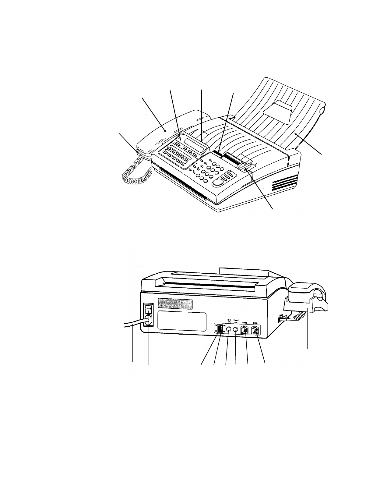
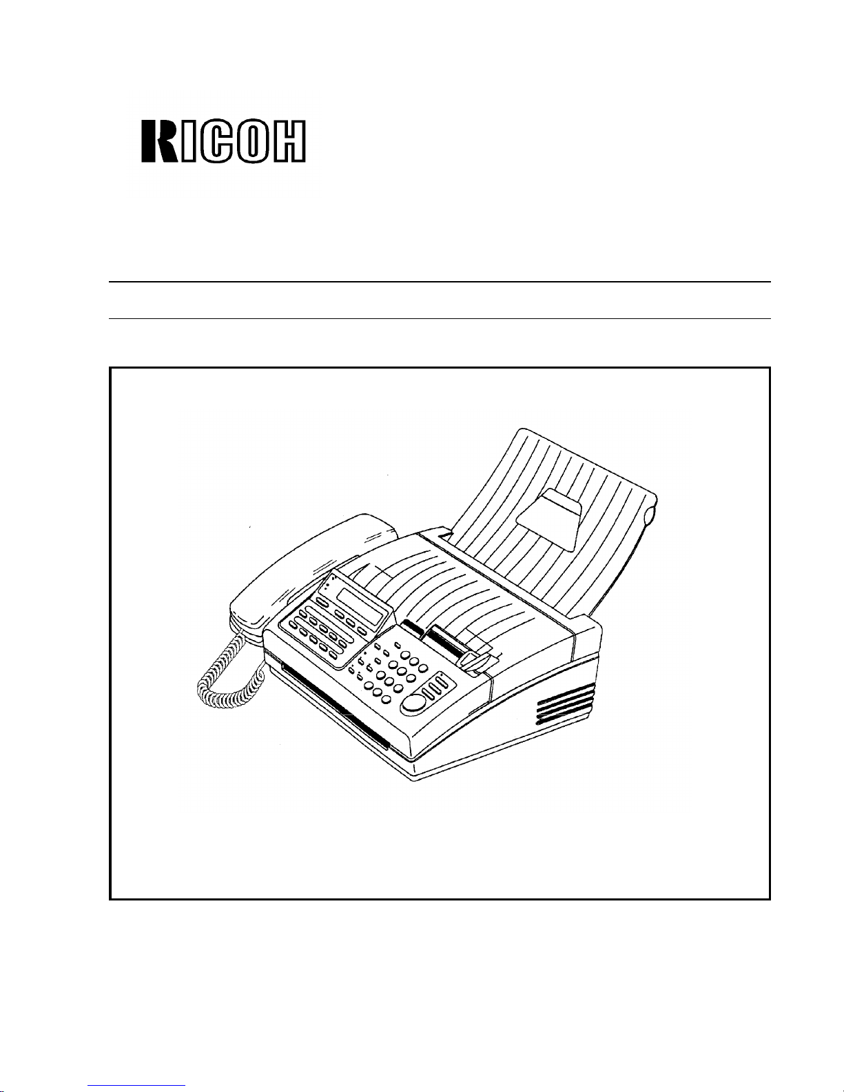
1-4. Exterior
1-4-1. Component Layout
1. Handset Cradle
This contains a
hook switch and a
ringer.
2. Telephone Handset
This contains a microphone and an
earphone.
3. ADF
Up to 5 pages can
be fed automatically.
4. Operation Panel
Refer to section 1-4-
2.
5. Printer Cover/Cover
Release Lever
To open the cover,
push the release
lever forward and
pull up the cover.
6. Copy Tray
7. Document Guide
8. Power Switch
9. Power Cord
10. Speaker Volume Control
11. Ringer Volume Control
12. Pulse/Tone Switch
13. GS/FS Switch
… Not used
14. Telephone Jack
15. Line Jack
6
7
5
34
2
1
9
8
12
13
10
11 15 14
1
1-5
Page 7
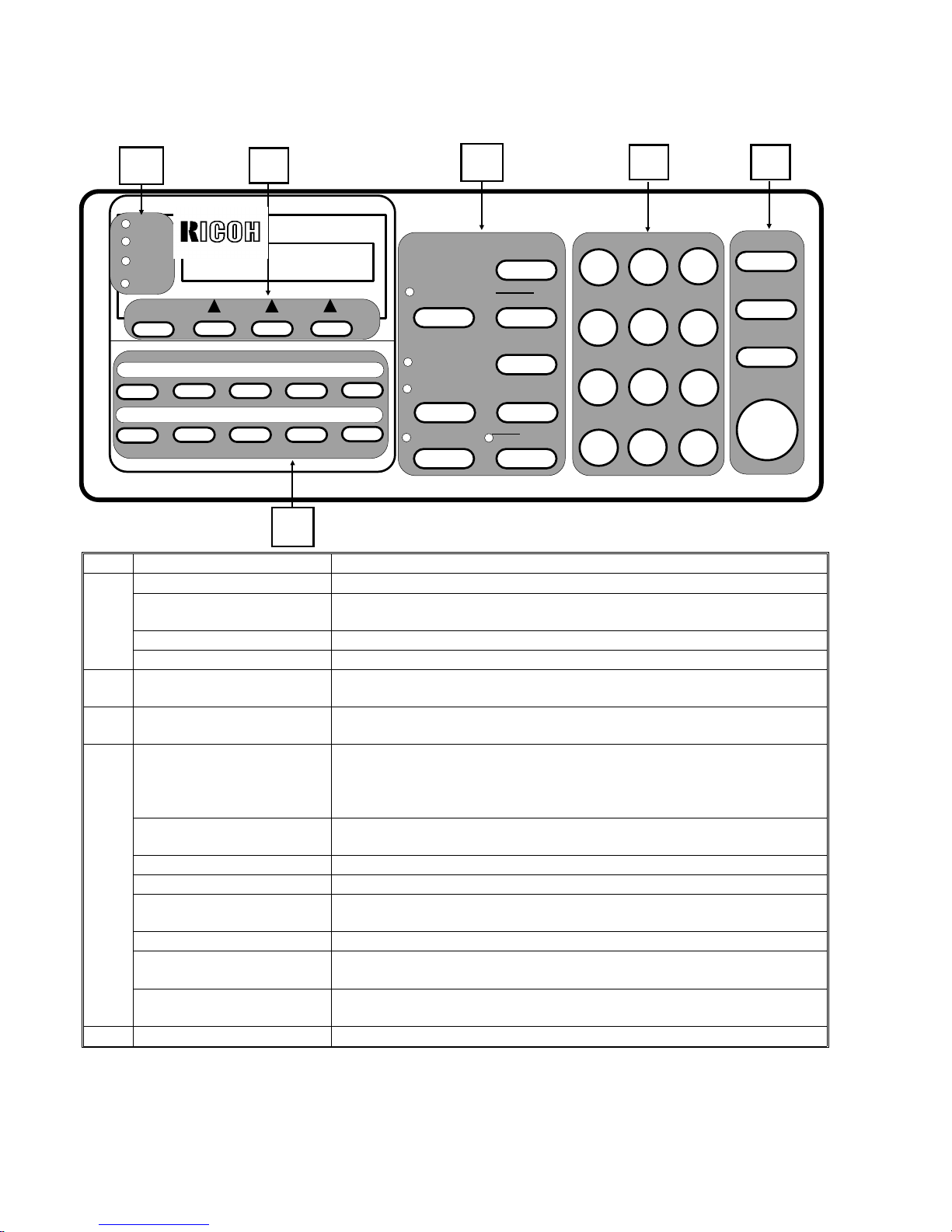
1-4-2. Operation Panel
No. Name Function
1
Power indicator Lights when the power is switched on.
Receive File indicator Lights when received messages are stored into memory because of a
printer problem. Up to 10 messages can be stored.
Check Display indicator Lights when the machine has a problem.
Replace Paper indicator Lights when the paper has been used up.
2
Function key and three
softkeys
Press to access a function in the function list, and choose one of the soft
keys below the required instruction indicated on the LCD.
3
Quick Dial keys Each of these keys can be programmed with a telephone number and a
label.
4
Auto Select key and indicator If it is not lit, Tel (manual receive) mode is selected.
If it is lit, either FAX (automatic receive) mode, AUTO (automatic Tel/Fax
switch) mode, or TAM (Telephone Answering Machine) mode is selected,
depending on the mode selected with function 04.
Resolution key and indicators Press this key to change the resolution. If neither of the Detail or Fine
indicators are lit, Standard resolution is selected.
Halftone key and indicator Press this key when you wish to send a photograph.
Speed Dial key Press this key to use a Speed Dial code.
Pause/Redial key Press this key when you want to enter a pause in a telephone number, or
when you want to redial one of the last five numbers dialed.
Clear key Press this during programming to erase the last character.
‘‘R’’(Recall) key* Press this key when you want to access the PSTN from behind a PBX
which requires the Flash Start method.
Hold/On Hook Dial key and
indicator*
Press this key to dial without picking up the handset. Also, press this key to
place the other party on hold during a telephone conversation.
5 Dialpad* Dial using these keys and use to input characters during programming.
>
>
>
RICOH FAX 240
Receive
File
Power
Check
Display
Replace
Paper
Function
A B
C D E
F
G H I J
Auto Select
Fine
Detail
Halftone
1
4
GHI
7
PRS
*
<
0
2
ABC
5
JKL
8
TUV
3
DEF
6
MNO
9
WXY
#
>
Memory
Stop
Copy
Start
Speed Dial
Pause
Redial
Clear
R
DIAL NUMBER
THEN INSERT DOCUMENT
11:22AM
Hold
On Hook Dial
OPER
1 2
3
4 5 6
1-6
Page 8

No. Name Function
6
Memory key (FAX240 only) Press to use memory transmission.
Stop key Press to stop the machine and return it to standby mode.
Copy key Press to copy the document now in the feeder.
Start key Press to start sending or receiving a fax message.
The keys with an asterisk (*) can be used for making a telephone call if the main power is switched off.
1-7
Page 9

2. PROGRAMMING, TESTING, AND PRINTING REPORTS
2-1. USER LEVEL PROGRAMMING
Function List
No. Function Brief Explanation
01
Quick Dial Programming Use to program a telephone number and a label in each Quick Dial
key.
02
Speed Dial Programming Use to program a telephone number and a label in each Speed Dial
code.
03
Telephone List Printing Use to print the telephone list, which contains Quick Dials, Speed
Dials, and Groups.
04
Set Fax Switch Use to select the function of Auto Select mode from among AUTO
mode (Auto Tel/Fax switch), TAM mode, and FAX mode (Automatic
Receive).
05 Send Later Use to program the machine to send a document at a later time.
06 Polling Transmission Use to set up a document to be polled from a remote terminal.
07 Polling Reception Use to program the machine to poll documents from remote terminals.
08
TCR Printing and On/Off Use to print a TCR or to set the machine up to print reception only on
the TCR.
09 Transmission Report On/Off Use to switch automatic Transmission Report output on or off.
10 Page Header (TTI) On/Off Use to switch the TTI printout on each transmitted page on or off.
11 Enter Page Header (TTI) Use to program the TTI.
12 Enter Your Name (RTI) Use to program the RTI.
13 Enter Your Fax Number (CSI) Use to program the CSI.
14 Clock Adjustment Use to adjust the date and time.
15 Set PBX Use to program the machine for the actual PBX type.
16
ID Code Programming Use to program the ID code, which is used for secured polling and the
closed network feature (closed network can only be switched on in
service mode).
17 Key Touch Tone On/Off Use to switch the key touch tone off or on.
18
RDS On/Off Use to switch RDS on or off.
This function cannot be accessed by the users, unless bit 6 of bit
switch 1 is set to 1 by RDS installation operation or by service later.
19 Set Language Use to change the LCD and report language.
20
Authorized Reception On/Off Use to prevent reception from terminals other than those programmed
in the Quick/Speed Dials.
21 Reviewing Stored Documents Use to review the documents stored in the memory.
22
Forwarding Use to program the machine to forward received messages to a
programmed terminal.
23 Group Dial Programming Use to make dialing groups (up to 5 groups can be made).
24 ECM On/Off Use this to switch ECM on or off.
2-1
Page 10

2-2. SERVICE LEVEL OPERATION
2-2-1. Entering and Exiting Service Mode
ENTERING SERVICE MODE
Press Start → Stop → Start → Stop → Start sequentially within 5 seconds.
After entering service mode, the following service functions are available.
No. Function Brief Explanation
Functions 30 to 38 are mainly prepared for factory use.
30 RAM Test Use to test the SRAM and DRAMs on the FCE.
31 Key Test Use to test all keys on the operation panel.
32 LED Test Use to test all LEDs on the operation panel.
33 LCD Test Use to test the LCD on the operation panel.
34 Speaker Test Use to test the monitor speaker.
35 Printer Test Use to print a test pattern.
36 PTT Test Use to test the modem signals, DTMF tones, and transmission level.
37 Frequency Test Use to generate signals of the desired frequency and level.
38
Burn-in Test Do not use this function. If this function is used, the RAM will all be
cleared.
The following functions are prepared for service use.
40
Factory Adjustment Use to check the ROM version, to adjust the tx level and to clear the
RAM.
41 Not used
42 Not used
43 Bit Switch Programming Use to change the bit switch settings.
44 Scanner Adjustment Mode Use to switch on the LED array for scanner adjustment.
91 Display ROM/RAM Data Use to display and change the ROM/RAM data.
92 Print System Report Use to print the system report.
93 Print ROM/RAM Data Use to print ROM/RAM data.
94 Not used
95 Print Service Report Use to print the service report.
96 Not used
97 Not used
98 NCU Parameter Programming Use to adjust the NCU parameters.
EXITING SERVICE LEVEL
Press Stop, Function, or EXIT at any time.
The machine will automatically exit service mode 40s after you enter it.
Note: In the functions, the new settings will not be saved by pressing the Function key. To save the new set-
tings, you have to press ‘‘SET’’ or ‘‘OK’’, then exit the service mode.
2-2
Page 11

2-2-2. RAM Test (Function 30)
1. Enter the service mode (see section 2-2-1).
2. Press Function, enter 30, then press SET.
3. The machine starts to check the SRAM and the two DRAMs without clearing any RAM data stored.
If the RAM test succeeded, the machine prints ‘‘RAM TEST OK’’, and goes to the Key Test.
If the RAM test failed, the machine displays ‘‘RAM ERROR AT ##AAAA’’ (## = type of RAM; AAAA = address)
for 3 s, then ‘‘RAM TEST FAILED’’ is printed
(Type of RAM: 09 = SRAM, 00 - DRAM0, 10 - DRAM1)
After this test, the machine automatically goes into function 31.
2-2-3. Key Test (Function 31)
1. Enter the service mode (see section 2-2-1).
2. Press Function, enter 31, then press SET.
3. The display shows the name of a key. If the key is pressed the display shows the next one until the last key ‘‘J’’
is pressed.
If the key test was successful, the machine prints ‘‘KEY TEST OK’’.
If the key test was failed or aborted, the machine prints ‘‘KEY TEST FAILED.
After this test, the machine automatically goes to the LED test.
Display Key Display Key Display Key
1 through # Keys in the
dialpad
ONL On Hook Dial CLR Clear
SPE Speed Dial FUN Function FIN Detail/Fine
MLT Memory LEF Softkey (Left) STO Stop
AUT Auto Select MID Softkey (Middle) CPY Copy
RED Redial RIG Softkey (Right) STA Start
HOL R PHO Halftone A through J Quick Dial keys
2-2-4. LED Test (Function 32)
1. Enter the service mode (see section 2-2-1).
2. Press Function, enter 32, then press SET.
3. All the LEDs on the operation panel blink sequentially until OK or ERROR is pressed.
If OK is pressed, the machine prints ‘‘LED TEST OK’’ and goes to the LCD test.
If ERROR is pressed, the machine prints ‘‘LED TEST FAILED’’, and goes to the LCD test.
2-2-5. LCD Test (Function 33)
1. Enter the service mode (see section 2-2-1).
2. Press Function, enter 33, then press SET.
3. The two lines on the LCD alternately show a line of solid black characters until OK or ERROR is pressed.
If OK is pressed, the machine prints ‘‘LCD TEST OK’’ and goes to the Speaker Test.
If ERROR is pressed, the machine prints ‘‘LCD TEST FAILED’’, and goes to the Speaker Test.
2-3
Page 12

2-2-6. Speaker Test (Function 34)
1. Enter the service mode (see section 2-2-1).
2. Press Function, enter 34, then press SET.
3. The machine emits a tone from the speaker until OK or ERROR is pressed.
If OK is pressed, the machine prints ‘‘VOL TEST OK’’ and goes to the Printer Test.
If ERROR is pressed, the machine prints ‘‘VOL TEST FAILED’’ and goes to the Printer Test.
2-2-7. Printer Test (Function 35)
1. Enter the service mode (see section 2-2-1).
2. Press Function, enter 35, then press PRINT.
3. A test pattern with diagonal lines is printed. After printing, the machine goes to standby mode.
2-2-8. PTT Test (Function 36)
1. Enter the service mode (see section 2-2-1).
2. Press Function, enter 36, then press SET.
3. Press ‘‘MDM’’ for modem test, ‘‘DTMF’’ for DTMF test, or ‘‘LEV.’’ for tx level adjustment.
4.1 Modem Test
The test starts from silence (the machine only goes off-hook), then by pressing the # key consecutively, the signal changes to 9,600bps - 7,200bps - 4,800bps - 2,400bps - 300bps - 600Hz - 1100Hz - 2100Hz. (Press the *
key to go backwards through the sequence.)
After you have finished the test, press Stop to go back to step 3.
4.2 DTMF Test
Press a key on the dialpad (0 - 9, * and #) to test the DTMF signal.
After you have finished the test, press Stop to go back to step 3.
Note that the machine will emit a DTMF signal of the correct length for the country code, even if the slide
switch on the rear of the machine is not set at ‘‘Tone’’.
If you wish to get a continuous DTMF tone, set the slide switch at ‘‘Tone’’, switch off the power, then press the
required key on the dialpad.
4.3 Tx Level Adjustment
The current tx level setting is displayed in the upper right corner of the LCD. To change the setting, press # to
increment or press * to decrement. After adjustment, press Stop to save the setting.
2-2-9. Frequency Test (Function 37)
1. Enter the service mode (see section 2-2-1).
2. Press Function, enter 37, then press SET.
3. The machine emits a sine wave of the displayed frequency. The frequency can be changed in units of 100Hz
by pressing # (increment) or * (decrement). Also, the output level can be changed by pressing LEV.
2-2-10. Burn-in Test (Function 38)
Do not use this function.
2-4
Page 13

2-2-11. Factory Adjustment (Function 40)
1. Enter the service mode (see section 2-2-1).
2. Press Function, enter 40, then press SET.
The upper line on the LCD shows the ROM version ‘‘VER x.xx dd.mm.yy c’’ (x.xx = version, dd.mm.yy = date, c
= country setting). The lower line on the LCD shows ‘‘CLK 0.LEV RAMC’’.
3. Press RAMC for RAM clear.
4.1 Clock Oscillator Adjustment
This function is not for service.
WARNING: Do not use this function.
4.2 Tx Level Fine Adjustment
This function is not for service.
WARNING: Do not use this function.
4.3 RAM Clear
RAM is all reset to the initial settings and the CPU is restarted.
WARNING: With this function, all the previous settings will be reset to the initial settings for Hong Kong.
Program the correct country code after clearing the RAM (bit switch 2; see section 3-1).
2-2-12. Bit Switch Programming (Function 43)
1. Enter the service mode (see section 2-2-1).
2. Press Function, enter 43, then press SET.
3. The setting of bit switch 0 is displayed.
To change the setting of a bit, press the bit number on the dialpad (0 - 7). Press < or > to display other bit
switches.
4. To store the new setting, press OK.
Important Notice for Back-to-Back Mode (Bit Switch 0, Bit 7)
When in back-to-back mode, you cannot enter service mode unless you exit back-to-back mode first. This is because the machine starts communication if you press Start - Stop - and so on while you are in back-to-back mode.
To exit back-to-back mode, do the following:
1. Make sure that the machine is not communicating.
2. Press Halftone to light the Halftone LED, then press Stop.
3. Enter the service mode.
4. After finishing with service mode, re-enter back-to-back mode if required.
2-2-13. Scanner Adjustment (Function 44)
1. Enter the service mode (see section 2-2-1).
2. Press Function, enter 44, then press SET.
3. The LED array is switched on until ‘‘OK’’ is pressed. Refer to section 4-5 for more details on scanner adjustment.
2-5
Page 14

2-2-14. Display and Rewrite ROM/RAM Data (Function 91)
1. Enter the service mode (see section 2-2-1).
2. Press Function, enter 91, then press SET.
3. The upper line on the LCD shows ‘‘ADD: aaaa VAL: ddd/hh’’ (aaaa = address, ddd = decimal value of the data,
and hh = hexadecimal value of the data).
4. Select the address where the data you want to display or change is stored, using keys 0 through 9 and Quick
Dial keys A through F, or using the * key to decrement the address and the # key to increment the address.
5. Press EDIT if you want to rewrite the data.
6. Rewrite the data in the hexadecimal data field. (The ‘‘<’’ and ‘‘>’’ keys are used to move the cursor in the data
field.)
7. Press OK to save the new data.
8. Press Stop to exit this function or go back to step 3 to change another address.
2-2-15. System Report (Function 92)
1. Enter the service mode (see section 2-2-1).
2. Press Function, enter 92, then press PRINT. The system report will be printed.
2-2-16. Print ROM/RAM Data (Function 93)
1. Enter the service mode (see section 2-2-1).
2. Press Function, enter 93, then press SET.
3. Enter the start address then press OK.
The address field has 5 digits, as the first digit is used for bank identification and the following 4 digits are for
the actual address. Use the bank identification number ‘‘0’’ for addresses 0000 - 3FFF(H) and C000 - FFFF(H),
and ‘‘9’’ for addresses 4000 - 7FFF(H).
4. Enter the end address then press OK. The machine prints a list of ROM/RAM data in the selected address
range.
2-2-17. Service Report (Function 95)
1. Enter the service mode (see section 2-2-1).
2. Press Function, enter 95, then press PRINT. The service report will be printed.
2-2-18. NCU Parameter Programming (Function 98)
1. Enter the service mode (see section 2-2-1).
2. Press Function, enter 98, then press SET.
3. The upper line on the LCD shows ‘‘ADD: aa VAL: ddd/hh’’ (aa = parameter number, ddd = decimal value of the
data, and hh = hexadecimal value of the data).
4. Select the required parameter number with keys 0 through 9, or press # or * to scroll through the parameters.
5. Press EDIT if you want to change the data.
6. Rewrite the data in the decimal data field. (The ‘‘<’’ and ‘‘>’’ keys are used to switch the cursor between the address and data fields, and the * and # keys are used to decrement/increment the data value.)
Refer to section 3-2-1 (address 0377 - 0381 (H)) for the definition of NCU parameters.
2-6
Page 15

3. SERVICE TABLES
3-1. BIT SWITCHES
WARNING
Do not adjust a bit switch that is described as "Not used", as this may cause the machine to
malfunction or to operate in a manner that is not accepted by local regulations.
Bit Switch 0
FUNCTION SETTINGS COMMENTS
0 Not used
1 Rx cable equalizer 0: Disabled
1: Enabled
Set this bit to 1 when there is a serious signal loss at
higher frequencies during reception. The cable
equalizer will amplify the signal in this range by +3
dBm.
2 DIS detections 0: Once
1: Twice
The machine will send DCS (G3 set-up signal) if it
receives DIS. If echoes are frequent, setting this bit
to 1 will allow the machine to wait for the second DIS
before sending DCS.
3 TSI (RTI) printout on
received copies
0: Disabled
1: Enabled
If this bit is 1, the TSI or RTI received from the
sender will be printed on the top of each page.
4 Burst error threshold/
error line ratio
0: 6 (12) [24] lines/10%
1: 3 (6) [12] lines/5%
If there are more consecutive error lines in the
received page than the threshold specified by this bit,
the page is rejected. Values in parenthesis ( ) are for
Detail resolution, and those in square brackets [ ] are
for Fine resolution.
Also, if the number of error lines divided by the total
number of lines reaches the ratio determined by this
bit, the machine will send RTN to the other end.
If you want to receive messages with fewer error
lines, set this bit to 1.
5 Training error threshold 0: 4 bits
1: 1 bit
If the machine detects more errors during training
than the number set by this bit, training fails and the
machine will send FTT to ask the other terminal for
modem rate shift-down.
Set this bit to 1 if you want to receive messages at a
more reliable modem speed.
6 Initial Rx modem rate 0: 9,600 bps
1: 4,800 bps
The setting of this bit is used to inform the sending
machine of the initial starting modem rate for the
machine in receive mode. If 9,600 bps presents a
problem during reception, use 4,800 bps.
7 Back to back test 0: Disabled
1: Enabled
Set this bit to 1, when you want to test a back-toback communication.
Important Notice for Back-to-Back Mode
When in back-to-back mode, you cannot enter service mode unless you exit back-to-back mode first. This is because the machine starts communication if you press Start - Stop - and so on to enter service mode while you are
still in back-to-back mode.
Refer to the notice in section 2-2-12 for how to exit back-to-back mode.
3-1
Page 16

Bit Switch 1
FUNCTION SETTINGS COMMENTS
0 Reconstruction time for
the first line
0: 6 seconds
1: 10 seconds
When the sending terminal is controlled by a
computer, there may be a delay in receiving page
data after the local machine accepts set-up data and
sends CFR. If this occurs, set this bit to 1 to give the
sending machine more time to send data.
1 Substitute reception file
forwarding (FAX240 only)
0: Normal operation
1: Forward all files
Set this bit to 1 if the printer is out of order.
The machine will forward all files to the Forwarding
terminal.
2 ECM
transmission/reception
(FAX240 only)
0: Enabled
1: Disabled
Set this bit to 1 when you want to switch off ECM.
3 PSTN/PBX dial tone and
busy tone detection
0: Enabled
1: Disabled
Set this bit to 1 when you wish to disable tone
detection.
4 Closed network in
reception
0: Disabled
1: Enabled
Set these bits to 1 to switch on Closed Network.
With Closed Network, communication will not go
ahead if the ID code of the other terminal does not
match the ID code of this terminal.
The ID code has to be programmed with function 16
before switching on these bits.
This feature may not be reliable when
communicating with another maker’s machine.
5 Closed network in
transmission
0: Disabled
1: Enabled
6 Remote read/write request 0: Always enabled
1: User selectable
0: RDS is always enabled. The user cannot switch it
off.
1: If a technician or RDS operator sets this to 1 after
installation, the user can select either ‘‘ON for 24
hours’’ or ‘‘OFF’’.
7 Communication
parameter display and
line monitoring after
handshaking
0: Disabled
1: Enabled
This is a fault-finding aid. If this bit is set to 1, the
LCD shows the key parameters (see below) and the
speaker is enabled during message transmission and
reception.
This should be normally disabled because it cancels
the CSI/TSI (RTI) display for the user.
Modem rate
(bps)
Sub-scan
resolution
(lines/mm)
Coding Width and
reduction
Mode I/O rate
(ms/line)
96: 9,600
72: 7,200
48: 4,800
24: 2,400
S: 3.85
D: 7.7
F: 15.4
1D: MH
2D: MR
1E: MH + EFC
2E: MR + EFC
1S: MH + SSC
2S: MR + SSC
1C: MH + ECM
2C: MR + ECM
MC: MMR + ECM
A: A4
N: No reduction
DCS: CCITT G3
NSS:
Non-standard G3
0M: 0
5M: 5
10M: 10
20M: 20
40M: 40
3-2
Page 17

Bit Switch 2
FUNCTION SETTINGS COMMENTS
0 Country code
Bit 4 3 2 1 0 Country
1 0 0 0 1 USA
1 0 1 0 0 Hong Kong
1 0 1 0 1 Australia
1 0 1 1 0 New Zealand
1 0 1 1 1 Israel
1 1 0 0 0 Thailand
1 1 0 0 1 Singapore
1 1 0 1 0 Indonesia
Set the country code after clearing the RAM.
1
2
3
4
5 TAM interface type 0: Normal
1: German type
0: The normal type of TAM interface monitors the line
current on the LIU, to detect whether the external
TAM goes off-hook or on-hook.
1: The German type of TAM interface does not
monitor the line current on the LIU, because the TAM
and the fax are connected in parallel to the line.
Refer to section 1-3-1 for more details.
6 TAM (Telephone
Answering Machine)
interface
0: Enabled
1: Disabled
If this bit is 1, TAM mode cannot be selected with
function 04 by the user.
7 Not used
Default Settings
Bit Switch H501/502-50 H501/502-51 H501/502-52 H501/502-53 H501/502-54 H501/502-55
0 00 00 00 00 00 00
1 00 00 00 00 00 00
2 14 15 16 1A 17 11
3-3
Page 18

3-2. USEFUL RAM ADDRESSES
In the equations that occur in the following tables, N represents the decimal value stored in the RAM address.
WARNING
Changing any RAM data that are not listed in this table may cause the machine to malfunction.
3-2-1. Address Table
Use service function 91 to view or adjust the contents of a RAM address. See section 2-2-14 for details.
Address (Hex) Function
0000 - 0002
Bit switches 00 to 02 (0000 = Bit switch 00, 0001 = Bit switch 01, and so on); refer to section 3-1
for details.
0009
User function parameters
Bit 7: Transmission Report On/Off [Function 09] (1: On)
Bit 6: TTI (Page Header) On/Off [Function 10] (1: On)
Bit 5: Key Touch Tone On/Off [Function 17] (1: On)
Bit 4: RDS On/Off [Function 18] (1: On for 24 hours)
Bit 3: AM/PM Indication on LCD clock Note 1 (1: On)
Bit 2: Forwarding On/Off [Function 22] Note 2 (1: On)
Bit 1: Forwarding Mode [Function 22] Note 2 (0: Now or Later mode, 1: Daily mode)
Bit 0: Forwarding File Local Printing On/Off [Function 22] (1: On)
000A
User function parameters
Bit 7: Communication record listing on TCR [Function 08] (1: On)
Bit 6: Authorized Reception On/Off [Function 20] (1: On)
Bits 5 through 0: Not used
0039
Exchanger type connected to the machine Bit 2 = 0: PSTN
Bit 2 = 1: PBX
0300 - 0302: Line current detection parameters
0300 Line current detection time [Time = N x 10 (ms), detection disabled if N = FF]
0301 Line current reset time [Time = N x 20 (ms)]
0302 Line current dropout detection time [Time = N x 10 (ms)]
0303 - 0320: PSTN tone detection parameters
0303 - 030E
Modem data for PSTN dial tone frequency range
Caution: Do not adjust.
030F PSTN dial tone detection time [Time = N x 20 (ms), detection disabled if N = FF]
0310 PSTN dial tone reset time [Time = N x 0.16 (s)]
0311 PSTN dial tone continuous tone time [Time = N x 20 (ms)]
0312 PSTN dial tone permissible dropout time [Time = N x 20 (ms)]
0313 PSTN pause time [Time = N x 0.16 (s)]
0314 PSTN ringback tone detection time [Time = N x 20 (ms), detection disabled if N = FF]
0315 - 0320
Modem data for PSTN busy tone frequency range
Caution: Do not adjust.
0321 - 033E: PBX tone detection parameters
0321 - 032C
Modem data for PBX dial tone frequency range
Caution: Do not adjust.
032D PBX dial tone detection time [Time = N x 20 (ms), detection disabled if N = FF]
032E PBX dial tone reset time [Time = N x 0.16 (s)]
032F PBX dial tone continuous tone time [Time = N x 20 (ms)]
3-4
Page 19

Address (Hex) Function
0330 PBX dial tone permissible dropout time [Time = N x 20 (ms)]
0331 PBX pause time [Time = N x 0.16 (s)]
0332 PBX ringback tone detection time [Time = N x 20 (ms), detection disabled if N = FF]
0333 - 033E
Modem data for PBX busy tone frequency range
Caution: Do not adjust.
033F - 0348: Busy tone detection parameters
033F Busy tone ON time (range 1) [Time = N x 10 (ms)]
0340 Busy tone OFF time (range 1) [Time = N x 10 (ms)]
0341 Busy tone ON time (range 2) [Time = N x 10 (ms)]
0342 Busy tone OFF time (range 2) [Time = N x 10 (ms)]
0343 Busy tone ON time (range 3) [Time = N x 10 (ms)]
0344 Busy tone OFF time (range 3) [Time = N x 10 (ms)]
0345 Busy tone ON time (range 4) [Time = N x 10 (ms)]
0346 Busy tone OFF time (range 4) [Time = N x 10 (ms)]
0347 Continuous busy tone detection time [Time = N x 10 (ms)]
0348
Bits 0 to 3: Busy tone signal state time tolerance (for all ranges)
Bit 3 2 1 0 Tolerance
0 0 0 1 ± 50%
0 0 1 0 ± 25%
0 0 1 1 ± 12.5%
Bits 4 to 7: Number of cycles required for detection
0349 - 0359: International dial tone detection parameters
0349 - 0354
Modem data for international dial tone frequency range
Caution: Do not adjust.
0355 International dial tone detection time [Time = N x 20 (ms), detection disabled if N = FF]
0356 International dial tone reset time [Time = N x 0.16 (s)]
0357 International dial tone continuous tone time [Time = N x 20 (ms)]
0358 International dial tone permissible dropout time [Time = N x 20 (ms)]
0359 International dial pause time [Time = N x 0.16 (s)]
035A - 036A: National dial tone detection parameters
035A - 0365
Modem data for domestic dial tone frequency range
Caution: Do not adjust.
0366 National dial tone detection time [Time = N x 20 (ms), detection disabled if N = FF]
0367 National dial tone reset time [Time = N x 0.16 (s)]
0368 National dial tone continuous tone time [Time = N x 20 (ms)]
0369 National dial tone permissible dropout time [Time = N x 20 (ms)]
036A National dial pause time [Time = N x 0.16 (s)]
036B - 036C
International dial access number
Example: If the number is 100, store F1 in address 036B, and 00 in address 036C.
036D PBX operator pause [Time = N x 20 (ms)]
036F CCITT T1 time [Time = N x 2.56 (s)]
0370 Maximum number of dialing attempts to the same station in normal tx mode
0371 Redial interval in normal tx [Time = N (minutes)]
0372 Maximum number of dialing attempts to the same station in memory tx mode
0373 Interval between dialing to different stations [Time = N x 2.56 (s)]
0374 Dial tone detection level [Level = 0 - N x 0.375 (dBm)]
0375 Busy tone detection level [Level = 0 - N x 0.375 (dBm)]
0376
Minimum signal detection level [Level = 0 - N x 0.375 (dBm)]
3-5
Page 20

Address (Hex) Function
0377 - 037B: Ringing signal detection parameters (Use function 98 to change)
0377
NCU Parameter 00: Acceptable ringing signal frequency, upper limit
[Frequency = 1/(N x 10-3) (Hz)]
0378
NCU parameter 01: Acceptable ringing signal frequency, lower limit
[Frequency = 1/(N x 10-3) (Hz)]
0379 NCU parameter 02: Number of rings until a call is detected [Number = N x 1]
037A NCU parameter 03: Minimum required length of a ring [Length = 20 x N (ms)]
037B NCU parameter 04: Minimum required length of an interval between rings [Length = 40 x N (ms)]
037C - 037D: Pulse dial parameters (Use function 98 to change)
037C NCU parameter 05: Time between closing the dc loop and the first dialed digit [Time = N (ms)]
037D NCU parameter 06: Pause between dialed digits (pulse dial mode) [Time = N x 20 (ms)]
037E
NCU parameter 07: Time waited when a pause is entered at the operation panel [Time = N x 20
(ms)]
037F - 0380: Tone dial parameters (Use function 98 to change)
037F NCU parameter 08: DTMF tone length [Time = N x 5 + 60 (ms)]
0380 NCU parameter 09: Time between dialed digits (DTMF dial mode) [Time = N x 5 + 60 (ms)]
0381 NCU parameter 10: Modem transmission level [Level = - N (dBm)]
0382
Language selected for LCDs and reports
0(D): English 1(D): Spanish 3(D): French
0386 Redial interval for memory transmission [ N x 1 (min.)] (Default: 5 minutes)
0387 - 0388 Intercity access code for France: 16(D) [0386 = FF(H), 0387 = 16(BCD)]
039A
Ringing time in Auto mode [Time = N (s)]
The value of N should be a multiple of 5 between 5 and 25.
039E - 03A1: CNG detection parameters
039E Maximum acceptable CNG OFF-time [Time = N x 20 (ms)] Note 3
039F Minimum acceptable CNG OFF-time [Time = N x 20 (ms)] Note 3
03A0 Maximum acceptable CNG ON-time [Time = N x 20 (ms)] Note 3
03A1 Minimum acceptable CNG ON-time [Time = N x 20 (ms)] Note 3
03A2
Country code
11: USA 14: Hong Kong 15: Australia 16: New Zealand 17: Israel 18: Thailand
19: Singapore 1A: Indonesia
03C5
Mode selection in Auto Select mode
Bit 3 2 1 0 Mode
0 0 0 1 Auto Tel/Fax switch with AVM
0 0 1 0 Auto Tel/Fax switch with ringback tone
0 0 1 1 Semi-Auto (TAM) mode
0 1 0 0 Fax mode
03C9 Continuous silent period detection time in TAM mode [Time = N x 65 (ms)]. See Note 4.
03CA PSTN access code from behind Loop Start PBX (BCD)
03CF Number of rings until a call is detected in TAM mode [N (times)]
20A1 Forwarding start date and time Minute (BCD)
20A2 Forwarding start date and time Hour (BCD)
20A3 Not used
20A4 Forwarding start date and time Day (BCD)
20A5 Forwarding start date and time Month (BCD)
20A6 Forwarding start date and time Year (BCD)
20A7 Forwarding end date and time Minute (BCD)
20A8 Forwarding end date and time Hour (BCD)
20A9 Not used
3-6
Page 21

Address (Hex) Function
20AA Forwarding end date and time Day (BCD)
20AB Forwarding end date and time Month (BCD)
20AC Forwarding end date and time Year (BCD)
20AD - 226E TCR generation area (30 bytes x 15 communications)
2272 - 2433 Service report and error report generation area (45 bytes x 10 communications)
2438 - 24F7 Error code memory (up to 32 codes x 6 bytes)
2736 - 2737
Polling ID code Example: ABCD 2736 (High) = A, (Low) = B
2737 (High) = C, (Low) = D
2A7B Received page counter High: Tens digit Low: Units digit
(BCD) High: Thousands digit Low: Hundreds digit
High: Hundred thousands digit Low: Ten thousands digit
2A7C
2A7D
2A7E - 2A80 Transmitted page counter (Refer to the received page counter)
2A81 Printed page counter High: Tens digit Low: Units digit
(BCD) High: Thousands digit Low: Hundreds digit
High: Hundred thousands digit Low: Ten thousands digit
2A82
2A83
2A84 - 2A86 Scanned page counter (Refer to the printed page counter)
5002 - 5100
Modem rates used in the last five communications to the terminals programmed in the
Quick/Speed dials and to the forwarding terminal. (5 bytes x 51 destinations)
[0: No history, 1: 2400 bps, 2: 4800 bps, 3: 7200 bps, 4: 9600 bps]
5101 Number of characters in the RTI - 14 (H)
5102 - 5115 RTI (ASCII)
5116 Number of characters in the CSI - 14 (H)
5117 - 512A CSI (ASCII)
512B Number of characters in the TTI - 20(H)
512C - 514B TTI (ASCII)
514C Number of digits in the forwarding terminal’s telephone number
514D - 516C Forwarding terminal’s telephone number (ASCII)
63F6
Continuous silent period detection time in TAM mode indicated on the LCD [Time = N (s)].
See Note 4.
6408
AVM language in AUTO and TAM modes.
1(D): English 2(D): German 3(D): Dutch 4(D): French
6409 Second AVM language in AUTO and TAM modes. (Same as above)
ROM Version •
The following addresses are ROM addresses. The data in these addresses cannot be changed.
C00C Version (High) (ASCII)
C00D A period ‘‘ . ’’ (ASCII)
C00E Version (Low) (ASCII)
C00F Version (Low) (ASCII)
C010 A blank space ‘‘ ’’ (ASCII)
C011 Day (Tens digit) (ASCII)
C012 Day (Units digit) (ASCII)
C013 A period ‘‘ . ’’ (ASCII)
C014 Month (Tens digit) (ASCII)
C015 Month (Units digit) (ASCII)
C016 A period ‘‘ . ’’ (ASCII)
C017 Year (Tens digit) (ASCII)
C018 Year (Units digit) (ASCII)
C019 A blank space ‘‘ ’’ (ASCII)
3-7
Page 22

Address (Hex) Function
C01A Hour (Tens digit) (ASCII)
C01B Hour (Units digit) (ASCII)
C01C A colon ‘‘:’’ (ASCII)
C01D Minute (Tens digit) (ASCII)
C01E Minute (Units digit) (ASCII)
C01F A blank space ‘‘ ’’ (ASCII)
C020 Suffix (ASCII)
C021 Machine code 13 (H) - FAX 220/240
Notes:
1. This bit only changes the language displayed on the LCD. The report language cannot be changed.
2. Forwarding requires the following switches and data.
ON/OFF
Bit 2 of 0009 (H)
Mode
Bit 1 of 0009 (H)
Start Date and Time
20A1 - 20A6 (H)
End Date and Time
20A7 - 20AC (H)
OFF
(0)
ON
(1)
NOW (0) Current date and time is stored. End time and date is stored
here (user programmable).
If ‘‘UNDEFINED’’ is selected,
the start date and time is copied
here.
LATER (0)
Start date and time is stored
here (user programmable).
DAILY (1)
The daily start time is stored
here.
The daily end time is stored
here.
3. These addresses are cleared if the power is switched off.
4. If you change RAM address 63F6, you must also change RAM address 03C9, and vice versa.
3-8
Page 23

3-2-2. Format of the TCR and Transmission Report Generation Areas
The TCR and the Transmission Report are generated in addresses 20AD - 226E (H). The record of each communication is stored in blocks of 30 bytes as explained in the following table.
Byte No. Functions
0
Header Bit 7: Transmission Report (1: Enabled)
Bit 6: TCR (1: Enabled)
Bits 5 through 0: Not used
1 Communication start time Month (BCD)
2 Communication start time Day (BCD)
3 Communication start time Hour (BCD)
4 Communication start time Minute (BCD)
5 - 24 Remote terminal’s RTI, TSI or CSI (ASCII)
25
Communication mode
Bit 7: Resolution step down (1: Yes)
Bit 6: Reduction (1: Yes)
Bit 5: 0: Standard 0: Fine 1: Detail 1: Not used
4 0 1 0 1
Bit 3: Forwarding (1: On)
Bit 2: Memory tx/rx (1: Yes)
Bit 1: ECM (0: Non-ECM, 1: ECM)
Bit 0: Tx or Rx (0: Rx, 1: Tx)
26 Communication time Minutes (BCD)
27 Communication time Seconds (BCD)
28
Communication result and causes of error
Bit 7: Result (0: OK, 1: Error)
Bit 6: Document jam (1: Yes)
Bit 5: Authorized reception (0: Not rejected, 1: Rejected)
Bit 4: Not used
Bit 3 - 0: Cause of error (BCD)
7 (BCD): Not used
6 (BCD):
5 (BCD): 8 minutes close
4 (BCD): Busy
3 (BCD): T1 time over during a telephone call
2 (BCD): T1 time over during a fax call
1 (BCD): Errors during fax communication
0 (BCD): No error
29 Total page(s) (BCD)
3-9
Page 24

3-2-3. Format of the Service Report and Error Report Generation Area
The Service Report and the Error Report are generated in addresses 2272 - 2433 (H). The record of each error
communication is stored in blocks of 45 bytes as explained in the following table. There can be up to 10 records.
Byte No. Functions
0
Header Bit 7: Service Report or Error Report (1: Enabled)
Bit 6 through 0: Not used
1 - 29 Same as the TCR memory
30 Error page #1 (BCD)
31 Error page #2 (BCD)
32 Error page #3 (BCD)
33 Error page #4 (BCD)
34 Error page #5 (BCD)
35 Error code #1 (High) (BCD)
36 Error code #1 (Low) (BCD)
37 Error code #2 (High) (BCD)
38 Error code #2 (Low) (BCD)
39 Error code #3 (High) (BCD)
40 Error code #3 (Low) (BCD)
41 Error code #4 (High) (BCD)
42 Error code #4 (Low) (BCD)
43 Error code #5 (High) (BCD)
44 Error code #5 (Low) (BCD)
3-2-4. Format of the Error Code Memory
The error codes are stored in 2438 - 24F7 (H). Each error code is stored in blocks of 6 bytes as explained in the following table. The machine can store up to 32 error codes.
Byte No. Functions
0 Error code (High) (BCD)
1 Error code (Low) (BCD)
2 Month (BCD)
3 Day (BCD)
4 Hour (BCD)
5 Minute (BCD)
3-10
Page 25

3-3. JUMPERS
LIU
1
TB1
1
TB2
1 TB3
1
TB4
The jumper wires are set as shown below in the factory for each version.
WARNING: Service parts for types 1, 4, and 6 are set to type 6, and service parts for types 2 and
3 are set to type 2. When installing a new LIU, make sure that it is at the correct setting for the machine. Also, note that the LIU for type 2 has a dummy jumper on pin 4 of TB3; this is a spare
jumper for use if you wish to install the LIU board in a type 3 machine.
1
TB1
1
TB2
1 TB3
1
TB4
1
TB1
1
TB2
1 TB3
1
TB4
1
TB1
1
TB2
1 TB3
1
TB4
1
TB1
1
TB2
1 TB3
1
TB4
1
TB1
1
TB2
1 TB3
1
TB4
H501/502-50
(Type 1)
H501/502-52
(Type 3)
H501/502-53
(Type 4)
H501/502-54
(Type 5)
H501/502-55
(Type 6)
1
TB1
1
TB2
1 TB3
1
TB4
H501/502-51
(Type 2)
Dummy Jumper
3-11
Page 26

3-4. VARIABLE RESISTORS AND SWITCHES
PCB Address Function
LIU
VR1 Ringer volume adjustment (user adjustable)
VR2 Speaker volume adjustment (user adjustable)
VR3 DTMF signal Tx level adjustment
SW1 GS/FS select switch (not used)
PSU S001
A thermostat; this switches the power off automatically when the temperature goes higher
than 95 ± 5 °C, and recovers after switching the power switch off and on
3-5. SENSORS
No. Name Function
SB-1
Document Sensor Detects whether a document is placed in the feeder or not. The 58th bit on
the SBU is used as this sensor.
SB-2
Scan Line Sensor Detects when the top of a page is at the scan line position. The 4th bit on
the SBU is used as this sensor.
SB-4 Paper End Sensor Detects whether paper is in the paper holder or not.
SB-5 Paper Jam Sensor Detects whether paper is jammed in the printer or not.
SB-7 Cutter Start Sensor Detects whether the cutter blade is at the home (start) position or not.
SB-8
Cutter End Sensor Detects whether the cutter blade is at the end position or not. If the cutter
blade is detected at the cutter end position, the cutter motor reverses to
move the blade to the cutter start position.
SB-10 Cover Sensor Detects whether the printer cover is closed or not.
3-12
Page 27

4. REMOVAL AND ADJUSTMENT
CAUTION
1.Unplug the machine from the power outlet before removing any of the covers.
2. The danger of explosion exists if the lithium battery on the FDU is incorrectly replaced. Replace
only with the same or an equivalent type recommended by the manufacturer. Discard used batteries
in accordance with the manufacturer’s instructions.
4-1. COVERS
4-1-1. Operation Panel Assembly
1. Open the ADF.
2. Remove the operation panel cover [A] as shown below.
3. Disconnect three connectors.
4. Remove the lower cover [B] (1 ground wire).
[A]
[B]
4-1
Page 28

4-1-2. Paper Holder and Scanner Cover
1. Open the printer cover.
2. Remove the paper holder [A] (4 screws, 1 connector).
3. Remove the operation panel assembly (see section 4-1-1).
4. Remove the scanner cover [B] with a screwdriver as shown below (2 screws).
[A]
[B]
4-2
Page 29

4-1-3. Thermal Head and Printer Cover
1. Open the printer cover.
2. Remove the thermal head cover [A] (4 screws).
3. Remove the thermal head [B] and the spring plate [C] (2 connectors, 2 springs, 2 screws).
Reassembly Note
• The dents on the thermal head bracket must fit into the slots on the thermal head.
4. Remove the printer cover [D] (2 screws).
[D]
[A]
[C]
[B]
4-3
Page 30

4-2. SCANNER
4-2-1. Separation Rubber Plate
1. Remove the operation panel assembly (see section 4-1-1).
2. Remove the rubber plate [A].
4-2-2. LED Array
1. Remove the operation panel assembly, the paper holder and the scanner cover (see section 4-1).
2. Remove the LED array [A] (2 screws, 1 connector).
[A]
[A]
4-4
Page 31

4-2-3. Feed Roller
1. Remove the operation panel assembly, the paper holder and the scanner cover (see section 4-1).
2. Remove the metal bracket [A] (1 screw).
3. Remove the feed roller [B].
Note for Reassembly
• Pin [C] on the document sensor actuator must be under the feed roller shaft.
[A]
[B]
[C]
4-5
Page 32

4-3. PRINTER
4-3-1. Rear Cover, Cutter Unit (FAX240 only), and Platen Roller
1. Remove the rear cover [A] (2 screws).
2. Remove the paper guide bracket [B] (FAX220), or the paper holder and the cutter unit [C] (FAX240) (4 screws,
2 connectors).
[C]
[A]
FAX240
[B]
FAX220
[A]
4-6
Page 33

3. Remove the FCE, FDU, PSU and LIU (see section 4-4).
4. Remove the mono-chassis [D] (2 screws, 1 ground wire).
5. Remove two gears [E] (1 E-ring).
6. FAX220: Remove the platen roller [F] (2 E-rings, 2 bushings).
FAX240: Remove the decurler bracket [G] and platen roller [F] (2 E-rings, 2 bushings, 1 spring).
Reassembly Note
• Be careful not to assemble the gears the wrong way round.
• The left platen roller bushing is smaller than right bushing.
• FAX240: Lubricate the left shaft of the platen roller all the way round after changing the platen roller or the
spring clutch for the decurler (Use Mobil Temp 78, part no. 54479078).
[D]
[E]
[F]
FAX220
[G]
[D]
[E]
[F]
FAX240
4-7
Page 34

4-4. PCBs
4-4-1. FCE, FDU, and PSU
1. Remove the paper holder (see section 4-1-2).
2. Remove the FCE [A] (3 connectors).
3. Remove the FDU [B] (9 connectors).
4. Remove the rear cover (2 screws).
5. Remove the PSU [C] (2 connectors).
[A]
[B]
[C]
3
2
3
5
6
4
1
4-8
Page 35

4-4-2. LIU
1. Remove the paper holder and the scanner cover (see section 4-1-2).
2. Remove the LIU [A] (2 screws, 6 connectors).
4-4-3. HSB
1. Remove the paper holder (see section 4-1).
2. Remove the cradle unit as shown below.
3. Remove the HSB [A] (3 connectors).
[A]
5
3
4
1
1
2
[A]
(1)
(2)
4-9
Page 36

4-4-4. OPU
1. Remove the operation panel cover (see section 4-1-1).
2. Remove the OPU [A].
[A]
4-10
Page 37

4-5. SBU REPLACEMENT AND SCANNER/SENSOR ADJUSTMENT
4-5-1. SBU Adjustment Tools
1. Adjustment Kit (P/No. H0809600)
2. Test PCB (P/No. H0939650)
Additionally, the test chart which is included in the adjustment kit is available as part number H0809602.
4-5-2. SBU Replacement
1. Unplug the machine from the wall outlet.
2. Remove the printer cover, operation panel assembly, and scanner cover (see sections 2-1 and 2-3).
3. Remove the SBU (2 screws, 1 connector at CN7 on the FDU).
4-5-3. Scanner/Sensor Adjustment
Every time you replace the SBU or when the machine has a document non-feed or jam problem because of incorrect scanner/sensor adjustment, adjust the scanner/sensor mechanism as shown in the following pages.
As the scanner has 2 features, scanning document and detecting sensor actuator movement, the scanner needs exact adjustment. Refer to Appendix D for more details on the scanner/sensor mechanism.
This section is divided into 4 parts:
1. Preparation
2. Horizontal Scan Line Adjustment
3. Vertical Scan Line Adjustment
4. Focusing
‘‘Preparation’’ explains how to set up the SBU adjustment tools in the machine.
‘‘Horizontal Scan Line Adjustment ’’ explains how to adjust the horizontal position of the SBU with the tools.
This section is quite important because the machine cannot detect sensor movement unless the SBU is adjusted
properly.
‘‘Vertical Scan Line Adjustment ’’ explains how to adjust the vertical position of the SBU with the tools.
The new test chart is designed so that the SBU can be adjusted vertically.
‘‘Focusing’’ explains how to adjust focusing on the CCD. Adjusting the lens position is a bit more difficult than for
other current models.
4-11
Page 38

1. Preparation
1. Install a new SBU in the machine. (Do not connect the harness to the FDU.)
2. Clamp the bracket to the scanner base. Set the left side of the bracket first as shown below.
Notes:
3. Connect the harness from the FDU (CN7) to CN2 on the test PCB, then connect the harness from the test
PCB to the SBU.
1. The dents on the bracket must be
fit to the
edge of scanner base. Otherwise,
the pins of the HIC might crack
as shown in the diagram.
2. The shape of the bracket might be
different from the drawing.
SBU
2nd Mirror
CN3
1 2
3
CN2
CN1
FDU
CN7
SBU
COM2
(Ground)
XVIDEO
(CH2)
DTVLD
(CH1)
Scanner Base
HIC
FDU
Bracket
Crack
4-12
Page 39

1. Preparation
4. Connect the test pins to the oscilloscope as follows:
Pin 1 (DTVLD) - Channel 1 (CH1) on the oscilloscope
Pin 2 (COM2) - Ground
Pin 3 (XVIDEO) - Channel 2 (CH2) on the oscilloscope
5. Attach the test chart to the machine.
6. Connect the operation panel to the machine.
7. Enter the service mode and switch the LED array on (see section 2-2-13).
8. Set up the oscilloscope as follows:
CH2 (XVIDEO) - 0.2 V/div.
TIME - 1 ms/div.
Then, select CH2 (XVIDEO) on the oscilloscope.
9. The XVIDEO signal shows one of the waveforms shown below. One, two or three dropouts should appear at
‘‘A’’ and ‘‘B’’ depending on the vertical scan line position, and moire should appear at ‘‘C’’.
If this waveform cannot be seen on the oscilloscope screen, loosen the SBU securing screws and adjust the
SBU position until this waveform appears on the screen.
The moire sometimes does not appear on the screen unless the lens is well focused. So, if the moire does not
appear on the screen, go to the ‘‘Focusing’’ procedure first, then go to the ‘‘Horizontal/Vertical Scan Line
Adjustment’’ procedures.
If this waveform appears on the screen, go to the ‘‘Horizontal/Vertical Scan Line Adjustment ’’ procedures,
then check that the moire at ‘‘C’’ satisfies the criterion in the ‘‘Focusing’’ section.
Test Chart attached on the Pressure Plate
Scan Start Line "A" part
"B" part
"C"(8 lines/mm) part
"A" "B" part Scan Line
2 dropouts
3 dropouts
1 dropout
4-13
Page 40

2. Horizontal Scan Line Adjustment
1. Set up the oscilloscope as follows:
CH1 (DTVLD) - 5 V/div.
CH2 (XVIDEO) - 0.2 V/div.
TIME - 1 ms/div.
Use ALT mode to display CH1 and CH2 at the same time.
2. Loosen the SBU securing screws.
3. The XVIDEO signal shows one of the waveforms shown below.
4. Enlarge the shaded part of the waveform above by changing the TIME scale to 50 µs/div or 20 µs/div.
The scan start line appears as the first sharp dropout from the left of the XVIDEO signal on the oscilloscope.
The dropout of the waveform has to be within ±4 bits from the rising edge of the DTVLD signal as shown below.
If the scan start line is not at the correct position, go to step 5 to adjust the horizontal scan line position.
4-14
Page 41

2. Horizontal Scan Line Adjustment
5. Adjust the horizontal scan line position as shown below.
If the scan start line is to the left of the rising edge of the DTVLD signal, move the SBU to the left.
If the scan start line is to the right of the rising edge of the DTVLD signal, move the SBU to the right.
6. After adjustment, be sure that the scan start line is within ± 4 bits from the rising edge of the DTVLD signal,
then go to the ‘‘Vertical Scan Line Adjustment ’’ procedure.
Note: Scan end line adjustment is not necessary.
4-15
Page 42

3. Vertical Scan Line Adjustment
1. Set up the oscilloscope as follows:
CH1 (DTVLD) - 5 V/div.
CH2 (XVIDEO) - 0.2 V/div., not inverted
TIME - 1 ms/div.
Use ALT mode to display CH1 and CH2 at the same time.
2. The XVIDEO signal shows one of the waveforms shown below.
At ‘‘A’’ and ‘‘B’’ on the XVIDEO waveform, one, two or three dropouts are seen now.
Enlarge areas ‘‘A’’ and ‘‘B’’ by changing the time scale to 50 µs/div or 20 µs/div.
The ideal waveform should have only one dropout at each of ‘‘A’’ and ‘‘B’’. If the waveform has two or three
dropouts there, go to step 3 to adjust the ‘‘A’’ part (scan start side) and/or step 4 to adjust the ‘‘B’’ part (scan
end side).
4-16
Page 43

3. Vertical Scan Line Adjustment
3. Adjustment at the scan start side.
If the waveform has two dropouts at the scan start side, move down the left side of the SBU to make the distance between peaks narrower. The distance between peaks has to be within 50 µs.
If the waveform has three dropouts at the scan start side, move up the left side of the SBU to make the distance between peaks narrower. The distance between peaks has to be within 50 µs.
4-17
Page 44

3. Vertical Scan Line Adjustment
4. Adjustment at the scan end side.
If the waveform has two dropouts at the scan end side, move down the right side of the SBU to make the distance between peaks narrower. The distance between peaks has to be within 50 µs.
If the waveform has three dropouts at the scan end side, move up the right side of the SBU to make the distance between peaks narrower. The distance between peaks has to be within 50 µs.
5. After adjusting the scan end side, confirm that the scan start side is still adjusted properly, as the adjustment at
one side often changes the waveform at the other side.
4-18
Page 45

4. Focusing
1. Loosen the lens securing screw [A] and pull out the lens 1 or 2 mm from the scanner base surface as
shown on the right.
2. Move back the lens using a small (-) screwdriver so that the amplitude of each moire [A] becomes
more than 20% of the white level output [B].
3. Tighten the lens securing screw.
After finishing the adjustments, switch off the power, take out the adjustment tools, bracket, test lead and the white
pressure plate from the machine. Then reassemble the machine.
4-19
Page 46

5. TROUBLESHOOTING
5-1. COPY QUALITY PROBLEMS
5-1-1. Received Copies
If there is no fault in the receiving terminal or on the line, but the copy quality is bad, do the following:
• Check that the thermal head, platen roller and spring plate assembly are assembled completely.
• Clean the thermal head (soft cloth and alcohol).
• Replace the thermal head or FDU.
5-1-2. Printouts Made in Copy Mode
If printouts of received fax messages are OK but printouts made using copy mode are not, the following faults must
be considered in addition to the printer faults mentioned above.
Symptom Remedies
Blank or black copies • Check the scanner/sensor mechanism and adjust or replace any
defective parts.
• Replace the SBU or FDU.
Vertical black lines on the copy • Clean the scanner optics and LED array (soft cloth).
• Replace the SBU if there are any sharp peaks or dropouts in the CCD
waveform.
Uneven density • Adjust the scan line position (see section 4-5-3).
• Clean the scanner optics and LED array (soft cloth).
• Replace the LED array if it is defective.
Magnification • Check that the mirrors are assembled correctly on the scanner base.
Blurred characters • Adjust the focusing (see section 4-5-3).
Filled-in characters • Adjust the focusing (see section 4-5-3).
Side-to-side registration error • Adjust the scan start position (see section 4-5-3).
One side darker than the other • Adjust the CCD waveform flatness (see section 4-5-3).
• Check the LED array; replace it if it is defective.
Image only partially scanned • Adjust the scan line position and/or scan start position
(see section 4-5-3).
5-1
Page 47

5-1-3. Effects of Line Problems on Copy Quality
Missing lines; shrinkage in the sub scan direction
- Original - - Bad Copy Sample -
Cut off
- Bad Copy Sample -
Some lines may be missing
just before the cut off.
5-2. MACHINE OPERATION
Use the following procedures while referring to the point-to-point diagram and signal tables. The procedures may
not be exhaustive, but they may help you to solve the problem.
5-2-1. Scanner/Document Feeder
1. Non-feed
Test Action if Yes Action if No
1. Is the scanner cover closed properly?
2. Was the document placed in the feeder correctly?
Was the document of a recommended type?
3. Is the document fed into scanner after you place it
in the ADF ?
Finished. Go to test 4.
4. Does the document sensor actuator move correctly. Go to test 5. Reassemble or replace the
actuator. Go back to test 3.
5. Do the two red LEDs on the left hand side of the
LED array light correctly, without a document in the
feeder ?
Go to step 8. Go to step 6.
6. Check the +5V output from the FDU.
Is the output correct ?
Replace the LED array,
then go back to test 3
Go to step 7.
7. Does the PSU output +24V? Check the PSU-FDU
connection or replace the
FDU.
If the wall socket is good,
replace the PSU.
5-2
Page 48

Test Action if Yes Action if No
8. Is the scan start line of the SBU adjusted properly? Go to step 9. Adjust the scan start
position.
9. Check the connection to the tx motor. Does the
FDU both:
a) output +24V to the tx motor,
b) output stepper motor drive phase signals to the
motor?
Replace the FCE. Replace the FDU.
2. Double Feed
Test Action if Yes Action if No
1. Was the document placed in the feeder carefully and in the correct manner?
2. Clean or replace the separation rubber plate.
3. Is the operation panel closed at each side ?
3. Jam
Test Action if Yes Action if No
1. Check that the document is not curled seriously or not longer than 600 mm.
2. Clean the rollers in the feeder/scanner with a soft cloth and water.
3. Check for blockages in the document feed path. Check the scanner drive mechanism.
4. Does the scan line sensor actuator move correctly ? Go to test 5. Reassemble or replace the
actuator.
5. Do the two red LEDs on the left hand side of the
LED array light correctly, without a document in the
feeder ?
Go to step 8. Go to step 6.
6. Does the FDU output +5V output correctly ? Replace the LED array. Go to step 7.
7. Does the PSU output +24V? Check the PSU-FDU
connection or replace the
FDU.
If the wall socket is good,
replace the PSU.
8. Does the CCD on the SBU have defective ele-
ments in the scan line sensor detection part ?
Replace the SBU. Replace the FCE.
4. Skew
Test Action if Yes Action if No
1. Clean the rollers in the feeder/scanner with a soft cloth and water.
2. Clean or replace the separation rubber plate.
3. Is the operation panel closed at each side ?
5. Dirty Document
Test Action if Yes Action if No
1. Clean the rollers in the feeder/scanner with a soft cloth and water.
5-3
Page 49

5-2-2. Printer
1. Non Feed
Symptom: Non feed
Check Action if Yes Action if No
1. Is the printer jammed with debris?
Clear the debris. Go to step 2.
2. Is the printer cover closed properly?
Go to step 3. Close the cover.
3. Are the connections between the
FCE, FDU, and cover sensor loose?
Connect the cables properly. Go to step 4.
4. Does the FDU switch on
+24VSW when a ringing signal is detected or when Copy is pressed?
Go to step 8. Go to step 5.
5. Does the signal from the cover
switch change when the cover is
opened and closed?
If CLOSE PAPER COVER is not
displayed when the cover is open,
change the FCE. Go to step 6.
Change the cover switch and/or the
actuator mechanism.
6. Are the connections between the
FDU, LIU, and telephone line loose?
Connect the cables properly. Go to step 7.
7. Does the FCE send the POWON
signal to the FDU when a ringing signal is detected or when Copy is
pressed?
Replace the PSU. Replace the FDU or LIU.
8. Are the connections between the
FDU and the paper end sensor
loose?
Connect the cables properly. Go to step 9.
9. Does the Replace Paper indicator light when paper is present?
Go to step 11. Go to step 10.
10. Does the signal from the paper
end sensor change in the correct
way?
Change the FCE. Replace the paper end sensor.
11. Are the connections between the
PSU, FDU, and the rx motor loose?
Connect the cables properly. Go to step 12.
12. Does the FDU output power and
phase drive signals to the rx motor?
Replace the rx motor. Replace the FDU.
5-4
Page 50

2. Jam
Symptom: Jam
Check Action if Yes Action if No
1. Is the printer jammed with debris?
Clear the debris. Go to step 2.
2. Is the printer jam sensor good? Go to step 5. Go to step 3.
3. Are the connections between the
printer jam sensor and the FDU
loose?
Connect the cables properly. Go to step 4.
4. Does the signal from the printer
jam sensor change correctly?
Change the FDU. Replace the printer jam sensor.
5. Is the cutter blade at the home
position after cutting (left hand side
of the machine) ?
Replace the FCE. Open the printer cover, set the paper
correctly, and close the printer cover.
Go to step 6.
6. Does the cutter initialize itself ? Go to step 7. Replace the cutter unit.
7. Are the connections between the
FDU and the paper end sensor
loose?
Connect the cables properly. Go to step 8.
8. Does the Replace Paper indicator light when paper is present?
Go to step 10. Go to step 9.
9. Does the signal from the paper
end sensor change in the correct
way?
Change the FDU. Replace the paper end sensor.
10. Are the connections between the
PSU, FDU, and the rx motor loose?
Connect the cables properly. Go to step 11.
11. Does the FDU output power and
phase drive signals to the rx motor?
Replace the rx motor. Replace the FDU.
Symptom: Abnormal noise
Check Action if Yes Action if No
1. Is the cover closed? Go to step 2. Close the cover.
2. Are the printer mechanisms assembled correctly?
Replace the rx motor or the FDU. Assemble the machine properly.
5-5
Page 51

5-3. ERROR CODES
If an error code occurs, retry the communication. If the same problem occurs, try to fix the problem as suggested
below. Note that error codes 4-00, 01, 02, and 10 only appear in the error code display and on the service report.
Code Meaning Suggested Cause/Action
0-00 DIS/NSF not detected within 40 s
of Start being pressed
Check the line connection.
Check the LIU - FDU - FCE connectors.
The machine at other end may be incompatible.
Replace the FDU or LIU.
Check for DIS/NSF with an oscilloscope.
If the rx signal is weak, there may be a bad line.
0-01 DCN received unexpectedly The other party is out of paper or has a jammed printer.
The other party pressed Stop during communication.
0-03 Incompatible modem at other end The other terminal is incompatible.
0-04 CFR or FTT not received after
modem training
Check the line connection.
Check the LIU - FDU -FCE connectors.
Try changing the tx level (use NCU parameter 10).
Replace the FCE, FDU or LIU.
The other terminal may be faulty; try sending to another machine.
If the rx signal is weak or defective, there may be a bad line.
0-05 Unsuccessful after modem
training at 2400 bps
Check the line connection.
Check the FCE - LIU - FDU connectors.
Try adjusting the tx level (use NCU parameter 10).
Replace the FCE, FDU or LIU.
Check for line problems.
0-06 The other terminal did not reply to
DCS
Check the line connection.
Check the FCE - FDU - LIU connectors.
Try adjusting the tx level (use NCU parameter 10).
Replace the FCE, LIU or FDU.
The other end may be defective or incompatible; try sending to
another machine.
Check for line problems.
0-07 No post-message response from
the other end after a page was
sent (3rd try failed)
Check the line connection.
Check the FCE - FDU - LIU connectors.
Replace the FCE, LIU or FDU.
The other end may have jammed or run out of paper.
The other end user may have disconnected the call.
Check for a bad line.
The other end may be defective; try sending to another machine.
0-08 The other end sent RTN or PIN
after receiving a page, because
there were too many errors
Check the line connection.
Check the FCE - FDU - LIU connectors.
Replace the FCE, LIU or FDU.
The other end may have jammed, or run out of paper or memory
space.
Try adjusting the tx level (use NCU parameter 10).
The other end may have a defective modem/NCU/FCU; try sending
to another machine.
Check for line problems and noise.
5-6
Page 52

Code Meaning Suggested Cause/Action
0-10 The other end did not send a
reply to EOP, EOM or MPS
Check the line connection.
Check the FCE - FDU - LIU connection.
Replace the FCE, LIU or FDU.
Try adjusting the tx level (use NCU parameter 10).
The other end may have a defective modem/NCU/FCU; try sending
to another machine.
Check for line problems and noise.
0-14 Non-standard post message
response code received
Check the FCE - FDU - LIU connectors.
Incompatible or defective remote terminal; try sending to another
machine.
Noisy line: resend.
Try adjusting the tx level (use NCU parameter 10).
Replace the FCE, LIU or FDU.
0-20 Facsimile data not received within
6 s of retraining
Check the line connection.
Check the FCE - FDU - LIU connectors.
Replace the FCE, LIU or FDU.
Check for line problems.
Try calling another fax machine.
Change the reconstruction time from 6 s to 10 s (bit switch 01, bit 0).
Switch the rx cable equalizer on (bit switch 00, bit 1).
0-21 EOL signal (end-of-line) from the
other end not received within 5 s
of the previous EOL signal
Check the connections between the FCE, FDU, LIU, & line.
Check for line noise or other line problems.
Replace the FCE, LIU or FDU.
The remote machine may be defective or may have disconnected.
0-22 The signal from the other end
was interrupted for more than
0.2 s
Check the line connection.
Check the FCE - FDU - LIU connectors.
Replace the FCE, LIU or FDU.
Defective remote terminal.
Check for line noise or other line problems.
0-23 Too many errors during reception Check the line connection.
Check the FCE - FDU - LIU connectors.
Replace the FCE, LIU or FDU.
Defective remote terminal.
Check for line noise or other line problems.
Switch the rx cable equalizer on (bit switch 00, bit 1).
Ask the other end to adjust their tx level.
1-00 Document jam Improperly inserted document or unsuitable document type.
See "Mechanical Operation - Document Jam".
1-01 Document length exceeded the
maximum
Divide the document into smaller pieces.
See "Mechanical Operation - Document Jam".
1-10 Document in the scanning
position at power-up
Clear debris from the sensor actuators.
Check the SBU horizontal adjustment.
Replace SBU, FCE or FDU.
1-17 Document jam in the feed-out
area
1-20 Printer jam - paper did not reach
the exit
Clear any debris from the sensors and the paper path.
Clean the sensors in the printer.
Check that the copy tray is not overloaded.
Check the paper feed mechanism and paper path for faults.
Check the connections from the FDU to the rx motor and printer
sensors.
Replace the rx motor, printer jam sensor, or FDU.
1-21 Printer jam - paper stuck at the
exit
5-7
Page 53

Code Meaning Suggested Cause/Action
1-23 Cutter jam Clear any debris from the sensors and the paper path.
Clean the cutter sensor.
Check the cutter mechanism.
Check the connections from the FDU to the cutter motor and cutter
sensors.
Replace the cutter motor, cutter sensor, or FDU.
1-24 Cutter failed to initialize
1-30 Paper ran out during printing Add paper.
If paper is present, clean the paper end sensor and check the sensor
circuit for defects. Replace the FCE, FDU or the paper end sensor.
1-33 Paper end was detected when
the machine was switched on
1-71 The printer cover was opened
during printing
Check whether the user opened the cover during printing.
Check the cover lock mechanism.
Check the cover switch position and actuation mechanism.
Check connections between the cover switch and the FDU.
Replace the cover switch, FCE or FDU.
2-12 Modem clock irregularity Replace the FCE.
2-20 Abnormal coding/decoding (cpu
not ready)
Replace the FCE.
4-00 One page took longer than 8
minutes to transmit
Check for a bad line.
Try the communication at a lower resolution, or without halftone.
Change the FCE.
4-01 Line current was cut Check the line connector.
Check the connection between the FDU and the LIU.
Check for line problems.
Replace the FDU, the FCE or the LIU.
4-02 The other end cut the received
page as it was longer than the
maximum limit.
Ask the other end to change their maximum receive length setting,
then resend.
4-10 Communication failed because of
ID Code mismatch (Closed
Network) or TSI mismatch
(Authorized Reception)
Get the ID Codes the same and/or the TSIs programmed correctly,
then resend.
The machine at the other end may be defective.
5-21 Memory overflow Temporary memory shortage or the document takes up too much
data.
Use a lower resolution or do not use Halftone.
Replace the FCE.
6-01 Post message could not be
received after a page was sent
(G3 ECM)
Check the line connection.
Check the connections between LIU - FDU - FCE.
Try adjusting rx cable equalizer.
The other end may have a defective Modem/FCU/NCU; try sending
to another machine.
Check for line problems and noise.
6-02 EOR received (G3 ECM) Check the line connection.
Check the connections between LIU - FDU - FCE.
Try adjusting rx cable equalizer.
The other end may have a defective Modem/FCU/NCU; try sending
to another machine.
Check for line problems and noise.
5-8
Page 54

Code Meaning Suggested Cause/Action
6-05 Facsimile data frame not received
within 18 s of CFR, but there was
no line fail (G3 ECM)
Check the line connection.
Check the connections from the FCE, FDU to the LIU.
Check for a bad line or defective remote terminal.
Replace the FCE or LIU.
Switch the rx cable equalizer on (bit switch 00, bit 1).
6-06 Coding/decoding error (G3 ECM) Defective FCE.
Defective remote terminal.
6-08 PIP/PIN was received in reply to
PPS.NULL (G3 ECM)
The other end pressed Stop during communication.
The other terminal may be defective.
6-09 ERR received (G3 ECM) Check for a noisy line.
Adjust the tx levels of the communicating machines.
See code 6-05.
6-10 Error frames still received at the
other end after all communication
attempts at 2400 bps (G3 ECM)
Check for line noise.
Adjust the tx level (use NCU parameter 01).
Check the line connection.
Defective remote terminal.
5-9
Page 55

6. ELECTRICAL DATA
6-1. CONNECTION FROM FCE
T/H
8
9
10
11
7
5
6
4
1
2
3
FDU FCE
LIU
CN4
CN1
CN3
5
6
4
1
2
3
5
6
4
1
2
3
CN5
OPU
CN1
CN7
CN1
36
37
COM1
+5V
THSEN
STB3
STB2
STB1
STB0
PRLAT
PRDT
PRCLK
N.C.
N.C.
OH
INTHK
HOOK
RI
COM1
ONHK
LIUSCK
SOD
SID2
+5V
COM1
-5V
SOD
SID1
SCK1
5
6
4
1
2
3
7
8
9
10
38
39
1
2
3
4
5
6
7
8
9
10
1
2
3
4
5
6
7
8
9
10
35
11
12
13
14
15
16
17
18
19
20
21
22
23
24
25
26
27
28
29
30
31
32
33
34
35
11
12
13
14
15
16
17
18
19
20
21
22
23
24
25
26
27
28
29
30
31
32
33
34
10
7
6
5
4
3
2
1
9
8
44
41
42
40
43
45
46
47
48
COM1
TONSEL
MONVOL
CUT0
CUT1
LEDON
POWON
CK24V
SB10
SB7
SB8
CBUS0
CBUS1
CBUS2
CBUS3
DDSW
SWC1
ADSEL
BAT
-5V
COM1
+5V
COM1
TXD
RXD
AVXIN
COM2
SENS
XVIDEO
SH
RESET
CSRAM0
CSRAM1
VSEL0
VSEL1
PH
DCCLP
PHRES
BUZ
MSCK
MSOD
AVMEOS
AVMST
MONON
36
37
38
39
40
41
42
43
44
6-1
Page 56

6-1-1. FCE - FDU
CN1
No Name Function V
1 N.C. No connection
2 N.C. No connection
3 N.C. No connection
4 N.C. No connection
5 COM1 Digital ground 0
6 TXD Transmit data X
7 RXD Receive data X
8 AVXIN AVM send signal X
9 COM2 Analog ground 0
10 SENS SB4 or SB5 X
11 XVIDEO Analog video signal X
12 SH Shift clock to CCD C
13 RESET Reset out 5
14 CSRAM0 N.C. in FDU (EIO2
control in FCE)
5
15 CSRAM1 N.C. in FDU (EIO2
control in FCE)
5
16 VSEL0 Gain control of video
signal
0 - 5
17 VSEL1 Gain control of video
signal
0 - 5
18 PH 1st phase transfer clock
to CCD
C
19 DCCLP DC restore request of
video signal
C
20 PHRES Reset clock to CCD C
21 BUZ Buzzer drive signal 0
22 MSCK S/P clock of motor C
23 MSOD Data of motor C
24 AVMEOS from AVM IC 5
25 AVMST to AVM IC 0
26 MONON Monitor speaker control 0
27 TONSEL Tone/Rx control 0
28 MONVOL to AVM IC 0
29 CUT0 Cutter control 0
30 CUT1 Cutter control 0
31 LEDON LED array control 0
32 POWON +24VSW control 0
33 CK24V T/H check 5
34 SB10 SB10 (Cover open) 0
35 SB7 SB7 (Cutter position) 5
36 SB8 SB8 (Cutter position) 0
37 CBUS0 AVM IC data 0
38 CBUS1 AVM IC data 0
39 CBUS2 AVM IC data 0
40 CBUS3 AVM IC data 0
CN1
No Name Function V
41 DDSW N.C. in FDU 0
42 SWC1 N.C. in FDU 0
43 ADSEL SB4/SB5 exchange
control
C
44 BAT Battery Power 3
45 -5V Power -5
46 COM1 Digital ground (N.C. in
FDU)
0
47 +5V Power 5
48 COM1 Digital ground 0
6-1-2. FCE - Thermal Head
CN3
No Name Function V
1 COM1 Ground 0
2 +5V Power 5
3 THSEN Thermistor input X
4 STB3 Fourth strobe 5
5 STB2 Third strobe 5
6 STB1 Second strobe 5
7 STB0 First strobe 5
8 PRLAT Print data latch pulse 5
9 PRDT Print data 5
10 PRCLK Print data sampling clock 5
11 N.C. No connection 0
6-1-3. FCE-OPU
CN5
No Name Function V
1 +5V Power 5
2 COM1 Ground 0
3 -5V Power -5
4 SOD Serial output data C
5 SID1 Serial input data C
6 SCK1 Serial shift clock C
6-2
Page 57

6-1-4. FCE - LIU
CN4
No Name Function V
1 N.C. No connection 0
2 OH OH relay control 0
3 INTHK Internal hook SW detect 5
4 HOOK Current detect 5
5 RI Ringing detect 5
6 COM1 Ground 0
7 ONHK On hook relay control 0
8 LIUSCK Serial clock and rest C
9 SOD Sereal output data C
10 SID2 Serial input data C
Note: "V" is the level of the signal after power on.
C: Clock (0 - 5V)
X: Analog (0 - 5V)
L: Telephone line
6-3
Page 58

6-2. CONNECTION FROM FDU
FDU
5
6
4
1
2
3
7
5
6
4
1
2
3
4
1
2
3
4
1
2
3
1
2
3
4
1
2
3
7
5
6
4
1
2
3
PSU
SBU
T/H
SB-4
SB-5
SB-10
Cutter
5
6
4
1
2
3
4
1
2
3
1
2
5
6
4
1
2
3
7
8
Rx Motor
Tx Motor
LED
Array
LIU
Speaker
Test Points
CN5
CN7
CN15
CN6
CN11
CN12
CN13
CN14
CN9
CN8
CN10
CN22
CN16
1
2
3
1
2
5
4
1
2
3
TXMA
TXMAB
TXMB
TXMBB
+24V
+24V
RXMA
RXMAB
RXMB
RXMBB
+24V
+24V
XVIDEO
COM2
OPHTG
OPH1
OPHRES
+5V
+24V
COM3
COM3
+24VSW
+24VSW
SB4
COM1
+5V
SB10
COM1
DCMT1
DCMT0
SB7
COM1
SB8
+24V
LEDON
+5V
COM1
TXOUT
RXIN
TONE
MONIT
COM2
COM1
+5V
+24V
SPOUT
COM1
+24V
+24V
COM3
COM3
SB5
COM1
+5V
CN4
1
2
3
XVIDEO
SH
COM2
6-4
Page 59

6-2-1. FDU - PSU
CN5
No Name Function V
1 +24V DC power 24
2 +24V DC power 24
3 COM3 Ground for +24V 0
4 COM3 Ground for +24V 0
6-2-2. FDU - SBU
CN7
No Name Function V
1 XVIDEO Analog video signal X
2 COM2 Analog ground 0
3 OPHTG Shift clock to CCD C
4 OPH1 First phase transfer clock C
5 OPHRES Reset clock (CCD output
buff.)
C
6 +5V +5V DC power 5
7 +24V DC power 24
6-2-3. Scanner Test Points
CN15
No Name Function V
1 XVIDEO Analog video X
2 COM2 Ground 0
3 SHT Shift clock to CCD C
6-2-4. FDU - Thermal Head
CN6
No Name Function V
1 COM3 Ground for +24V 0
2 COM3 Ground for +24V 0
3 +24VSW Switched 24V 5
4 +24VSW Switched 24V 5
6-2-5. FDU - FCE
CN1: See FCE CN1 (section 6-1-1).
6-2-6. FDU - Paper End Sensor (SB-4)
CN11
No Name Function V
1 SB4 Signal from sensor X
2 COM1 Ground 0
3 +5V DC power 5
6-2-7. FDU - Paper Jam Sensor (SB-5)
CN12
No Name Function V
1 SB5 Signal from sensor X
2 COM1 Ground 0
3 +5V DC power 5
6-2-8. FDU - Cover Sensor (SB-10)
CN13
No Name Function V
1 SB10 Signal from sensor 0
2 COM1 Ground 0
6-2-9. FDU - Cutter
CN14
No Name Function V
1 DCMT1 Cutter drive 1 0
2 DCMT0 Cutter drive 0 0
3 SB7 Signal from cutter end
position sensor
5
4 COM1 Ground 0
5 SB8 Signal from cutter home
position sensor
0
6-2-10. FDU - Rx Motor
CN9
No Name Function V
1 RXMA Rx motor phase A drive 24
2 RXMAB Rx motor phase A drive 24
3 RXMB Rx motor phase B drive 24
4 RXMBB Rx motor phase B drive 24
5 +24V +24V DC power 24
6 +24V +24V DC power 24
6-5
Page 60

6-2-11. FDU - Tx Motor
CN8
No Name Function V
1 TXMA Tx motor phase A drive 24
2 TXMAB Tx motor phase A drive 24
3 TXMB Tx motor phase B drive 24
4 TXMBB Tx motor phase B drive, 24
5 +24V +24V DC power 24
6 +24V +24V DC power 24
6-2-12. FDU - LED Array
CN10
No Name Function V
1 +24V DC power 24
2 LEDON LED array drive 14
3 +5V DC power 5
4 COM1 Ground 0
6-2-13. FDU - LIU
CN22
No Name Function V
1 TXOUT Transmit data 0
2 RXIN Receive data 0
3 TONE Tone input 0
4 MONIT Monitor input 0
5 COM2 Analog ground 0
6 COM1 Ground 0
7 +5V +5V DC power 5
8 +24V DC power 24
6-2-14. FDU - Speaker
CN16
No Name Function V
1 SPOUT Speaker out 0
2 COM1 Ground 0
Note: "V" is the level of the signal after power on.
C: Clock (0 - 5V)
X: Analog (0 - 5V)
L: Telephone line
6-6
Page 61

6-3. CONNECTION FROM LIU
LIU
OPU
1
2
1
2
Handset
HSB
5
6
4
1
2
3
8
7
5
6
4
1
2
3
4
3
1
2
4
1
2
3
LSWS0
LSWS1
LSWS2
LSWC0
LSWS4
LSWC2
LSWC1
LSWS3
CN3
CN6
CN5
CN8
INTHK
COM1
6
5
4
3
2
1
CN1
CN2
1
2
3
4
SPL
MICL
SPH
MICH
LINE1
RING1
TEL1
RING2
TEL2
LINE2
CN1
CN2
Line
Tel
1
2
3
4
5
6
1
2
3
4
5
6
SHUNT
T1
L1
L2
T2
GSTART
SHUNT
N.C.
T1
T2
N.C.
GSTART
CN1
CN2
6-7
Page 62

6-3-1. LIU-Line
CN1
No Name Function V
1 SHUNT Shunt signal 0(L)
2 T1 External phone tip L
3 L1 Phone line tip L
4 L2 Phone line ring L
5 T2 Extermal phone ring L
6 GSTART Tel ground 0(L)
6-3-2. LIU - Handset
CN6
No Name Function V
1 SPL Speaker - 0
2 MICL Microphone - 0
3 SPH Speaker + 0
4 MICH Microphone + 0
6-3-3. LIU - FCE
CN7: See FCE CN4 (section 6-1-4).
6-3-4. LIU - FDU
CN4: See FDU CN22 (section 6-2-13).
6-3-5. LIU - HSB
CN5
No Name Function V
1 LINE1 Connection from the line L
2 RING1 Connection to the ring
detection circuit
L
3 TEL1 Connection to the
handset
0
4 RING2 Connection to the ring
detection circuit
L
5 TEL2 Connection to the
handset
0
6 LINE2 Connection from the line L
6-3-6. LIU - HSB
CN8
No Name Function V
1 INTHK Handset off-hook 5
2 COM1 Ground 0
6-3-7. LIU - OPU Dialpad
CN3
No Name Function V
1 LSWS0 Key input 3
2 LSWS1 Key input 3
3 LSWS2 Key input 3
4 LSWC0 Common signal to the
dialpad
0 - 4
5 LSWS4 Key input 3
6 LSWC2 Common signal to the
dialpad
0 - 4
7 LSWC1
0 - 4
8 LSWS3 Key input 3
6-3-8. LIU-Tel
CN2
No Name Function V
1 SHUNT Shunt signal 0(L)
2 N.C. No connection
3 T1 Phone line tip L
4 T2 Phone line ring L
5 N.C. No connection
6 GSTART Tel ground 0(L)
Note: "V" is the level of the signal after power on.
C: Clock (0 - 5V)
X: Analog (0 - 5V)
L: Telephone line
6-8
Page 63

APPENDIX A. LINE INTERFACE
1. Overall LIU Description
The LIU (Line Interface Unit) has all the telephone line interface functions and contains a telephone unit which is
powered by the machine when the machine is switched on, and is alternatively powered from the telephone line
when the machine is switched off.
The line interface contains filters, a current sensor, RY1 relay, RY2 relay, and ring detection circuit. The RY1 relay
switches the line connection either to the internal telephone unit or to the modem. The RY2 relay switches the line
either to the external telephone and the ring detection circuit or to the internal dialing circuit.
In standby mode, both relays are switched down to connect the line to the external telephone and the ring detection
circuit. When the internal handset is picked up, the hook switch goes up to connect the line to the dialer and speech
circuit for dialing and voice communication. The RY2 relay is only switched up when the ‘‘On Hook Dial’’ key is
pressed for On-hook dialing.
The internal telephone unit contains the handset interface, speech circuit, and a dialer (microcontroller with built-in
CPU, ROM, RAM and DTMF tone generator).
The single tone signals, CNG, CED, dial tone, and busy tone are detected by the modem on the FCE through a
high impedance transformer.
DI Relay
DC/DC
Handset
Photocouplers
Speech
Circuit
Dialer
OPU
Line
External
Telephone
Current
Sensor
Ringing
Detection
High Impedance
Transformer
Speaker Volume
Line Transformer
HSB
RY1 Relay
RY2 Relay
FCE/
FDU
Hook
Switch
Filter
Protection
LIU Block Diagram
A-1
Page 64

2. Making a Telephone Call
2-1. Manual Dialing from the External Telephone
In standby mode, the line is connected to the external telephone. Then the user can dial from the external handset.
If the user presses Start to send or receive a fax message, the RY1 relay switches up to connect the line to the modem.
2-2. Manual Dialing from the Built-in Telephone
There are two ways to dial manually from the built-in telephone: handset mode and on-hook mode.
Handset mode: When the user
picks up the handset, the Hook
Switch goes up to connect the line
to the dialer and speech circuit.
The digits dialed at the dialpad are
directly informed to the dialer, and
the dialer dials the number and
passes them to the FCE to indicate
the dialed number on the LCD. If the
user presses Start to send or receive a fax message, the RY1 relay
switches up to connect the line to
the modem on the FCE.
On-hook mode: When the user
presses the On Hook Dial key, the
RY2 relay switches up to connect
the dialer to the line. Then the dialer
acts in the same way as explained
for handset mode.
LIU OPU
FDU/FCE
LCD
LEDs
Other Keys
Dialer
Pulse/Tone
GS/Flash
Photocouplers
Speech
Circuit
To/From
the Line
Handset
12 Keys
Dialpad
Relays
RY1/RY2
(Not used)
LIU/OPU Block Diagram
A-2
Page 65

The telephone features (dialing, voice communication) can also be used
when the machine is
switched off.
When the handset goes
off-hook or the On Hook
Dial key is pressed, the dialer is powered by the dc
voltage from the line.
Then the dialed digits are
directly informed to the dialer.
2-3. Automatic Dialing
When the machine starts to dial, the RY2 relay switches up to close the DC loop. After line current is detected, (see
the diagram on page A-1), the dialer starts dialing. Then the machine waits for the line connection and CED before
it starts sending the fax message. If busy tone is detected before line connection, the machine will disconnect the
line.
2-4. Dialing Method (Pulse/Tone)
The LIU has a mechanical switch beside the modular jack to select either pulse dial or DTMF dial. This switch can
be accessed by the user. The dialer checks the setting of this switch every time the FCE detects off-hook, then dials the number using the indicated method.
2-5. PSTN Access from behind the PBX
When the machine is behind a PBX, the user can program which type of access method is required.
Loop Start: The user has to program an access code with Function 15.
Ground/Flash Start: Ground Start cannot be used. The user has to select the function of the R (Recall) key on the
operation panel for Flash Start. Even if the user selects Ground Start with the slide switch at the rear of the machine, the machine is set to Flash Start mode.
After the dc loop is closed, the machine detects the line current, detects PBX dial tone, accesses the PSTN using
the correct method, detects PSTN dial tone, then dials the number.
LIU OPU
FDU/FCE
LCD
LEDs
Other Keys
Dialer Pulse/Tone
GS/Flash
Photocoupler
Speech
Circuit
To/From
the Line
Handset
12 Keys
Dialpad
DC Power supplied from LINE
No power
supplied
PHONE-A/B
VCC-1
LINE-A/B
OH/ONHK
Relays
(Not used)
LIU/OPU Block Diagram - Power OFF
A-3
Page 66

3. Receiving a Telephone Call
3-1. Manual Receive Mode
When the user picks up the handset, the Hook Switch goes up to connect the line to the speech circuit for voice
conversation. If the user presses Start to send or receive a fax message, the RY1 relay switches up to connect the
line to the modem, which is on the FCE.
3-2. FAX (Automatic Receive) Mode
When the machine detects a ringing signal, the machine switches up the RY1 relay and starts to send
CED/DIS/NSF for fax reception.
3-3. AUTO (Auto Tel/Fax Switch) Mode
This mode switches the line automatically to the internal telephone unit or to the modem, depending on the type of
remote terminal (phone or fax).
When the machine detects a ringing signal, the machine switches up the RY1 relay (the ringer is disabled by the dialer in this mode). Then the machine starts CNG detection, starts to send a voice message (3.5 s after ring detection), and starts to call the user to the machine (7 s after ring detection). If a CNG is detected during these periods,
the machine starts to send CED/DIS/NSF for fax reception. If the user picks up the handset (the Hook Switch goes
up), the machine switches down the RY1 relay to connect the line to the speech circuit. If CNG is not detected and
the user does not respond to the call within 30 s, the machine sends CED/DIS/NSF before disconnecting the line.
3-4. TAM (Telephone Answering Machine) Mode
This mode is only for use when a telephone answering machine (TAM) is connected to the same line.
When a call is coming in, the external TAM first catches the call; the machine can detect this by checking the
HOOK signal. To let the TAM catch the line first, the number of rings (N) until TAM detects a call has to be programmed in the machine. The machine automatically waits N+1 rings before it catches the call, in order to let the external TAM catch the call first when the TAM is active.
After catching the call, the TAM sends the pre-recorded message to the other end, and the machine starts to detect
a CNG and a 5 s (variable) silent period. If the machine detects a CNG or a 5 s silent period, the machine regards
the other end as a fax terminal and sends CED/DIS/NSF to receive the fax message.
Refer to section 1-3-1 for more information.
DI Relay
DC/DC
Handset
Photocouplers
Speech
Circuit
Dialer
OPU
Line
External
Telephone
Current
Sensor
Ringing
Detection
High Impedance
Transformer
Speaker Volume
Line Transformer
HSB
RY1 Relay
RY2 Relay
FCE/
FDU
Hook
Switch
Filter
Protection
LIU Block Diagram
A-4
Page 67

APPENDIX B. POWER DISTRIBUTION
1. PSU/FDU
The PSU regulates the 120
or 220 to 240 Vac input to
generate +24 Vdc. The
+24Vdc is then supplied to
the secondary power supply circuit on the FDU to
generate ± 5 Vdc. The
+24VSW for the thermal
head is switched on by the
FCE when a fax call is coming in; this voltage is
watched by the FCE to
check for overload.
2. Battery Back-up
On the FCE board, the system memory SRAM and
the KFCP, which controls
the real time clock’s oscillator, always have to be
backed up by dc voltage.
When the power is supplied from the PSU,
VCC (+5V) and +5VBAT
back up these ICs. When
power is not supplied from
the PSU, the voltage detector on the FCE connects
the BAT signal, upon which
+3Vdc is supplied from the
battery on the FDU, to
+5VBAT, so that it can
back-up these ICs.
3. LIU Back-up
When the power is not supplied from the PSU, the internal telephone unit is still active. When the handset is picked
up or the On Hook Dial key is pressed, the dc loop in the LIU circuit is closed. Then the speech and ring detection
circuit regulates the line voltage to wake up the microcontroller on the LIU. For more details, see Appendix A "Line
Interface".
PSU
FDU
+5V Regulation
-5V Regulation
+24VSW
+24V
+5V
-5V
+24V
+24V Switch
T/H
FCE
LIU
+24V Overload Check
CK24V
POWON
OPU
SBU
Tx/Rx Motors
LED Array
Cutter
Sensors
120/220-240 Vac
+5V
+5V
-5V
+5V
-5V
+24VSW+5V
+5V
+5V
+24V
+24V
+24V +24V
+5V
+5V and/or -5V
+24V or +24VSW
(VCC)
+24V
DC-DC
Switcher
IC1
(MC34063AP1)
PSU
FDU
+5V Regulation
+5V
+24V
120 /220-240 Vac
(VCC)
FCE
+5VBAT
(3V)
BAT VCC
BAT VCC
XTL 1
32768Hz
For Real Time Clock
VCC
System Memory
Voltage Detector
IC2
(BH9751F)
KFCP
IC1
IC7
SRAM
DC-DC
Switcher
IC1
(MC34063AP1)
BAT2
(RF5A47)
(MH62256)
B-1
Page 68

APPENDIX C. ELECTRICAL COMPONENT DESCRIPTION/DATA FLOW
1. PCBs
This section explains the functions of the PCBs and their components.
1-1. FCE (Facsimile Control Engine)
This engine board performs all control tasks, image processing, and Tx/Rx data processing. It contains the KFCP
(which contains a CPU and a video processor), DSP (which contains the modem), a ROM (1 Mbits), an SRAM (32
kbytes), and two 128 kbyte DRAMs (one for SAF, and the other for ECM in the FAX240 only). There is an OTP
(One Time Programmable) ROM in an SOP type package.
1-2. FDU (Facsimile Driver Unit)
This driver unit interfaces with the peripherals. It contains Tx, Rx and cutter motor drivers, the scanner interface,
secondary power supply (which generates ±5V from the +24V output from the PSU), a battery for FCE back-up, a
HIC for modem signal amplification and filtering, and an AVM generation circuit.
Line
Handset
OPU
EOI2
SRAM DRAM
CONTROL SIGNALS
FDU
FCE
Thermal
Head
SBU
Scanner and Printer
Drive Conponents and
Sensors
PSU
LIU
HSB
Voice
Processor
Speaker
HIC2
AFEDSP
KFCP
Video
Processor
DATA AND ADDRESS BUS
FAX240 only
C-1
Page 69

1-3. LIU (Line Interface Unit)
This unit performs all interface functions to the telephone line and contains an internal telephone unit. Refer to Appendix A ‘‘Line Interface’’ for details.
1-4. PSU (Power Supply Unit)
This unit regulates the 120/220-240 V ac input and generates +24V for the FDU and thermal head. The power cord
and the main switch are separate from the PSU assembly and are fixed to the body frame.
1-5. SBU (Sensor Board Unit)
This unit has a CCD which scans the document and detects light path blockage by the document/scan line sensor
actuators.
1-6. OPU (Operation Panel Unit)
This unit receives all keypad input information and indicates instructions for users using LEDs and an LCD. The ten
key pad is still available for dialing even if the main power is switched off.
1-7. HSB (Hook Switch Board)
This board has a hook switch and a ringer.
2. Data Flow
2-1. Transmission
Data/Address Bus
AFE
DSP
(Modem)
SRAM
FIFO
Line
Buffer
DRAM
(ECM:128kB)
DRAM
(SAF:128kB)
KFCP
EIO2
DCR
P/S
Digital Video Process
Analog Video Process
SBU
T/H
FCE
FDU
HIC2
AVM ROM
Voice
Processor
LIU
LINE
FAX240 only
C-2
Page 70

2-1-1. Direct Transmission (non ECM) 2-1-2. Direct Transmission (ECM)
2-1-3. Memory Transmission (non ECM) 2-1-4. Memory Transmission (ECM)
KFCP
SRAM
FDU
LIU
SBU
Analog V. P.
Digital V. P.
DCR
EIO2
DSP (Modem)
AFE
HIC2
FCE
LINE
Line Buffer
Attenuation/Amplification
Filtering
Filtering
ECM Memory
ECM Framing
Compression
SAF Memory
ECM
Back up for Page
Retransmission if
ECM memory is
not used for SAF
SRAM
KFCP
SRAM
FDU
LIU
SBU
Analog V. P.
Digital V. P.
DCR
EIO2
DSP (Modem)
AFE
HIC2
FCE
LINE
Line Buffer
Attenuation/Amplification
Filtering
FIFO
Filtering
SAF Memory
LIU
KFCP
SRAM
SBU
Analog V. P.
Digital V. P.
DCR
EIO2
FCE
LINE
Line Buffer
Filtering
FIFO
DSP (Modem)
AFE
Attenuation/Amplification
FDU
HIC2
Filtering
Back-up for Page Retransmission
ECM Memory
( if ECM is not used for SAF)
KFCP
SRAM
FDU
LIU
SBU
Analog V. P.
Digital V. P.
DCR
EIO2
DSP (Modem)
AFE
HIC2
FCE
LINE
Line Buffer
Attenuation/Amplification
Filtering
Filtering
ECM Memory
ECM Framing
Compression
ECM
C-3
Page 71

2-2. Reception
2-2-1. Non ECM Reception 2-2-2. ECM Reception
Data/Address Bus
AFE
DSP
(Modem)
SRAM
FIFO
Line
Buffer
DRAM
(ECM:128kB)
DRAM
(SAF:128kB)
KFCP
EIO2
DCR
P/S
Digital Video Process
Analog Video Process
SBU T/H
FCE
FDU
HIC2
AVM ROM
Voice
Processor
LIU
LINE
FAX240 only
FDU
HIC2
Filtering
KFCP
SRAM
FCE
ECM Frame Breaking
LIU
LINE
Filtering
DSP (Modem)
AFE
Attenuation/Amplification
ECM Memory
DCR
Line Buffer
Reconstruction
P/S
Line Buffer
Thermal Head
Printing
Back-up for Substitute Reception
SAF Memory
Demodulation
ECM
EIO2
FDU
HIC2
Filtering
KFCP
SRAM
FCE
ECM Frame Breaking
LIU
LINE
Filtering
DSP (Modem)
AFE
Attenuation/Amplification
ECM Memory
DCR
Line Buffer
Reconstruction
P/S
Line Buffer
Thermal Head
Printing
Back-up for Substitute Reception
SAF Memory
Demodulation
ECM
EIO2
C-4
Page 72

APPENDIX D. MECHANICAL DESCRIPTION
1. ADF/Scanner
The machine has two significantly different points in the ADF/scanner mechanism from older models. The first point
is the integrated scanner and sensor mechanism, and the second point is the simplified ADF mechanism.
1-1. Integrated Scanner/Sensor Mechanism
The document sensor (SB-
1) and scan line sensor (SB-
2) are integrated into the
scanner mechanism. The basic composition of these sensors is similar to
photointerrupters. However,
instead of using discrete
photodiode/phototransistor
assemblies for each sensor,
elements of the LED array
and CCD are used.
On the left hand side of the
LED array, there are red
LEDs dedicated for the two
scanner sensors. These
LEDs are always on. Light
from these LEDs passes
through the lens to the right
hand side of the CCD,
where there are 112 elements specially provided to detect this light (the 4th bit is allocated to the scan line sensor (SB-2) and the 58th bit is
allocated to the document sensor (SB-1)).
If a sensor actuator blocks the light path, the CCD waveform shows a dropout, then the CPU will detect it.
In standby mode, the CCD output is as shown on the
right. The peak on the left side of the waveform indicates that the light path in both of the sensors is unblocked.
When a document is placed in the feeder, the document sensor actuator blocks the light path to the
CCD. When the cpu detects this, it starts prefeeding
the document and switches on the rest of the LED array.
White Reflector
CCD
SBU
112 elements
for
SB-1,2
1728 elements
for
Image
LED Array
Lens
+5V
+24V
SB-1 (Document Sensor)
Actuator
SB-2 (Scan Line
Sensor) Actuator
4th bit for scan line sensor
58th bit for document sensor
D-1
Page 73

When the document reaches the scan line sensor,
the actuator blocks the light path through that sensor.
Then prefeed stops to prepare for scanning.
The XVIDEO output while the machine is scanning
the document is shown on the right. While scanning
the document, the LED array flashes every 10 ms.
As the trailing edge of the page leaves the scan line
sensor, the light path through that sensor becomes
unblocked again. However, if there are some pages
remaining in the feeder, the light path through the
document sensor remains blocked.
After the transmission has ended, or after the copy
has been printed, the LEDs for scanning the original
switch off. The scanner is back in standby mode.
D-2
Page 74

1-2. ADF Mechanism
The ADF consists of the feed roller, R2 roller, document/scan line sensors and separation rubber plate.
When a document is placed in the feeder, the document sensor detects it as explained in the previous section.
Then, the CPU switches the LED array on and turns the feed roller until the document reaches the scan line position. After the handshake is completed or the Copy key is pressed, the feed roller feeds the document until the leading edge reaches the R2 roller (the machine scans the first 15 mm of the document). From this point, the R2 roller
feeds the document until the trailing edge of the document passes the feed roller. Both the R2 roller and the feed
roller are in contact with the document. However, the R2 roller turns a bit faster than the feed roller. After the trailing
edge passes the feed roller, only the R2 roller feeds the document.
So, the document is fed into scanner slowly during the first 15 mm, at the normal speed when the document is fed
by both rollers, then at a faster speed when the document is free from the feed roller. The magnification rate of the
scanned image varies in these three parts.
2. Printer
The printer mechanism for FAX220 is different from the FAX240. Only the FAX240 has a cutter and decurler unit.
2-1. FAX220 (Manual Cutter Models)
The printer is very simple. After printing has finished, the machine feeds the paper 22 mm to the cutting position. So
received messages will have a 22 mm blank space at the top.
SBU
Feed Roller
R2 Roller
Document Sensor
Scan Line Sensor
LED Array
Separation Rubber Plate
Gap Clutch
15mm
37mm
Feed Roller Only
Feed Roller and R2 Roller
R2 Roller Only
D-3
Page 75

2-2. FAX240 (with Shuttle Cutter and Decurler)
2-2-1. Decurler
The decurler unit consists of the decurler
cover, decurler bracket and the decurler
spring on the platen roller shaft.
In standby mode, the decurler bracket is
down at the standby position. When the machine starts printing, the decurler spring on
the platen roller shaft lifts up the decurler towards the bend in the decurler cover. Then
the paper path is curved as shown in the bottom diagram, so that the two bends on the
decurler cover can apply negative stress to
the curled paper to get rid of the curl from the
paper.
The decurler bracket always applies the same
negative force (N) to the paper, but the negative stress on the paper varies depending on
the amount of paper remaining. The tension
(T1) when the roll is almost full is stronger
than the tension (T1’) when the roll is almost
empty, and the tension (T2) equals to (T2’).
So, the paper path is curved more strongly as
the paper roll gets lighter.
After printing has finished, the machine cuts
the paper then reverses the Rx motor to feed
back the paper to the printing position and to
move the decurler bracket down to the
standby position.
2-2-2. Shuttle Cutter
The shuttle cutter consists of a paper guide frame, rotary cutter blade, motor, cutting start sensor (SB-7), cutting
end sensor (SB-8), and jam sensor (SB-5).
In standby mode, the cutter blade is always at the cutting start position. When the machine has finished printing,
the Rx motor stops then the cutter blade shuttles across the paper. The cutting end sensor detects that the cutter
blade has finished cutting, then the CPU reverses the cutter motor to move the cutter blade to the cutting start position. After cutting, the Rx motor feeds out the copy, then it reverses to feed the paper back to the printing position
and to move the decurler bracket down to the standby position.
T1 > T1’
T2 = T2’
N = N
Paper Roll
Thermal Head
Decurler Cover
Decurler Bracket
Platen Roller
T1
T2
N
Paper Roll
Thermal Head
Decurler Cover
Decurler Bracket
Platen Roller
T1’
T2’
N
Motor
Tension spring
Cutter end sensor (SB-8) Cutter start sensor (SB-7)
Rotary cutter blade
Paper jam sensor (SB-5)
Cutter drive wire
D-4
 Loading...