

Page 1
RICOH FAX22
Automatic Paper Cutter
Answering Machine Interface
Full Featured Telephone
with Speakerphone
Page 2

Page 3
CONTENTS
1. PRECAUTIONS
1-1
Power and Grounding
1-2
Cold Weather Power-up
1-3
Thunderstorms
14
Copy Paper
2. COMPONENT GUIDE ● eooeeeoeae@e*oeeeooeooo●oeoooooooobeooeoooooo 3
3. ACCESSORIES
eeeeeooeoeebbeeo*beeeeoeeeeeeoeeeeeeee*oeeeeeeoeeeoeoeo**eoeo
********e***********************9**0****O**m*****************0e0e**a*
*.*999 a.*** ****a .9*8* *e. *m*ema. eame*e. ***9* a*a.. ***** .e******ae*
a**** ***** ****9 ***** m**e**9**99*a. *.*** ***** ***ma *ae****am- *989ma*... *me.9**. ***e**
****m m*a*****e* ***** **ee****** e**eem***e***** a**** ***** *m*** *.**e*** *.*e****** ***. **..**
●00000000000000000000000000000s00000000 ●000000000000000000000
3-1 List of Contents **e*mmm****** ***** ****. ***** ***m* eea***m m**e. *mmm*. *e*m*m*m* elm****** e**** ***a*
3-2 Installation Requirements
3-3 Assembly
3-3-1 Install the printer paper ●*********O*ee*****m*****O***Oa***..*******..**************
3-3-2 Assemble the trays .................................................................... ‘7
3-3-3 Ringer and speaker volume controls
3-3-4 Connect the power and telephone line ....................................
*.*. am*** ***m* m9mm9*9*.9 .m.. ammm. m.m*m*. ***** ****.. a.. ****e **ee****** .**** ***** .*. *.*** ***.**
**a** m*. m*. ***** ***. a.*** ***** e**** ****m **. *8*** 8**e****a*. ***
●**.*.****.*.*...*...●*.*........*....**.***..
1
2
2
2
4
4
5
6
6
8
9
40 OPERATION PANEL
●
RECOMMENDED TYPES OF
5
DOCUMENT
6 ●
ROUTINE OPERATION
Basic Transmission
6-1
Reception 9****9*e*a**********ea*******0******a******mmm*O*****e****9******99***9****m*ame*m**0*******
6-2
Ringing Telephone and Buzzers
6-3
6-4
Replacing the Printer Paper
6-5
Daily Care .****9*......**.*******ee*e****00******m*●**********.*.*9.● *****O********●..***o******o*●
●
7
SPECIAL FEATURES
● 000000000000000000000000000000000000000000 ●0000000000000000000000
● 0000000000000000000 ● 00000000000000000 ●0000000000
● 0000000000000000000000000 ●0000000000000000
**. ***** ***9a **m*8**e** *e*** ****e ****. a*m*. aaaae*. ***m* *9m**e*e*e*e**a**
e**m*e* *e**9*m 9m*m*** *.*** ***** *.**. *********m****
●************..**● **********.**.**o*o*o**....00.000000..
● 0000000000000000000000000000 ●000000000000000000
7-1 Polling ●**************************● **O*********.*************● ****************.****************●********22
7-1-1 Polling Reception .......................................................................
7-1-2 Polling Transmission
●***e**me*mm*ma**m● **************●****...*.**..*●*****..*.**..... 23
10
12
14
14
18
19
20
21
22
22
1
NI(M)M”
Page 4
CONTENTS
7-2 Send Later Transmission
7-3 Voice Request
7-4 Immediate Redial
8. FUNCTIONS AND PROGWMING . . . . . . ..o..000..o... 28
Printing the TCR – F 01*0**************0*9***O*m*e*******OOO**mm*0*0*******e***900,0*m
8-1
Setting the Ring Number – F 02
8-2
8-3
Telephone Line Type Setting – F 03
TllI – Transmission Terminal Identification
8-4
84-1 TelephoneNumber Setting – F 04
84-2 Name / Logo Setting – F 05
8-5
Disable lTI Function Setting – F 06
8-6
Printing the Telephone List – F 07
8-7
Clock Adjustment – F 08
8-8
Printing the Function List – F 09
8-9
Storing Quick Dial and Speed Dial Numbers ......................... 40
8-9-1 Quick Dial
8-9-2 Speed Dial *a****eOOm*O*Oea*O***e*****0*0aammme**********eOeaea*O**O***e***mee0**0*ae90*a**m*
***. ****e ***** ***** e*m**m**** m*m*m***9* ***** ***m* .m********8 *99mm*m*m* mmm*9*******
**m** ***** ****m ***am ****e e*em****** *.em*mmmm* m**** ***ma *m*** mm*m*... ******.9*
.........................0.0...............
ma*****9*8e*e9m***a**me******0mO****m*****000**a0****e**m**a**
● *e. ***** *e. ***** ****a ***** *a*** mama* **..*..*
● *********mmm*a**O****mm0*mm*9m*Mae******
●**a******m**********mm****
● *00e***9**mmeem******0*****ee**mmm*m*eme*
*************90**********Oa*e*a*a*O*ti***e****e*****e
● *Oma******e*aae*m*******e**OOm*emm*m**e
●mbaOm**O****** *e*** 9***0***e** 0e**m*mam***
****e **99m****9 *m**9** . . . . ..*** ***m* **.. *... **m*m******m. *....
● *.**********...*..********●*mm** *.mm********
.00.0 ..00......000..0...00..0..00. ●0.0 . . . . ..00000 . . .
25
26
27
29
30
31
32
33
34
36
37
38
39
40
41
9. OTHER FEATURES
9-1
External Telephone Jack
9-1-1 Communication with an External Telephone ........................... 42
9-1-2 Communication with an Answering Machine
Hands - free Receiving
9-2
9-3
Placing a Call on Hold
Using Your Machine As A Copier
9-4
lOoTROUBLESHOOTING ●ee*o*o**oe ebeoo@ooee**ooeoe*oa@m*ee*aomeoeooooo
1o-1
10-2
10-3
10-4
Misfeeds
***********0*0*Oe*******O******e****0*00*e***eeam**O***O****a********m*****0******080*aa*me
Line Failure m******00m0*9e**9******9m0m***********0*0****9*mm**9**0m**e0**eO****O******m*b0*me*a46
Operating Diftlculties 9**8****00**********mm*0a**OO*e********OeOae*m**ease******9*ma***046
Error Messages
Alarms
10-5
***e**e**m*******-***,****e***m**************O***m*******a*Om*****e**e*O**O***m**a0**0mae****
be********99m0*mee**e*O**Oeee*e*****0*me9********m*e*****e*****0******00ee****47
e**be*eeeeoaooaoo*bbeaeeooeaeeebeeooeo*ooe*ee*eee*oe
****************Oe*e*e**********OaeO******a**b*0**********0**m*
●***.*..******.**..********42
***m* e**. *be******** mmm*me**** e*e*am***e *.**m*a**9*** mm*** ***.. m****
*********e*e*m*mmm9****mmammmmmOmm*eem*m******09e*0**0**eemmmma**
● **m***mme*OO****9***0*******0***e*****me****
42
42
43
43
44
45
45
48
Imm+l” ii
Page 5

11. REFERENCE MATERIAL
●0000000000000000 ● ***e* *eeO*****Oe● ****
49
11-1 Specifications
11-2 Glossary
12. OFFICIAL NOTICE TO USERS
● a*m*amam***..mm*m*.****mmom.****.****.*● *****e*********. .*. *****.********* ●.***
●am*a****** m**** ***. **a** *a. ***** *e*mmm** ● am*mm****a****a**m .e***** ***9********. ●*******9
● aooeoobooooooeee● e*eee****
49
50
52
...
111
Page 6

Page 7
1. PRECAUTIONS
—
k!!!wwl ‘------
Do not attempt any maintenance or troubleshooting other than mentioned
in this manual.
1-1 Power and Grounding
Read the “Important Safety Instructions” at the front of this
manual before proceeding.
Pay attention to the following.
1.
Power requirement:
2.
Insert the power plug securely into the wall socket.
Do not comect other equipment to the same socket.
3.
Do not step on or set anything on the power cord.
4.
Do not connect other equipment to the same extension cord.
5.
Be sure that the power cord is not in a position where it would trip
6.
someone.
Grounding
7.
Proper grounding is to the ground terminal of the power outlet.
Be sure that the ground terminal of the power outlet is properly
grounded.
120 ~ 15 Vac, 60 Hz.
—
The lightning protection circuit for the machine requires the machine
to be properly grounded.
of lightning damage can be prevented. For safety, be sure to connect
the machine to a three-morw wounded outlet.
If proper grounding is provided, about 90%
1 WV
NNmMI’
Page 8
1. PRECAUTIONS
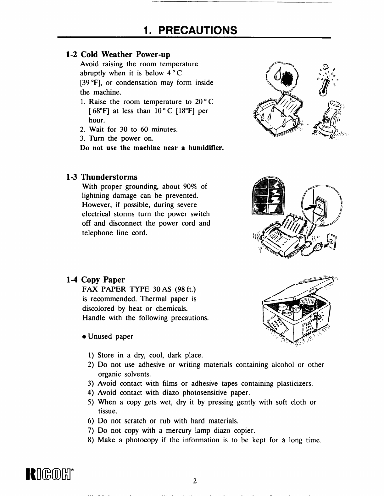
1-2
Cold Weather Power-up
Avoid raising the room temperature
abruptly when it is below 40 C
[39 ‘F], or condensation may form inside
the machine.
1. Raise the room temperature to 200 C
[ (i&F] at less than 100 C [18°F] per
hour.
2. Wait for 30 to 60 minutes.
3. Turn the power on.
Do not use the machine near a humidifier.
1-3
Thunderstorms
With proper grounding, about 90% of
lightning damage can be prevented.
However, if possible, during severe
electrical storms turn the power switch
off and disconnect the power cord and
telephone line cord.
6
(!@
Q
,i//pfi/.”~’
r>
“Q$J’’$$!J:Y
x+
.@ ,
S.%*O
.-
@o’---
c
8
(Ql, ,
8
t.
1-4 Copy Paper
FAX PAPER TYPE 30 AS (98 ft.)
is recommended. Thermal paper is
discolored by heat or chemicals.
Handle with the following precautions.
● Unused paper
1)
Store in a dry, cool, dark place.
Do not use adhesive or writing materials containing alcohol or other
2)
organic solvents.
Avoid contact with films or adhesive tapes containing plasticizers.
3)
Avoid contact with diazo photosensitive paper.
4)
When a copy gets wet, dry it by pressing gently with soft cloth or
5)
tissue.
Do not scratch or rub with hard materials.
6)
Do not copy with a mercury lamp diazo copier.
7)
Make a photocopy if the information is to be kept for
8)
a long time.
Rmml”
2
Page 9
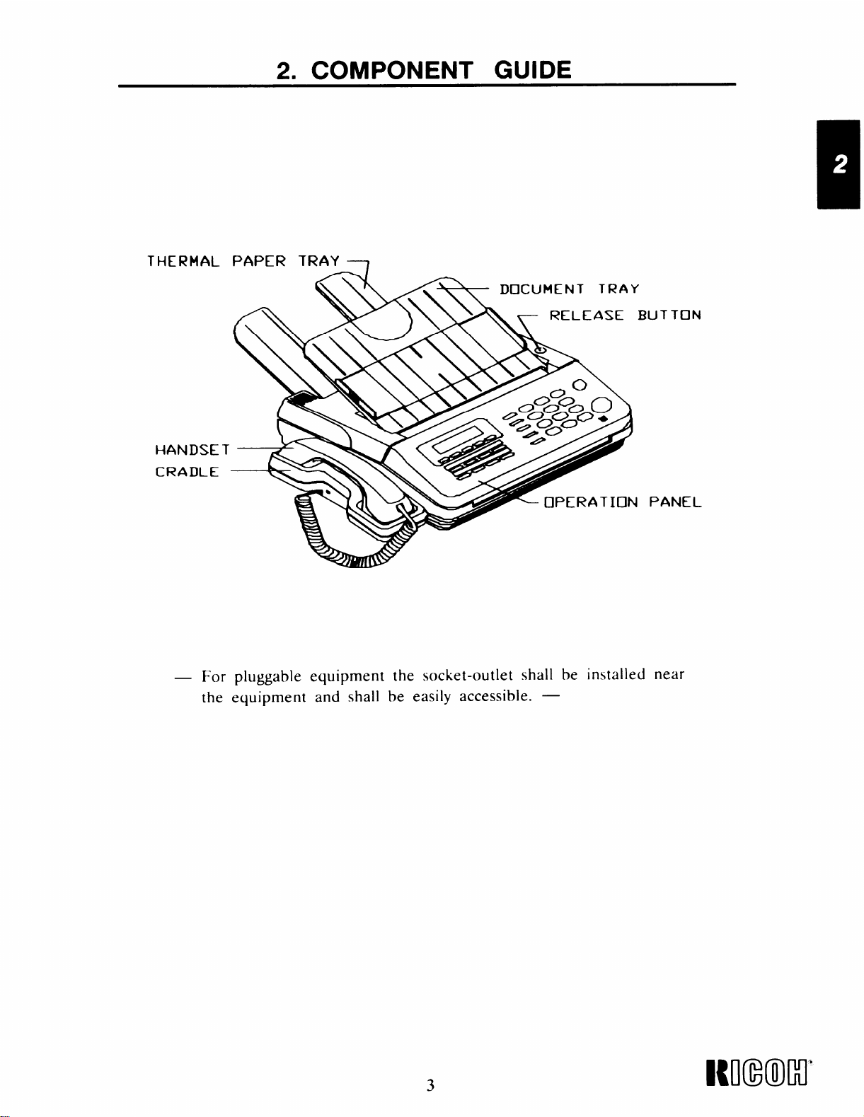
2. COMPONENT GUIDE
THERMAL PAPER TRAY ~
DOCUMENT
\
TRAY
ASE BUTTON
For pluggable equipment the socket-outlet shall be installed near
the equipment and shall be easily accessible. —
3
Page 10
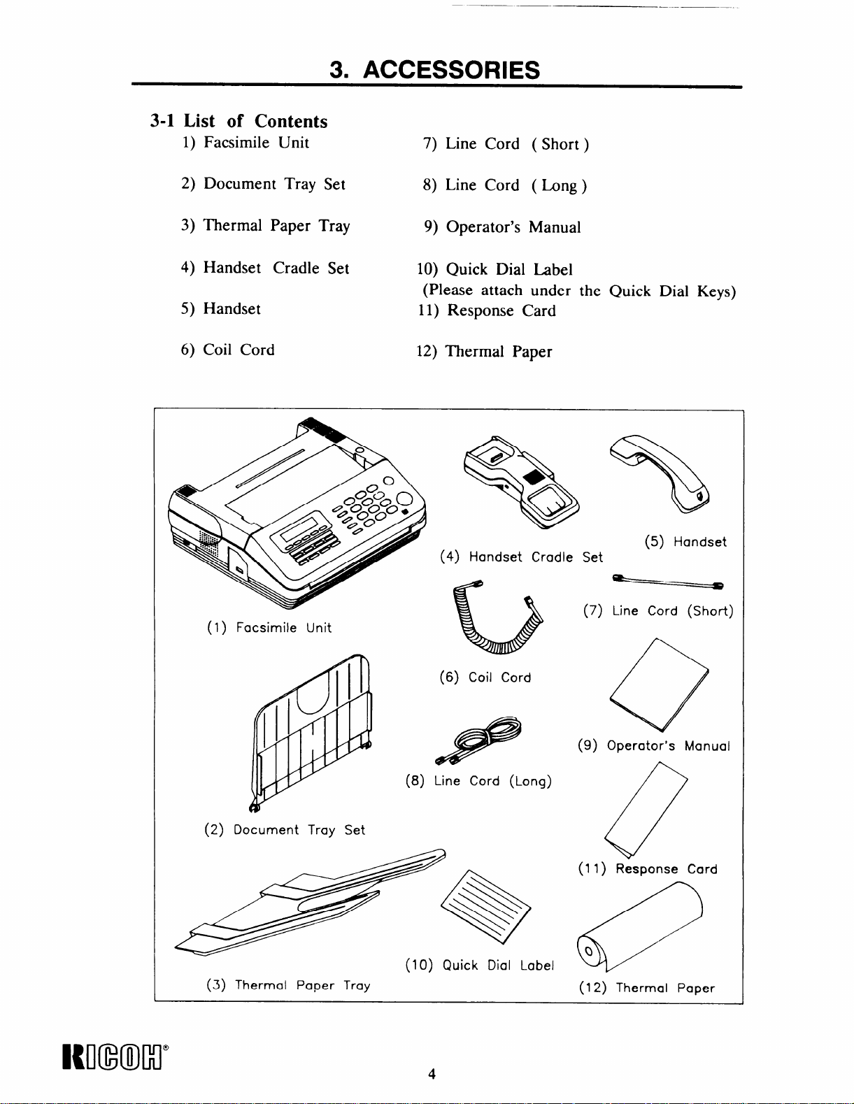
3-1 List of Contents
1) Facsimile Unit
3. ACCESSORIES
7) Line Cord ( Short)
2) Document Tray Set
3) Thermal Paper Tray
4) Handset Cradle Set
5) Handset
6) Coil Cord
8) Line Cord ( Long)
9) Operator’s Manual
10) Quick Dial Label
(Please attach under the Quick Dial Keys)
11) Response Card
12) Thermal Paper
@
☞
●
Q
%
{
/
/
P
(4) Handset Cradle Set
(5) Handset
(1) Facsimile Unit
w
(2) Document Tray Set
(3) Thermal Paper Tray
b
(6) Coil Cord
e
(8) Line Cord (Long)
(10) Quick Dial Label
(7) Line Cord (Short)
o
(9) O~erator’s Manual
. .
(11 ) Response Card
(12) Thermal Paper
Itll(mclr
4
Page 11
3. ACCESSORIES
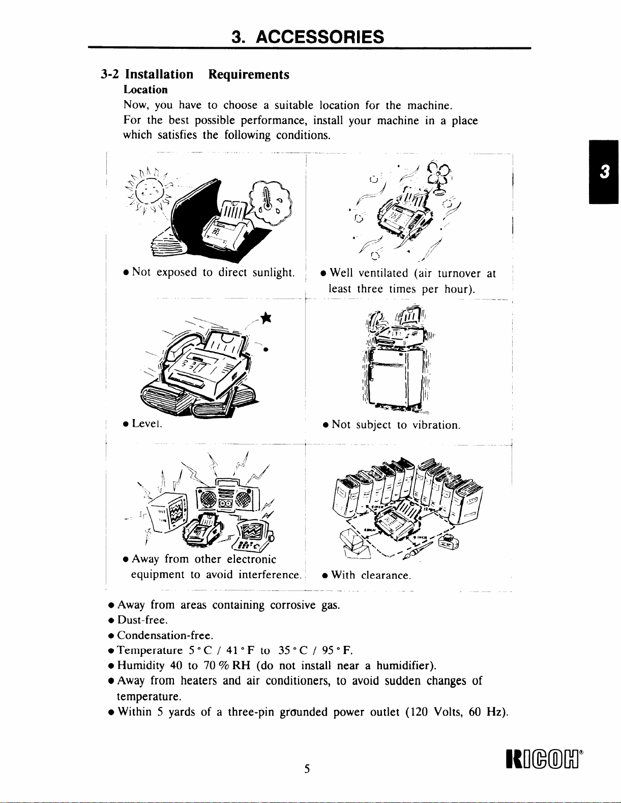
3-2 Installation Requirements
Lucation
Now, you have to choose a suitable location for the machine.
For the best possible performance, install your machine in a place
which satisfies the following conditions.
—
.-
‘ ,/ (jo$
~(;>~~,.~’
:-~+,
●Not exposed to direct sunlight.
b
/--
c
*6 ~)
f<-
Well ventilated (air turnover
●
least three times per hour).
t
4
K’>-=.. , “,
./’
:-T#/
at
● Level.
—-
.Away from other electr~nic
equipment to avoid interference. ,
—
● Away from areas containing corrosive gas.
● Dust-free.
● Condensation-free.
.Temperature 5°C/410F to 35° C/ 950F.
● Humidity 40 to 70 % RH (do not install near a humidifier).
● Away from heaters and air conditioners, to avoid sudden changes of
temperature.
● Within 5 yards of a three-pin grcnmded power outlet (120 Volts, 60 Hz).
—.—— __
● Not subject to vibration.
1
● With clearance.
----4
—
Wl(mcl”
Page 12
———
3. ACCESSORIES
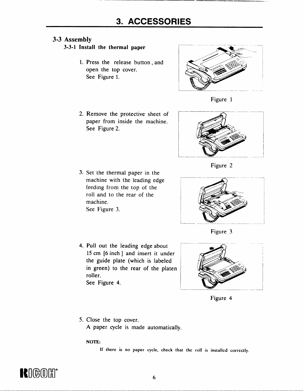
3-3 Assembly
3-3-1 Install the thermal paper
1. Press the release button, and
open the top cover.
See Figure 1.
2. Remove the protective sheet of
paper from inside the machine.
See Figure 2.
Figure 1
3. Set the thermal paper in the
machine with the leading edge
feeding from the top of the
roll and to the rear of the
machine.
See Figure 3.
4.
Pull out the leading edge about
15 cm [6 inch ] and insert it under
the guide plate (which is labeled
in green) to the rear of the platen
roller.
See Figure 4.
Figure 2
~——- n “ ‘-–-–—
— -—
Figure
.—
Figure 4
3
————
I
Icmxml”
5. Close the top cover.
A paper cycle is made automatically.
NOTE:
If there is no paper cycle, check that the roll is installed correctly.
Page 13
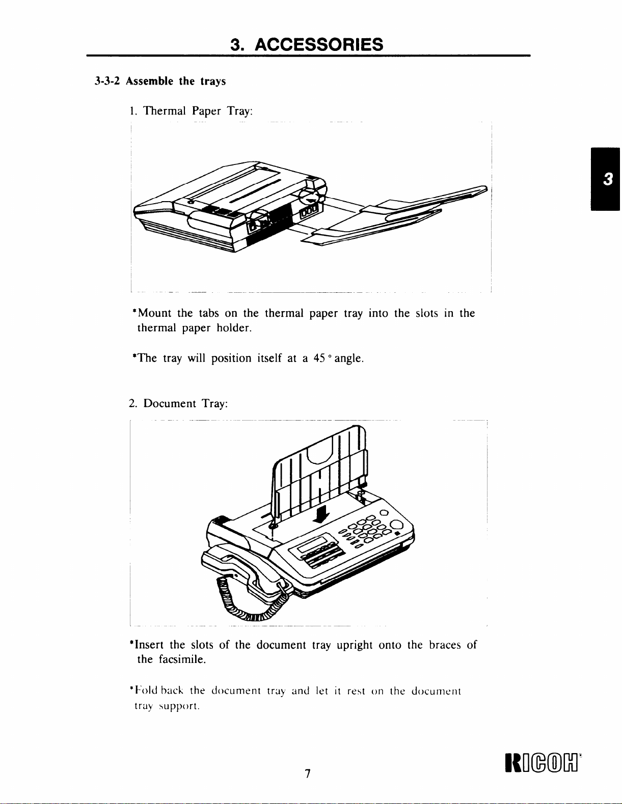
3-3-2 Assemble the trays
1. Thermal Paper Tray:
— —
*Mount the tabs on the thermal paper tray into the slots in the
thermal paper holder.
3. ACCESSORIES
*The tray will position itself at a 45 °angle.
2. Document Tray:
— .—
I
“Insert the slots of the document tray upright onto the braces of
the facsimile.
—.
i
*Fold back the
tray support.
c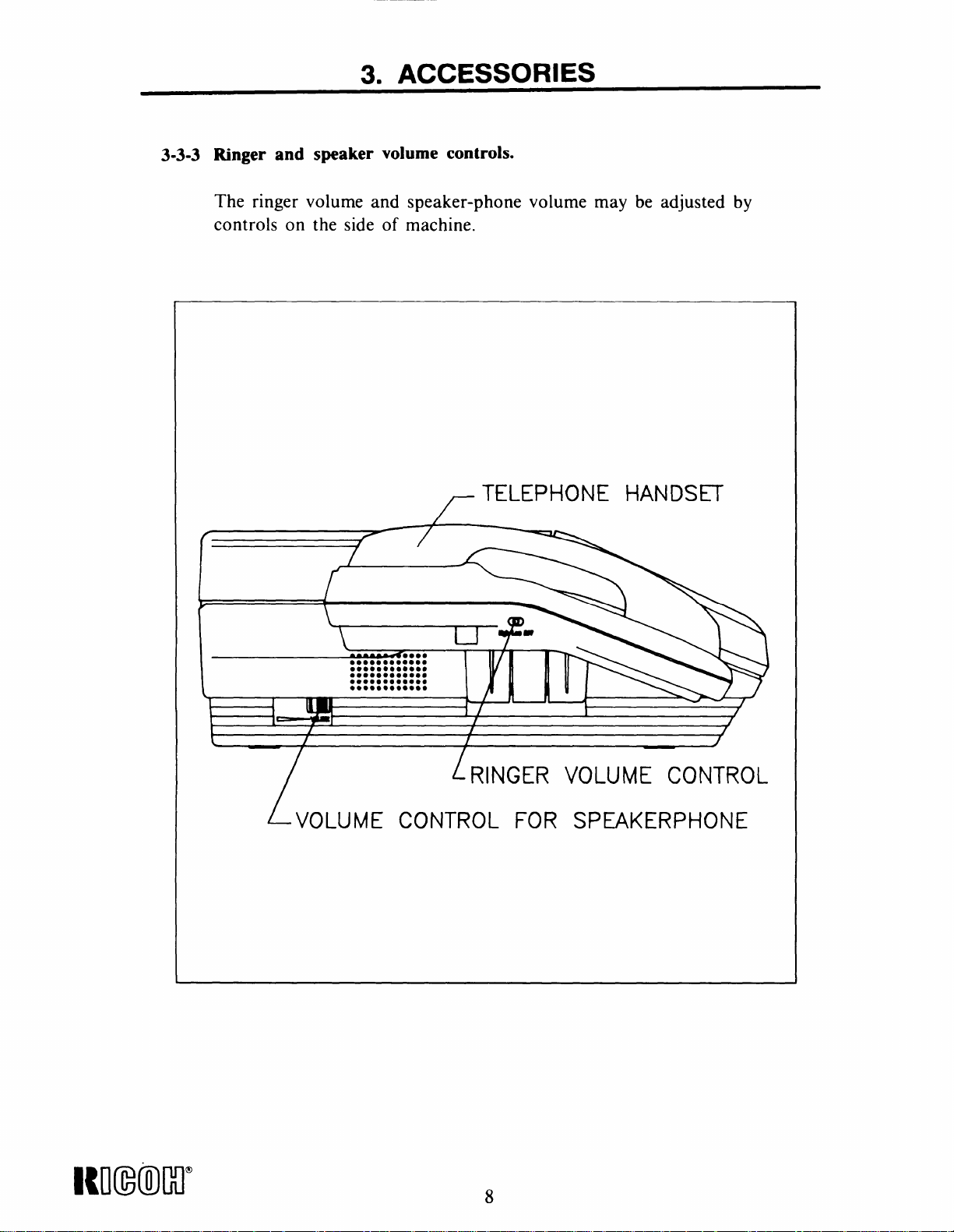
3. ACCESSORIES
3-3-3 Ringer and speaker volume controls.
The ringer volume and speaker-phone volume may be adjusted by
controls on the side of machine.
TELEPHONE HANDSET
f
k
\
L.-M
L-voLUME cofqTRoL FOR sp~KERpl+oNE
[
T
RINGER VOLUME CONTROL
Nl(mlcl”
Page 15

3. ACCESSORIES
3-3-4 Connect the power cord and the telephone line – Refer to section 1-1
● Connecting the power cord
Make sure that the power switch on the rear of the machine is turned
off, then connect the power cord to an AC wall outlet as shown below.
NOTE
1. Avoid using the same AC wall outlet for this unit and other
equipment.
2. Avoid comecting the same line for this unit and another telephone or
facsimile unit. However, you can connect an another telephone set to
the rear of the machine.
Use a dedicated three pin grounded wall outlet,
I
POWER SWITCH
CONNECT THE LONG MODUIJ4R
CORD TO THE LINE JACK
AND THE OTHER END TO A STANDAR[
TELEPHONE LINE JACK (PSTN)
MODUIAR RJ1 lC JACK
POWER CORD
J
i
o
n
u
ANSWERING MACHINE
I
CONNECT THE SHORT LINE
CORD TO THE BACK OF
THE BASE OF lHE TELEPHONE
AND TO THE PHONE JACK
I
CONNECT YOUR ANSWERING
- MACHINE OR AN EXTERNAL
TELEPHONE TO THE ANS JACK
9
I{mmr
Page 16
4. OPERATION PANEL
1 679 8 13
*
-
F
1
4
2
3 10
1211
@@@
‘%!! ),
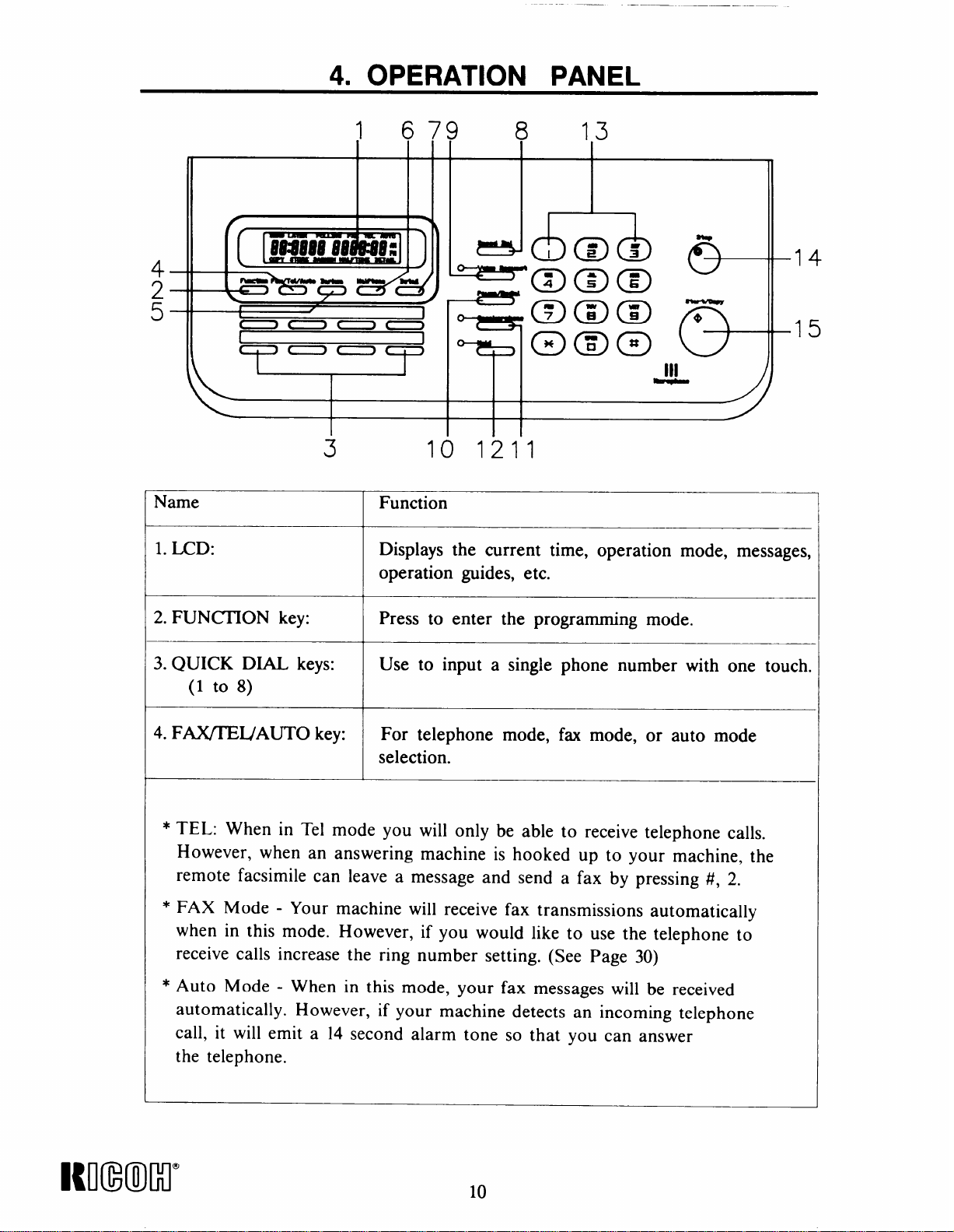
Name Function
1. LCD: Displays the current time, operation mode, messages,
operation guides, etc.
2. FUNCHON key: Press to enter the programming mode.
3. QUICK DIAL keys: Use to input a single phone number with one touch.
(1 to 8)
4. F~IJAUTO key:
For telephone mode, fax mode, or auto mode
selection.
5
‘
* TEL: When in Tel mode you will only be able to receive telephone calls.
However, when an answering machine is hooked up to your machine, the
remote facsimile can leave a message and send a fax by pressing #, 2.
* FAX Mode - Your machine will receive fax transmissions automatically
when in this mode. However, if you would like to use the telephone to
receive calls increase the ring number setting. (See Page 30)
* Auto Mode - When in this mode, your fax messages will be received
automatically. However, if your machine detects an incoming telephone
call, it will emit a 14 second alarm tone so that you can answer
the telephone.
Kmm)lll”
I
10
Page 17
4. OPERATION PANEL
‘--1
—-
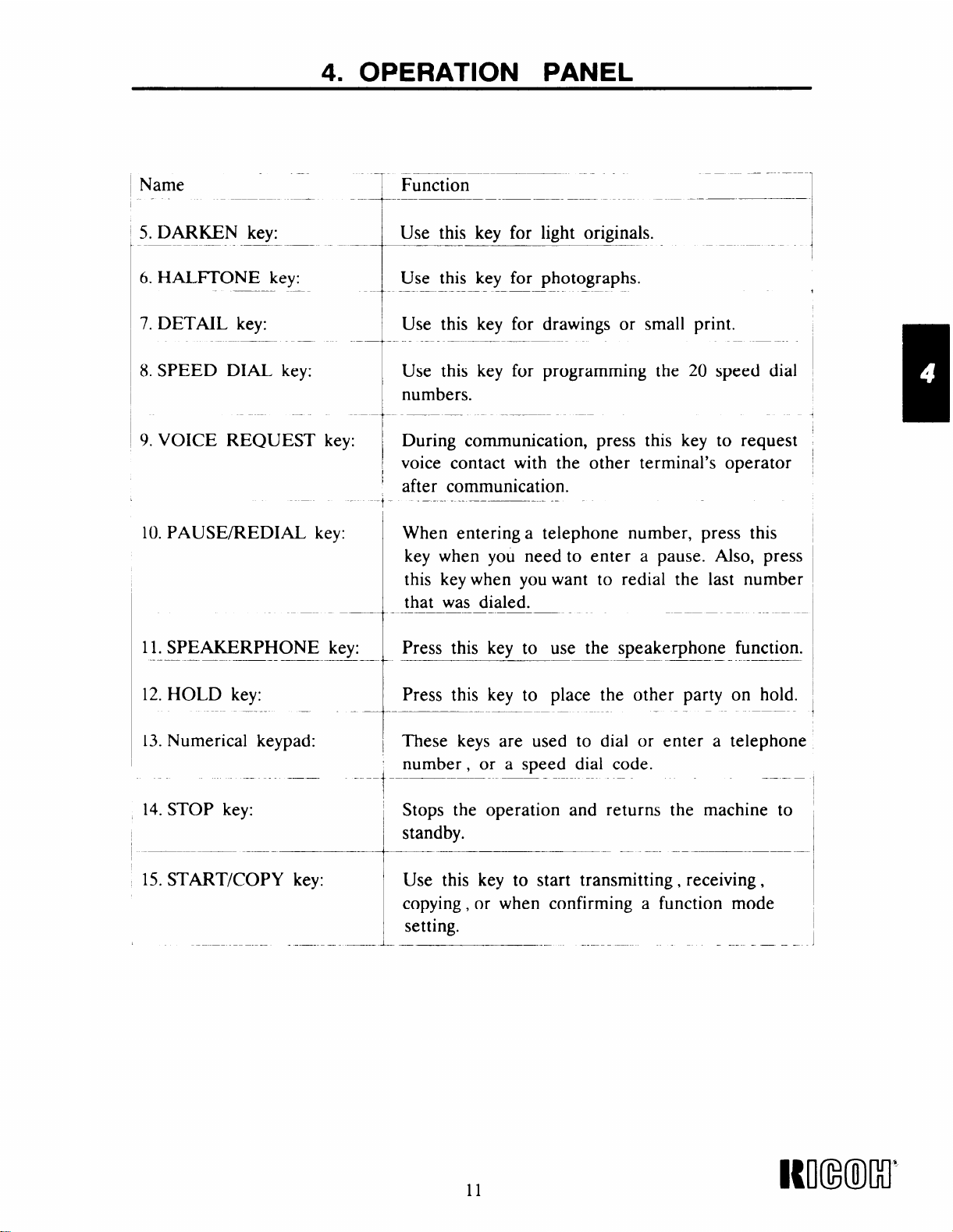
Name
.——
1
Function
—
‘“--’T-
5. DARKEN key:
-+--- ‘-
6. HALITONE key:
Use this key for light originals.
Use this key for photographs.
1-
7. DETAIL key: print.
8. SPEED
9. VOICE
10. PAUSE/REDIAL
——.
DIAL key:
REQUEST During communication, press this key
key:
Use this key for drawings or smal
-A-.....----
Use this key for programming the
numbers.
voice contact with the other terminal’s operator
after communication.
—..-
When entering a telephone number, press this
key when you need to enter a pause. Also, press
this key when you want to redial the last number
that was dialed.
20 speed dial
to request
-
+
—
11. SPEAKERPHONE
——.
12. HOLD key:
13. Numerical keypad:
4. STOP
15. START/COPY key:
key:
Press this key to use the speakerphone function.key:
-- —
——
Press this key to place the other party on hold.
These keys are used to dial or enter a telephone
number , or a speed dial code.
Stops the operation and returns
standby.
Use this key to start transmitting, receiving,
copying, or when confirming a function mode
setting.
— — .—
—
the
—.—
—
machine to
11
Icll(mllo’
Page 18
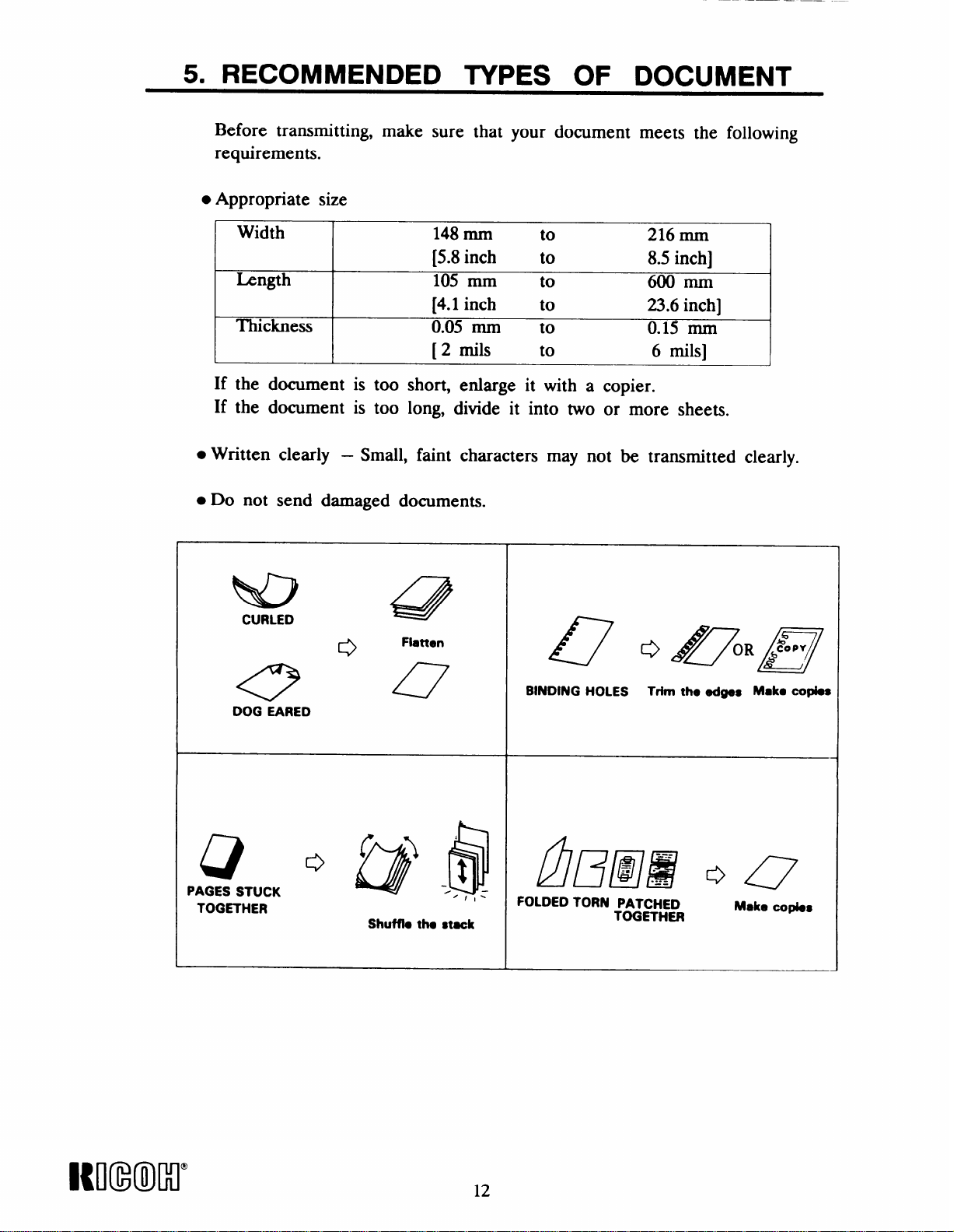
5. RECOMMENDED TYPES OF DOCUMENT
Before transmitting, make sure that your document meets the following
requirements.
● Appropriate size
Width
I
Length 105 mm to
Thickness
[
148 mm to
[5.8inch to
[4.1
inch to
0.05 mm to
[ 2 roils to
216 mm
8.5 inch]
600 mm
23.6 inch]
0.15 mm
6 roils]
J
If the document is too short, enlarge it with a copier.
If the document is too long, divide it into two or more sheets.
● Written clearly – Small, faint characters may not be transmitted clearly.
● Do not send damaged documents.
ND
CURLED
0
47
~
Q o /lfy&l/~
e
DOG EARED
Q
PAGES STUCK
TOGETHER
o @ ./$
Shufflo tho stack
~/l-
BINDING HOLES Trim the edges Mak. copies
fl/~/aj’~ o ~
FOLDED TORN PATCHED
TOGETHER
Make
COfI&S
KNmMl”
12
Page 19
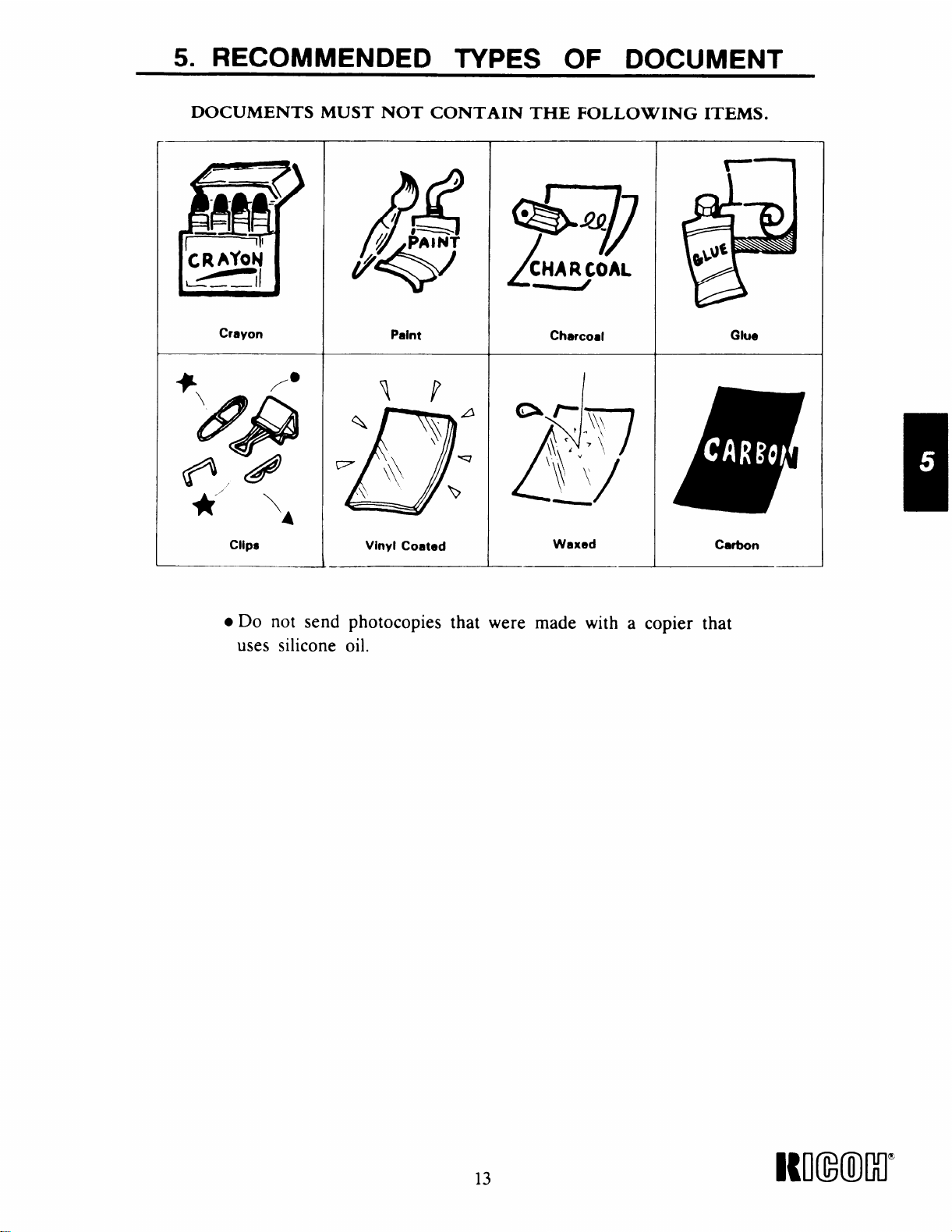
5. RECOMMENDED TYPES OF DOCUMENT
DOCUMENTS MUST NOT CONTAIN THE FOLLOWING ITEMS.
● Do not send photocopies that were made with a copier that
uses silicone oil.
13
Nl(mMr
Page 20
6. ROUTINE OPERATION
Basic Transmission
6-1
Before transmission, refer to page 31 to program your line type (i.e. Pulse
or Tone) and page 32
– Preparation –
to program your transmission terminal identification.
1. Make sure that the
status (the machine
or AUTO mode).
2.
Carefully place the document(s) into the feeder face down along the
guide.
● Do not insert more than 10 pages at once.
● Loosen any pages stuck together.
● Align the leading edges.
● Adjust the guide to the document width.
● Transmit sheets of different width separately.
NOTE:
1. Refer to page 12 and 13 to make sure that your document is suitable for use.
2. Documents may also be fed in manually, one at a time.
During transmission, the next sheet must be placed in the feeder.
3.
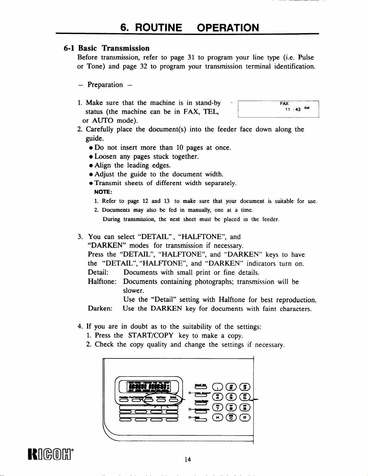
You can select “DETAIL”, “HALITONE”, and
“DARKEN” modes for transmission if necessary.
Press the “DETAIL”,
the “DETAIL”, “HALFI’ONE”, and “DARKEN” indicators turn on.
Detail: Documents with small print or fine details.
Halftone: Documents containing photographs; transmission will be
slower.
Use the “Detail” setting with Halftone for best reproduction.
Darken:
Use the DARKEN key for documents with faint characters.
machine is in stand-by can be in FAX, TEL
“HALITONE”, and “DARKEN” keys to have
~
4.
Itmxml”
If you are in doubt as to the suitability of the settings:
1. Press the START/COPY key to make a copy.
2. Check the copy quality and change the settings if necessary.
1
14
Page 21

– Procedure –
6. ROUTINE OPERATION
The display should now be as shown on the right.
DARKEN, HALFI’ONE and DETAIL will show
in the display if selected.
DARKEN HAIHONE DETAIL
L
1. Enter the phone number of the remote terminal
using either a:
. Quick Dial key
● Speed dial code (from 01 to 20)
● Full telephone number (keypad on panel)
Only one destination can be entered.
To correct any mistakes, press the STOP key.
Quick Dial key:
1) Press the desired QUICK DIAL key (e.g., Ol)J__–– FM
See page 40 for details on how to store-
L
Quick Dial keys.
Then press the “START/COPY” key if the
2)
keyed-in number is correct.
The message will now be transmitted.
FAX
8
5551212
–1
18m
1
J
Speed Dial code:
1)
Press the SPEED DIAL key
2)
Then enter the required two-digit speed-dial
code (e.g., 13) at the numerical keypad.
Refer to page 41 for details on how to store
Speed Dial numbers.
Then press the “START/COPY” key if the
3)
keyed-in number is correct.
The message will now be transmitted.
J
L
15
Nl(mllxlm
Page 22

6. ROUTINE OPERATION
Full Telephone Number at the Keypad:
1)
Enter the remote terminal telephone number
(e.g., 5551212 ) on the operation panel while
keeping the handset on-hook.
2)
Then press the
keyed-in number is correct.
The message will now be transmitted.
Full Telephone Number at the External Telephone:
“START/COPY” key if the
~
1) Dial the remote terminal telephone number
(e.g., 5551212 ) on the external telephone.
2) Then press the
you hear a high-pitched tone.
The message will now be transmitted.
NOTES:
1. If you dialed the wrong number, press the “STOP” key to cancel the
operation and restore the machine to stand-by mode.
2. If an error happens during transmission, the LCD
will display the error code as shown on the right.
“START/COPY” key when
w!!!!
IUI(INMI”
16
Page 23

6. ROUTINE OPERATION
Notes Concerning Transmission:
● Transmission during telephone conversation
1)
During telephone conversation, using
the built-in handset, the display is as
shown on the right, showing the length
of the conversation.
Now insert your document into the feeder.
2)
Then press the “START/COPY” key.
3)
Make sure that the other party presses
Start after you press START/COPY.
Hang up when you hear a high-pitched
tone.
r
: 0021
I
L
555
Fii
FAX
1143
(Called party sends CSI)
J
J
4)
The message will now be transmitted.
5) When communication is finished, standby mode
will be restored automatically.
● Auto-redial:
[
If the line is busy or contact is impossible, the number is automatically
redialed up to 10 times at intervals of about 3 minutes.
To cancel redialing, remove the document from the feeder as explained
in section 10-1.
NOTE:
can redial immediately by pressing PAUSE/REDIAL if required,
YOU
FAX
8 25 ‘M
● Error Report
If transmission fails, an Error Report will be printed.
Keep this, it may help the service technician.
Error codes are explained on pagq 47.
17
WmM1’
Page 24

6. ROUTINE OPERATION
6-2 Reception
–
Automatic Reception –
This machine will receive documents unattended if
a) The power switch is on.
b) The FAX/I’EIJAUTO setting is at AUTO or FAX mode.
– Manual Reception –
When the machine is in the “TEL” (manual) mode, reception
accomplished by one of the following procedures:
1. -
Phone rings.
Pick up the handset.
Establish voice contact with the calling side.
When the calling side is ready to transmit to you, remove any
documents from the document feeder and press the “START/COPY”
key. (The calling party should press
hearing the high pitched tones from your machine.)
Reception will begin.
Hang up the handset.
their “START/COPY” key after
can be
Phone rings.
2. -
Pick up the handset.
A short tone can be heard every 3 to 5 seconds.
(This indicates that a facsimile terminal is calling.)
Remove any documents from the document feeder.
Then press the START/COPY key.
Reception will begin.
Hang up the handset.
If you share the fax line with a telephone and if you receive a lot of
telephone calls on that line, you should switch the machine to TEL mode,
or enter a high value for the ring number (see page 30).
If you switch to AUTO mode or FAX mode, you will
answer telephone calls unless you have entered a high
not be able to
value for the
ring number.
NOTE:
1. If a message comes in while you are making a copy, press the STOP key ,
remove the documents from the feeder, then press the START/COPY key
to receive the message.
2. If reception fails, an Error Report will be printed. Keep this; it may help
the service technician. Error codes are explained on page 47.
18
Page 25

6. ROUTINE OPERATION
Receiving during telephone conversation
During telephone conversation, just press the “START/COPY” key
if you want to receive the document.
– Procedure –
1. During telephone conversation,
the LCD will be as shown on the right.
0021
2. Remove any document from the document
feeder.
3. Press the “START/COPY” key and wait
for the document . (The other party must press the START key at
their end.)
Then hang up the handset.
FAX
4. After receiving is completed,
the LCD will return to standby mode.
6-3 Ringing Telephone and Buzzers
–
Single Ring –
A message is coming in.
(if your machine is in FAX or AUTO mode).
Do not pick up the handset or the telephone.
– Continuous Ringing –
If TEL mode is not indicated, and the ring number (see page 30)
has expired, either:
1)
Power is switched off (the external telephone will ring).
2)
The other party requires voice contact.
(The internal buzzer will sound)
Pick up the handset, and speak.
Refer to “VOICE REQUEST” on page 26.
If
TEL mode is indicated:
A message is coming in.
● Pick up the handset and speak to the caller.
NOTE:
If the calling terminal is in automatic dialing mode,
you will not be able to speak to the caller.
You will hear intermittent tones.
Remove any document from the document feeder.
Press the START/COPY key during the initial intermittent tones.
● Remove any document from the document feeder.
● Press the START/COPY key after speaking , to receive
the incoming messages.
● When the line is connected, hang up.
It will be received automatically
FAX
8 25 ‘M
19
Page 26

..
6. ROUTINE OPERATION
6-4 Replacing the Thermal Paper
1.
Press the release button, and open
the top cover.
See Figure 4.
2. Take out the empty roll and install
a new one with the leading edge at
the top of the roll and facing the
rear of the machine.
See Figure 5.
3. Pull out the
[6 inch] and
plate (which
rear of the platen roller.
See Figure 6.
leading edge about 15 cm
insert it under the guide
is labeled in green) to the
Figure 4
J
Figure 5
Nl(mm”
klgure b
4. Close the top cover.
A paper cycle is made automatically.
NOTE
If there is no paper cycle, check that the roll is installed correctly.
20
Page 27

6. ROUTINE OPERATION
6-5 Daily Care
If the room is cold, refer to “Cold Weather Power-Up” on page 2
before switching on.
1.
Check the LCD. If there is any error code displayed, correct
the fault.
2.
Place a document in the feeder and press the START/COPY key.
Check that the copy quality is, satisfactory.
Open the printer and remove
3.
Gently wipe the thermal head
cloth moistened with alcohol.
NOTE:
Do not use water
—
r-
the roll.
and the guide plate with a clean soft
Thermal
Head
4. Clean the machine’s exterior with a
Do not use a cleaning agent.
—
clean soft dry cloth.
—
21
Itoumr
Page 28

Polling
7-1
7-1-1 Polling Reception
This feature allows you to call a remote terminal and instruct it to
send you whatever documents it has stored in polling standby for you
to pick up.
7. SPECIAL
FEATURES
NOTE: There must be a message on polling standby at the other
– Procedure –
1) In standby mode, the LCD will display:
2) Press the FUNCHON key, then press “ 1“ .
The LCD will display “POLLING”.
3) Then dial the phone number for polling
reception.
4) Press the START/COPY key to instruct
the machine to start polling reception.
~
POLLING FAX
[
end.
FAX
8:33 ‘M
5551212
Im(m”
5) The LCD will return to standby mode
after finishing polling reception.
6) If you want to cancel Polling Reception,
press STOP key, and the machine will
return to standby mode.
22
Page 29

7. SPECIAL
FEATURES
7-1-2
Polling Transmission
This feature allows you to leave a document in the feeder for a remote
terminal to pick
mode. Reception
NOTE: Anyone ean
for sending
—
Procedure –
1)
Place the documents into the feeder for Dollirw r–
up. This
can take
poll your
confidential messages.
will place your terminal in polling standby
place as normal in polling standby mode.
terminal, so
do not use this feature
transmission.
~... —.——,
2)
Press the
The LCD
FUNCT’ION key, then press “l“.
will display “POLLING”.
POLLING FAX
FAX
7
8:23 ‘M
3) Your terminal is now in polling standby mode.
When your terminal is polled, it will scan and
transmit the document.
4) To cancel polling standby mode, press the
STOP key.
POLLING FAX
8:23 ‘M
1
23
Page 30

7. SPECIAL
FEATURES
If you want to have a voice
—
Procedure –
1)
Press the VOICE REQUEST key during polling
communication during polling transmLwionJreception
transmission / reception.
VOICE REQUEST indicator will turn on.
The
2) When polling transmission/ reception is finished,
the machine will make a sound to announce a voice
request. (Bursts of short beeps will be heard ‘–
until you pick up the handset.)
3) Now pick up the handset and speak.
POLLING FAX
1
00:21
POLLING FAX
[
8:26 ‘M
-1
4) Replace the handset after speaking.
NOTE:
If your machine does not emit a tone, the remote terminal operator did not come
to the phone.
The line will be disconnected automatically.
WmMr
24
Page 31

7. SPECIAL FEATURES
7-2 Send Later Transmission
This feature delays transmission until a time selected by the operator.
This feature can be used to take advantage of off-peak line charges.
The designated time must be within 24 hours of entry.
– Procedure –
1)
Select the contrast and resolution.
Then press the FUNCT’ION key.
2)
Press 2 at the keypad.
The LCD will be changed as shown on the
right. (DARKEN, HALFI’ONE and DETAIL
will only show up if selected.)
3)
Place the document into the feeder.
SEND tiTER - FAX
-1
—
AM
1
4)
Enter the required transmission time. ‘ SEND LAYHT Fm -
Then press # to change from AM to PM, ~
or press ● to change from PM to AM.
For example: To set 8:25 PM, enter “0825 #“.
5) Then press the VOICE REQUEST key.
SEND
IATER- FM”
[
Enter the desired destination fax number by Ex:
6)
using
or fu
7) Press
time and
8) Press the
a QUICK DIAL key, Speed Dial code, ~~~ ~ flE~-6 ~F~
I telephone number at the keypad.
START/COPY key to confirm the
the
telephone number setting.
SENb
IATER FAX
8 25P 8 22 ‘M
STOP key if you want to return ~
to standby mode.
08 25m
FAX
8:23 ‘M
I
I
)
1
I
,
Cancel Send Later Transmission –
–
1) Press the Stop
when you want
key or tak~ out the document,
to cancel the send later function.
25
I{mxml”
Page 32

Voice Request
7-3
With this feature, you can speak with the remote terminal operator
after transmission or reception.
For Voice Request to be effective, both terminals must:
● Have a telephone or handset connected.
● Have the voice request function.
To talk with the remote terminal operator at the end of
communication, do the following.
If you are transmitting
1)
Press the VOICE REQUEST key during transmission.
2)
When your machine sounds a tone after transmitting,
pick up the handset, then speak.
Replace the handset after speaking.
3)
If
you are receiving
1)
Press the VOICE REQUEST key during reception.
When your machine sounds a tone after receiving,
2)
pick up the handset and speak.
Replace the handset after speaking.
3)
NOTE:
1. If your machine
not come to the
2. When you press
does not emit a tone, the remote terminal operator did
phone. The line will disconnect automatically.
the VOICE REQUEST key, the indicator will be
lit.
NImKr
26
Page 33

7. SPECIAL
FEATURES
7-4 Immediate Redial
When the remote terminal is busy, the machine will automatically
redial after about 3 minutes. However, you can make an immediate
redial by pressing the PAUSE / REDIAL key. This function is also
available when the machine is in standby mode.
– Procedure –
Either:
1) Keep the handset on-hook.
Then place the document into the feeder.
2) Press the PAUSE/ REDIAL key.
3) Then press the START/COPY key.
4) Redialing starts immediately.
Or:
1) Pick up the handset.
2) Press the PAUSE/REDIAL key.
3) Then press the START/COPY key
NOTE:
If the line is still busy, you can cancel any further redialing and
return to standby mode by pressing the STOP key.
27
I{mximl’
Page 34

8. FUNCTIONS AND PROGRAMMING
This machine has a wide range of programmable ,functions. Study these
functions to get the most out of the machine. To program these hmctions
the machine must be in standby mode. If you want to return the machine
to standby mode at any time while programming, press the STOP key
or pick up the handset.
NOTE:
1. All programmed items remain in memory even if you switch the power off.
2. All programmed items have a time-out limit (1 minute). If there is no key
input after 1 minute, the machine will return to standby mode.
n
L___you will be using these keys to program
the various features in
functions are as follows:
Item
F 01
F02
F 03
>
1------
F04
F 05
F06
F 07
F 08
F09
Description
PRINTING THE TCR
RING NUMBER SETTING
TELEPHONE LINE TYPE SE?TING
TELEPHONE NUMBER SETTING (CSI)
NAME/ LOGO SETT’ING (Tll)
DISABLE T1’I FUNCTION SE’ITING
PRINTING THE TELEPHONE LIST
CLOCK ADJUSTMENT
PRINTING THE FUNCI’ION LIST
L_-
—
the machine .
—
.—
—.
-1
I
I
-1
I
—1
‘-
-1
I
J
INI(NMI”
28
Page 35

8. FUNCTIONS AND PROGRAMMING
8-1 Printing the TCR – F 01
This report gives details on each communication made by your terminal.
It is automatically output every S0 communications. However, you can
print a copy of this report by doing the following.
Format of the TCR
—
****** T C R ******
● **************** ● **************** ***************** ***************** ● ********
●MODE REMOTE TERMINAL I.D. START TIME
● ______ _________________ ________ ------------ _______ _______ ________ ●
●-TX
I*
1
I
I*2 7761352
I*
*
●
1
● **************** ***************** ***************** ***************** ● ********
L
STOP––
*
00188628823131
RX
1 7761987
–The “STOP” key was pressed while communication
03/0310:03AM
03/0611:45AM
03/0311:20AM
MAR 07 ’90
TIME PAGES STATUS
00:27 1 G3S ●
00:08 **
00:35 1
4 *
08:18 AM
STOP
G3D *
was in progress.
* G3 S –– –G3 Protocol & Standard resolution.
● G3D–– –G3 Protocol & Detail resolution.
—
Procedure –
1)
Press FUNCI’ION, then press “3”.
F(3I
I
L.
FAX- -
8:17 ‘Ml
●
●
●
●
J
2) Press the START/COPY key.
The TCR Report will be printed.
3) After printing is finished,
the LCD will return to standby mode.
4) The printing will stop if either the handset
is picked up or the STOP key is pressed
during printing.
29
FAX
r---
8:20 ‘M
L- _____________ 1
Ml(mlw
Page 36

8. FUNCTIONS AND PROGRAMMING
8-2 Setting the Ring Number – F 02
This feature provides an alternative selection for the number of rings
that the machine emits before it automatically answers the line.
The programmable ring number can be set from 1 to 9, depending
upon the user’s preference. A higher value gives the user a chance to
answer the phone personally, even if the machine is in Fax mode or
Auto mode. This setting does not affect the way that the machine
operates in TEL mode. In TEL mode, the machine never answers
the line automatically unless attached to an answering machine (see
page 42).
—
Procedure –
.—
Press FUNCI’ION, then press “3”.
1)
The LCD will display “F 01”.
2)
Press the DETAIL key once to access
F 02.
NOTE:
The LCD will show the current setting.
Enter the desired ring number.
3)
(1 to 9)
For example: 5 rings.
Press “5” on the keypad.
Then press the
4)
program in the
START / COPY key to
setting and access F 03.
~
~
ETcl
Imxml”
Press the STOP
5)
standby mode.
key if you wish to return to
30
Page 37

8. FUNCTIONS AND PROGRAMMING
8-3 Telephone Line Type Setting – F 03
This feature lets the user select the dialing mode of the operation
panel’s ten-key pad. The type of dialing used by the machine must
be the right type for your local telephone exchange, or your terminal
may not be able to place calls.
dialing, and tone dialing. The initial status on the LCD is “OO“ for
TONE mode. But you can enter “O 1“ to change to PULSE mode
from TONE mode.
—
Procedure –
1)
Press FUNCI’ION, then press “3”.
The LCD will display “ F 01”.
2)
Press the DETAIL key 2 times to access - – FM
F 03.
There are two dialing modes: pulse
—
FO1
FAX
r
F03 00
r
I I
8 18 ‘M
1
1
Enter “1“ to change to PULSE mode,
3)
if it is necessary. Or, press ‘O’ to change
back to TONE mode.
4) Then press the START/ COPY key to
program in the setting and access F 04. -- — ‘-—–’-
5) Press the STOP key if you wish to return to
standby mode.
NOTE:
If your machine cannot dial, change this setting.
F03 01
F04 01 90
[“-
Fti
FAX
J
31
Immcl’
Page 38

8. FUNCTIONS AND PROGRAMMING
8-4 TTI – Transmission Terminal Identification
The TI’I consists of your fax machine’s telephone number (use F 04)
and the name of who you are as the sender (use F 05). When you send
a fax message, the machine at the other end prints your lTI at the top
of each page. The telephone number (programmed with F 04) also
appears on the other terminal’s LCD during communication. When you
enter the TT’1, refer to the following table.
Character Code Character Code
o 00
11 1o11
2
3 03 w
4
5 05
6 06 z
7 07 a 38
1
9
space
A 12 f 43
B
c
I
D 15
E 16
I
F
I
H 19 m
I
I
J
K
L 23
M 24
N 25
o 26
P
Q
R
s
02
04
08
I
09 c
10
11
1131
I I I
14 i 45
I
17 k 48
18
I
20
21
I
1
22
!
1
27
I
28 v
29 w 60
30
I
T
u I 32
v
x
Y
b
I
d
e
i
i
a
m
I
I
m
1
!
I
I
1
n 51
o
P
a 54
1
r
s
t
u
x
I
I 44
I
I
I 52
[
I
,
I
I 61
31
33
34
35
36
37
39
40
41
42
46
47
49
50
53
55
56
57
58
59
Character I Code
+----+%
!
!1
#
$
+ 74 -
9
;
.
. 78
<
=
>
?
\
@
{
I
I
I 87
I
64
65
66
67
75
76
77
79
80
81
82
85
86
88 _
89
I{NNMI”
32
Page 39

8. FUNCTIONS AND PROGRAMMING
8-4-1 Telephone Number Setting – F 04
This feature allows you to enter your own telephone number
as a means of communication recognition. Another name for this
is CSI or Called Subscriber Identification. The maximum allowable
length is 20 characters. Any character entry over 20 will scroll to
the first character.
For example: to save 201 555 1234
Setting code Character Order of character
01 02
02 00
03 01
04 10
05 05
06 05
07 05
08 01
09 02
10 03
11 04
2
0
1
space
5
5
5
1
2
3
4
—
1st
2nd
3rd
4th
5th
6th
7th
8th
9th
10th
llth
– Procedure –
1) Press FUNCI’ION, then press “3”.
The LCD will display “F 01”.
2) Press the DETAIL key 3 times to access
F 04.
3) Use the numerical keypad to select the
code related to the first character.
The first character should be “2”.
The code for 2 is “02”.
So, press
“0”, then “2”.
The display should be as shown on the
right.
0 1 means the first figure.
2 is the related code corresponding ~ F O‘$
0
to the first figure “2”.
NOTE:
Only characters O, 1, 2, ....9. space, + (refer to the ml
table) can be set using this function.
r-
1
FO1
F 04
TAX
FAX
TAX
8 17 ‘M
01 90
—
1
01 02
33
Kmml=
Page 40

—
8. FUNCTIONS AND PROGRAMMING
4)
Then press the VOICE REQUEST key
to go to the second character.
The second character should be “O’.
The code for O is “00”.
So press “O” twice.
The display should be as shown onthe right.
O 2 means the second figure.
O 0 is the related code corresponding
to the second figure “O’.
Repeat steps 3) and 4) to enter the required telephone
5)
number.
F3
cm
Then press the START/COPY key to
6)
program in the setting and access F 05.
7) Press the STOP key if you wish to return
to standby mode.
842 Name / Logo Setting – F 05
This feature allows you to enter your own name or company
name or logo to identify yourself to the other party. Another
name for this is your TT’I or Transmit Terminal Identification.
The maximum length is 25 characters.
For example: to set RICOH.
Setting code
01 29
02 20
03 14
04 26
05 19
Character
R
I
c
0
H
Order of character
1st
2nd
3rd
4th
5th
Km(m”
34
Page 41

8. FUNCTIONS AND PROGRAMMING
—
Procedure –
1)
Press FUNCTION, then “3”.
The LCD will display “F 01”.
2)
Press the DETAIL key 4 times to access
F 05.
3)
Use the numerical keypad to select the
code related to the first character.
The first character should be “R”.
The code for R is “29”.
So, press
The display should be as shown on the
right.
O 1 means the first character.
2 9 is the related code corresponding
4)
Then press the VOICE REQUEST key
to go to the second character.
The second character should be “I”.
The code for “I” is “20”.
So, press
The display should be as shown on the
right.
O 2 means the second character.
2 0 is the related code corresponding
“2”, then “9”.
to the first character “R”.
“2”, then “O”.
to the second character “I”.
FO1
E----.-
F05 01 90
1--
1--- -- .—— —....
r
F05 0129
FA%
8:17 ‘M’
—_.
‘FiX
Fti-
1-. . . -.-. -.-----J
i—
F05 02 20
L. . .. .
FAX
—
‘-- ‘-- 1
1
J
I
-J
Repeat steps 3) and 4) to enter all the
5)
characters.
Then press the START/COPY key to
6)
program in the setting and access F 06.
7)
Press the STOP key if you wish to return
to standbv mode.
35
—
F06 00 00
r-“
1–– - -––——— J
FAX –
Immw
Page 42

—.—
8. FUNCTIONS AND PROGRAMMING
Disable lTI Function Setting – F 06
8-5
If you turn on TTI, your TI’I and the date, time, and the page
number will be printed at the top of pages at receiving side.
When you turn off TT’1, only the page number will be printed.
—
Procedure –
1)
Press FUNCIION, then press “3”.
The LCD will display “F 01”.
2)
Press the DETAIL key 5 times to access
F 06.
NOTE:
The LCD will show
“ 1111“ means that lTI is enabled.
3) Then enter “O00 O“ to disable TI’I
output.
4) Press the START/COPY key to program
in the setting and access F 07.
5) Press the STOP key if you wish to return 1
to standby mode.
the current setting.
~
~
I I
I
Im(wr
36
Page 43

8. FUNCTIONS AND PROGRAMMING
_——
8-6 Printing the Telephone List – F 07
This function allows the. user to print out a list of telephone
numbers that are stored as One-touch or as Speed Dial numbers.
– Procedure –
___
—
FAX
Fti
818 ‘Ml
FAX
8.18 i
.——
FAX
8 20 ‘M
—
1) Press FUNCI’ION, then “3”.
The LCD will display “F 01”.
2) Press the DETAIL key 6 times to
access F 07.
3) Then press the START/COPY key
to print the telephone list and access
F 08.
4) If you wish to return to standby mode,
press the STOP key.
———
FO1 8:17 ‘M
r
L . . ..—
F07
F08
[
[-
r--
L–--– .— — -J
*** Telephone List ***
*****************
*
Quick Dial List
●
●
M1 :5551212
☛
M3 :5551234
☛
M5 :5554321
☛
M7 :
●
●
☛
●
Speed Dia
●
☛
01 :5553214
●
03 :5552314
●
05:
●
07:
●
09:
●
11:
●
13 :5554444
☛
15 :
☛
17:
●
19:
● ***************************************************************
M2:O028137706645
M4:555101O
M6 :
M8 :
List
02:5551111
04:
06:5552222
08:
10:
12:
14:
16:
18:5553333
20:
******************* ******************* ● ☛☛☛☛☛☛☛☛☛☛☛☛☛☛☛☛☛☛ ☛☛☛☛☛☛☛☛☛☛☛☛☛☛☛☛☛☛☛ ● ☛☛☛☛
—
MAR07’90 08:24)AM
—..
J
)
AM{
A
●
●
●
●
●
● 1
●
●
●
●
●
●
●
●
●
●
●
☛
☛
●
● ,
I
—J
Immcl’
Page 44

8. FUNCTIONS AND PROGRAMMING
8-7 Clock Adjustment – F 08
This function allows the user to program the current date and
time into the machine.
– Procedure –
1)
Press FUNCITON, then press “3”.
The LCD
2)
Press the DETAIL key 7 times to
access F 08.
NOTE
will display “F 01”.
The sequence of entry is month,date
and then year.
~
I I
—
Now enter the current date.
3)
For example: 08 / 13 / 1990
– Enter “O’, “8”,” l“, “3”,” l“, “9”, “9”, “O.
4) Press the VOICE REQUEST key for
the current clock setting.
For example: 08 / 29
08 stands for 8 hours.
29 stands for 29 minutes.
– Enter “O, “8”, “2”, “9”.
NOTE
Press “*” for AM.
Press “ #“ for PM.
The initial status is “AM”.
~
~
~
~~
Im(mr
5) Press the START/COPY key to
program in the setting and access F 09.
6) If you wish to return to standby mode,
press the STOP key.
38
~
Page 45

8. FUNCTIONS AND PROGRAMMING
8-8 Printing the Function List – F 09
This mode gives user a reference list of the current function
settings.
—
Procedure –
1)
Press FUNCT’ION, then
The LCD will display “F
“3”.
01”. r
FO1
L-- - -—-
‘M 87
J
2)
Press the DETAIL key 8
3)
access
Press
F 09.
the START/COPY
times to
key to print
the function list.
4)
After printing is finished, the machine
will return to standby mode automa-
tically. The format of the report is as
F09
[--
r-
F09
L------ - --~
~ FM
1
L-–- -----–
FAX
-.
FAX
8.18
819
6:Z0 AU 1
follows.
*** Special Function Report
● **
RICOH MAR 07 ‘ 9008:20 AM
***************** ***************** ***********s***** ***************
*
*
——.————————————————————————
KEY FUNCI’ION LIST
● FO1 PRINTING TCR
*F02 RINGING NUMBER SETTING
*F03 PULSE / TONE SETTING
STATUS
—————
——
1
2
TONE MODE *
*F04 TELEPHONE NUMBER SETTING 0188628821113 *
*F05
*F06
NAME / LOGO SETTING
DISABLE ITI FUNCI’ION SETTING
RICOH *
● F07 PRINTING TELEPHONE LIST
*F08
CLOCK ADJUSTMENT
*F09 PRINTING FUNCllON LIST
***************** ***************** ***************** ********s******
—
AM
1
1
AM~
I
‘1
1
●
*
●
*
*
●
●
*
NOTE:
The status column for F 01 indicates how many communications would be listed
1
on the TCR report, if you were to print it now.
The printing will stop if either the handset is picked up or the STOP key has
2.
been pressed during printing.
39
Page 46

— —
—
8. FUNCTIONS AND PROGRAMMING
Storing Quick Dial and Speed Dial Numbers
8-9
In addition to ordinary facsimile transmission carried out by dialing
using
These
the telephone, the autodialer allows two other dialing modes.
are Quick dialing, and Speed dialing.
8-9-1
Quick Dial
If you regularly transmit to, or poll, a particular destination,
you can save a lot of repetitive keypad operation by storing
the destination in a QUICK DIAL key (1 through 8).
—
Procedure –
1)
Press
enter
FUNCTION, then “4” to
STORE mode.
~
2)
Enter
For example: 5 55 1 234
the desired phone number.
I
STORE
FAX
5551234
3) Press the desired QUICK DIAL
key.
See Figure 8.
1
NO(M!)M”
4) The LCD will hold for 1 second
and then return to standby mode.
NOTE:
1. The stored number will not d~appear if the power is turned off.
2. While storing Quick Dial & Speed Dial numbers, the machine
will return to standby mode if any one of the following happens:
-The STOP key is pressed.
-The SPEAKERPHONE key k pressed.
-The handset is picked
-Time out (1 minute).
up.
40
cm
Page 47

8. FUNCTIONS AND PROGRAMMING
8-9-2 Speed Dial
Up to 20 phone numbers can be entered for speed
Each telephone number can be up to 32 digits long.
– Procedure –
dialing.
1) Press FUNCI’ION, then “4” to
r
enter STORE mode.
I
2) Enter the desired phone
number.
For example: 5 5 5 8 5 7 7.
3) Press the SPEED DIAL key, and “-then the desired Speed Dial number
(01 to 20).
See Figure 9.
[---
‘“ 3“ -’ /-
o-– s?.-..—
o– .4*
L
FAX
STORE
FM-
STORE
m
●W
“% ‘=4 ‘—a ‘<~: ~
“
5558577
‘--7
-J
‘--1
,e-,e_, 4 a ‘% ~
‘~ ,= r- !~~’ ‘
,—— —
.. .. @ CZ ‘s
Figure 9 -”
4) The LCD will hold for 1 second,
and then return to standby mode. 1
~--
FAX
——
331w’
41
Page 48

External Telephone Jack –
9-1.
In addition to having a built-in handset, the machine also has an
external telephone jack. This jack can be used for connection of
an external telephone or answering machine.
telephone is comected, it can be used to answer calls and to remotely switch the machine into rec’eive mode to receive fax messages.
If an answering machine is comected, it can be used to remotely
select
reception of either a fax or a voice message.
REMOTE function
When an external
9-1-1
Communication with an External Telephone
—
Procedure –
1.
When a call comes in, the external telephone will ring.
While the machine is in auto receive mode, the telephone
will ring from 1 to 9 times (depending on how you
programmed the ring number), and then the machine will
go into receive mode. If the external telephone is lifted
before the machine answers, you can talk to the calling
party. If the machine is set in manual receive mode,
the phone will continue to ring until the call is answered
or the calling party hangs up.
Pick up the external telephone handset.
2.
If someone is trying to send you a fax,
tone will be heard.
If someone sends a fax message to you,
3.
then “2” on
The call will
machine will
the external telephone keypad.
be transferred to the fax machine, and the
receive the document.
an intermittent
press “#v, and
lmxml”
9-1-2
Communication
– Procedure –
1. Switch the fax machine into “TEL” mode.
2. At the beginning of your outgoing message on the
answering machine, store the following instructions.
“If
you would like to leave a message, just ‘wait for
the beep. If you would like to send a fax message,
please press
After
press
you hear the high-pitched tones then you should
Start and hang up.”
with an Answering Machine
“#”, and then “2” on your telephone.
42
Page 49

9. OTHER FEATURES
3. When a call comes in, it will be answered by your
answering machine.
If the calling party wishes to send you a fax messa~e, they
will press “#” and “2” on their telephone. The fax
machine will then disconnect from the answering machine
to enter receive mode, and it will begin sending facsimile
tones. If the other party is sending a fax message
automatically, without operator involvement, the call will
switch to receive mode if there wasn’t any code entered
or voice message left.
9-2. Hands-free Receiving
● Speakerphone function
You can switch to hands-free mode by
SPEAKERPHONE key while you are
the SPEAKERPHONE indicator lights, you can hang up the
handset. You may also receive a call using the Speakerphone as
follows.
pressing the
using the handset. When
—
Procedure –
When the phone is ringing, press the SPEAKERPHONE key.
1.
The SPEAKERPHONE indicator lights.
2.
Speak toward the microphone at the bottom right of the
operation panel. The other party’s voice can be heard at
the speaker. (The speaker volume control is on the side of the
telephone cradle. See page 8.)
Press the SPEAKERPHONE key again to terminate the phone
3.
call when the conversation is completed.
NOTE:
If you wish to switch to the handset just pick up the handset.
If you wish to switch to the speakerphone again, press the
SPEAKERPHONE key and place the handset
back on the cradle.
9-3. Placing a Call on Hold
Use the HOLD key to suspend a conversation without disconnecting
the call. When you press the HOLD key, the indicator will light.
You can hang up the handset; the call will not be disconnected. To
take the call off hold , pick up the handset, or press SPEAKER-
PHONE if you were using the speakerphone function. The other
party will hear music whire waiting on hold.
43
Immlxl’
Page 50

9. OTHER FEATURES
9-4 Using Your Machine As A Copier
To make a copy of a document, place it in the feeder face
down and press the COPY key.
ICOWMI”
44
Page 51

10. TROUBLESHOOTING
10-1 Misfeeds
–
Document jam –
When the LCD shows an error code during scanning
(transmission or copying), the document has jammed.
Clear the jam as follows.
See Figure 10.
.—
1) Open the panel cover
with both hands.
2) Remove the document
carefully,
3) Then close the panel cover.
A damaged document may cause a misfeed.
Refer to page 12 for suitable document types.
– Paper jam –
When the LCD shows an
the paper has jammed.
Clear the jam as follows.
See Figure 11.
1)
Open the panel cover
with both hands until
it locks.
r x’:.””% ~
error code during printing,
,-
I
Figure 10
+
Take out the thermal paper
2)
roll and cut off the damaged part of the paper.
Figure 11
3)
Re-feed the paper through the facsimile under the
plate with a green label.
Refer to page 6 for how to replace the paper.
Misfeeds may occur ifi
-The paper size is not correct.
-The machine is not level.
-There is condensation inside the machine. (Refer to P. 2.)
45
guide
IMI(IWIT
Page 52

10. TROUBLESHOOTING
10-2*Line Failure
If communication is not successful, the LCD will show an error code
and an error report will be printed.
The format of the Error Report is as follows:
***
Error Report ***
AUG 18 ‘ 90 02:19 PM
********************************** ******************* *********************
●MODE REMOTE TERMINALI.D.
————————————————————— .———————— ————— –———— .—————*
●
●
* TX
●
****************** ● ***************** ● ***************** ● ****************** ● *********
START TIME
08/18 02:19 PM (X):06
TIME
PAGES STATUS
**
10-3 Operating Difllculties
● ********
Em5
●
●
●
●
–
During Standby –
En!Ezl
is not displayed.
–During Transmission –
Transmission camot take
place.
.Switch the power on.
.The document is jammed in the
feeder. Remove thejam.med document (referto page 45) and repeat
the transmission procedure.
.The other machine is out of order
Check the error report.
Ask the other party to correct
the fault.
●The line is busy or noisy.
Check that the dial tone is sent out.
Check if there is an error report.
Try to retransmit.
●The telephone line type setting is
wrong. See page 31.
KO(M)KI”
Page 53

10. TROUBLESHOOTING
– During Reception –
The telephone keeps ringin~
and no fax is printed.
No printout the LCD wil
display an error code.
No printout; replace
thermal paper roll.
10-4 Error
When
includes an error code. The following table lists common error codes
and the possible causes. If any of these or any other error codes are
persistent and the machine does not work properly, contact your sewice
representative.
—
I
I
I
[ EO08 __
Messages
an error occurs, an error report is printed. This error report
.
Item Description
E 000
‘E 001
E ~-2
E 003 Cutter jam, thermal paper jam.
EO04
E(K)5 .
EO06
E 007
Hardware error.
_- No response from the called party.
Document jam.
No thermal paper.
Bad telephone line.
Malfunction at t& other enj,. __
Cover open.
Thermal head overheat.
● You are in TEL mode.
Changed to FAX mode. Press
the FAIVI’ELJAUTO key again.
● The paper has jammed.
Clear the jam
● The thermal paper is all used.
Replace the thermal paper roll.
Refer to page 6.
—.
refer to page 45).
—
—.
—4
-4
<
—
NOTE:
The machine will be restored to standby mode when the error is fued,
and/or STOP has been pressed.
47
Itmmr
Page 54

10. TROUBLESHOOTING
10-5 Alarms
10-5-1 Thermal paper shortage
An alarm (beep tone) will be generated when the thermal paper
has been used up. At the same time, an error code is displayed
for the users’ reference.
10-5-2 Common alarms
.—
Alarm Sounds
Continuous sound
(bi — )
Interrupted sound
.
(bl
Interrupted sound
.
–-,bi––,bi––)
(bl
Key input confirmation
.
(bl
– -,bi
– -,bi – -)
)
Alarm
timing
1 sec. a. Confirms the end of communication
3 sec.
on:O.2 sec. or copying.
offO.2 sec.
14 sec.
on:O.3 sec. b. FAX mode: Ringing period before
offO.3 sec.
50 msec Confirmation of keypad entry.
Meaning
at both parties in transmitting and
receiving modes.
b. There is a document in the standby
position.
Error during transmission, reception
a. Voice request alarm
automatically answering the call.
Nlcml’
Page 55

11. REFERENCE MATERIAL
11-1 SPECIFICATIONS
Dimensions (WXDXH):
Weight:
Power Supply:
Power Consumption:
- Average
(measured at 115V/60Hz for a CCITT # 1 chart)
Acceptable Document: Width
12.4”
X 11.8” X 4.5”
Excluding trays and handset.
a. machine :10.9 lbs
b. handset
c. trays
d. accessories : 0.8 lbs
(without manual )
120 ~ 20 Vat; 60 Hz; single phase.
Standby : 8W+I-IW
Transmission :
Reception : 24 W+/-l W
Copying : 39w+/-lw
Length
Thickness : 2t06mils
: 1.0 lbs
: 0.7 lbs
26 W+/-l W
: 5.8” to 8.5”
: 4.1” to 23.6”
(45 ‘max limit is available)
ADF Capacity: 10 sheets
Resolution:
Transmission Speed:
Compatibility:
Printer Roll:
Maximum
Printer Width:
Handset:
Standard : 98 x 203 dpi
Detail : 196 x 203 dpi
20 sec at 9600 bps, standard resolution,
based on a CCITT# 1 test chart (Slerexe
letter).
G3 only.
8.5” x 98’ ; thermal paper.
8.25”
Built-in handset. Power switch must be
kept on to make phone calls.
49
Ko(mK1’
Page 56

11-2 Glossary
11. REFERENCE MATERIAL
Most terms are
contents). This
fullyin the text.
BPS (Bits Per Second):
This is the data communication rate. In G3
digitizes documents, transforming them into
produce about 320,000 of them), and then sends them out at a top speed
of 9,600 bps.
Communication:
Transmission or reception.
copy:
When used as a noun, this refers to a printout, either in copy mode or
receive mode.
CSI:
Called Subscriber Identification.
explained on the pages where they occur (see the
glossary explains some terms
that were not explained
mode, your fax terminal
bits (an average page will
Document
This is the original page or set of pages
External Telephone:
This is the telephone that is connected
Group 3:
This is the internationally-agreed signaling and data transfer method
(approved by CCITT) used for facsimile communication. Group 3 (also
known as G3) is a digital facsimile technique which sends a letter-sized
page in less than 1 minute.
Handset:
This is used specifically to refer to the built-in handset that is plugged
into the side of the machine, and not the external telephone (see above).
Line:
This is the telephone line, connected to your terminal at the comector
marked “Line”.
that you wish to send.
to the jack marked “Ans”.
Immcl”
50
Page 57

11. REFERENCE MATERIAL
9cu(ImM
Reception:
The act of receiving a document.
Standby Mode:
The terminal is said to be in standby mode when it is idle, or not being
used.
Terminal:
A facsimile terminal, such as your machine.
Transmission:
The act of sending a document.
TTI:
Transmit Terminal Identification.
51
Page 58

12. OFFICIAL NOTICE TO USERS
USA
FCC Notice To Users:
1.
The following information shall be provided to the telephone company,
upon request of the telephone company:
a) The FCC registration number.
b) The Ringer Equivalence number.
2.
These units may not be used on party lines or coin telephones.
The telephone company (telco) has the right to make changes in their
3.
network which may affect the operation of your unit, provided adequate
notice is given to you in advance to permit continued correct operation.
———.
—
In the event of operation problems, discomect your unit by removing
4.
the modular plug from the telco modular jack. If your regular phone
still works correctly, your unit has a problem and should be returned
for repairs (in or out of warranty). If upon disconnection of your unit
there is still a problem on your line, notifj the telco
problem and request prompt repair service at no cost
The user may not under any circumstances (in or out
5.
any service repairs. Call 1-800-FASTFIX for information on obtaining
repairs.
The FCC registration number and ringer equivalence number can be
found on a label, located on the back of the machine.
CANADA
The Canadian Department of Communications label identifies certified
equipment. This certification means that the equipment meets certain
telecommunications network protective, operational, and safety requirements. The department does not guarantee the equipment will operate
to the user’s satisfaction.
Before installing this equipment, users should ensure that it is permissible
to be connected to the facilities of the local telecommunications company.
The equipment must also be installed using an approved method of connection. In some cases, the company’s inside wiring associated with a single
line individual service may be extended by means of a certified jack-plugcord ensemble (telephone extension cord). The customer should be aware
that compliance with the above conditions may not prevent degradation of
that they have a
to the user.
warranty) attempt
52
Page 59

12. OFFICIAL NOTICE TO USERS
semice in some situations. Existing telecommunications company requirements do not permit their equipment to be connected to customer-provided
jacks except where specified by individual telecommunications company tariffs.
Repairs to certified equipment should be made by an authorized Canadian
maintenance facility designated by the supplier. Any repairs or alterations
made by the user to this equipment, or equipment malfunctions, may give
the telecommunications company cause to request the user to discomect
the equipment.
Users should ensure for their own protection that the electrical ground connections of the power utility, telephone lines and internal metallic water pipe
system if present are connected together. This precaution may be particularly
important in rural areas.
Caution: Users should not attempt to make such connections themselves,
but should contact the appropriate electric inspection authority, or electrician,
as appropriate.
The standard connecting arrangement code for this equipment is:
CAIIA or CA45A
The load number (LN) assigned to each terminal device denotes the percentage of the total load to be connected to a telephone loop which is
used by the device to prevent overloading. The termination on a loop may
consists of any combination of devices subject only to the requirement that
the total of the load numbers of all the device does not exceed 100.
53
Page 60

—— ——— —
IMPORTANT SAFETY INSTRUCTIONS
Read all of these instructions.
1.
Save these instru~ions for later use.
2.
Follow all warnings and instructions marked on the product.
3.
Unplug this product from the wall outlet before cleaning. Do not use liquid cleaners or
4.
aerosol cleaners. Use a damp cloth for cleaning.
Do not use this product near water.
5.
Do not place this product on an unstable cart, stand, or table. The product may fall,
6.
causing serious damage to the product.
Slots and openings in the cabinet and the back or bottom are provided for ventilation;
7.
to ensure reliable operation of the product and to protect it from overheating, these
openings must not be blocked or covered. The openings should never be blocked by
placing the product on a bed, sofa, rug or other similar surface. This product should
never be placed near or over a radiator or heat register. This product should not be
placed in a built-in installation unless proper ventilation is provided.
This product should be operated from the type of p~wer source indicated on the
8.
marking label. If you are not sure of the type of power available, consult your dealer
or local power company.
This product is equipped with a 3-wire grounding type plug, a plug having a third
9.
(grounding) pin. This plug will only fit into a grounding-type power outlet. This is a
safety feature. If you are unable to insert the plug into the outlet, contact your
electrician to replace your obsolete outlet. Do not defeat the purpose of the
grounding-type plug.
Do not allow anything to rest on the power cord. Do not locate this product where
10.
persons will walk on the cord.
If an extension cord is used with this product, make sure that the total of the ampere
11.
ratings on the products plugged into the extension cord do not exceed the extension
cord ampere rating. Also, make sure that the total of all products plugged into the
wall outlet does not exceed 15 amperes.
Never push objects of any kind into this product through cabinet slots as they may
12.
touch dangerous voltage points or short
electric shock. Never spill liquid of any
Do not attempt to service this product
13.
expose you to dangerous voltage points
service personnel.
14.
Unplug this product from the wall outlet and refer servicing to qualified service
personnel under the following conditions:
A. When the power cord or plug is damaged or frayed.
B. If liquid has been spilled into the product.
C. If the product has been exposed to rain or water.
D. If the product does not operate normally when the opaating instructions are followed
Adjust only those controls that are covered by the operating instructions since
improper adjustment of other controls may result in darnage and will often required
extensive work by a qualilied technician to restore the product to normal operation.
E. If the product has been dropped or the
F. If the product exhibits a distinct change
out parts that could result in a risk of fire or
kind on the product.
yourself, as opening or removing covers may
or other risks. Refer all servicing to qualified
cabinet has been damaged.
in performance, indicating a
need for service.
Imml”
Page 61

USA
This equipment has been tested and found to comply with the limits for a Class B digital
devi~, pursuant to Part 15 of the FCC Rules. These limits are designed to provide
reasonable protection against harmful interference in a residential installation. This
equipment generates,
installed and used in accordanm with the instructions, may cause harmful interference to
radio communications. However, there is no guarantee that interference will not occur
in a particular installation. If this equipment does cause harmful interference to radio or
television reception, which can be determined by turning the equipment off and on, the
user is encouraged to try to correct the interference by one or more of the
following measures:
Reorient or relocate the receiving antenna.
— Increase the separation between the equipment and receiver.
— Connect the equipment into an outlet on a circuit different from that to
which the receiver is connected.
— Consult the dealer or an experienced radioflV technician for help.
uses, and can radiate radio frequency energy and, if not
CANADA
Class B
This Digital Apparatus does not exceed the Class B limits for Radio Frequency noise
from Digital Apparatus set out in the Radio interference Regulations of the Canadian
Department of Communications.
Le prt%ent apparel] num~rique n’;met pas de bruits radio~lec[riques d~passant Ies
Iimites applicable aux appareils num&iques de la classe B prescribes dims Ie
R&lement sur Ie brouillage radio~lectrique &dict& par Ie ministtre des Communications
du Canada.
—
.
WHEN PROGRAMMING EMERGENCY NUMBERS
AND/OR MAKING TEST CALLS TO EMERGENCY
NUMBERS:
1. Remain on the line and briefly explain to the dispatcher the reason for the
call before hanging up.
2. Perform such activities in the off-peak hours, such as early morning hours or ~
late evenings.
I
..
—
J
NKIMmw
Page 62

Page 63

Page 64

IUI(HDKI”
Headquarters: Ricoh Corporation, Office Products Business, 5 Dedrick Place, West Caldwell, NJ 07006 . 201-882-2000
U.S. Government Marketing: Ricoh Corporation, 1700 N. Moore Street, Suite 1000, Arlington, VA 22209. 703-525-3234
Canadian Main Office: Ricoh Canada Ltd., 2245 St. Laurent Blvd., Ottawa, Ontario KIG 4K3 . 613-739-9900
.
 Loading...