

Page 1

SCHMIDT 1
RICOH FAX2000L
SERVICE MANUAL
6 November, 1998
Subject to change
Page 2
Important Safety Notices
H545R500.WMF
Laser Safety
WARNING FOR LASER UNIT
I
This machine contains a laser beam generator. Laser beams can cause
permanent eye damage. Do not open the laser unit or look along the laser
beam path while the main power is on.
Lithium Batteries (Memory Back-up)
CAUTION
I
The danger of explosion exists if a battery of this type is incorrectly
replaced.
Replace only with the same or an equivalent type recommended by the
manufacturer. Discard used batteries in accordance with the
manufacturer's instructions.
Page 3

Trademarks
Windows 95/98, and Windows NT are registered trademarks of Microsoft
Corporation.
PCL is a registered trademark of Hewlett-Packard Company.
WinStylerTM is a trademark of Destiny Technology Corporation.
General Notice:
Other product names used herein are for identification purposes only and may be
trademarks of their respective companies. We disclaim any and all rights in those
marks.
Page 4

6 November, 1998 SPECIFICATIONS
1. OVERALL MACHINE INFORMATION
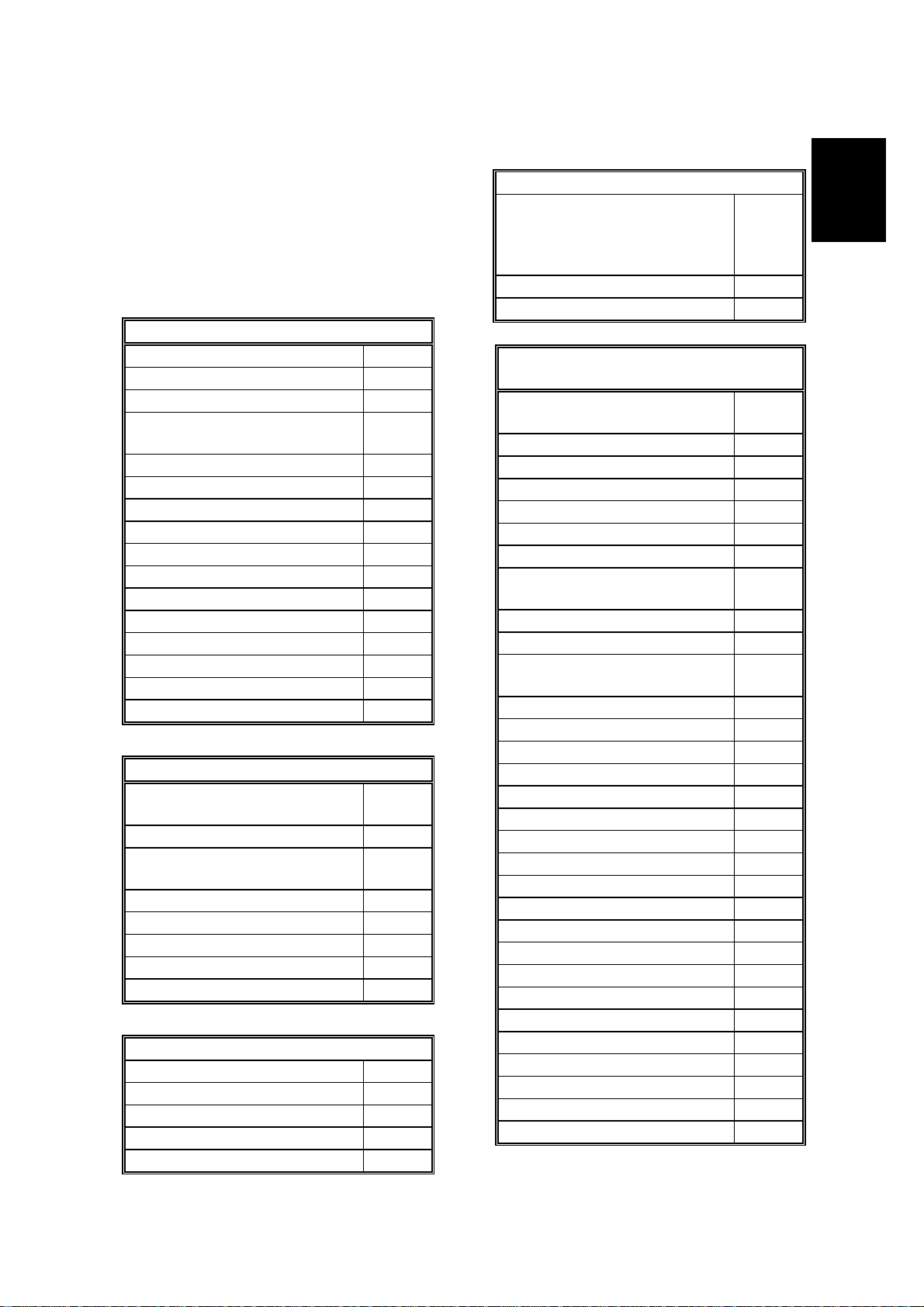
1.1 SPECIFICATIONS
Type
Desktop transceiver
Circuit
PSTN, PABX
Connection
Direct couple
Document Size
Length:
105 - 364 mm [4.1 - 14.3 ins]
Up to 1.2 m [47.2 ins], manually
assisted
Width:
148 - 217 mm [5.8 - 8.5 ins]
Thickness:
0.05 to 0.2 mm [2 to 8 mils]
(equivalent to 50 - 90 g/m
Document Feed
Automatic feed, face down
2
)
Compression
MH, MR, MMR, and SSC
SAF storage for memory TX: MMR
and/or raw data
Protocol
Group 3 with ECM
Modulation
V.34, V.33 (Ricoh mode only),
V.17 (TCM), V.29 (QAM), V.27ter
(PHM), V.21 (FM)
Data Rate (BPS)
33,600/31,200/28,800/26,400/24,000/
21,600/19,200/16,800/14,400/12,000/
9600/7200/4800/2400
I/O Rate
With ECM: 0 ms/line
Without ECM: 2.5, 5, 10, 20, or 40
ms/line
Overall
Information
ADF Capacity
30 sheets (using Letter size 20 lb paper
or A4 size 80 g/m2)
15 sheets (using LG size 20 lb. paper)
Scanning Method
Contact image sensor, with xenon lamp
Maximum Scan Width
216 mm [8.5 ins] ± 0.25%
(Effective scan width: 210 mm)
Scan Resolutions
Main scan:
8 dots/mm [203 dpi]
Sub scan:
Standard - 3.85 lines/mm [98 dpi]
Detail - 7.7 lines/mm [196 dpi]
Fine - 15.4 lines/mm [392 dpi]
Memory Capacity
ECM:
128 Kbytes
SAF:
Standard: 512 KB (40 pages/ITU-T #1)
With 1 MB option: 120 pages
With 2 MB option: 200 pages
Transmission Time
3 seconds at 28,800 bps: Measured
with G3 ECM using memory for an ITUT #1 test document (Slerexe letter ) at
standard resolution
Printing System
Laser printing, plain paper, dry toner
Printing Time
6 ppm for letter-size paper
Paper Size and Capacity
Standard Cassette:
250 sheets
Letter, Legal, A4, A5 sideways, F4
Multi-purpose Feeder (Optional):
100 sheets: Letter, Legal, Half-letter,
A4, A5, US-Exe, F4
10 sheets: OHP, Envelope
Paper Feed Unit (Optional):
500 sheets: Letter, Legal, A4,
A5 sideways, F4
1-1
Page 5

SPECIFICATIONS 6 November, 1998
Maximum Printing Width
208 mm [8.1 ins]
Print Resolutions
Fax and Copy Mode:
Main scan: 16 dots/mm [406 dpi]
Sub scan: 15.4 lines/mm [392 lpi]
Printer Mode:
600 x 600 dpi
Power Supply
115 ± 20 Vac, 60 ± 1 Hz
USA:
Europe/Asia:
220 - 240 ±15% Vac,
50/60 ± 3 Hz
Power Consumption (Base Machine
Only)
Standby:
Minimum 2 W; Normal 25 W
Transmit:
Receive:
Copying
42 W
280 W
: 370 W
Operating Environment
Temperature:
Humidity:
15 - 25 °C [59 - 77 °F]
30 - 70 %Rh
Dimensions (W x D x H)
399 x 730 x 323 mm
[15.7 x 28.7 x 12.7 ins]
Including trays (Maximum dimensions)
Weight
Approx. 12.5 kg [27.6 lbs.]
Including cartridge and trays.
1-2
Page 6
6 November, 1998 FEATURES
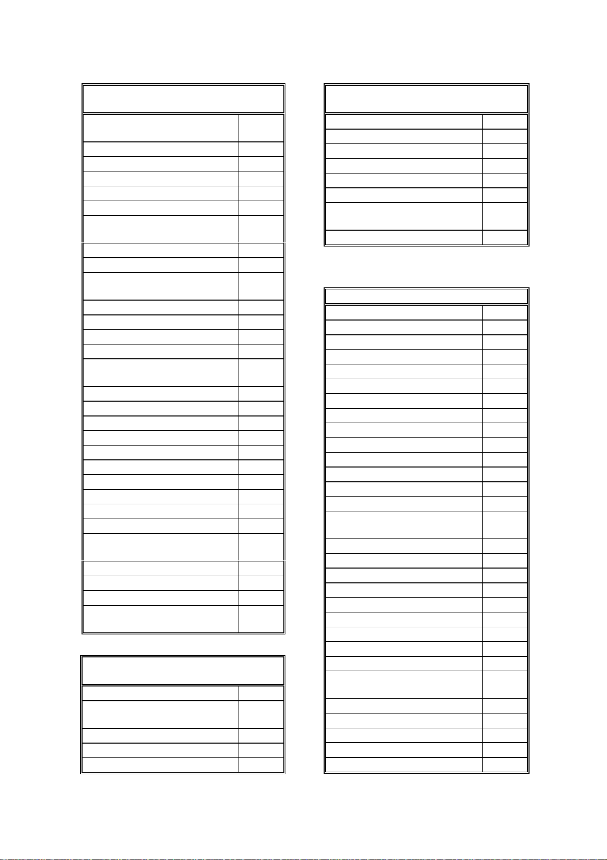
1.2 FEATURES
KEY: O = Used, X = Not Used,
A = With optional memory only,
B = With optional multi-purpose feeder only
C = With optional handset only
D = With optional PC interface only
E = With optional paper feed unit only
Equipment
ADF O
Book scan X
Bypass feed: 1 sheet X
Optional cassette: 100
sheets
Optional cassette: Universal O
Optional paper feed unit E
Cabinet X
Mechanical counter X
Cutter X
Handset C
Hard disk X
Manual feed mechanism X
Marker (Stamp) X
Monitor speaker O
Optional memory O
Optional printer interface D
Video Processing Features
Automatic image density
selection
Contrast O
Halftone (Basic & Error
diffusion)
JBIG compression X
MTF O
Reduction before TX X
Scanning resolution O
Smoothing to 16 x 15.4 l/mm O
Communication Features - Auto
AI short protocol O
Automatic fallb a ck O
Automatic redialing O
Confidential reception O
Dual access O
B
X
O
Communication Features - Auto
Resolutions available for
reception
Fine
Super fine
Substitute reception O
V.34 communication O
Communication Features -
User Selectable
Action as a transfer
broadcaster
AI Redial (last ten numbers) O
Answering machine interface O
Authorized Reception O
Auto dialing (pulse or DTMF) O
Auto document X
Automatic voice message X
Batch transmission (max 35
files)
Broadcasting O
Chain dialing O
Communication result
display
Confidential ID override X
Confidential transmission X
Direct fax number entry O
Economy transmission X
Fax on demand X
Forwarding O
Groups (5 groups) O
Hold X
ID transmission X
Immediate redialing O
Immediate transmission O
ISDN X
Keystroke programs O
Memory transmission O
Multi-step transfer X
OMR X
On hook dial O
Ordering toner X
Page count O
Page separation mark O
X
X
X
O
X
Overall
Information
1-3
Page 7
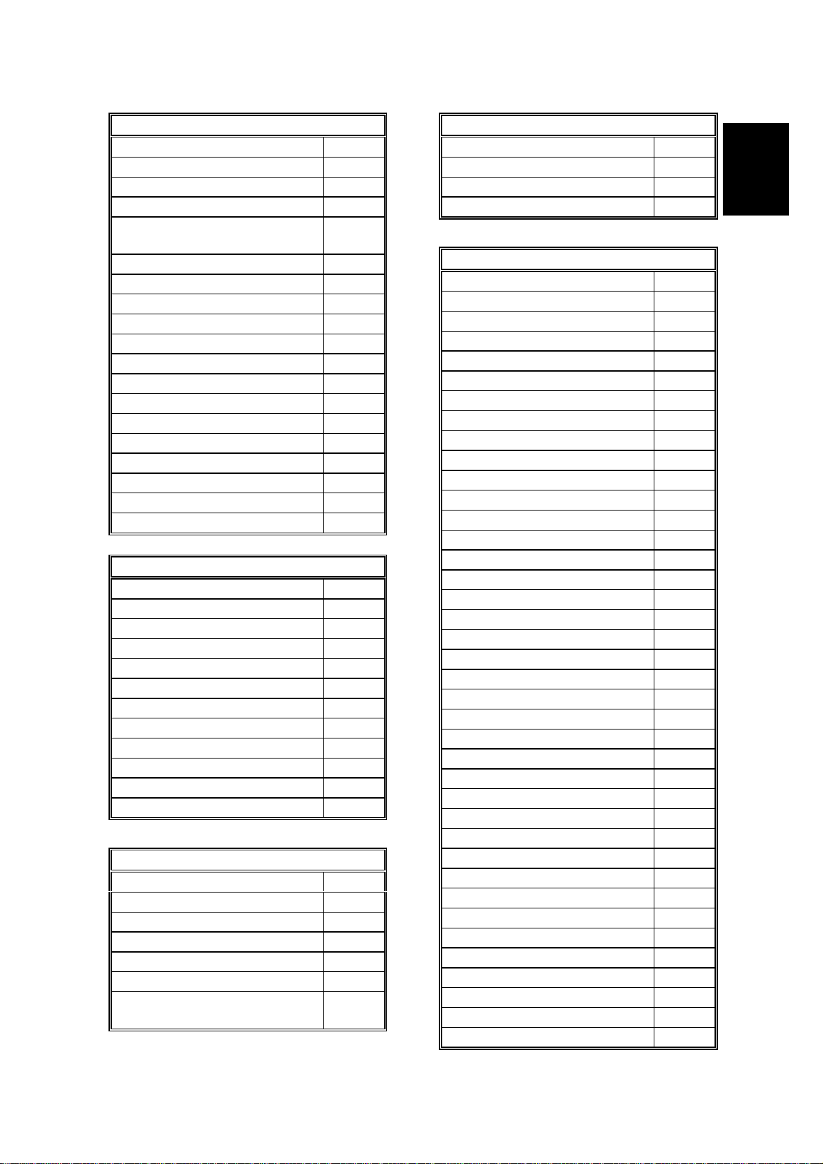
FEATURES 6 November, 1998
Communication Features -
User Selectable
Parallel memory
X
transmission
Personal codes O
Personal codes with conf. ID O
Partial image area scanning X
Polling reception O
Polling transmission X
Polling tx file lifetime in the
X
SAF
PWD (tx on l y) O
Quick dial (30 stations) O
Reception modes (Fax, Tel,
O
Auto)
Remote control features X
Remote transfer X
Restricted access X
Secured polling reception X
Secured polling reception
X
with Stored ID override
Send later O
SEP (tx only) O
SID (tx onl y) O
Silent ringing detection X
Specified Image area X
Speed dial (50 stations) O
SUB (tx only) O
Telephone directory O
Tonal signal transmission O
Transfer request X
Transmission deadline
X
(TRD)
Turnaround polling X
Two-step transfer X
Two in one X
Voice request (immediate TX
X
only)
Communication Features -
Service Selectable
AI short protocol O
Auto-reduction override
O
option
Busy tone detection O
Cable equalizer O
Closed network (TX and RX) X
Communication Features -
Service Selectable
Continuous polling reception X
Dedicated TX parameters O
ECM O
EFC X
Inch-mm conversion X
Page retransmission times O
Protection against bad
O
connections
Short preamble X
Other User Features
Area code prefix X
Automatic service call
Service
Center mark O
Checkered mark X
Clearing a memory file O
Clearing a polling file O
Clock O
Confidential ID O
Copy mode O
Copy mode restriction X
Counters O
Daylight saving time O
Destination check X
Direct entry of names O
Energy saver (Night timer
O
and standby mode)
File retention time X
File retransmission X
Function programs O
ID code X
Label insertion ("From xxx") O
Language selection O
LCD contrast control
Memory lock X
Modifying a memory file X
Multi-sort document
X
reception
Multi-copy mode (up to 99) O
Own telephone number O
PC scanner D
PC fax D
PC print D
X
1-4
Page 8
6 November, 1998 FEATURES
Other User Features
Print density control X
Printing a memory file O
Quick dial label printing O
RDS on/off O
Reception mode switching
X
timer
Reception time printing X
Remaining memory indicator O
Remote ID X
Reverse order printing O
RTI, TTI, CSI O
Service report transmission X
Speaker volume control O
Specified cassette selection E
Substitute reception on/off O
Telephone line type O
Toner saving mode X
User function keys O
User parameters O
Wild cards O
Reports - Automatic
Charge control report X
Communication failure report O
Communication result report O
Confidential file report O
Error report O
File clear report X
File reserve report X
Journal O
Power failure report O
Toner cassette order form X
Transfer resul t report X
Transmission result report O
Reports – User-initiated
Charge control report X
File list O
Group list O
Journal O
Personal code list O
Program list O
Programmed special
O
numbers list
Reports – User-initiated
Quick dial / User function list O
Speed dial list O
Transmission status report X
User parameter list O
Service Mode Features
Back-to-back test O
Bit switch programming O
Book mode test X
Buzzer test O
Cable equalizer O
Comm. Parameter display O
Counter check O
Country code O
DTMF tone test O
Echo countermeasure O
Effective term of service calls O
Error code display O
Excessive jam alarm O
File transfer (all files) O
LCD contrast adjustment X
Line error mark O
Memory file printout (all files) O
Modem software download X
Modem test O
NCU parameters O
Operation panel test O
Periodic service call O
PM call O
Printer mechanism test O
Printer test patterns O
Programmable attenuation X
Protocol dump list O
RAM display/rewrite O
RAM dump O
RAM test O
RDS O
Ringer test X
Scanner lamp test O
Scanner mechanism test O
Sensor initialization X
Serial number O
Service monitor report O
Service station number O
Software upload/download O
Overall
Information
1-5
Page 9

FEATURES 6 November, 1998
Service Mode Features
SRAM data upload/download O
System parameter list O
Technical data on the
Journal
Thermal head parameters X
O
Memory Files
Maximum number of files: 100
Maximum number of stations/file: 100
Maximum number of stations: 200
1-6
Page 10
4 September, 1998 COMPONENT LAYOUT
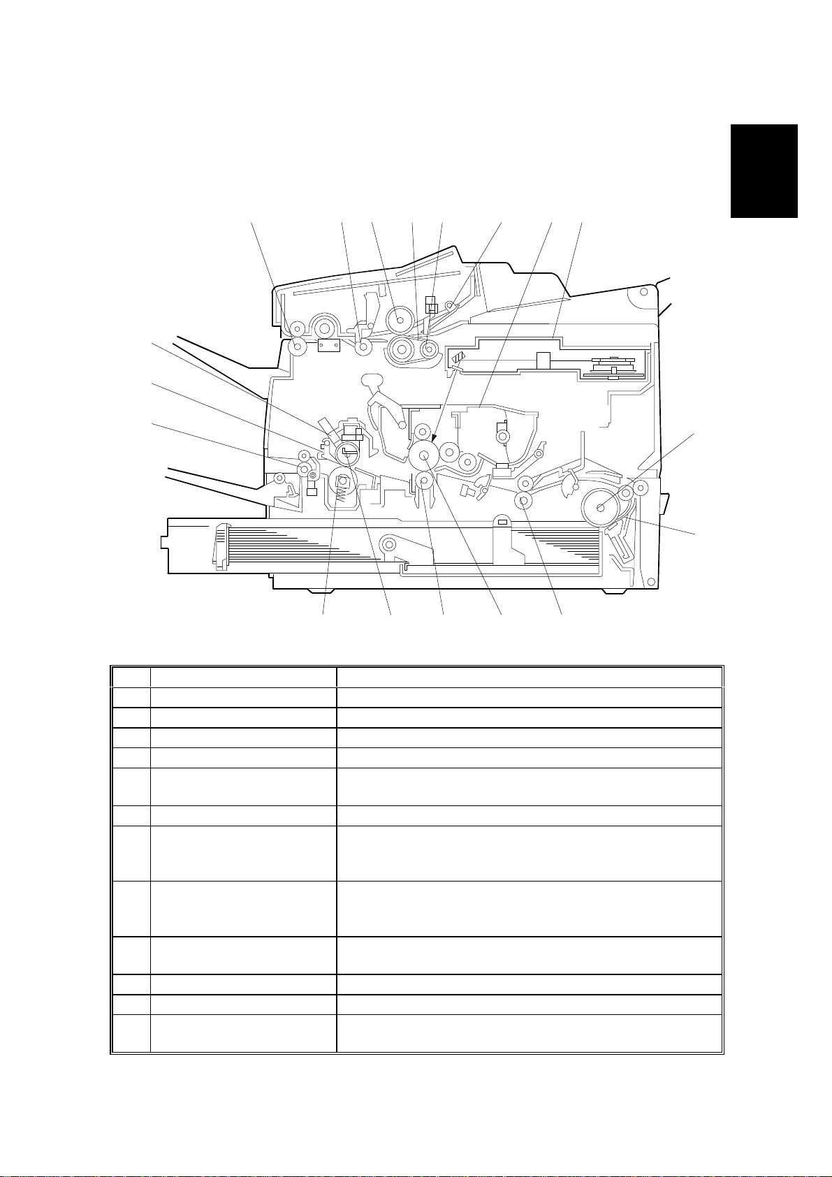
1.3 COMPONENT LAYOUT
1.3.1 MECHANICAL COMPONENTS
1 52 3 4 6 8
18
17
7
Overall
Information
16
H545V501.WMF
12
No Name Description
1 R2 Roller Feeds the document through the scanner.
2 R1 Roller Feeds the document through the scanner.
3 Separation Roller Allo ws one page into the scanner.
4 Document Feed Belt Feeds the document into the scanner.
5 Pick-up Roller
6 Pressure Plate Applies pressure against the pick-up roller.
7 All-in-One Cartridge Consists of the toner cartridge, cleaning unit, used
8 Laser Unit
9 Paper Feed Roller
10 Separation Pad Allows one sheet of paper into the printer.
11 Registration Roller Carr ies out the registration process.
12 OPC Drum The latent image is written to this organic
Picks up document pages from the document table
one at a time.
toner tank, charge brush roller, application roller,
development roller and OPC drum.
Consists of the LDDR (Laser Diode Driver), focusing
lens, hexagonal mirror motor, and other laser optic
components.
Picks up the top sheet of paper from the stack in the
cassette, and feeds it into the printer.
photoconductor drum.
11131415
9
10
1-7
Page 11

COMPONENT LAYOUT 4 September, 1998
No Name Description
13 Transfer Roller
14 Hot Roller Heat from this roller fuses the toner to the copy paper.
15 Fusing Pressure Roller Applies pressure to the paper during the fusing
16 Paper Feed-out Rollers Feed the paper out of the printer.
17 Hot Roller Strippers Take the paper off the hot roller after fusing.
18 Cleaning Pad Cleans up and spreads silicone oil on the surface of
Applies a charge to the paper to pull the toner off the
drum and onto the copy paper.
process.
the hot roller.
1-8
Page 12
4 September, 1998 COMPONENT LAYOUT
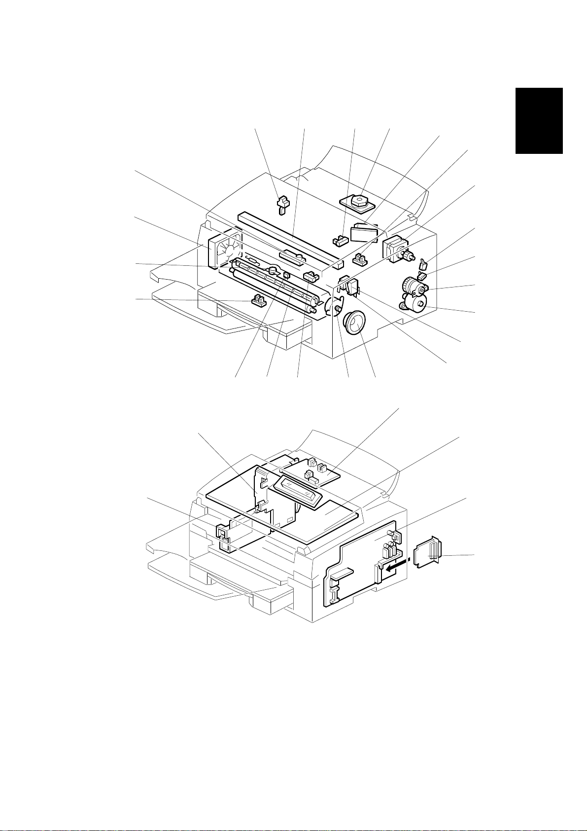
1.3.2 ELECTRICAL COMPONENTS
22
21
20
19
1 2 3 4
H545V502.WMF
141618
17
15
23
5
6
Overall
Information
7
8
9
10
11
12
13
27
28
24
25
26
H545V503.WMF
1-9
Page 13

COMPONENT LAYOUT 4 September, 1998
1. PCBs
No Name Description
CIS (Contact Image
2
Sensor)
5 LDDR (Laser Diode
Driver)
23 NCU (Network Control
Unit)
24 OPU (Operation Panel
Unit)
25 FCU (Facsimile Control
Unit)
26 PC Interface (Option)
27 Power Pack Supplies high voltage to the charge brush roller,
28 PSU (Power Supply
Unit)
This sensor reads and converts the light reflected from
the document into an analog video signal.
This board drives the laser diode.
This board contains relays and switches for interfacing
the machine with the network and the handset.
This board controls the operation panel.
This board controls the machine. It contains the main
CPU, flash ROM, system RAM, etc.
This allows the machine to be connected to a
computer as a PC printer, PC scanner, and PC fax.
transfer roller and development rollers.
This board supplies power to the machine, and
switches the fusing lamp on/off.
2. Motors
No Name Description
4 Polygon Mirror Motor This high-speed dc motor drives the hexagonal mirror
in the laser printer optics.
7 Main Motor This stepper motor drives the All-in-One cartridge and
the fusing unit.
11 Paper Feed Motor This stepper motor drives the registration roller and
the paper feed mechanisms in the cassettes.
15 Scanner Motor This stepper motor drives the scanner.
21 Cooling Fan Motor Cools the interior of the machine.
3. Sensors
No Name Description
1 Document Sensor Detects the presence of a document in the feeder.
3 Paper End Sensor Detects when the paper in the cassette has run out.
6 Paper Edge Sensor Detects when the paper has passed the paper feed
components.
8 Rear Upper Cover Switch
9 Rear Lower Cover Switch Detects whether the rear lower cover is open or
16 Registration Sensor Detects when paper reaches the registration roller.
19 Fusing Exit Sensor Detects when the paper feeds out of the printer.
22 Toner End Sensor Det ects when the toner has run out.
Detects whether the rear upper cover is open or
closed.
closed.
1-10
Page 14
4 September, 1998 COMPONENT LAYOUT
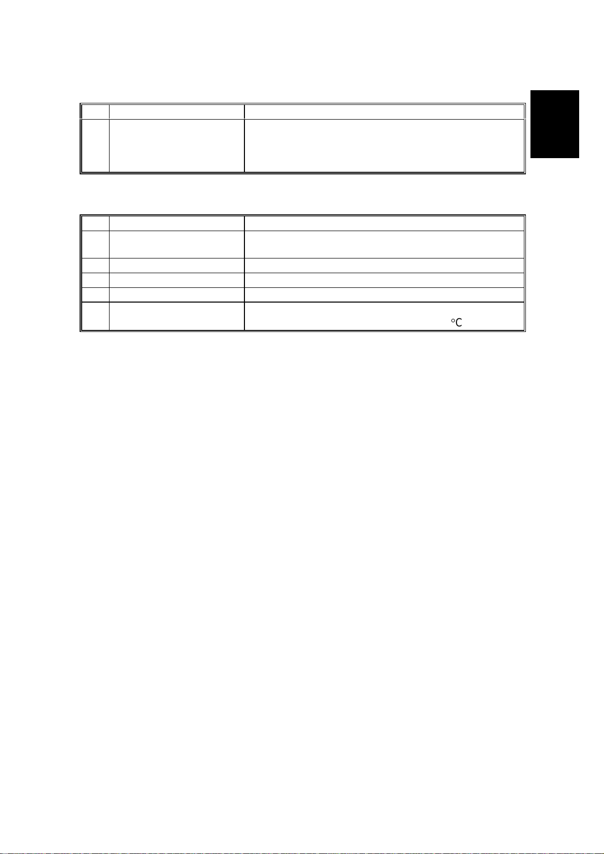
4. Interlock Switches
No Name Description
1213 Interlock Switches
If the fusing unit cover and/or top cover are open,
these switches interrupt the +5VLD power supply for
the laser diode and the +24VD power supply for the
power pack, motors, and other components.
5. Others
No Name Description
10 Paper Feed Clutch Transfers drive from the paper feed motor to the paper
feed roller.
14 Monitor Speaker Allows the user to hear the telephone line condition.
17 Fusing Lamp The heat from this lamp fuses the toner to the paper.
18 Thermistor Monitors the temperature on the hot roller surface.
20 Thermostat Interrupts the ac power supply for the fusing lamp if
the thermostat temperature exceeds 400°C.
Overall
Information
1-11
Page 15

COMPONENT LAYOUT 4 September, 1998
6. Optional Paper Feed Unit and Multi Purpose Feeder
1
2
5
3
8
H545V504.WMF
4
No Name Description
Paper End Sensor
1
(Paper Feed Unit)
2 Paper Feed Roller
(Paper Feed Unit)
3 Paper Feed Clutch
(Paper Feed Unit)
Cassette Switch
4
(Paper Feed Unit)
5 Rear Cover Switch
(Paper Feed Unit)
Paper Feed Roller
6
(Multi-purpose Feeder)
7 Paper Feed Solenoid
(Multi-purpose Feeder)
8 Paper End Sensor and
Paper Width Sensor
(Multi-purpose Feeder)
This detects when the paper in the cassette has run
out.
Picks up the top sheet of paper from the stack in the
cassette, and feeds it into the printer.
Transfers drive from the paper feed motor in the
mainframe to the paper feed roller in the cassette.
This detects whether the cassette is installed or not.
This detects whether the rear cover is open or close.
Picks up the top sheet of paper from the stack in the
feeder, and feeds it into the printer.
Transfers drive from the paper feed motor in the
mainframe to the paper feed roller in the feeder.
Paper end sensor: This detects when the paper in the
feeder has run out.
Paper width sensor: This detects the paper width
installed in the feeder.
7
6
H545V516.WMF
1-12
Page 16
4 September, 1998 OVERALL MACHINE CONTROL
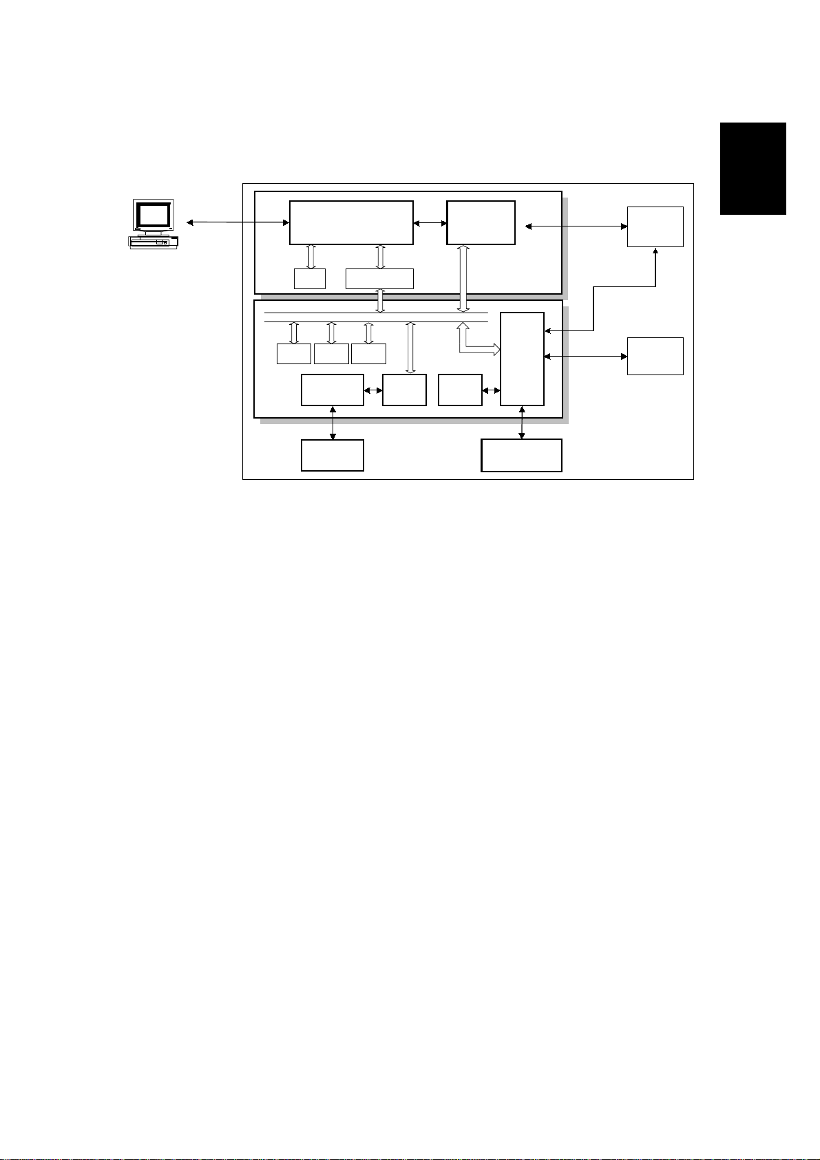
1.4 OVERALL MACHINE CONTROL
Bi-Centronics
(Parallel)
PC
FCU
DRAM
DRAM
SRAM
AFE
NCU
Address Data
Multiplexer
SYSTEM BUS
Flash
ROM
Modem
D9001LFD6002
Energy
Saver
CPU
FCIP2
Operation
Panel
PC I/F
Data
Data &
Control
Printer
Control
Scanner
H545V505.WMF
The FCU (Facsimile Control Unit) contains most of the logical components for
overall system control, and a direct interface to the IC card and PC interface board.
Overall
Information
There are two CPUs in the machine: the main CPU (FCIP2) and the energy saver
CPU. Both of these are on the FCU. In energy saver mode, the main CPU switches
off and the energy saver CPU takes over.
After installing the PC interface, the machine can communicate with a PC and work
multi-functionally as a PC printer, PC scanner and PC fax.
1-13
Page 17
VIDEO DATA PATH 4 September, 1998
y
g
y
y
y
1.5 VIDEO DATA PATH
1.5.1 TRANSMISSION
Original
Contact Image Sensor Assembl
LED
Image Sensor
Amplifier
Video
Processin
Memor
DATA/ADDRESS BUS
Line Buffer
/FIFO
Memor
DIP
FCIP2
DCR
DRAM
ECM/SAF
Memor
MDM Amplifier
Attenuator
HIC
NCU
To the network
H545V506.WMF
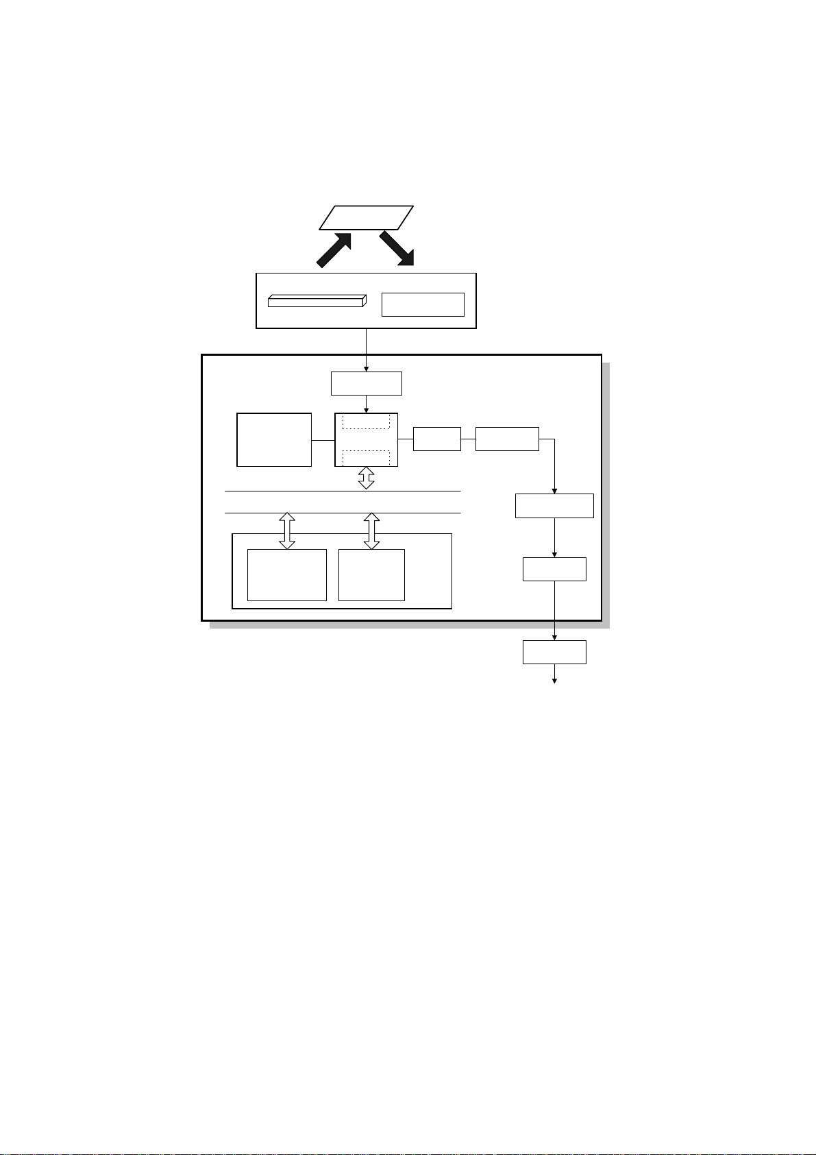
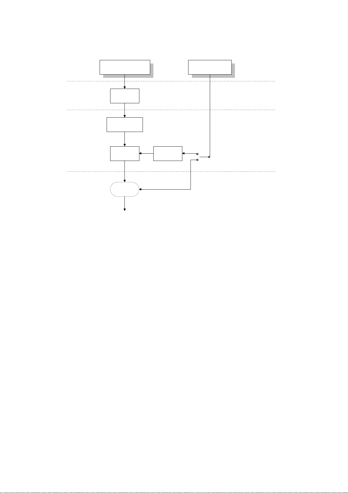
Immediate Transmission:
Scanned data from the contact image sensor passes to the DIP block in the FCIP2.
After analog/digital video processing, the DCR block compresses the data for
transmission. The compressed data then passes either to the FIFO memory or to
the ECM memory before entering the telephone line through the modem.
FCU
Memory Transmission:
First, the scanned data is stored in the SAF memory after compression in the DCR
block. At the time of transmission, the DCR block decompresses the data from the
SAF memory, then compresses it again after handshaking with the other terminal is
complete. The compressed data then passes either to the FIFO memory or to the
ECM memory, before entering the telephone line through the modem.
1-14
Page 18
4 September, 1998 VIDEO DATA PATH
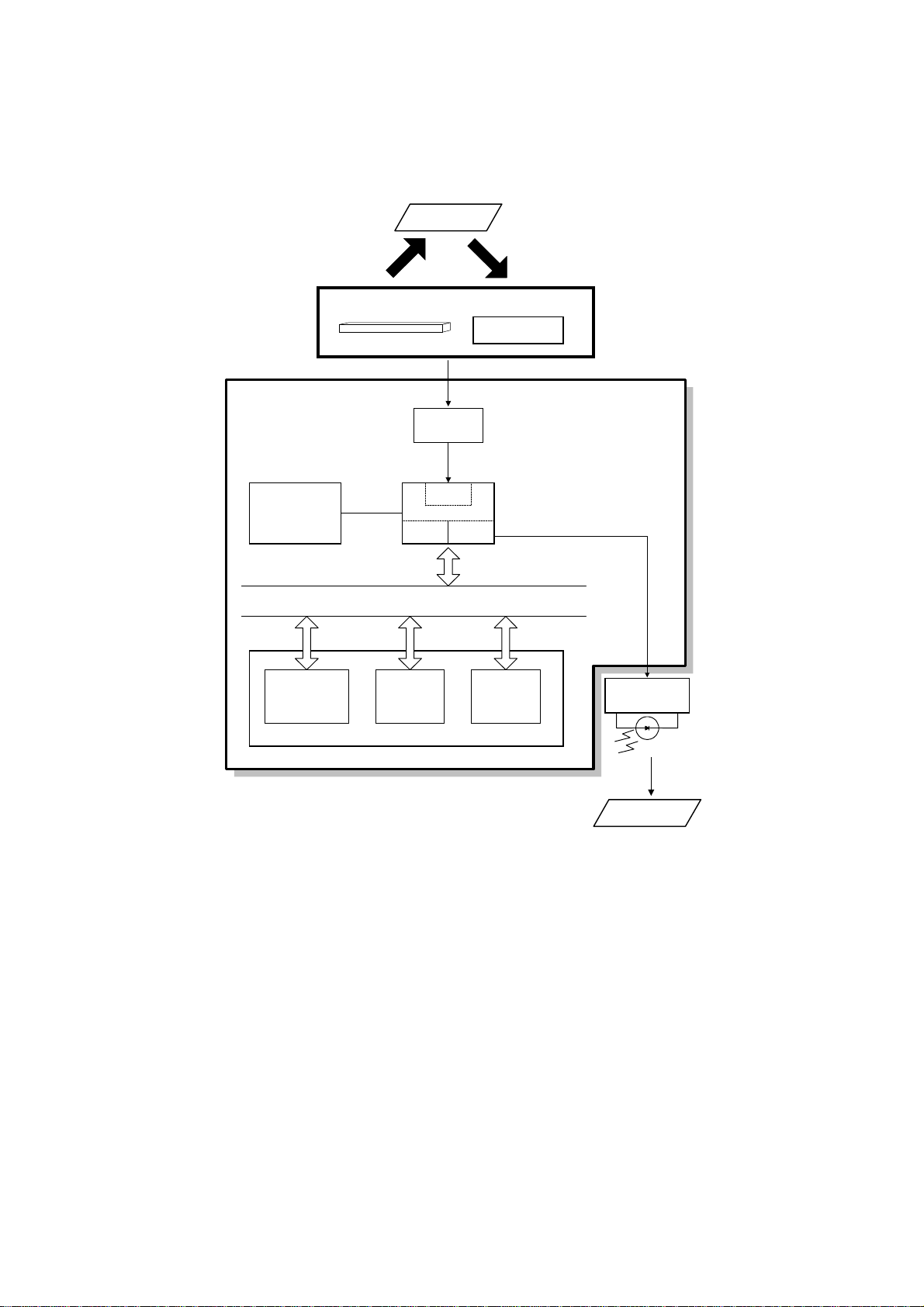
1.5.2 RECEPTION
From the Network
NCU
HIC
Amplifier
MDM
FCIP2
DCR LIF
MDM: Modem
DCR: Data Compression and Reduction
LIF: Laser Interface
FCU
Overall
Information
Data/ Address Bus
LDDR
Line Buffer
/FIFO
Memory
ECM/SAF
Memory
DRAM
Page
Memory
Copy Paper
H545V507.WMF
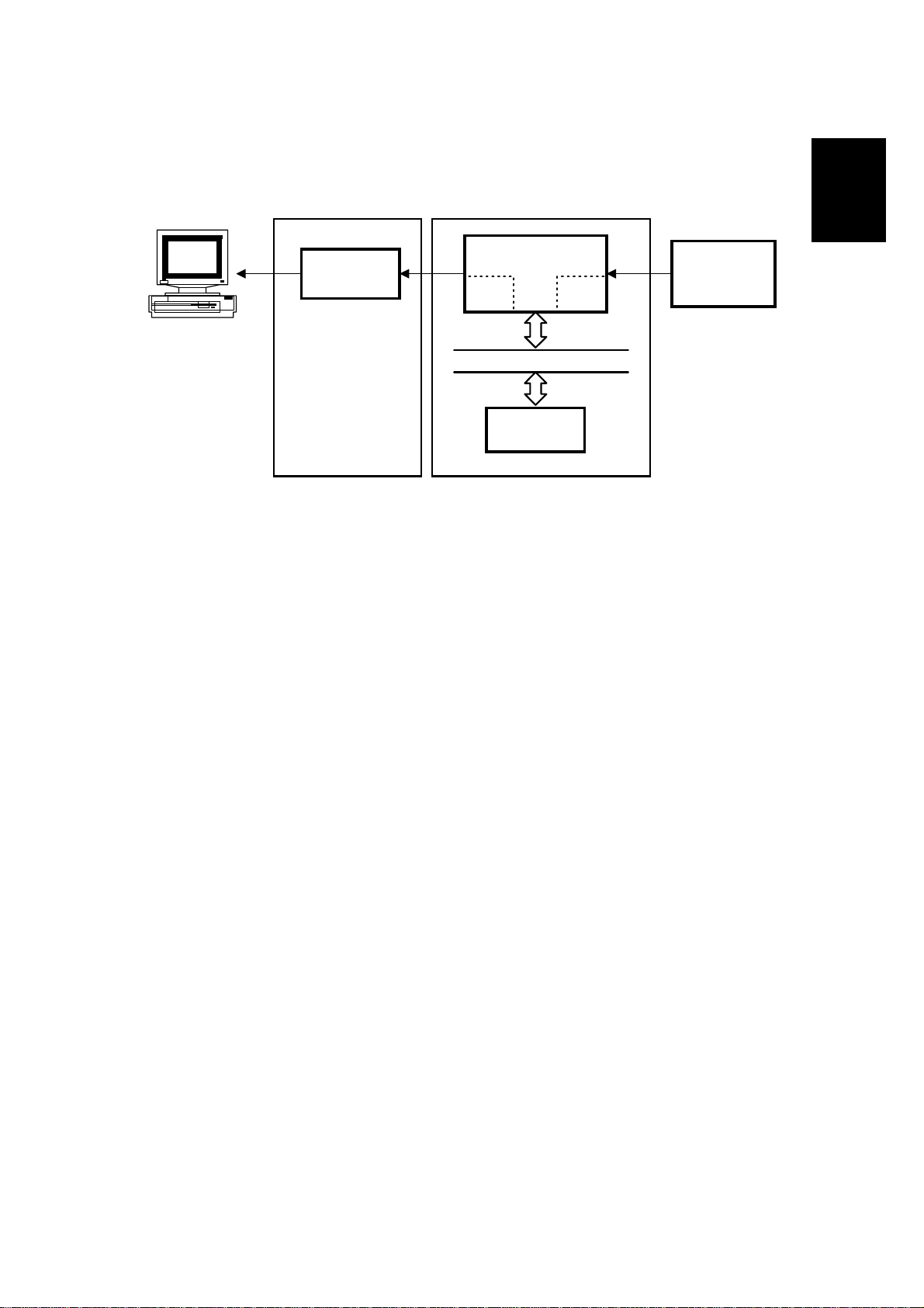
Data from the line passes to the modem through the NCU and hybrid integrated
circuit (HIC). After the modem demodulates the data, it passes through either the
FIFO or the ECM memory to the DCR block, which decompresses it into raster
image data. At the same time, the compressed data passes to the SAF memory as
a backup in case of mechanical problems during printing (this is known as
substitute reception).
The raster image data then passes to the page memory for printing. After a page of
data has been stored in the page memory, the data is sent to the LDDR through
the LIF block.
1-15
Page 19
VIDEO DATA PATH 4 September, 1998
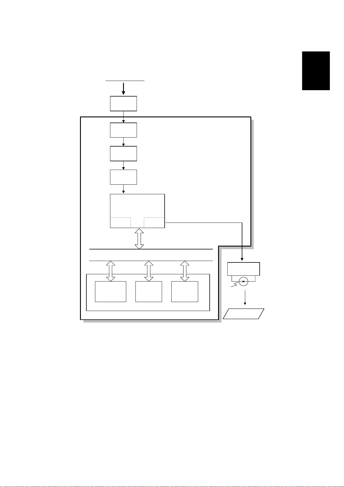
1.5.3 COPYING
Original
Contact Image Sensor Assembly
Video
Processing
Memory
Line Buffer
/FIFO
Memory
LED
Amplifier
FCIP2
DCR LIF
DATA/ADDRESS BUS
ECM/SAF
Memory
DRAM
Image Sensor
DIP
Memory
Page
FCU
LDDR
Copy Paper
H545V508.WMF
Single copy
The scanned data passes to the page memory after video processing in the DIP
block. After a page of data has been stored in the page memory, the data is sent to
the LDDR through the LIF block.
Multi-page copy
The scanned data passes to the SAF memory after video processing (DIP) and
compression (DCR). After a page of data has been stored in the SAF memory, the
data passes to the DCR block again for decompression, and then it passes to the
page memory for printing.
1-16
Page 20
4 September, 1998 VIDEO DATA PATH
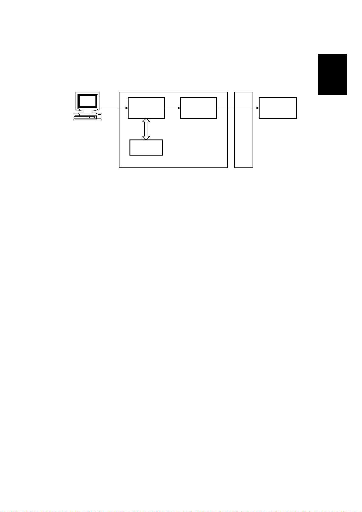
1.5.4 PC PRINTING
Overall
Information
PC
Data Data
D6002
DRAM
PC I/F
D9001
SJ4+
Data
FCU
Printer
Components
H545V511.WMF
This machine works as a GDI (Graphical Device Interface) printer when connected
to a PC through the parallel port.
When printing from the PC, the printer drive r (WinStyler T180) compresses the
video data and sends it to the D6002 IC through the parallel interface. The D6002
IC reconstructs the data and sends it to the D9001SJ4+ IC, which smooths the
data and treats it with the toner saving algorithm, if selected. The data is then sent
to the LDDR for printing.
Since the DRAM works as an I/O buffer, the page memory is not necessary for PC
printing.
1-17
Page 21
VIDEO DATA PATH 4 September, 1998
Windows
Application
GDI.exe
GDI printer
driver
Spooler
LPT port
Schmidt1
DOS
application
Application program
Windows program
PCL
interpreter
WinStyler program
H545V521.WMF
GDI Driver for Windows 95/98
A GDI printer has built-in support for the Windows Graphical Device Interface
(GDI). GDI is a Windows standard for displaying graphical objects on monitors and
printing these objects. Since most Windows applications use a GDI, it is not
necessary to convert the output to another format such as PostScript or PCL.
PCL Interpreter for DOS Printing
The PCL interpreter allows printing from a DOS window for DOS applications.
The PCL interpreter does not work in a pure DOS environment, and is not
supported under Windows NT4.0.
WinStyler T180 does not have a PCL driver mode for printing from Windows
applications.
1-18
Page 22
4 September, 1998 VIDEO DATA PATH
1.5.5 PC SCANNING
PC
D6002
FCIP2
Scanner
DCR DIP
Data/Address Bus
ECM
Memory
Overall
Information
PC I/F
FCU
H545V512.WMF
The scanned data passes through the DIP block in the FCIP2 for analog/digital
processing. The DCR block in the FCIP2 compresses the data and passes it
through the ECM memory. Then it goes to the PC through the D6002 without any
processing. The data is reconstructed in the driver in the PC (the image processing
is the same as for fax scanning).
1-19
Page 23
VIDEO DATA PATH 4 September, 1998
y
1.5.6 PC FAX
PC
PC I/F
Data/Address Bus
FCU
D6002
FCIP2 Modem
Amplifier
ECM
Memor
HIC
NCU
To the network
H545V514.WMF
PC Fax Transmission
The application software compresses the PC data. It then produces the AT
commands and sends them to the specified PC parallel port.
Then the commands and data are sent from the parallel port to the machine. The
D6002 passes these to the FCIP2. The FCIP2 controls the modem in accordance
with the AT commands sent from the PC. It then sends the data to the ECM
memory through the D6002 (the D6002 does not process the data), and on to the
telephone line through the modem and the NCU.
PC Fax Reception
The data from the line passes to the modem through the NCU. The data
demodulated in the modem passes to the D6002 through the ECM memory. The
PC Fax application software then reconstructs the data.
1-20
Page 24
4 September, 1998 POWER DISTRIBUTION
1.6 POWER DISTRIBUTION
1.6.1 DISTRIBUTION DIAGRAM
AC
Main
Power
AC Switching
Fusing Lamp
ON/OFF
Switching
AC115V or
Fusing Lamp
Circuit
Circuit
230V
PC I/F
Main Switch
PSU
24VIN
+5V
+5VE
IC
Card
-9V
+24V
+5VD
24VM
24VD
+5V
Paper Feed
+5VP
Converter
Converter
Interlock
Unit
+5V
DC-DC
DC-DC
Switch
+24VM
Multi Purpose
Feeder
+12V
+5VE
+5VLD+5V
Polygon
Motor
+5V
+5V
+24VM
-9V
Converter
+5VLD
+24V
+5V
+5VEE
LDDR Image Sensor
NCU
DC-DC
+5V
Main
Motor
+24VMM
+24VM
-9VV
Paper Feed
Clutch
FCU
+5VV
+24VMS
+24VMM
+24VM
+24VPP
+5VT
+5V
+5VOPP
+5VE
+24VMM
+24V
Paper Feed
Motor
Fusing Fan
Power Pack
Thermistor
Sensors
Operation Panel
Scanner Motor
Toner End
Sensor
+5V
-9V
Overall
Information
H545V515.WMF
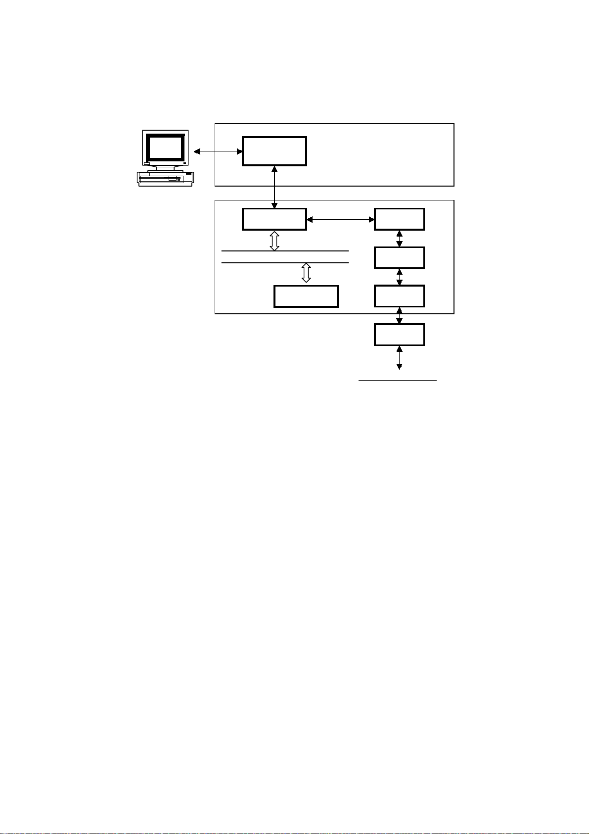
The PSU supplies +24V dc power to the FCU. The FCU converts the +24V into the
following supplies:
+5V Normally on when the main switch is.
+5VE Detects an activation signal from the NCU, document feeder, or operation panel
when the machine is in energy saving mode.
+5VT For the thermistor.
+5VLD Supplies the laser diode. It is interrupted if the fusing unit cover interlock switch
opens.
+5VV This is a more stable power supply than +5V. It is used for the contact image
sensor.
+5VD
+5VBAT
+24V Normally on when the main switch is.
+24VD This is interrupted if the fusing unit cover interlock switch opens.
+24VIN
+24VMM For the scanner, paper feed, and main motors.
+24VPP For the power pack.
-9V For the image sensor.
+5VP For the optional IC card.
Supplies back up power for the DRAM and the optional IC card on the FCU. It can
back up stored data for one hour after the power is switched off. A rechargeable
battery on the FCU generates +5VD.
Supplies back up power to the system RAM on the FCU to back up the
programmed data. A lithium battery generates +5VBAT.
Supplies +24V to the fusing unit on/off switching circuit. It is interrupted if the fusing
unit cover interlock switch opens.
1-21
Page 25
6 November, 1998 SCANNER
2. DETAILED SECTION DESCRIPTIONS
2.1 SCANNER
2.1.1 MECHANISMS
1. Document Detection
[A]
H545D512.WMF
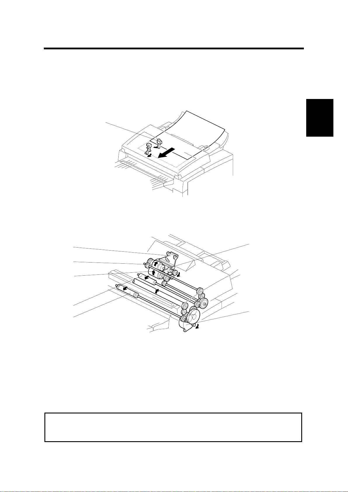
The document sensor [A] detects a document when it is placed in the ADF.
2. Pick-up and Separation and Drive Mechanism
[A]
[B]
[D]
[C]
Detailed
Descriptions
[F]
[E]
[G]
H545D502.WMF
The pressure plate [A] aligns the leading edges of the pages of the document.
When the machine starts feeding the document, the mechanical clutch in the ADF
roller unit lifts up the pick-up rollers [B] to feed the bottom sheet of the document.
Then, the feed belt [C] feeds the sheet into the scanner.
The separation roller [D] prevents the feed belt from feeding more than one sheet
at a time.
The scanner motor [E] drives the pick-up rollers [B], feed belt [C], R1 roller [F], and
R2 roller [G].
Cross Reference
ADF mechanical clutch mechanism: Group 3 Facsimile Manual, page 2-2-8.
Maximum document length: Scanner Switch 00, bits 2 and 3.
2-1
Page 26

SCANNER 6 November, 1998
4. Image Scanning
[A]
[B]
[C]
H545D503.WMF
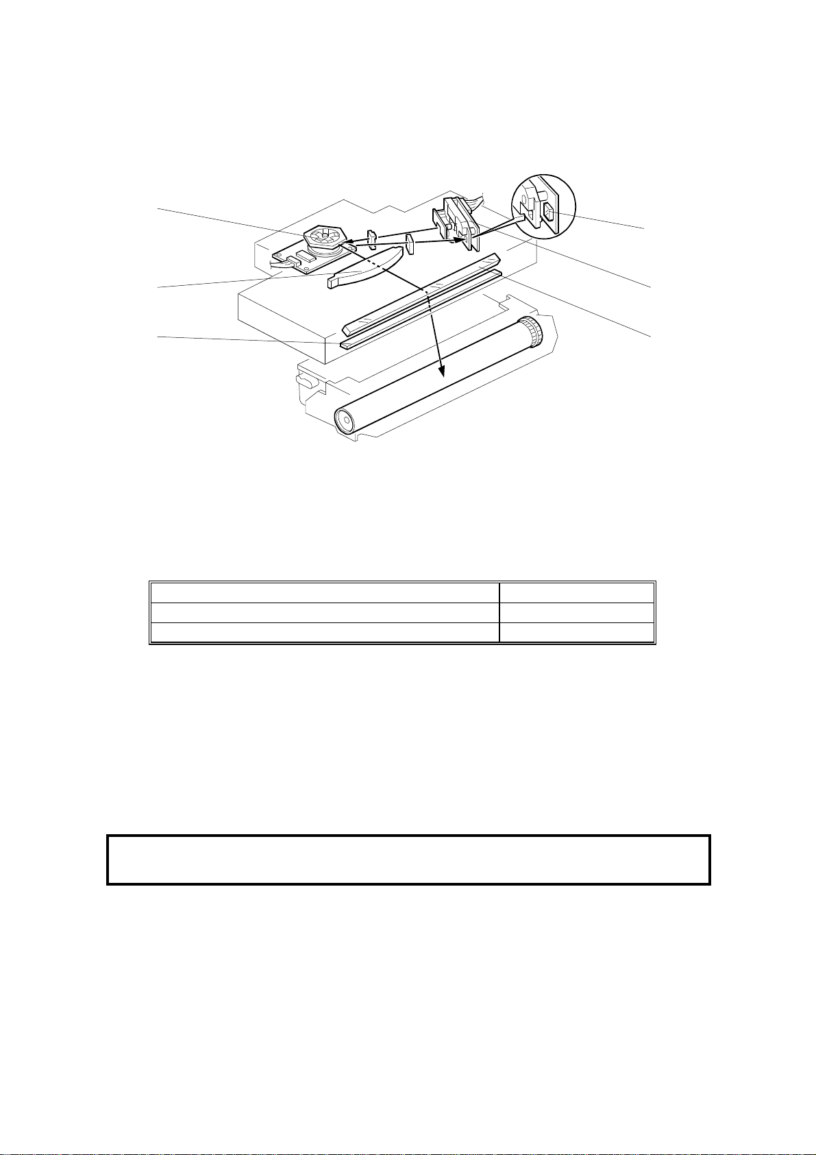
The image sensor [B] consists of a row of 1728 photosensitive elements (Letter
width x 8 dots/mm). The document reflects light from the LED array and the rod
lens array focuses it onto the image sensor. Because of the short optical path
inside the CIS, the focal depth is much shorter than for a CCD type scanner.
Consequently, the spring plates [C] push the white roller [A] so that the document
surface always touches the exposure glass at the scan line.
The image sensor assembly is factory adjusted, so it does not require adjustment
or replacement in the f ield.
The image sensor scans the original one line at a time, and outputs an analog
signal for each line. The voltage from each element depends on the intensity of the
light reflected from the original onto the element; the light intensity depends on the
darkness of the document area it was reflected from.
The white roller [A] must be kept clean, because the machine scans it every page
to calibrate the white level (auto shading).
2-2
Page 27

6 November, 1998 SCANNER
2.1.2 JAM CONDITIONS
The main CPU detects a document jam if one of the following conditions occurs.
Jam Condition Description
Non-feed The feed mechanism attempts to feed the
paper once every second for a maximum of
6 seconds. If the scan line sensor does not
detect the document within 6 seconds, the
monitor displays an error message.
Incorrect sensor
conditions
Maximum document length
exceeded
Cover open While the ADF is working, the ADF cover is
Error during feed-out
The scan line sensor turns on while the
document sensor is off.
The scan line sensor does not turn off after
the maximum document length has fed
through it. This occurs after 11 seconds at
standard resolution for memory TX; 23
seconds at standard resolution for
immediate TX or detail resolution; or 46
seconds at fine resolution (all these times
are for a 1.2-m long document).
opened.
The scanner motor reverses when the final
page of the document feeds out of the
scanner and/or when removing a jammed
document. This error occurs when placing a
document into the feeder while the motor is
rotating.
Error
Code
1-00
Detailed
Descriptions
1-01
No error
code
No error
code
2-3
Page 28
PRINTING 6 November, 1998
2.2 PRINTING
2.2.1 PRINTING PROCESS - OVERVIEW
-1.2kV
-200V
m
+4.3
A
m
-650V
(0V)
H545D521.WMF
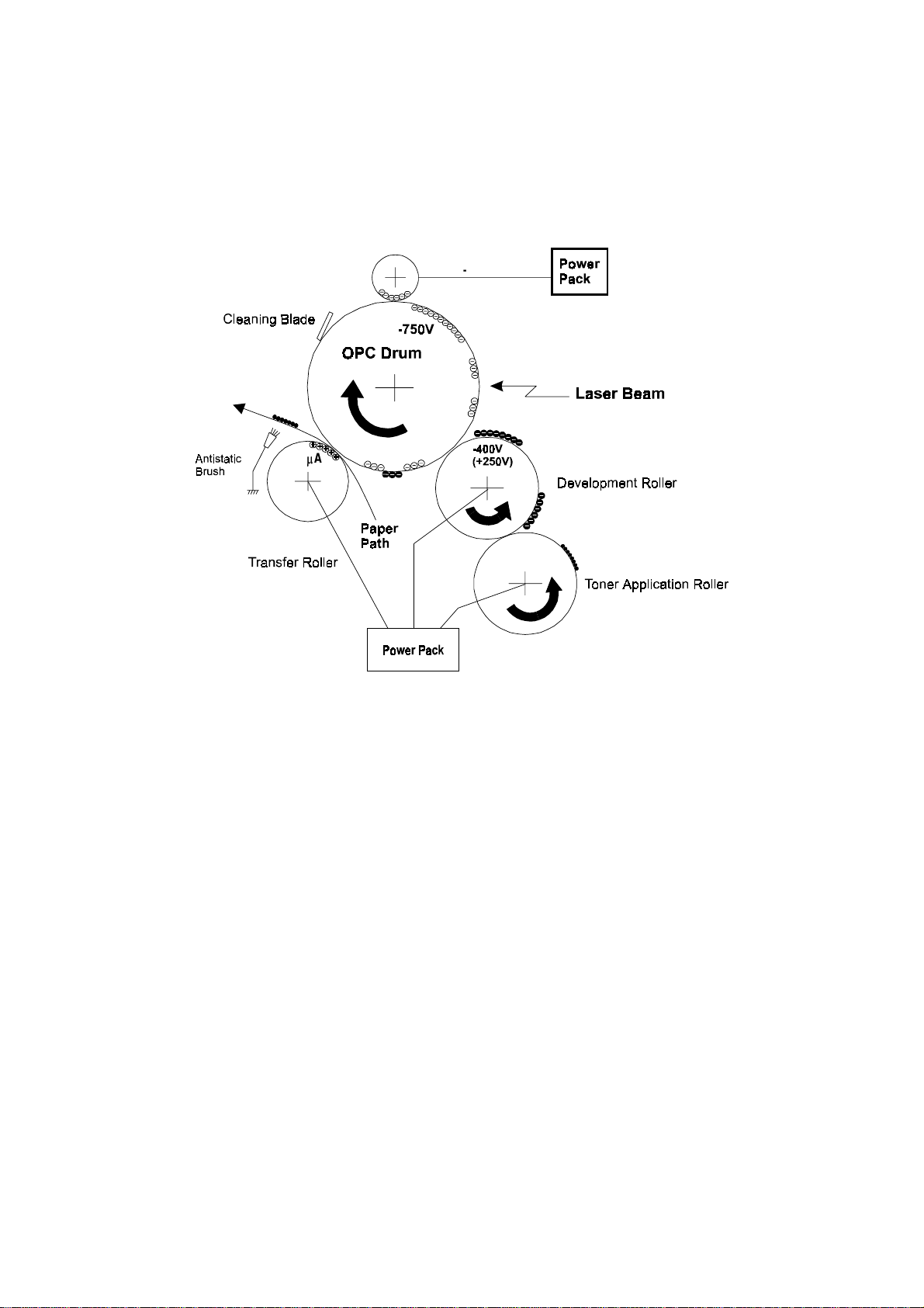
This machine uses a “write-to-black” system, with negative toner.
·
The charge-brush roller gives the drum surface an approximate negative
charge of -750 V.
·
The exposed area on the drum drops to about -200 V.
·
The development roller carries toner to the latent image on the drum surface.
The bias voltages during printing:
Toner application roller : -650 V
Development roller: -400 V
·
The transfer roller pulls the toner from the drum onto the paper.
A constant current of +4.3 mA is applied. The anti-static brush helps to
separate the paper from the drum.
·
The cleaning blade removes any toner remaining on the drum after the image
transfers to the paper.
·
This machine does not use quenching lamp.
2-4
Page 29
6 November, 1998 PRINTING
2.2.2 OPC DRUM
[C]
[D]
[B]
[A]
[E]
H545D504.WMF
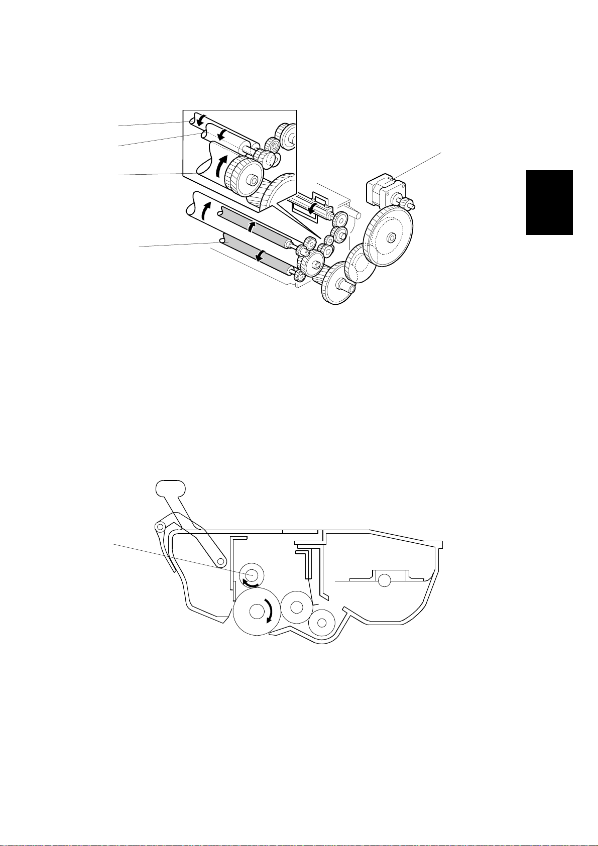
The cartridge contains an organic photo-conductor drum [A]. The diameter of the
drum is 24 mm. The main motor [B] drives it through a gear train. The same gear
train also drives the toner application roller [C], development roller [D], and transfer
roller [E].
The drum, development roller, fresh and used toner tanks, and cleaning
mechanism are all included in the cartridge, which is known as the “All-in-One”
cartridge.
Detailed
Descriptions
2.2.3 CHARGE
[A]
H545D517.WMF
The cartridge contains a charge brush roller [A]. The diameter of the roller is 12
mm. The charge brush roller does not generate ozone. The power pack applies a
constant voltage of about –1.2 kV. The charge brush roller gives the drum surface
a negative charge (-750V).
2-5
Page 30
PRINTING 6 November, 1998
2.2.4 LASER EXPOSURE
Overview
[C]
[E]
[A]
[B]
H545D505.WMF
·
The focusing lens [A] is a double toroidal lens that has a barrel toroidal
[D]
[F]
surface on both sides.
·
The shield glass [B] prevents toner and dust from entering the laser optics
area.
·
The speed of the hexagonal mirror motor [C] depends on the printing
resolution:
Mode Speed
Copy and Fax - mm mode (16 x 15.4 dots/mm) 5793.88 rpm
Printer mode (600 dpi) 8886.59 rpm
·
The strength of the beam emitted from the LD unit [D] is 0.2 mW with a
wavelength of 780 nm . The photo transistor [E] inside the LD unit
synchronizes the laser main scan.
·
The mirror [F] reflects the laser beam onto the drum.
The charge on the exposed areas of the drum drops to about -200V while nonexposed areas remain at around -750V.
As a mechanical safety feature, a shutter slides to block the laser beam path
whenever the upper unit is opened.
Cross Reference
Group 3 Facsimile Manual: section 4-3-3
2-6
Page 31

6 November, 1998 PRINTING
Block Diagram
LDDR
Laser
Synch
Detector
Circuit
Laser
Diode
Controller
Laser
Diode
Polygon
Mirror
Drive Unit
Laser Synch
Detector
26-4
LD Enable
DATA
Control
Mirror Motor Lock
Mirror Motor Enable
9-2
9-6
9-3
10-4
10-3
FCU
FCIP2
LIF
EXIO
H545D506.WMF
The LIF (Laser Interface) circuit inside the FCIP2 monitors and controls the laser
diode timing (FCU CN9-3), and transfers data for printing to the laser diode (FCU
CN9-6).
Detailed
Descriptions
Cross Reference
Group 3 Facsimile Manual: page 4-3-13
Error Conditions
LD Failure:
The machine detects LD failure when it does not detect the laser synchronization
signal within 10 ms of the LD ready signal. When this occurs, the machine warns
the customer with the Call Service indicator (error code 9-20).
Mirror Motor Failure:
The machine detects a mirror motor error when the FCU CN10-4 signal does not
go low within 10 seconds of the hexagonal mirror motor turning on.
The machine also detects a mirror motor error when the FCU CN10-4 signal goes
back to high for 3 seconds or more during mirror motor operation. When either of
these errors occurs, the machine warns the customer with the Call Service
indicator (error code 9-23).
2-7
Page 32

PRINTING 6 November, 1998
2.2.5 TONER SUPPLY
[C]
[A]
[B]
H545D519.WMF
This machine uses mono-component toner, composed of resin and ferrite. The
toner mixing bar [A] stirs and carries toner to the toner application roller [B]. The
toner application roller supplies toner to the development roller [C].
The main motor drives the toner supply mechanism through a gear train.
Since the toner tank and the development unit is composed in one unit, initial toner
supply mode is not required for this machine.
Cartridge Detection
This machine does not have toner cassette detection mechanism. It only detects
output from the toner end sensor.
At the following times, the toner end sensor detects whether a cartridge is installed
in the machine.
·
At power-up.
·
When the machine comes back to normal mode from the level 2 Energy
Saver Mode.
·
After opening and then closing the cover.
2-8
Page 33

6 November, 1998 PRINTING
Toner End Detection
[A]
H545D516.WMF
The toner end sensor [A] below the toner tank detects toner near-end.
While the main motor rotates, the machine detects toner end by the voltage output
from the toner end sensor. The voltage from the sensor is close to 5V when the
toner tank is full and decreases when the toner is almost used up.
Detailed
Descriptions
FCU
Toner Tank
+24V
Toner End
Sensor
Toner near-end condition:
13-1
13-2
When the cpu detects a low output (below a certain
+5V
FCIP2
H545D507.WMF
threshold) from the toner end sensor for a few seconds, the cpu starts to blink the
Add Toner indicator (LED). This is the toner near-end condition.
Toner end condition:
After toner near-end is detected, the machine can print 100
more sheets, then the cpu disables printing (this is the toner end condition).
The machine clears the toner near-end or toner end condition when the power is
switched off and back on or when the cover is opened and closed, if the output
from the toner end sensor goes back high again.
NOTE:
If the toner end sensor is accidentally disconnected, the machine cannot
detect if the cartridge is installed. The machine assumes that there is still
toner, even if the toner tank is empty.
2-9
Page 34

PRINTING 6 November, 1998
2.2.6 DEVELOPMENT
[C][D]
[A]
[B]
[E]
H545D519.WMF
Overview
The toner supply bar [A] stirs and carries toner to the toner application roller [B].
The toner application roller is a sponge-like structure which carries toner to the
development roller [D]. As the development roller [D] turns past the toner metering
blade [C], only a thin coating of negatively charged toner particles stays adhered.
(Refer to section 4-4-2 of the Group 3 Facsimile manual.)
During printing, the power pack applies a bias voltage of -650V to the toner
application roller and another bias voltage of -400V to the development roller. The
potential difference between these two rollers carries the toner from the toner
application roller to the development roller.
The exposed area on the drum [E] is at -200V. The development roller applies
toner to the latent image areas as they turn past the drum.
The development roller is made of soft rubber so it does not damage the surface of
the drum.
2-10
Page 35

6 November, 1998 PRINTING
Development Bias
[C]
[B]
[D]
[A]
H545D518.WMF
The power pack [A] applies one voltage to the toner application roller [B] and toner
metering blade [C], and a different voltage to the development roller [D].
Bias Control (During Printing)
The power pack applies a charge of -650V to the toner application roller, and
-400V to the development roller. Toner transfers from the toner application roller to
the development roller and on to the laser-exposed areas on the drum as shown
below.
Print Data
White Black
Toner
Detailed
Descriptions
GND
- 200V
- 400V
- 650V
- 750V
Drum Exposed Area
Development Roller
Toner Application Roller
Drum Surface Voltage
H545D531.WMF
2-11
Page 36

PRINTING 6 November, 1998
Bias Control (After Each Page)
At the start and the end of any print process (including the cleaning mode), the
power pack applies 0V to the toner application roller, and +250V to the
development roller. This is to prevent toner from transferring to the drum.
Toner
+ 250V
0V
- 750 V
Development Roller
Toner Application Roller
Drum Surface Voltage
H545D533.WMF
Note that the voltage difference between the toner application and development
rollers is kept the same as in printing, at 250 V. This keeps the same amount of
toner on the development roller at all times during the print run.
2-12
Page 37

6 November, 1998 PRINTING
Bias Control Circuit
Toner Application
Roller
Development
Roller
Transfer Roller
Power
Pack
BIASPWM
BIASCTL
Transfer H
Transfer L
11-8
11-7
11-10
11-9
GEPC
FCIP2
FCU
H545D509.WMF
The CPU controls the voltages to the toner application and development rollers
through the power pack controller (GEPC), using the BIASCTL and BIASPWM
signals as shown in the following table.
In BIASCTL Low High Low High
BIASPWM On On Off Off
Out Toner Application Roller - 650 V 0 V Off Off
Development Roller - 400 V + 250 V Off Off
Detailed
Descriptions
2-13
Page 38

PRINTING 6 November, 1998
2.2.7 PAPER FEED
Overview
[B]
[A]
H545D511.WMF
The standard cassette [A] holds 250 sheets.
An optional paper feed unit, which holds up to 500 sheets, is available (only one of
these can be installed). An optional multi-purpose feeder [B] is also available.
2-14
Page 39

6 November, 1998 PRINTING
Paper Lift Mechanism
Standard Cassette
[A]
[C]
[B]
H545D525.WMF
After loading the paper and closing the cassette, the projection [A] pushes the slide
lock [B] off the bottom hook [C].
Once the slide lock comes off, the pressure spring lifts the bottom plate.
Optional Paper Feed Unit
[A]
[B]
Detailed
Descriptions
H545D513.WMF
After loading the paper and closing the cassette, the projection [A] pushes the lever
[B], then the springs raise the bottom plate.
2-15
Page 40

PRINTING 6 November, 1998
Paper End Detection
Standard Cassette/Optional Paper Feed Unit/Optional Multi-purpose Feeder
[A]
H545D527.WMF
When the cassette runs out of paper, the paper end sensor actuator [A] drops
through a slot in the bottom plate.
Paper End Sensor
Standard Cassette
Paper End Detector
Paper Feed Unit
Paper End Sensor
Multi Purpose Feeder
FCU
25-6
31-3
32-2
Paper End
EXIO
Paper End
Paper End
FCIP2
H545D659.WMF
2-16
Page 41

6 November, 1998 PRINTING
Pick-up and Separation
Standard Cassette and Optional Paper Feed Unit
The pick-up and separation mechanism is a separation pad type. The separation
pad and the paper feed roller allow only one sheet to feed.
Cross Reference
Group 3 Facsimile Manual: section 4-5-4
The paper feed motor in the mainframe starts to rotate when the printer is ready for
printing.
Drive Mechanism
Standard Cassette
[B]
[C]
[A]
Detailed
Descriptions
H545D522.WMF
The paper feed motor [A] drives the paper feed mech ani sm. When using the
standard cassette, the paper feed motor turns clockwise, driving the paper feed
roller [B], as shown in the diagram.
The clutch [C] only allows the paper feed roller to turn once for each sheet of
paper.
2-17
Page 42

PRINTING 6 November, 1998
Optional Paper Feed Unit
[A]
[B]
[C]
H545D508.WMF
The paper feed motor in the main fr am e drives the paper feed mechanism through
a gear train. When the optional paper feed unit is used, the paper feed motor turns
counter-clockwise, driving the paper feed roller [A] and the transport roller [B], as
shown.
The paper feed clutch [C] in the optional paper feed unit ensures that the paper
feed roller rotates only once for each sheet of paper.
Optional Multi-purpose Feeder
[A]
[B]
H545D515.WMF
[C]
The paper feed mechanism is driven from the paper feed motor in the mainframe
through a gear train. When the machine feeds a sheet of paper from the multipurpose unit, the paper feed motor in the mainframe turns counter-clockwise to
drive the paper feed roller [A] and the transport roller [B] as shown in the diagram.
The paper feed solenoid operates the clutch [C] in the optional multi-purpose unit
to ensure that the paper feed roller rotates only once for each sheet of paper.
2-18
Page 43

6 November, 1998 PRINTING
Paper Feed Priority
If there is an optional paper feed unit and/or multi-purpose feeder installed in the
machine, deciding paper feed priority is in accordance with the following rules:
·
If the machine has an optional multi-purpose feeder and all of the cassettes
contain paper of the same size, the machine uses the optional paper feed
unit first, the standard cassette second, and the multi-purpose feeder third.
·
The multi-purpose feeder can be set to print only from a PC by a user
parameter switch adjustment.
2.2.8 REGISTRATION
[A]
Detailed
Descriptions
H545D523.WMF
When the paper edge sensor [A] turns on, the machine slows the paper feed
motor.
Then, a certain time after the paper’s leading edge turns on the registration sensor,
the machine starts to write the latent image to the drum.
When the paper edge sensor turns off, the machine speeds up the paper feed
motor to feed the next page and stops the laser.
2-19
Page 44

PRINTING 6 November, 1998
Jam Detection
Condition Error Code
Standard Cassette
Any Paper Feed
Station
Optional Paper Feed
Unit
Optional Multipurpose Feeder
When the paper edge sensor does not turn on
within 2.6 seconds of the paper jam timing signal.
When the registration sensor is not turned on
within 5.5 seconds after the paper edge sensor
turns on.
When the paper edge sensor does not turn off
within 9.47 seconds after the registration sensor
turns on.
When the fusing exit sensor does not turn on
within 5.0 seconds after the registration sensor
turns on
When the registration sensor does not turn off
within 4.84 seconds after the paper edge sensor
turned off.
When the fusing exit sensor does not turn off
within 5.0 seconds after the registration sensor
turns off.
When the paper edge sensor does not turn on
within 2.6 seconds after the paper feed clutch
turns on.
When the registration sensor does not turn on
within 5.5 seconds after the paper edge sensor
turns on.
When the paper edge sensor does not turn off
within 9.47 seconds after the registration sensor
turns on.
9-07
9-84
9-08
9-09
9-50
9-51
9-82
9-83
2-20
Page 45

6 November, 1998 PRINTING
2.2.9 TRANSFER AND SEPARATION
[A]
[B]
H545D526.WMF
Instead of using a transfer corona wire, this machine uses a transfer roller, which
touches the drum surf ace.
The power pack [A] applies a constant current of +4.3 mA to the transfer roller [B].
The positively biased transfer roller pulls negatively charged toner off the drum.
The curvature of the drum and the anti-static brush help the paper to drop away
from the drum.
Detailed
Descriptions
+4.3
m
m
A
2-21
H545D536.WMF
Page 46

PRINTING 6 November, 1998
Cleaning Mode
If the paper is smaller than the printed image, or if a paper jam occurs during
printing, toner may transfer to the roller surface. To prevent this from occurring, the
transfer roller is cleaned before the next printing run.
While the machine is cleaning the transfer roller, the power pack supplies -1200V
to the transfer roller, and charges the drum to -750V. The negatively charged toner
on the transfer roller transfers back to the drum.
The machine cleans the transfer roller under the following conditions:
·
At power on (when the fusing temperature reaches half of the standby
temperature).
·
When the cover is opened and then closed during the printing process.
·
After clearing a printer jam.
The CPU controls the transfer roller voltage through the power pack using the
following signals.
In
Out Transfer Roller
THTRG On Off On Off
TLPWM Off On On Off
+ 4.3 mA
- 1200 V - Off
2-22
Page 47

6 November, 1998 PRINTING
2.2.10 CLEANING
[A]
[B]
H545D519.WMF
The cartridge contains the cleaning unit and the used toner tank.
The cleaning blade [A] removes any toner remaining on the drum after the image is
transferred to the paper, and then brings the toner into the used toner tank [B].
Detailed
Descriptions
There is no used toner overflow detection mechanism because the used toner tank
is large enough for the lifetime of the cartridge.
2-23
Page 48

PRINTING 6 November, 1998
2.2.11 FUSING
Fusing Lamp Control
During printing, the machine keeps the fusing temperature at 170°C. If the printing
operation continues for more than 3 minutes, the machine keeps the fusing
temperature at 160°C.
When the Energy Saver Key is pressed or the energy saver tim e r expires, the
machine goes into an energy saver mode. In Level 2 Energy Saver Mode (2-watt
Energy Saver Mode), the fusing lamp shuts off. For Energy Saver Mode Level 1,
the user can select whether to keep the fusing lamp off or at 80°C.
Cross Reference
Energy Saver Modes: Section 2-3
Points to Note:
·
Standby temperature: Room temperature (2 watt-Energy Saver Mode), 80 °C
if users select ‘Fusing Lamp On’
·
Printing temperature: 170 °C, falling back to 160 °C after 3 minutes
If the initial lamp temperature is over 120 °C before printing, the printing
temperature is 160 °C.
·
Thermistor maximum: 250 °C (monitored by a comparator)
·
Thermostat maximum: 150 °C (the temperature of the hot roller would be
about 400 °C)
·
Thermofuse maximum: 169 °C (the temperature of the hot roller would be
about 400 °C) - The thermofuse is not used in USA models.
170 ºC
160 ºC
145 ºC
80ºC
Fusing
ON
OFF
Room Temp.
5 minutes (=Power saver timer)
3 minutes
Print Start
80 ºC or
Room Temp.
H545D538.WMF
2-24
Page 49

6 November, 1998 PRINTING
Fusing Control
FCU
FCIP2
+5V
Comparator
Thermistor Max
Thermistor Temp
THR SEL
1-7 1-8
PSU
+5V
24-1
Detailed
Descriptions
Thermistor
24-2
Fusing Lamp
Thermofuse Thermostat
*
H545D662.WMF
There is no thermofuse in USA and Asia models.
During normal operation, the CPU controls the fusing lamp based on input from the
thermistor using the above circuit.
When the machine is turned on, or when it comes back from the Level 2 Energy
Saver Mode, it checks whether the thermistor circuit is intact by using the THR SEL
signal on the FCU. If the thermistor is connected properly, the machine begins
normal operation. If it is not, it generates an Auto Service Call (error code 9-22,
sub-code 09 ).
As a backup safety measure, when the temperature of the hot roller reaches
approximately 400 °C, the thermostat and/or thermofuse open.
The machine turns on the cooling fan when the fusing temperature reaches 60°C
and shuts it off when the fusing temperature drops below 60°C.
2-25
Page 50

PRINTING 6 November, 1998
Fusing Unit Drive
[A]
[B]
H545D524.WMF
The main motor [A] drives the fusing unit through a gear train. The fusing exit
sensor [B] detects when the paper is fed out of the unit.
After opening the upper unit, the gear train frees up making it easy to remove
jammed paper.
Jam Detection - Paper Feed Out
The machine detects a paper jam when the fusing exit sensor does not turn off
within 5.0 seconds after the registration sensor turns off (Error Code 9-09).
This is the same for all cassettes.
2-26
Page 51

6 November, 1998 PRINTING
Fusing Unit Service Call Conditions
Conditions Error Code (9-22)
Standby mode
During printing
After printing
At any time
If there is a problem with the thermistor.
(Also for when the machine returns to Normal
Mode from Energy Saver Mode Level 2.)
If the machine detects that both jumper 63 and
jumper 64 are s horted. *[The st atus of t he
jumpers determines the model type. (USA,
Europe/Asia, Japan)]
If the fusing temperature stays below 70 °C for
more than 36 seconds after selecting fusing
lamp ON in Energy Saver Mode Level 1 or when
in Standby Mode.
If the fusing temperature takes more than 60
seconds to reach 145°C from the standby
temperature.
Either: If the fusing temperature stays above
110°C for more than 180 seconds after selecting
the power saver standby temperature of 80°C
for Energy Saver Mode Level 1.
Or: If the fusing temperature stays above 175°C
for more than 180 seconds after selecting the
power saver standby temperature of 145°C for
Energy Saver Mode Level 1.
If the fusing temperature is above 190°C for
more than 180 seconds.
If the fusing temperature is below 150 °C for
more than 180 seconds.
If the fusing temperature is below 140 °C for
more than 1 second.
If the fusing temperature takes more than 20
minutes to return to 100°C when the machine
goes into Energy Saver Mode Level 2. (After
selecting fusing lamp Off for Energy Saver Mode
Level 2.)
Either: If the fusing temperature takes more than
20 minutes to go down to below 100 °C when
the machine goes into the Energy Saver Mode
Level 2. (After selecting the standby temperature
of 80 °C for Energy Saver Mode Level 2.)
Or: If the fusing temperature takes more than 5
minutes to go down to 165 °C after selecting the
standby temperature for Energy Saver Mode
Level 1.
If the fusing temperature reaches 250°C.
Sub-code 09At power on
Sub-code 0B
Sub-code 05
Sub-code 02
Sub-code 0A
Sub-code 01
Sub-code 06
Sub-code 07
Sub-code 03
Sub-code 04
Sub-code 08
Detailed
Descriptions
2-27
Page 52

SYSTEM FEATURES 6 November, 1998
2.3 SYSTEM FEATURES
2.3.1 ENERGY SAVER MODES
In normal mode (during operation) or energy saver mode level 1, the main CPU
monitors and controls the machine. The fusing lamp is either turned off or
maintained at the standby temperature (80 °C), depending on the User Parameter
Switch 05 bit 6 setting.
In Energy Saver Mode, level 2 (also known as the 2-watt Energy Saver Mode), the
main CPU and DC power supplies are shut down. The Energy Saver CPU monitors
the Energy Saver key, incoming calls, the document sensor, and the PC interface.
When the Energy Saver CPU detects activity at one of these, it activates the +5V
supply to start up the main CPU a
Normal Level 1 Level 2
Main CPU ON ON OFF
Energy Saver CPU OFF OFF ON
nd other
power supplies.
LCD/LED ON OFF OFF
Energy Saver LED OFF ON ON
+5V Power Supply ON ON OFF
+24VM Power Supply ON ON OFF
Fusing Lamp ON
80 °C or OFF
OFF
The fusing lamp is turned off as the default setting for energy saver mode level 1.
When the energy saver timer expires, the machine automatically goes into Energy
Saver Mode level 1 to keep the cooling fan going. When the fusing temperature
has fallen down below a certain threshold, the machine enters Energy Saver Mode
level 2.
Cross Reference
Energy saver timer initial setting: System Switch 0B, Bits 2 and 3
(1 minute, 3 minutes, 5 minutes, or Unlimited: Timer disabled)
Going to Level 2 Mode from Level 1 Mode
The machine will not go into Level 2 Energy Saver Mode if one of the following
conditions exists:
·
Either a TX/RX file is stored in the memory.
·
SAF memory not empty
·
Mechanical error(s)
·
The NCU is off-hook
2-28
Page 53

6 November, 1998 SYSTEM FEATURES
Manual Wake Up Conditions
While the machine is in Energy Saver Mode, either the Energy Saver CPU (Level
2) or the main CPU (Level 1) monitors signals from the following:
·
Energy Saver key
·
Document sensor
·
Off-hook detector on the NCU
·
Incoming signal from the PC
When the CP U detects a signal from one of these, it wakes up all the components
and the machine enters normal operating mode, even during the Night Timer
period.
After the operations are done, the machine returns to Energy Saver Mode, as
explained previously.
NOTE:
The machine does not detect cover open during the level 2 Energy Saver
Mode.
Detailed
Descriptions
2-29
Page 54

SYSTEM FEATURES 6 November, 1998
2.3.2 AUTOMATIC SERVICE CALLS
Service Call Conditions
The machine makes an automatic service call when one of the following conditions
occurs.
Service Call Conditions Error Code
Laser diode failure 9-20 21
Fusing lamp failure 9-22 01 to 0B
Hexagonal mirror motor failure 9-23 31 or 32
Power pack failure 9-29 51 t o 59
Excessive jams in the scanner None None
Excessive jams in the printer None None
The PM counter has reached the threshold (60,000 prints) None None
The PM interval has expired None None
Sub-code
(8003B5H)
Cross Reference
Service station number: Service Function 13
Troubleshooting: Chapter 7
2-30
Page 55

6 November, 1998 SYSTEM FEATURES
2.3.3 SEP/SUB CODING
Overview
ITU-T introduced the following protocol signals in the T.30 recommendation in
1996. These signals enable confidential transmission and secured polling between
machines produced by different manufacturers.
SEP (Selective Polling): This signal informs the other terminal of the polling ID to
enable secured (ID) polling.
Up to 20 digits or characters can be sent in a SEP frame.
PWD (Password): This signal informs the other terminal of the password to enable
extra security.
Up to 20 digits or characters can be sent in a PWD frame.
SUB (Sub-address): This signal informs a sub-address of a destination. Some fax
servers use this information to route a received fax message to a specific address
in the local network.
Up to 20 digits or characters can be sent in a SUB frame.
SID (Sender ID): This signal informs the other terminal of the sender ID to identify
the transmitter.
Up to 20 digits or characters can be sent in a SID frame.
Detailed
Descriptions
The ITU-T recommendation only clarifies the requirements for the transmitting
terminal, and does not specify the requirements for the receiving terminal. How the
receiving terminal treats these signals varies with receiver terminal and
manufacturer.
NOTE:
This machine is not capable of receiving above (SEP/PWD/SUB/SID)
signals.
2-31
Page 56

SYSTEM FEATURES 6 November, 1998
Selective Polling (SEP/PWD)
Tx Rx
CED
NSF
DIS
SEP
NSC or DTC
NSS or DCS
TCF
CFR
H545D560.WMF
SEP Signal:
When the RX terminal receives the SEP signal with t he NSC or DTC signal, the RX
terminal switches over to secured polling transmission using the SEP ID. The SEP
(Selective polling) signal must contain four digits as an ID.
The RX terminal automatically disconnects the line when any of the following
conditions occur (Error Code 0-15):
·
When the SEP ID is ot her than four digits
·
When anything other than number s is included in th e ID
The communication is free polling when the programmed SEP ID is 0000.
PWD Signal:
When the PWD (password) and the SEP signals are transmitted together, the PWD
programmed becomes an ID code for the stored ID override.
NOTE:
SEP and PWD reception is disabled for this machine.
The machine automatically disconnects the line when it receives the SEP
or PWD signal.
2-32
Page 57

6 November, 1998 SYSTEM FEATURES
Sub-address (SUB/SID)
Tx Rx
CED
NSF
DIS
SUB
NSS or DCS
TCF
CFR
H545D561.WMF
SUB Signal:
The SUB (sub-address) signal transmitted from the TX terminal contains a
confidential ID. A stored message can be printed using the SUB ID as a
confidential ID.
The SUB ID must contain four digits. The receiving terminal automatically
disconnects the line when any of the following conditions occur (error code 0-15):
·
When the SUB ID is other than four digits
·
When anything other than numbers is included in the ID
·
W hen a confidential ID is not programmed in the RX terminal and when the
transmitted SUB ID is 0000
A stored message can be printed using the (normal) confidential ID stored in the
machine when the SUB ID sent from the transmitter is 0000.
Detailed
Descriptions
SID Signal:
When transmitted together with the SUB signal, the SID programmed is an ID code
for the confidential ID stored override.
NOTE:
SID reception is disabled for this machine.
This machine automatically disconnects the line when it receives a SID
signal.
Cross-reference:
Section 4.2 Bit Switches
Communication Bit Switch 17 Bit 1: SUB signal reception.
2-33
Page 58

SYSTEM FEATURES 6 November, 1998
2.3.4 PAGE SEPARATION AND DATA REDUCTION
Incoming pages that are only slightly longer than the copy paper may be reduced
in the sub-scan direction. Whether or not this happens depends on the settings of
printer switches 04 and 05.
Reduction Enabled
If bit 0 of printer switch 03 is at 1 (Enabled), the data will be reduced in the page
memory to fit on the copy paper. However, data will only be reduced if the length of
the incoming page is ± 5 mm shorter than a certain maximum length. The
maximum reducible incoming page length depends on the copy paper size and the
reduction ratio stored for that paper size in printer switches 04 and 05.
Each paper size can be programmed with a separate reduction ratio. In each of the
two bit switches, there is one bit for each possible paper size. The combination of
the bit settings determines the ratio for that paper size.
Bit No. B it 7 Bit 6 Bit 5 Bit 4 Bit 3 Bit 2 Bit 1 Bit 0
Switch
No.
Sw 04 0: 4/3 1: 4/3 0: 8/7 1: 12/11
Sw 05 0: 0: 1: 1:
Not used Not used Legal F4 A4 Letter Not used
A5
sideways
The following table shows the maximum reducible incoming page length for each
copy paper size. All lengths are in millimeters. The factory setting of the reduction
ratio is 4/3.
USA Model
Copy Printable Page Maximum Reducible Incoming Page Length
Type Length Ratio = 4/3 Ratio = 8/7 Ratio = 12/11
Letter 279.2 mm 365.2 mm 313.0 mm 298.7 mm
Legal 355.6 mm 467.0 mm 400.3 mm 382.1 mm
Europe/Asia Model
Paper Printable Page M aximum Reducible Incoming Page Length
Type Length Ratio = 4/3 Ratio = 8/7 Ratio = 12/11
A5 Sideways 147.8 mm 190.1 mm 162.9 mm 155.3 mm
A4 296.9 mm 388.8 mm 333.2 mm 318.2 mm
F4 330.1 mm 433.2 mm 371.2 mm 354.3 mm
Incoming pages that are longer than the maximum length will not be reduced, but
will print on two pages and be treated in accordance with the setting of bit 1 of
printer switch 00. If this bit is 1, the bottom few lines of the page will continue from
where the first page left off. If it is 0, the next page continues from where the
previous page left off.
2-34
Page 59

6 November, 1998 SYSTEM FEATURES
Reduction Disabled
If bit 0 of printer switch 03 is at 0 (Disabled), the data will not be reduced. In
addition, if the incoming page is up to x mm longer than the copy paper, the excess
portion will not print. The setting of bits 4 to 7 of printe r switch 03 determine the
value of x, somewhere between 0 to 15 mm.
Hex value Value of X
00
01
and so on until
F15
Messages more than x mm longer than the copy paper will print out on two pages
in accordance with the setting of bit 1 of printer switch 00, as explained earlier.
Detailed
Descriptions
2-35
Page 60

SYSTEM FEATURES 6 November, 1998
2.3.5 MEMORY RECEPTION CONDITIONS
User parameter switch 05 bit 1 allows the user to select how to treat an incoming
message that is without RTI or CSI.
User parameter switch 05 Bit-1:
Memory reception if no RTI or CSI received 0: Possible, 1: Impossible
If 0 is selected, the machine receives all messages regardless of RTI and CSI.
If 1 is selected (this is the default setting), the user parameter setting works in
combination with the following bit switch.
System Bit Switch 11 Bit 6:
Conditions for memory reception if no RTI or CSI is received.
0: Impossible; memory reception is available only after receiving the RTI or CSI.
1: Memory reception is possible if there is no mechanical (printer)
error.
The default setting is 1. The default setting means that if the printer is working, it
will receive all messages. However, when there is a mechanical error in the printer,
the machine rejects such a message be cause no trace of the sender will be stored
in the machine.
2-36
Page 61

6 November, 1998 SYSTEM FEATURES
2.3.6 V.8/V.34 PROTOCOL
Please refer to the V.8/V.34 Training Manual for overall information about V.8/V.34
protocol.
This section explains only functions that are specific to this machine.
NOTE:
Data Rate Change Procedure
Shift-down Request from Receiving Terminal
Detailed
Descriptions
33.6kbps
1st block
33.6kbps
33.6kbps
31.2kbps
2nd block
31.2kbps
2nd page
TX RX
Fax data
PPS-NULL
Fax data
PPS-NULL
Fax data
PPS-NULL
MPh
Fax data
PPS-MPS
Fax data
PPS-EOP
DCN
PPR
PPR
Shift-down
request
MPh
MCF
MCF
MCF
eor
N
9
(default)
8
7
9
9
9
H551D505.WMF
·
N
is the number of frame re-trans missions until the TX terminal sends DCN to
eor
terminate the communication. This number is fixed at “9”, and is not adjustable.
If this machine has sent two PPRs for one ECM block, it will request one step shiftdown to the sender terminal in the next control channel.
2-37
Page 62

SYSTEM FEATURES 6 November, 1998
Shift-down Request from Sending Terminal
TX RX
33.6kbps
33.6kbps
33.6kbps
33.6kbps
33.6kbps
Shiftdown
28.8kbps
Fax data
Fax data
Fax data
Fax data
Fax data
MPh
Fax data
PPR
PPR
PPR
PPR
MPh
MCF/
PPR
MCF
H545D563.WMF
1
2
3
4
If this machine has received four PPRs for one ECM block, it will request a twostep shift-down to the receiving terminal in the next control channel.
Shift-up Request from Receiving Terminal
TX R X
26.4kbps
26.4kbps
26.4kbps
Fax data
Fax data
Fax data
MPh
MCF
MCF
MPh
1
2
Shiftup
MCF
28.8kbps
Fax data
H545D564.WMF
If this machine has sent two consecutive MCFs and detected a good line condition,
it will request a one step up-shift to the sender terminal in the next control channel.
2-38
Page 63

6 November, 1998 SYSTEM FEATURES
2.3.7 BLANK SHEET DETECTION
When the machine scan s the document for transmission, it cou nts the black pixels.
If the number of black pixels is below a certain threshold, the machine displays an
error message (BLANK DOCUMENT).
Immediate transmission
When the machine detects one or more blank pages, the LCD displays an error
message for 20 seconds after transmission.
Memory transmission
When the machine detects one or more blank pages, the LCD displays an error
message for 20 seconds after completing memory storage.
Detailed
Descriptions
Cross-reference:
Section 4.5 Service RAM Address
8002E8 Error display condition
The setting of this RAM address determines when the machine displays the “blank
paper detected” error message.
01H: If the first page is blank
02H: If all the pages are blank
03H: If at least one of the pages is blank
2-39
Page 64

PCBS 6 November, 1998
2.4 PCB
2.4.1 FCU
S
IC Card
DRAM
FCU
I/F
SRAM
AFE
NCU
PC
I/F
SYSTEM BUS
Power
GEPC
Flash
ROM
Pack
Modem
Energy
Saver
CPU
FCIP2
VIDEO
RAM
Motor
Driver
EXIO
Operation
Panel
Main
Motor
H545D541.WMF
The FCU (Facsimile Control Unit) board contains the FCIP2 (Facsimile Control and
Image Processor), DRAM, SRAM, Flash ROM, and video processing memory, and
it controls the entire system.
FCIP2
·
CPU
·
Data compression and reconstruction (DCR) for fax mode and some PC Fax
Class 2 applications
·
Digital image processor
·
Laser interface
·
DMA controller
·
Clock generation
·
Stepper motor control
·
DRAM backup control
·
Fusing lamp control
ROM
·
1MB (8 Mbits) flash ROM for system software storage
DRAM
·
2 MB DRAM shared between the Line Buffer (124 KB), ECM Buffer (128 KB),
Page Memory (1156 KB), System RAM (128KB), and SAF memory (512 KB)
SRAM
·
32 KB SRAM for system and user parameter storage, backed up by the
battery on the FCU
2-40
Page 65

6 November, 1998 PCBS
Video SRAM
·
8 KB SRAM for video processing
Modem (Rockwell R288F)
·
V.21, V.27ter, V.29, V.17, V.33 (Ricoh mode only), and V.34 modems
GEPC
·
Power pack and main motor control
Oscillators
·
29.952 MHz oscillator for system, scanner and printer clock generation
·
32.768 MHz oscillator for the real time clock. The battery on the FCU backs
this up
·
56.448 MHz oscillator for the R288F modem clock
·
4.19 MHz oscillator f or the DTMF receiver clock
·
8.00 MHz oscillator f or the Energy Saver CPU clock
·
8.00 MHz oscillator for the GEPC clock
Detailed
Descriptions
EXIO (External I/O)
·
Serial interface to the operation panel and optional paper feed units
·
Parallel interface to the motors, clutches, sensors, and other electrical
components
Switch
Item Description
SW1 Switches t he backup batter y on/off
Energy Saver CPU
·
4-bit CPU for controlling the machine during energy saver mode.
Analog circuit with HIC (AFE – Analog Front End)
·
2-4 wire switching
·
Filters and amplifiers
·
Monitor speaker driver
DC/DC Converters
·
+5V, +12V, and -9V generation
DRAM Backup
·
+5VD generation for DRAM (SAF memory) backup
2-41
Page 66

PCBS 6 November, 1998
2.4.2 PSU
Fuse(F1) Fuse(F2)
HOT
Surge
Protection
COLD
AC Inlet
FG
·
+24Vdc generation
·
Fusing lamp AC power supply and control
Protection
Main Switch
Surge
FG
Phase
Control
Switching
Circuit
HTN HTN
+24 V
+24 V
COM1
COM1
COM1
+24 V
CH1
8 Pin
1HTORON
1HTON
CH2
AC Heater
H545D501.WMF
2-42
Page 67

6 November, 1998 PCBS
2.4.3 NCU (USA)
TIP
RING
T1
R1
NCU
Current
Sensor
Relay
BR1
24V
JP6
OHDISW
24V
Ring Detect
JP5
Ext. Tel
DP/Off-
Hook
Detection
Q6
Q5
H545D550.WMF
TRXD
OHDISW
Hook0
Hook1
Ex Ring
RITONE
Ex TDI
CMLSW
Detailed
Descriptions
Jumpers
Item Description
JP5
JP6
BR1 Also remove BR1 when the machine is connected to a dr y line.
These jumpers should be shorted when the machine is connected to a
dry line for back-to-back tests.
2-43
Page 68

PCBS 6 November, 1998
2.4.4 NCU (EUROPE/ASIA)
RITONE
SHUNT
T1
TIP
RING
R1
GS
CML Relay
Current
Sensor
Filter
(16Hz)
DO Sw.
Loop Closure
Circuit
TRXD
OHDI Sw.
Ring
Detection
Circuit
DOSW
OHDISW
CMLSW
Hook0
Hook1
GSSW
CSEL0
CSEL1
RSEL
ExRing
SHUNT
N.C
T1
R1
N.C
GS
JP24
GS Sw.
CN5
CN7
H545D551.WMF
Control Signals and Jumpers
Country
Austria, Denmark, Spain,
UK, Turkey, Sweden,
New Zealand, Singapore,
Hong Kong, Finland
Malaysia H L L S O O
France, Norway, Holland,
USA, Asia, Australia,
China, Taiwan
Belgium, Germany,
Switzerland, Portugal,
Israel
Ireland, South Africa, Italy,
Greece
CSEL0 CSEL1 RSEL
CN2-4 CN2-5 CN1-13
JP24 CN5 CN7
LLLSOO
LLHSOO
LHHSOO
HLHSSS
L: Low, H: High S: Short, 0: Open
2-44
Page 69

6 November, 1998 PCBS
2.4.5 PC INTERFACE BOARD
D9001
SJ4+
OSC
Address-Data
Multiplexing
WR/RD/ALE
FCU
Time-Adjustment
PC I/F
D9001SJ4+
·
Used for smoothing (600dpi)
D6002
DRAM
D6002
Parallel
Interface
1
Parallel
Interface
2
Wake Up
Signal
Generate
Detailed
Descriptions
PARALLEL PORT
H545D500.WMF
·
Print data reconstruction
DRAM
·
Used for input/output buffer
SW1
Turn this switch off to disable +5V supplied from the machine (PC interface).
Turn this switch off only when the PC does not boot up when the PC interface kit is
installed.
A parallel cable which is shorter than 2 m long must be used with this setting.
2-45
Page 70

6 November, 1998 INSTALLING THE MACHINE
3. INSTALLATION
3.1 INSTALLING THE MACHINE
Refer to the Operator's Manual for information about the installation environment
and instructions on how to install and set up the machine.
Refer to section 2.4.4 for how to set up the NCU hardware in each country.
3.2 INITIAL PROGRAMMING
Items to Program (Service Level) Function No.
Country code (NCU parameter 00) Function 08
Country code (System switch 0F) Function 01
Protocol requirements (G3 switch 0B) Function 01
PABX access code (RAM address 8000BB) Function 06
PABX access method (RAM address 8000AD) Function 06
Machine's serial number Function 14
Service station's fax number Function 13
PM call (System switch 01- bit 0) Function 01
Periodic service call (RAM address 800266) Function 06
Installation
Items to Program (User Admi nistrator Level) Function No.
Clock Function 91
Initial programming items Function 61
On/off switches Function 62
Display/report language Function 93
Fusing power control during energy saver mode
(User parameter switch 05 - bit 6)
Function 63
3.3 INSTALLING OPTIONAL UNITS
An optional paper feed unit, multi-purpose feeder, handset, and PC interface are
available for this machine. Refer to the Operator's Manual for how to install and set
up the paper feed unit.
3-1
Page 71

6 November, 1998 SERVICE LEVEL FUNCTIONS
4. SERVICE TABLES AND PROCEDURES
4.1 SERVICE LEVEL FUNCTIONS
In this section, the following symbols refer to frequently used keys:
- Start key
S
- Stop key
s
FU
Y
N
^
_
>
<
- Function key
- Yes key
- No key
- Up arrow key
- Down arrow key
- Right arrow key
- Left arrow key
4.1.1 BIT SWITCH PROGRAMMING (FUNCTION 01)
FU
1.
then immediately press
2.
0 1 Y
B
6 1 9 9 8
Y
it 7 is on the left, and bit 0 on the right.
FUNCTION KPAD/NEXT>
nnSERVICE FUNCTIONS
SERVICE Y/NEXT>
01 BIT SW
Tables
Service
3. Scroll through the bit switch menu using * or
Example:
Then scroll through the bit switches.
Increment bit switch:
Decrement bit switch:
Example:
4. Adjust the bit switch.
Example:
press
5. Either:
·
Adjust more bit switches - go to step 3.
·
Finish -
To see the communication switches:
x 3
#
>
<
Display bit switch 3:
To change the value of bit 7,
>
x 3
7
FU
4-1
COM DF : 0000 0000
#
BITSW 00: 0000 0000
COM DF : 0000 0000
BITSW 03: 0000 0000
Page 72

SERVICE LEVEL FUNCTIONS 6 November, 1998
4.1.2 SYSTEM PARAMETER LIST (FUNCTION 02)
The format of the list is as follows:
FU
1.
then immediately press
2.
0 2 Y S
3. Finish:
6 1 9 9 8
Y
FU
FUNCTION KPAD/NEXT>
nnSERVICE FUNCTIONS
START
PARAMETER LIST
4.1.3 ERROR CODE DISPLAY (FUNCTION 03)
FU
1.
then immediately press
2.
0 3 Y
3. Either:
Scroll through the error codes using
Finish -
6 1 9 9 8
Y
FU
,
or
>
<
FUNCTION KPAD/NEXT>
nnSERVICE FUNCTIONS
ERROR CODE <>
1-01 JAN 01 17:30
4.1.4 SERVICE MONITOR REPORT (FUNCTION 04)
FU
1.
then immediately press
2.
0 4 Y S
3. Finish:
6 1 9 9 8
Y
FU
FUNCTION KPAD/NEXT>
nnSERVICE FUNCTIONS
START
SERVICE REPORT
4.1.5 GROUP 3 PROTOCOL DUMP (FUNCTION 05)
FU
1.
then immediately press
2.
0 5 Y
3.
0
4.
S
5. Finish:
6 1 9 9 8
Y
FU
FUNCTION KPAD/NEXT>
nnSERVICE FUNCTIONS
0-G3 1-PC
START
PROTOCOL DUMP
4-2
Page 73

6 November, 1998 SERVICE LEVEL FUNCTIONS
4.1.6 PC PROTOCOL DUMP (FUNCTION 05)
FU
1.
then immediately press
2.
0 5 Y
3.
1
6 1 9 9 8
Y
FUNCTION KPAD/NEXT>
nnSERVICE FUNCTIONS
0-G3 1-PC
4.
S
5. Finish:
FU
START
PC PROTOCOL DUMP
4.1.7 RAM DISPLAY/REWRITE (FUNCTION 06)
FU
1.
then immediately press
2.
0 6 Y
3.
0
4. Input the address that you wish to see.
Example:
6 1 9 9 8
Y
Address 800020
FUNCTION KPAD/NEXT>
nnSERVICE FUNCTIONS
0-MEM.R/W 1-MEM.DUMP
ADDRESS = 000000
DATA = 00
ADDRESS = 800020
DATA = 20
8 0 0 0 2 0
Note:
press
If you wish to move the cursor,
.
>
Tables
Service
5. If you wish to change the data, type in the new
data.
Example:
Note:
6. Either:
·
View more addresses - go to step 4.
·
Finish -
80, press
If you wish to move the cursor, press
FU
8 0
>
4.1.8 RAM DUMP (FUNCTION 06)
FU
1.
then immediately press
2.
0 6 Y
6 1 9 9 8
Y
4-3
ADDRESS = 800020
DATA = 80
.
FUNCTION KPAD/NEXT>
nnSERVICE FUNCTIONS
0-MEM.R/W 1-MEM.DUMP
Page 74

SERVICE LEVEL FUNCTIONS 6 November, 1998
3.
1
MEMORY DUMP START/N
ADD.000000 - 0000FF
4. Enter the first four digits of the start and end
addresses. For example, enter “8000” for the
start address 800000(H), and enter 8001 for
the end address 8001FF(H). Then, press "Start" to print the dump list.
5. Finish:
FU
MEMORY DUMP START/N
ADD.800000 - 8001FF
4.1.9 COUNTER DISPLAY/REWRITE (FUNCTION 07)
FU
1.
then immediately press
2.
0 7 Y
3. Either:
Check the transmitted, received, scanned and
printed page counters, and
the printer and scanner jam counters - press
6 1 9 9 8
Y
FUNCTION KPAD/NEXT>
nnSERVICE FUNCTIONS
0-COUNTER 1-PM
2-TONER
TX :012345
RX :012345
0
SCN :012345
(To see the scanned and printed page
counters, press #.
To see the printer and scanner jam counters,
press # again.)
PRT :012345
S.JAM :000000
P.JAM :000000
PM COUNTER:001234
Check the PM counter - press
Check the TONER counter - press
This is the number of prints made with the current cartridge.
4. To change the contents of a counter,
input the new value, then press Y .
5. To finish:
FU
1
TONER :001234
2
4-4
Page 75

6 November, 1998 SERVICE LEVEL FUNCTIONS
4.1.10 NCU PARAMETERS (FUNCTION 08)
FU
1.
then immediately
2.
0 8 Y
3.
0
4.
Scroll through the parameters using
>
enter the new value at the keypad, then press
Y
Example:
6 1 9 9 8
Y
or
.
. If you want to change a value,
<
Set NCU parameter 04 to 005.
FUNCTION KPAD/NEXT>
nnSERVICE FUNCTIONS
0-NCU 1-MODEM
2-DTMF 3-V8
NCU KPAD/<>
NO.04 = 005
> > > > 0 0 5 Y
5. To finish: N
Note:
Refer to section 4.3 for full details on NCU parameters.
Parameter CC is the Country Code, Parameter 01 is the TX level.
FU
.
4.1.11 MODEM TEST (FUNCTION 08)
Tables
Service
FU
1.
then immediately press
2.
0 8 Y
3.
1
4. Scroll through the available tests using
5.
S
6. To stop the test:
7. To finish:
6 1 9 9 8
Y
s
FU
N
>
or
4.1.12 DTMF TONE TEST (FUNCTION 08)
FU
1.
then immediately press
2.
0 8 Y
6 1 9 9 8
Y
FUNCTION KPAD/NEXT>
nnSERVICE FUNCTIONS
0-NCU 1-MODEM
2-DTMF 3-V8
.
<
MODEM TEST START/<>
800 Hz
FUNCTION KPAD/NEXT>
nnSERVICE FUNCTIONS
0-NCU 1-MODEM
2-DTMF 3-V8
3.
2
4-5
Page 76

SERVICE LEVEL FUNCTIONS 6 November, 1998
4. Scroll through the available tests using
5.
S
6. To stop the test:
7. To finish: N
s
FU
>
or
4.1.13 V.8 MODEM TEST (FUNCTION 08)
FU
1.
then immediately press
2.
0 8 Y
3.
3
4. Scroll through the available tests using
5.
S
6. To stop the test:
6 1 9 9 8
Y
s
>
or
.
<
DTMF TEST START/<>
TONE 0
FUNCTION KPAD/NEXT>
nnSERVICE FUNCTIONS
0-NCU 1-MODEM
2-DTMF 3-V8
V8 TEST START
ANSAM
<
7. To finish: N
FU
4.1.14 V.34 MODEM TEST (FUNCTION 08)
FU
1.
then immediately
2.
0 8 Y
3.
> 4
4. Scroll through the available tests using
5.
S
6. To stop the test:
7. To finish:
6 1 9 9 8
Y
s
FU
N
>
or
<
FUNCTION KPAD/NEXT>
nnSERVICE FUNCTIONS
0-NCU 1-MODEM
2-DTMF 3-V8
4-V34 5-RINGER
V34 SYMBOL RATE Y/<>
2400SYM/S
4-6
Page 77

6 November, 1998 SERVICE LEVEL FUNCTIONS
4.1.15 RINGER TEST (FUNCTION 08)
FU
1.
then immediately press
2.
0 8 Y
3.
> 5
4.
S
5. To stop :
6. To finish:
6 1 9 9 8
s
FU
N
Y
FUNCTION KPAD/NEXT>
nnSERVICE FUNCTIONS
0-NCU 1-MODEM
2-DTMF 3-DETECT
4-V34 5-RINGER
RINGER
4.1.16 OPERATION PANEL TEST (FUNCTION 09)
FU
1.
then immediately press
2.
0 9 Y
3.
0
6 1 9 9 8
Y
FUNCTION KPAD/NEXT>
nnSERVICE FUNCTIONS
0-LED/LCD
START
Tables
Service
4.
S
5. To stop the test, press
6. To finish:
N
FU
s
4.1.17 LED ARRAY TEST (FUNCTION 10)
FU
1.
then immediately press
2.
1 0 Y
3.
0
4.
S
5. To stop the test, press
6. To finish:
6 1 9 9 8
Y
s
FU
N
START
LED/LCD
FUNCTION KPAD/NEXT>
nnSERVICE FUNCTIONS
0-LAMP 1-ADF
START
LAMP 000
4-7
Page 78

SERVICE LEVEL FUNCTIONS 6 November, 1998
4.1.18 ADF TEST (FUNCTION 10)
FU
1.
then immediately press
2.
1 0 Y
3.
1
4. Place a document in the feeder,
then press S.
5. To stop the test, press
6. Finish: N
6 1 9 9 8
Y
s
FU
FUNCTION KPAD/NEXT>
nnSERVICE FUNCTIONS
0-LAMP 1-ADF
START
ADF
4.1.19 PRINTER TEST PATTERNS (FUNCTION 11)
FU
1.
then immediately press
2.
1 1 Y
6 1 9 9 8
Y
FUNCTION KPAD/NEXT>
nnSERVICE FUNCTIONS
0-PATTERN 1-MECH
3.
0
4. Press a key from
5. Press S.
A test pattern is printed.
6. To finish: N
FU
0
to
7
.
PATTERN PRINT KPAD
0-7
4.1.20 PRINTER MECHANISM TEST - FREE RUN (FUNCTION 11)
FU
1.
then immediately press
2.
1 1 Y
3.
1
4.
S
5. To stop the test, press
6. To finish: N
6 1 9 9 8
FU
Y
s
FUNCTION KPAD/NEXT>
nnSERVICE FUNCTIONS
0-PATTERN 1-MECH
START
MECH
NOTE:
Make sure that there is some paper in the cassette before starting the test.
4-8
Page 79

6 November, 1998 SERVICE LEVEL FUNCTIONS
4.1.21 RAM TESTS (FUNCTION 12)
FU
1.
then immediately press
2.
1 2 Y
3. Either:
Test the SRAM: Press
Test the DRAM: Press
Test the SAF card: Press
If the test is successful, the display shows "OK".
If the test is unsuccessful, the display shows "ADDRESS=".
4. To finish: N
6 1 9 9 8
Y
0 S
1 S
2 S
FU
.
FUNCTION KPAD/NEXT>
nnSERVICE FUNCTIONS
0-SRAM 1-DRAM
2-SAFCARD 3-MàR
4.1.22 SOFTWARE DOWNLOAD (FUNCTION 12)
Instead of replacing an EPROM to update the machine’s software, use this
procedure to update the software in the Flash ROM.
This function copies software from an external medium to the Flash ROM on the
FCU inside the machine. The external medium for the new software can be another
FCU or an EPROM board.
Tables
Service
1. Turn off the machine.
Data Copy Board
P/N: A1939351
U6: High
U5: Low
H545M501.WMF
2. Insert the Flash/SRAM Copy Tool into the IC card slot, then connect the FCU
or EPROM board with the new software as shown in the above diagram (the
EPROM board is shown here).
NOTE:
The switch on the tool must be at the ON position.
Data Copy Tool
P/N: A1939353
or H5199100
4-9
Page 80

SERVICE LEVEL FUNCTIONS 6 November, 1998
3. Turn on the machine.
FU
4.
then immediately press
5.
1 2 Y
6.
> 4
7.
S
If the software downloads successfully, the
display shows "OK".
If the software download fails, the display
shows "
8. To finish, press
9. Turn off the machine and disconnect the tool. Then turn the machine back on.
10. Print out the system parameter list and check the ROM version on it.
6 1 9 9 8
Y
CANNOT PROGRAM
FU
.
".
FUNCTION KPAD/NEXT>
nnSERVICE FUNCTIONS
0-SRAM 1-SAF
2-SAFCARD 3-MàR
OK!!
COPY MACH <- FLROM
COPYING
CANNOT PROGRAM
4.1.23 SOFTWARE UPLOAD (FUNCTION 12)
This function copies the software from the FCU inside the machine to an external
FCU.
1. Turn off the machine.
2. Connect the Flash/SRAM Copy Tool and an FCU as shown in the previous
section.
Note:
3. Turn on the machine.
FU
4.
then immediately press
5.
1 2 Y
The switch [D] on the tool must be at the
6 1 9 9 8
Y
position.
OFF
FUNCTION KPAD/NEXT>
nnSERVICE FUNCTIONS
0-SRAM 1-SAF
2-SAFCARD 3-MàR
4-10
Page 81

6 November, 1998 SERVICE LEVEL FUNCTIONS
6.
3 S
If the software uploads successfully, the
display shows "OK".
If the software upload f ails, the display shows
"NG".
7. Finish :
8. Turn off the machine and disconnect the tool. Then turn the machine back on
again.
FU
OK!!
COPY MACH -> FLROM
NG!!
COPY MACH -> FLROM
4.1.24 SRAM DATA DOWNLOAD (FUNCTION 12)
This function copies all the data stored in the SRAM on an external FCU to the
FCU inside the machine. Use this after replacing a damaged FCU to save any
previously programmed settings in the damaged FCU.
1. Turn off the machine.
2. Connect the Flash/SRAM Copy Tool and the damaged FCU.
NOTE:
The setting of the switch on the tool will not affect the re sult of this
procedure.
Tables
Service
3. Turn on the machine.
FU
4.
then immediately press
5.
1 2 Y
6.
>
7.
S
If the SRAM data downloads successfully, the display shows "OK".
If the SRAM download fails, the display shows
"
CANNOT PROGRAM
8. Finish :
9. Turn off the machine and disconnect the tool. Then turn the machine back on.
6 1 9 9 8
Y
5
".
FU
FUNCTION KPAD/NEXT>
nnSERVICE FUNCTIONS
0-SRAM 1-SAF
2-SAFCARD 3-MàR
OK!!
COPY MACH <- SRAM
COPYING
CANNOT PROGRAM
4-11
Page 82

SERVICE LEVEL FUNCTIONS 6 November, 1998
4.1.25 SERVICE STATION FAX NUMBER (FUNCTION 13)
FU
1.
then immediately press
2.
1 3 Y
3. Input the telephone number of the service
station that will receive Auto Service calls from this machine.
To erase the telephone number: press
4. If the display is correct: Y
6 1 9 9 8
Y
FU
N
FUNCTION KPAD/NEXT>
nnSERVICE FUNCTIONS
S.S. NO. KPAD
nnnnnnnnnnnnnnnnn
S.S. NO. KPAD
212-5555nnnnnnnnnnn
4.1.26 SERIAL NUMBER (FUNCTION 14)
FU
1.
then immediately press
2.
1 4 Y
6 1 9 9 8
Y
FUNCTION KPAD/NEXT>
nnSERVICE FUNCTIONS
SERIAL # KPAD
nnnnnnnnnnnnnnnnn
3. Enter the serial number at the keypad.
To correct a mistake:
4. If the display is correct:
5. Finish:
FU
N
Y
SERIAL # KPAD/Y/N
RICOH 1234567
4-12
Page 83

6 November, 1998 BIT SWITCHES
4.2 BIT SWITCHES
I
WARNING
Do not adjust bit switches described as "Not used", as this may cause the m achine to
malfunction or to operate in a manner that is unacceptable under local regulations. Such
bits are only for use in other areas, such as Japan.
NOTE:
This manual does not list default settings for bit switches. Refer to the
System Parameter List.
4.2.1 SYSTEM SWITCHES
System Switch 00
No FUNCTION COMMENTS
RAM Reset
Bit 1 Bit 0 Reset Level
0 0 No reset
0 1 Reset Level 2
1 0 Reset Level 3
1 1 Not used
0
1
Reset Level 3: Erases all image data files
stored in the SAF memory and
communication files (e.g. substitute RX
files). This is the recommended setting
when the SAF requires clearing.
Reset Level 2: This level erases the
following items in addition to those erased
by Reset Level 3: own telephone number,
bit switches (excluding country code),
RTI/TTI/CSI, report data, programmed
telephone numbers (Quick/Speed/Groups,
service station, etc.), NCU parameters, and
personal codes.
After erasing, the machine automatically
changes these two bits back to 0.
Tables
Service
No reset: Normal operation
Cross-reference
RAM Reset Level 1 (Factory reset):
Change the RAM address data from
800005(H) to FF(H), then turn the machine
off and on. In addition to those items erased
by Reset Level 2, the clock, country code
(the default country code is for the U.S.),
scan margin settings and print registration
settings are erased.
4-13
Page 84

BIT SWITCHES 6 November, 1998
System Switch 00
No FUNCTION COMMENTS
2 Technical data printout on
Journal
0: Disabled
1: Enabled
1: Instead of a personal code, the Journal
lists the following data for each analog G3
communication.
E.g. 32 V34 288 M 01 00 03 02
First number: Symbol rate (V.34 only)
Second number: Final modem type used
Third number: Final date rate (for example,
288 means 28.8 KBPS)
Fourth number: M means modem EQM. /
L means RX level.
Fifth and sixth number: Line quality data.
This is either a measurement of the error
rate or the RX level, depending on the bit 3
setting below. (An M on the report indicates
that it is error rate, and an L indicates RX
level.) The left-hand figure is the high byte
and the right-hand figure is the low byte
(refer to the note after this table for how to
read the RX level). If it measures the error
rate, a larger number means more errors.
Seventh number (RX mode only): Total
number of error lines that occurred during
non-ECM reception.
Eighth number (RX mode only): Total
number of burst error lines that occurred
during non-ECM reception.
The seventh and eighth numbers are fixed
at 00 for transmission records and ECM
reception records.
3
Line quality data output method
0: Error rate measurement
during image data transmission
This bit determines the data type printed in
the Journal when bit 2 (above) enables a
technical data printout.
1: Rx level
4
Line error marks
0: Disabled
1: Enabled
If this bit is 1, a mark will be printed on the
left edge of the page at any place where a
line error occurred in the data. A noisy line
causes such errors, for example.
5
Communication parameter
display
0: Disabled
1: Enabled
This is a faultfinding aid. The LCD shows
the key parameters (see the next page).
This is normally disabled because it cancels
the CSI display for the user.
Be sure to reset this bit to 0 after testing.
6
Protocol dump list output
0: Disabled
1: Enabled
This is only for communication
troubleshooting. It shows the content of the
transmitted facsimile protocol signals.
Always reset this bit to 0 after testing.
The setting of system switch 09 bit 6
determines the types of communication that
the list is printed after.
7
Not used Do not change these settings.
4-14
Page 85

6 November, 1998 BIT SWITCHES
How to calculate the RX level listed on the Journal (when bit 2 of system switch 00
is set to 1)
Example:
32 V34 288
L 01 00
00 00
The four-digit hexadecimal value (N) after L indicates the RX level.
The high byte is given first, followed by the low byte. Divide the decimal value of N
by -16 to get the RX level.
In this above example, the decimal value of N (=0100[H]) is 256.
So, the actual RX level is 256/-16 = -16 dB.
Communication Parameters
Mode DCS: ITU-T standard NSS: Non-standard G3
Modem rate
Communication mode ECM: With ECM SSC: Using SSC
Compression mode
Resolution
I/O rate 0: 0 ms/line 10: 10 ms/line
Width and reduction A4: A4 (8.3"), no reduction
336: 33600 BPS 168: 16800 BPS
312: 31200 BPS 144: 14400 BPS
288: 28800 BPS 120: 12000 BPS
264: 26400 BPS 96: 9600 BPS
240: 24000 BPS 72: 7200 BPS
216: 21600 BPS 48: 4800 BPS
192: 19200 BPS 24: 2400 BPS
NML: With no ECM, SSC
MMR: MMR compression
MR: MR compression
MH: MH compression
F: Fine, transmitted at 8 x 15.4 dots per mm
D: Detail, transmitted at 8 x 7.7 dots per mm
S: Standard, transmitted at 8 x 3.85 dots per mm
25: 2.5 ms/line 20: 20 ms/line
5: 5 ms/line 40: 40 ms/line
”40” is displayed while receiving a fax message using AI
short protocol.
B4: B4 (10.1") no reduction
Tables
Service
System Switch 01
No FUNCTION COMMENTS
0 PM call
0: Disabled 1: Enabled
1-7
Not used Do not chang e these settings.
This bit switch determines whether the machine
will send an Auto Service Call to the service
station when it is time for PM.
4-15
Page 86

BIT SWITCHES 6 November, 1998
System Switch 02
No FUNCTION COMMENTS
0 Memory file transfer
0: Disabled
1: Enabled
1: All messag es in the memory (including
confidential RX messages) are sent to the fax
number, which is programmed as the service
station.
Always reset this bit to zero after transfer.
Cross-reference
Service station number programming: Function
13
1-2
Not used Do not change these settings.
3
Substitute reception file
printout
0: Full size only
1: Reduce to the paper size
4-5
Not used Do not change these settings.
6 7Memory read/write by RDS
Bit 7 6 Setting
0 0 Always disabled
0 1 User selectable
1 0 User selectable
1: If the paper in the cassette is smaller than the
received message, the machine reduces the
incoming message to the paper size before
printing.
(0,0): All RDS systems are always locked out.
(0,1), (1,0): At any time, an RDS system can
access the machine.
(1,1): At any time, an RDS system can access
the machine.
1 1 Always enabled
System Switch 03
No FUNCTION COMMENTS
0
Length of time that RDS is
to
temporarily switched on when
bits 6 and 7 of System Switch
7
02 are set to "User selectable"
00 - 99 hours (BCD).
This data is only valid if bits 6 and 7 of System
Switch 02 are set to "User selectable".
The default setting is 24 hours.
System Switch 04
No FUNCTION COMMENTS
0-2
Not used Do not change these settings.
3
Dedicated transmission
parameter programming
Set this bit to 1 before changing any dedicated
transmission parameters.
0: Disabled 1: Enabled
4
Inclu sion of the Start key in
Keystroke Programs
0: The user does not need to press the Start key
when operating a keystroke program.
0: Not needed 1: Needed
5
Not used Do not change the settings.
6
CSI programming level
1: Only a service function can program the CSI.
0: User level 1: Service level
7
Telephone line type
programmin g mod e
1: Only a service function can program the
telephone line type selection.
0: User level 1: Service level
4-16
Page 87

6 November, 1998 BIT SWITCHES
System Switch 05
No FUNCTION COMMENTS
0-1
Not used Do not change these settings.
2 Display of both RTI and CSI
on the LCD
1: Both RTI and CSI will be displayed alternately
on the LCD.
0: Disabled 1: Enabled
3-7
Not used Do not change these settings.
System Switch 06
No FUNCTION COMMENTS
0 Use of the Stop key during
memory transmission
0: Disabled 1: Enabled
1: The Stop key can be used to halt memory
transmissions. However, users might
accidentally cancel another person's memory
transmission in progress.
1-3
Not used Do not change these settings.
4
Use of the Stop key during
memory transmission
0: Disabled 1: Enabled
1: The Stop key can be used to halt memory
transmissions. After pressing the Stop key, a
message (STOP & CLR FILE?) appears on the
LCD.
5-7
Not used Do not change these settings.
Tables
Service
System Switch 07 - Not used (do not change any of these settings)
System Switch 08 - Not used (do not change any of these settings)
System Switch 09
No FUNCTION COMMENTS
0
Not used Do not change this setting.
1
Inclusion of communications in
the Journal when no image
data was exchanged.
0: Disabled 1: Enabled
0: The Journal lists communications that
reached phase C (message TX/RX) of the T.30
protocol.
1: The Journal lists communications that
reached phase A (call setup) of T.30 protocol.
This includes telephone calls.
2 Automatic error report printout
0: Disabled 1: Enabled
0: Error reports are not printed.
1: Error reports will print automatically after all
failed communications, excluding polling
reception and immediate transmissions.
3 Print error code on error report
1: Error codes are printed on the error reports.
0: No 1: Yes
4
Listing of Confidential IDs on
the Personal Code List
0: Disabled 1: Enabled
1: Confidential IDs registered with Personal
Codes by the users will appear on the Personal
Code List.
4-17
Page 88

BIT SWITCHES 6 November, 1998
System Switch 09
No FUNCTION COMMENTS
5 Power failure report
0: Disabled 1: Enabled
1: A power failure report automatically prints
after the power is switched on if a fax message
disappears from memory when the power was
turned off last.
6
Conditions for printing the
protocol dump list
0: Print for all communications
1: Print only when there is a
communication error
7 Priority given to various types
of remote terminal ID when
printing reports
This switch becomes effective only when system
switch 00 bit 6 is set to 1.
1: Set this bit to 1 when you wish to print a
protocol dump list only for communications with
errors.
This bit determines which set of priorities the
machine uses when listing remote terminal
names on reports.
0: RTI > CSI > Dial label >
Tel. Number
1: Dial label > Tel. number >
Dial Label: The name stored with the
Quick/Speed Dial number by the user.
RTI > CSI
System Switch 0A
No FUNCTION COMMENTS
0-3
Not used Do not change these settings.
4
Dialing on the ten-key pad
when the handset is off-hook
1: The user can dial on the ten-key pad when
the handset is off-hook.
0: Disabled 1: Enabled
5
On-hook dial
0: On-hook dial is disabled.
0: Disabled 1: Enabled
6-7
Not used Do not change these settings.
System Switch 0B
No FUNCTION COMMENTS
0
Automatic reset timer
Bit 1 Bit 0 Timer setting
0 0 1 minute
1
(1, 1): Automatic reset is disabled.
(Other): The machine returns to standby mode
when the timer expires after the last operation.
0 1 3 minutes
1 0 5 minutes
1 1 No limit
2
Power Saver mode timer
Bit 3 Bit 2 Ti me Limit
0 0 1 minute
3
0 1 3 minutes
1 0 5 minutes
1 1 No limit
(1, 1): Automatic Power Saver mode is
disabled.
(Other): The machine goes into Power Sa ver
mode when the timer expires after the last
operation.
Cross-reference
Power Saver modes: Section 2.3.1
4-7
Not used Do not change these settings.
4-18
Page 89

6 November, 1998 BIT SWITCHES
System Switch 0C - Not used (do not change any of these settings)
System Switch 0D - Not used (do not change any of these settings)
System Switch 0E - Not used (do not change any of these settings)
System Switch 0F
No FUNCTION COMMENTS
0
Country code for functional
to
settings (Hex)
7
00: France 10: Not used
01: Germany 11: USA
This country code determines the factory
settings of bit switches and RAM addresses.
However, it has no effect on the NCU
parameter settings and communication
parameter RAM addresses.
02: UK 12: Asia
03: Italy 13: Japan
04: Austria 14: Hong Kong
Cross-reference
NCU country code: Function 08, parameter CC.
05: Belgium 15: South Africa
06: Denmark 16: Australia
07: Finland 17: New Zealand
NOTE: If RAM reset level 1 is done, this
bit switch resets to 11 (USA).
08: Ireland 18: Singapore
09: Norway 19: Malaysia
0A: Sweden 1A: China
0B: Switz. 1B: Taiwan
0C: Portugal 20: Not used
0D: Holland 21: Greece
0E: Spain
0F: Israel
Tables
Service
System Switch 10 - Not used (do not change any of these settings)
System Switch 11
No FUNCTION COMMENTS
0-5
Not used Do not change these settings.
6 Memory reception if no RTI or
CSI received
Memory reception if there is no RTI or CSI also
depends on user parameter switch 05 bit 1.
This Sw U.P.05 bit 1
X 0 : Possible
0 1 : Impossible
1 1 : Only possible when the
printer mechanism has no problem
7
Not used Do not change this setting.
4-19
Page 90

BIT SWITCHES 6 November, 1998
System Switch 12
No FUNCTION COMMENTS
0
TTI printing position in the
to
main scan direction
7
08 to 92 (BCD) mm. Only input even numbers.
This setting determines the TTI print start
position from the left edge of the paper. If the
TTI is too far to the right, the file number, which
is on the top right of the page, may obscure it.
System Switch 13 - Not used (do not change any of these settings)
System Switch 14 - Not used (do not change any of these settings)
System Switch 15
No FUNCTION COMMENTS
0
Not used Do not change this setting.
1 Programming with European
characters
0: Disabled 1: Enabled
2-7
Not used Do not change these settings.
1: The user can program with European
characters (e.g. ”ä”, ”å”) for the TTI, Quick Dial
labels, etc.
System Switch 16 - Not used (do not change any of these settings)
System Switch 17
No FUNCTION COMMENTS
0
Not used Do not change this setting.
1
Direct fax number entry
0: Disabled 1: Enabled
2-7
Not used Do not change these settings.
0: The user must place the original on the ADF
before dialing.
System Switch 18 - Not used (do not change any of these settings)
System Switch 19 - Not used (do not change any of these settings)
System Switch 1A - Not used (do not change any of these settings)
System Switch 1B - Not used (do not change any of these settings)
System Switch 1C - Not used (do not change any of these settings)
System Switch 1D - Not used (do not change any of these settings)
System Switch 1E - Not used (do not change any of these settings)
System Switch 1F - Not used (do not change any of these settings)
4-20
Page 91

6 November, 1998 BIT SWITCHES
4.2.2 SCANNER SWITCHES
Scanner Switch 00
No FUNCTION COMMENTS
0-1
Not used Do not change these settings.
2
Maximum transmittable
document length
Bit 3 2 Setting
3
0 0 600 mm
0 1 1200 mm
1 0 Not used
1 1 Not used
4
OR processing in immediate
TX and copying (Standard
resolution)
0: Disabled
1: Enabled
5 OR processing in immediate
TX and copying (Detail
resolution)
0: Disabled
1: Enabled
6-7
Not used Do not change these settings.
If the user wants to send very long documents
such as well logs, select the higher setting.
0: The machine scans the document in 3.85
line/mm steps, then transmits or makes copies.
1: The machine scans the document in 7.7
line/mm steps. Each pair of lines goes through
OR processing before transmission or copy
making. Toner may be used up earlier if OR
processing is enabled.
0: The machine scans the document in 7.7
line/mm steps, then transmits or makes copies.
1: The machine scans the document in 15.4
line/mm steps.
Tables
Service
Scanner Switch 01 - Not used (do not change any of these set t ings)
Scanner Switch 02 - Not used (do not change any of these set t ings)
Scanner Switch 03 - Not used (do not change any of these settings)
Scanner Switch 04 - Not used (do not change any of these set t ings)
Scanner Switch 05 - Not used (do not change any of these set t ings)
Scanner Switch 06 - Not used (do not change any of these set t ings)
Scanner Switch 07 - Not used (do not change any of these set t ings)
Scanner Switch 08 - Not used (do not change any of these set t ings)
Scanner Switch 09 - Not used (do not change any of these set t ings)
Scanner Switch 0A - Not used (do not change any of these settings)
Scanner Switch 0B - Not used (do not change any of these settings)
Scanner Switch 0C - Not used (do not change any of these settings)
Scanner Switch 0D - Not used (do not change any of these settings)
Scanner Switch 0E - Not used (do not change any of these settings)
Scanner Switch 0F - Not used (do not change any of these settings)
4-21
Page 92

BIT SWITCHES 6 November, 1998
4.2.3 PRINTER SWITCHES
Printer Switch 00
No FUNCTION COMMENTS
0 Page separation mark
0: Disabled
1: Enabled
1 Repetition of data when the
received page is longer than
the printer paper
0: Disabled
1: Enabled
2-7
Not used Do not change the settings.
0: No marks printed.
1: If an incoming fax requires two sheets to print,
the machine prints an "x" inside a small box at
the bottom right hand corner of the first sheet.
Then, it prints a "2" inside a small box at the top
right hand corner of the second sheet. This
helps the user identify pages that have been
split up.
0: The next page continues from where the
previous page left off.
1: The final few mm of the previous page are
printed at the top of the next page.
See section 2.2.12 for details.
Printer Switch 01
No FUNCTION COMMENTS
0 Reset the fusing unit failure
0: Off
1: On (Clear)
1-7
Not used Do not change the settings.
Printer Switch 02
No FUNCTION COMMENTS
0
Paper Feed Priority
0: Paper feed unit >> Multipurpose feeder >> Standard
cassette
1: Paper feed unit >> Standard
cassette >> Multi-purpose
feeder
2-7
Not used Do not change these settings.
When a fusing error occurs, set this bit to 1 after
fixing the problem. The machine then resets the
fusing error. Switch the machine off/on and this
bit will reset itself to 0.
This bit determines which set of priorities the
machine uses for feeding the paper when all the
cassettes contain the same paper size.
4-22
Page 93

6 November, 1998 BIT SWITCHES
Printer Switch 03
No FUNCTION COMMENTS
0 Reduce the length of received
data
0: Disabled
1: Enabled
0: Incoming pages are printed without length
reduction.
Cross-reference
Page separation threshold: Printer Switch. 03,
bits 4 to 7.
1: Incoming pages are reduced in the
lengthwise direction when printing.
Cross-reference
Reduction ratio: Printer Switches 04/05
Page separation and data reduction: section 22-12
1-3
Not used Do not change these settings.
4
Page separation threshold (with reduction disabled in switch 03 bit 0 above)
to
If the incoming page is up to x mm longer than the copy paper, the excess portion
will not print. If the incoming page is more than x mm longer than the copy paper,
7
the excess portion will print on the next page.
These four bits determine the value of x.
Hex value of bits 4 to 7 x (mm)
0 0
1 1
and so on until
F 15
Tables
Service
Cross-reference
Page separation and data reduction: section 2-2-12
Length reduction On/Off: Printer Switch 03, Bit 0
4-23
Page 94

BIT SWITCHES 6 November, 1998
Printer Switches 04 and 05
No FUNCTION COMMENTS
0
Reduction ratios used for different paper sizes (with reduction enabled in switch
03-bit 0 above)
to
If reduction is enabled, the data will be reduced in the lengthwise direction before
printing.
7
These switches determine the maximum reduction ratio for each paper size.
Cross-reference
Page separation and data reduction: section 2.2.12.
Switch 04/05 US Europe Asia
Bit0 Not used A5 sideways A5 sideways
Bit1 Not used Not used Not used
Bit2 LT lengthwise Not used Not used
Bit3 Not used A4 lengthwise A4 lengthwise
Bit4 Not used Not used F lengthwise
Bit5 LG lengthwise Not used Not used
Bit6 Not used Not used Not used
Bit7 Not used Not used Not used
The available paper sizes depend on the country version of the machine.
SwSw.
04050
æ
ç
è
Printer Switch 06 - Not used (do not change any of these settings)
Printer Switch 07 - Not used (do not change any of these settings)
Printer Switch 08 - Not used (do not change any of these settings)
Printer Switch 09 - Not used (do not change any of these settings)
Printer Switch 0A - Not used (do not change any of these set tings)
Printer Switch 0B - Not used (do not change any of these set tings)
Printer Switch 0C - Not used (do not change any of these set tings)
Printer Switch 0D - Not used (do not change any of these set tings)
Printer Switch 0E - Not used (do not change any of these settings)
Printer Switch 0F - Not used (do not change any of these settings)
ö
æ
ö
:
÷
ø
.
=
ç
÷
è
ø
0
1
æ
ö
4
3
=
ç
÷
,,,
è
ø
0
0
æ
4
ö
=
ç
÷
3
è
ø
1
1
æ
ö
8
ç
÷
7
è
ø
1
12
=
11
4-24
Page 95

6 November, 1998 BIT SWITCHES
4.2.4 COMMUNICATION SWITCHES
Communication Switch 00
No FUNCTION COMMENTS
0
Compression modes available
in receive mode
Bit 1 0 Modes
1
0 0 MH only
0 1 MH/MR
1 0 MH/MR/MMR
1 1 Not used
2
Compression modes available
in transmit mode
Bit 3 2 Modes
3
0 0 MH only
0 1 MH/MR
1 0 MH/MR/MMR
1 1 Not used
4-7
Not used Do not change these settings.
These bits determine the compression
capabilities declared in phase B (handshaking)
of T.30 protocol.
These bits determine the compression
capabilities used in the transmission and
declared in phase B (handshaking) of T.30
protocol.
Communication Switch 01
No FUNCTION COMMENTS
0
ECM
0: Disabled 1: Enabled
1
Not used Do not change this settings.
2
Wrong connection prevention
method
3
Bit 3 Bit 2 Setting
0 0 None
0 1 8 digit CSI
1 0 4 digit CSI
1 1 CSI/RTI
If this bit is 0, ECM is switched off for all
communications.
(01) - The machine will not transmit if the last 8
digits of the received CSI do not match the last 8
digits of the dialed telephone number. This does
not work for manual dialing.
(10) - The same as above, except that only the
last 4 digits are compared.
(11) - The machine will not transmit if the other
end does not identify itself with an RTI or CSI.
(00) - Nothing is checked; transmission will
always go ahead.
Note: When enabling wrong connection
prevention, disable AI short protocol.
4 Operator call if no response is
received in reply to NSF/DIS
0: Disabled 1: Enabled
Set this bit to 1 if the user expects to receive
telephone calls at the same number that the
machine is connected to. The machine will then
alert the user if a phone call comes in.
5
Not used Do not change the setting.
6
Maximum printable page
length available
Bit 7 Bit 6 Setting
7
0 0 No limit
The receiving terminal informs the transmitting
terminal of the setting determined by these bits
in the pre-message protocol exchange (in the
DIS/NSF) frames.
0 1 B4
1 0 A4
1 1 Not used
Tables
Service
4-25
Page 96

BIT SWITCHES 6 November, 1998
Communication Switch 02
No FUNCTION COMMENTS
0 Burst error threshold
0: Low
1: High
If the received page has more consecutive error
lines than the threshold, the machine sends a
negative response.
The low and high threshold values depend on
the sub-scan resolution, and are as follows.
Resolution Standard Detail
Low settings 6 12
High settings 12 24
This bit is ignored if ECM is in use.
1
Acceptable total error line ratio
0: 5%
1: 10%
If the error line ratio of a page exceeds the
acceptable ratio, RTN will be sent to the other
end.
This bit is ignored if ECM is in use.
2 Treatment of pages received
0: Pages received with errors are not printed.
with errors during G3 reception
0: Deleted from memory
without printing
1: Printed
3
Hang-up decision after
receiving a negative code
(RTN or PIN) during G3
immediate transmission
0: Sends the next page even if RTN or PIN is
received.
1: The machine will send DCN and hang up if it
receives RTN or PIN.
0: No hang-up
1: Hang-up
This bit is ignored for memory transmissions or if
ECM is being used.
4-7
Not used Do not change these settings.
Communication Switch 03
No FUNCTION COMMENTS
0
Maximum number of page
to
retransmission in a G3
7
memory transmission
00 - FF (Hex) times.
This bit is ignored if ECM is in use.
Communication Switch 04 - Not used (do not change any of these settings)
Communication Switch 05 - Not used (do not change any of these settings)
Communication Switch 06
No FUNCTION COMMENTS
0
Dialing requirements:
Germany
0: Disabled 1: Enabled
1
Dialing requirements: Austria
This function automatically sets these switches
to the required settings for each country after
selecting a country code (System Switch 0F).
0: Disabled 1: Enabled
2
Dialing requirements: Norway
0: Disabled 1: Enabled
4-26
Page 97

6 November, 1998 BIT SWITCHES
Communication Switch 06
No FUNCTION COMMENTS
3 Dialing requirements:
Denmark
0: Disabled 1: Enabled
4 Dialing requirements: France
This function automatically sets these switches
to the required settings for each country after a
country code (System Switch 0F) is
programmed.
0: Disabled 1: Enabled
5
Dialing requirements:
Switzerland
0: Disabled 1: Enabled
6-7
Not used Do not change these settings.
Communication Switch 07 - Not used (do not change any of these settings)
Communication Switch 08 - Not used (do not change any of these settings)
Communication Switch 09 - Not used (do not change any of these settings)
Communication Switch 0A
No FUNCTION COMMENTS
0
Memory transmission
resumption point for redialing
0: From the error page
0: The transmission begins from the page where
transmission failed the previous time.
1: Transmission begins from the first page.
1: From page 1
1-6
Not used Do not change these settings.
7 Emergency calls using 999
0: Enabled 1: Disabled
If this bit is at 1, the machine will not allow you
to dial 999 at the auto-dialer.
Tables
Service
Communication Switch 0B - Not used (do not change any of these settings)
Communication Switch 0C - Not used (do not change any of these settings)
Communication Switch 0D
No FUNCTION COMMENTS
0
The available memory
to
threshold, below which ringing
7
detection (and therefore
reception into memory) is
disabled
00 to FF (Hex), unit = 2 KB
(e.g. 0C(H) = 24 KB)
One page is about 24 KB.
The machine refers to this setting before each
fax reception. If the remaining memory is below
this threshold, the machine cannot receive fax
messages.
If this setting rem ains at 0, the ma chine will
detect ringing signals and enter receive mode
even if there is no available memory. This will
result in communication failure.
4-27
Page 98

BIT SWITCHES 6 November, 1998
Communication Switch 0E
No FUNCTION COMMENTS
0
Minimum interval between
to
automatic dialing attempts
7
06 to FF (Hex), unit = 2 s
(e.g., 06(H) = 12 s)
This value is the minimum time that the machine
waits before it dials the next destination.
Communication Switch 0F - Not used (do not change any of these settings)
Communication Switch 10
No FUNCTION COMMENTS
0
Memory transmission:
to
Maximum number of dialing
7
attempts to the same
01 - FE (Hex) times
destination
Communication Switch 11
No FUNCTION COMMENTS
0
Immediate transmission:
to
Maximum number of dialing
7
attempts to the same
01 - FE (Hex) times
destination
Communication Switch 12
No FUNCTION COMMENTS
0
Memory transmission: Interval
to
between dialing attempts to
7
the same destination
00 - FF (Hex) minutes
Communication Switch 13
No FUNCTION COMMENTS
0
Immediate transmission:
to
Interval between dialing
7
attempts to the same
00 - FF (Hex) minutes
destination
Communication Switch 14 - Not used (do not change any of these settings)
Communication Switch 15 - Not used (do not change any of these settings)
Communication Switch 16 - Not used (do not change any of these settings)
4-28
Page 99

6 November, 1998 BIT SWITCHES
Communication Switch 17
No FUNCTION COMMENTS
0
Not used Do not change the settings.
1
SUB reception
0: Disabled 1: Enabled
0: Confidential reception to another maker’s
machine using the SUB (Sub-address) signal is
disabled.
2-7
Not used Do not change the settings.
Communication Switch 18 - Not used (do not change any of these settings)
Communication Switch 19 - Not used (do not change any of these settings)
Communication Switch 1A - Not used (do not change any of these settings)
Communication Switch 1B - Not used (do not change any of these settings)
Communication Switch 1C - Not used (do not change any of these settings)
Communication Switch 1D - Not used (do not change any of these settings)
Communication Switch 1E - Not used (do not change any of these settings)
Communication Switch 1F - Not used (do not change any of these settings)
Tables
Service
4-29
Page 100

BIT SWITCHES 6 November, 1998
4.2.5 G3 SWITCHES
G3 Switch 00
No FUNCTION COMMENTS
0
Monitor speaker during
communication (TX and RX)
Bit 1 Bit 0 Setting
1
0 0 Disabled
0 1 Up to Phase B
1 0 All the time
1 1 Not used
2
Monitor speaker during
memory transmission
0: Disabled 1: Enabled
3-6
Not used Do not change these settings.
7
Back to back test
0: Disabled
1: Enabled
(0, 0): The monitor speaker is not in use
throughout communication.
(0, 1): The monitor speaker is on up to phase B
in the T.30 protocol.
(1, 0): Used for testing. The monitor speaker is
on throughout communication.
Make sure that you reset these bits after testing.
1: The monitor speaker is in use during memory
transmission.
Set this bit to 1 when you wish to do a back to
back test.
115 V model: Be sure to connect jumpers JP5
and JP6 on the NCU and remove BR1 before
doing the test.
220 V model: Be sure to apply DC voltage
between wires L1 and L2 on the NCU.
G3 Switch 01
No FUNCTION COMMENTS
0-3
Not used Do not change these settings.
4 DIS frame length
0: No limit
1: 4 bytes
5
Not used Do not change this setting.
6
CED/ANSam emission
0: Enabled
1: Disabled
7
Not used Do not change this setting.
G3 Switch 02
No FUNCTION COMMENTS
0
G3 protocol mode used
0: Standard and non-standard
1: Standard only
1-4
Not used Do not change these settings.
5 Use of modem rate history
when dialing using
Quick/Speed dials
0: Disabled
1: Enabled
1: Only the first 4 bytes in the DIS frame will
transmit (set to 1 if there are communication
problems with PC-based faxes, which cannot
receive extended DIS frames).
Do not change these settings, unless the any
communication problem is caused by the
CED/ANSam (V.34) transmission.
1: Disables NSF/NSS signals (these are in non-
standard mode communication).
0: Communications using Quick/Speed dials
always start with the highest modem rate.
1: The machine uses the modem rate history for
communications with the same machine when
determining the most suitable rate for the
current communication.
4-30
 Loading...