

Page 1

User’s Guide
© 2005 Ricoh Printing Systems, Ltd.
N905363
Read and keep this manual
Read Safety Summary carefully and
understand them before starting your
operation.
Keep this manual at hand for reference.
Page 2

© 2005 Ricoh Printing Systems, Ltd. All right s reserved.
No part of this document may be reproduced without the express permission of Ricoh Printing
Systems, Ltd.
The material in this document is for informational purposes and is subject to change without
notice. Ricoh Printing Systems, Ltd. assumes no responsibility for errors or omissions in this
document. No liability is assumed for any damages resulting from the use of the information it
contains.
TRADEMARK
Adobe and Postscript are registered tr ademarks of Adobe Systems Incorprated.
PCL and PCL5e are trademark of Hewlett-Packard Company.
Ethernet is a trademark of Xerox Corporati on.
Appletalk, Ethertalk and TrueType are trademark of Apple Computer, Inc.
Netware is a trademark of Novell, Inc.
WindowsXP is a trademark of Microsoft Corporation.
All other terms and product names may be trademarks or registered trademarks of their
respective owners, and are hereby acknowledged.
NOTICE TO USER
In an effort to meet the demands of a r apidly changing technology, the manuf acturer is c ontinually
developing new features and functions to meet your changing printing or printer needs. As a
result, this manu al may n ot exactl y ref lect futur e cha nges ma de to t he prod uct . Pleas e be sure t o
consult all manual updates or addenda when using this product’s documentation.
Contains TrueType fonts from Monotype Imag eing Inc. Reproduction of t hese fonts is prohibi ted.
The software embedded i n this product is based i n part on t he work of I ndependent JPEG Group .
The software embedded in this product uses the software by CMU.
Copyright 1988, 1989 by Carnegie Mellon University. All rights reserved.
Permission to use copy, modify, and distribute this software and its documentation for any
purpose and without fee i s here by gr anted, provi ded that t he above copyr ight notice appea r in all
copies and that both that copyright notice and this permission notice appear in supporting
documentation, and that the name of CMU not be used in advertising or publicity pertaining to
distribution of the software without specific, written prior permission.
The software embedded in this product uses the software by Sam Leffler and Silicon Graphics.
Copyright (c) 1988-1997 Sam Leffle r
Copyright (c) 1991-1997 Sili con Graphics Inc.
Permission to use, copy, modify, distribute and sell this software and its documentation for any
purpose is hereby granted without fee, provided that (i) the above copyright notice and this
permission notice appear in all copies of the software and related documantation, and (ii) the
names of Sam Leffler and Silicon Graph ics may not be u sed in any adverti sing or publicit y relating
to the software without the specific, prior written permissi on of Sam Leffler and Silicon Graphics .
Page 3
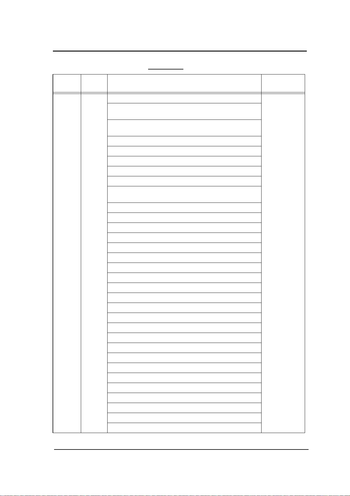
Rev. Table
Rev. for
Manual
00 - First Edition Jul. 21, 2005
01 - vi, 2-11, 2-12, 2-14, 2-16, 2-17, 2-20 - 2-22, 3-3, 3-5 - 3-30, 6-2,
02 - v(01), vi(02), viii(01) : Some headings and Page No. are modified. Nov. 17, 2005
Machine
Rev.
Page No. (Contents) Date
Sep. 15, 2005
6-5 - 6-41
Safety Summary-2(01) ~ Safety Summary-4(01) :
Some WARNING statements and CAUTION statements are
modified.
2-7(01) : Figure is changed.
2-11(02) : Figure is changed, and “Paper Color” is added.
2-12(02) : “HCF Tray Control” is added.
2-13(01), 2-14(02) : Contents are moved from previous page.
2-15(01) : “PCL” is added.
2-16(02) : Contents are moved from previous page.
2-17(02) : “Paper Color” is added.
2-18(01) : “HCF Tray Control” and “PCL” are added.
2-19(01) : Figure is corrected.
2-20(02) : Contents are moved from previous page.
2-21(02), 2-22(02) : “Language” is changed.
2-23(01) : Figure is changed, and “Configuration” is added.
2-24(01), 2-25(01) : Contents are moved from previous page.
2-26(01) : Page is added.
3-1(01), 3-3(02):
Title is changed to “Paper Size, Paper Weights, Paper Types and
Paper Color”.
3-5(02) : “Tracing Paper” is added.
3-6(02) : “Paper Color” is added.
3-7(02) ~ 3-30(02) : Contents are moved from previous page.
4-11(01) ~ 4-15(01) : Figure number is changed.
4-33(01) ~ 4-36(01) :
Procedure of step 8 ~ step 13 is modified, and a caution is added.
4-37(01) ~ 4-41(01) : Step number is changed.
4-42(01) ~ 4-59(01) : Contents are moved from previous page.
4-60(01) : Page is added.
5-7(01) : Add the notation for the HCF Tray Control.
6-2(02) : Language is changed.
Page 4
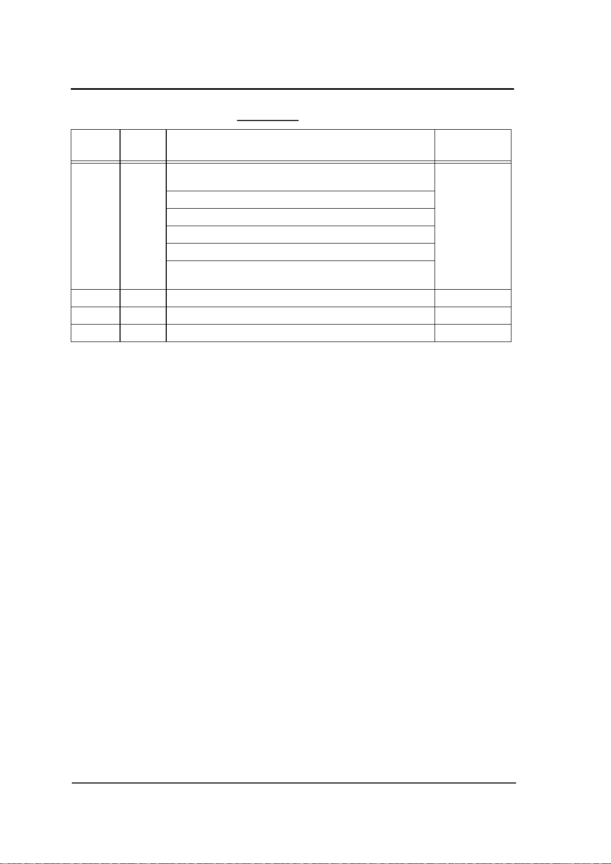
Rev. Table
Rev. for
Manual
02 - 6-4(01) : Figure is changed. Nov. 17, 2005
Machine
Rev.
Page No. (Contents) Date
6-5(02) : Language is changed, and Figure is changed.
6-6(02) : Figure is changed.
6-7(02) : “Error Information” is deleted.
6-8(02) : Contents of “Tray” is changed.
6-9(02) ~ 6-17(02) : Figure is changed.
6-18(02) : Contents of “Tray” is changed.
6-19(02) ~ 6-21(02) : Figure is changed, and explanation is modified.
6-22(02) : Explanation is added.
6-23(02), 6-24(02) : Figure is changed.
6-25(02) : Figure is changed, and explanation is modified.
6-26(02) ~ 6-28(02) : Figure is changed.
6-29(02), 6-30(02) : Figure is changed, and explanation is added.
6-31(02) : Explanation is added.
6-32(02) ~ 6-36(02) : Figure is changed, and explanation is added.
6-37(02) ~ 6-39(02) : Figure is changed.
6-40(02) : Contents are moved from previous page.
6-41(02) ~ 6-43(02) : Figure is changed.
6-44(02), 6-45(02) : Figure is changed, and explanation is added.
6-46(02), 6-47(01) : Figure is changed, and explanation is modified.
6-48(01) : Figure is changed, and explanation is added.
6-49(01) : Explanation is added.
6-50(01) : Figure is changed.
6-51(01), 6-52(01) : Figure is changed, and explanation is added.
6-53(01) ~ 6-56(01) : Contents are moved from previous page.
03 - TOC-1(02), TOC-2(03), TOC-3(01), TOC-4(02) :
Page Number of Table of Contents are changed.
Some headings and Page No. are modified.
Safety Summary-12(01) : Caution Plates are changed.
1-5(01) : Figure 1-2 is changed.
4-17(01) ~ 4-19(01) : Figures are changed.
4-31(01) : Figure 4-56 is changed.
4-33(02) : Figure and CAUTION statement are changed.
4-34(02) ~ 4-36(02) : Figures are changed.
4-51(02) : Add the cleaning items, and correct the misentry.
Feb. 4, 2006
Page 5
Rev. Table
Rev. for
Manual
03 - 4-55(02) : Figure 4-110 is changed, and misentries are corrected. Feb. 4, 2006
04 - TOC-1(03), TOC-2(04), TOC-3(02), TOC-4( 03):
Machine
Rev.
Page No. (Contents) Date
4-56(02), 4-57(02) : Misentries are corrected.
4-58(02), 4-59(02) : All contents of “Cleaning the paper guide of the
Fuser Unit” are added.
4-60(02), 4-61(02) : All contents of “Cleaning the paper guide of the
Discharger Unit” are added.
4-62(01) ~ 4-64(01) : Contents are moved from previous page.
Mar. 22, 2006
Some page number are modified.
Safety Summary-3(02), Safety Summary-4(02) :
Some caution statements are added.
SafetySummary-7(01) :
All contents are added.
SafetySummary-8(01) ~ SafetySummary-13(01) :
Contents are moved from previous page.
SafetySummary-14(01): Page is added.
1-9(01) : Caution statement is added.
2-6(01) : NOTE statement is added.
2-7(02) : Fugire 2-5 is changed.
2-10(01) : Network name is changed.
2-14(03) : “Exit Jam Recovery” is deleted.
“LPD Queuing” is modified.
2-16(03) : “Paper Size” is modified.
2-17(03) : “Paper Color” is modified.
2-18(02) : “Exit Jam Recovery” is deleted.
2-19(02) : NOTE Statement is added.
2-20(03) : Network name is changed.
“Exit Jam Recovery” is added.
2-21(03) : “Auto Online”, “Auto Backup Time” and “Output
Cascade” are added.
2-22(03) : Contents are moved from previous page.
2-23(03) : Network name is cahnged.
“Exit Jam Recovery”, “Auto Online”, “Auto Backup
Time” and “Output Cascade” are added.
“Note 8” is added.
2-24(02) ~ 2-26(02) : Contents are moved from previous page.
3-3(03) : “Letter Tab Stock “ and “A4 Tab Stock” are added.
3-6(03) : Custom color number is changed from 16 to 80.
3-14(03) : Contents are modified.
Page 6
Rev. Table
Rev. for
Manual
04 - 3-15(03) : All contents are added. Mar. 22, 2006
Machine
Rev.
Page No. (Contents) Date
3-16(03) : Figure 3-13 is changed.
3-17(03) : Figure 3-15, 3-16 are changed.
3-18(03) ~ 3-31(01) : Contents are moved from previous page.
3-32(01) : Page is added.
5-8(01) : Some statements are added.
5-9(01) : Contents are moved from previous page.
Table Number is changed.
5-10(01) : Contents are moved from previous page.
Corective action of “Insufficient Disk Space”
is modified.
5-24(01) : CAUTION Statement is added.
6-15(03) : Figure 6-12 is changed.
Network name is changed.
6-17(03) : Figure 6-14 is changed.
6-24(03) : Figure 6-19 is changed.
Custom color number is changed from 16 to 80.
6-28(03) : Contents are modified.
6-29(03) : “LPD Banner Page” is modified.
6-30(03) : Figure 6-25 is modified.
Contents of each option are modified.
6-31(03) : Contents of each option are modified.
“Paper Color”, “Rotation”, “Reverse Order” and “Job
Partial Page Print” are added.
6-33(03) : Figure 6-27 is changed.
“Paper Color” is deleted.
6-44(03) : Figure 6-38 is changed.
Contents of each option are modified.
“Auto Online” and “Output Cascade - ...” are added.
6-45(03) : “Use Time Server” is modified.
6-48(02) : Figure 6-42 is changed.
Network name is changed.
6-49(02) : “Host Name” and “DNS Server Address” are added.
6-50(02) ~ 6-52(02) : Figures are cahnged.
Network name is changed.
6-56(01) ~ 6-59(01) : All contents are added.
6-60(01) : Blank page is added.
Page 7
Rev. Table
Rev. for
Manual
05 - Cover sheet : “Reed and keep this manual” is added. Sep. 21, 2006
Machine
Rev.
Page No. (Contents) Date
Back of cover sheet : “TRADEMARK” is added.
“NOTICE TO USER” is modified.
TOC-2(05) ~ TOC-4(04) : Some headings and Page No. are
modified.
1-4(01) : Transit Pass Unit T ype 156 is added.
1-10(01) : Figure 1-9 is changed.
2-10(02) : “Usage - Click Charge Counter” is added.
2-14(04) : “Cover Insert Mode” is added.
2-16(04) : “Letter TAB LEF” and “A4 TAB LEF” are deleted.
2-18(03) : “Paper Output - Default Output” is modified.
“Options - Cover Insert Mode” is added.
3-3(04) : “Letter Tab Stock” and “A4 Tab Stock” are deleted.
3-14(04) : Table 3-4 and NOTE statement are modified.
3-15(04) : “Loading Tab Stock Paper” is deleted.
3-16(04) : Figure3-15 and 3-16 are changed.
3-17(04) ~ 3-30(04) : Pages are shifted.
3-31, 3-32 : Pages are deleted.
4-24(01) : Figure4-40 and Figure4-41 are changed.
4-27(01) : Figure4-46 is changed.
4-29(01) : Figure4-51 is changed.
4-31(02) : Figure4-55 is changed.
4-42(02) : Figure4-83 is changed.
4-48(02) : Figure4-98 is changed.
4-51(03), 4-52(02) : All contents are added.
4-53(02) : Interval of “Discharger, Detach Corotoron” is modified.
4-54(02) ~ 4-66(01) : Contents are moved from previous page.
5-8(02) : Some notations are modified.
5-12(02) : Error code “E011” is added.
5-13(02) : Some contents are shifted.
5-14(02) : Error codes “E064”, “E065” and “E067” are added.
5-15(02) : Some contents are shifted.
5-16(02) : Error Codes “E0B2” and “E0B3” are added.
5-17(02) : Error code “E0D0” is added.
5-18(02) ~ 5-23(02) : Some contents are shifted.
Page 8
Rev. Table
Rev. for
Manual
05 - 5-24(02) : Error codes “E1E0”, “E1E1”, “E1E2” and “E1E3” are
Machine
Rev.
Page No. (Contents) Date
added
6-8(03) : “Click Charge Counter” is added to “Usage”.
6-9(03), 6-11(03) : Figure and contents are modified for Post Device.
6-14(03) : Figure 6-11 and contents are modified.
6-31(04) : “Paper Output” is modified.
6-44(04) : Figure 6-38 is changed.
“Cover Insert Mode” is added.
Sep. 21, 2006
Page 9

Table of Contents
SAFETY SUMMARY. . . . . . . . . . . . . . . . . . . . . . . . . . . . . . . . . . . . . .Safety Summary-1
Introduction
About This Manual . . . . . . . . . . . . . . . . . . . . . . . . . . . . . . . . . . . . . . . . . . . . . . . . . . . . . . . . . . 0-1
Audience . . . . . . . . . . . . . . . . . . . . . . . . . . . . . . . . . . . . . . . . . . . . . . . . . . . . . . . . . . . . . . 0-1
Manual Conventions . . . . . . . . . . . . . . . . . . . . . . . . . . . . . . . . . . . . . . . . . . . . . . . . . . . . . 0-2
For More Information . . . . . . . . . . . . . . . . . . . . . . . . . . . . . . . . . . . . . . . . . . . . . . . . . . . . 0-2
Chapter 1. Printer Overview
What This Chapter Provides . . . . . . . . . . . . . . . . . . . . . . . . . . . . . . . . . . . . . . . . . . . . . . . . . . . 1-1
Printer Features . . . . . . . . . . . . . . . . . . . . . . . . . . . . . . . . . . . . . . . . . . . . . . . . . . . . . . . . . . . . . 1-2
I/O Configurations . . . . . . . . . . . . . . . . . . . . . . . . . . . . . . . . . . . . . . . . . . . . . . . . . . . . . . . 1-3
Operator Control Panel . . . . . . . . . . . . . . . . . . . . . . . . . . . . . . . . . . . . . . . . . . . . . . . . . . . 1-3
External View of the Printer . . . . . . . . . . . . . . . . . . . . . . . . . . . . . . . . . . . . . . . . . . . . . . . . . . . 1-4
Internal View of the Printer. . . . . . . . . . . . . . . . . . . . . . . . . . . . . . . . . . . . . . . . . . . . . . . . . . . . 1-5
Powering On the Printer . . . . . . . . . . . . . . . . . . . . . . . . . . . . . . . . . . . . . . . . . . . . . . . . . . . . . . 1-6
Powering Off the Printer. . . . . . . . . . . . . . . . . . . . . . . . . . . . . . . . . . . . . . . . . . . . . . . . . . . . . . 1-7
Clearing Error Conditions . . . . . . . . . . . . . . . . . . . . . . . . . . . . . . . . . . . . . . . . . . . . . . . . . 1-8
Space Required for Installation. . . . . . . . . . . . . . . . . . . . . . . . . . . . . . . . . . . . . . . . . . . . . . . . 1-10
Chapter 2. Control Panels
What This Chapter Provides . . . . . . . . . . . . . . . . . . . . . . . . . . . . . . . . . . . . . . . . . . . . . . . . . . . 2-1
Description of Control Panels . . . . . . . . . . . . . . . . . . . . . . . . . . . . . . . . . . . . . . . . . . . . . . . . . . 2-2
OCP Menu Icons and Buttons. . . . . . . . . . . . . . . . . . . . . . . . . . . . . . . . . . . . . . . . . . . . . . . . . . 2-3
Using the OCP Menus. . . . . . . . . . . . . . . . . . . . . . . . . . . . . . . . . . . . . . . . . . . . . . . . . . . . . . . . 2-4
Using the Option Button Menu . . . . . . . . . . . . . . . . . . . . . . . . . . . . . . . . . . . . . . . . . . . . . 2-4
Using the Ten Key Pad Menu. . . . . . . . . . . . . . . . . . . . . . . . . . . . . . . . . . . . . . . . . . . . . . . 2-5
Using the + / - Change Button Menu . . . . . . . . . . . . . . . . . . . . . . . . . . . . . . . . . . . . . . . . . 2-6
Using the Enable/Disable Change Button Menu . . . . . . . . . . . . . . . . . . . . . . . . . . . . . . . . 2-7
OCP Menu Structure. . . . . . . . . . . . . . . . . . . . . . . . . . . . . . . . . . . . . . . . . . . . . . . . . . . . . . . . . 2-8
Main Menu . . . . . . . . . . . . . . . . . . . . . . . . . . . . . . . . . . . . . . . . . . . . . . . . . . . . . . . . . . . . . 2-8
Information Menu. . . . . . . . . . . . . . . . . . . . . . . . . . . . . . . . . . . . . . . . . . . . . . . . . . . . . . . . 2- 9
Printer Menu. . . . . . . . . . . . . . . . . . . . . . . . . . . . . . . . . . . . . . . . . . . . . . . . . . . . . . . . . . . 2-11
Setup Menu. . . . . . . . . . . . . . . . . . . . . . . . . . . . . . . . . . . . . . . . . . . . . . . . . . . . . . . . . . . . 2-19
Reports Menu . . . . . . . . . . . . . . . . . . . . . . . . . . . . . . . . . . . . . . . . . . . . . . . . . . . . . . . . . . 2-24
Jobs Menu. . . . . . . . . . . . . . . . . . . . . . . . . . . . . . . . . . . . . . . . . . . . . . . . . . . . . . . . . . . . . 2-25
Sub Panel. . . . . . . . . . . . . . . . . . . . . . . . . . . . . . . . . . . . . . . . . . . . . . . . . . . . . . . . . . . . . . . . . 2-26
OG L
Table of Contents TOC-1
0 3
Page 10

Chapter 3. Paper Handling
What This Chapter Provides . . . . . . . . . . . . . . . . . . . . . . . . . . . . . . . . . . . . . . . . . . . . . . . . . . . 3-1
Paper . . . . . . . . . . . . . . . . . . . . . . . . . . . . . . . . . . . . . . . . . . . . . . . . . . . . . . . . . . . . . . . . . . . . . 3-2
Unacceptable Paper . . . . . . . . . . . . . . . . . . . . . . . . . . . . . . . . . . . . . . . . . . . . . . . . . . . . . . 3-2
Storing Paper . . . . . . . . . . . . . . . . . . . . . . . . . . . . . . . . . . . . . . . . . . . . . . . . . . . . . . . . . . . 3-2
Paper Sizes, Paper Weights, Paper Types and Paper Color . . . . . . . . . . . . . . . . . . . . . . . . . . . 3-3
Paper Size . . . . . . . . . . . . . . . . . . . . . . . . . . . . . . . . . . . . . . . . . . . . . . . . . . . . . . . . . . . . . . 3-3
Paper Size Indication . . . . . . . . . . . . . . . . . . . . . . . . . . . . . . . . . . . . . . . . . . . . . . . . . . . . . 3-4
Paper Weights. . . . . . . . . . . . . . . . . . . . . . . . . . . . . . . . . . . . . . . . . . . . . . . . . . . . . . . . . . . 3-5
Paper Type . . . . . . . . . . . . . . . . . . . . . . . . . . . . . . . . . . . . . . . . . . . . . . . . . . . . . . . . . . . . . 3-5
Loading Paper . . . . . . . . . . . . . . . . . . . . . . . . . . . . . . . . . . . . . . . . . . . . . . . . . . . . . . . . . . . . . . 3-7
Proper Paper Handling . . . . . . . . . . . . . . . . . . . . . . . . . . . . . . . . . . . . . . . . . . . . . . . . . . . . 3-7
Loading Paper in Tray . . . . . . . . . . . . . . . . . . . . . . . . . . . . . . . . . . . . . . . . . . . . . . . . . . . . 3-9
Loading Special Media. . . . . . . . . . . . . . . . . . . . . . . . . . . . . . . . . . . . . . . . . . . . . . . . . . . . 3-6
Setting the Non-Standard Paper Size . . . . . . . . . . . . . . . . . . . . . . . . . . . . . . . . . . . . . . . . . . . 3-15
Setting the Paper Weight Value . . . . . . . . . . . . . . . . . . . . . . . . . . . . . . . . . . . . . . . . . . . . . . . 3-19
Setting the HV Adjust Values. . . . . . . . . . . . . . . . . . . . . . . . . . . . . . . . . . . . . . . . . . . . . . . . . 3-21
Setting the Table Adjust . . . . . . . . . . . . . . . . . . . . . . . . . . . . . . . . . . . . . . . . . . . . . . . . . . . . . 3-23
Setting the Paper Moisture . . . . . . . . . . . . . . . . . . . . . . . . . . . . . . . . . . . . . . . . . . . . . . . . . . . 3-25
Preparing the Stacker . . . . . . . . . . . . . . . . . . . . . . . . . . . . . . . . . . . . . . . . . . . . . . . . . . . . . . . 3-27
Set the Basket into the Stacker . . . . . . . . . . . . . . . . . . . . . . . . . . . . . . . . . . . . . . . . . . . . . 3-27
Removing Paper . . . . . . . . . . . . . . . . . . . . . . . . . . . . . . . . . . . . . . . . . . . . . . . . . . . . . . . . . . . 3-28
Removing Paper from the Stacker . . . . . . . . . . . . . . . . . . . . . . . . . . . . . . . . . . . . . . . . . . 3-28
Chapter 4. Care and Maintenance
What This Chapter Provides . . . . . . . . . . . . . . . . . . . . . . . . . . . . . . . . . . . . . . . . . . . . . . . . . . . 4-1
Replacing Consumables . . . . . . . . . . . . . . . . . . . . . . . . . . . . . . . . . . . . . . . . . . . . . . . . . . . . . . 4-2
Adding Toner . . . . . . . . . . . . . . . . . . . . . . . . . . . . . . . . . . . . . . . . . . . . . . . . . . . . . . . . . . . 4-2
Replacing the Toner Bag . . . . . . . . . . . . . . . . . . . . . . . . . . . . . . . . . . . . . . . . . . . . . . . . . . 4-7
Replacing the Developer Mix . . . . . . . . . . . . . . . . . . . . . . . . . . . . . . . . . . . . . . . . . . . . . . 4-9
Replacing the Fuser Cleaning Web . . . . . . . . . . . . . . . . . . . . . . . . . . . . . . . . . . . . . . . . . 4-17
Replacing the Fine Filter . . . . . . . . . . . . . . . . . . . . . . . . . . . . . . . . . . . . . . . . . . . . . . . . . 4-20
Winding the OPC Sheet . . . . . . . . . . . . . . . . . . . . . . . . . . . . . . . . . . . . . . . . . . . . . . . . . . 4-22
Clearing Paper Jams . . . . . . . . . . . . . . . . . . . . . . . . . . . . . . . . . . . . . . . . . . . . . . . . . . . . . . . . 4-24
Regist Cover . . . . . . . . . . . . . . . . . . . . . . . . . . . . . . . . . . . . . . . . . . . . . . . . . . . . . . . . . . 4-25
Input Station Area. . . . . . . . . . . . . . . . . . . . . . . . . . . . . . . . . . . . . . . . . . . . . . . . . . . . . . . 4-27
Regist Station Area . . . . . . . . . . . . . . . . . . . . . . . . . . . . . . . . . . . . . . . . . . . . . . . . . . . . . 4-29
Paper Feed Area . . . . . . . . . . . . . . . . . . . . . . . . . . . . . . . . . . . . . . . . . . . . . . . . . . . . . . . . 4-31
Container Stacker . . . . . . . . . . . . . . . . . . . . . . . . . . . . . . . . . . . . . . . . . . . . . . . . . . . . . . 4-42
High Capacity Feeder (HCF) . . . . . . . . . . . . . . . . . . . . . . . . . . . . . . . . . . . . . . . . . . . . . . 4-48
Transit Pass Unit Type 156 . . . . . . . . . . . . . . . . . . . . . . . . . . . . . . . . . . . . . . . . . . . . . . . 4-51
Cleaning the Printer. . . . . . . . . . . . . . . . . . . . . . . . . . . . . . . . . . . . . . . . . . . . . . . . . . . . . . . . . 4-53
Cleaning the Printer Covers . . . . . . . . . . . . . . . . . . . . . . . . . . . . . . . . . . . . . . . . . . . . . . . 4-54
Cleaning Trays . . . . . . . . . . . . . . . . . . . . . . . . . . . . . . . . . . . . . . . . . . . . . . . . . . . . . . . . . 4-54
Cleaning the Container Baskets . . . . . . . . . . . . . . . . . . . . . . . . . . . . . . . . . . . . . . . . . . . . 4-55
Cleaning the Toner Bottle Joint . . . . . . . . . . . . . . . . . . . . . . . . . . . . . . . . . . . . . . . . . . . . 4-56
TOC-2 Table of Contents
OG L
0 5
Page 11

Cleaning the Discharger and the Detach Corotron. . . . . . . . . . . . . . . . . . . . . . . . . . . . . . 4-57
Clearing the Inverter Valve Piece. . . . . . . . . . . . . . . . . . . . . . . . . . . . . . . . . . . . . . . . . . . 4-58
Cleaning the paper guide of the Fuser Unit . . . . . . . . . . . . . . . . . . . . . . . . . . . . . . . . . . . 4-60
Cleaning the paper guide of the Discharger Unit. . . . . . . . . . . . . . . . . . . . . . . . . . . . . . . 4-62
Handling and Storing Supplies and Consumables . . . . . . . . . . . . . . . . . . . . . . . . . . . . . . . . . 4-64
Paper . . . . . . . . . . . . . . . . . . . . . . . . . . . . . . . . . . . . . . . . . . . . . . . . . . . . . . . . . . . . . . . . 4-64
Toner and Developer . . . . . . . . . . . . . . . . . . . . . . . . . . . . . . . . . . . . . . . . . . . . . . . . . . . . 4-65
Chapter 5. Troubleshooting
What This Chapter Provides . . . . . . . . . . . . . . . . . . . . . . . . . . . . . . . . . . . . . . . . . . . . . . . . . . . 5-1
Guidelines Flowchart . . . . . . . . . . . . . . . . . . . . . . . . . . . . . . . . . . . . . . . . . . . . . . . . . . . . . . . . 5-2
Basic Troubleshooting Tips . . . . . . . . . . . . . . . . . . . . . . . . . . . . . . . . . . . . . . . . . . . . . . . . . . . 5-3
General Printing Problems . . . . . . . . . . . . . . . . . . . . . . . . . . . . . . . . . . . . . . . . . . . . . . . . . . . . 5-4
Print Quality Problems . . . . . . . . . . . . . . . . . . . . . . . . . . . . . . . . . . . . . . . . . . . . . . . . . . . . . . . 5-6
Duplex Printing Problems. . . . . . . . . . . . . . . . . . . . . . . . . . . . . . . . . . . . . . . . . . . . . . . . . . . . . 5-6
Printer Notice . . . . . . . . . . . . . . . . . . . . . . . . . . . . . . . . . . . . . . . . . . . . . . . . . . . . . . . . . . . . . . 5-7
OCP Display Messages. . . . . . . . . . . . . . . . . . . . . . . . . . . . . . . . . . . . . . . . . . . . . . . . . . . . . . . 5-9
Printer Status Message . . . . . . . . . . . . . . . . . . . . . . . . . . . . . . . . . . . . . . . . . . . . . . . . . . . . 5-9
Printer Warning Message . . . . . . . . . . . . . . . . . . . . . . . . . . . . . . . . . . . . . . . . . . . . . . . . . 5-11
Printer Error Message. . . . . . . . . . . . . . . . . . . . . . . . . . . . . . . . . . . . . . . . . . . . . . . . . . . . 5-11
Chapter 6. Web Utilities
What This Chapter Provides . . . . . . . . . . . . . . . . . . . . . . . . . . . . . . . . . . . . . . . . . . . . . . . . . . . 6-1
Overview. . . . . . . . . . . . . . . . . . . . . . . . . . . . . . . . . . . . . . . . . . . . . . . . . . . . . . . . . . . . . . . . . . 6-1
Access and Security . . . . . . . . . . . . . . . . . . . . . . . . . . . . . . . . . . . . . . . . . . . . . . . . . . . . . . 6-3
Accessing the Web Utilities . . . . . . . . . . . . . . . . . . . . . . . . . . . . . . . . . . . . . . . . . . . . . . . . 6-4
Web Page Organization . . . . . . . . . . . . . . . . . . . . . . . . . . . . . . . . . . . . . . . . . . . . . . . . . . . 6-5
Manage Status Options . . . . . . . . . . . . . . . . . . . . . . . . . . . . . . . . . . . . . . . . . . . . . . . . . . . . . . . 6-8
Status-General . . . . . . . . . . . . . . . . . . . . . . . . . . . . . . . . . . . . . . . . . . . . . . . . . . . . . . . . . . 6-9
Status-Tray . . . . . . . . . . . . . . . . . . . . . . . . . . . . . . . . . . . . . . . . . . . . . . . . . . . . . . . . . . . . 6-10
Status-Paper Output . . . . . . . . . . . . . . . . . . . . . . . . . . . . . . . . . . . . . . . . . . . . . . . . . . . . . 6-11
Status-Consumables . . . . . . . . . . . . . . . . . . . . . . . . . . . . . . . . . . . . . . . . . . . . . . . . . . . . . 6-12
Status-Errors. . . . . . . . . . . . . . . . . . . . . . . . . . . . . . . . . . . . . . . . . . . . . . . . . . . . . . . . . . . 6-13
Status-Usage . . . . . . . . . . . . . . . . . . . . . . . . . . . . . . . . . . . . . . . . . . . . . . . . . . . . . . . . . . . 6-14
Status-Network . . . . . . . . . . . . . . . . . . . . . . . . . . . . . . . . . . . . . . . . . . . . . . . . . . . . . . . . . 6-15
Status-Report . . . . . . . . . . . . . . . . . . . . . . . . . . . . . . . . . . . . . . . . . . . . . . . . . . . . . . . . . . 6-16
Status-Revision. . . . . . . . . . . . . . . . . . . . . . . . . . . . . . . . . . . . . . . . . . . . . . . . . . . . . . . . . 6-17
Manage System Options . . . . . . . . . . . . . . . . . . . . . . . . . . . . . . . . . . . . . . . . . . . . . . . . . . . . . 6-18
System-General . . . . . . . . . . . . . . . . . . . . . . . . . . . . . . . . . . . . . . . . . . . . . . . . . . . . . . . . 6-19
System-Tray . . . . . . . . . . . . . . . . . . . . . . . . . . . . . . . . . . . . . . . . . . . . . . . . . . . . . . . . . . . 6-21
System-Paper Output . . . . . . . . . . . . . . . . . . . . . . . . . . . . . . . . . . . . . . . . . . . . . . . . . . . . 6-26
System-Virtual Printer . . . . . . . . . . . . . . . . . . . . . . . . . . . . . . . . . . . . . . . . . . . . . . . . . . . 6-27
System-Accounting . . . . . . . . . . . . . . . . . . . . . . . . . . . . . . . . . . . . . . . . . . . . . . . . . . . . . 6-37
System-Jobs . . . . . . . . . . . . . . . . . . . . . . . . . . . . . . . . . . . . . . . . . . . . . . . . . . . . . . . . . . . 6-38
System-Serial Number . . . . . . . . . . . . . . . . . . . . . . . . . . . . . . . . . . . . . . . . . . . . . . . . . . . 6-39
Manage Configuration Options. . . . . . . . . . . . . . . . . . . . . . . . . . . . . . . . . . . . . . . . . . . . . . . . 6-40
OG L
Table of Contents TOC-3
0 3
Page 12

Configuration-General . . . . . . . . . . . . . . . . . . . . . . . . . . . . . . . . . . . . . . . . . . . . . . . . . . . 6-41
Configuration-Events . . . . . . . . . . . . . . . . . . . . . . . . . . . . . . . . . . . . . . . . . . . . . . . . . . . . 6-42
Configuration-Configuration . . . . . . . . . . . . . . . . . . . . . . . . . . . . . . . . . . . . . . . . . . . . . . 6-43
Configuration-Communication. . . . . . . . . . . . . . . . . . . . . . . . . . . . . . . . . . . . . . . . . . . . . 6-48
Using the Accounting File . . . . . . . . . . . . . . . . . . . . . . . . . . . . . . . . . . . . . . . . . . . . . . . . . . . 6-53
Accounting Slip Sheet. . . . . . . . . . . . . . . . . . . . . . . . . . . . . . . . . . . . . . . . . . . . . . . . . . . . . . . 6-56
Appendix A . Specifications
What This Appendix Contains . . . . . . . . . . . . . . . . . . . . . . . . . . . . . . . . . . . . . . . . . . . . . . . . .A-1
Specifications . . . . . . . . . . . . . . . . . . . . . . . . . . . . . . . . . . . . . . . . . . . . . . . . . . . . . . . . . . . . . .A-2
Base Printer. . . . . . . . . . . . . . . . . . . . . . . . . . . . . . . . . . . . . . . . . . . . . . . . . . . . . . . . . . . . .A-2
Consumables. . . . . . . . . . . . . . . . . . . . . . . . . . . . . . . . . . . . . . . . . . . . . . . . . . . . . . . . . . . .A-3
Append ix B. Pa per S pecifications
Media Guidelines . . . . . . . . . . . . . . . . . . . . . . . . . . . . . . . . . . . . . . . . . . . . . . . . . . . . . . . . . . .B-1
General Media Recommendations . . . . . . . . . . . . . . . . . . . . . . . . . . . . . . . . . . . . . . . . . . .B-1
Paper Specifications . . . . . . . . . . . . . . . . . . . . . . . . . . . . . . . . . . . . . . . . . . . . . . . . . . . . .B-2
Paper Weight . . . . . . . . . . . . . . . . . . . . . . . . . . . . . . . . . . . . . . . . . . . . . . . . . . . . . . . . . . .B-3
Paper Color . . . . . . . . . . . . . . . . . . . . . . . . . . . . . . . . . . . . . . . . . . . . . . . . . . . . . . . . . . . .B-3
Paper Composition . . . . . . . . . . . . . . . . . . . . . . . . . . . . . . . . . . . . . . . . . . . . . . . . . . . . . . B-4
Paper Cut . . . . . . . . . . . . . . . . . . . . . . . . . . . . . . . . . . . . . . . . . . . . . . . . . . . . . . . . . . . . . .B-4
Paper Smoothness . . . . . . . . . . . . . . . . . . . . . . . . . . . . . . . . . . . . . . . . . . . . . . . . . . . . . . .B-4
Paper Fusing . . . . . . . . . . . . . . . . . . . . . . . . . . . . . . . . . . . . . . . . . . . . . . . . . . . . . . . . . . .B-4
Moisture . . . . . . . . . . . . . . . . . . . . . . . . . . . . . . . . . . . . . . . . . . . . . . . . . . . . . . . . . . . . . . . B-5
Paper Curl . . . . . . . . . . . . . . . . . . . . . . . . . . . . . . . . . . . . . . . . . . . . . . . . . . . . . . . . . . . . .B-6
Recycled Paper . . . . . . . . . . . . . . . . . . . . . . . . . . . . . . . . . . . . . . . . . . . . . . . . . . . . . . . . .B-7
Grain Direction . . . . . . . . . . . . . . . . . . . . . . . . . . . . . . . . . . . . . . . . . . . . . . . . . . . . . . . . .B-7
Paper Smoothness . . . . . . . . . . . . . . . . . . . . . . . . . . . . . . . . . . . . . . . . . . . . . . . . . . . . . . .B-7
Special Media . . . . . . . . . . . . . . . . . . . . . . . . . . . . . . . . . . . . . . . . . . . . . . . . . . . . . . . . . . . . . .B-8
Preprinted Paper . . . . . . . . . . . . . . . . . . . . . . . . . . . . . . . . . . . . . . . . . . . . . . . . . . . . . . . .B-8
Prepunched Paper . . . . . . . . . . . . . . . . . . . . . . . . . . . . . . . . . . . . . . . . . . . . . . . . . . . . . .B-10
Adhesive Labels . . . . . . . . . . . . . . . . . . . . . . . . . . . . . . . . . . . . . . . . . . . . . . . . . . . . . . .B-12
Perforated Paper . . . . . . . . . . . . . . . . . . . . . . . . . . . . . . . . . . . . . . . . . . . . . . . . . . . . . . . B-15
Printing Guidelines . . . . . . . . . . . . . . . . . . . . . . . . . . . . . . . . . . . . . . . . . . . . . . . . . . . . . . . . .B-17
Printable Area . . . . . . . . . . . . . . . . . . . . . . . . . . . . . . . . . . . . . . . . . . . . . . . . . . . . . . . . .B-17
Preprinted Lines . . . . . . . . . . . . . . . . . . . . . . . . . . . . . . . . . . . . . . . . . . . . . . . . . . . . . . . .B-18
Preprint Inhibited Area . . . . . . . . . . . . . . . . . . . . . . . . . . . . . . . . . . . . . . . . . . . . . . . . . . .B-18
Glossary
TOC-4 Table of Contents
OG L
0 4
Page 13
SAFETY SUMMARY
General Safety Guidelines
Before operating the machine, read the following instructions carefully:
■ Allow all the operating procedures provided in this manual.
■ Pay special attention to and follow all the hazard warning on the machine and in
the manual. Failure to do so can cause injury to yourself or damage to the
machine.
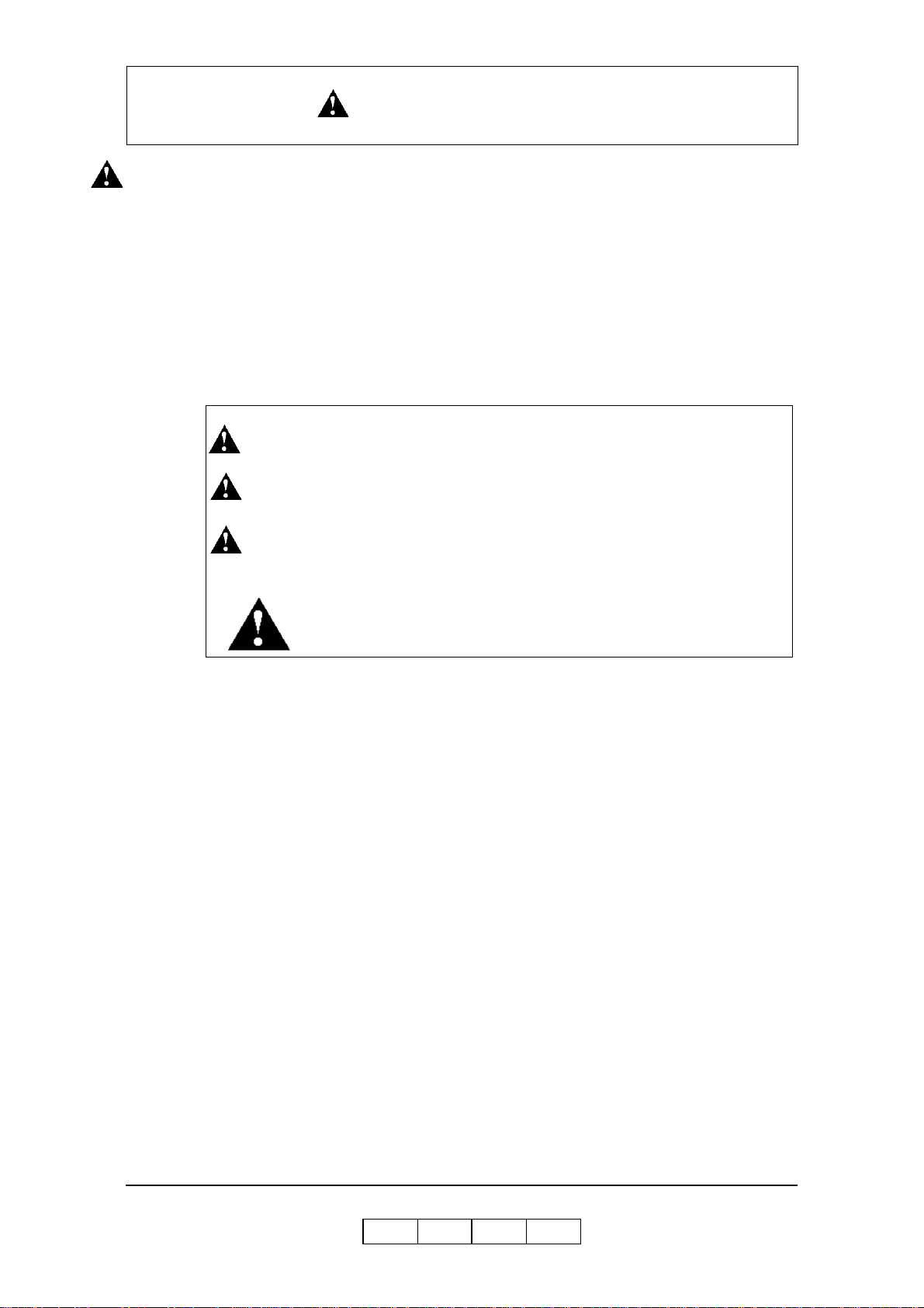
■ The hazard warnings which appear on the warning labels on the machine or in the
manual have one of the following alert headings consisting of an alert symbol and
a signal ward, DANGER, WARNING, or CAUTION.
DANGER! : indicates an imminently hazardous situation which, if not avoided,
will result in death or serious injury.
WARNING!: indicates a potentially hazardous situation which, if not avoided,
can result in death or serious injury.
CAUTION!: indicates a hazardous situation which, if not avoided, will or can
result in minor or moderate injury, or serious damage of product.
The alert symbol shown left precedes every signal word for hazard
warnings, and appears in safety related descriptions in the manual.
The signal word ’NOTE’ is used to present warnings which are not directly related to
personal injury hazards.
■ Do not perform any operation or action in any way other than as provided in this
manual. When in doubt, call the designated field engineer.
■ Keep in mind that the hazard warnings in this manual or on the machine cannot
cover every possible case, as it is impossible to predict and evaluate all
circumstances beforehand. Be alert and use your common sense.
OG L
Safety Summary -1
0 0
Page 14
SAFETY SUMMARY
Hazard Warning Statements
WARNING Statement
■ “Use of controls, adjustments or pe rformance of procedures ot her than those
specified in this manual may result in hazardous laser radiation exposure.” on
page S afe ty Sum mary-5
■ “Connect the power plug only to a properly rated power outlet. Otherwise, a fire
or shock hazard may resul t.” on page Safety Summary- 8
■ “Never use multi-plug adaptors to plug multiple power plugs into the same power
source. Be sure to operate the printer on a sole-use receptacle. Multiple
connectors can cause overheating and a fire could result.” on page Safety
Summary-8
■ “The pri nter must be connected to the gro unding power outlet for safe and proper
operation.” on page Safety Summary-8
■ “Apparatet må kun tilkoples jordet stikkontakt.” on page Safety Summary-8
■ “Apparaten skall ansulatas till jordat uttag när den ansluts till ett nätverk.” on
page S afe ty Sum mary-8
■ “Für einen sicheren und ordnungsgemäßen Betrieb muß der Drucker an eine
geerdete Steckdose angeschlossen werden.” on page Safety Summary-8
■ “Do not throw the toner bottle into a fire because it may suddenly burn, causing a
risk of fire or personal injury.” on page 4-6
■ “Dispose the toner bottle as incombustible waste.” on page 4-6
■ “Waste materials should be disposed of or incinerated under conditions which
meet all federal, state and local environmental regulations. Since regulations may
vary from one region to another, check with the agency that governs waste
disposal i n your area for proper procedures.” on page 4-8
■ “Do not throw the developer bottle into a fire because it may suddenly burn,
causing a risk of fire or personal injury.” on page 4-16
■ “The Fuser Unit is very hot. Do not touch any parts of the Fuser Unit ex cept those
parts which are used to replace the Fuser Cleaning Web.” on page 4-17
■ “The Fuser Unit is very hot. Do not touch any parts of the Fuser Unit ex cept those
parts which are used to remove the paper. It is better to use the Bamboo Tweezers
to remove the paper. (The Bamboo Tweezers is an attached accessory.)” on page
4-35
CAUTION Statement
■ “Never unplug or rep lug the printer while it is on.” on page Safety Summa ry-9
■ “Do not place the printer near heaters or volatile, flammable, or combustible
materials.” on page Safety Summary-10
Safety Summary -2
OG L
0 1
Page 15

SAFETY SUMMARY
■ “Once the printer is powered off, wait at least 5 seconds to next power on.” on
page 1-6
■ “If the message “Open the Fuser cover, and check that there is no paper” is
displayed on the OCP, open the Fuser cover and check the Fuser unit refer to
Chapter 4.” on page 1-9
■ “If the printer does not power on, power off the printer, wait at least 30 seconds,
then power on the printer again.” on page 1-6
■ “You must set the correct paper weight value. The incorrect paper weight value
may cause pa per jam.” on page 3-20
■ “Depending on amount of paper, the Basket is very heavy. Take care not to hurt
your back when lifting a heavy Basket.” on page 3-30
■ “Toner is not harmful to the human body, but if some toner has come in contact
with your skin or clothes, you should wash it immediately with cold water.” on
page 4-3
■ “The toner is not harmful to the human body . However, take care not to inhale or
swallow it because you may feel sick. ” on page 4-6
■ “If the toner goes into your eyes, immediately rinse with running water. If
affected eyes are not rinsed, it may become injured. If the skin or clothing is
contacted, wash with soap and water” on page 4-6
■ “Hold the developer bottle when you turn the cap so that the bottle is not turned
together with the cap.” on page 4-10
■ “Hold the developer bottle when you turn the cap so that the bottle is not turned
together with the cap.” on page 4-13
■ “Incorrect setting of the Developer Bottle cause damage to the Developer Unit.
Make sure the setting of the Developer Bottle before go to next step.” on page 413
■ “If the developer is spilled out on the floor, the floor becomes very slippy. This
may result in a fall and/or injury. Clean up the spilled developer with a toner-safe
vacuum cleaner.” on page 4-15
■ “If the developer goes into your eyes, immediately rinse with running water. If
affected eyes are not rinsed, it may become injured. If the skin or clothing is
contacted, wash with soap and water” on page 4-15
■ “Surface of the Photoconductor Drum (OPC Sheet) is very sensitive. Carefully
remove a paper to avoid scratch the surface of the Photoconductor Drum.” on
page 4-32
■ “The paper i n the Fus er Unit mu st be re moved by step 8 to step 14 wh en the Fuse r
Jam is happened. If the paper remains in the Fuser Unit, paper is scorched, or it
causes an other paper jam, or it causes some mechanical damage.” on page 4-33
■ “Incompletion of closing the Fuser Unit Cover and the Paper Guide cause damage
to the Fuser Unit. Make sure the Fuser Unit Cover and the Paper Guide are
completely closed.” on page 4-36
■ “Power off the printer prior to cleaning.” on page 4-51
Safety Summary -3
OG L
0 2
Page 16

SAFETY SUMMARY
■ “Do not use solvent on the printer. Using solvent may dissolve the plastic and
paint of t he printer.” on page 4-51
■ “Do not use c leaning solut i ons to clean inside and around the printe r. Use only a
water-moistened cloth.” on page 4-51
■ “For cleaning up toner or developer spillage, use a specially-designed toner-safe
vacuum cleaner. If you use a regular vacuum cleaner, the drawn toner/developer
powder may scatter in the air. If you inhale or your eyes come into contact with
such powder, you may feel sick or injure your eyes. Further, the drawn toner/
developer powder may render the vacuum cleaner defective when it enters the
vacuum cleaner’s motor section.” on page 4-51
■ “The Paper Height Sensor in the Tray is sensitive. Carefully cleaning a Tray to
avoid a damage to the Paper Height Sensor.” on page 4-52
■ “If the message “Open the Fuser cover, and check that there is no paper” is
displayed with E31x Call for Service error, open the Fuser cover and check the
Fuser unit refer to Chapter 4.” on page 5-24
■ “Do not use paper that contains CaCO3 as it can drastically reduce fuser life.” on
page B-4
■ “Adhesive that comes in contact with the printer may contaminate the
photoconductor and the internal printer mechanism. To test label stock for
adhesive exposure, press a sheet of plain paper against a sheet of label stock. The
plain pap er should not adhere to the label stock at all.” on page B-12
Safety Summary -4
OG L
0 2
Page 17
Laser Safety
This printer is certified as a Class 1 laser pr oduct under the U.S. Department of Health
and Human Services (DHHS) Radiation Performance Standard according to the
Radiation Control for Health and Safety Act of 1 968. Th is means that the printer does
not emit hazardous laser radiation.
Since radiation emitted inside the printer is completely confined within the protective
housings and external covers, the laser beam cannot escape from the machine during
any phase of user operation.
The Center for Devices and Radiological Health (CDRH) of the U.S. Food and Drug
Administration implemented regulations for laser products on August 1976. These
regulations apply to laser products marketed in the United States. The label on the
printer indicates compliance with the CDRH regulations and must be attached to laser
products marketed in the United States.
This printer is classified as a Class 1 laser product both under EN60825 and the Code
of Federal Regulations, 1040.10 of Title 21.
SAFETY SUMMARY
LOUKAN 1 LASERLAITE
CLASS 1 LASER APPARA T
Internal Laser Radiation
Maximum Radiation Power: 10mW x 4 diodes
Wave Lengt h: 780nm
WARNING!
Use of controls, adju st ments or perform ance of procedures other than
those specified in this manual may result in hazardou s laser radiation
exposure.
OG L
Safety Summary -5
0 0
Page 18

Certifications
FCC Notice
This equipment has been tested and found to comply with the limits for a Class A
digital device pursuant to Part 15 of FCC Rules. These limits are designed to provide
reasonable protection against harmful interference when the equipment is operated in
a commercial environment. This equipment generates, uses, and can radiate radio
frequency energy and, if not installed and used in accordance with this user’s guide,
may cause harmful interference to radio communications. Operation of this equipment
in a residential area is likely to cause harmful interference. If this occurs, users are
required to correct the interference at their own expense.
Use of shielded cables is required to comply with Class A limits in Subpart B of
Part 15 of FCC Rules.
Do not make any changes or modifications to the equipment other than those specified
in this user’s guide.
You may find the following booklet prepared by the Federal Communications
Commission helpful: How to Identify and Resolve Radio - TV Interference Problems.
This booklet is available from the U.S. Government Printing Office, Washington, D.C.
20402, Stock N o. 00 4- 000-00345-4.
SAFETY SUMMARY
Canadian Certification
This Class A digital apparatus complies with Canadian ICES-003.
Cet appareil numérique de la classe A est conforme à la norme NMB-003 du Canada.
VCCI Notice (Japan)
This is a class 1 product based on the standard of the Voluntary Control Council for
Interference by Information Technology Equipment (VCCI). If this equipment is used
in a domestic environment, radio disturbance may arise. When such trouble occurs, you
may be required to take corrective actions.
Safety Summary -6
OG L
0 0
Page 19

SAFETY SUMMARY
Declaration of Conformity for Safety/EMI
The Printer, High Capacity Feeder and Container Stacker conform to the directives and
standards shown below . For further information or to request a copy of the Declaration
of Confor mity, contac t your Distri butor.
1. EMC directive 89/336/EEC, 92/31/EEC
Emission:EN 55022 (Class A) / 1998 / A1: 2000 / A2: 2003
EN61000-3-2: 2001
EN61000-3-3 / 1995 / A1 : 2001
Immunity:EN55024 / 1998 / A1: 2001 / A2: 2003
IEC6100 0-4-2 / 1995/A1:1998 / A2: 2001
IEC61000-4-3 / 2002
IEC61000-4-4 / 1995 / A1:2000 / A2: 2001
IEC6100 0-4-5 / 1995 / A1: 2001
IEC6100 0-4-6 / 1996/ A1: 2001
IEC6100 0-4-8 / 1993 / A1: 2000
2. Low Voltage Directive 73/23/EEC incl. Amendments:
EN60950:1: 2001
EN60825-1:1993 / A1: 1997 / A2: 2001
3. CE Marking Directive 93/68/EEC
This equipment has been tested and found to comply with the limits for a class A
Information Technology Equipment in accordance with the European Standard
EN55022.
These limits are designed to provide reasonable protection against unacceptable
interference in either commercial or industrial environments. This equipment
generates, uses, and can radiate radio signals and if it is not installed and used in
accordance with the instructions detailed in this user’s guide, it may cause unacceptable
interference to radio communication installations and equipment. The operation of this
equipment in a residential area is likely to cause unacceptable interference in which
case you may be required to correct the source of the interference at your own expense.
In order to maintain compliance to the class A regulations, shielded cables must be used
with this equipment. Operation of this equipment without shielded cables is likely to
cause interference to radio and television receivers thereby degrading their reception.
Please be aware that changes and modifications made to the equipment without prior
approval of the manufacturer could negate your permission to operate the equipment.
Declaration of Conformity for RoHS
The Printer, High Capacity Feeder, and Container Stacker conform to the directives and
standards shown below . For further information or to request a copy of the Declaration
of Confor mity, contac t your Distri butor.
1. Restriction of Hazardous Substances (RoHS) Directive2002/95/EC
Safety Summary -7
OG L
0 1
Page 20
SAFETY SUMMARY
When Installing and Relocating the Printer
Power Specifications
Power Cords
WARNING!
Connect the power plug only to a properly rated power outlet. Otherwise,
a fire or shock hazard may result.
Never use multi-plug adaptors to plug multiple power plugs into the same
power source. Be sure to operate the printer on a sole-use receptacle.
Multiple connectors can cause overheating and a fire could result.
Ensure that the plug connection is free of dust. In a damp environment, a contaminated
connector can draw a non-negligible amount of current that can generate heat and
eventually cause a fire over an extended period of time.
To prevent the risk of electric shocks and personal injury, fire, and printer damage:
■ Always use the power cord provided with your printer. When an extension power
cord is required, always use a properly rated cord.
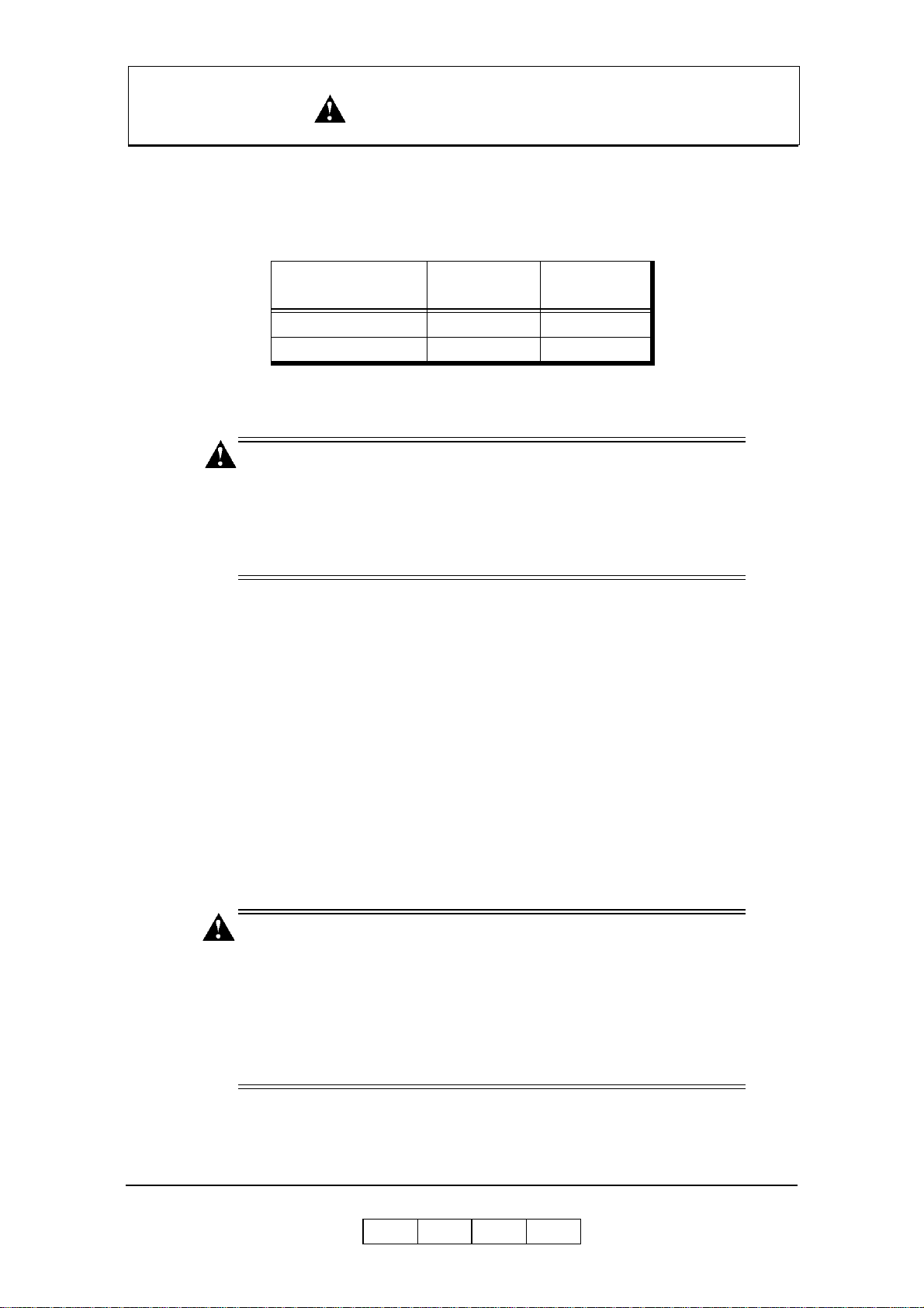
Rated Voltage
200/208/220/230/240V 50/60Hz 21A
380/400/415V 50/60Hz 21A
Rated
Frequency
Rated Current
If the power cord is not provided, use the following types of power cords:
❒ For North America:
❒ For Europe
WARNING!
The printer must be connected to the grounding power outlet for safe and
proper operation.
Apparatet må kun tilkoples jordet stikkontakt.
Apparaten skall ansulatas till jordat uttag när den ansluts till ett nätverk.
Für einen s i cheren und ordnungsgemäßen Betrieb muß der Drucker an
eine geerdete Steckdose angeschlossen werden.
Safety Summary -8
2
4 wires, Type SJT 4x12 AWG (4x4.0 mm
) or thicker
Rated min. 30 0V/ 2 5A (w it h gr ounding plu g) .
5 wires, min. 5x4.0 mm
2
Harmoni zed (<HAR>), Rated mi n. 300V/25A (with grounding plug).
OG L
0 1
Page 21

SAFETY SUMMARY
■ Do not attempt to rework, pull, bend, chafe, or otherwise damage the power cord.
Do not place a heavy object on the cord.
■ Never touch a power cord with wet hands.
■ If your printer produces smoke, excessive heat, unusual noises or odors, or if any
liquid is spilled into the printer, immediately switch off and unplug the printer.
■ If the power cord is broken or insulated wires are exposed, be sure to get them
replaced. (Do not use the damaged cord.)
CAUTION!
Never unplug or replug the printer while it is on.
■ When unplugging the printer, grasp the plug instead of the cord.
■ Be sure to switch off and unplug the printer before accessing its interior for
cleaning or maintenance.
■ When the printer is not used over an extended period of time, switch it off and
unplug it.
■ Once a month, unplug the printer and check that:
❒ t he power cord is plugged firmly into a receptacle.
❒ t he power cord is not cracked or frayed.
❒ t he plug is not excessively heated, rusted, or bent.
❒ t he plug and receptacle are free of dust.
NOTE:
If you notice any unusual conditions, contact your service representative.
OG L
Safety Summary -9
0 1
Page 22

SAFETY SUMMARY
Position in g the Printer Saf el y
To prevent the risk of electric shocks and personal injury, fire, and printer damage:
■ Switch off the printer before connecting the interface cable or optional accessory.
CAUTION!
Do not place the printer near heaters or volatile, flammable, or
combustible materials.
■ Place the printer on a level and sturdy surface that can withstand the printer’s
weight. If tilted, the printer may fall over and cause injuries.
■ Do not place the printer in a hot, humid, dusty , or poorly ventilated environment.
■ When moving the printer, be sure to unplug the power cord from the outlet. If the
printer is moved with the power cord connected, it can cause damage to the cord.
■ When moving the printer, do not tilt it more than 10 degrees. If tilted excessively,
the printer may fall over and cause injuries.
■ If you need to move the printer over a long distance, consult your Technical
Representative.
Environmental Limit
■ The printer is capable of operating normally within the following recommended
environmental limits:
❒ Temperature range: 60°-89°F (16°-32°C).
❒ Humidity range: 20-80% RH ( no condensation).
NOTE:
Sudden temperature fluctuations can affect print quality. Rapid heating of
a cold room can cause condensation inside the printer, directly interfering
with image transfer.
■ Do not expose the printer to direct sunlight, or the printer's performance may
decline.
Safety Summary -10
OG L
0 1
Page 23

SAFETY SUMMARY
Operating Precaution s
■ Take care not to allow ties, sleeves, shirts, or long hair to be caught in the printer
while operating.
■ Be careful not to touch the hazardous parts near the caution labels.
■ Be sure to avoid accidentally powering on the printer or pressing switches on the
operator’s panel while operating the printer.
■ Never touch the high voltage portions of the printer, where caution labels are
attached, when the printer is on. It may cause personal injuries if accidentally
touched.
■ Make sure that the printer paper complies with the supplies specifications.
Printing on paper which does not comply with the specifications may result in
paper jams and print quality degradation.
■ Properly load the paper into the hopper to prevent paper skew and paper jams.
■ It is absolutely necessary to follow the procedures and instructions described in
this manual in order to optimize the printer’s performance and to assure its safe
operation.
OG L
Safety Summary -11
0 1
Page 24

SAFETY SUMMARY
SAFETY PREC A U T I O NS
■ Always keep the area around the printer tidy. Use the printer under the proper
lighting (500-1,000 lux.). Keep sufficient space around the printer so the hoppers
can be pulled forward. Space required in the vicinity of the printer is as follows:
Front side: 1 meters
Left, right and rear side: 1 meter
■ Do not place anything on the printer.
■ Do not open any covers during printing operation. It may cause personal injuries
if moving elements or electrical parts are accidentally touched.
■ Be particularly careful when working in the fuser unit area. Do not touch the
inside of the fuser unit. The fuser unit becomes very hot (approx. 374°F [190°C])
and it may cause personal injuries if accidentally touched.
■ Toner and de veloper are comprised of powdery particles. Avoid inhaling to ner or
developer when it accidentally spills and circulates. If it spills on the floor,
immediately clean it with water-damped cloth. Do not leave it on the floor. I t may
cause accidents if stepped on as they are slippery beads of metal.
■ Limit your operations to those described in this manual. Contact the field engineer
or service technician for further operations which are not explained in this
manual.
■ This equipment generates ozone. Long-term exposure should be limited to 0.1
ppm calculated as an 8 hr. time weighted average concentration. Provide proper
ventilation. Avoid installing the unit in a small room (smaller than 27cubic
meter). If installing in a space smaller than 27cubic meter, frequent ventilation is
necessary
Safety Summary -12
OG L
0 2
Page 25
SAFETY SUMMARY
Care of Printer Supplies
■ Store the paper, toner , and other supplies in a place free from direct sunlight and
away from any heating apparatus. Keep them in a dry, cool, clean environment.
■ Store paper that has been removed from its wrapper, but not loaded into the
drawer, in a sealed, plastic bag in a cool, dark place.
■ If your hands become soiled with toner, wash them with soap and water
immediately.
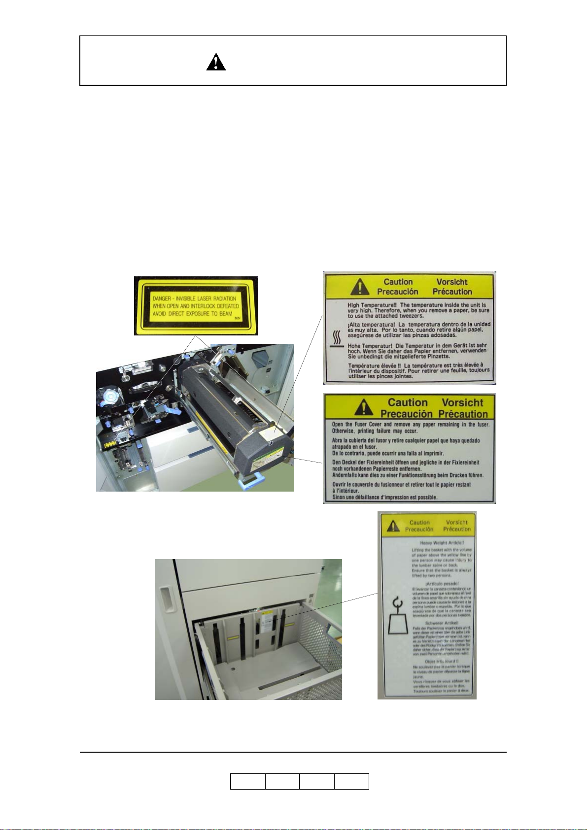
Caution Labels
Following figure shows the caution labels affixed on the printer.
OG L
Safety Summary -13
0 1
Page 26

SAFETY SUMMARY
Blank
Safety Summary -14
OG L
0 1
Page 27

About This Manual
This manual provides easy access to the information you need to operate the 156PPM
(Pages Per Minute) laser printer.
NOTE:
This User’s Guide is intended to be viewed online. When viewing it online,
use the bookmarks and page reference links for easy navigation
throughout the do c ume n t .
To find out about a specific topic, refer to:
■ SAFETY SUMMARY – For safety information and printer characteristics,
including environmental and electrical requirements.
■ Chapter 1: Printer Overview – For printer components and features.
■ Chapter 2: Operator Control Panel – To access and use the liquid crystal display
(LCD) window and the menus screens.
■ Chapter 3: Paper Handling – For media recommendations and paper handling
procedures.
Introduction
Audience
This manual is written for those persons responsible for operating the printer. A basic
understanding of computer equipment and its operations is required.
■ Chapter 4: Care and Maintenance – For detailed instructions on replacing
consumables, clearing paper jams, and cleaning and maintaining the printer.
■ Chapter 5: Troubleshooting – For information on printing problems and printer
error and warning messages .
■ Chapter 6: Web Utilities – For information on accessing the printer via the
Internet or your company’s Intranet.
■ Appendix A: Specifications – For printer specifications.
■ Appendix B: Paper Specifications – For media specifications and printing
guidelines.
■ Glossary – For definitions of terms and acronyms.
OG L
Introduction 0-1
0 0
Page 28
Manual Conventions
The following conventions are used in this manual:
■ Bold and Italics are used sparingly for emphasis.
■ Information you e n ter: Looks Like This.
■ Key Names (or Labels): Look Like This.
■ System message s: Look Like This.
■ Variable user information: Looks Like This.
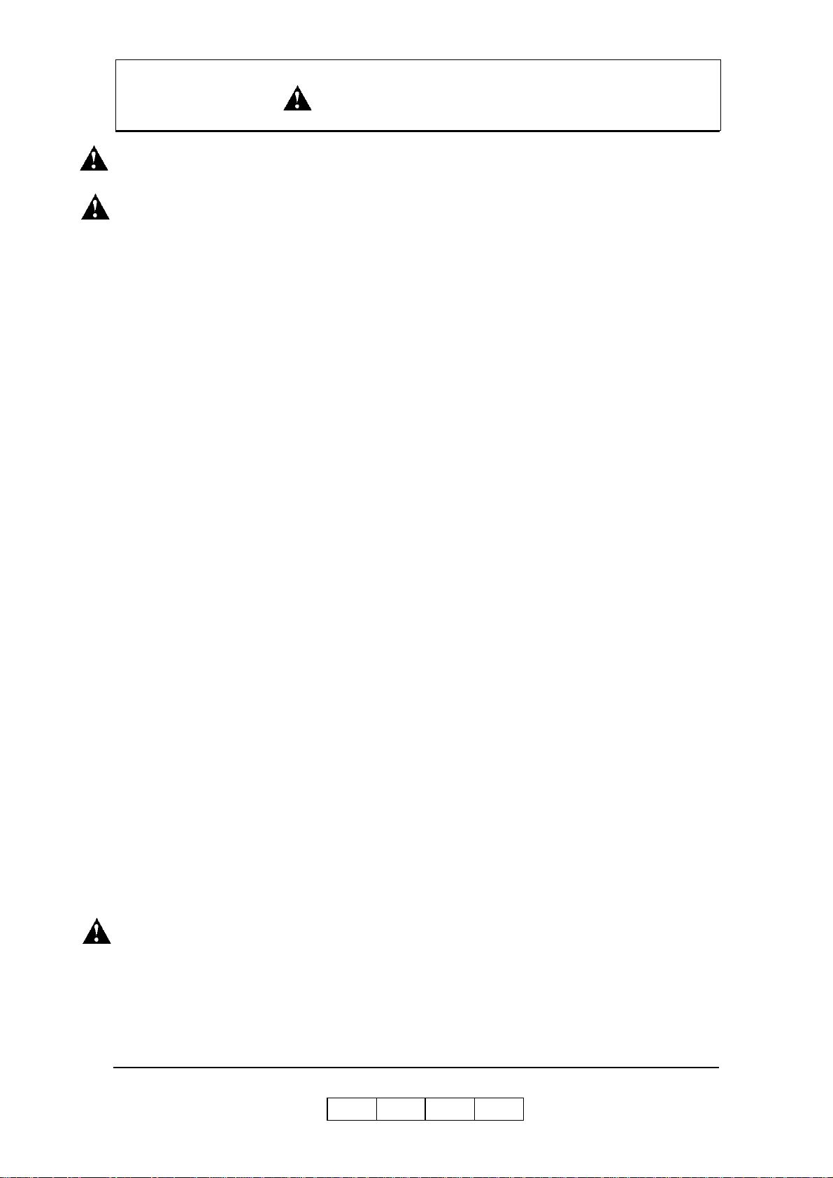
Pay particular attention to Notes, Cautions, and Warnings. These alert you to critical
information, as follows:
NOTE:
Provides important additional information.
CAUTION!
Alerts you to an operating procedur e, practice, or condition that, if not
strictly observed, might result in damage to the equipment.
WARNING!
Alerts you to an operating procedur e, practice, or condition that, if not
strictly observed, can result in safety hazards to personnel, severe injury,
or loss of life.
For More Information
Refer to the following related documents for more details about your printer.
■ Installation Guide
■ Engine Maint enance Manu al
■ Controller Maintenance Manual
■ Parts Catalog
0-2 Introduction
OG L
0 0
Page 29

What This Chapter Provides
This chapter describes the parts and functions of the printer.
■ Printer Features
■ External View of the Printer
■ Internal View of the Printer
■ Powering On the Printer
■ Powering Off the Printer
■ Space Required for Installation
Chapter 1
Printer Overview
OG L
Printer Overview 1-1
0 0
Page 30

Printer Features
The printer is a high-speed, heavy duty laser printer for a 1.5M page/month printing
environment. It incorporates a wide variety of features:
■ High-Speed and High-Quality Printing.
❒ Print speed is up to 156 pages per minute (ppm), A4/Letter/Legal (Simplex).
❒ The printing output is at a reso lut i o n of 60 0 dots per inch (dpi), assuring
razor-sharp graphic and text output, even at very small point sizes.
■ Flexible Paper Source and Delivery.
Paper Source:
❒ Standard – One 2,500-she et and one 1,000-sheet universal paper trays.
❒ Option – High Capacity Feeder with 3,000 to 12,000-sheet capacity.
Paper Delivery:
❒ Standard – Container Stacker with 2,000 to 4,00 0-sheet capacity and st acking
capability.
❒ Option – Additional Container S tacker with 2,000 to 4 ,000-sheet capacity and
stacking capability.
■ Multiple Original Printing (MOP) – for printing of multiple collated document
sets without multiple file transfers. Processes PCL and PostScript jobs once,
stores the images on disk, and prints each set from disk (after the first set).
■ Virtual Printer Technology (VPT) – allows a single printer to offer print services,
or virtual printers, each of which is configured by the Network Administrator.
■ Web Utilities – for remote access to the printer through the Internet or your
company’s Intranet.
■ Ergonomic operati on.
❒ The easy-to-read display clearly shows the operational status of the printer.
1-2 Printer Overview
OG L
0 0
Page 31

■ High-volu me pr i nti ng .
❒ Two standard paper trays with approximately 3,500-sheet capacity total.
❒ Optional High Capacity Feeder (HCF) adds up to 12,000 additional sheets.
❒ Together they allow continuous printing of up to 15,500 sheets.
■ Supports a wide-range of media types (plain, bond, letterhead, special application,
recycled, labels) and sizes. See “Paper” on page 3-2 for more information.
■ Printer Language Support.
❒ PCL5e and PCL XL printer langua g e.
❒ PostScript Level III (Adobe) printer language.
❒ P DF and TIFF files printing.
NOTE:
PDF Files printing is only supported for PDF Version 1.3.
■ Network.
❒ Ethernet 10/100/1000 Base-T with onboard network
❒ Additional Ethernet 10/100 Base-T with Multi-protocol NIC option.
■ Network Protocol.
❒ TCP/IP, LPR/LPD and IPP with onboard network.
❒ TCP/IP, LPR/LPD, NetWare IPX/SPX, Ethertalk with Multi-protocol NIC
option.
■ Easy installation of additional fonts and macros using the PCL Startup File.
I/O Configurations
■ Ethernet 10/100/1000 Base-T with onboard network.
■ Additional Ethernet 10/100Base-T with Multi-protocol NIC option.
Operator Control Panel
The Operator Control Panel (OCP) is your physical interface to the printer's features
and functions. From the control panel, you can monitor the printer's operating status
and configure the specific printer functions.
See Chapter 2 for detailed information about the OCP.
OG L
Printer Overview 1-3
0 0
Page 32

External View of th e Printer
The following illustration shows the printer with optional Container Stacker, optional
High Capacity Feeders, optional Finisher Transfer Unit and optional Attention Light
are installed.
7. High Capacity Feeder 1
10. High Capacity Feeder 2
12. HCF2 Upper Tray
11. HCF2 Lower Tray
3. Toner Supply Cover
9. HCF1 Upper Tray
8. HCF1 Lower Tray
Figure 1-1. External View of the Printer
1. Power Switch
6. Tray 2
4. Operator Control Panel
13. Sample Tray
2. Front Cover
5. Tray 1
21. T r a nsit Pass Unit
20. Attention Light
14. Container Stacker 1
16. Container1 Upper Tray
17. Container Stacker 2
19. Container 2
Upper Tray
15. Container1 Lower Tray
Type 156
18. Container 2
Lower Tray
Table 1-1. External View of the Printer
Key Component Description
1 Power Switch Press to turn the printer on and off.
2 Front Cover Open to replace units, clear paper j ams, or clean the print er.
3 Toner Supply C over Open to replenish the toner supply.
4 Operator Control Panel (OCP) Displays printer status and menu information.
5 Tray 1 Holds up to 2,500 sheets of paper.
6 Tray 2 Holds up to 1,000 sheets of paper.
7 High Capacity Feeder 1 Two 3,000-sheet input trays.
8 HCF1 Lower Tr ay Holds up to 3,000 sheets of paper.
9 HCF1 Upper Tr ay Holds up to 3,000 sh eets of paper.
10 High Capacity Feeder 2 Two 3,000-sheet input trays.
11 HCF2 Lower Tray Holds up to 3,000 sheets of paper.
12 HCF2 Upper Tr ay Holds up to 3,000 sheets of paper.
13 Sample Tray 100-sheet output tray
14 Container Stacker 1 Two 2,000-sheet output trays
15 Container1 Lower Tray Stacks up to 2,000 sheets of paper.
16 Container1 Upper Tray Stacks up to 2,000 sheets of paper.
17 Container Stacker 2 Two 2,000-sheet output trays
18 Container2 Lower Tray Stacks up to 2,000 sheets of paper.
19 Container2 Upper Tray Stacks up to 2,000 sheets of paper.
20 Attention Light Indicates er ror, warning and printer ready status.
21 Transit Pass Unit Type 156 Paper transport unit for Post Device.
1-4 Printer Overview
OG L
0 1
Page 33

Internal View of the Printer
1. Toner Supply Cover
2. Developer Duct
3. Drum Unit
4. Fuser Unit
6. SF Cover
5. Toner Bottle / Toner Bag
7. Main AC Power Switch
Figure 1-2. Internal V iew of the Printer
Table 1-2. Internal View of the Printer
Key Component Description
1 Toner Supply Cover Open this cover when supplying the new toner.
2 Developer Duct
3 Drum Unit OPC drum.
4 Fuser Unit Fuses the toner on the paper.
5 Toner Bottle/Toner Bag Collect the waste toner.
6 SF Cover Open this cover when replacing the Fine Filter.
7 Main AC Power Switch Turn the printer main AC power on and off
Mount the developer bot tle onto th e devel op er du ct to repla ce
consumed developer
OG L
Printer Overview 1-5
0 1
Page 34

Powering On the Printer
The printer has two power switches, the Main AC Power Switch and the Power
Switch. The location of switches are shown below. Both switches are marked “I” for
power on.
Main AC Power Switch
When the printer is powered on, the printer go through a power-up sequence that takes
approximately 5 minutes. During the power-up sequence, the printer runs a series of
internal tests.
CAUTION!
Once the printer is powered off, wait at least 5 seconds to next power on.
If the printer does not power on, power off the printer, wait at least 30
seconds, then power on the printer again.
Power Switch
Figure 1-3. Powering On the Printer
1-6 Printer Overview
OG L
0 0
Page 35

Power ing Off the Prin ter
The printer should only be powered off when it is in a “Ready” state; that is, there are
no jobs printing or proc essing. The following OCP displays indicate nor mal
conditions. In these conditions, wait until printing is complete and the printer is
Ready, then switch off the Power Switch.
Figure 1-4. Normal Conditions
If the printer status is Pause/Offline, touch the “” button to return printer to a Ready
status bef ore pow eri n g off.
Figure 1-5. Pause/Offline
OG L
Printer Overview 1-7
0 0
Page 36

Clearing Error Con di tio ns
OCP Alternates between Ready and Processing
1. Cancel the print job(s). For detail of canceling print job,
Figure 1-6. OCP Alternates between Ready and Processing
E0XX, E1XX Error
1. Correct the error and touch the “” button on the OCP display.
2. Wait until printing is complete and the printer returns to Ready, then switch off
the main power.
1-8 Printer Overview
Figure 1-7. E0XX, E1XX Error
OG L
0 0
Page 37

E2XX, EC#XX Call for Service Error
1. Touch the “” button on the OCP display.
2. Wait until printing is complete and the printer returns to Ready.
Figure 1-8. Call for Service Error
CAUTION!
If the message “Open the Fuser cover , and check that there is no paper” is
displayed on the OCP , open the Fuser cover and check the Fuser unit refer
to Chapter 4.
3. If the Call for Service error persists, cancel the print job(s), power off the printer,
and contact your authorized service technician.
OG L
Printer Overview 1-9
0 1
Page 38

Space Required for Installation
)
Install the printer in a well-ventilated place and keep around the printer as shown
below for safe and effective operation.
Required Sp ace (for Maximum Configuration
1-10 Printer Overview
Figure 1-9. Space Required for Installation
OG L
0 1
(Top View)
Page 39

What This Chapter Provides
This chapter contains information on the following topics.
■ Description of Control Panels
■ OCP Menu Icons and Buttons
■ Using the OCP Menus
■ OCP Menu Struct ure
■ Sub Panel
Chapter 2
Control Panels
OG L
Control Panels 2-1
0 0
Page 40

Description of Control Panels
The Operator Control Panel (OCP) is a touch panel display that you use to set up print
options and monitor job and printer status. It is also used by the Network Administrator
to configure the printer and by the Service Technician to perform maintenance on the
printer.
This prin ter also have sub panel equipped to each In put and Output Trays. S ub panel
has some functions to each Input and Output Trays.
Sub Panel (Input Tray)
Operator Control Panel
Sub Panel
(Output Tra y)
Figure 2-1. Operator Control Panel
2-2 Control Panels
OG L
0 0
Page 41

OCP Menu Icons and Buttons
The menus are accessed via the touch panel. Each OCP menu consists of icons and
buttons that you use to make selections. The icons and buttons are defined below . See
“Main Menu” on page 2-8 for more icons.
Table 2-1. OCP Menu Icons and Buttons
Icon or
Button
?
i
Name Function
Help Touch to display Help on the current screen.
Information From the Main Menu, displays information about the printer and
Pause/Offline Touch to pause the printer.
Resume/Online When the printer is offline, touch to return to Ready status.
Return to Main
Menu
Previous Menu Touch to cancel the current selection and return to the previous screen
More Options Touch to display additional options for the current selection.
Enter or Accept Confirm or Done. Touch to confirm your selection and return to the
consumables.
From relevant scre ens, displ ays an illus tr ation o f the p a per trays
or finisher trays.
Touch to cancel the current selection and return to the Main Menu.
or menu.
previous screen or menu.
Sample Touch to dup lica te a curr ent prin ting page and output to the sample tray.
Clear Button Touch to erase entire entry.
Delete Button Touch to erase last character entered.
–
Ten Key Use to enter numeric values.
Brightness Use to adjust backlight value of the OCP display.
Contrast Use to adjust the contrast level of the OCP display.
Status Bar Displays the current screen name and/or any system messages.
Control Panels 2-3
OG L
0 0
Page 42

Using the OCP Menus
There are 4 types of OCP Menu displays.
■ Option Button
■ Ten Key Pad
■ Change Button (+ / -)
■ Change But t on (E nab l e /D i s abl e )
A brief description of each menu and how to use it follows.
Using the Option Button Menu
The image below is a sample of a menu with Option buttons. The status bar indicates
the current setting. In this sample there is a More Options button indicating there are
more options to choose from on the following page.
Status Bar
Option Buttons
Previous Menu
More Options
Figure 2-2. Option Button Menu
Enter/Accept
To use this menu,
1. Touch the Option button. The selection is highlighted.
2. Touch the Enter/Accept button to activate the selection.
NOTE:
The selection will be ignored if the Enter/Accept button is not touched, or
if any other button is touched prior to touching Enter/Accept.
2-4 Control Panels
OG L
0 0
Page 43

Using the Ten Key Pad Menu
The image below is a sample of a menu with a ten key pad. It is used to enter numeric
values.
Status Bar
Text Box
Ten Key Pad
Figure 2-3. Ten Key Pad Menu
Erase Entire Entry
Erase Last Digit
Unit Value
Previous Menu
Enter/Accept
To enter a value,
1. Touch the appropriate numbers on the pad. The value appears in the T ext Box.
2. Touch the desired Unit Value button (if applicable).
3. Touch the Enter/Accept button to activate the entry.
NOTE:
The entry will be ignored if the Enter/Accept button is not touched, or if
the Previous Menu button is touched prior to touching Enter/Accept.
OG L
Control Panels 2-5
0 0
Page 44

Using the + / - Change Button Menu
The image below is a sample of a menu with a + / - change button. It is used to increase
and decrease the OCP brightness and contrast. The current value is displayed to the
right of the icon.
Decrease -
Increase +
Figure 2-4. + / - Change Button Menu
10
10
Current Value
3
Previous Menu
Enter/Accept
To increase or decrease the value,
1. Touch the + or - to adjust brightness or contrast. The numeric value and the
display will change immediately.
NOTE:
Brightness control is not displayed in the production model after April ‘06.
Touch the Enter/Accept button to activate setting.
NOTE:
The setting will be ignored if the Enter/Accept button is not touched, or if
the Previous Menu button is touched prior to touching Enter/Accept.
2-6 Control Panels
OG L
0 1
Page 45

Using the Enable/Disable Change Button Menu
The image below is a sample of a menu with an Enable/Disable toggle. It is used to turn
an option on or off.
40 seconds
Disabled
Options
Figure 2-5. Enable/Disable Change Button Menu
1. Touch the Option Button to toggle between enable and disable. The current
setting appears to the right.
2. When you are finished, touch the Previous Menu button.
NOTE:
The Enter/Accept button is not used for Enable/Disable options. The
setting is activated immediately.
Disabled
Middle
Current Status
Previous Menu
OG L
Control Panels 2-7
0 2
Page 46

OCP Menu Structure
The OCP menu is structur ed as show n on the fo llowing pages. A top level me nu screen
is shown followed by a description of the options on the screen. A table that outlines
the complete structure of the menu is also provided. Each box in the table represents an
OCP display menu. Use this information to assist you in setting printer options.
Main Menu
The Main Menu screen is shown below. A description of the icons that make up the
screen follows.
Status Bar
Printer Menu
Setup Menu
Jobs Menu
Printer Menu
Touch to display the Printer Menu.
Setup Menu
Touch to display the Setup Menu.
Reports Menu
Touch to display the Reports Menu.
Help
Current Screen
Information
Reports Menu
Sample
Pause/Offline
Figure 2-6. Main Menu
Jobs Menu
Touch to display the Cancel Printing screen and view a list of all jobs.
For other buttons or ic ons, see “Using the Option Button Menu” on page 2-4.
2-8 Control Panels
OG L
0 0
Page 47

Information Menu
When you touch the information icon on the Main Menu this screen is displayed. You
can use it to determine the current settings and status of the options described below.
See Table 2-2 on page 2-10 for the complete Information Menu structure.
Printer
Touch to display information about the engine and controller software revision, error
counts, and the current paper type and source settings.
Consumables
Figure 2-7. Information Menu
Displays the status of the consumables: Toner, Developer Mix., OPC Sheet, and OPC
Sheet Counter.
Usage
Displays current information regarding print density, preventative maintenance, and
page coun ts.
Paper Output
Displays current information regarding the Output Tray of the printer.
Network
Displays information such as MAC and IP Address, Gateway Address, Subnet Mask
and HTTP Port.
OG L
Control Panels 2-9
0 0
Page 48

Table 2-2. Information Menu St ructure
Level 1 Level2 Level 3 Level 4
Informati on Printer 1 Size, Status, Type, Weight
2 Size, Status, T ype, Weight
HCF1 Lower (Note1) Size, Sta tus, Type, Weight
HCF1 Upper (Note1) Size, Status, Type, Weight
HCF2 Lower (Note1) Size, Sta tus, Type, Weight
HCF2 Upper (Note1) Size, Status, Type, Weight
Printer Graphic
Default Paper Source
Error Count of This Period
Controller Revision
Consumable Toner Normal/Low
Developer Mix (current/limit k)
OPC Sheet (current/limit k)
OPC Sheet Counter (curren t/limit k)
Usage Toner Cov erage (current %)
PM Due In (current k)
Total Page Counter (current k)
Process Counter (current k)
Click Charge Counter (current)
Paper Output 1L Paper Size, Bask et Information, Basket Size
1U Paper Size, Basket Information, Basket Size
2L (Note2) Paper Size, Basket Information, Basket Size
2U (Note2) Paper Size, Basket Information, Basket Size
Printer Graphic
Network Network (AUX) MAC Address
IP Address
Subnet Mask
Gateway Address
HTTP Port
Network (NIC) MAC Address
IP Address
Subnet Mask
Gateway Address
HTTP Port
Note 1: This display is only available when the HCF is installed.
Note 2: This display is only available when the additional stacker is installed.
2-10 Control Panels
OG L
0 2
Page 49

Printer Menu
When you select Printer icon from the Main Menu, this screen is displayed. You use
the Printer Menu to gain access to the printing options described below. See Table 2-3
beginnin g on pa ge 2-16 for the complete Printer Menu structure.
Paper Source
■ Default
Defines th e defa ult paper tr ay. Use this w hen th e pape r sour ce is n ot de signat ed by
a host command. If a command from the host defines the paper source, the OCP
setting is ignored. Also if the paper source is specified in the Virtual Printer of the
Web, the OCP setting is ignored.
Figure 2-8. Printer Menu
■ Paper Size
When Paper Size is selected the paper size of the currently selected paper source
is displayed. When the “Custom Size Switch” in the tray is set to “Standard”,
paper size is automatically detected.
T o use the OCP to set the paper size to something other than the standard sizes, set
the Custom Size Switch in the tray to “Custom”, then select Paper Size on the
OCP. See “Paper Sizes, Paper Weights, Paper Types and Paper Color” on page 3-
3 for more information.
■ Paper Type
Defines the paper type to desired input tray. The paper type screen displays
currently selected paper type, and press the option buttons to change to desired
paper type. See “Paper Sizes, Paper Weights, Paper Types and Paper Color” on
page 3-3 for more information.
■ Paper Color
Defines the paper color to desired input tray. The paper color screen displays
currently selected paper color, and press the option buttons to change to desired
paper color. See “Paper Sizes, Paper Weights, Paper Types and Paper Color” on
page 3-3 for more information.
OG L
Control Panels 2-11
0 2
Page 50

■ Paper Weight
Defines the paper weight to desired input tray. The paper weight screen displays
currentl y defined paper weight, and redefine to desired pa per weight by this
screen. See “Paper Sizes, Paper Weights, Paper Types and Paper Color” on
page 3-3 for more information.
■ HV Adjust
The print position can be adjusted vertically and horizontally using the HV Adjust
option. The white arrow on the HV Adjust screen indicates paper feed direction.
The adjustment can be set to millimeters or inches and the range is -6.3 to +6.3
millimeters (-0.25 to +0.25 inches) in increments of 0.1 millimeter (0.01 inch).
Difference positions can be set for front and back side in duplex printing mode.
See “Setting the HV Adjust Values” on page 3-22 for more information.
■ Table Adjust
Defines the table height setting of the each input tray. This option can be adjusted
to five settings: +2, +1, Normal, -1 or -2. See “Setting the Table Adjust” on
page 3-24 for more inf orm ation .
■ Paper Moisture
Defines the Paper Moisture setting to each input tray. This option can be adjusted
to four settings: Highest, Higher, Normal and Lower. See “Setting the Paper
Moisture” on page 3-26 for more information.
■ HCF Tray Control
Defines the HCF tray control mode if the optional HCF is installed. This option
can be set to the “Normal Pick Mode” or the “Prior Pick Mode”.
❒ Normal Pick Mode
The printer feeds a paper from t he HCF tray aft er las t pape r is fed from t he
standard tray (Tray 1/2) when the tray is switched from the standard tray to
the HCF tray .
In this mode, there is an interval between last paper fed from the standard tray
and first paper fed from the HCF tray.
❒ Prior Pick Mode
When the tray is switched from the standard tray to the HCF tray, the printer
starts to feed a paper from the HCF tray before feeding a paper from the
standard tray if the data processing of the paper fed from the HCF has
completed.
The paper fed from the HCF tray stops at the HCF exit, and is fed
continuously after last paper fed from the standard tray.
The tray switching time at Prior Pick Mode is shorter than Normal Pick Mode.
However more papers may be wasted than Normal Pick Mode when paper
jam or an error occurred.
Also there are some limitations when using this mode. See “Printer Notice”
on page 5-7 for detail.
2-12 Control Panels
OG L
0 2
Page 51

Paper Output
■ Default Output
■ Stacking Level
Use this when the output tray is not designated by a host command. If a command
from the host defines the output tray, the OCP setting is ignored.
Defines the Upper limit of the stacking level of each output tray. This option can
be adjusted to three settings: 50%, 75% or 100%.
OG L
Control Panels 2-13
0 1
Page 52

Options
■ Wait Timeout
Defines the waiting period (in seconds) from reception of last data to the
reception of next data. If data is not received within the defined period, the job is
cancelled. A command from the host will override the OCP setting.
■ LPD Queuing
Can be set to enable or disable. When set to disable, printer does not accept next
job via LPR/LPD protocol until current job process is completed.
■ Duplex Always
Can be set to enable or disable. When set to enable, the printer will always prints
the job by duplex mode .
■ Print Density
Print Density can be adjusted to five settings: Light, Semi-Light, Middle, SemiDark or Dark.
■ Auto Proof Sample
This function provides the automatic proof sample printing instead of manually
pressing the “Sample” button on the OCP . Print interval of the sample page can be
set from 0 to 5,000 e very 500 sheet (0, 500, 1,000, 1,500, ... 5,000). For example,
If interval is set to “500”, then printer automatically duplicates the proof sample
to the Sample Tray every 500 sheet during printing. If the interval is set to “0”,
this function is disabled.
PostScript
■ Cover Insert Mode
Defines the mode of the Cover Inserter when it is installed. Set to “Cover Insert”
when Cover Inserter is used. Set to “Bypass” when Cover Inserter is not used.
■ Print Errors
Can be set to enable or disable. When set to enable, the printer will prints error
page when PostScript error is occurred.
■ Best Fit
Can be set to enable or disable. When set to en able, the printer will prints the p age
image to fit the paper size.
■ Job Timeout
Defines the time limit (in seconds) for processing of the PostScript job.
■ Halftone Density
Halftone Density can be adjusted to three settings: Light, Medium or Dark..
NOTE:
The Halftone Density menu is only displayed when the Halftone Selection
in the Service menu is enabled.
2-14 Control Panels
OG L
0 4
Page 53

Test Print
PCL
Use this button to prints the test pattern for checking the print quality or the print
position. Following test patterns are available in this menu.
■ Cross Pattern
This option prints the combination of Horizontal/Vertical/Diagonal lines for
checking the print position. This pattern is printed by duplex.
■ Raster Pattern
This option prints th e 8 page of the raster patte rn and 8 page o f the blank pages
(total 16 pages) for checking the print quality. This pattern is printed by simplex.
■ Wide A4
Can be set to enable or disable. When set to enable, the printer changes the
margin/printable area of A4 paper so that 80 10-pitch characters may be printed
on a line.
■ Requested Tray
Defines the printer behavior when requested tray is specified in jobs.
❒ Exclusively
Printer should print from the requested tray only.
❒ First
Printer should print from the requested tray first.
OG L
Control Panels 2-15
0 1
Page 54

Table 2-3. Printer Menu Structure
Level 1 Level 2 Level 3 Level 4 Leve l 5 Level 6
Printer Paper Source Default
(Note 1)
Paper Size
(Note 1)
Paper Type
(Note 1)
Auto Select
1
2
HCF1 Lower
(Note2)
HCF1 Upper
(Note2)
HCF2 Lower
(Note2)
HCF2 Upper
(Note2)
1
2
HCF1 Lower
(Note2)
HCF1 Upper
(Note2)
HCF2 Lower
(Note2)
HCF2 Upper
(Note2)
1
2
HCF1 Lower
(Note2)
HCF1 Upper
(Note2)
HCF2 Lower
(Note2)
HCF2 Upper
(Note2)
Folio SEF, Folio LEF, Super B SEF,
Executive LEF, Letter SEF, A4 SEF,
Legal SEF, Custom Size (Note 3)
Folio SEF, Folio LEF, Super B SEF,
Executive LEF, Letter SEF, A4 SEF,
Legal SEF, Custom Size (Note 3)
Folio SEF, Folio LEF, Super B SEF,
Executive LEF, Letter SEF, A4 SEF,
Legal SEF, Custom Size (Note 3)
Folio SEF, Folio LEF, Super B SEF,
Executive LEF, Letter SEF, A4 SEF,
Legal SEF, Custom Size (Note 3)
Folio SEF, Folio LEF, Super B SEF,
Executive LEF, Letter SEF, A4 SEF,
Legal SEF, Custom Size (Note 3)
Folio SEF, Folio LEF, Super B SEF,
Executive LEF, Letter SEF, A4 SEF,
Legal SEF, Custom Size (Note 3)
Plain, Bond, Color, Label, Letterhead,
Preprinted, Prepunched, Recycled,
Tracing Paper, Special, Other
Plain, Bond, Color, Label, Letterhead,
Preprinted, Prepunched, Recycled,
Tracing Paper, Special, Other
Plain, Bond, Color, Label, Letterhead,
Preprinted, Prepunched, Recycled,
Tracing Paper, Special, Other
Plain, Bond, Color, Label, Letterhead,
Preprinted, Prepunched, Recycled,
Tracing Paper, Special, Other
Plain, Bond, Color, Label, Letterhead,
Preprinted, Prepunched, Recycled,
Tracing Paper, Special, Other
Plain, Bond, Color, Label, Letterhead,
Preprinted, Prepunched, Recycled,
Tracing Paper, Special, Other
Length: 7-18”
(178-457.2mm)
Width: 8-14”
(203-355.6mm)
Length: 7-18”
(178-457.2mm)
Width: 8-14”
(203-355.6mm)
Length: 7-18”
(178-457.2mm)
Width: 8-14”
(203-355.6mm)
Length: 7-18”
(178-457.2mm)
Width: 8-14”
(203-355.6mm)
Length: 7-18”
(178-457.2mm)
Width: 8-14”
(203-355.6mm)
Length: 7-18”
(178-457.2mm)
Width: 8-14”
(203-355.6mm)
Note 1: Commands from the Host override OCP settings.
Note 2: This menu is displayed only when the HCF is installed.
Note 3: This menu is available only when the Custom Size Switch in is set to “Custom”.
2-16 Control Panels
OG L
0 4
Page 55

Table 2-3. Printer Menu Structure - Continued
Level 1 Level 2 Level 3 Level 4 Level 5 Level 6
Printer Paper Source Paper Color
(Note 1)
Paper
Weight
(Note 1)
HV Adjust
Table Adjust
1 White, Pink, Yellow,
2 White, Pink, Yellow,
HCF1 Lower
(Note 2)
HCF1 Upper
(Note 2)
HCF2 Lower
(Note 2)
HCF2 Upper
(Note 2)
1 60-199gm
2 60-199gm
HCF1 Lower
(Note 2)
HCF1 Upper
(Note 2)
HCF2 Lower
(Note 2)
HCF2 Upper
(Note 2)
Front H/V Direction -0.25” to +0.25”
Back H/V Direction -0.25” to +0.25”
1:Thick +2/+1/Normal/-1/-2
1:Thin +2/+1/Normal/-1/-2
2:Thick +2/+1/Normal/-1/-2
2:Thin +2/+1/Normal/-1/-2
HCF1L:Thick
(Note 2)
HCF1L:Thin
(Note 2)
HCF1U:Thick
(Note 2)
HCF1U:Thin
(Note 2)
HCF2L:Thick
(Note 2)
HCF2L:Thin
(Note 2)
HCF2U:Thick
(Note 2)
HCF2U:Thin
(Note 2)
Buff, Goldenrod, Blue,
Green, Custom
Buff, Goldenrod, Blue,
Green, Custom
White, Pink, Yellow,
Buff, Goldenrod, Blue,
Green, Custom
White, Pink, Yellow,
Buff, Goldenrod, Blue,
Green, Custom
White, Pink, Yellow,
Buff, Goldenrod, Blue,
Green, Custom
White, Pink, Yellow,
Buff, Goldenrod, Blue,
Green, Custom
(33-11 0 lb. index,
16-53 lb. bond)
(33-11 0 lb. index,
16-53 lb. bond)
60-199gm
(33-11 0 lb. index,
16-53 lb. bond)
60-199gm
(33-11 0 lb. index,
16-53 lb. bond)
60-199gm
(33-11 0 lb. index,
16-53 lb. bond)
60-199gm
(33-11 0 lb. index,
16-53 lb. bond)
+2/+1/Normal/-1/-2
+2/+1/Normal/-1/-2
+2/+1/Normal/-1/-2
+2/+1/Normal/-1/-2
+2/+1/Normal/-1/-2
+2/+1/Normal/-1/-2
+2/+1/Normal/-1/-2
+2/+1/Normal/-1/-2
2
2
2
2
2
2
Color 1, Color 2, Color 3, .....
Color 79, Color 80
Color 1, Color 2, Color 3, .....
Color 79, Color 80
Color 1, Color 2, Color 3, .....
Color 79, Color 80
Color 1, Color 2, Color 3, .....
Color 79, Color 80
Color 1, Color 2, Color 3, .....
Color 79, Color 80
Color 1, Color 2, Color 3, .....
Color 79, Color 80
(-6.3 to +6.3mm)
(-6.3 to +6.3mm)
Note 1: Commands from the Host override OCP settings.
Note 2: This menu is displayed only when the HCF is installed.
OG L
0 3
Control Panels 2-17
Page 56

Table 2-3. Printer Menu Structure - Continued
Level 1 Level 2 Level 3 Level 4 L evel 5 Level 6
Printer Paper Source Paper Moisture 1 Highest/Higher/
2 Highest/Higher/
HCF1 Lower
(Note 2)
HCF1 Upper
(Note 2)
HCF2 Lower
(Note 2)
HCF2 Upper
HCF Tray Control
(Note 2)
Paper Output Default Output
Options Wait Timeout 0-999 second s
PostScript Print Errors Enable/Disable
Test Print Cross Pattern Select Paper Source Select Paper
PCL Wide A4 Enable/ D isable
(Note 1)
Stacking Level 1 Lower :Short 100%/75%/50%
LPD Queuing Enable/Disable
Duplex-Always Enable/Disable
Print Density Light/Semi-Light/
Auto Proof
Sample
Cover Inse r t
Mode (Note 4)
Best Fit Ena ble/Disable
Job Timeout 0 second or
Halftone Density
(Note 3)
Raster Pattern Select Paper Source Select Paper
Requested Tray Exclusively/First
(Note 2)
Normal Pick Mode
Prior Pick Mode
Container 1 Lower
Container 1 Upper
Container 2 Lower
(Note 1)
Container 2 Upper
(Note 1)
Pass Through (Note 4)
Finishing (Note 4)
1 Lower :L ong 100%/75%/50%
1 Upper :Short 100%/75%/50%
1 Upper :L ong 100%/75%/50%
2 Lower :Short
(Note 1)
2 Lower :Long
(Note 1)
2 Upper :Short
(Note 1)
2 Upper :L ong
(Note 1)
Middle/Semi-Dark/
Dark
0, 500, 1,000, 1,50 0,
2,000, 2,500, 3,000,
3,500, 4,000, 4,500,
5,000
Cover Insert/Bypass
15-999 se conds
Light/Medium/Dark
Normal/Lower
Normal/Lower
Highest/Higher/
Normal/Lower
Highest/Higher/
Normal/Lower
Highest/Higher/
Normal/Lower
Highest/Higher/
Normal/Lower
100%/75%/50%
100%/75%/50%
100%/75%/50%
100%/75%/50%
Destination
Destination
Note 1: This menu is displayed only when the Additional Stacker is installed.
Note 2: This menu is displayed only when the HCF is installed.
Note 3: This menu is displayed only when the Halftone Selection in the Service menu is
enabled.
Note 4: This menu is available only when the Transit Pass Unit Type 156 is installed.
2-18 Control Panels
OG L
0 3
Page 57

Setup Menu
When you select Setup icon from the Main Menu, this screen is displayed. Use it to gain
access to the Setup option screens that are described below. See Table 2-4 on page 2-
23 for the complete Setup Menu structure.
OCP
■ Brightness
Figure 2-9. Setup Menu
Brightness of the OCP can be adjusted. The range is 1 to 16. The factory default is
10.
Service
NOTE:
This option is not displayed in the production model after April ‘06.
■ Contrast
Contrast of the OCP can be adjusted. The range is 1 to 16. The factory default is
10.
■ Buzzer Volume
Buzzer Volume of the OCP can be adjusted. The range is 1 to 5. The factory
default is 3.
The Service option is password protected and this option is used by Authorized Service
Technician only.
OG L
Control Panels 2-19
0 2
Page 58

System
The System option is password protected. Contact your System Administrator if you
need access to these options.
■ Software Log
Create software log
■ Network
Defines the parameters of the network. The standard network (10/100/1000B-T)
is displayed as “Network (AUX)”. If the Multi-protocol NIC option (10/100B-T)
is installed, “Network (NIC)” is also displayed. Following parameters can be set
to each networks.
❒ IP Address
Can be set desired IP Address. Factory default is 192.0.0.1.
❒ Subnet Mask
Can be set desi red Subnet Mask. Factory default is 0.0. 0.0.
❒ Gateway Address
Can be set desired Gateway Address. Factory default is 0.0.0.0.
❒ Boot Method
Can be set Boot Method to Static or DHCP. If the Multi-protocol NIC option
is installed, can be set to Auto Select, DHCP, RARP or Static. Factory default
is STATIC.
❒ HTTP Port
Can be set HTTP port to desired port number. Factory default is 80.
■ Exit Jam Recovery
Can be set to enable or disable. When set to enable, the printer will reprint pages
that were improperly printed due to a paper jam.
■ Calendar
The following settings can be made.
❒ Time Zone - See the following table for options.
❒ Date - 0000/00/00 (Year/Month/Day)
❒ Time - Set printer clock
■ Country Co de
Select the appropriate country code used in international phone numbers. The
default setting is 1.
■ Energy Save Mode
Can be set to enable or disable.
2-20 Control Panels
OG L
0 3
Page 59

■ Energy Save Time
Defines the waiting time (in minutes) to enter the Energy Save Mode when
Energy Save Mode i s enabled.
■ Password
Use to change the System password. The system password is used by your System
Administrator and provides access to the system parameters.
■ Auto Online
Can be set to enable or disable. When set to enable, printer automatically return
from offline to online about 7 minutes elapsed after last OCP operation in offline
state. When set to disable, printer never return to online until the “resume/online”
button is pressed.
■ Public R/W
Enable allows read/write when SNMP community name is Public.
■ Auto Backup Time
Defines start time (o’clock) of auto backup. V alid value is 0 - 23.
■ Output Cascade
❒ Cascade Priority
Defines a switching priority of container stacker when auto cascading.
❒ Cascade on CS Open
Defines the behavior when the open switch of container stacker is pressed
during auto cascading. When set to “Stop”, printer stops printing. When set to
“Continue”, printer switches the stacker and continue to print.
OG L
Control Panels 2-21
0 3
Page 60

Consumables
Touch to display the user co nsumable op tions, which i nclude repla cing the developer
mix, OPC Sheet and fuser web.
■ Developer Mix
■ OPC
■ Fuser Web
Select exhaust to empty old developer mix, then select Supply to replenish with
new developer mix. The counter is automatically reset.
❒ OPC Sheet
Select the Winding OPC Sheet to wind the OPC Sheet.
❒ Counter
Select the Counter to reset the winding count when replacing the OPC Sheet.
NOTE:
The OPC menu is only displayed when the OPC Mode in the Service menu
is enabled.
Touch to reset the OCP message when replacing the Fuser Web.
Language
Touch to list the OCP display language options. (English, Deutsch, Français)
Attention Buzzer
Enable or disable the buzzer of the Attention Light if this option is installed.
■ Buzzer: Yellow
Enable or disable the buzzer when the Yellow light is blinking.
■ Buzzer: Red
Enable or disable the buzzer when the Red light is blinking.
2-22 Control Panels
OG L
0 3
Page 61

Table 2-4. Setup Menu Structure
Level 1 Level 2 Level 3 Level 4 Level 5 Level 6 Level 7
Setup OCP Brightness
Service
(Note 1)
System Input Password
Consumable Developer Mix Exhaust
Language English
Attentio n Buzzer
(Note7)
(Note 8)
Contrast 1-16
Buzzer Vol ume 1-5
(Note 2)
OPC
(Note5)
Fuser Web
Deutsch
Français
Buzzer:Yellow Enable/Disable
Buzzer:Red Enable/Disable
1-16
Software Log
Network Network (AUX) IP Address
Network (NI C )
(Note 6)
Exit Jam Recovery Enable/Disable
Calendar Time Zo ne GMT -12:00 to
Date (Note 3)
Country Code
Energy Save Mode Enable/Disable
Energy Save time
(Note 4)
Password Input Password
Auto Onli ne Enable/Di sable
Public R/W Enable/Disable
Auto Backup Time 0-23 o’clock
Output Cascade Cascade Priority Lower to Upper /
Supply
Winding OPC Sheet
Counter
Time
15-230 minutes
Cascade on CS
Open
Subnet Mask
Gateway Address
Boot Method Static
HTTP Port
IP Address
Subnet Mask
Gateway Address
Boot Method Auto
HTTP Port
GMT +12:00
Upper to Lower
Stop / Continue
DHCP
Select
DHCP
RARP
STATIC
Note 1: Use of the service menu i s password protect ed. Contact your authorized Service
Technician.
Note 2: Use of the system menu is password protected. Contact your System Administ rator.
Note 3: Date format is 0000/00/00 (Y ear/Month/Day)
Note 4: Only displayed when Energy Save Mode is enabled.
Note 5: Only displayed when OPC Mode in the Service menu is enabled.
Note 6: Only displayed when Multi-protocol NIC option is installed.
Note 7: Only worked when the Attention Lamp Option is installed.
Note 8: This option is not displayed in the production model after April ‘06.
Control Panels 2-23
OG L
0 3
Page 62

Reports Menu
When you sele ct Reports ico n from the Main Me nu, this screen is displayed. You use
it to print the reports described below.
Status
T ouc h to prin t a st atus r eport a nd ret urn t o the Main Me nu. Th e stat us repo rt show s the
current configuration of the printer and printer usage information.
Demo
Figure 2-10. Reports Menu
T ou ch t o pri nt a dem o r ep ort an d re tur n to the M ain Me nu. The demo re po rt show s the
printer specifications such as speed, paper handling, resolution, etc.
Summary
Touch to print a summary report and return to the Main Menu. The summary report
shows processor, connectivity, RAM and other miscellaneous information.
Disk Directory
Touch to print a disk directory report and return to the Main Menu.
Fonts
Touch to print the font lists of the printer.
Configuration
Touch to print the list of various configuration parameters.
Table 2-5. Reports Menu
Level 1 Level 2 Level3
Reports Status
Demo
Summary
Disk Directory
Fonts PCL Fonts
PostScript Fonts
Configuration
2-24 Control Panels
OG L
0 2
Page 63

Jobs Menu
When you select Jobs icon from the Main Menu, this screen is displayed. You use the
Jobs Menu to canceling print jobs in the printer.
List of Jobs
List of Jobs
Received jobs in the printer are listed in the screen. Contents of the list is shown below.
Job-01 1/3 - 12 ““ 16:02 P
Job-02 0/1-1
Text-fil 0/1-1
Figure 2-11. Jobs Men u
““ 16:03 P
““ 16:08 P
Scroll Bar
Scroll Bar
Select All
Clear All
Delete
““ 16:02 P
User Name
Job Name
Job-01
Current Copy
Total Copy
Page Count
1/3-12
You can touch to select each job for canceling.
Touch to scroll the list of jobs.
Touch to select all print jobs for canceling all print jobs.
Touch to clear all selected jobs to unselect.
Job Status
P: Pause A: Active
C: Cancel
Time
Touch to delete the selected Job(s).
OG L
Control Panels 2-25
0 2
Page 64

Sub Panel
Sub panel is equipped to each Input and Output Tray. The contents of sub panel are
shown below.
Paper Level Indicator
Paper Size LED
Indicates paper size that is loaded in the Input Tray or stacked in the Output Tray. See
“Paper Size Indication” on page 3-4 for indication of each paper size.
Paper Size LED
Select LED
(LED 1)
(LED 2)
(LED 3)
Lock LED
Down Switch
Figure 2-12. Sub Panel
Select LED
When this LED is ON, it means the Tray is currently selected.
When this LED is blinking, it means the following cases;
■ Paper jam is occurred at selected tray.
■ Down Switch was pressed.
Paper Level Indicator (LED1/2/3)
For Input Tray, it indicates paper level (paper amount) that is loaded in the Input Tray
by 3 levels. For Output Tray, it indicates paper level (paper amount) that is stacked in
the Output Tray by 3 levels.
When all LEDs are off, it means the Input Tray or the Output Tray is empty.
When LED3 is blinking, it means the Input Tray or the Output Tray is near empty.
When LEDs for Output Tray are blinking, it means the Output Tray is full.
Lock LED
When this LED is ON, Input Tray or Output Tray is locked, and cannot be opened.
When this LED is OFF, Input Tray or Output Tr ay is unlocked, and can be opened.
When this LED is blinking, it means the table in the Tray is moving up or down.
Down Switch
Use to unlock the Tray . When the Lock LED is ON, press this switch to down the table
in the Tray and unlock the Tray.
2-26 Control Panels
OG L
0 2
Page 65

What This Chapter Provides
This chapter contains information on the following topics.
■ Paper
■ Paper Sizes, Paper Weights, Paper Types and Paper Color
■ Loading Pape r
■ Setting the Non-Standard Paper Size
■ Setting the Paper Weight Value
■ Setting the HV Adjust Values
■ Setting the T a ble Adjust
■ Setting the Paper Moisture
■ Preparing the Stacker
Chapter 3
Paper Handling
■ Removin g Pa per
OG L
Paper Handling 3-1
0 1
Page 66

Paper
T o obtain good print quality, u se the recommended paper and properly position it in the
correct trays. For the loading paper, see “Loading Paper” on page 3-7. Refer to
Appendix B for detailed information about paper specifications and printing on special
print media.
Unacceptable Paper
Avoid using the following media as they cause paper jams and print quality problems.
■ Excessively thick or thin paper
■ Paper that has already been printed (preprinted letterhead is allowed)
■ Wr inkled, torn, or bent paper
■ Moist or wet paper
■ Curled pap er
■ Paper with an electrostatic charge
■ Glued paper
■ Paper with special coating
■ Colored paper with surface treatment
■ Paper una ble to withsta nd temperatur e of 210°C (410°F) and pres sure of about
250kPa (36.3k lbs/in2)
■ Thermal paper
■ Carbon paper
■ Paper with paper fasteners, ribbons, tape, etc., attached
■ Heavily textured paper
■ Label stock with exposed backing sheets
Storing Paper
Store the paper properly to avoid print quality problems and paper jams.
■ Store paper horizontally, in a flat, dry location to avoid wrinkling, bending,
curling, etc.
■ Store paper away from direct sunlight.
■ Store any unused paper in its original packing.
3-2 Paper Handling
OG L
0 0
Page 67

Paper Sizes, Paper Weights, Paper Types and Paper Color
Paper Size
The following table show which paper sizes can be used in this printer. The paper size
is shown in both millimeters and inches.
■ The term SEF indicates the paper is being fed into the printer short edge first and
the term LEF indicates the paper is being fed into the printer long edge first.
■ This printer classifies paper size into “Standard” and “Custom” by using “Custom
Size Switch” in the each tray.
❒ When y ou use “Stan dard” size shown in following table, set the “Custom Size
Switch” in the tray to “Standard”. Printer will automatically detects paper
size.
❒ When you use other than “Standard” size shown in following table, set the
“Custom Size Switch” in the tray to “Custom”, and set appropriate paper size
by using OCP.
See “Loading Paper” on page 3-7 for more information.
Table 3-1. Paper Size
Paper Size
B5 (LEF) 257.0/10.13 182.0/7.17
A4 (SEF) 210.0/8.3 297.0/11.7
A4 (LEF) 297.0/11.7 210.0/8.3
B4 (SEF) 257.0/10.1 364.0/14.3
A3 (SEF) 297.0/11.7 420.0/16.5
Letter (LEF) 279.0/11.0 216.0/8.5
Letter (SEF) 216.0/8.5 279.0/11.0
Folio (LEF) 330.0/13.0 216.0/8.5
Folio (SEF) 216.0/8.5 330.0/13.0
Legal (LEF) 356.0/14.0 216.0/8.5
Legal (SEF) 216.0/8.5 356.0/14.0
Ledger (SEF) 279.0/11.0 432.0/17.0
Executive (LEF) 266.7/10.5 184.2/7.25
Super B (SEF) 305.0/12.0 457.0/18.0
Custom
(0.1 mm/0.1 in. increments)
Leading Edge
mm/inch
203.2 to 355.6/
8.0 to 14.0
Side Edge
mm/inch
177.8 to 457.2/
7.0 to 18.0 (Note1)
Standard
¸
¸
¸
¸
¸
¸
¸
Note 1: Applicable paper size of the HCF1 and HCF2 is from 182.0mm (7.17”) to
457.2mm (18.0”).
Paper Handling 3-3
OG L
0 4
Page 68

Paper Size Indication
Each Input Tray and Output Tray is equipped with the Paper Size LED for indicating
current loaded or stacked paper size in the tray.
Following table shows paper size indication for each paper size.
Paper Size Switch Position Indication
B5 (LEF)
A4 (LEF)
B4 (SEF)
Table 3-2. Paper Size Indication
A3 (SEF)
Letter (LEF)
Legal (LEF)
Ledger (SEF)
Other Sizes Custom
Standard
3-4 Paper Handling
OG L
0 0
Page 69

Paper Weights
The printer can define the following paper weights in all paper trays, including the
HCF.
Paper Size and Feed Orientation Paper Weights
B5(LEF), A4(LEF), Letter(LEF), Legal(LEF),
Executive(LEF), Folio(LEF) and
Custom Size: Side edge =< 215.9mm (8.5”)
A4(SEF), B4(SEF), A3(SEF), Letter(SEF),
Legal(SEF), Ledger(SEF), Super B(SEF),
Folio(SEF) and
Custom Size: Side edge > 215.9mm (8.5”)
To set the paper weight using the OCP, see “Setting the Paper Weight Value” on page
3-19.
Paper Type
The printer can define the following paper type in all paper trays, including the HCF.
■ Plain
■ Bond
From 60g/m2 (16lbs) to 199g/m2 (110(index)lbs)
From 75g/m2 (20lbs) to 199g/m2 (110(index)lbs)
■ Color
■ Label
■ Letterhead
■ Preprinted
■ Prepunched
■ Recycled
■ Tracing Paper
■ Special
■ Other
OG L
Paper Handling 3-5
0 2
Page 70

Paper Color
The printer can define the following paper color in all paper trays, including the HCF.
■ White
■ Pink
■ Yellow
■ Buff
■ Goldenrod
■ Blue
■ Green
Additionally, user can define desired color name as the custom color . The custom color
can be defi ned up to 80 co l o rs.
3-6 Paper Handling
OG L
0 3
Page 71

Loading Paper
Load paper into the trays according to the instructions that follow. Thoroughly
understand and follow the instructions to prevent any paper troubles su ch as paper jams
and paper sk ew. See “Loa ding Speci al Media” on page 3-13 for directions on loading
prepunched and preprinted paper. Paper can be loaded while a print job is running,
except into the tray that is currently in use.
Proper Paper Handlin g
Paper is easily affected by storage conditions and environments much as room
temperature or humidity . When the proper mois ture content of paper is n ot maintained
due to sudden temperature changes, the paper may be deformed as shown below and
cause paper jams.
Curl
Waving
Follow the instructions below to prevent paper jams.
■ Unwrap paper just before printing. Do not leave unwrapped paper for a long time
before printing.
■ Check the paper in the Input Tray has not become deformed before printing. If the
paper is deformed, remove it from the Input Tray.
■ Paper may become deformed and the edges curl upward during the night or
holidays, when the air conditioner or ventilators are temporarily turned off.
Remove paper from the Input Tray and store with moisture-proof wrapping before
the night or holidays.
Checking paper quality
Carefully checking paper quality when unwrapping or before loading into the Input
Tray. Remove and do not use any paper with the following defects.
(When finding any defects immed iately after unwrapping, consult t o the vendor for
paper quality.)
Figure 3-1. Proper Paper Handling (1)
OG L
Paper Handling 3-7
0 2
Page 72

■ Tears, Creases, Dog-eared corners
Paper jams or pape r sk e w ma y be c aus ed in the Input Tray.
Dog-eared corner
Crease
Figure 3-2. Proper Paper Handling (2)
■ Curled edges
The Dram Wrap jam may be caused.
Curled Edge
Tear
Figure 3-3. Proper Paper Handling (3)
■ Burrs
The Dram Wrap jam may be caused.
Burr
Figure 3-4. Proper Paper Handling (4)
When paper jam is occurred, turn the paper in the Input Tray upside down. It may
prevent frequently paper jams caused by this defect.
3-8 Paper Handling
OG L
0 2
Page 73

Loading Paper in Tray
1. Unlock the Tray by pressing the Down Switch if the Lock LED is ON.
Lock LED
Down Switch
Figure 3-5. Loading Paper in Tray (1)
NOTE:
Tray is locked when paper is remaining in the tray. If you press the Down
Switch, wait until the Lock LED is OFF.
2. Open the Tray by pulling it by the handle.
Figure 3-6. Loading Paper in Tray (2)
OG L
0 2
Paper Handling 3-9
Page 74

3. Unpack the paper, and hold the paper on your hand.
Figure 3-7. Loading Paper in Tray (3)
NOTE:
Do not hold t oo much paper at a time. Pick up only 200 - 500 she et at a
time.
4. Place the paper into the Tray.
NOTE:
Gently pla ce the paper on to p. To prevent any dam age to the paper edge,
do not slide the paper on the table.
Place the paper to fit the Front-Left corner in the Input Tray.
Before loading the paper, the tray table position is high, and the paper is
placed more than 1,000 sheets, the tray table is automatically down. The
tray table can be downed manually by pressing the Down Switch.
3-10 Paper Handling
Figure 3-8. Loading Paper in Tray (4)
OG L
0 2
Page 75

5. Move the Paper Guide and contact it to the paper edge.
Paper Guide
Custom Size Switch
Figure 3-9. Loading Paper in Tray (5)
NOTE:
Confirm that there is no large gap between the paper and the Paper
Guide. A paper jam may be caused if there is large gap (more than 1mm).
6. Paper can be added until the Max. Level Indicator
Figure 3-10. Loading Paper in Tray (6)
NOTE:
Do not add the paper more than the max. level indication.
Max. Level Indicator
OG L
Paper Handling 3-11
0 2
Page 76

7. If the paper size you have loaded is a standard size, set the Custom Size Switch to
“Standard” position. If the paper size you have loaded is a non-standard or a
custom size, set the Custom Size Switch to “Custom” position.
Figure 3-11. Loading Paper in Tray (7)
NOTE:
Standard paper sizes are shown in a table “Paper Si zes, Paper Weights,
Paper Types and Paper Color ” on page 3-3.
8. Gently close the Tray.
NOTE:
The Paper Height Error (E0BB, E0BD, E0BF, E0C1, E0C3 or E0C5)
might be caused if there is paper deformation such as curl, waving or
folding. In this case, remove the deformed paper from the Tray.
9. If the paper specification you have loaded is a first use, or paper specification is
changed from previous one, set the paper weight refer to “Setting the Paper
Weight Value” on pa ge 3-19.
10. If the paper size you have loaded is a non-standard size, see “Setting the Non-
Standard Paper Si ze” on page 3-15.
3-12 Paper Handling
OG L
0 2
Page 77

Loading Special Med i a
Pre-punched Paper
Load pre-punched paper as indicated in the following diagrams. Refer to Appendix B
for more information about using pre-punched paper.
Table 3-3. Loading Direction of Pre-punched Paper
Feeding
Direction
Long Edge Feed
Binding Print Orientati on Loading Direction
Long Edge
Binding
Short Edge
Binding
Long Edge
Binding
Portrait/Landscape
Portrait
Landscape
Portrait/Landscape
Short Edge Feed
Short Edge
Binding
OG L
Portrait
Landscape
Paper Handling 3-13
0 2
Page 78

Loading Pre-printed Paper
Load pre-printed paper as indicated in the following table. Refer to Appendix B for
more details about using pre-printed paper.
Table 3-4. Loading of Pre-printed paper
Paper Type Print Mode Page O r der Loading
Front/Back Face
Predetermined
Page Number
Predetermined
NOTE:
Simplex/
Duplex
Simplex/
Duplex
Normal /
Reverse
Normal
Reverse Last sheet on top, front face up
Front face down
First sheet on top, front face
down
Do not use the “Sample” button or the “Auto Proof Sample” function
when using the page number prede termined pa per.
3-14 Paper Handling
OG L
0 4
Page 79

Setting the Non-Standard Paper Size
If the paper size you have selected is a non-standard size, you must set the paper size
using the OCP. First, follow the steps for loading paper into the desired tray, then
perform these steps.
1. Before closing the tray, set the Custom Size Switch located in the tray to
“Custom” position
Figure 3-12. Setting the Non-Standard Paper Size(1)
2. To display the Paper Size screen, making the following selection on the OCP:
Printer/Paper Sourc e / Pa pe r Size
Figure 3-13. Setting the Non-Standard Paper Size (2)
OG L
Paper Handling 3-15
0 4
Page 80

3. Select desired paper tray to set the paper size.
Figure 3-14. Setting the Non-Standard Paper Size (3)
4. If the paper size you have loaded is already lis ted, then touch desired paper size
button, and touch the “
” button. The display returns to Select Paper Source
screen and the size you have entered is shown.
Figure 3-15. Setting the Non-Standard Paper Size (4)
5. If the paper size you have loaded is the custom size, then touch the Custom Size
button. The Custom Paper Size screen is shown
Figure 3-16. Setting the Non-Standard Paper Size (5)
3-16 Paper Handling
OG L
0 4
Page 81

6. On the Custom Paper Size screen, select the unit of paper size, and touch the
value box for the leading edge (the arrow in the illustration points to the leading
edge). The Custom Paper Size input screen is displayed.
Unit of paper size
7. Using the ten key pad, enter the value for the leading edge of the paper.
Ten Key Pad
Leading Edge Value Box
Figure 3-17. Setting the Non-Standard Paper Size (6)
Figure 3-18. Setting the Non-Standard Paper Size (7)
8. Touch the “” button. The display returns to Custom Paper Size and the value
you have entered is shown.
9. Touch the value box for the side edge. The display ret urns to Custom P aper Size
Input.
Side Edge Value Box
Figure 3-19. Setting the Non-Standard Paper Size (8)
OG L
Paper Handling 3-17
0 4
Page 82

10. Using the ten key pad, enter the value for the side edge of the paper.
11. To uc h the “
” button. The display returns to Custom Paper Size screen and now
both values you have entered are displayed.
12. Touch the “
” button. Your custom paper size settings are now saved.
3-18 Paper Handling
OG L
0 4
Page 83

Setting the Paper Weight Value
When you load paper into the tray, you must set the paper weight value by using the
OCP.
CAUTION!
You must set the correct paper weight value. The incorrect paper weight
value may cause paper jam.
1. To display the Paper Weight screen, make the following selection from the OCP:
Printer/Paper Source / Pa pe r Weight
Figure 3-20. Setting the Paper Weight Value (1)
2. Select desired paper tray to set the paper weight. The Paper W eight input screen is
displayed.
Figure 3-21. Setting the Paper Weight Value (2)
OG L
Paper Handling 3-19
0 4
Page 84

3. Select the unit of paper weight, and enter the paper weight value by using the Ten
Key Pad.
Unit of paper weight
Ten Key Pad
Figure 3-22. Setting the Paper Weight Value (3)
4. Touch th e “” b utton. The display returns to Select Paper Source screen and now
paper weight value you have entered are displayed.
3-20 Paper Handling
OG L
0 4
Page 85

Setting the HV Adjust Values
The HV adjust feature is used when it is necessary to shift the image on the printed
page. You can shift the image
you can set different HV adjust values for the front side and back side of the paper.
1. T o display the HV Adjust screen, make the following selections from the OCP:
Printer/Paper Source/HV Adjust
Figure 3-23. Setting the HV Adjust Values (1)
2. On the Tray Adjust screen, choose Front or Back face you will adjust, and select
the unit of adjust value.
– 0.25 in. (– 6.3 mm). When printing in du plex mode,
Unit of adjust value
3. Touch the vertical position value box. The HV Adjust input screen is displayed.
Vertical Position Value Box
Paper Face
Figure 3-24. Setting the HV Adjust Values (2)
Figure 3-25. Setting the HV Adjust Values (3)
OG L
0 4
Paper Handling 3-21
Page 86

4. Using the Ten Key Pad, enter the value for the vertical image position (feed
direction) of the paper. For example, entering + 0.25 moves the image 0.25 in. to
the right on the printed page.
Ten Key Pad
Figure 3-26. Setting the HV Adjust Values (4)
5. Touch th e “” button. The display returns to the HV Adjust screen and the value
you have entered is shown.
6. Touch the horizontal position value box. The display returns to HV Adjust Input.
Horizontal Position Value Box
Figure 3-27. Setting the HV Adjust Values (5)
7. Using the Ten Key Pad, enter the value for the horizontal image position (scan
direction) of the paper. For example, entering + 0.25 moves the image 0.25 in. to
the top of the printed page.
8. Touch the “
” button. The display returns to the HV Adjust screen and now both
values you have entered are displayed.
9. Touch the “
” button. Your HV Adjust settings are now saved.
3-22 Paper Handling
OG L
0 4
Page 87

Setting the Table Adjust
T able Adjust is a fu nction for adjusting the table h eight of the Input T ray. This function
is used when try to resolve occurrence of following paper jams.
■ Paper Jam Tray 1 (E1A0, E1A1, E1A2)
■ Paper Jam Tray 2 (E1A3, E1A4, E1A5)
■ Paper Jam HCF1 Lower (E1A6, E1A7, E1A8) (if installed)
■ Paper Jam HCF1 Upper (E1A9, E1AA, E1AB) (if installed)
■ Paper Jam HCF2 Lower (E1AF, E1B0, E1B1) (if installed)
■ Paper Jam HCF2 Upper (E1B2, E1B3, E1B4) (if installed)
■ Double Feed Jam Tray 1(E150, E151)
■ Double Fe ed Jam Tr ay 2 (E152, E153)
■ Double Feed Jam HCF1 Lower (E154, E155) (if installed)
■ Double Feed Jam HCF1 Upper (E156, E157) (if installed)
■ Double Feed Jam HCF2 Lower (E15A, E15B) (if installed)
■ Double Feed Jam HCF2 Upper (E15C, E15D) (if installed).
NOTE:
Before using this function, check the deformation of the paper in the Tray,
such as curl, waving or folding. If the paper has deformation, remove the
deformed pa per in the Tray.
If other paper is loaded after changing the Table Adjust setting, paper
jams listed above may occur. Restore to “Normal” setting if loading other
paper.
1. To display the Table Adjust screen, make the following selections from the OCP:
Printer/Paper Source/Table Adjust
Figure 3-28. Setting the Table Adjust (1)
OG L
Paper Handling 3-23
0 4
Page 88

2. Select desired paper tray to adjust the table height. If the paper weight in the tray
is less than 75g/m
2
, select the “Thin” button. If the paper weight is 75g/m2 or
above, select the “Thick” button.
Figure 3-29. Setting the Table Adjust (2)
3. Change the T able Adjust setting refer to following guidelines, and touch the “”
button.
■ If “Paper Jam xxxx” is occurred, change to “+1”. If “Paper Jam xxxx” is not
solved, change to “+2”.
■ If “Double Feed Jam xxxx” is occurred, change to “-1”. If “Double Feed Jam
xxxx” is not solved, change to “-2”.
The display returns to the Select Paper Source screen and Table Adjust setting
you have entered are displayed.
Figure 3-30. Setting the Table Adjust (3)
3-24 Paper Handling
OG L
0 4
Page 89

Setting the Paper Moisture
This function is used when try to resolve occurrence of following paper jams.
■ Dram Wrap (E17A, E17B)
The Paper Moisture can be set to the each Input Tray independently.
NOTE:
Before using this function, check the deformation of the paper in the Tray,
such as curl, waving or burrs. If the paper has deformation, remove the
deformed pa per in the Tray.
If other paper is loaded af ter changing the Paper Moi stur e setting, paper
jams listed above may occur. Restore to the “Normal” setting if loading
other paper.
1. To display the Paper Moisture screen, make the following selections from the
OCP:
Printer/Paper Source/Paper Moisture
Figure 3-31. Setting the Paper Moisture (1)
2. Select desired paper tray to set the Paper Moisture. The Paper Moisture setting
screen is displayed.
Figure 3-32. Setting the Paper Moisture (2)
Paper Handling 3-25
OG L
0 4
Page 90

3. Change the Paper Moisture setting refer to following guidelines, and touch the
“
” button.
■ If the paper contains moisture, change to “Higher”. If “Dram Wrap” is not
solved, change to “Highest”.
■ If the paper is dry, change to “Lower”.
The display returns to the Select Paper Source screen and Paper Moisture setting
you have entered are displayed.
Figure 3-33. Setting the Paper Moisture (3)
3-26 Paper Handling
OG L
0 4
Page 91

Preparing th e St acker
Set the Basket into the Stacker according to the instructions that follow.
Set the Basket into the Stacker
1. Confirm that the Lock LED is OFF.
Figure 3-34. Set the Basket into the Stacker (1)
2. Pull out the Drawer by pulling it by the handle.
Lock LED
Figure 3-35. Set the Basket into the Stacker (2)
3. Set the empty Basket on the Drawer.
Figure 3-36. Set the Basket into the Stacker (3)
4. Close the Drawer.
OG L
Paper Handling 3-27
0 4
Page 92

Removing Paper
Removing Paper from the Stacker
1. Set the Basket Lift Tool on the floor.
Figure 3-37. Removing Paper from th e S tacker (1)
2. Unlock the Drawer by pressing the Down Switch if the Lock LED is ON.
NOTE:
Drawer is locked during the Lock LED is ON. If you press the Down
Switch, wait until the Lock LED is OFF.
3-28 Paper Handling
Figure 3-38. Removing Paper from th e S tacker (2)
OG L
0 4
Page 93

3. Pull out the Drawer by pulling it by the handle.
Figure 3-39. Removing Paper from th e S tacker (3)
NOTE:
Gently pull out the drawer to prevent collapse of paper stacking.
4. Remove the Basket from the Drawer.
CAUTION!
Depending on amount of paper, the Basket is ver y heavy. Take care not to
hurt your back when lifting a heavy Basket.
Figure 3-40. Removing paper from the Stacker (4)
OG L
0 4
Paper Handling 3-29
Page 94

5. Put and drop the Basket onto the Basket Lift Tool.
Figure 3-41. Removing paper from the Stacker (5)
6. Remove the paper from the Basket.
3-30 Paper Handling
OG L
0 4
Page 95

What This Chapter Provides
This chapter contains the following information:
■ Replacing Consumables
■ Clearing Paper Jams
■ Cleaning the Printer
■ Handling and Storing Consumables
Chapter 4
Care and Maintenance
OG L
Care and Maintenance 4-1
0 0
Page 96

Replacing Consumab le s
When a consumable needs to be replaced, the printer stops printing and displays an
error message indicating which consumable should be replaced. The following table
shows the life expectancy of each consumable.
Table 4-1. Life of Consumables
Consumable Life Expectancy
Toner 54,000 images (5% coverage)
Developer Mix 800,000 rotations (640,000 images)
Fuser Cleaning Web 600,000 - 200,000 images
Fine Filter 2,000,000 images (5% coverage)
Toner Bag Exchange for every two toner supply
NOTE:
The projected life of the above consumables are based on 5% image
coverage, on Xerox 4024 letter size 20 lb paper, or 80% print utilization.
The actual point at which the supplies should be replaced will vary with
the type of materials you are pointing.
Waste materials should be disposed of under conditions which meet all
federal, state and local environmental regulations. Since regulations may
vary from one region to another, check with the agency that governs waste
disposal in y our area f or prop er proce dures.
The life expectancy of the consumables is calculated using the assumption
that 80% of drum rotations result in printed pages. This allows for the
extra rotations at the start and end of a printing cycle. Each rotation of the
drum results in wear because of the drum cleaning brush and the charge/
discharge cycles. If the jobs are short re sulting in the printer stopping and
starting frequently, then the consumable lifetime of the drum will be lower.
The life of fuser cleaning web”600,000 images” is based on the following
conditions.
Stop frequency is once every 250 images, and web rolling-up interval is
once every 60 images.
The life of fuser cleaning web “200,000 images” is based on the following
conditions.
Stop frequency is once every 250 images, and web rolling-up interval is
once every 20 images.
1
Coverage is calculated per printed sheet and is defined as the ratio of area with toner to the total area of the sheet.
Toner usage is based on 5% coverage when the toner density level is set to the default value (1.3 optical density for
solid black areas printed on Xerox 4024 paper). The following items affect toner coverage: the printed image content,
the paper used, and the condition and calibration of the printer. Actual toner usage may vary due to these factors.
4-2 Care and Maintenance
OG L
0 0
Page 97

Adding Toner
When the OCP displays the message Toner Low, add the toner.
1. Open the Toner Supply Cover.
2. Make sure that the mouth of the toner bottle is closed. Rotate the toner bottle up
and down with shaking about 10times.
Toner Supply Cover
Figure 4-1. Adding Toner (1)
10 Times
Figure 4-2. Adding Toner (2)
CAUTION!
Toner is not harmful to the human body, but if some toner has come in
contact with your skin or cloth es, you should wash it immediate l y with
cold water.
OG L
Care and Maintenance 4-3
0 0
Page 98

3. Hold the toner bottle handle, and position the toner bottle on the bottle tray while
inserting it into the rear end of the bottle tray.
NOTE:
If the toner bottle is not pr operly set on the b ottle tray, you cannot perform
the next step.
Figure 4-3. Adding Toner (3)
4. Pull the toner bottle toward you until it stops.
NOTE:
If the toner bottle is not pulled until it is completely seated, the toner may
leak at the time of replacement or may be insufficiently added.
4-4 Care and Maintenance
Figure 4-4. Adding Toner (4)
OG L
0 0
Page 99

5. Pull the sealing tape away from the toner bottle.
Figure 4-5. Adding Toner (5)
6. Tap the top of the toner bottle about 10 to 15 times.
Figure 4-6. Adding Toner (6)
NOTE:
If you do not t ap on the tone r as described above, the toner may not be
added com pl etely.
Be sure to tap on the top of the toner bottle. If you tap on the side of the
bottle, the toner may leak.
7. Push the toner bottle back to its original loading position and remove it.
Figure 4-7. Adding Toner (7)
OG L
Care and Maintenance 4-5
0 0
Page 100

8. Close the Toner Supply Cover and discard the empty toner bottle.
NOTE:
Do not add the toner before the OCP screen displays “Toner Low”.
Always add one bottle of toner (1.36kg) at any one time.
Never use the collected waste toner. The collected waste toner may
includes foreign matter. The foreign matter in the toner can damage the
OPC Sheet, causing a print problems.
The toner should be used within one yea r after p urchase. Once the toner is
unsealded, use it immediately and do not keep it for later use.
If the toner spills out, it can grime your clothes, body, or equipment.
Remove it immediately with a toner-safe vacuum cleaner when toner is
spilled out.
WARNING!
Do not throw the toner bottle into a fire because it may suddenly burn,
causing a risk of fire or personal injury.
Dispose the toner bottle as incombustible waste.
CAUTION!
The toner is not harmful to the human body . However, take care not to
inhale or swallow it because you may feel sick.
If the toner goes into your eyes, immediately rinse with running water. If
affected eyes are not rinsed, it may become injured. If the skin or clothing
is contacted, wash with soap and water
4-6 Care and Maintenance
OG L
0 0
 Loading...