

Page 1

Color Controller E-7000
(Machine Code: G815-01/-02)
SERVICE MANUAL
Page 2
Read this "Safety Information" carefully before you use this product.
For safety, please follow the instructions in information slip.
SAFETY INFORMATION
When using this machine, the following safety precautions should always be
followed.
Safety During Operation
In this manual, the following important symbols are used:
!WARNING
Indicates a potentially hazardous situation which, if instructions are not
followed, could result in death or serious injury.
!CAUTION
Indicates a potentially hazardous situation which, if instructions are not
followed, may result in minor or moderate injury or damage to property.
!WARNING
• Connect the power cord directly into a wall outlet and never use an extension
cord.
• Disconnect the power plug (by pulling the plug, not the cable) if the power
cable or plug becomes frayed or otherwise damaged.
• To avoid hazardous electric shock, do not remove any covers or screws other
than those specified in this manual.
• Turn off the power and disconnect the power plug (by pulling the plug, not the
cable) if any of the following occurs:
− You spill something into the machine.
− You suspect that your machine needs service or repair.
− The external housing of your machine has been damaged.
!CAUTION
• Protect the machine from dampness or wet weather, such as rain and snow.
• Unplug the power cord from the wall outlet before you move the machine.
While moving the machine, you should take care that the power cord will not
be damaged under the machine.
• When you disconnect the plug from the wall outlet, always pull the plug (not the
cable).
• Risk of explosion if battery is replaced by an incorrect type.
• Dispose of used batteries according to the instructions.
Page 3

!ACHTUNG (Deutch)
• Die batterie darf nur durch eine des gleichen Typs ersetzt warden, da
anderenfalls Explosionsgefahr besteht.
• Sie die debrauchten Batterien entsprechend den gegebenen Anweisungen.
Power Cord Precautions:
To reduce the risk of electric shock or damage to the equipment:
• User the appropriate power cord which was set up by your manufacturer's
authorized service provider.
• Do not place objects on AC power cords or cables. Arrange then so that no one
may accidentally step on or trip over them.
• Do not pull on a cord or cable. When unplugging from the electrical outlet, grasp
the cord by the plug.
• Do not disable the power cord grounding plug. The grounding plug is an
important safety feature.
• Plug the power cord into a grounded (earthed) electrical outlet that is easily
accessible at all times.
Power Supply:
The socket-outlet shall be installed near the product and shall be easily accessible.
Netzanschluss: (Deutch)
Die Wandsteckdose sollte in der Nähe Geräts installiert und leicht zugänglich sein.
Warning:
Use of controls, adjustment or performance of procedures other than those
specified in this manual may result in hazardous radiation exposure.
Page 4
!IMPORTANT SAFETY NOTICES
PREVENTION OF PHYSICAL INJURY
1. Before disassembling or assembling parts of the controller, make sure that
the AC power cord is unplugged.
2. The wall outlet should be near the controller and easily accessible.
3. Note that some components of the controller are supplied with electrical
voltage even if the main power switch is turned off.
4. If any operation check has to be made with exterior covers off while the main
switch is turned on, keep hands away from electrified or mechanically driven
components.
OBSERVANCE OF ELECTRICAL SAFETY STANDARDS
1. The controller must be installed and maintained by a customer service
representative who has completed the training course on the controller.
2. The danger of explosion exists if the battery on the motherboard is
incorrectly replaced. Replace the battery only with the equivalent type
recommended by the manufacturer. Discard the used motherboard battery in
accordance with the manufacturer’s instructions and local regulations.
SAFETY AND ECOLOGICAL NOTES FOR DISPOSAL
1. Dispose of replaced parts in accordance with local regulations.
2. When keeping used lithium batteries in order to dispose of them later, do not
put more than 100 batteries per sealed box. Storing larger numbers or not
sealing them apart may lead to chemical reactions and heat build-up.
Page 5

This manual uses several symbols.
Symbol What it means
☛
Refer to section number/document
!
Screw
"
Connector
Trademarks
• Windows ® are registered trademarks of Microsoft Corporation in the United
States and /or other countries.
• Fiery ® is a registered trademark of Electronics For Imaging, Incorporated.
• PostScript
® is a registered trademark of Adobe Systems, Incorporated.
• Ethernet
® is a registered trademark of Xerox Corporation.
• Macintosh ® is a registered trademark of Apple Computer, Incorporated.
• Pentium ® is a registered trademark of Intel Corporation.
• Other product names used herein are for identification purposes only and may be
trademarks of their respective companies. We disclaim any and all rights
involved with those marks.
Page 6

i
TABLE OF CONTENTS
1 INSTALLATION .......................................................................... 1-1
1.1 INSTALLATION REQUIREMENTS ............................................................1-1
1.1.1 ENVIRONMENT ................................................................................1-1
1.1.2 MACHINE LEVEL..............................................................................1-1
1.1.3 MINIMUM SPACE REQUIREMENTS ...............................................1-2
1.1.4 POWER REQUIREMENTS ...............................................................1-2
1.2 INSTALLATION FLOW CHART .................................................................1-3
1.3 MACHINE INSTALLATION.........................................................................1-4
1.3.1 SETTING CUSTOMER EXPECTATIONS .........................................1-4
1.3.2 UNPACKING THE E-7000 ................................................................1-5
1.3.3 FRONT AND BACK PANELS............................................................1-6
1.3.4 CONNECTING E-7000 TO THE COPIER.........................................1-7
1.3.5 STARTUP AND INITIAL SETUP .......................................................1-9
1.3.6 VERIFYING THE CONNECTION (LOCAL TEST PRINT) ...............1-12
1.3.7 VERYFYING CONNECTION TO THE NETWORK .........................1-13
1.4 INSTALLING OPTIONAL FEATURES .....................................................1-14
1.4.1 OVERVIEW .....................................................................................1-14
1.4.2 ACTIVATE / DEACTIVATE AN OPTIONAL FEATURE
USING A DONGLE ..........................................................................1-15
2 GENERAL OPERATIONS FOR SERVICING.............................. 2-1
2.1 START-UP, SHUT-DOWN, AND REBOOT PROCEDURES......................2-1
2.1.1 STARTING THE COPIER AND THE E-7000 ....................................2-1
2.1.2 SHUTTING DOWN THE COPIER AND THE E-7000........................2-2
2.1.3 SHUTTING DOWN THE E-7000 ONLY ............................................2-2
2.1.4 RESTARTING THE E-7000...............................................................2-3
2.1.5 REBOOTING THE E-7000 ................................................................2-3
2.2 CANCELLING THE CURRENT PRINT JOB ..............................................2-4
2.3 PRINTING THE CONFIGURATION SHEET OR TEST SHEETS...............2-4
2.4 RUNNING THE E-7000 SETUP .................................................................2-5
2.4.1 TO ACCESS THE SETUP MENU .....................................................2-5
2.4.2 TO EXIT FROM THE SETUP MENU ................................................2-5
3 REPLACEMENT ......................................................................... 3-6
3.1 GENERAL CAUTION .................................................................................3-6
3.2 NAMES OF MAIN PARTS/UNITS ..............................................................3-7
3.3 COVER REMOVAL ....................................................................................3-8
3.3.1 SIDE COVER FOR THE E-7000 .......................................................3-8
3.4 UNIT REMOVAL.........................................................................................3-9
3.4.1 VIDEO BOARD..................................................................................3-9
3.4.2 DIAGNOSTIC LED BOARD ............................................................3-10
3.4.3 HARD DISK DRIVE (HDD)..............................................................3-10
3.4.4 POWER SUPPLY UNIT ..................................................................3-11
3.4.5 FAN .................................................................................................3-11
3.4.6 MOTHERBOARD ............................................................................3-12
3.4.7 MEMORY - 512 MB DIMM ..............................................................3-13
Page 7

ii
3.4.8 CPU AND COOLING ASSEMBLY...................................................3-13
3.4.9 LITHIUM BATTERY.........................................................................3-15
3.4.10 EXTENSION CARD...................................................................3-15
4 SOFTWARE MAINTENANCE..................................................... 4-1
4.1 GENERAL NOTES AND CAUTIONS .........................................................4-1
4.2 CLEARING THE QUEUED PRINT JOBS IN THE E-7000..........................4-2
4.3 RESTORING THE E-7000 TO FACTORY DEFAULTS..............................4-3
4.4 SYSTEM SOFTWARE INSTALLATION PROCEDURE .............................4-4
4.4.1 OVERVIEW .......................................................................................4-4
4.4.2 INSTALLING SYSTEM SOFTWARE
OVER THE NETWORK PORT...........................................................4-5
4.4.3 INSTALLING SYSTEM SOFTWARE
USING A USB FLASH DRIVE............................................................4-8
4.5 PATCH INSTALLATION PROCEDURE ...................................................4-10
5 TROUBLESHOOTING .............................................................. 5-11
5.1 OVERVIEW ..............................................................................................5-11
5.2 LED DIAGNOSTIC CODES......................................................................5-12
5.3 ERRORS AND SUGGESTED ACTIONS .................................................5-16
5.3.1 START-UP PROBLEMS..................................................................5-16
5.3.2 SYSTEM PROBLEMS.....................................................................5-18
5.3.3 SYSTEM SOFTWARE INSTALLATION ..........................................5-19
5.3.4 NETWORK PROBLEMS .................................................................5-20
5.3.5 PRINTING PROBLEMS ..................................................................5-21
5.4 TESTING THE VOLTAGE SUPPLIES......................................................5-26
6 DETAILED SECTION DESCRIPTIONS ...................................... 6-1
6.1 BLOCK DIAGRAM AND FUNCTIONS .......................................................6-1
6.2 PRINT DATA PROCESSING .....................................................................6-3
6.2.1 FLOW CHART...................................................................................6-3
6.2.2 MULTI-COPY PRINT JOBS ..............................................................6-3
7 SPECIFICATIONS....................................................................... 7-1
7.1 GENERAL SPECIFICATIONS....................................................................7-1
7.2 SUPPORTED PAPER SIZES.....................................................................7-3
7.3 SUPPORTED MEDIA TYPES ....................................................................7-4
Page 8

20 March, 2006 INSTALLATION REQUIREMENTS
1-1
InstallationInstallationInstallation
1 INSTALLATION
1.1 INSTALLATION REQUIREMENTS
1.1.1 ENVIRONMENT
1. Temperature Range:
5°C to 40°C (41°F to 104°F)
2. Humidity Range:
10% to 90% RH
3. Ambient Illumination:
Less than 1500 lux (do not expose to direct sunlight
or strong light)
4. Ambient Dust:
Less than 0.10 mg/m3
5. If the place of installation is air-conditioned or heated, do not place the machine
where it will be:
1) Subjected to sudden temperature changes
2) Directly exposed to cool air from an air-conditioner
3) Directly exposed to heat from a heater
6. Do not place the machine where it will be exposed to corrosive gases.
7. Do not install the machine at any location over 3,048 m (10,000 feet) above sea
level.
8. Place the controller on a strong and level base.
9. Do not place the machine where it may be subjected to strong vibrations.
10. Do not connect the machine to a power source shared with another electrical
appliance.
11. The machine can generate an electromagnetic field, which could interfere with
radio or television reception.
1.1.2 MACHINE LEVEL
1. Front to back:
Within ±5° (0.2") away from level
2. Right to left:
Within ±5° (0.2") away from level
Page 9
INSTALLATION REQUIREMENTS 20 March, 2006
1-2
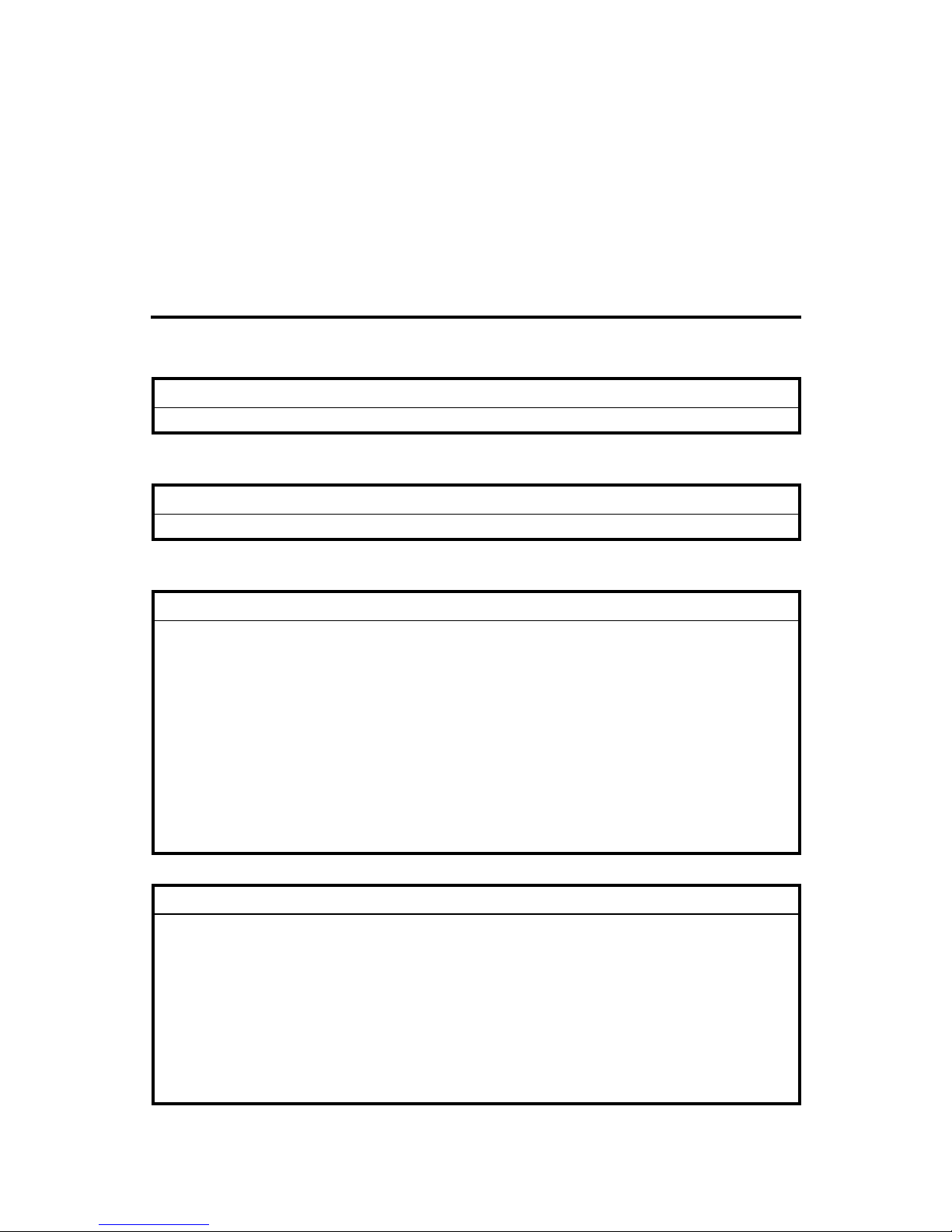
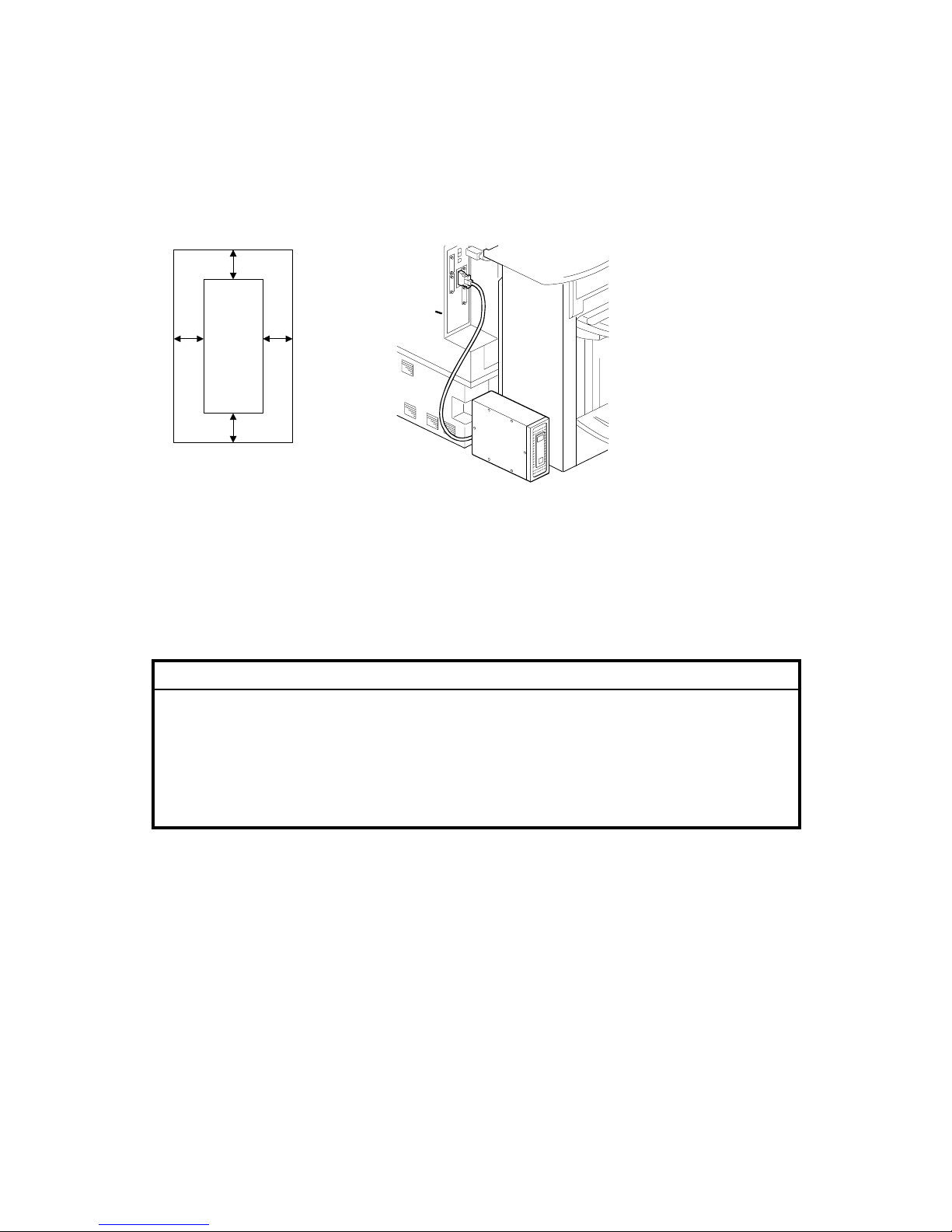
1.1.3 MINIMUM SPACE REQUIREMENTS
Place the machine near the power source, providing clearance as shown.
You may place the machine on the rear side of the finisher as shown in the
illustration.
1.1.4 POWER REQUIREMENTS
!CAUTION
1. Insert firmly the plug in the outlet.
2. Avoid using an outlet extension plug or cord.
3. Ground the machine. Avoid using a 3-prong adapter in a 2-hole ungrounded
outlet.
4. Use the supplied AC power cord with this product.
1. Input voltage level: 100 – 240V, 50-60Hz; 3A
2. Do not put anything on the AC power cord.
Front Panel
Back Panel
100 mm
100 mm
100 mm
100 mm
Left Panel
Right Panel
G815I906.WMF
G815R022.WMF
Page 10

20 March, 2006 INSTALLATION FLOW CHART
1-3
InstallationInstallationInstallation
1.2 INSTALLATION FLOW CHART
Recommended installation steps are as follows:
Make sure that the copier
is ready to use.
Unpack the E-7000
Connect the E-7000
to the copier
Print Test Pages and a
Configuration Page
The site administrator connects
the E-7000 to the network
and verifies the connections.
The site administrator installs user
software on networked computers
that print to the E-7000.
Finished
Select the language and
do the minimum setup
The site administrator
configures the setup options.
The site administrator performs
the color calibration.
G815V900.WMF
Page 11

MACHINE INSTALLATION 20 March, 2006
1-4
1.3 MACHINE INSTALLATION
1.3.1 SETTING CUSTOMER EXPECTATIONS
Before installation, the customer should be informed of the following:
• Some nodes on the network may be unavailable for up to one hour.
• The copier may be unavailable for up to one hour
• The site administrator should be available during the installation for network
connectivity.
• Equipment downtime and impact on the network can be minimized if the site
administrator installs a network connector for the E-7000 and confirms network
connection for the E-7000 installation.
• The site administrator should have a networked computer available during the
installation. The appropriate software should already be installed.
Documentation for the networked computer and the network operating software
should be available.
• The site administrator should install the user software shipped with the E-7000
(user documentation is also included) onto the networked PCs and Mac OS
computers that will print to the E-7000.
NOTE: This guide covers hardware installation and service. It provides general
information on connecting the E-7000 to the customer’s network. For
network setup and configuration information, refer the site administrator to
the Configuration and Setup manual.
Page 12

20 March, 2006 MACHINE INSTALLATION
1-5
InstallationInstallationInstallation
1.3.2 UNPACKING THE E-7000
1. Open the box and remove the packing material.
2. Remove the contents from the top container. Inspect the contents for visible
damage. The top container should include the following items:
3. Give the Media Package to the site administrator.
4. Take the remaining components out of the top container.
5. Remove the top container and any packing materials.
6. Carefully lift the E-7000 out of the box.
G815I901.WMF
• [A] AC Power Cord
• [B] Interface Cable
• [C] Extension Card
• [D] Fierydriven Keytops
• [E] Fierydriven Logo
• [F] Base for Keytop
• [G] Media Package
[A]
[B]
[C]
[D]
[E]
[F]
[G]
Page 13
MACHINE INSTALLATION 20 March, 2006
1-6
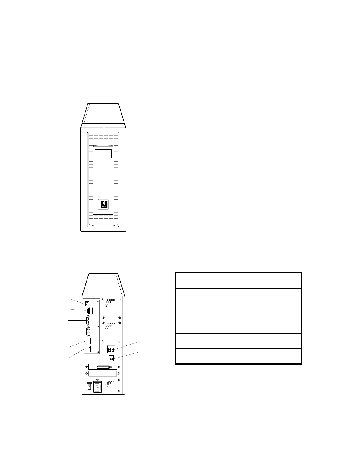
1.3.3 FRONT AND BACK PANELS
After unpacking the E-7000, familiarize yourself with the front and back panels
before you connect the E-7000 to the copier.
• Front Panel
• Back Panel
Color Controller
E-7000
driven
G815R001.WMFMF
ON
1 2ON1 2
G815R002.WMF
A Diagnostic LEDs (for service use only)
B Service Switches (for service use only)
C Video Interface
D Power Connector
E Power Switch
F Not Used
G RJ-45 Connector
(10BaseT/100BaseTX/1000BaseT)
H Not used (Monitor port)
I Not used (Serial Port)
J USB Ports
K Not used (USB Type B port)
[A]
[B]
[C]
[D]
[E]
[F]
[G]
[H]
[I]
[J]
[K]
Page 14
20 March, 2006 MACHINE INSTALLATION
1-7
InstallationInstallationInstallation
1.3.4 CONNECTING E-7000 TO THE COPIER
After you unpack the E-7000, connect the E-7000 to the copier before you connect
it to the network. This is to confirm that there are no problems with the hardware
and controller itself.
!WARNING!
Turn the controller main power switch and copier main power switch to off
and disconnect the power cords before you do these procedures.
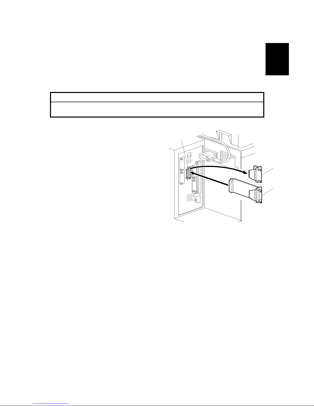
1. Remove the I/F slot cover [A] of Slot C
[C] (this is the slot for the external
controller) (! x 2).
2. Touch a metal surface to remove static
charge from your hands before you
touch the extension card.
3. Insert the extension card [B] into Slot
C [C] and fasten it with the screws. (!
x 2).
NOTE: Make sure that the extension
card is inserted straight and
firmly.
G815R015.WMF
[A]
[B]
[C]
Page 15
MACHINE INSTALLATION 20 March, 2006
1-8
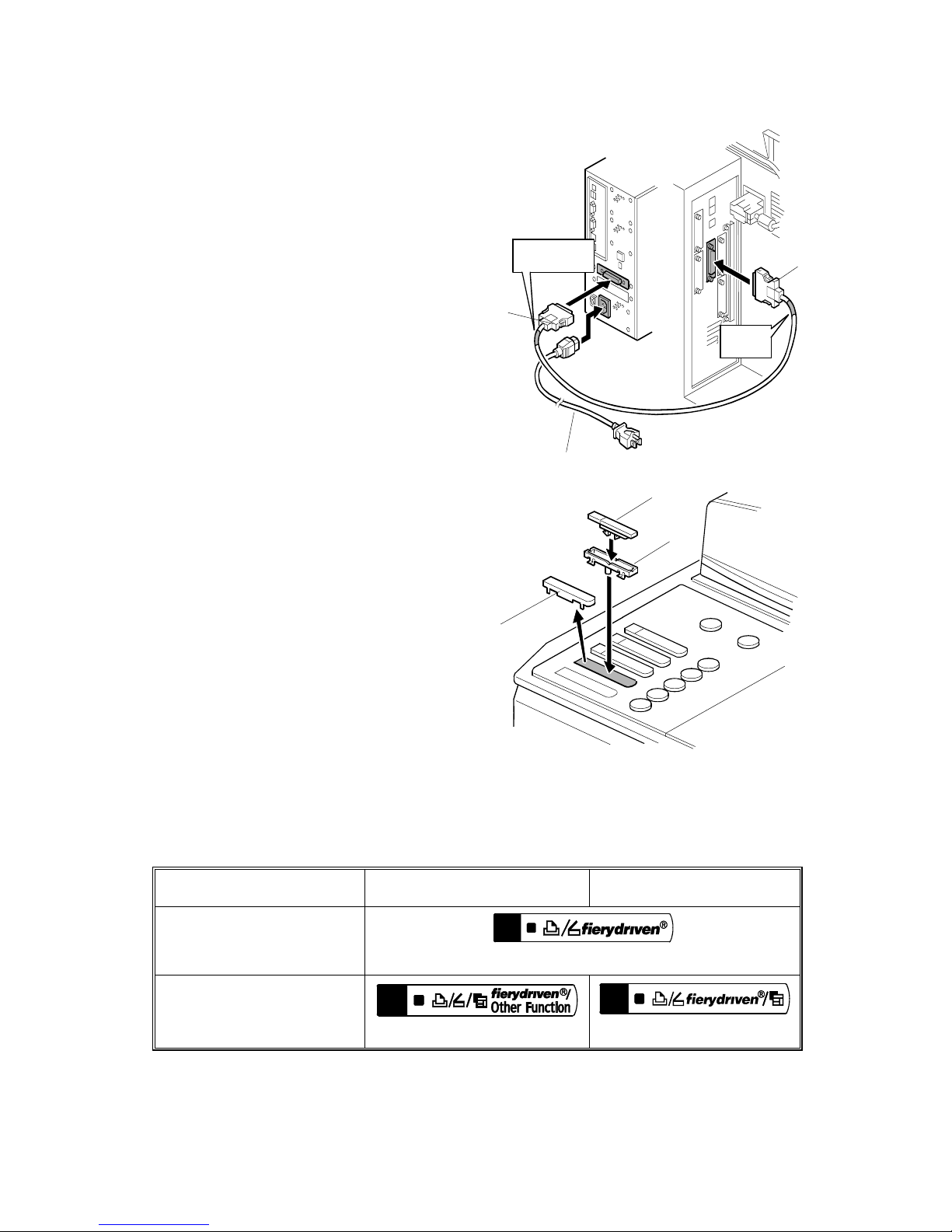
4. Connect the interface cable as follows:
− “Copier Side” [D]:
Connect this to the extension card
and fasten the screws.
− “Controller Side” [E]:
Connect this to the video interface
on the rear of the E-7000.
NOTE: If the interface cable is
connected in the opposite
direction, the copier engine will
fail to communicate with the
controller.
5. Connect the appropriate AC power
cord [F] to the power connector at the
back of the E-7000.
6. On the operation panel of the copier,
remove the Slot Cover [A] and discard
it.
7. Install the base key top [B] and
Fierydriven key top [C] in the position
indicated in the illustration.
Use the correct keytops, as shown in
the table below.
US Model (English)
International Model
(Symbols)
Only the E-7000 is
connected.
B1328890.WMF
The E-7000 and the Copy
Connector Kit (for the
Tandem Copy feature) are
connected.
B1328892.WMF
B1328893.WMF
COPIER
SIDE
CONTROLLER
SIDE
G815R018.WMF
G815R016.WMF
[D]
[E]
[F]
[A]
[B]
[C]
Page 16
20 March, 2006 MACHINE INSTALLATION
1-9
InstallationInstallationInstallation
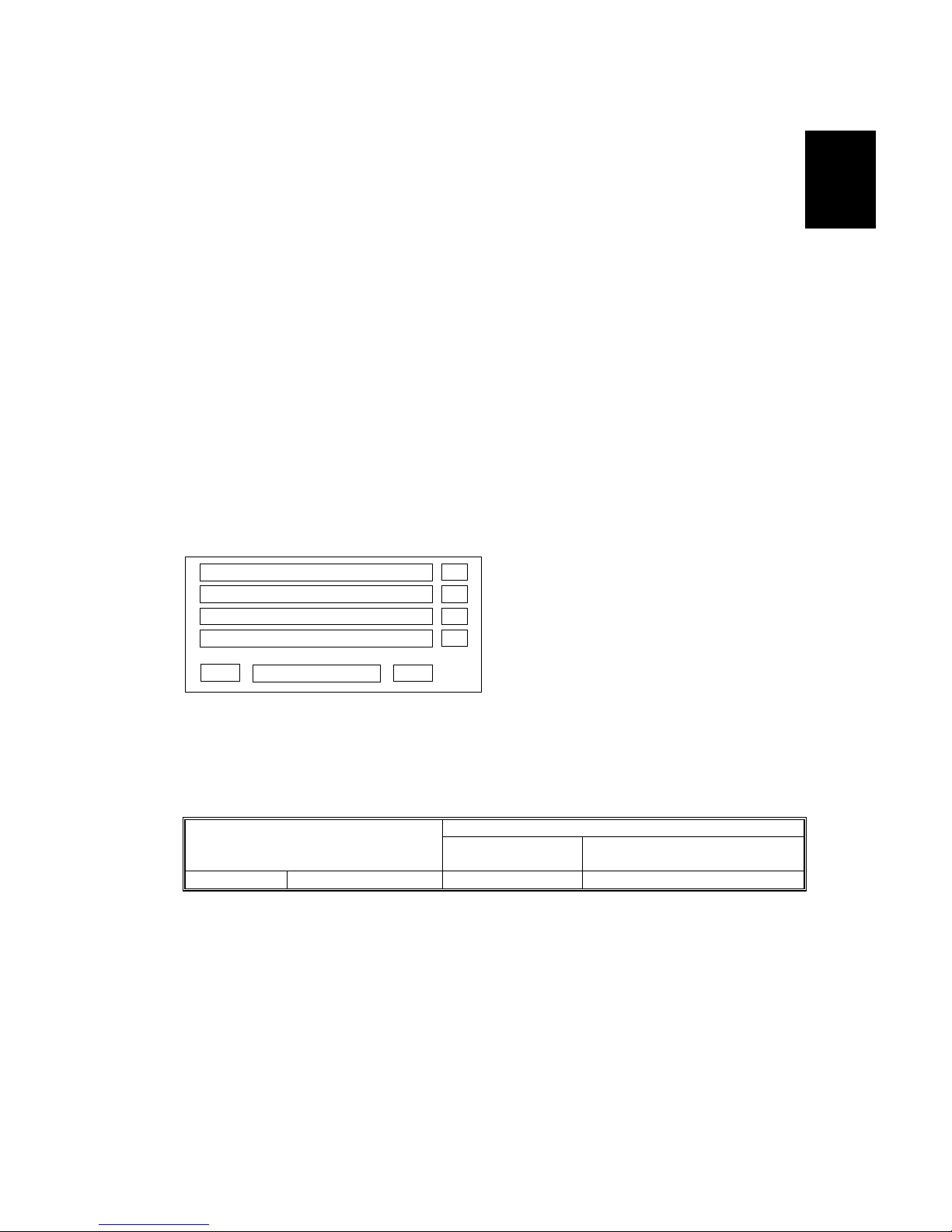
Select Language
English
OK
#
Main Menu/Cancel
$
%
%
%
%
1.3.5 STARTUP AND INITIAL SETUP
1. Connect the power cord of the copier to a power outlet and switch on the copier
main power.
NOTE: 1) The copier must be turned on before you turn the E-7000 on.
2) Make sure that all firmware modules for the copier are updated to
the newest versions. If they are not, update them before you turn on
the E-7000.
(☛ Copier Service Manual)
2. Turn the power switch on the E-7000 back panel to ON.
3. Allow startup to proceed without interruption, while you watch the diagnostic
LEDs on the back panel of the E-7000.
4. When the diagnostic LEDs show ‘00’, go to the copier operation panel and
press the Fierydriven key. ‘Please wait’ may be shown on the copier operation
panel.
5. The language selection screen is shown. (If this screen is not shown, then
press the Fierydriven key again.)
Select the desired language with the down arrow “$” key and up arrow “#”
key, and touch “OK”.
• English
• Dutch
• Spanish
• Italian
• German
• French
NOTE: 1) After you have selected a language, you cannot change the
language unless you do “Factory Defaults (☛ 4.3)” or re-install the
system software.
2) The default settings for the E-7000 depends on the language
selection as follows:
Selected Language & Market Region
English - US
English – UK/Dutch / Spanish/
Italian /German/French
PS Setting Default Paper Sizes
US Metric
Page 17
MACHINE INSTALLATION 20 March, 2006
1-10
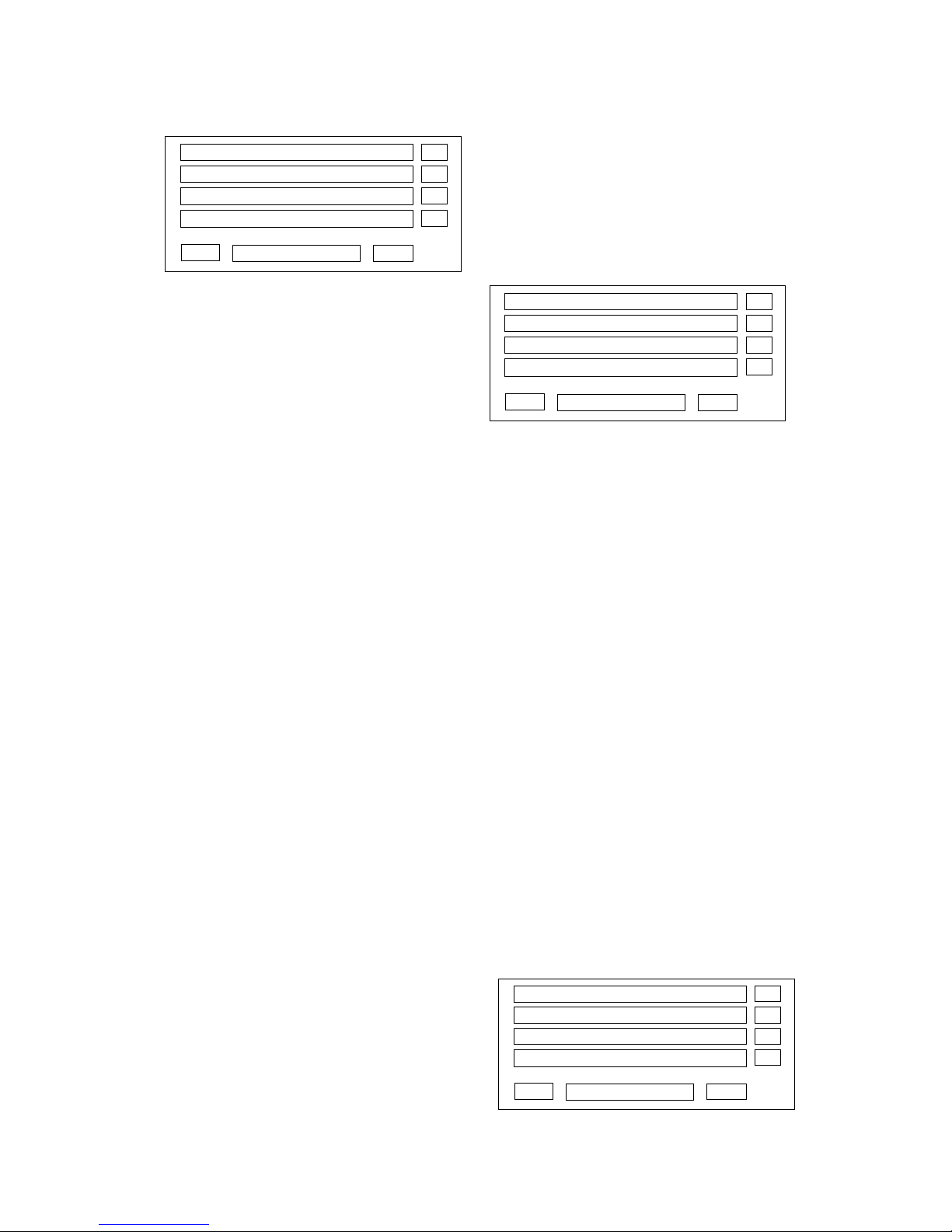
Select Market Region
U.S.
O
K
#
Main Menu/Cancel
$
%
%
%
%
Exit Setup
Server Setup
Network Setup
Printer Setup
#
Main Menu/Cancel
$
%
%
%
%
Exit Setup
Server Setup
Network Setup
Printer Setup
#
Main Menu/Cancel
$
%
%
%
%
If you selected “English” at the language
selection screen, you are prompted to
select the market region. Select either
“US” or “UK” with the down arrow “$”
key and up arrow “#” key, then touch
“OK”.
6. “Please wait…” will be indicated on
the Fiery menu screen, then the Fiery
menu screen will disappear from the
operation panel.
7. Wait for a moment, then press the
Fierydriven key again on the
operation panel. The Setup main
menu will appear on the Fiery menu screen.
NOTE: The E-7000 setup options should be configured later by the site
administrator. However, during the installation, a field technician must
check that the E-7000 controller works correctly with the default
configuration.
Therefore, the next steps show the steps for minimum configuration.
8. “Enter Password” message will appear.
Enter the default administrator password: “Fiery.1”.
9. Touch the keys in the following order, to configure the minimum setup.
1) “Server Setup” key
2) “Main Menu/Cancel” key
3) (When you see “Save Changes for Server Setup / YES”)
“OK” key
4) “Network Setup” key
5) “Exit Network” key
6) (When you see “Save Changes for Server Setup/ YES”)
“OK” key
7) “Printer Setup” key
8) “Main Menu/Cancel” key
9) (When you see “Save Changes for Printer Setup / YES”)
“OK” key
NOTE: If you need to specify the system date and time, enter the Server Setup
menu and set them.
10. Select “Exit Setup”.
Page 18
20 March, 2006 MACHINE INSTALLATION
1-11
InstallationInstallationInstallation
Server Name
Idle
XXXXXMB (Version)
#
Main Menu/Cancel
$
%
%
%
%
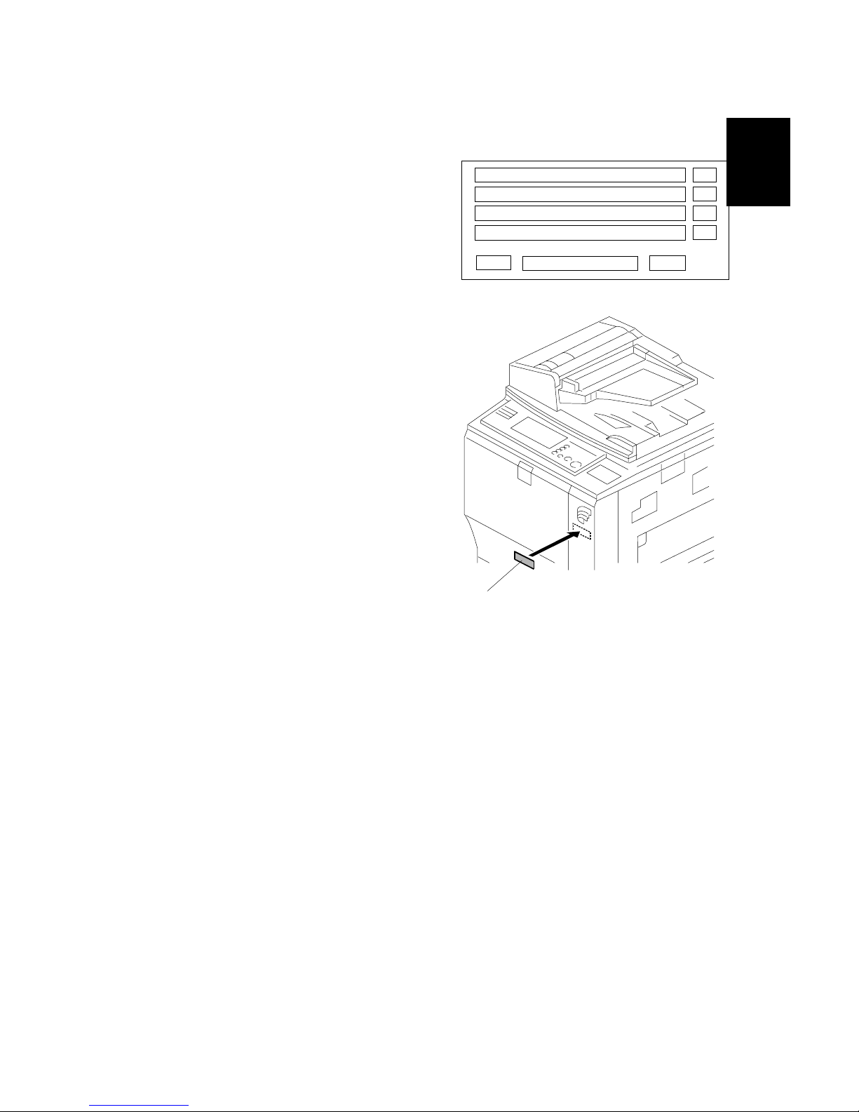
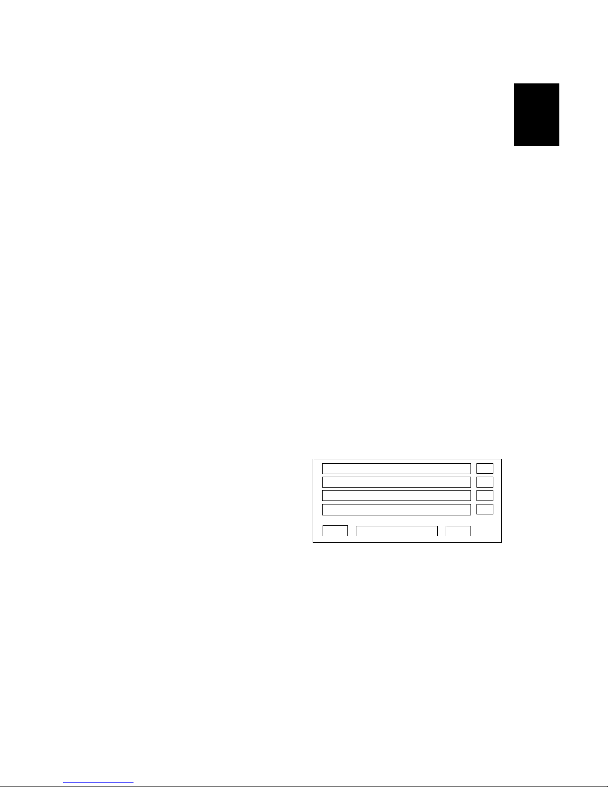
11. The system will reboot. The Fierydriven
key will have no effect until after the
system reboots. To confirm that the
reboot was successful, press the
Fierydriven key. The Fiery Menu
screen will appear on the operation
panel of the copier.
12. Attach the Fiery Decal [A] to the copier
front cover.
G815R024.WMF
[A]
Page 19
MACHINE INSTALLATION 20 March, 2006
1-12
1.3.6 VERIFYING THE CONNECTION (LOCAL TEST PRINT)
After you connect the E-7000 to the copier, print the Test Page and the
Configuration Page to verify that the connection between the E-7000 and the
copier is good.
1. Make sure that the copier is not in use.
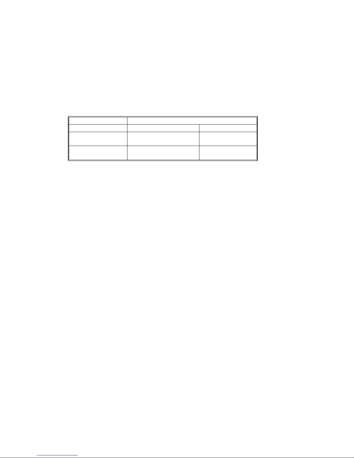
2. Check the settings in the following table, and make sure that Letter or A4 paper
is loaded in at least one of the paper trays of the copier.
PS Setting Default Paper Size
Setup Option “US” “Metric”
Configuration
Page requires…
Letter A4
PS Test Page
requires…
Letter A4
3. On the operation panel of the copier, press the Fierydriven key to access the
printer initial menu screen.
4. Access the menu list. To do this, touch the “Main Menu/Cancel” key, and
select “Print Pages”.
5. Print the following pages:
• Configuration Page
• PS Test Page
6. Examine the quality of the test pages.
• All patches should be visible, but it is acceptable if they are very faint in the
5% and 2% ranges.
• Each patch set should show uniform gradation from patch to patch as the
shade lightens from 100% to 0%.
• Poor image quality may indicate that the copier needs service. For more
information, see the documentation provided with the copier.
Page 20
20 March, 2006 MACHINE INSTALLATION
1-13
InstallationInstallationInstallation
Exit
Server Setup
Network Setup
Printer Setup
#
Main Menu/Cancel
$
%
%
%
%
1.3.7 VERYFYING CONNECTION TO THE NETWORK
The E-7000 provides twisted pair connectivity to an Ethernet network.
Cable requirements:
• 10BaseT (Ethernet): Unshielded Twisted Pair (UTP), Category 3 or higher
• 100BaseTX (Fast Ethernet): UTP, Category 5 or higher (4-pair/8-wire, short
length)
• 1000BaseT (Gigabit Ethernet): UTP, Category 5e or higher (4-pair/8-wire,
short-length)
NOTE: If the print engine is 230V, use a shielded network cable.
1. Turn off the E-7000 power before connecting the E-7000 to any network
device.
2. Connect the network cable to the RJ-45 connector (upper connector) on the E-
7000. (The lower connector cannot be used.)
3. Make sure that the copier power is switched on.
4. Turn the power switch on the E-7000 back panel to ON.
5. Allow startup to proceed without interruption, while you watch the diagnostic
LED on the back panel of the E-7000. When the diagnostic LEDs show ‘00’, go
to the copier operation panel.
6. Configure the Setup options.
1) Press the Fierydriven key on the copier operation panel. (‘Please wait’ may
be shown on the copier operation panel. If the next screen is not shown after
‘Please wait’, then press the Fierydriven key again.)
2) Touch the “Main Menu/Cancel” key.
3) Touch the down arrow “$” key.
4) Select “Run Setup”.
5) Touch “OK”.
6) Wait for a while and then press the
Fierydriven key again.
7) Wait until the setup main screen
appears.
8) Ask the site administrator to configure the Setup options.
NOTE: It is the site administrator’s responsibility to configure the correct setup
options for the network and user environment. The default settings in
the setup may be adequate, but they may not be optional for the user’s
environment. Refer the site administrator to the Configuration and
Setup manual for setup information.
7. After configuring the Setup options, verify the network connection.
Ask the site administrator to install the printer driver on a client PC, and to
make a test print from that PC.
Page 21
INSTALLING OPTIONAL FEATURES 20 March, 2006
1-14
1.4 INSTALLING OPTIONAL FEATURES
1.4.1 OVERVIEW
The system software for the E-7000 contains the following optional features:
• EFI Spot-On
• EFI Hot Folders
• EFI Auto Trap
Initially, the above three optional functions cannot be used. When the customer
purchases any of these functions, a hardware USB dongle which includes a license
for the optional feature will be provided.
After the license for the feature is transferred to the E-7000, the dongle will be
locked to that particular E-7000 (a unique value will be written to the dongle).
• To transfer the license from the dongle to the E-7000, you turn off the E-7000
power, connect the dongle, turn on the E-7000 power, wait for the E-7000 to get
to the idle condition, then remove the dongle. The feature is now activated. There
is a detailed procedure on the next page.
After this, the same dongle cannot be used on another E-7000, unless the license
is first removed from the original E-7000 using that dongle. (You must use the
same dongle.)
• To remove the license from the E-7000, do exactly the same procedure that you
use when you transfer the license from the dongle to the E-7000. This
deactivates the feature.
When the feature is removed from the original E-7000, the unique value will be
removed from the dongle. The dongle can now be used on another E-7000.
If a dongle that has already a unique value (had its unit ID locked to a E-7000) is
inserted into another E-7000 unit, the dongle will have no effect.
The number of times the license can be removed from the E-7000 is limited as
shown in the table below. (Activate 4 times and deactivate 3 times.) When this limit
is reached, the dongle can no longer be used to remove the license, so the license
will stay on the E-7000. If a dongle is inserted to remove a feature but the limit has
been reached, there will be no effect.
E-7000 Power Turned On (or
E-7000 Rebooted) with
Dongle Connected
Activates/Deactivates the
feature on the E-7000
License Transferred
to
1st time Activates E-7000
2nd time Deactivates Original Dongle
3
rd
time Activates E-7000
4
th
time Deactivates Original Dongle
5
th
time Activates E-7000
6
th
time Deactivates Original Dongle
7
th
time Activates E-7000
8
th
time and after No effect No effect
Page 22
20 March, 2006 INSTALLING OPTIONAL FEATURES
1-15
InstallationInstallationInstallation
1.4.2 ACTIVATE / DEACTIVATE AN OPTIONAL FEATURE USING A
DONGLE
The optional feature dongle can be used to either activate or deactivate a feature.
The operation for both of these procedures is exactly the same, and the successful
activation or deactivation can be confirmed by printing the configuration page.
The purpose of the ability to remove the license (deactivation) is to handle cases
where the license was accidentally installed on the wrong E-7000 unit.
Immediately after the E-7000 main power is turned on or the E-7000 is rebooted,
the E-7000 checks for the presence of the feature activation dongle.
1. Print the configuration sheet of the E-7000. (☛ 2.3)
2. With the configuration sheet, check the condition of the optional feature that
you will activate/deactivate. (Disabled/Enabled).
3. Shut down the E-7000 and turn the power of the E-7000 OFF. (☛ 2.1.3)
4. Insert the dongle in a USB port.
(There are two USB ports in the back panel of the E-7000. Any of the USB
ports can be used.)
5. Make sure that the copier main power is already ON.
6. Turn the power switch of the E-7000 ON.
7. Wait for the E-7000 to come to the idle status.
During this startup sequence, the optional feature will be activated/deactivated.
NOTE: If the E-7000 already has a particular feature activated, and a new
dongle for the same feature is inserted, the license will not be affected
and the new dongle will remain active.
If the E-7000 already has a particular feature activated and the
matching dongle is inserted, the feature will be removed, and the
dongle can then be re-used on another E-7000 unit.
8. Remove the dongle from the USB port.
!CAUTION
Do not forget to remove the dongle at this time.
If you leave the dongle in the USB port and the E-7000 main power is
restarted or the E-7000 is rebooted, then the condition of the optional
feature will be reversed. (For example, if you wanted to activate the feature,
it is now deactivated.) The only exception is that after you activate a feature
for the 4th time, it cannot be deactivated.
Page 23
INSTALLING OPTIONAL FEATURES 20 March, 2006
1-16
9. Print a configuration sheet (☛ 2.3).
10. On the configuration sheet, check if the desired optional feature is
activated/deactivated.
If you have activated an optional feature, keep the configuration sheet. You
may need it later for troubleshooting purposes, as shown in the following
caution.
!CAUTION
After an optional feature has been activated, the optional feature license
information is kept inside the U38 chip on the video board of the E-7000.
If the U38 chip becomes defective, the following are needed as evidence in
order to get a new U38 chip and optional feature dongle:
• The defective U38 chip
• The configuration sheet that shows that the defective U38 chip had
the optional feature license installed.
Therefore, always print a configuration sheet and keep it when you activate
a new optional feature on the E-7000.
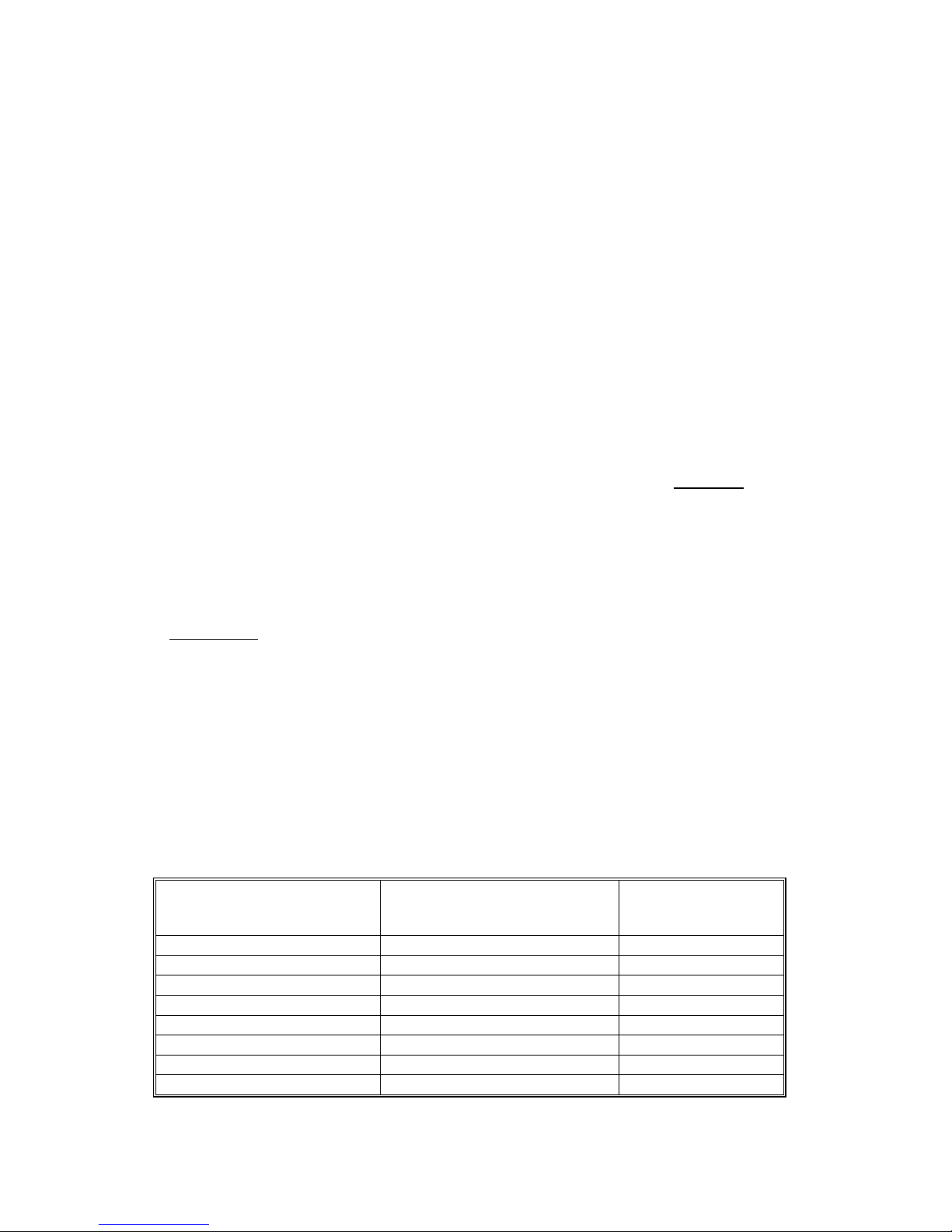
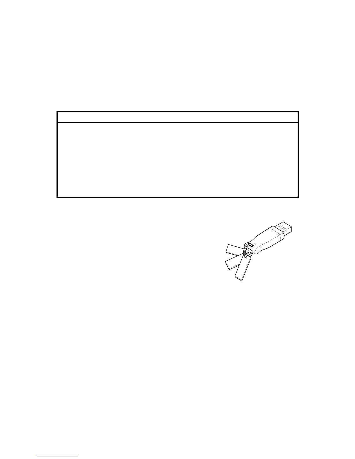
11. 3 tags with 6 labels are attached to each optional feature dongle.
a) Optional Feature Name: Printed
b) Optional dongle serial number: Printed
c) Installed Controller Model Name: Blank
d) Installed Controller Serial Number: Blank
e) 4 check boxes for Activation: Not checked
f) 3 check boxes for Deactivation: Not
checked
For the labels c) to f), you can fill in the related
information or check the boxes, if you want to keep a record of the status of
each dongle.
G815R023.WMF
Page 24

20 March, 2006 START-UP, SHUT-DOWN, AND REBOOT PROCEDURES
2-1
Replacement
Server Name
Idle
XXXXXMB (Version)
#
Main Menu/Cancel
$
%&
%&
%&
%&
2 GENERAL OPERATIONS FOR SERVICING
2.1 START-UP, SHUT-DOWN, AND REBOOT
PROCEDURES
The copier and the E-7000 have separate power switches. During normal
operation, you can leave the E-7000 switch in the ON (|) position.
If you turn off the main power of the copier, this shuts down the E-7000 correctly.
If you turn the copier power back on, this will wake up the E-7000 correctly.
2.1.1 STARTING THE COPIER AND THE E-7000
1. Turn on the copier using the main power switch.
2. Turn on the E-7000 using its power switch.
The E-7000 takes less than 3 minutes to reach the idle condition. The copier
may need several minutes to warm its components.
NOTE: Always turn on the copier main power first. If the copier main power is
off (or disconnected from the E-7000), the E-7000 will begin to start up
but it will shut down automatically before it reaches the idle condition.
This feature protects the E-7000 from incorrect shutdown.
3. After the E-7000 and the copier
become idle, press the Fierydriven
key. The Fiery menu screen will
appear on the copier operation
panel.
Page 25

START-UP, SHUT-DOWN, AND REBOOT PROCEDURES 20 March, 2006
2-2
Restart Server
Shut Down System
Reboot System
#
Main Menu/Cancel
$
%
%
%
%
2.1.2 SHUTTING DOWN THE COPIER AND THE E-7000
1. Make sure the On indicator on the copier operation panel is off. If not, press the
operation switch and wait until the On indicator is off.
NOTE: Do not turn off the main power switch of the copier when the On
indicator is on or blinking. Failure to observe this may result in damage
to the copier’s HDD or memory, leading to a malfunction.
2. Turn the main switch of the copier OFF.
3. Wait for the E-7000 diagnostic LEDs to turn off.
The E-7000 is now ready to turn back on automatically when the copier power
is turned on.
4. If the E-7000 is being taken out of service, turn off the E-7000 using its power
switch. (For example, if someone needs to move the E-7000, disconnect cables,
or open the chassis.)
2.1.3 SHUTTING DOWN THE E-7000 ONLY
1. Press the Fierydriven key on the operation panel of the copier. The Fiery
menu screen appears.
2. Touch the “Main Menu/Cancel” key to
access the menu list.
3. Scroll through the menu list by
touching the down arrow “$” key.
4. Touch the “Shut Down” key, then
press the “Shut Down System” key.
5. Wait for the diagnostic LEDs on the E-7000 to turn off.
6. Turn off the E-7000 using its power switch.
The Fiery will remain OFF even when the copier power is turned on or on/off.
Page 26

20 March, 2006 START-UP, SHUT-DOWN, AND REBOOT PROCEDURES
2-3
Replacement
Restart Server
Shut Down System
Reboot System
#
Main Menu/Cancel
$
%
%
%
%
Restart Server
Shut Down System
Reboot System
#
Main Menu/Cancel
$
%
%
%
%
2.1.4 RESTARTING THE E-7000
When restarting the E-7000 to recover from a problem, try this procedure first.
However, this procedure will only restart the E-7000 application software that is
now running on the system OS. To reboot the system OS (for example, after
downloading a patch), see the next section “Rebooting the E-7000 (☛ 2.1.5)”.
1. Make sure that the E-7000 is not in use.
2. Press the Fierydriven key on the operation panel of the copier. The Fiery
menu screen appears.
3. Press the “Main Menu/Cancel” key to
access the menu list.
4. Scroll through the menu list by
pressing the down arrow “$” key.
5. Touch the “Shut Down” key, then
touch the “Restart Server” key.
6. Wait until the E-7000 becomes idle.
2.1.5 REBOOTING THE E-7000
Use this procedure to reboot the system OS (for example, after downloading a
patch).
1. Make sure that the E-7000 is not in use.
2. Press the Fierydriven key on the operation panel of the copier. The Fiery
menu screen appears.
3. Press the “Menu/Cancel” key to
access the menu list.
4. Scroll through the menu list by
pressing the down arrow “$” key.
5. Touch the “Shut Down” key, then
touch the “Reboot Server” key.
6. Wait until the E-7000 becomes idle.
NOTE: Do not reboot the E-7000 by turning the copier main switch OFF and ON.
Recycling power to the copier does not reboot the E-7000 properly.
Page 27

CANCELLING THE CURRENT PRINT JOB 20 March, 2006
2-4
Server Name
Printing
XXXXXMB (Version)
#
Main Menu/Cancel
$
%
%
%
%
Cancel Job
(User Name)
(Job Name)
#
Main Menu/Cancel
$
%
%
%
%
2.2 CANCELLING THE CURRENT PRINT JOB
When you want to cancel the current print job, do the following:
1. Press the Fierydriven key on the
operation panel of the copier to access
the Fiery menu screen.
2. Press the “Main Menu/Cancel” key to
access the menu list.
3. Press “Cancel Job”.
For how to cancel print jobs, please also
refer to the Configuration and Setup
manual.
2.3 PRINTING THE CONFIGURATION SHEET OR TEST
SHEETS
1. Make sure that the E-7000 is not in use.
2. Press the Fierydriven key on the operation panel of the copier to access the
Fiery menu screen.
3. Press the “Main Menu/Cancel” key to access the menu list.
4. Touch the ”Print Pages” key, then touch the desired key.
• “PS Test Page”
• “Configuration Page”
Page 28

20 March, 2006 RUNNING THE E-7000 SETUP
2-5
Replacement
Exit Setup
Server Setup
Network Setup
Printer Setup
#
Main Menu/Cancel
$
%
%
%
%
2.4 RUNNING THE E-7000 SETUP
The following procedures show how to access the Setup menu from the Fiery
menu screen.
NOTE: When the network settings (protocol, IP Address, etc.) are already
configured and the “Enable Web Service” option is set to ON, you can also
configure the E-7000 setup from “Fiery Web Setup”. To do this, use a web
browser on a personal computer which is connected on the network.
For more detailed instructions, please refer to the Configuration and Setup
manual.
NOTE: When you try to get access to the Setup menu, you are always asked to
input an administrator password. (The default password is “Fiery.1”) Ask
the site administrator to input the administrator password when you must
get access to the Setup menu.
2.4.1 TO ACCESS THE SETUP MENU
1. Make sure that the E-7000 is not in use.
2. Press the Fierydriven key on the operation panel of the copier to access the
Fiery menu screen.
3. Press the “Main Menu/Cancel” key to access the menu list.
4. Scroll through the menu list by pressing the down arrow “$” key.
5. Touch the ”Run Setup” key.
6. When you are prompted “Continue to
Setup? / YES”, press “OK”.
The Fiery menu screen will disappear.
7. Press the Fierydriven key to access
the Fiery menu screen.
8. You may be asked to enter an administrator password. (Ask the site
administrator to enter the password. The default password is “Fiery.1”)
9. The main setup screen appears.
For the details of each setup option value, refer to the Configuration and Setup
manual.
2.4.2 TO EXIT FROM THE SETUP MENU
1. At the main setup screen, touch ”Exit Setup” key.
The Fiery menu screen will disappear.
2. Press the Fierydriven key to access the Fiery menu screen.
Page 29

GENERAL CAUTION 20 March, 2006
3-6
3 REPLACEMENT
3.1 GENERAL CAUTION
!
WARNING
Turn off the power and unplug the E-7000 before attempting any of the
procedures in this section.
• Before accessing internal components, position the E-7000 so that it is resting on
its right-hand side on a flat, anti-static surface.
Page 30

20 March, 2006 NAMES OF MAIN PARTS/UNITS
3-7
Replacement
3.2 NAMES OF MAIN PARTS/UNITS
Name Refer to Name Refer to
A Base of case - N Video board ☛ 3.4.1
B Front cover - O Video board bracket ☛ 3.4.1
C Fierydriven keytops ☛ 1.3.4 P 14-pin LED cable ☛ 3.4.2, 3.4.6
D Fierydriven decal ☛ 1.3.4 Q Motherboard ☛ 3.4.6
E Base for keytop ☛ 1.3.4 R CPU cooling assembly ☛ 3.4.8
F Extension card ☛ 1.3.4 S CPU ☛ 3.4.8
G AC power cord ☛ 1.3.4 T Power supply unit ☛ 3.4.4
H Interface cable ☛ 1.3.4 U Fan(s) ☛ 3.4.5
I HDD ☛ 3.4.3 V Diagnostic LED board ☛ 3.4.2
J HDD bracket ☛ 3.4.3 W Bracket K Memory ☛ 3.4.7 X U38 chip ☛ 3.4.1
L IDE cable ☛ 3.4.3, 3.4.6 Y U39 chip ☛ 3.4.1
M Side cover ☛ 3.3.1 Z Lithium Battery ☛ 3.4.9
G815V903.WMF
[A]
[B]
[C]
[D]
[E]
[F]
[G]
[H]
[I]
[J]
[K]
[L]
[M]
[N]
[O]
[P]
[Q]
[R]
[S]
[T]
[U]
[V]
[W]
[X]
[Y]
[Z]
Page 31

COVER REMOVAL 20 March, 2006
3-8
3.3 COVER REMOVAL
3.3.1 SIDE COVER FOR THE E-7000
[A]: Side cover (! x 6)
G815R003.WMF
Page 32

20 March, 2006 UNIT REMOVAL
3-9
Replacement
3.4 UNIT REMOVAL
3.4.1 VIDEO BOARD
[A]: Video board with bracket (! x 2)
[B]: Bracket (! x 2)
[C]: U38 Chip
[D]: U39 Chip
NOTE: The video board that you use as a
spare part does not include the
U38 and U39 ROMs.
When you replace the video board,
do not forget to move the U38 and
U39 ROMs from the old board to
the new board.
• U38 Chip:
Contains option upgrade information and licensing information for the E-7000.
• U39 Chip:
Contains the following printer-related configuration settings.
• Shift Operation (E-7000 Printer Setup)
• Bypass Tray Priority (E-7000 Printer Setup)
• Bypass Tray Paper Size (Copier User Tool Menus)
• Paper Tray Priority: Printer (Copier User Tool Menus)
• Printer Auto Reset Timer (Copier User Tool Menus)
• Printer Authentication Mode (Copier User Tool Menus)
• Output Tray Priority: Printer (Copier User Tool Menus)
G815R007.WMF
G815R019.WMF
[A]
[B]
[C]
[D]
Page 33

UNIT REMOVAL 20 March, 2006
3-10
3.4.2 DIAGNOSTIC LED BOARD
[A]: 14-pin LED cable (" x 1)
[B]: LED board
Notes for Re-assembling:
• The red line on the LED cable must face
down when you connect the cable to the
LED board (see the illustration).
3.4.3 HARD DISK DRIVE (HDD)
[C]: IDE cable (" x 1)
[D]: Power cable (" x 1)
[E]: HDD with bracket (! x4)
[C]: HDD (! x4)
Notes for Re-assembling:
• [C]: Make sure to connect the black side
(“MASTER” side) of cable to the HDD.
G815R009.WMF
ULTRA ATA133 CABLE
MASTER
G815R008.WMF
[A]
[B]
[C]
[D]
[F]
[E]
Page 34

20 March, 2006 UNIT REMOVAL
3-11
Replacement
3.4.4 POWER SUPPLY UNIT
Power supply cable (" x 4).
• [A]: Harness from Main Power
Switch.
• [B]: HDD power connector from
HDD
• [C]: 4-pin power connector from
the J1 socket on the
motherboard.
• [D]: 20-pin power connector
from the JB3 socket on the
Motherboard.
• [E]: Power Switch
[F]: Power supply unit (! x 5)
3.4.5 FAN
Cables (" x2):
• [G-2] from FAN2
• [G-3] from FAN3
[FAN2]: Fan (! x 4)
[FAN3]: Fan (! x 4)
Notes for Re-assembling:
• Connect the [G-2] cable (Short) to FAN2
on the motherboard.
• Connect the [G-3] cable (Long) to FAN3
on the motherboard.
G815R011.WMF
G815R012.WMF
[A]
[B]
[C]
[D]
[E]
[F]
[G-2]
[G-3]
[
FAN2
]
[FAN3]
Page 35

UNIT REMOVAL 20 March, 2006
3-12
3.4.6 MOTHERBOARD
1. Video board (☛ 3.4.1)
2. Fan case (☛ 3.4.5)
3. Cables (" x4):
• [A]: 4-pin power connector from J1
• [B]: 20-pin power connector from J18
• [C]: Fan cable from FAN2
• [D]: Fan cable from FAN3
• [E]: IDE cable from JB2
• [F]: LED cable from J29
4. Screws (! x 5)
5. Memory (☛ 3.4.7)
6. CPU Cooling Assembly (☛ 3.4.8)
7. CPU (☛ 3.4.8)
NOTE: When you replace the
motherboard, remove the
CPU and memory and
attach them to the new
motherboard. (☛ 3.4.8)
Notes for Re-assembling:
• Make sure of where to connect
the connectors for each cable.
Make sure that all connectors are
inserted firmly in the sockets.
Also, do not put the connectors in
the sockets the wrong way
around.
No. Connector Location
[A] 4-pin power connector J1
[B] 20-pin power connector J18
[C] Fan cable from FAN2 FAN2
[D] Fan cable from FAN3 FAN3
[E] IDE cable JB2
[F] LED cable J29
[G] CPU fan cable FAN1
[H] Memory DIMM1
ULT RA ATA133 CABL E
SYSTEM
G815R010.WMF
J1
FAN1
J29
PCI1PCI2
JB3 JB2
J18
DIMM1
DIMM2
FAN2
FAN3
G815R014.WMF
[A]
[B]
[C]
[D]
[E]
[F]
[A]
[B]
[C]
[D]
[E]
[F]
[G]
[H]
Page 36

20 March, 2006 UNIT REMOVAL
3-13
Replacement
3.4.7 MEMORY - 512 MB DIMM
1. Push outward on the levers [A-1], [A-2]
on each side of the DIMM.
2. Slide the DIMM [B] straight out of the
socket.
Notes for Re-assembling:
• Always attach the DIMM [D] to the
DIMM1 socket (closer to the CPU unit).
• Gently slide the DIMM straight down into
the socket and press so that the levers
lock the DIMM into place. Make sure that
the levers close securely around the
ends of the DIMM.
• DIMMs fit in the socket only one way.
The two notches [D] on the bottom of the
DIMM should line up with the notches in
the socket.
3.4.8 CPU AND COOLING ASSEMBLY
You can replace the following parts.
• Cooling Assembly [D] only
• CPU [F] and Cooling Assembly [D] (as a set): If you replace the CPU, you must
replace the cooling assembly also, as a set.
The cooling assembly consists of a fan with heat sink and a clip assembly.
NOTE: 1) Be careful not to damage the motherboard, the CPU, or the CPU socket
when you replace the cooling assembly.
Remove the memory before you remove the cooling assembly.
2) When you want to replace the CPU, replace the CPU and the cooling
assembly as a set.
This is very important, because the thermal pad that is attached to a
new heat sink will make a good contact between the CPU and the heat
sink when heated.
If you attach a used cooling assembly to a new CPU by mistake, the
heat sink will not contact the CPU properly, and this will cause the CPU
to overheat.
G815R006.WMF
[A-1]
[B]
[A-2]
Page 37

UNIT REMOVAL 20 March, 2006
3-14
Cooling assembly removal procedure:
1. Remove the CPU fan cable [A] from
the motherboard FAN1 (" x 1).
2. Open the clip levers [B-1] [B-2] by
lifting them up.
3. Insert a flathead screwdriver
between fan shroud and clip frame
[C]. Push the screwdriver down until
it hits the clip hook.
4. Push down on the clip hook and at
the same time turn the screwdriver
towards the fan heat sink to free the
clip hook. Repeat this process for
the remaining clip hooks.
5. Remove the fan heat sink. [D].
Notes for re-assembling the CPU cooling assembly:
• Make sure to close the clip levers one at a time. Close the clip levers [B-1] while
holding the topside of the fan heat sink with your other hand. Then, close the clip
lever [B-2], while holding the topside of the fan heat sink with your other hand.
CPU removal procedure:
1. Lift the CPU socket lever [E] to release
the CPU [F] from the socket.
2. Grasp the CPU [F] by its edges and
gently lift it from the socket.
Notes for re-attaching the CPU:
• Check the location of the arrow [G] on
the CPU [F] when you insert the CPU [F]
into the socket [H]. (See the illustration.)
• Be careful not to bend the pins when you
insert the CPU into the socket.
• Set the CPU in the socket completely and without forcing it.
• Close the socket lever [E] to secure the CPU [F] in place.
G815R004.WMF
G815R005.WMF
[A]
[B-1]
[C]
[B-2]
[D]
[E]
[F]
[G]
[H]
Page 38

20 March, 2006 UNIT REMOVAL
3-15
Replacement
3.4.9 LITHIUM BATTERY
!CAUTION
There is danger of explosion if the battery is replaced with the incorrect
type. Replace with only with the same lithium battery supplied as a spare
part.
Discard the used motherboard battery in accordance with the
manufacturer’s instructions and local regulations.
Note for Re-assembling:
• You need to re-configure the system
date and time.
To configure the system date and time,
enter the ‘Server setup’ menu from the
Setup main menu. (☛ 2.4.1)
3.4.10 EXTENSION CARD
1. Extension Card (! x 2), on the copier
Note for Re-assembling:
• Make sure that the extension card is inserted straight.
G815R013.WMF
Page 39

Page 40

20 March, 2006 GENERAL NOTES AND CAUTIONS
4-1
Trouble-
shooting
4 SOFTWARE MAINTENANCE
4.1 GENERAL NOTES AND CAUTIONS
You may use one of the following when you have a problem with the system
software or the HDD.
• Clear Server: Deletes all queued print jobs from the E-7000
• Factory Default: Restores the E-7000 to the factory defaults
• System Software Reinstallation
The following table shows whether the current data on the E-7000 will remain or be
deleted when each of these is used.
“Clear
Server”
“Factory Default”
System Software
Reinstallation / Upgrade
Job Log Deleted Deleted Deleted
Queued Jobs Deleted Deleted Deleted
Scanned Jobs Deleted Deleted Deleted
MailBox Deleted Deleted Deleted
Archived Jobs Deleted Deleted Deleted
FreeForm masters Deleted Deleted Deleted
Resident Fonts Not Deleted Not Deleted Deleted
Downloaded Fonts Not Deleted Deleted Deleted
Language
Selection
Not Deleted Deleted Deleted
Setup Options Not Deleted Deleted Deleted
Patches Not Deleted Not Deleted Deleted
Administrator
Password
Not Deleted Not Deleted Deleted
Option Activation Not Deleted Not Deleted Not Deleted
NOTE: In ‘System Software Reinstallation/Upgrade’, ‘Upgrade’ refers to replacing
the software with a new version. It does not refer to the application of
patches. When you apply a patch, data is not deleted.
Before you use any of the above features, make sure you inform the site
administrator that the indicated data and settings will be deleted and should be reinstalled after the feature has been used.
• Job Log
The list of jobs in the Job Log and all jobs in the queues are deleted. The site
administrator can use Fiery Spooler to save a current list of jobs from the Job
Log (the actual jobs are not saved, only a list of them).
• Queued Jobs
All queued print jobs (in the Print, Hold, and Printed queues) will be deleted.
Page 41

CLEARING THE QUEUED PRINT JOBS IN THE E-7000 20 March, 2006
4-2
• Archived Jobs and Free Form masters
Archived jobs on the E-7000 HDD and FreeForm masters are deleted. The lists
of archived jobs and FreeForm masters are deleted as well.
• Fonts
All fonts on the HDD are deleted when you reinstall the system software.
Resident fonts are reinstalled when you reinstall the system software. Any
customer-supplied fonts will need to be reinstalled by the site administrator using
Fiery Downloader.
• Administrator Password
The administrator password will be deleted when system software is re-installed.
(The administrator password will return to “Fiery.1” after the system software is
re-installed.)
• Configuration
Make sure to print a configuration page before reinstalling the system software.
The Setup configuration will be lost when you reinstall the system software.
Compatibility
When you upgrade the system software, make sure the latest user software is
installed onto all computers that print to the E-7000. Using incompatible versions of
the system and user software can result in system problems.
4.2 CLEARING THE QUEUED PRINT JOBS IN THE E-7000
The ”Clear Server” command allows you to clear all queued print jobs from the E-
7000 – jobs in the E-7000 Print, Hold, and Printed queues. Clear Server also clears
all jobs archived on the E-7000 hard disk, the index of archived jobs, and finally, all
Fiery FreeForm masters and the index of Fiery FreeForm masters.
NOTE: Before using Clear Server, inform the site administrator that data on the E-
7000 hard disk will be deleted.
1. Make sure the E-7000 is not in use.
2. Run the setup menu. (☛ 2.4)
3. Scroll through the setup main menu list by pressing the down arrow “$” key
twice.
4. Touch the “Clear Server” key.
5. When you are prompted “Clear all jobs from all queues?/NO”, press the down
arrow “$” key so that the second line will be changed to “YES”
6. Touch the “OK” key.
The Fiery menu screen will disappear and data will be cleared before the
system restarts.
7. Press the Fierydriven key and check if the E-7000 becomes idle.
Page 42

20 March, 2006 RESTORING THE E-7000 TO FACTORY DEFAULTS
4-3
Trouble-
shooting
4.3 RESTORING THE E-7000 TO FACTORY DEFAULTS
When E-7000 system software is first installed, a backup copy is made
automatically. You or your customer can recover the system from this backup
without having to reload the software from the CD (or USB Flash drive).
Also use “Factory Default” when you want to change the language selection.
NOTE: Before using “Factory Default”, inform the site administrator that all data
(including the downloaded fonts) stored on the HDD and setup options will
be deleted.
NOTE: Performing “Factory Default” will not delete the current administrator
password, which was set for E-7000 (the initial password is “Fiery.1”).
Before performing “Factory Default”, check if the site administrator can
input the current administrator password after the system software is
restored.
If a unique administrator password is already set for the E-7000, but the
site administrator does not remember the password, re-install the system
software from the CD (or from USB flash drive).
1. Make sure the E-7000 is not in use.
2. Print a configuration page (you may refer to this configuration page when you
re-enter the setup options). (☛ 2.3)
3. Run the setup menu. (☛ 2.4)
4. Scroll through the setup main menu list by pressing the down arrow “$” key
twice.
5. Touch the “Factory Default” key.
6. When you are prompted “Reset server to factory settings?/NO”, press the down
arrow “$” key so that the third line will be changed to “YES”
7. Touch the “OK” key.
The Fiery menu screen will disappear.
8. Go to the copier and press the Fierydriven key.
9. The language selection screen will appear. Start to configure the E-7000.
(For details, go to step 23 of the system software installation procedure. ☛ 4.4)
Page 43

SYSTEM SOFTWARE INSTALLATION PROCEDURE 20 March, 2006
4-4
4.4 SYSTEM SOFTWARE INSTALLATION PROCEDURE
4.4.1 OVERVIEW
System software should be installed in the following cases:
• You replace the HDD with a new one (on which the System Software is not
installed)
• You update to a more recent version of the system software (this is not
necessary when you apply a patch; it is necessary when you install a major
version change)
• You have trouble with the system software (i.e. software corruption) and the
problem cannot be solved by performing “Factory Default”.
• The site administrator forgets the administrator password for the E-7000.
The system software is provided as a CD set as follows:
1) System Software CD
System software and an installation program are included.
2) USB Flash Tool CD
This utility will copy the contents of the system software CD to the USB
Flash drive, and at the same time make the USB Flash drive bootable.
There are two ways to install/reinstall system software on the E-7000.
a) Installing system software over the network port.
Connect a PC to the E-7000 directly, or through a hub using a network
cable. Install the system software from the System Software CD.
b) Installing system software by booting the E-7000 from a USB Flash drive.
With the System Software CD, USB Flash Tool CD, and a PC which can
boot from a CD-ROM, first make a bootable USB flash drive that includes
E-7000 system software and the installation program.
At the customer site, connect the USB flash drive to the E-7000’s USB
port and turn the power ON. System installation will be done
automatically.
NOTE: Before you start system installation, give the site administrator the
opportunity to print the Job Log and to save any custom simulations.
Also, print the following from the Print menu.
1. Configuration page
2. Font Lists
Page 44

20 March, 2006 SYSTEM SOFTWARE INSTALLATION PROCEDURE
4-5
Trouble-
shooting
4.4.2 INSTALLING SYSTEM SOFTWARE OVER THE NETWORK
PORT
The system software CD contains the system software and Fiery System Software
Installer. To install system software using the LAN port on the E-7000, you need:
• Either
• Two Ethernet cables and an isolated hub/switch
Cables must be 4-pair/8-wire, short-length Cat 5 (for 100BaseT) or Cat 5e
(for 1000BaseT)
Or
• For 100BaseTX: One Category 5 or higher Ethernet cross-over cable (4-
pin/8-wire, short-length)
For 1000BaseT: One Category 5e or higher Ethernet cross-over cable (4pin/8-wire, short-length)
• A Windows XP/2000 computer with:
• A CD-ROM drive, built in or attached
• Support for 100BaseTX or 1000BaseT
NOTE: This procedure describes using one cross-over cable. Instead of using a
cross-over cable, you may use two Ethernet cables and an isolated
hub/switch. (Do not connect any other devices to the hub/switch. Do not
put the hub/switch on the LAN. Do not use the hub’s optical port or uplink
switch.)
NOTE: If the print engine is 230V, use shielded network cables.
1. Print the Configuration Page. Then perform the Shut Down procedure from the
copier operation panel (☛ 2.1.3)
2. When the E-7000 power is down (that is when the diagnostic LEDs are off),
turn the main switch of the E-7000 to OFF.
3. Disconnect all cables from the E-7000 connector panel. Disconnect the LAN
cable that was connected to the customer’s LAN.
4. Connect the Ethernet cross-over cable to the LAN port and to the Windows
XP/2000 PC.
5. Turn on the PC’s power and insert the System Software CD into the PC’s CDROM drive.
6. If the PC is connected to a wireless LAN, disable the wireless LAN connection.
Otherwise the Fiery Installer cannot find E-7000 automatically.
7. Navigate to the CD-ROM drive and click the icon for the Installer.exe file, if it
does not start automatically.
Page 45

SYSTEM SOFTWARE INSTALLATION PROCEDURE 20 March, 2006
4-6
8. Click Next at the Welcome screen. Read the Software License Agreement and
click the “I Agree” checkbox if you wish to continue the installation process,
then click Next.
9. At the Connection Type screen, make sure Ethernet is selected. Click Next to
advance to the Confirmation screen.
10. Set the E-7000 service switches to the service mode position: ON.
NOTE: The illustration shown on the PC
screen, from the software, is
incorrect. It shows the wrong
direction for turning the service
switches to ON.
Set the E-7000 two service
switches in the upper position as
shown in the illustration in this
page.
11. Turn the main power switch of the
E-7000 to ON and wait 10 seconds.
12. Click Next on the PC screen.
13. At the Installation screen, click Next to
start the installation. Wait while the files are copied and installed.
The progress is slow at first.
For most computers, you must wait approximately 25 minutes – do not cancel.
If you do click Cancel: Click Finish then turn the main power switch of the E7000 to OFF. Wait 10 seconds, and then repeat this procedure from the
beginning. If the installation terminates abnormally, you may need to reboot
the PC also.
14. Click Exit when the screen shows that the installation is successful. Remove
the System Software CD from the PC.
15. Turn the main power switch of the E-7000 to OFF.
16. Set the service switches in the normal position (not ON).
17. Disconnect the cross-over cable from the LAN port and
the Windows XP/2000 PC.
18. Reconnect all cables that you removed earlier from the E7000 panel.
19. Turn on the main switch of the copier.
20. Turn on the main power switch of the E-7000.
21. Allow startup to proceed without interruption while you watch the diagnostic
LEDs on the back panel of the E-7000.
ON
1 2ON1 2
G815R020.WMF
G815R021.WMF
Page 46

20 March, 2006 SYSTEM SOFTWARE INSTALLATION PROCEDURE
4-7
Trouble-
shooting
Select Language
English
OK
#
Main Menu/Cancel
$
%
%
%
%
Select Market Region
U.S.
O
K
#
Main Menu/Cancel
$
%
%
%
%
Exit Setup
Server Setup
Network Setup
Printer Setup
#
Main Menu/Cancel
$
%
%
%
%
22. When the diagnostic LEDs show ‘00’, go to the copier operation panel and
press the Fierydriven key. ‘Please wait’ may be shown on the copier operation
panel.
23. The language selection screen is shown. (If this screen is not shown, then
press the Fierydriven key again.)
Select the desired language by using the down arrow “$” key and up arrow
“#” key, and touch “OK”.
• English
• Dutch
• Spanish
• Italian
• German
• French
NOTE: 1) After you select a language, you cannot change the language unless
you do “Factory Defaults (☛ 4.3)” or re-install the system software.
2) The default settings for the E-7000 depend on the language
selection as follows:
Selected Language & Market Region
English - US
English – UK/Dutch / Spanish/
Italian /German/French
PS Setting Default Paper Sizes
US Metric
If you selected “English” at the language
selection screen, you are prompted to
select the market region. Select either
“US” or “UK” by using the down arrow
“$” key and up arrow “#” key, then
touch “OK”.
24. “Please wait…” will be shown on the
Fiery menu screen. Then the Fiery
menu screen will disappear from the
operation panel.
25. Wait for a short time, then press the
Fierydriven key again on the
operation panel. The Setup main
menu will appear on the Fiery menu screen.
26. “Enter Password” will appear.
Enter the default administrator password: “Fiery.1”.
27. Input the customer’s settings from the Configuration Page that you printed
earlier.
Ask the site administrator for the other settings that are not on the configuration
page, or ask the site administrator to input these settings. For more information,
see the Configuration and Setup manual.
Page 47

SYSTEM SOFTWARE INSTALLATION PROCEDURE 20 March, 2006
4-8
4.4.3 INSTALLING SYSTEM SOFTWARE USING A USB FLASH
DRIVE
To prepare a USB flash drive, which is bootable and includes system software and
the software installer program, the following items should be prepared:
• E-7000 System Software CD set.
• System Software CD
• USB Flash Tools CD
• A 1GB-size USB Flash drive.
These USB flash drives can be used with the E-7000.
• SanDisk Mini Cruzer 1G
• Lexar JumpDrive Secure USB Flash 1G
• PNY USB Pen Drive
• A PC
• It must be possible to set this PC to boot from the CD-ROM drive.
The PC must boot from the USB Flash Tools CD.
• The PC must have at least one USB port. (USB 2.0 or later is
recommended)
USB 1.x can also be used, but it will take more time to copy the system
software.
1. Prepare the USB flash drive.
1) Make sure the boot order on the PC is set to boot first from the CD-ROM
drive.
To find out how to change the PC’s BIOS configuration, see the PC
documentation.
2) Insert the USB Flash Tool CD into the PC’s CD-ROM drive.
3) Turn off the PC’s power
4) Attach the USB flash drive to the PC.
5) Turn on the PC’s power.
If the LED on the USB flash drive does not light, turn off the PC’s power.
Remove and reinsert the USB flash drive into the PC. Check that its LED
turns on when the PC is turned on.
NOTE: If the PC boot order is set to boot from the CD-ROM drive, but the PC
still does not boot up properly, try another PC. Your PC may not
compatible with the boot program on the USB Flash Tool CD.
6) Follow the on-screen prompts to set up the flash drive.
You will be prompted to insert the system software CD and install the files
onto the flash drive. Installing the files usually takes 15-30 minutes, but may
take considerably longer depending on your PC. The final step reboots the
PC.
Page 48

20 March, 2006 SYSTEM SOFTWARE INSTALLATION PROCEDURE
4-9
Trouble-
shooting
Select Language
English
OK
#
Main Menu/Cancel
$
%
%
%
%
1. Print the Configuration Page. Then perform the Shut Down procedure from the
copier operation panel (☛ 2.1.3)
2. When the E-7000 power is down (that is when the diagnostic LEDs are off),
turn the main switch of the E-7000 to off.
3. Disconnect all cables from the E-7000 connector
panel.
4. Make sure that the service mode switches are in
the normal (lower) position. (Not ON.)
5. Attach the prepared USB flash drive to one of
the USB ports [A] on the E-7000.
NOTE: If dust covers are attached to the USB
Type A connectors, remove one dust
cover using needle-nose pliers.
6. Turn the main power switch of the E-7000 to On
and wait until installation is complete.
Installation takes approximately 15-25 minutes. The LED on the flash drive
should show that files are being transferred. The E-7000 shuts down
automatically after installation is complete.
7. Turn the main power switch of the E-7000 to Off.
8. Remove the USB flash drive from the E-7000.
9. Reconnect all cables that you removed earlier from the E-7000 panel.
10. Turn on the main switch of the copier.
11. Turn on the main power switch of the E-7000.
12. Allow startup to proceed without interruption while you watch the diagnostic
LEDs on the back panel of the E-7000.
13. When the diagnostic LEDs show ‘00’, go to the copier operation panel and
press the Fierydriven key. ‘Please wait’ may be shown on the copier operation
panel.
14. The language selection screen is shown. (If this screen is not shown, then
press the Fierydriven key again.)
Select the desired language by using the down arrow “$” key and up arrow
“#” key, and touch “OK”.
• English
• Dutch
• Spanish
• Italian
• German
• French
G815I902.WMF
[A]
Page 49

PATCH INSTALLATION PROCEDURE 20 March, 2006
4-10
Select Market Region
U.S.
O
K
#
Main Menu/Cancel
$
%
%
%
%
Exit Setup
Server Setup
Network Setup
Printer Setup
#
Main Menu/Cancel
$
%
%
%
%
NOTE: 1) After you select a language, you cannot change the language unless
you do “Factory Defaults (☛ 4.3)” or re-install the system software.
2) The default settings for the E-7000 depend on the language
selection as follows:
Selected Language & Market Region
English - US
English – UK/Dutch / Spanish/
Italian /German/French
PS Setting Default Paper Sizes
US Metric
If you selected “English” at the language
selection screen, you are prompted to
select the market region. Select either
“US” or “UK” by using the down arrow
“$” key and up arrow “#” key, then
touch “OK”.
15. “Please wait…” will be shown on the
Fiery menu screen. Then the Fiery
menu screen will disappear from the
operation panel.
16. Wait for a short time. Then press the
Fierydriven key again on the
operation panel. The Setup main
menu will appear on the Fiery menu screen.
17. Enter the administrator password “Fiery.1”.
18. Input the customer’s settings from the Configuration Page that you printed
earlier.
Ask the site administrator for the other settings that are not on the configuration
page, or ask the site administrator to input these settings. For more information,
see the Configuration and Setup manual.
4.5 PATCH INSTALLATION PROCEDURE
When a software bug is found and fixed, or a new feature is added, a patch file (ps
file) may be additionally released.
The patch installation procedure may vary depending on the patches; the download
destination queue or system rebooting procedure may be different. Some patches
may require prerequisite patches.
Therefore, when you install a patch, make sure to carefully read the attached
release note and follow the instructions.
Page 50

20 March, 2006 OVERVIEW
5-11
Trouble-
shooting
5 TROUBLESHOOTING
5.1 OVERVIEW
When a problem occurs, check in the following order.
1. Verify that the service switches are in normal mode,
not service mode. (The switches should be in the lower
position.)
2. Check that the Fiery menu appears on the copier’s
operation panel.
3. Verify that the network is functioning, no unauthorized
software or hardware is installed on the E-7000, and
there are no problems with a particular print job or application. The site
administrator can help you to verify these issues.
4. Verify that the E-7000 and connection with the copier has no problem by
printing test pages. (☛ 2.3)
5. If the E-7000 can boot, check if the diagnostic LEDs on the backside of E-7000
stop on a particular diagnostic code. (☛ 5.2)
6. Check that all parts and cables are correctly installed and connected.
(☛ 3)
7. Try to solve the problem by performing “Clear Server” or “Factory Default”.
Inform the site administrator that the data stored in the HDD will be deleted.
( ☛ 4.2, 4.3)
8. Check if a newer version of system software, firmware or patch for the E-7000
and copier has been released. If so, install it. (☛ 4.4)
9. If the problem will not disappear, reinstall the system software. (☛ 4.4)
10. If the problem will still not disappear, replace parts of the hardware. (☛ 5.3)
G815R021.WMF
Page 51

LED DIAGNOSTIC CODES 20 March, 2006
5-12
5.2 LED DIAGNOSTIC CODES
During startup, the EB-7000 advances through a standard diagnostic sequence.
Each diagnostic code flashes rapidly on the LED display during this sequence until
the EB-7000 reaches the Idle condition. In the Idle condition, the LED display
shows the 00 code. This shows that the EB-7000 is in normal operation mode. The
EB-7000 may flicker or drift from 00 during normal operation, but it will always
return to 00.
If the LED display stops on a code other than 00, one or more diagnostic tests may
have failed. Look up the diagnostic code in the following table to determine the
troubleshooting actions that you should take.
NOTE: A component may be faulty without an error code being displayed. Also, it
is possible for an error code to indicate a defective component but that
component may not be defective. Use the error codes only as a guide for
what to investigate further.
Before you replace a part, make sure that the parts and connectors are correctly
and firmly installed.
Page 52

20 March, 2006 LED DIAGNOSTIC CODES
5-13
Trouble-
shooting
LED diagnostic
code
Possible cause
Suggested action
(Try in the listed order. If the problem
persists, try the next one.)
One of the following:
CF
C0
C5
01
03
05
0E
10
12
14
16
1B
1D
24
26
27
29
2B
2D
35
37
39
3C
3E
40
43
53
57
59
5D
60
67
6B
6D
77
7F
82
83
84
85
89
94
96
Motherboard
defective
1. Turn the copier power OFF/ON.
2. Check all cables and connections
again.
3. Replace the motherboard. (☛ 3.4.6)
Page 53

LED DIAGNOSTIC CODES 20 March, 2006
5-14
LED diagnostic
code
Possible cause
Suggested action
(Try in the listed order. If the problem
persists, try the next one.)
One of the following:
C1
C3
49
52
Possibly one of the
following:
• DIMM defective
• Motherboard
defective.
1. Turn the copier power OFF/ON.
2. Check the DIMM(s) and reseat them
to remove oxidation on the
connectors.
3. Replace the DIMM. (☛ 3.4.7)
4. Replace the motherboard. (☛ 3.4.6)
One of the following:
18
4E
69
Possibly one of the
following:
• CPU defective
• Motherboard
defective.
1. Turn the copier power OFF/ON.
2. Replace the CPU. (☛ 3.4.8)
3. Replace the motherboard. (☛3.4.6)
23 Possibly one of the
following:
• Motherboard
battery is
defective or dead.
• Motherboard
defective.
1. Replace the battery. (☛ 3.4.9)
2. Replace the motherboard. (☛ 3.4.6)
25
8B
8F
Possibly one of the
following:
• Video board is
incorrectly
installed in the
PCI slot.
• Video board
defective.
• Motherboard
defective.
1. Turn the copier power OFF/ON.
2. Reinstall the video board. (☛ 3.4.1)
3. Replace the video board. (☛ 3.4.1)
4. Replace the motherboard. (☛ 3.4.6)
75
93
Possibly one of the
following:
• HDD is faulty.
• Motherboard
defective.
1. Turn the copier power OFF/ON.
2. Reconnect the power and IDE cables
to the HDD.
3. Replace the IDE cable. (☛ 3.4.3)
4. Replace the HDD. (☛ 3.4.3)
5. Replace the motherboard. (☛3.4.6)
Page 54

20 March, 2006 LED DIAGNOSTIC CODES
5-15
Trouble-
shooting
LED diagnostic
code
Possible cause
Suggested action
(Try in the listed order. If the problem
persists, try the next one.)
FF Possibly one of the
following:
• Service switches
are set to Service
mode.
• DIMM missing or
defective.
• CPU missing or
defective.
• Motherboard
missing or
defective.
1. Make sure the EB-7000 service
switches are set to Normal mode
(away from “ON”).
2. Turn the copier power OFF/ON.
(☛ 2.1 )
3. Reconnect the power and IDE cables
to the HDD.
4. Replace the HDD. (☛3.4.3)
5. Replace the CPU. (☛ 3.4.8)
6. Check the DIMM. For details, see the
Action for code C1 (above).
7. Replace the motherboard. (☛3.4.6)
Page 55

ERRORS AND SUGGESTED ACTIONS 20 March, 2006
5-16
5.3 ERRORS AND SUGGESTED ACTIONS
The most common causes of hardware problems are loose connections. Before
you decide to replace any parts of E-7000, make sure that the parts and
connectors are correctly and firmly installed. (☛ 3)
5.3.1 START-UP PROBLEMS
Symptom Possible Cause Suggested Action
• The AC power cord of
the E-7000 is not
connected.
• Connect the AC power cord.
When the main power
switch is turned on, no
power is supplied to
the E-7000.
Defective power supply.
Open the cover of E-7000
and see what happens
when you connect the AC
power cord. (You must
turn the power switch ON.)
• If you can see a small
Yellow LED near the
PCI slot which is lit,
then +5V stand-by
power is correctly
supplied to the
motherboard.
• If you cannot see an
LED which is lit on the
Motherboard, the +5V
stand-by power is not
correctly supplied to
the motherboard.
If the LED is not lit:
• Check if the connector of the
power supply unit is correctly
inserted into the motherboard J18
socket.
(☛ 3.4.6)
• If the connector is inserted
correctly, replace the parts in the
following order.
1) AC Power cord
2) Power supply unit (☛ 3.4.4)
3) Motherboard (☛3.4.6)
If the LED is lit:
• Check if the connector of the
power supply unit is correctly
inserted into the motherboard J18
socket.
(☛ 3.4.6)
• If the connector is inserted
correctly, replace the parts in the
following order.
1) Power supply unit (☛ 3.4.4)
2) Motherboard (☛ 3.4.6)
Page 56

20 March, 2006 ERRORS AND SUGGESTED ACTIONS
5-17
Trouble-
shooting
Symptom Possible Cause Suggested Action
Motherboard / Memory /
CPU is incorrectly
installed.
Disconnect the AC power cord to the
E-7000 and check the following
items:
Memory: (☛3.4.7)
CPU: (☛ 3.4.8)
• Is the memory installed in the
DIMM1 socket, and is it installed
firmly and correctly.
• Is the CPU installed properly (no
pins of the CPU bent or broken)
• Is the cable of the CPU cooling
assembly connected to the FAN1
socket.
The E-7000 power can
be turned on, but will
not continue to bootup.
• Motherboard defective
• Memory defective
• CPU defective
• Power supply unit
defective
• Try to install the following parts
correctly, and then try to replace
the parts in the following order:
1. Power supply unit (☛ 3.4.4)
2. CPU (☛ 3.4.8)
3. Memory (☛ )
4. Motherboard (☛3.4.6)
The E-7000 starts up
and reaches 00 on the
LED display. But after
5 minutes, the Fiery
menu still does not
appear on the copier
operation panel when
you press the
Fierydriven key.
• Bad connection
between the E-7000
and the copier.
• System software
corruption.
• Defective video board.
• Missing or defective
security chip.
• Check if the interface cable is
connected the correct way round.
(☛ 1.3.4)
• Replace the interface cable.
(☛ 1.3.4)
• Reinstall the system software.
(☛ 4.4)
• Make sure that the U38 chip is
correctly installed on the video
board. (☛ 3.4.1)
• Replace the video board. (☛ 3.4.1)
• Replace the U38 chip. (☛ 3.4.1)
The CPU cooling fan is
not working.
• Incomplete cable
connection.
• CPU cooling fan
defective.
• Check if the cable of the CPU
cooling assembly is connected
firmly to FAN1. (☛ 3.4.8)
• Replace the CPU cooling
assembly. (☛ 3.4.8 above)
The CPU cooling fan is
making noise.
Dirty cooling fan.
• Remove the cooling fan, clean it,
and re-attach it. (☛ 3.4.8 above)
Page 57

ERRORS AND SUGGESTED ACTIONS 20 March, 2006
5-18
Symptom Possible Cause Suggested Action
If the Fiery menu does
not appear on the
copier operation panel
when you press the
Fierydriven key.
• Controller not ready.
• Incomplete cable
connection.
• Interface cable
defective.
• Loose connection of the
extension card.
• Extension card
defective.
• System software
corruption.
• Check if the interface cable is
connected the correct way round.
(☛ 1.3.4)
• Check if the connectors of the
interface cable are inserted firmly
in the sockets.
• Check if the extension card is
inserted straight and connected
firmly into the C slot on the copier.
(☛ 1.3.4)
• If the above checks do not solve
the problem, replace the interface
cable or extension card.
5.3.2 SYSTEM PROBLEMS
Symptom Possible Cause Suggested Action
The system date on
the configuration will
always be returned to
an old date (factory
default date) after you
turn on the E-7000.
Or, the time and date
settings that appear on
the configuration sheet
are sometimes earlier
or later than the actual
time and date.
• BIOS settings were lost
due to a dead battery.
• Motherboard defective.
• Replace the lithium battery on the
motherboard, and re-configure the
system time and date.
(☛ 3.4.9)
• Replace the motherboard.
(☛ 3.4.6)
The system performs
slowly or stops
sometimes.
• DIMM defective or faulty
DIMM connection.
• HDD defective.
• CPU overheat or
defective.
• Motherboard defective.
• Reconnect the DIMM. (☛ 3.4.7)
• Replace the DIMM. (☛ 3.4.7)
• Check if the connectors of the
power supply unit and HDD are
firmly inserted to the sockets.
(☛ 3.4.4, 3.4.3)
• Replace the IDE cable. (☛ 3.4.3)
• Replace the HDD. (☛ 3.4.3)
• Make sure that the CPU on the
motherboard is connected correctly
and that the fan cable is
connected.
• Replace the CPU. (☛ 3.4.8)
• Replace the motherboard.
(☛3.4.6)
Page 58

20 March, 2006 ERRORS AND SUGGESTED ACTIONS
5-19
Trouble-
shooting
5.3.3 SYSTEM SOFTWARE INSTALLATION
Symptom Possible Cause Suggested Action
System software
installation:
When installing the
system software from
the USB flash drive,
the E-7000 remains on
for 30 minutes (or
longer) after beginning
the installation.
• The service switches
are set to Service Mode
(On)
• HDD defective.
• Motherboard defective.
• USB flash drive
defective.
• Make sure that the service
switches are set to Normal mode
(away from “ON”).
• Check the LED on the USB flash
drive. If the LED is not blinking
(remains off or on), the flash drive
may be connected incorrectly.
Turn off the E-7000 power, and
reconnect the flash drive. Then
turn the power on and allow the
installation to resume.
• Check the connection of the power
and IDE cables.
• Replace the IDE cable. (☛ 3.4.3)
• Replace the HDD. (☛ 3.4.3)
• Replace the motherboard.
(☛ 3.4.6)
• Replace the CPU. (☛ 3.4.8)
• Retry the installation with a
different USB flash drive.
System software
installation:
When installing the
system software from
the USB flash drive,
the LED on the flash
drive remains off or on
(not blinking).
• USB defective or not
correctly connected.
• Motherboard defective.
• HDD defective.
• Turn off the E-7000 power and
reconnect the flash drive. Then
turn the power on and allow the
installation to resume.
• Retry the installation with a
different USB flash drive.
• Replace the motherboard.
(☛ 3.4.6)
• Check the connection of the power
and IDE cables.
• Replace the IDE cable. (☛ 3.4.3)
• Replace the HDD. (☛ 3.4.3)
When installing the
system software from a
network port,
installation stalls for 5
minutes (or longer)
while downloading “file
1 of 2”.
• The service switches
are set to normal mode
• Incorrect or defective
RJ-45 cable
• Motherboard defective.
• Make sure the E-7000 service
switches are set to service mode
(toward “ON).
• Make sure you a using a cross-
over RJ-45 cable.
As an alternative, you can use two
straight-through RJ-45 cables and
a network hub. Connect only the
PC and the E-7000 to the hub.
If the cable appears damaged,
replace it.
• Replace the motherboard.
(☛3.4.6)
Page 59

ERRORS AND SUGGESTED ACTIONS 20 March, 2006
5-20
Symptom Possible Cause Suggested Action
When installing the
system software from a
network port,
installation stops for 20
minutes (or longer)
while downloading “file
2 of 2”.
• HDD defective.
• Motherboard defective.
• Check the connection of the power
and IDE cables.
• Replace the IDE cable. (☛ 3.4.3)
• Replace the HDD. (☛ 3.4.3)
• Replace the motherboard.
(☛ 3.4.6)
5.3.4 NETWORK PROBLEMS
Symptom Possible Cause Suggested Action
Unable to connect the
network; or no LED on
the 10/100/1000BaseT
network connector is lit
• The cable is connected
to a port that is not
used.
• Defective network cable
or connection.
• Network problem.
• Defective Ethernet
interface on the
motherboard.
• Make sure the network cable is the
correct type and connected to the
correct network port on the E-
7000. The lower network port is not
used.
• Check the cable connection to the
network port.
• Replace the cable with a new or
tested cable.
• Ask the network administrator to
check other devices on the
network.
If other devices are not functioning,
it could be a problem with the
network.
• If the rest of the network operates
correctly and the problem persists,
replace the motherboard.
The system starts up
slowly (seems to stop);
and the Configuration
Page shows an error
on the “IP Address”
line under “Network
Setup”.
• Normal behavior. The
system is searching for
a nonexistent DHCP
server. DHCP is
enabled by default on
the E-7000, but the
customer’s network is
not using DHCP.
• If the customer’s
network is using DHCP:
• Defective network
cable or
connection.
• Network problem.
• Defective Ethernet
interface on the
motherboard.
• If the problem persists, ask the
network administrator to change
the default in the E-7000 network
setup.
• If no LED is lit on the E-7000’s
network port, check the cable
connection to the E-7000 and the
network. Make sure the cable is
the correct type.
• Ask the network administrator to
check other devices on the
network.
If other devices are not functioning,
it could be a problem with the
network.
• If the rest of the network operates
correctly and the problem persists,
replace the motherboard. (☛ 3.4.6)
Page 60

20 March, 2006 ERRORS AND SUGGESTED ACTIONS
5-21
Trouble-
shooting
5.3.5 PRINTING PROBLEMS
Symptom Possible Cause Suggested Action
• The copier is not ready
to print.
• Copier problem
• Make sure the copier power is on
and the copier is ready to print.
• Check the copier operation panel
for indications or messages about
the copier status.
• Check that the copier operates
correctly. (Check if you can make
hard copies without any problem)
• Loose cable connection.
• Interface cable
defective.
• Loose connection of the
extension card.
• Extension card
defective.
• Video board defective.
• Make sure the E-7000 power
switch is in the “ON” position.
• Turn the copier power OFF/ON.
• Make sure the Fiery menu appears
when you press the Fierydriven
key.
• Check if the interface cable is
connected the correct way round.
(☛ 1.3.4)
• Check if the extension card is
inserted straight and connected
firmly into the C slot on the copier.
(☛ 1.3.4)
• Check again that the copier
interface cable is properly
connected to the E-7000 and the
copier. (☛ 1.3.4)
• Check again that the video board
is present and properly connected
to the motherboard.
• Replace the copier interface cable.
• Replace the extension card.
• Replace the video board. (☛ 3.4.1)
• If the problem persists, you may
need to service the copier.
• Corrupted system
software.
• Try “Clear Server”, “Factory
Default”, or re-install the system
software. (☛ 4.2, 4.3)
A test page or
configuration page
cannot be printed, or
the images on the
printed pages are
abnormal.
• HDD defective. • Replace the HDD. (☛ 3.4.3)
If replacing the HDD does not
correct the problem, make sure
you install the old HDD back in the
Fiery.
Page 61

ERRORS AND SUGGESTED ACTIONS 20 March, 2006
5-22
Symptom Possible Cause Suggested Action
• PostScript error • Make sure ‘Print to PostScript
Error’ in Setup is set to Yes. Check
for error messages on the E-7000
output.
The E-7000 appears
on the list of printers on
the customer’s
workstation, but certain
jobs do not print.
• Application problem • Print a job from a different
application to determine if the
problem is associated with a
particular application.
• Make sure the connection between
the E-7000 and the workstation is
operating. To do this, download a
test page from the workstation or
print a simple test file.
• Resend the problem file.
The configuration page
is completely or mostly
blank.
• Defective DIMM.
• Corrupted system
software.
• Check the DIMM and reconnect it,
to remove oxidation on the
connectors. (☛3.4.7)
• Reinstall the system software.
(☛ 4.4)
• Replace the DIMM. (☛ 3.4.7)
• Normal process, if this
occurs when printing
the first copy of a multicopy print job.
• The working area memory became
full during ripping, and the printer
switched to rip-only mode until all
pages were ripped. (☛ 6.2.2)
• PostScript or application
error.
• Cancel the E-7000 print job.
• If this fails to clear the problem,
turn the copier power OFF/ON.
• If the problem persists, perform
Clear Server. (☛ 4.2)
A print job stops after
one or few pages.
• Defective DIMM. • Check the DIMM and reconnect it,
to remove oxidation on the
connectors. (☛3.4.7)
• Reinstall the system software.
(☛ 4.4)
• Replace the DIMM. (☛ 3.4.7)
• Problem with the copier. • Test the copier and service it if
necessary (refer to the copier
service manual).
Color quality is not
consistent.
• File or application
problem.
• Print a different color test page
from another application.
• If the quality of the test page is
good, there may be a file or
application problem.
Page 62

20 March, 2006 ERRORS AND SUGGESTED ACTIONS
5-23
Trouble-
shooting
Symptom Possible Cause Suggested Action
• Out of calibration or
calibration
information/curves on
the active partition are
corrupted.
• Start ColorWise Pro Tools from a
client computer and click the
Calibratior icon. Then click Restore
Device in the calibrator window.
Restore Device restores the Fiery
calibration information to the
factory defaults.
If restoring the default calibration
does not solve the problem, you
may need to service the copier.
• If restoring the default calibration
corrects the color quality, a custom
calibration may have been the
cause of the problem. Ask the site
administrator to recalibrate the E-
7000. (☛ Color Printing).
• If the problem persists after
recalibration, the calibration
information on the HDD may be
corrupted. Reinstall the system
software. (☛ 4.4)
• If the problem persists, the HDD
may be corrupted. Verify that all
HDD cabling is correct.
• If HDD cabling is correct, you may
need to replace the HDD.
(☛ 3.4.3)
• Missing or outdated
printer description file.
• The application cannot
find the necessary
printer description file.
• Make sure the necessary printer
description file is installed.
For information on printer files, see
Printing from Windows and Printing
from Mac OS on the user
documentation CD.
Print Quality is poor.
• Problem with the copier. • Test the copier and service it if
necessary (see the copier service
manual)
Page 63

ERRORS AND SUGGESTED ACTIONS 20 March, 2006
5-24
Symptom Possible Cause Suggested Action
• Out of calibration or
calibration
information/curves on
the active partition are
corrupted.
• Start ColorWise Pro Tools from a
client computer and click the
Calibratior icon. Then click Restore
Device in the calibrator window.
Restore Device restores the Fiery
calibration information to the
factory defaults.
If restoring the default calibration
does not solve the problem, you
may need to service the copier.
• If restoring the default calibration
corrects the color quality, a custom
calibration may have been the
cause of the problem. Ask the site
administrator to recalibrate the E-
7000. (☛ Color Printing).
• If the problem persists after
recalibration, the calibration
information on the HDD may be
corrupted. Reinstall the system
software. (☛ 4.4)
• If the problem persists, the HDD
may be corrupted. Verify that all
HDD cabling is correct.
• If HDD cabling is correct, you may
need to replace the HDD.
(☛ 3.4.3 )
• Loose cable connection
between the E-7000
and the copier.
• Check the copier interface cable
and the connection at the E-7000
and the copier.
• Turn the copier power OFF/ON.
• Replace the copier interface cable.
Pages come out blank,
or tinted with green or
some other color.
• Problem with the copier. • Test the copier and service it if
necessary (refer to the copier
service manual).
Page 64

20 March, 2006 ERRORS AND SUGGESTED ACTIONS
5-25
Trouble-
shooting
If the customer can print the Configuration Page from the copier operation panel
but cannot print a job from a computer on the network, ask the network
administrator to do the following:
• Check all components of the network, including cables, connectors, network
adapter boards, and network drivers.
• Activate the network and use it to communicate with other printers.
• Confirm that the applicable network setting in Setup (such as AppleTalk zone,
IP address, Subnet mask, and Gateway address) match the settings used in
the network.
NOTE: EPS file generation is not fully standardized among applications. Some
users may encounter problems while printing certain EPS files.
Page 65

TESTING THE VOLTAGE SUPPLIES 20 March, 2006
5-26
5.4 TESTING THE VOLTAGE SUPPLIES
To check if the power supply is working, use a multimeter at the following locations on the
power supply unit.
Test the voltages on the ends of the connectors coming from the power supply unit. The
following table lists the power connectors.
Connector No. Connected To Position Output Wire Color
1 +3.3V Violet
2 +3.3V Violet
3 Ground Black
4 +5V Red
5 Ground Black
6 +5V Red
7 Ground Black
8 (No output) White
9 +5V aux Green
10 +12V Orange
11
+3.3V and
+3.3V Remote Sense
Violet
12 -12V Blue
13 Ground Black
14 On/Off Gray
15 Ground Black
16 Ground Black
17 Ground Black
18 (Not Connected) 19 +5V Red
20 +5V Red
20-pin
connector
Motherboard
(J18)
4 +5V Red
1 +12V Orange
2 Ground Black
3 Ground Black
4-pin
connector
HDD
4 +5V Red
Page 66

20 March, 2006 BLOCK DIAGRAM AND FUNCTIONS
6-1
Detailed
Descriptions
6 DETAILED SECTION DESCRIPTIONS
6.1 BLOCK DIAGRAM AND FUNCTIONS
Components
Component Type Configuration
Processor Intel Celeron 2GHz
Hard Drive IDE Parallel ATA 40GB
SDRAM PC2100 DDR 512MB, 184 pin DIMM
BIOS ROM Flash 512KB
EEPROM EEPROM 1Kbit
CMOS RAM CMOS 1Kbit
CPU / MEMORY
CONTROLLER
HUB
CPU
DRAM
I/O C O NTR O LLER HU B
(ICH4)
IDE PATA HDD IF
TYP E A
USB 2.0 IF
FIRMWARE
(B IOS)
SER VICE
BOARD:
P OST C O D E
DISPLA Y &
SER VICE
SW ITC H ES
PCI
BUS
10/100/1000
BaseT ETHER NET
IN TER FA C E
POWER SUPPLY
PRINT
EN GINE
I/F
BOARD
HDD
RTC
BATT
ERY
POW ER
SW ITC H
N ETW O R KED
C OM P U TER S
USB
FLASH
DRIVE
PRIN T
ENGIN E
PCI
SLOT
SUPER I/O
COOLIN G FAN
CONTROLLER
LPC BUS
Ethernet
EEPROM
CMOS
RAM
G815V901.WMF
Page 67

BLOCK DIAGRAM AND FUNCTIONS 20 March, 2006
6-2
Networking
Cable requirements:
• 10BaseT (Ethernet): Unshielded Twisted Pair (UTP), Category 3 or higher
• 100BaseTX (Fast Ethernet): UTP, Category 5 or higher (4-pair/8-wire, short
length)
• 1000BaseT (Gigabit Ethernet): UTP, Category 5e or higher (4-pair/8-wire, short-
length)
NOTE: If the print engine is 230V, use a shielded network cable.
Video Board
The Video Board responsibilities include:
• High speed data transmission
• High speed data decompression
• Engine output at maximum rated output speed
The video interface controls such aspects of the print job as:
• Hardware decompression
• Print quality enhancement technologies
Hard Disk Drive
The hard disk drive is used to optimize many parts of the printing system as well as
improving throughput and ease-of-use. The hard disk drive stores the following
information:
• System software
• Non-volatile spooled print jobs
• Additional storage for compressed pages
• Non-volatile record of printed jobs (Job Log)
• Resource storage space for downloaded fonts
Non-Volatile Memory
• The 512KB Flash Memory contains the BIOS program etc.
• The 1Kbit EEPROM holds the MAC address data.
• The 256bit CMOS RAM holds the configuration data from the BIOS setup menu.
The CMOS RAM itself and integrated inside the ICH4.
Volatile Memory
• SDRAM is one 512MB DIMM, PC2100, Double Data Rate (DDR), 184-pin.
Page 68

20 March, 2006 PRINT DATA PROCESSING
6-3
Detailed
Descriptions
6.2 PRINT DATA PROCESSING
6.2.1 FLOW CHART
The key roles of each part of the print system are outlined below.
• The drivers are responsible for generating the page description on the host
system and for transmitting data to the printer.
• The I/O manager mediates the connection with the network interface and
establishes a device or print manager connection.
• The print manager is responsible for spooling the job (if appropriate) and for
feeding jobs to the correct PDL interpreter.
• The PDL interpreters are responsible for turning page descriptions into
rendered pages and for parsing job management comments.
• The compression subsystem manages compressed pages in memory.
• The page manager coordinates pages for sending to the engine for the most
efficient printing, finishing, and accessory handling.
• The video subsystem is responsible for decompressing pages and feeding
the engine with appropriate engine signals. The video subsystem also
handles certain print quality processing functions.
6.2.2 MULTI-COPY PRINT JOBS
Printing sometimes stops temporarily during the first print of a multi-copy print job.
During a single-copy print job, the controller simultaneously rips the pages to a
memory work area and prints them.
During a multi-copy print job, the controller uses this memory work area but also
stores the image data in the hard disk, and this data will be used for the 2nd and
subsequent prints. But, in multi-copy mode, if the data volume and/or number of
pages in the job are large, the available memory work area can become full. If that
occurs, printing stops and the controller goes into ‘rip-only’ mode. In this mode, the
controller continues to rip the data and store it on the hard disk, until the last page
is ripped and stored on the hard disk. Then, printing will continue.
Because of this, printing can stop for a long interval during the first output of a
multi-copy print job, and customers can become worried by this. The duration of
the interval depends on the data volume and/or number of pages. The customer
can check the status of ripping if the job pauses. To do this, press the ‘Fiery Driven’
key on the copier operation panel, or use CommandWorkstation.
PostScript
ge n e ra tion
Ethernet
Spooling, PDL
sw itching
DSC
parsing
PostScript
P age C om -
pression
D ecom p,
Vide o
Drivers
DriversDrivers
Drivers C onnectivity
C onnectivityC onnectivity
C onnectivity
IO /Print/
IO /Print/IO /Print/
IO /Print/
Device Mgr
Device MgrDevice Mgr
Device Mgr
PDLs
PDLsPDLs
P D Ls C o m pression
C om pressio nC o m pressio n
C om pression P age M gr
Page M grPage Mgr
Page M gr
Video
VideoVideo
Video
Mgr
MgrMgr
Mgr
Finishing,
Engine
loading
G815D904.WMF
Page 69

PRINT DATA PROCESSING 20 March, 2006
6-4
But, for the 2nd and subsequent prints, printing can continue at full speed without
stopping, because the ripped data is already on the hard disk. Because of this,
multi-copy mode is faster than a sequence of single-copy jobs.
Page 70

20 March, 2006
GENERAL SPECIFICATIONS
7-1
Spec.
7 SPECIFICATIONS
7.1 GENERAL SPECIFICATIONS
Configuration: External Type Printer Controller Unit
Motherboard:
CPU: Intel Celeron 2GHz
Network Interface:
RJ-45 Network port
(1000-BaseT/100-BaseTX/10-BaseT)
Memory: 512MB (standard and max.)
184 pin SDRAM: PC2100 DDR
HDD: Internal HDD: 40GB
Operating System: Linux
Network Protocols: AppleTalk
TCP/IP
SMB
IPX/SPX (Novell)
Printer Description
Languages:
Adobe PostScript3
Supported Driver Language: English, French, German, Italian, Spanish and
Dutch
Print Resolution: 600dpi
Gradation: 1 bit/pixel, 2 bit/pixel, 4 bit/pixel
Scan Resolution: 100 / 150 / 200 / 300 / 400 / 600 dpi
Scan Source: ADF / Exposure Glass
Scan Sides: Simplex / Duplex
Scan Destination: Hold Queue / MailBox / Email / FTP Server/
Internet Fax
Client PC Disk (Fiery Remote Scan only)
Scan Format: PDF / TIFF/JPEG
Printing Speed:
V-C1a: 60ppm B/W, 45ppm color
V-C1b: 60ppm B/W, 55ppm color
(A4/Letter, LEF 600dpi)
Resident Fonts:
142 Fonts
(126 Adobe type 1 fonts, 10 TrueType fonts,
2 multiple master basefonts, 4 Europ fonts)
Print Paper Size: See the table on the following pages.
Page 71

GENERAL SPECIFICATIONS 20 March, 2006
7-2
Media Type: See the table on the following pages.
Power Consumption: Maximum 100 W
Noise Emission:
(Sound Power Level)
Sound Power Level : Less than 51db(A)
Sound Pressure Level: Less than 39db(A)
Dimensions (W x D x H): 124.3 x 344.5 x 294.6, 4.9" x 13.6" x 11.6"
Weight: 5.8 kg (12.5 lb)
Page 72

20 March, 2006
SUPPORTED PAPER SIZES
7-3
Spec.
7.2 SUPPORTED PAPER SIZES
Paper Orientation: SEF = Short Edge Feed, LEF=Long Edge Feed
Tandem Tray Tray2 / Tray3 LCT Bypass
Direction Paper Size US Europe US Europe Common US Europe
A3 SEF 297 x 420 (Y)T (Y)T Y Y No Y Y
B4 SEF 257 x 364 (Y)T (Y)T Y Y (Y)L Y Y
A4 LEF 297 x 210 Y Y Y Y Y Y Y
A4 SEF 210 x 297 (Y)T (Y)T Y Y (Y)L Y Y
B5 LEF 257 x 182 N N Y Y Y Y Y
B5 SEF 182 x 257 N N Y Y N Y Y
A5 LEF 210 x 148 N N Y Y N Y Y
A5 SEF 148 x 210 N N Y Y N Y Y
B6 SEF 128 x 182 N N N N N Y Y
A6 SEF 105 x 148 N N N N N Y Y
DLT SEF 11” x 17” (Y)T (Y)T Y Y N Y Y
LG SEF 8.5” x 14” (Y)T (Y)T Y Y (Y)L Y Y
LT LEF 11” x 8.5” Y Y Y Y Y Y Y
LT SEF 8.5” x 11” (Y)T (Y)T Y Y (Y)L Y Y
HLT LEF 8.5” x 5.5” N N Y Y N N N
HLT SEF 5.5” x 8.5” N N Y Y N Y Y
Executive LEF 10.5” x 7.25” N N Y Y N Y Y
Executive SEF 7.25” x 10.5” N N Y Y N Y Y
F SEF 8” x 13” N N Y Y N Y Y
Foolscap SEF 8.5” x 13” N N Y Y N Y Y
Folio SEF 8.25” x 13” N N Y Y N Y Y
A3 Wide SEF 12” x 18” N N Y Y N Y Y
JPOSTD-S SEF 100 x 148 N N N N N Y Y
JPOSTD-L LEF 200 x 148 N N Y Y N C2 C2
Custom N N C1 C1 N C2 C2
Remarks:
Y: Paper size detected automatically.
N: Not available
(Y)T: Paper size set in Tandem tray with A3/11”x17” tray option.
(Y)L: Paper size set in LCT with 8.5”x14” paper size tray option.
C1: Available as custom setting. Width: 139.7mm to 305.0mm, Length: 139.7mm to 457.2mm
C2: Available as custom setting. Width 100.0mm to .305.0mm, Length 148.0mm to 457.2mm
Page 73

SUPPORTED MEDIA TYPES 20 March, 2006
7-4
7.3 SUPPORTED MEDIA TYPES
Media Type Setting Tray1 Tray2, 3 LCT Bypass
Thin X X X X
Normal X X X X
Thick1 X X X X
None
(Plain)
Thick2 X
Thin X X X X
Normal X X X X
Thick1 X X X X
Recycled
Thick2 X
Thin X X X X
Normal X X X X
Thick1 X X X X
Special
Thick2 X
Thin X X X X
Normal X X X X
Thick1 X X X X
Color1
Thick2 X
Thin X X X X
Normal X X X X
Thick1 X X X X
Color2
Thick2 X
Thin X X X X
Normal X X X X
Thick1 X X X X
Letter Head
Thick2 X
Thin X X
Normal X X
Thick1 X X
Tab Stock
Thick2 X
Thin X
Normal X
Thick1 X
Labels
Thick2 X
Thin X X X
Normal X X X
Thick1 X X X
Pre-printed
Thick2 X
Thin X X X
Norrmal X X X
Thick1 X X X
Pre-Punched
Thick2 X
Thin X X X
Normal X X X
Thick1 X X X
Bond
Thick2 X
Thin X X X
Normal X X X
Thick1 X X X
Card Stock
Thick2 X
Remarks: Available media types are marked as “X”.
Page 74

20 March, 2006
SUPPORTED MEDIA TYPES
7-5
Spec.
Media Type Setting Tray1 Tray2, 3 LCT Bypass
Thin X
Normal X
Thick1 X
Translucent
Thick2 X
Transparency
(OHP)
- X
Remarks: Available media types are marked as “X”.
 Loading...