

Page 1

COLOR CONTROLLER E-300
INSTALLATION AND SERVICE GUIDE
for Ricoh Aficio Color 3006, 4006, 4106
Gestetner CS206, 206d, 206de
RexRotary CS806, CS806D, CS806DE
nashuatec C506, C506d, C506de
infotec 7216Z, 7286DZ, 7286EZ
Savin SDC306, SDC306A, SDC306E
Lanier 5706AG, 5806AG, 5806E AG
Lanier 5706AH, 5806AH, 5806E AH
A guide for service technicians
Part Number: 45004952
Page 2

Page 3

Copyright © 1999 Electronics For Imaging. All rights reserved.
This publication is protected by copyright, and all rights are reserved. No part of it may be reproduced or transmitted in any form or by any means for any purpose without express prior
written consent from Electronics For Imaging, except as expressly permitted her ein. Information in this document is subject to change without notice and does not r epresent a commitment
on the part of Electronics For Imaging.
The software described in this publication is furnished under license and may only be used or copied in accordance with the terms of such license.
Patents: 5,867,179; 5,835,788; 5,666,436; 5,553,200; 5,543,940; 5,537,516; 5,517,334; 5,506,946;5,424,754; 5,343,311; 5,212,546; 4,941,038; 4,837,722; 4,500,919
Trademarks
EFI, the EFI logo, Fiery, the Fiery logo, and Rip-While-Print are trademarks registered in the U.S. Patent and Trademark Office. Fiery ZX, Fiery LX, Fiery Driven, the Fiery Driven logo,
Command WorkStation, AutoCal, Starr Compression, Memory Multiplier, ColorWise, NetWise, and VisualCal are trademarks of Electronics For Imaging.
infotec and the infotec logo are trademarks of the infotec Europe B.V., which may be registered in certain jurisdictions.Adobe, the Adobe logo, Adobe Illustrator, PostScript, Adobe
Photoshop, Adobe Separator , and Adobe PageM aker are registered trademarks of Adobe Systems I ncorporated, registered in certain jurisdictions. EPS (Encapsulated P ostScript) is a trademark
of Altsys Corporation. Apple, the Apple logo, AppleShare, AppleTalk, EtherT alk, LaserWriter, and Macintosh are registered trademarks, and MultiF inder is a trademark of Apple Computer,
Inc. Microsoft, MS, MS-DOS, and Windows are register ed trademarks of M icr osoft in the US and other countries. Quar kXPress is a registered trademark of Quark, Inc. Times, Helvetica,
and Palatino are trademarks of Linotype AG and/or its subsidiaries. ITC A vant G arde, ITC Bookman, IT C Zapf Chancery , and IT C Zapf Dingbats are registered trademarks of I nternational
Typeface Corporation. Ethernet is a registered trademark of Xerox Corporation. Farallon, PhoneNET PC, and PhoneNET Talk are trademarks of Farallon Computing, Inc. COPS and
COPSTalk are trademarks of CoOperative Printing Solutions, Inc. NetWare and Novell are registered trademarks and Internetwork Packet Exchange (IPX) is a trademark of Novell, Inc.
SyQuest is a registered trademark, in the United States and certain other countries, of SyQuest Technology, Inc. UNIX is a registered trademark of UNIX System Laboratories, a wholly
owned subsidiary of Novell, Inc. PANTONE is a registered trademark of Pantone, Inc.
All other terms and product names may be trademarks or registered trademarks of their respective owners, and are hereby acknowledged.
Legal Notices
APPLE COMPUTER, INC. (“APPLE”) MAKES NO WARRANTIES, EXPRESS OR IMPLIED, INCLUDING WITHOUT LIMITATION THE IMPLIED WARRANTIES OF
MERCHANT ABILITY AND FITNESS FOR A P AR TICULAR PURPOSE, REGARDING THE APPLE SOFTWARE. APPLE DOES NOT W ARRANT, GUARANTEE, OR MAKE
ANY REPRESENTATIONS REGARDING THE USE OR THE RESULTS OF THE USE OF THE APPLE SOFTWARE IN TERMS OF ITS CORRECTNESS, ACCURACY,
RELIABILITY, CURRENTNESS, OR OTHER WISE. THE ENTIRE RISK AS TO THE RESULTS AND PERFORMANCE OF THE APPLE SOFTW ARE IS ASSUMED BY YOU.
THE EXCLUSION OF IMPLIED WARRANTIES IS NOT PERMITTED BY SOME STATES. THE ABOVE EXCLUSION MAY NOT APPLY TO YOU.
IN NO EVENT WILL APPLE, ITS DIRECTORS, OFFICERS, EMPL O YEES OR AGENTS BE LIABLE TO YOU FOR ANY CONSEQ UENTIAL, INCIDENT AL OR INDIRECT
DAMAGES (INCLUDING DAMAGES FOR LOSS OF BUSINESS PROFITS, BUSINESS INTERRUPTION, LOSS OF BUSINESS INFORMATION, AND THE LIKE)
ARISING OUT OF THE USE OR INABILITY TO USE THE APPLE SOFTWARE EVEN IF APPLE HAS BEEN ADVISED OF THE POSSIBILITY OF SUCH DAMAGES.
BECAUSE SOME STATES DO NOT ALLOW THE EXCLUSION OR LIMITATION OF LIABILITY FOR CONSEQUENTIAL OR INCIDENTAL DAMAGES, THE ABOVE
LIMITATIONS MAY NOT APPLY TO YOU. Apple’s liability to you for actual damages from any cause whatsoever, and regardless of the form of the action (whether in contract, tort
[including negligence], product liability or otherwise), will be limited to $50.
Restricted Rights Legends
For defense agencies: Restricted Rights Legend. Use, reproduction, or disclosure is subject to restrictions set forth in subparagraph (c)(1)(ii) of the Rights in Technical Data and Computer
Software clause at 252.227.7013.
For civilian agencies: Restricted Rights Legend. Use, reproduction, or disclosure is subject to restrictions set forth in subparagraph (a) through (d) of the commercial Computer Software
Restricted Rights clause at 52.227-19 and the limitations set forth in Electronics For Imaging’s standard commercial agreement for this software. Unpublished rights reserved under the
copyright laws of the United States.
Printed in the United States of America on recycled paper.
Page 4

FCC Information
WARNING: FCC Regulations state that any unauthorized changes or modifications to this equipment not expr essly approved b y the manufacturer could void the user’s authority to operate
this equipment.
Class B Declaration of Conformity
This equipment has been tested and found to comply with the limits for a class B digital device, pursuant to Part 15 of the FCC rules. These limits are designed to provide reasonable
protection against harmful interference in a residential installation. This equipment generates, uses and can radiate radio frequency energy and if not installed and used in accordance with
the instructions, may cause harmful interference to radio communications. However, there is no guarantee that interference will not occur in a particular installation.
If this equipment does cause harmful interference to radio or television reception, which can be determined by turning the equipment off and on, the user is encouraged to try to correct the
interference by one or more of the following measures:
Reorient or relocate the receiving antenna.
Increase the separation between the equipment and receiver.
Connect the equipment into an outlet on a circuit different from that to which the receiver is connected.
Consult the dealer or an experienced radio/TV technician for help.
In order to maintain compliance with FCC regulations, shielded cables must be used with this equipment. Operation with non-approved equipment or unshielded cables is likely to result
in interference to radio and TV reception. The user is cautioned that changes and modifications made to the equipment without the approval of manufactur er could void the user’s authority
to operate this equipment.
Industry Canada Class B Notice
This Class B digital apparatus meets all the requirements of the Canadian Interference-Causing Equipment Regulations.
Avis de Conformation Classe B de l’Industrie Canada
Cet appareil numérique de la classe B respecte toutes les exigences du Règlement sur le matériel brouilleur du Canada.
RFI Compliance Notice
This equipment has been tested concerning compliance with the relevant RFI protection requirements both individually and on system level (to simulate normal operation conditions).
However , it is possible that these RFI R equir ements are not met under certain unfavorable conditions in other installations. It is the user who is responsible for compliance of his particular
installation.
Dieses Geraet wurde einzeln sowohl als auch in einer Anlage, die einen normalen Anwendungsfall nachbildet, auf die Einhaltung der Funk-entstoerbestimmungen geprueft. Es ist jedoch
moeglich, dass die Funk-enstoerbestimmungen unter unguenstigen Umstaenden bei anderen Geraetekombinationen nicht eingehalten werden. Fuer die Einhaltung der Funkentstoerbestimmungen seigner gesamten Anlage, in der dieses Geraet betrieben wird, ist der Betreiber verantwortlich.
Compliance with applicable regulations depends on the use of shielded cables. It is the user who is responsible for procuring the appropriate cables.
Einhaltung mit betreffenden Bestimmungen kommt darauf an, dass geschirmte Ausfuhrungen gebraucht werden. Fuer die beschaffung richtiger Ausfuhrungen ist der Betreiber
verantwortlich.
Page 5

Software License Agreement
Before using the Software, please carefully read the following terms and conditions. BY USING THIS SOFTW ARE, Y OU SIGNIFY THAT YOU HA VE A CCEPTED THE TERMS OF
THIS AGREEMENT. If you cannot or do not accept these terms, you may return the entire package within ten (10) days to the Distributor or Dealer from which you obtained them for
a full refund.
Electronics For Imaging grants to you a non-exclusive, non-transferable license to use the software and accompanying documentation (“Software”) included with the E-300 you have
purchased, including without limitation the PostScript
®
software provided by Adobe Systems Incorporated.
You may:
a. use the Software solely for your own customary business purposes and solely with E-300;
c. use the trademarks used by Electronics For Imaging to identify the Coded Font Programs and Typefaces reproduced therefrom (“Trademarks”); and
d. assign your rights under this Agreement to a transferee of all of your right, title and interest in and to E-300 provided the transferee agrees to be bound by all of the terms and conditions
of this Agreement.
You may not:
a. make use of the Software, directly or indirectly , to print bitmap images with print resolutions of 600 dots per inch or gr eater , or to generate fonts or typefaces for use other than with E-300;
b. make or have made, or permit to be made, any copies of the Software, Coded Font P rograms, accompanying documentation or portions ther eof, except as necessary for use with the E-300
unit purchased by you; provided, however, that under no circumstances may you make or have made, or permit to be made, any copies of that certain portion of the Software which has
been included on the E-300 hard disk drive. You may not copy the documentation;
c. attempt to alter, disassemble, decrypt or reverse engineer the Software, Coded Font Programs or accompanying documentation.
d. rent or lease the Software.
Proprietary Rights
You acknowledge that the Software, Coded Font Programs, Typefaces, Trademarks and accompanying documentation are proprietary to Electronics For Imaging and its suppliers and that
title and other intellectual property rights therein remain with Electronics For Imaging and its suppliers. Except as stated above, this Agreement does not grant you any right to patents,
copyrights, trade secrets, trademarks (whether registered or unregistered), or any other rights, franchises or licenses in respect of the Software, Coded Font Programs, T ypefaces, Trademarks
or accompanying documentation. You may not adapt or use any trademark or trade name which is likely to be similar to or confusing with that of Electronics For Imaging or any of its
suppliers or take any other action which impairs or reduces the trademark rights of Electronics For Imaging or its suppliers. The trademarks may only be used to identify printed output
produced by the Coded Font Programs. At the reasonable request of Electronics For Imaging, you must supply samples of any Typeface identified with a trademark.
The MacApp software is proprietary to Apple Computer, Inc. and is licensed to Electronics For Imaging for distribution only for use in combination with Fiery software utilities.
Confidentiality
You agree to hold the Software and Coded Font P rograms in confidence, disclosing the Software and Coded Font Programs only to authorized users having a need to use the Software and
Coded Font Programs as permitted by this Agreement and to take all reasonable precautions to prevent disclosure to other parties.
Remedies
Unauthorized use, copying or disclosure of the Software, Coded F ont Programs, Typefaces, Trademarks or accompanying documentation will result in automatic termination of this license
and will make available to Electronics For Imaging other legal remedies.
Limited Warranty And Disclaimer
Electronics For Imaging warrants that, for a period of ninety (90) days from the date of delivery to you, the Software under normal use will perform without significant errors that make it
unusable. Electronics For Imaging’s entire liability and your exclusive remedy under this warranty (which is subject to you returning E-300 to Electronics For Imaging or an authorized dealer)
will be, at Electronics For Imaging’s option, to use reasonable commercial efforts to attempt to correct or work around errors, to replace the Software with functionally equivalent software,
or to refund the purchase price and terminate this Agreement. Some states do not allow limitations on duration of implied warranty, so the above limitation may not apply to you.
Except for the above express limited warranty, Electronics For Imaging makes and you receive no warranties or conditions on the Products, express, implied, or statutory, and Electronics For
Imaging specifically disclaims any implied warranty or condition of merchantability or fitness for a particular purpose.
For warranty service, please contact your authorized service/support center.
EXCEPT FOR THE ABOVE EXPRESS LIMITED WARRANTY, ELECTRONICS FOR IMAGING MAKES AND YOU RECEIVE NO WARRANTIES OR CONDITIONS ON
THE SOFTWARE OR CODED FONT PR OGRAMS, EXPRESS, IMPLIED, ST A TUTOR Y , OR IN ANY OTHER PR OVISION OF THIS AGREEMENT OR COMMUNICA TION
WITH YOU, AND ELECTRONICS FOR IMAGING SPECIFICALLY DISCLAIMS ANY IMPLIED WARRANTY OR CONDITION OF MERCHANTABILITY OR FITNESS
FOR A PARTICULAR PURPOSE. Electronics F or Imaging does not warrant that the operation of the software will be uninterrupted or error fr ee or that the Software will meet your specific
requirements.
Limitation Of Liability
IN NO EVENT WILL ELECTRONICS FOR IMAGING OR ITS SUPPLIERS BE LIABLE FOR ANY DAMAGES, INCLUDING LOSS OF DATA, LOST PROFITS, COST OF
COVER OR OTHER SPECIAL, INCIDENTAL, CONSEQUENTIAL OR INDIRECT DAMAGES ARISING FROM THE USE OF THE SOFTWARE, CODED FONT
PROGRAMS OR ACCOMPANYING DOCUMENTATION, HOWEVER CAUSED AND ON ANY THEORY OF LIABILITY. THIS LIMITATION WILL APPLY EVEN IF
ELECTRONICS FOR IMAGING OR ANY AUTHORIZED DEALER HAS BEEN ADVISED OF THE POSSIBILITY OF SUCH DAMAGE. YOU ACKNOWLEDGE THAT THE
PRICE OF THE UNIT REFLECTS THIS ALLOCATION OF RISK. BECAUSE SOME STA TES/JURISDICTIONS DO NOT ALLOW THE EXCLUSION OR LIMITATION OF
LIABILITY FOR CONSEQUENTIAL OR INCIDENTAL DAMAGES, THE ABOVE LIMITATION MAY NOT APPLY TO YOU.
Export Controls
You agree that you will not export or re-export the Software or Coded Font Programs in any form without the appropriate United States and foreign government licenses. Your failure to
comply with this provision is a material breach of this Agreement.
Page 6

Government Use
Use, duplication or disclosure of the Software by the U nited S tates Go vernment is subject to r estrictions as set forth in subdivision (c) (1) (ii) of the Rights in Technical Data and Computer
Software clause at DFARS 252.227-7013 or in subparagraphs (c) (1) and (2) of the Commercial Computer Software—Restricted Right Clause at 48 CFR 52.227-19, as applicable.
Third Party Beneficiary
You ar e hereb y notified that Adobe S ystems Incorporated, a California corporation located at 345 Park Avenue, San Jose, CA 95110-2704 USA (“ Adobe”) is a third-party beneficiary to this
Agreement to the extent that this Agreement contains provisions which relate to your use of the Fonts, the Coded Font Programs, the Typefaces and the Trademarks licensed hereby. Such
provisions are made expressly for the benefit of Adobe and are enforceable by Adobe in addition to Electronics For Imaging.
General
This Agreement will be governed by the laws of the State of California.
This Agreement is the entire agreement held between us and supersedes any other communications or advertising with respect to the Software, Coded Font Programs and accompanying
documentation.
If any provision of this Agreement is held invalid, the remainder of this Agreement shall continue in full force and effect.
If you have any questions concerning this Agreement, please write to Electronics For Imaging, Attn: Licensing Dept. or see Electronics For Imaging’s web site at www.efi.com.
Electronics For Imaging
303 V elocity Way
Foster City, CA 94404
Page 7

Contents
Preface
About this guide
About the illustrations in this guide xi
Terminology and conventions xii
Precautions
Tools you will need
Chapter 1: Introduction
Features
How the E-300 operates
E-300 print options
User software
Fiery WebTools 1-5
Chapter 2: Installation
Setting customer expectations
Unpacking the E-300
Preparing for installation
Opening the copier
Installing the E-300 in the copier
Reassembling the copier
Initial startup
E-300 startup navigation 2-8
Printing a Test Page
Printing the Configuration page
Connecting the E-300 to the network
Ethernet network connection 2-13
Connecting a PC to the parallel port
xi
xiii
xiv
1-1
1-2
1-3
1-4
2-1
2-2
2-3
2-3
2-4
2-7
2-7
2-10
2-11
2-12
2-16
vii
Page 8

Contents
Chapter 3: Using the E-300 Operation Panel
Overview
Keys
Activity indicators
Screens
Functions screen 3-5
Startup screen 3-6
Chapter 4: Service Procedures
Overview
Accessing the E-300
Checking E-300 internal connections
Replacing parts of the E-300
E-300 board 4-9
Video interface board 4-13
DIMMs 4-16
Battery 4-18
CPU fan 4-19
Exhaust fan 4-20
Hard disk drive 4-21
Restoring E-300 functionality after service
E-300 system software
System software installation reminders 4-27
Installing system software using the SCSI interface port 4-28
Installing system software using the parallel port 4-31
Upgrading the Flash 4-37
3-1
3-2
3-3
3-3
4-1
4-3
4-6
4-8
4-24
4-26
viii
Chapter 5: Troubleshooting Procedures
The troubleshooting process
Where problems occur
Before you go to the customer site
Preliminary on-site checkout
Checking connections 5-4
Start-up diagnostics
General E-300 system errors
System software installation errors
Run Diagnostics function
Video interface diagnostics 5-10
Printing the Test Page
Checking network connections
Printing to the E-300
General printing problems 5-15
5-1
5-2
5-3
5-4
5-5
5-6
5-7
5-10
5-12
5-13
5-14
Page 9

Contents
Appendix A: Specifications
Hardware features
Networking and connectivity
User software
Safety and emissions compliance
Index
A-1
A-1
A-1
A-2
ix
Page 10

Page 11

Preface
About this guide
The Installation and Service Guide is intended for certified E-300 and copier service
technicians. If you have not received certification, you should not attempt to install or
service the E-300. Electronics For Imaging does not warrant the performance of the
E-300 if installed or serviced by non-certified personnel.
About this guide
This guide is divided into the following sections:
• “Preface”
Gives general information about this guide and general information that you should
know before you attempt to install or service the E-300.
• Chapter 1, “Introduction.”
Provides general information about the E-300.
• Chapter 2, “Installation.”
Provides detailed instructions for installing the E-300 into the copier.
• Chapter 3, “Using the E-300 Operation Panel.”
Describes the E-300 Operation Panel and how to use it.
• Chapter 4, “Service Procedures.”
Describes removal and replacement procedures for E-300 components.
• Chapter 5, “Troubleshooting Procedures.”
Identifies the source of common problems and suggests ways of correcting them.
• Appendix A, “Specifications.”
Summarizes the hardware and networking features of the E-300 controller.
Customers should not use the technical service documentation. Do not leave this guide
behind after you make a service call.
About the illustrations in this guide
Illustrations in this guide reflect the E-300 at the time of publication. Components
shown in these illustrations are subject to change. To receive information about any
components that do not match illustrations in this guide, contact your authorized
service/support center.
xi
Page 12

Preface
Terminology and conventions
The term copier refers to the following copiers in which the Controller Interface Type E
kit and the E-300 Controller kit are installed:
Copier Basic Model
Hard Key Operation Panel
(A258)
Ricoh
Gestetner
RexRotary
nashuatec
infotec
Savin
Lanier
Aficio Color 3006 Aficio Color 4006 Aficio Color 4106
CS206 CS206d CS206de
CS806 CS806D CS806DE
C506 C506d C506de
7216Z 7286DZ 7286EZ
SDC306 SDC306A SDC306E
5706AG
5706AH
The term “network administrator” refers to the person responsible for maintaining the
network at the customer site.
The term “Fiery Operation Panel” describes the area within the copier Operation Panel
that is dedicated to the E-300 printer controller. It includes the display window and the
surrounding keys and activity lights.
The term “PC” refers to any IBM PC or compatible computer running Windows over
MS-DOS.
Basic Model
Color Touch Panel
(A259)
5806AG
5806AH
Edit Model
Color Touch Panel
(A260)
5806E AG
5806E AH
xii
NOTE:
The term “E-300 board” refers to the E-300 printer controller (the main board in the
E-300).
The term “100BaseT” is used throughout this manual to refer to 100BaseTX.
The term “HDD” refers to the hard disk drive that is part of the E-300.
The term “I/F unit” refers to the portion of the controller interface kit that houses the
E-300. See the Controller Interface Type E Installation Procedure for more information.
The note indicator highlights important messages and additional information.
The caution icon indicates a need for special care and safety when handling the
equipment.
Page 13

Precautions
Precautions
Always observe the following general precautions when installing and servicing the
E-300:
1. Report any shipping damage.
If there is any evidence of shipping or handling damage to packing boxes or their
contents, save the damaged boxes and parts, call the shipper immediately to file a claim,
and notify your authorized service/support center.
2. Never alter an existing network without permission.
The E-300 probably connects to an existing Local Area Network (LAN) based on
Ethernet or Token Ring hardware. The network is the link between the customer’s
computer, existing laser printers, and other prepress equipment. Never disturb the LAN
by breaking or making a network connection, altering termination, installing or
removing networking hardware or software, or shutting do wn networked devices without
the knowledge and express permission of the network administrator.
3. Never enter an IP address in Network Setup.
Only the network administrator should enter an IP address on a network device.
Assigning an incorrect IP address to the E-300 can cause unpredictable errors on any or
all devices.
4. Follow standard ESD (electrostatic discharge) precautions while working on the internal
components of the copier.
Static is always a concern when servicing electronic devices. It is highly unlikely that the
area around the copier is static-free. Carpeting, leather-soled shoes, synthetic clothing
fibers, silks, and plastics may generate a static charge of more than 10,000 volts. Static
discharge is capable of destroying the circuits etched in silicon microchips, or
dramatically shortening their life span. By observing standard precautions, you may avoid
extra service calls and save the cost of a new board.
When possible, work on a ground-connected antistatic mat. Wear an antistatic
wristband, grounded at the same place as the antistatic mat. If that is not possible:
• Attach a grounding strap to your wrist. Attach the other end to a good ground.
• When you remove an electronic component, place it into an antistatic bag
immediately. Do not walk across a carpet or vinyl floor while carrying an unprotected
board.
• Leave new electronic components inside their antistatic bags until you are ready to
install them.
• When you unpack the electronic components, touch a metal area of the copier to
discharge the static on your body. Place the components on a grounded antistatic
surface, component-side up.
xiii
Page 14

Preface
5. Avoid flexing printed circuit boards and handle them by opposing edges (not corners)
only.
6. Never set a cup of coffee—or any liquid—on or near any components or the copier.
Tools you will need
To service the E-300, you should bring the following:
• ESD wrist grounding strap
• Antistatic mat
• #0, #1, and #2 Phillips head screwdrivers (non-magnetic)
• 3/16" hex nut driver (recommended)
• Small flat-blade screwdriver (non-magnetic)
• Small needlenose pliers
• Flashlight
• This guide and any technical notes you may have for the E-300.
xiv
Page 15
Features
Chapter 1:
Introduction
1
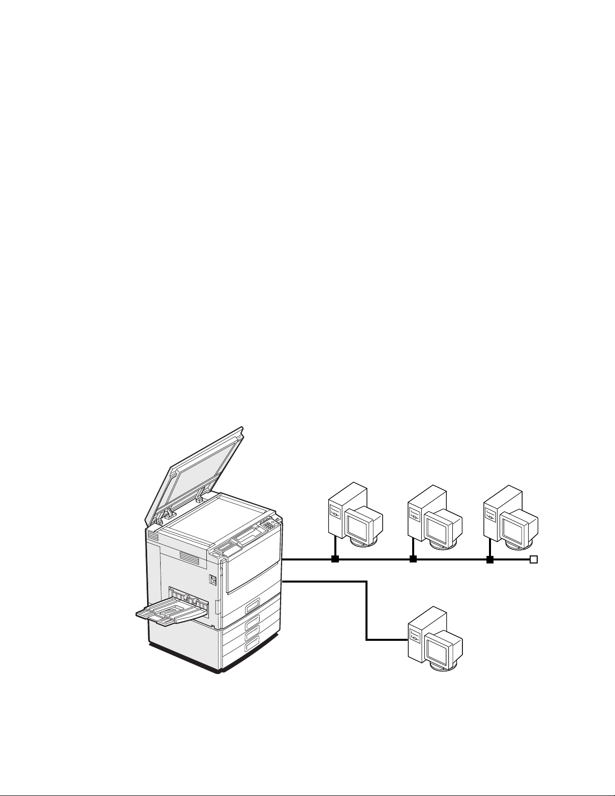
The E-300 is a high performance embedded color controller that provides computer
connectivity and highly efficient color printing capability to digital color copiers. It is
optimized for high-speed communications, processing, rasterization, and printing of
continuous tone color and monochrome (black and white) pages. Users can print from
networked Mac OS computers (version 7.6 or later), from networked PCs running
Microsoft Windows 3.1x, Windo ws NT, Windo ws 95, or Windo ws 98, and from UNIX
workstations. In addition, the E-300 parallel port can be used for printing directly from a
PC.
Features
As an integral part of the printing system, the E-300 enables users of Mac OS computers
and PCs to:
• Send images over AppleTalk, TCP/IP, and Novell networks, or through the parallel
port to print on a copier.
• Spool print jobs and select a printing priority for each job. Users can control spooled
print jobs sent to the E-300 with user software running on networked Mac OS
computers and PCs.
• Print files in color, grayscale, and black and white.
• Use PostScript fonts. The customer can download additional fonts, as needed.
Networked computers
IGURE
F
TRSH010E
E-300 printing system
1-1
PCCopier
1-1
Page 16
Introduction
1
• Built-in ColorWise
™
color management and NetWise
™
networking features
How the E-300 operates
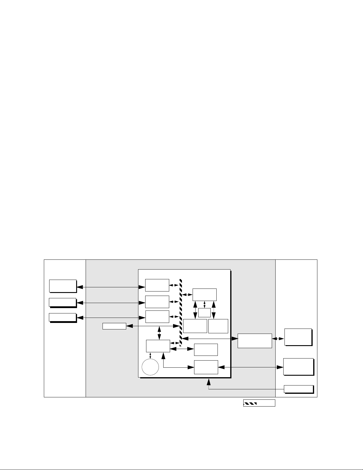
The E-300 provides efficient image processing and printing control. The E-300 board
includes a MIPS R5000 RISC (Reduced Instruction Set Computer) CPU with a built-in
floating point accelerator that runs the PostScript Interpreter. It interprets a page
description file to produce the image pattern in memory. The RipChips
control data management and other system functions, freeing up the CPU for efficient
image data processing.
Two high-speed DIMMs (dual in-line memory modules) on the E-300 board hold image
data during printing. The standard memory configuration is 160MB.
With the Fiery Scan TWAIN plug-in, the E-300 acquires RGB (red, green, blue) image
data from the copier, stor es it in memory, and transmits it to the computer that requested
the scan.
The PCI-based video interface board provides communication with the color engine.
Image data is sent via the video interface connector on the video interface board that
attaches to both the E-300 board and the copier I/F unit. Raster data is supplied to the
laser in the copier at full copier rated speeds.
™
on the board
External devices CopierE-300
E-300 Board
Networked
computers
PC
SCSI Device
HDD
FIGURE 1-2 E-300 functional diagram
Network
interface
Parallel
interface
interface
PCI-ISA
Battery
SCSI
RTC/
Memory &
Interpreter
DX
RIPChip
Flash
Super I/O
controller
Operation
Panel
interface
CPU
+5VDC, +12VDC
Print/Scan
Video interface
board
PCI Bus
Copier
Operation
Panel
Display
Power supply
1-2
Page 17

E-300 print options
1
E-300 print options
The E-300’s efficient PostScript capabilities allow customers to use a variety of
applications to create printed color or black and white pages of text and/or images. The
E-300 operates both over a network and directly over the parallel port. Since the E-300
has the ability to print an image while processing the next image (RIP-While-Print™), it
is capable of printing documents at full copier speeds.
Users can print documents directly from the applications in which they were created. In
addition, the E-300 offers an efficient way to print files that have been saved in
PostScript, EPS (Encapsulated PostScript), or PDF format. These files can be
downloaded directly to the E-300 using the Fiery Downloader, a r emote utility provided
with E-300.
Through the parallel port, customers can print documents directly from applications
running on a stand-alone or networked PC. PostScript files can also be printed to the
parallel port from Windows, including the MS-DOS window, without requiring the
applications in which the files were created.
1-3
Page 18

Introduction
1
User software
User software is provided on the User Software CD. The network administrator or the
user at the customer site is responsible for installing software onto computers that will use
the E-300 over the network. Installers for the printer files can also be downloaded with
the Installer WebTool. See the Getting Started manual for details.
The User Software CD includes:
Adobe PS Printer Driver Enables you to print Postscript files from Windows and
Mac OS computers; also supports all special E-300 print
features and PostScript 3 featur es. Windows NT 4.0 users
should use the Microsoft PostScript Printer Driver
provided with Windows NT 4.0.
PostScript Printer
Description files (PPDs)
PostScript 3 Screen Fonts
(Mac OS computers only)
Fiery Downloader Enables you to print PostScript, Encapsulated PostScript
Fiery Print Calibrator Enables the user to calibrate the E-300 from a remote
Fiery Spooler Enables the user to view the order and priority of print
Fiery Scan plug-in A TWAIN plug-in module for PhotoShop that enables the
Color management files ColorSync and ICM color management files that enable
These files are for use with the PostScript printer driver;
they allow the E-300 to appear in popular applications’
Print and Page Setup dialog boxes. The PPD files provide
information about the E-300 and your particular copier
model to the application and printer driver you are using
to print.
Screen fonts for the 136 PostScript printer fonts installed
(117 Adobe Type 1 and 19 TrueType). See the User G uide
for a complete list.
(EPS), and Portable Document Format (PDF) files
directly to the E-300 without using the application in
which they were created. Fiery Downloader also enables
the user to manage the printer fonts installed on the
E-300.
computer. Proper calibration keeps colors consistent.
jobs, customize printer settings for jobs, delete jobs, and
move jobs between queues. It can also be used to view job
accounting information.
user to scan images from the copier directly into
Photoshop.
users to maintain consistent color from the original
artwork to the display monitor to the printed output.
1-4
Page 19

E-300 print options
1
Color reference files Reference pages that can be printed to view the range of
colors available on the E-300. For the most predictable
color results, the user refers to these pages when defining
colors in applications.
Separation tables Allow the user to do RGB-to-CMYK conversions within
Photoshop that correspond to conversions performed by
color rendering dictionaries on the E-300.
Fiery WebTools
The E-300 can support Internet or intranet access with Fiery WebTools, which include
Status, Setup, WebSpooler, Installer, and WebLink. For more information on WebTools,
see the Administrator Guide and Getting Started.
1-5
Page 20

Page 21

Setting customer expectations
Chapter 2:
Installation
2
This chapter describes the process for installing the E-300 kit in the I/F unit. Topics
include setting customer expectations, unpacking the E-300, and performing the
installation.
Setting customer expectations
The customer should be informed of the following:
• Some nodes on the network may be unavailable during the installation.
• The network administrator needs to be available during the installation for network
connectivity.
Equipment downtime and impact on the network can be minimized if the network
administrator installs a network connector for the E-300 and confirms network
functionality with the connector in place before the date scheduled for the installation.
• The network administrator should have a networked computer available during the
installation. The appropriate software should already be installed. Documentation for
the networked computer and the network operating software should be available.
• The network administrator should install the user software shipped with the E-300 (a
package of user documentation is also included) onto networked Mac OS computers
and PCs that will print to the E-300.
NOTE: This guide covers E-300 hardware installation and service. It provides general
information on connecting the E-300 to the customer’s network. Network setup and
configuration information go beyond the scope of this guide. For network setup and
configuration information, the network administrator should refer to the Administrator
Guide.
2-1
Page 22
Installation
2
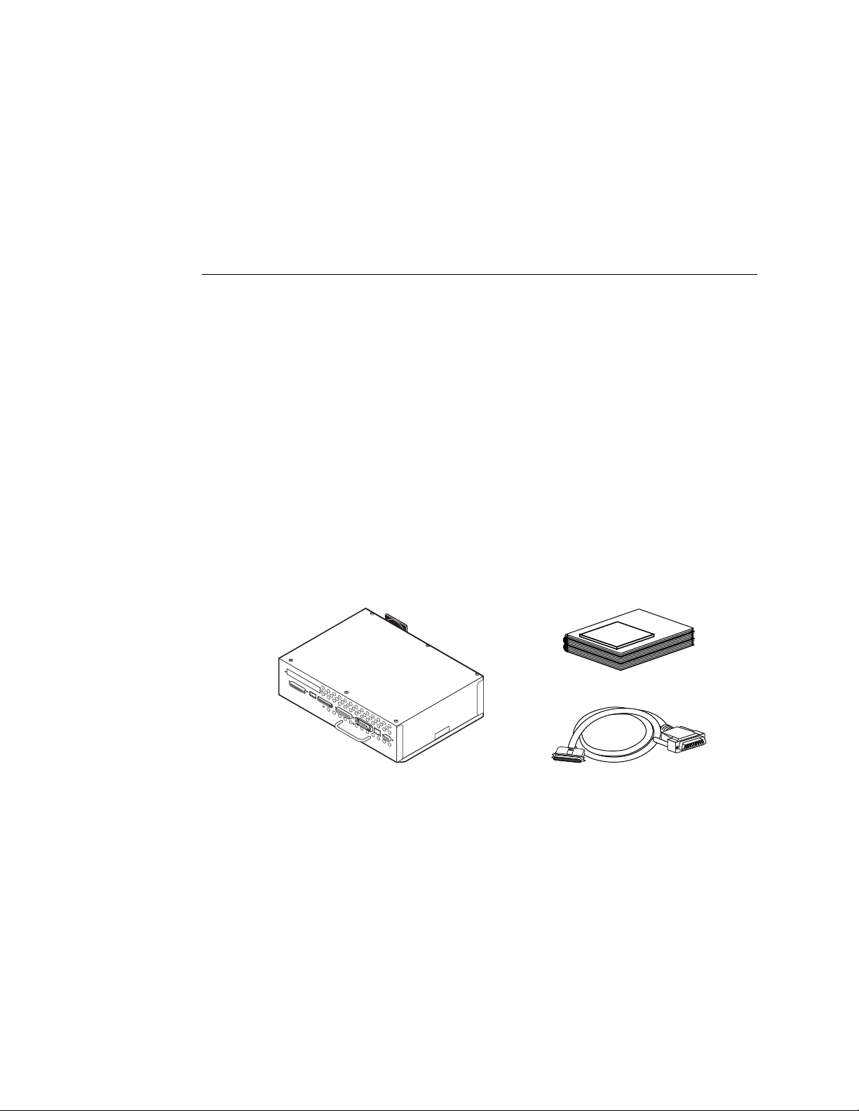
Unpacking the E-300
The E-300 is assembled and shipped from the factory in a box that includes items shown
in Figure 2-1.
TO UNPACK THE E-300
1. Open the shipping box and remove any packing materials.
2. Remove the contents of the shipping box and inspect them for visible damage.
If you notice shipping damage, have the shipping box ready to show the carrier if
necessary. Call the carrier immediately to report the damage and file a claim, then call
your authorized service/support center. The shipping box includes the following items:
• E-300
• Media package
• User Software CD (see page 1-4 for contents)
• User documentation (which includes but is not limited to Getting Started,
Administrator Guide, and User Guide)
• Kodak Color Separation and Gray Scale (small)
• Parallel IEEE 1284 A-C cable
Media Package
E-300
FIGURE 2-1 Contents of shipping box
NOTE: The E-300 requires the Controller Interface Type E kit to be installed.
3. Give the media package to the network administrator.
Let the network administrator know that in order to take full advantage of the E-300, the
user software must be installed on computers that will print to it.
Parallel Cable
2-2
Page 23

Preparing for installation
2
4. Give the Kodak Color Separation and Gray Scale (small) to a person at the customer site
who is responsible for calibration.
5. Remove any protectors that may be installed on connectors on the E-300.
If a jack is installed in the E-300 RJ-45 connector, grasp the jack with needlenose pliers
and pull it straight out of the connector.
Preparing for installation
Before installing the E-300, do the following:
❑ Test copier functionality.
Copy the copier test page before you install the E-300.
If the copied image indicates that the copier needs adjustment, inform the customer.
After getting approval, complete the copier service needed.
❑ Check the network.
Verify that the network is functioning before you attach the E-300.
• Ask the network administrator to print a document on a shared printer over the
network.
• Ask the network administrator to verify the computer and network requirements as
specified in Getting Started, one of the documents provided in the Media Package.
❑ Install the Controller Interface Type E kit.
See the Controller Interface Type E Installation Procedure for information.
Opening the copier
To gain access to the location inside the copier where the E-300 will be installed, you
need to shut down the copier and open the copier from the back.
Follow standard ESD (electrostatic discharge) precautions while handling components.
TO SHUT DOWN THE COPIER
1. Make sure the copier is not in use and power o ff the copier using the main po w er switch
on the side.
2. Disconnect the copier power cable from the wall outlet and any external cables.
2-3
Page 24
Installation
2
TO OPEN THE COPIER
1. Shut down the copier (see page 2-3).
2. Remove three of the screws that secure the I/F unit cover to the back of the copier.
3. While supporting the I/F unit cover, remove the fourth screw and remove the cover.
Set the I/F unit cover and screws aside so you can replace them later.
I/F unit cover
FIGURE 2-2 Removing the I/F unit cover
The area for the E-300 is now accessible. Make sure the Controller Interface Type E kit is
installed before attempting to install the E-300. See Controller Interface Type E Installation
Instructions for information.
Installing the E-300 in the copier
TO INSTALL THE E-300
1. If the customer has purchased additional options, such as the token ring interface boar d,
install these on the E-300 board.
See the documentation included in the specific option kit.
Copier
2-4
2. Observe the top and bottom slide guides inside the I/F unit and on the outside of the
E-300.
Make sure the slide guides inside the I/F unit have approximately a 30 degree lead-in
angle. If necessary, bend them to create the proper angle (see Figure 2-3 on page 2-5).
Page 25
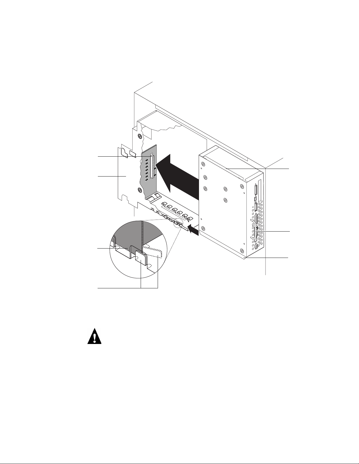
Connector in the I/F unit
I/F unit (cutaway view)
Installing the E-300 in the copier
2
E-300
top slide
guide
E-300 bottom slide guide
I/F unit slide guide
Handle
E-300
Bottom slide
guide
IGURE 2-3 Installing the E-300 in the I/F unit
F
3. Hold the E-300 by the handle and slide it into the I/F unit, using the slide guides on the
E-300 and inside the I/F unit to align the E-300.
Make sure the E-300 is aligned inside both the top and bottom slide guides. If
misaligned, the copier interface connector on the video interface board can be damaged.
2-5
Page 26
Copier interface connector
Installation
2
4. Push the E-300 until the connector in the I/F unit and the copier interface connector on
the video interface board are securely connected.
I/F unit
F
IGURE 2-4 Copier interface connector
5. Use the four screws provided in kit to attach the E-300 to the I/F unit.
E-300
IGURE 2-5 Attaching the E-300 to the I/F unit
F
2-6
Page 27

Initial startup
2
Reassembling the copier
It is recommended that you fully reassemble the copier before you apply power to verify
E-300 functionality.
TO REASSEMBLE THE COPIER
1. Replace the I/F unit cover with the four screws you removed earlier (see Figure 2-2 on
page 2-4).
2. Connect the main power cable to the wall outlet and to the copier.
Initial startup
1. Power on the copier.
2. If the Select Language screen is displayed, display the language of your choice , pr ess the
Enter key, then wait for the Setup screen to be displayed.
The first time the copier is powered on following installation of the E-300 (or
reinstallation of system software), you are prompted to select the language to be used for
both the E-300 Operation Panel and special E-300 pages, such as the Configuration
page. Use the up and down arrows to cycle through the languages available.
If you select a different language, the prompt to reboot appears in the language you
selected. Press the Enter key to reboot then wait for the Setup screen to be displayed. To
change the language again, you must reinstall system software.
3. If the Setup screen is displayed, select Server, Printer, Network, and Exit Setup.
Before you can exit Setup, you must first enter S erver Setup , Network Setup, and Printer
Setup and save changes. Enter each Setup, press the Cancel key, and when prompted to
save changes, select Yes.
It is the network administrator’s responsibility to configure Setup according to the
network and user environment. At this stage, default settings in Setup are adequate
although they may not be optimal for the user’s environment. Refer the network
administrator to the Administrator Guide for Setup information.
4. Allow the system to proceed to the Info screen to confirm that the E-300 is operating
normally. Scroll down to display E-300 status.
Info
Ready
Server Name
Ready
Ready
1884 MB X.X
Once the E-300 reaches the Info screen, you are ready to print a Test Page and then
connect the E-300 to the network (see “Printing a Test Page” on page 2-10).
2-7
Page 28
Installation
2
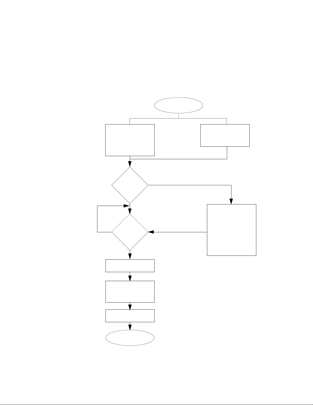
E-300 startup navigation
Use the diagrams on the following pages to navigate the E-300 system on startup. The
startup sequence varies for initial startup and standard startup.
Power on the copier
using the power switch
Press Cancel
“PLEASE WAIT” flashes
during E-300 start-up
diagnostics. If a test
fails, see
“Troubleshooting”.
Do you want
to go to
Setup?
Press No or do
nothing
Select a
language
Press Enter
The Setup screen is
displayed.
Copier performs its
start-up sequence and
beeps 3 times when
done.
Press Yes
The Startup screen is
displayed so you can
access the following:
-Run Setup
-Start System
-Reboot System
-Install Software
-Format Disk
-Upgrade Flash
-Flash Info
2-8
Save default settings in
Server, Network, and
Printer Setup then Exit
Setup.
System reboots
Loading System...is
displayed.
The Info screen is
displayed.
FIGURE 2-6 Initial startup sequence
Page 29
Initial startup
2
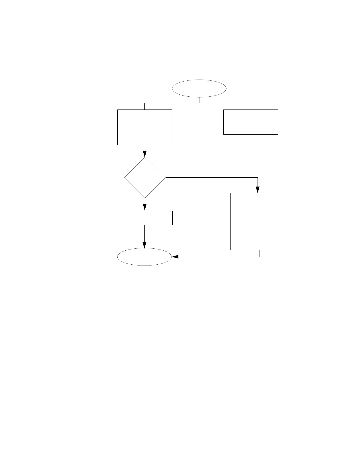
Power on the copier
using the power switch
“PLEASE WAIT” flashes
during E-300 start-up
diagnostics. If a test
fails, see
“Troubleshooting”
Do you want
to go to
Setup?
Press No or do
nothing
Loading System...is
displayed.
The Info screen is
displayed.
Copier performs its
start-up sequence and
beeps 3 times when
done.
Press Yes
The Startup screen is
displayed so you can
access the following:
-Run Setup
-Start System
-Reboot System
-Install Software
-Format Disk
-Upgrade Flash
-Flash Info
Exit the Startup screen (the
system may reboot before
displaying the Info screen)
IGURE 2-7 Standard startup sequence
F
2-9
Page 30

Installation
2
Printing a Test Page
Before connecting the E-300 to the network, print a Test Page to verify that the E-300 is
embedded properly in the copier and working. The Test Page is a file that resides on the
E-300 hard disk drive.
TO PRINT A TEST PAGE
1. If the copier is powered off, power it on.
2. Wait while the E-300 and the copier perform their startup sequences.
The E-300 displays the Info screen when ready. The copier beeps 3 times when ready.
Scroll down to display E-300 status.
Info
Ready
Server Name
Ready
Ready
1884 MB X.X
3. Press the Menu key to access the Functions screen.
4. Select Print Pages.
Functions
Print Pages
Suspend Print
Resume Print
Run Diagnostics
Reboot Server
5. Select Test Page.
6. Examine the Test Page.
Success in printing the Test Page confirms that the E-300 is functional and connected
properly to the copier. Poor quality may indicate a need to service or adjust the copier,
not the E-300.
Select
2-10
Page 31

Printing the Configuration page
2
Printing the Configuration page
The Configuration page can be helpful during installation, setup, and service. After
installation of the E-300 and before any default settings are changed, you can obtain a
record of the defaults by printing the Configuration page.
After the physical connection to the network is made, the network administrator can
customize Setup options according to the network and user environment. Using the
Configuration page as a guide can help speed up this process. For more information, see
the Administrator Guide.
Before you perform any service procedure, you should print the E-300 Configuration
page, if possible, so that you are prepared to return the settings to their former
configuration, if necessary.
TO PRINT THE CONFIGURATION PAGE
1. If the copier is powered off, power it on.
2. Wait while the E-300 and the copier perform their startup sequences.
The E-300 displays the Info screen when ready. The copier beeps 3 times when ready.
Scroll down to display E-300 status.
Info
Ready
Server Name
Ready
Ready
1884 MB X.X
3. Press the Menu key to access the Functions screen.
4. Select Print Pages.
Functions
Print Pages
Suspend Print
Resume Print
Run Diagnostics
Reboot Server
5. Select Configuration.
6. Save the Configuration page for future reference.
Select
2-11
Page 32

Installation
2
Connecting the E-300 to the network
The E-300 board provides connectivity to an Ethernet network, either thinnet, thicknet,
or twisted pair.
Token Ring compatibility is available using the optional Token Ring kit (see the
documentation included with that kit for more information).
2-12
Page 33

Printing the Configuration page
2
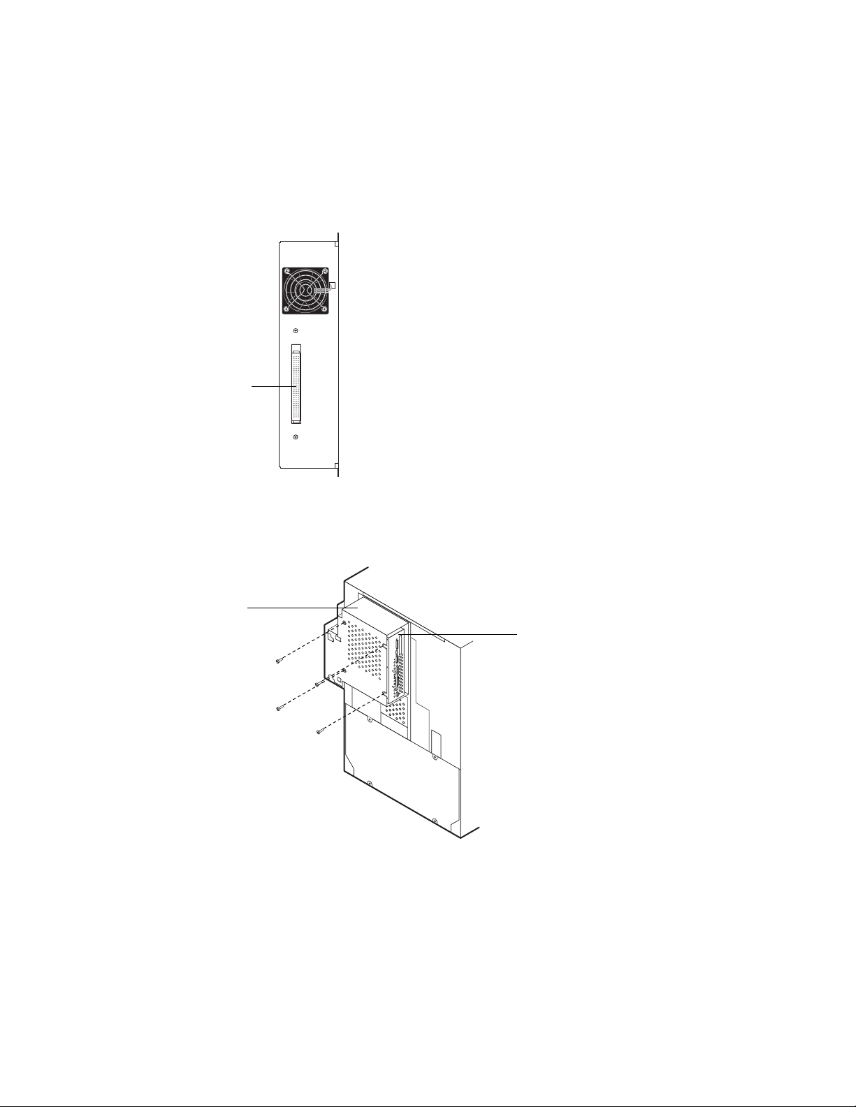
Ethernet network connection
The E-300 board has two external Ethernet network connectors:
• A 10BaseT/100BaseT RJ-45 connector for attaching a Category 3 or Category 5
unshielded twisted pair (UTP) network cable (see Figure 2-8). Category 5 is required
for 100BaseT.
• A 15-pin D AUI (Attachment Unit Interface) connector for attaching one of the
following:
• An Ethernet transceiver for 10Base2 (thinnet)
• A thick Ethernet cable for 10Base5 (thicknet)
Only one Ethernet connection can be made to the E-300 board at a time. Use either the
AUI connector or the RJ-45 connector, never both.
FIGURE 2-8 E-300 network connectors
AUI connector for thinnet
or thicknet
10BaseT/100BaseT connector
for twisted pair Ethernet
2-13
Page 34

Installation
2
TO CONNECT A THINNET OR THICKNET CABLE TO THE E-300
A thinnet (coaxial 10Base2 Ethernet cable) connection requires an external transceiver
attached directly to the AUI connector on the E-300.
A thicknet (coaxial 10Base5 Ethernet cable) connection requires an external transceiver
with an AUI drop cable connected to the AUI connector on the E-300.
1. Power off the E-300 before connecting it to any network device.
2. If installed, remove the dust cover from the AUI connector.
3. With the AUI slide latch in the open position, connect the network cable to the AUI
connector on the E-300. Slide the latch to lock the connector in place.
• To connect a 10Base2 thinnet cable to the E-300, an Ethernet external transceiver
must be installed on the E-300 AUI connector . The thinnet cable then connects to the
BNC connector on the external transceiver.
If the transceiver has an SQE switch, make sure the switch is set to OFF.
• To connect a 10Base5 thicknet cable to the E-300, connect the AUI drop cable directly
to the AUI connector on the E-300.
4. Configure Setup options.
It is the network administrator’s responsibility to configure Setup according to the
network and user environment. Default settings in Setup are adequate although they may
not be optimal for the user’s environment. Refer the network administrator to the
Administrator Guide for Setup information.
5. After configuring Setup options, verify the network connection.
Once the network connection has been made and the E-300 has the correct Setup
configuration and is Ready, the E-300 should be available on the network.
If necessary, the network administrator should perform any additional network Setup,
verify the network connection, verify that the E-300 appears on the list of printers, and
print a few test documents from a networked computer that will use the E-300. (See the
Administrator Guide for more information.)
2-14
Page 35

Printing the Configuration page
2
TO CONNECT A TWISTED PAIR CABLE TO THE E-300
A Category 5 unshielded twisted pair (UTP) network cable must be used for 100BaseT.
It connects to the RJ-45 connector on the E-300.
1. Power off the E-300 before connecting the E-300 to any network device.
2. If installed, remove the dust cover from inside the RJ-45 connector.
Grasp the jack with needlenose pliers and pull it straight out of the connector.
3. Connect the network cable to the RJ-45 connector on the E-300.
4. Configure Setup options.
It is the network administrator’s responsibility to configure Setup according to the
network and user environment. Default settings in Setup are adequate although they may
not be optimal for the user’s environment. Refer the network administrator to the
Administrator Guide for Setup information.
5. After configuring Setup options, verify the network connection.
Once the network connection has been made and the E-300 has the correct Setup
configuration and is Ready, the E-300 should be available on the network.
The network administrator should perform any additional network Setup, verify the
network connection, verify that the E-300 appears in the list of printers, and print a few
test documents from a networked computer that will use the E-300. (See the
Administrator Guide for more information.)
2-15
Page 36

Installation
2
Connecting a PC to the parallel port
On the E-300, the parallel port connector (female 36-pin mini-Centronics) provides a
high-speed interface port for connecting directly to the parallel port of a PC. The parallel
cable is included in the E-300 kit.
The E-300 can be connected to the network and to a parallel port device at the same
time.
FIGURE 2-9 E-300 parallel port connector
Parallel port connector
2-16
Page 37

Printing the Configuration page
2
TO CONNECT THE E-300 TO A PC
NOTE: If the PC is for installing system software, make sure it meets the minimum
requirements specified in “E-300 system software” on page 4-26.
1. Power off the copier before connecting the E-300 to a PC.
2. Power off the PC.
3. Connect the IEEE 1284-C connector of a parallel (Centronics) cable to the 36-pin miniCentronics connector on the E-300 board.
4. If installed, remove the dust cover from the parallel connector.
5. Connect the other end of the parallel cable to the parallel port of the PC.
If there is more than one parallel port connector on the back of the PC, ask the network
administrator to indicate the preferred parallel port to use for the copier.
6. Power on the PC and the copier.
7. Configure Setup options.
It is the network administrator’s responsibility to configure Setup according to the
network and user environment. Default settings in Setup are adequate although they may
not be optimal for the user’s environment. Refer the network administrator to the
Administrator Guide for Setup information.
8. After configuring Setup options, verify the parallel port connection.
Once the parallel port connection has been made and the E-300 has the correct Setup
configuration and is Ready, the network administrator should print a few test documents
from the PC connected to the copier. See the Administrator Guide for more information.
2-17
Page 38

Page 39

Overview
Chapter 3:
Using the E-300
Operation Panel
3
This section describes the E-300 functions on the E-300 Operation Panel. The E-300
Operation Panel is an area dedicated to E-300 functions. It is located on the top left side
of the copier Operation Panel. The keys on the E-300 Operation Panel allow you to
access and monitor different features of the E-300. This guide does not attempt to
describe all functions of the Operation Panel, only those functions that pertain to the
E-300. For information on installing the E-300 Operation Panel, see the Controller
Interface Type E Installation Procedure.
Overview
Current status and Setup information are displayed on the E-300 Operation Panel. Print
activity can be monitored in the display window and specific E-300 functions (such as
printing a Test Page and installing or updating system software) are controlled using the
keys on the E-300 Operation Panel. Three LEDs assist in providing status information.
Printing/processing LEDPrinter/Scanner LED and keyDisplay Window
Error LED
Arrow keysCancel key Enter key Menu key
Printer/
Scanner
Cancel Enter # Menu
FIGURE 3-1 E-300 Operation Panel (International and U.S. models)
3-1
Page 40

Using the E-300 Operation Panel
3
Keys
Once the E-300 board is installed in the copier, use the E-300 keys on the Operation
Panel to perform the following functions:
Key
(International)
Key
(U.S.)
Menu
Enter
Cancel
Printer/
Scanner
Description
From the Info screen, display the Functions screen when idle and the run-time
screen when a job is in process.
Select the currently displayed menu item and proceed to the next screen. Cancel a
job from the printing or processing screen.
Scroll down the screen to display menu items or part of a text message. After the
bottom of the screen is reached, the top of the screen is displayed.
Scroll up the screen to display the previous menu item or part of a text message.
When the top of the screen is reached, the bottom of the screen is displayed.
Backspace the cursor to the text-entry position to the left. In a text field, it deletes
the character to the left.
Advance the cursor to the text-entry position to the right.
In the menus, return to previous level.
Not used for E-300 functions. See other service technician documentation.
3-2
Page 41

Activity indicators
3
Activity indicators
Once the E-300 board is installed in the copier, the red and green activity lights on the
E-300 Operation Panel turn on and stay solid or flash on and off to indicate the
following:
Activity
indicator
(International)
Activity
indicator
(U.S.)
Printer/
Scanner
Description
• Flashing red—An error prevents the E-300 from processing a job (see the User
Guide for more information).
• Solid red (more than 30 seconds)—A communication error has occurred
between the E-300 and the copier.
• Flashing green—The E-300 is processing a job or communicating with a
remote computer.
• Solid green—The E-300 is using the copier to print or scan a job.
Screens
When the copier is idle, E-300 status information and functions available from the
E-300 Operation Panel. You can monitor print activity, control E-300 functions (such as
printing a Test Page and installing or updating system software), and access the E-300
Setup menus.
When a job is sent to the copier, the E-300 Operation Panel cycles through the RIP and
Print screens, and then displays the Info screen. If an error occurs, the Alert screen is
displayed with a message describing the error.
A Startup screen is also available It is made available when the system is powered on or
when you reboot the system. It has options for setting up the printer, rebooting the
E-300, formatting the hard disk drive, installing system software, and upgrading the
flash.
These screens offer the following features:
• Info status screen—The first line of this screen displays the printer’s name on the
network. Scrolling down displays the status of the E-300, the amount of disk space
available on the hard disk drive, and the current system software version. Normally, if
no jobs are currently being processed or printed, the Info screen displays Ready (a job
may be between processing and printing). The Info screen is the default screen. Press
the Menu key to display the Functions screen.
3-3
Page 42

Using the E-300 Operation Panel
3
Info
Ready
Server Name
Ready
Ready
1884 MB X.X
• RIP status screen—Appears when a job is being processed. Displays the name of the
file, the name of the user who sent the job, the status, and the amount of the job in
kilobytes that has been processed so far . To cancel the job, display Cancel J ob and pr ess
the Enter key. Press the Cancel key to display the Functions screen.
RIP
Cancel Job
doc.eps
Jack D.
Busy ####K
• Print status screen—Appears when a job is being printed. Displays the name of the
user who sent the job, the number of copies printed so far, and the number of copies
requested. To cancel the job, display Cancel Job and press the Enter key. Press the
Cancel key to display the Functions screen.
Print
Cancel Job
Jane D.
Copies: 1/100
R4
• Alert screen—Displays a message if an error or other Alert condition arises. Pressing
the down arrow key may be necessary to view the entire error message. If other screens
are being accessed, the Alert screen is redisplayed frequently until the condition is
resolved. Press the Cancel key to display the Functions screen.
Alert
Warming up
R4
• Functions screen—Gives you access to administrative functions not normally
performed from a remote workstation (see “Functions screen” below for information
on the available functions). Press the Cancel key to display the Info screen.
Functions
Print Pages
Suspend Print
Resume Print
Run Diagnostics
Reboot Server
3-4
Page 43

Screens
3
Functions screen
The Functions screen allows you to perform a variety of administrative functions that do
not affect print jobs of other users. Use the up and down arrow keys to scroll thr ough the
menu items. Press the Enter key to select the menu item displayed. Press the Cancel key
or do nothing to return to the Info screen. The following options are available from the
Functions screen:
Print Pages—Enables you to print special pages from the copier:
• Test Page—Prints the Test P age resident on the E-300 har d disk drive. The T est
Page confirms that the E-300 is properly installed in the copier and allows you
to view information about color and grayscale to troubleshoot E-300 functions.
Test Page information includes but may not be limited to: Server name, Printer
name, Calibration, Measurements, Target, Date & Time, CMYK Simulation,
RGB Source, Rendering Style, Color Mode. For more information see the User
Guide and the Administrator Guide.
Configuration—Prints the current device configuration, including information
•
about all current Setup settings, calibration profile, and the Ethernet address of
the E-300 board.
• Job Log—Prints the log of the last 55 jobs. F or more information about the job
log, see the User Guide.
• Menu Map—Prints the E-300 Menu Map, useful when navigating through the
different E-300 Setup screens.
• Color Charts—Prints the color reference charts, including swatches of the RGB,
CMY, and Pantone colors available from the E-300.
• Font List—Prints a list of all the fonts resident on the E-300 hard disk drive.
Suspend Printing— This option interrupts the current print job so you can use the copier
to make copies. If it has not finished processing, the RIP will continue but the job will
not print. You can then select Resume Printing.
Resume Printing—Resumes printing after interrupting the print job in order to make
copies.
Run Diagnostics—Select this option to access:
• Video Diagnostics— Runs diagnostics on the E-300 video interface (see “Video
interface diagnostics” on page 5-10).
Reboot Server—Shuts down all printing activity properly and then restarts the E-300.
Access to E-300 Setup options are made available at this time.
3-5
Page 44

Using the E-300 Operation Panel
3
Startup screen
• The Startup screen is made available when you reboot the system from the Functions
screen or when you power on the copier. For startup navigation, see page 2-8. The
following options are available from the Startup screen.
Start Up
Ready
Run Setup
Ready
Start System
Start Up
Reboot System
Start Up
Install Software
Start Up
Format Disk
Start Up
Upgrade Flash
Flash Info
• Run Setup—allows you to access E-300 Setup options in order to configure the
network and printing environment. Typically it is the network administrator’s
responsibility to configure Setup according to the network and user environment.
Setup is required the first time the copier is powered on after new E-300 system
software is installed. You must enter and save changes to Server, Network, and Printer
Setup after installing system software.
Setup options include: Server, Network, Printer, PS Setup, Color Setup, Job Log
Setup, Calibration, Change Password, and Clear Server. See the Administrator Guide
for detailed information on Setup.
NOTE: Make sure the network administrator is available to customize Setup options
according to the network and user environment.
• Start System—Exits the Start Up screen and displays the Info screen.
• Reboot System—Shuts down all E-300 activity in the correct manner and restarts the
E-300. Press the Enter key to reboot the E-300. Once the server reboots you can access
Setup options.
• Install Software—Allows you to install E-300 system software from the CD to the
hard disk drive installed on the E-300.
• Format Disk—Allows you to format the hard disk drive installed on the E-300 so you
can install system software. You need to do a standard format of the HDD before
installing system software. Options include Standard, Full, and Full & Verify.
• Upgrade Flash—If a Boot ROM file is pro vided, allo ws you to upgrade the boot ROM
installed on the E-300.
Flash Info—Provides version information about the Boot ROM installed on the E-300.
3-6
Page 45

Overview
Chapter 4:
Service
Procedures
4
Generally, the E-300 does not require regular maintenance. Use the procedures in this
chapter to inspect, remove, reseat, or replace major hardware components and also to
install system software.
Overview
This chapter includes information on the following:
• Cable connections (page 4-6)
• E-300 board (page 4-9)
• E-300 board components
• Video interface board (page 4-13)
• DIMMs (page 4-16)
• Battery (page 4-18)
• CPU fan (page 4-19)
• Exhaust fan (page 4-20)
• Hard disk drive (page 4-21)
• System software (page 4-26)
For information on how to remove and replace the I/F unit that encloses the E-300, see
the Controller Interface Type E Installation Procedure.
See Figure 4-1 on page 4-2 for an overview of E-300 board components. Replacement
parts are available from your authorized service representative.
When performing the procedures described in this chapter , see “P recautions ” on page xiii
and “Tools you will need” on page xiv.
The E-300 system software is installed on the hard disk drive at the factory. You will need
to re-install system software if you:
• Replace the hard disk drive
• Replace the motherboard
• Upgrade to a more recent version of the system software
4-1
Page 46

Service Procedures
4
Key
1. Pan cover
2. Video interface board
3. Video interface board bracket
4. CPU fan
5. DIMMs
1
2
3
4
7
5
6. Power cable
7. Battery
8. E-300 board
9. HDD EIDE cable
10. HDD
11. Exhaust Fan
12. Pan
8
9
10
11
12
6
4-2
FIGURE 4-1 Exploded view of E-300
Page 47

Accessing the E-300
4
Accessing the E-300
Always use the following procedures when accessing the E-300. Make sure you attach an
ESD grounding wrist strap and follow standard ESD (electrostatic discharge) precautions
before following this procedure.
TO SHUT DOWN THE COPIER
1. Make sure that the E-300 Operation Panel is idle.
When Printing or Ripping appears on the E-300 Operation P anel, the E-300 is currently
processing. Ready appears in the Info screen when the E-300 has finished processing and
is idle.
Info
Ready
Server Name
Ready
Ready
1884 MB X.X
2. Power off the copier using the power switch on the side of the copier.
3. Unplug the power cable from the wall outlet.
4-3
Page 48

Service Procedures
4
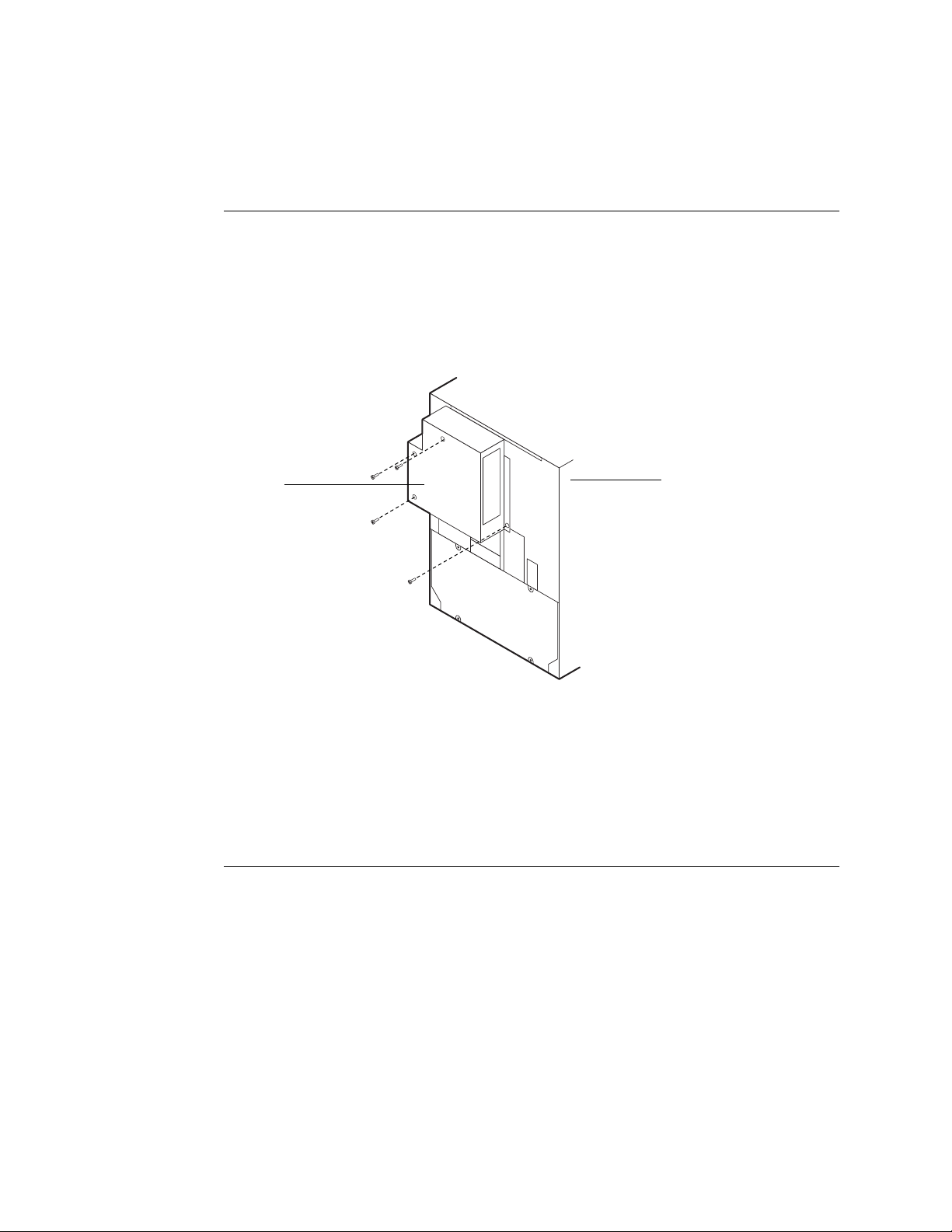
TO ACCESS THE E-300
1. Shut down the copier (see page 4-3).
2. Remove three of the screws that secure the I/F unit cover to the back of the copier.
I/F unit
I/F unit cover
E-300 handle
F
IGURE 4-2 Accessing the E-300
3. While supporting the I/F unit cover, remove the fourth screw and remove the cover.
Set the I/F unit cover and screws aside so you can replace them later.
4. Remove the four screws that secure the I/F unit to the E-300.
Set the screws aside so you can replace them later.
5. Use the handle to pull out the E-300 from the I/F unit.
Set the E-300 on a stable static-free surface.
4-4
Page 49

4
Pan cover
Screw
Accessing the E-300
6. Remove the six screws that secure the pan cover. Lift off the pan cover and set it aside.
F
IGURE 4-3 Removing the pan cover
The E-300 components are now accessible.
4-5
Page 50

Service Procedures
4
Checking E-300 internal connections
The most common causes of hardware problems are faulty and loose connections.Before
you conclude that any board or component has failed, remove, inspect, and reseat all
appropriate connections, and then verify that the problem still occurs.
TO CHECK BOARD AND CABLE CONNECTIONS
1. Before you touch any parts inside the E-300, attach a grounding wrist strap. Touching
the pan also discharges static electricity.
2. Place the E-300 so the internal components of the E-300 are facing up.
3. Make sure the DIMMs are properly installed (see “To replace a DIMM” on page 4-17 for
the proper procedure).
4. Make sure the battery is properly installed (see “To replace the battery” on page 4-18).
5. Make sure the video interface board is properly installed (see “To replace the video
interface board” on page 4-15).
6. Inspect the copier interface connector on the video interface board.
If any pins are pushed in or bent, gently fix them with a pair of small needlenose pliers.
7. Inspect the HDD EIDE cable to make sure it is intact.
Faulty ribbon cables are easily overlooked. Check the contact point between the cable
and the connector to ensure that they have not separated. If a ribbon cable is suspect,
substitute it with a tested cable.
8. Check the fan cables of the exhaust fan and the CPU fan.
Make sure the cables are intact. Also, check airflow direction. When the fans ar e installed
properly:
• An arrow on the exhaust fan points away from the E-300
• An arrow on the CPU fan points to the CPU
9. Make sure the power cable is intact and pr operly connected to the E-300 board, the HDD,
and the video interface board.
The cable has 3 connectors. The 4-wire end connector plugs into the HDD. The 6-wire
end connector plugs into the E-300 board. The middle connector plugs into the video
interface board. See Figure 4-4 on page 4-7.
10. Make sure board jumpers have the correct jumper configuration.
4-6
Page 51

Checking E-300 internal connections
4
One jumper is installed on 2-pin jumper area J25. It allows the flash boot ROM to be
upgraded in the field. The other 2-pin jumper areas J14, J15, J21, and J23 have no
jumpers installed and are for factory use only. Each is located near a mounting hole. See
page 4-9.
Power cable— middle connector
5
Copier interface
connector
HDD EIDE cable
Power cable
4-wire segment
CPU fan cable
Exhaust fan cable
Cable key From To
1. HDD EIDE cable
2. Power cable—4-wire segment
3. CPU fan cable
4. Exhaust fan cable
5. Power cable—middle connector
NOTE: J18 and J28 on the E-300 board are interchangeable.
1
2
3
4
EIDE connector on HDD EIDE connector on E-300 board (J3)
Power connector on HDD Power connector on video interface board (J8)
CPU fan Fan connector on the E-300 board (J28)
Exhaust fan Fan connector on the E-300 board (J18)
Power connector
on video interface board (J8)
Video interface
connector
Video interface
board
Power connector on the E-300 boar d (J16) and
Power connector on HDD
FIGURE 4-4 E-300 cable connections
4-7
Page 52

Service Procedures
4
Replacing parts of the E-300
The E-300 board has a 200MHz R5000 CPU. The E-300 board provides the Ethernet
networking interface, controls hard disk drive functions, and handles the communication
between the E-300 and external devices. With its video interface board it controls the
video image data transferred to and from the copier. In the standard configuration, two
DIMM sockets hold 160MB of memory (see Figure 4-8 on page 4-16 and also
“DIMMs” on page 4-16).
When replacing any of its components, make sure to protect the E-300 board from
excessive bending and flexing. When possible, remove the E-300 boar d from the pan and
remove the standoffs from the board’s corners and lay the E-300 board flat before
servicing.
Following are instructions for accessing, removing, and replacing the following parts of
the E-300:
• E-300 board
• E-300 board components including
• Video interface board
• DIMMs
• Battery
• CPU fan
• Exhaust fan attached to the pan
• HDD
Make sure you attach an ESD grounding wrist strap and follow standard ESD
(electrostatic discharge) precautions before following this procedure.
4-8
Page 53

Replacing parts of the E-300
4
E-300 board
The E-300 board is installed in the pan on four standoffs. This section includes
instructions for replacing the E-300 board and E-300 board components.
5 6321 4 7
MH
MH
MH
12
13
11
8
9
17
10
19 20
18
Key
1. Not used (J7) 12. Exhaust fan cable connector (J18)
2. 10/100BaseT Ethernet port (J6) 13. CPU fan cable connector (J28)
3. 10Base2/10Base5 Ethernet port (J11) 14. Battery (BT1)
4. Not used (J12) 15. HDD EIDE cable connector (J3)
5. Parallel port (J2) 16. Not used (J4)
6. Not used (U1) 17. CPU, heatsink, and CPU fan (U15)
7. SCSI port (J27) 18. Power cable connector (J16)
8. DIMM sockets (J26, J17, J9, J10) 19. Not used (J13)
9. Video interface connector (J24) 20. Not used (J19)
10. J25 (2 pins) Jumper in allows Flash upgrade
11. Option board connector (J1) MH Mounting holes (4)
16
14
15
MH
FIGURE 4-5 E-300 board layout
4-9
Page 54

Service Procedures
4
TO REMOVE THE E-300 BOARD
1. Print the Configuration page from the Functions menu.
If you are replacing the E-300 board, you will need to reinstall system software after the
new E-300 board is installed. Setup settings are reset to the default configuration when
you reinstall system software. The Configuration page gives you current Setup
information.
2. Print the Font List from the Functions menu.
The Font List details what fonts are installed on the E-300 HDD. Along with the fonts
that are provided on the System Software CD, the customer may have installed
additional fonts that will be deleted when you reinstall system software.
3. Shut down the copier and access the E-300 as described on page 4-3.
4. If an option board is installed in E-300 board connector J1, remove it.
5. Remove the video interface board fr om E-300 boar d connector J24 (see “Video interf ace
board” on page 4-13).
6. Remove the exhaust fan cable from E-300 board connector J18 (see “Exhaust fan” on
page 4-20).
7. Remove the HDD EIDE cable from E-300 board connector J3.
Using a ribbon cable connector extractor is recommended.
8. Remove and set aside the screws (and washers, if present), stando ff s, and A UI latch that
attach the external connectors to the pan (see Figure 4-6).
SCSI port screws
Parallel port screws
25-pin D (not used) standoffs
AUI port screws and latch
9-pin D (not used) standoffs
4-10
F
IGURE 4-6 External connector hardware on E-300 pan
Page 55

Replacing parts of the E-300
4
Make sure to keep each set of screws together.
Use a 3/16" hex nut driver to remov e the standoffs on the 9-pin D connector and the 25-
pin D connector.
Use a #1 Phillips screwdriver for the SCSI connector and the parallel connector.
Use a small flat-blade screwdriver to remove the screws from the AUI slide latch. Note
the orientation of the AUI latch so you can reinstall it correctly later.
9. Remove and set aside the four screws that secure the E-300 board to the standoffs.
10. Remove the power cable from E-300 board connector J16.
Lift the E-300 board off the standoffs and carefully tilt it out of the pan to access the
power cable.
11. Completely remove the E-300 board from the E-300 pan. Place the board on a stable
antistatic work surface or into an antistatic bag.
Make sure the connectors clear the pan as you remove the board.
4-11
Page 56

Service Procedures
4
TO REPLACE THE E-300 BOARD
NOTE: To make sure the copier interface connector (on the video interface board) is
properly aligned, make sure not to tighten screws until all components are in place.
1. Connect the power cable to E-300 board connector J16.
Carefully tilt the E-300 board into the pan to access the power cable.
2. Place the E-300 board inside the pan so that the external connectors fit into the pan
cutouts.
3. Align the E-300 board with the pan standoffs and then replace the f our mounting screws
into the pan standoffs.
4. Insert the screws (and washers, if present), standoffs, and AUI latch that attach the
external connectors to the pan (see Figure 4-6 on page 4-10).
Use a 3/16" hex nut driver to install the standoffs on the 9-pin D connector and the 25pin D connector. Use a #1 Phillips screwdriver for the SCSI connector and the parallel
connector.
For the AUI latch, use a small flat-blade screwdriv er to install the screws. Orient the AUI
latch according to Figure 4-6 on page 4-10. Install one screw almost completely , place the
latch over the connector, then install the second screw.
5. Connect the HDD EIDE cable to E-300 board connector J3.
6. Connect the exhaust fan cable to E-300 board connector J18.
7. Install the video interface board in E-300 board connector J24 (see “Video interface
board” on page 4-13).
8. Install any option board removed from E-300 board connector J1.
9. Reassemble the copier and verify functionality as described in “Restoring E-300
functionality after service” on page 4-24.
10. If you replaced the E-300 board with a new one, install system software (see
page 4-26). If a startup error occurs when you power on the copier, check E-300
connections. If a startup error still occurs, call your authorized service/support center.
4-12
Page 57

Replacing parts of the E-300
4
Video interface board
The video interface board provides the interface between the E-300 and the copier. It
connects to video interface connector J24 on the E-300 board and to the connector in
the I/F unit (see Figure 4-7 and Figure 2-3 on page 2-5).
J4 connects to E-300
board
Power connector J8 connects
to power cable
Bracket mounting holeBracket mounting hole
Copier interface connector J6 connects to I/F unit
FIGURE 4-7 Video interface board layout
4-13
Page 58

Service Procedures
4
TO REMOVE THE VIDEO INTERFACE BOARD
1. Shut down the copier and access the E-300 as described on page 4-3.
2. Remove the power cable from video interface board connector J8.
3. Remove and set aside the two screws that attach the video interface board br acket to the
pan.
4. Gently remove the video interface board (with attached bracket) from E-300 board
connector J24 and lift it out of the pan.
Grasp the board at the sides. Gently pull the board straight out of the connector.
5. Place the board in an anti-static bag.
4-14
Page 59

Replacing parts of the E-300
4
TO REPLACE THE VIDEO INTERFACE BOARD
NOTE: To make sure the copier interface connector is properly aligned, make sure not to
tighten screws until all components of the E-300 are in place.
1. Remove the board with bracket attached from the anti-static bag.
2. On the E-300 board, make sure that the power cable 6-wire segment is flat.
Make sure the cable wires are uncrossed in order to prevent excessive tension on the
underside of the video interface board. Tension on the video interface board could cause
misalignment of the copier interface connector.
3. Insert the video interface board into E-300 board connector J24.
Grasp the board at the sides. Gently push the board straight into the connector. Check
the visible portion of the gold fingers of the connector on the video interface board to
determine if the connection is aligned properly and secure.
4. Make sure that the bracket is flat against the inside of the pan and the two screw holes
by the bracket cutout are aligned with the scr e w holes in the pan. Install the two screws
you removed earlier.
5. Connect the power cable to video interface board connector J8.
To avoid bending and flexing the video interface board, firmly seat the cable connector
by pressing from the bottom of the board as you press the cable connector into J8.
6. Reassemble the copier and restore functionality as described on page 4-24.
When you reassemble the E-300, you will tighten all screws completely.
4-15
Page 60

Service Procedures
4
DIMMs
Each DIMM (dual in-line memory module) is held in place by levers at each end of its
socket on the E-300 board. Standard shipping configuration for the E-300 is 160MB in
two DIMM sockets (see Figure 4-8).
J26 (32MB)
J17 (128MB)
J10 (empty)
J9 (empty)
FIGURE 4-8 DIMMs installed on the E-300 board
NOTE: Approved DIMMs are available from your authorized service representative.
4-16
Page 61

Replacing parts of the E-300
4
TO REPLACE A DIMM
1. To release a DIMM, push outward on the lever on each side of the DIMM.
See the following figure.
DIMM
Lever
Socket notches
FIGURE 4-9 Releasing a DIMM
2. Slide the DIMM out of the socket.
DIMMs of different memory capacity look alike so take note where you place loose
DIMMs.
3. To install a DIMM, slide it into the socket until the levers snap into place.
The DIMM fits the socket only one way. The two notches on the bottom of the DIMM
should line up with the notches in the socket.
To avoid bending and flexing the E-300 board, firmly seat the DIMM by pressing from
the bottom of the E-300 board as you press the DIMM into its socket.
Make sure that the levers close securely around the ends of the DIMM and that the
DIMM is fully seated in its socket.
4. Reassemble the copier and verify functionality as described in “Restoring E-300
functionality after service” on page 4-24 or other documentation.
Lever
5. Print a Configuration page to verify the amount of memory.
If less than 160MB, you may have inadvertently replaced a larger capacity DIMM with a
smaller capacity DIMM.
4-17
Page 62

Service Procedures
4
Battery
The battery on the E-300 board is located at BT1. To replace it, use a 3V manganese
dioxide lithium coin cell battery (Panasonic CR2032 or equivalent).
TO REPLACE THE BATTERY
1. Locate the battery on the E-300 board (see Figure 4-5 on page 4-9).
2. Carefully lift up the clip that holds the battery.
Use caution when lifting up the clip; excessive force could cause the clip to lose its
tension.
Clip
+
FIGURE 4-10 E-300 battery
3. Pull the battery out of its socket and release the clip.
4. To insert a new battery, slide the battery into the socket under the clip with the positive
(+) side facing up.
Make sure the clip holds the battery securely in the socket.
5. Reassemble the copier and verify functionality as described in “Restoring E-300
functionality after service” on page 4-24 or other documentation.
N
OTE: When you power on, let the Start-up diagnostics complete, then power off and
power on again to initialize the realtime clock.
The date and time of day are lost when the old battery is removed. See the Administrator
Guide for instructions on entering Server Setup to program the system date and time.
Socket
Battery
4-18
Page 63

Replacing parts of the E-300
4
CPU fan
The 12V CPU fan is mounted on the CPU heat sink. Two arrows on the side of the fan
indicate fan rotation and airflow direction. One arrow should point to the CPU. The
CPU fan cable attaches to the E-300 board at connector J28.
TO REMOVE THE CPU FAN
1. Shut down the copier and access the E-300 as described on page 4-3.
2. Unplug the CPU fan cable from E-300 board connector J28.
3. Using a Phillips screwdriver, remove the two screws that fasten the CPU fan to the CPU
heatsink. Remove the fan and set aside the screws so that you can replace them later.
Do not apply excessive pressure to the board when removing the screws.
TO REPLACE THE CPU FAN
1. Place the CPU fan on top of the CPU heatsink so that one arrow on the fan is pointing
down to the heatsink.
2. Attach the CPU fan to the CPU heatsink with two screws.
Do not to apply excessive pressure to the board when replacing the screws.
3. Connect the CPU fan cable to E-300 board connector J28.
4. Reassemble the copier and verify functionality as described in “Restoring E-300
functionality after service”.
4-19
Page 64

Service Procedures
4
Exhaust fan
The exhaust fan is mounted on the side of the E-300 pan and pulls warm air out of the
E-300. Two arrows on the side of the fan indicate fan rotation and airflow dir ection. One
arrow should point away from the E-300 board. The exhaust fan cable connects to E-300
board connector J18.
TO REMOVE THE EXHAUST FAN
1. Shut down the copier and access the E-300 as described on page 4-3.
2. Remove the exhaust fan cable from E-300 board connector J18.
3. Remove the fan cable from the pan cutout.
Carefully cut any tie-wraps that join the fan cable to the power cable and to the standoff
for the E-300 board. Avoid cutting either cable.
4. Remove the four screws that secure the exhaust fan to the side of the E-300 pan.
Set aside the screws and fan.
TO REPLACE THE EXHAUST FAN
1. Align the exhaust fan with the four holes in the side of the pan.
Make sure that a direction arrow imprinted on the side of the fan is pointing away from
the E-300.
2. Insert the fan cable through the pan cutout.
3. Align the fan and replace the four screws through the fan into the side of the pan.
4. Replace the exhaust fan cable on E-300 board connector J18.
5. Drape the cable low and fully inside the pan to prevent the cable from being cut by the
pan cover when you reassemble the E-300.
Tie-wraps can be used to join the fan cable to the power cable and to the lo wer part of the
standoff for the E-300 board.
6. Reassemble the copier and verify functionality as described in “Restoring E-300
functionality after service” on page 4-24.
4-20
Page 65

Replacing parts of the E-300
4
Hard disk drive
The factory-installed hard disk drive (HDD) is formatted and loaded with all E-300
software, including operating software, system software, network drivers, and printer
fonts. Because the HDD is used to store spooled print jobs, available disk space is
displayed on the Info screen.
If you are replacing the HDD, you will need:
• The appropriate System Software CD and documentation
• The latest version of user software (for networked computers that will be printing to
the E-300)
Proper handling
Handle the HDD with care:
• Use proper ESD practices when grounding yourself and the E-300.
• Keep magnets and magnetic-sensitive objects away from the HDD.
• Loosening the screws on the top of the HDD voids the warranty.
• Never drop, jar, or bump the HDD.
• Handle the HDD by its sides and avoid touching the printed circuit board.
• Allow the HDD to reach room temperature before installation.
Before you decide that the HDD needs to be replaced, make sure that all cables are
connected properly.
If the HDD needs to be replaced, you’ll need to install the system software on the new
HDD. Replacement drives are shipped without E-300 system software installed.
Make sure you attach an ESD grounding wrist strap and follow standard ESD
(electrostatic discharge) precautions before handling E-300 components.
TO REMOVE THE HDD
1. Shut down the copier and access the E-300 as described on page 4-3.
2. Remove the video interface board (see “To remove the video interface board” on
page 4-14).
3. Remove the E-300 board from the pan (see “To remove the E-300 board” on page 4-10).
4. With the pan on it side, remov e the f our screws on the bottom of the pan that secure the
HDD (see Figure 4-11).
4-21
Page 66

4
Power cable
HDD
Pan
Service Procedures
Hold the HDD with one hand while you remove the screws.
HDD EIDE cable
FIGURE 4-11 Replacing the HDD
5. Remove the power cable from the HDD.
6. Remove the HDD EIDE cable from the HDD.
7. Remove the HDD from the pan and place it in an antistatic bag.
Do not touch the drive with magnetic objects, such as magnetic screwdrivers. Do not
place items near the hard disk drive that are sensitive to magnets, such as credit cards and
employee ID cards. See “Proper handling”.
4-22
Page 67

Replacing parts of the E-300
4
TO REPLACE THE HARD DISK DRIVE
Make sure you attach an ESD grounding wrist strap and follow standard ESD
(electrostatic discharge) precautions before handling E-300 components.
1. Connect the power cable to the HDD.
2. Connect the HDD EIDE cable to the HDD.
3. With the pan on its side, align the four holes in the bottom of the HDD with the holes in
the bottom of the pan and replace the four screws you removed earlier (see Figure 4-11
on page 4-22).
4. Replace the E-300 board (see “To replace the E-300 board” on page 4-12).
5. Replace the video interface board (see “To replace the video interface board” on
page 4-15).
6. Reassemble the copier and verify functionality as described in “Restoring E-300
functionality after service” on page 4-24 or other documentation.
7. If you replaced the HDD with a new drive, install system software (see page 4-26). If a
startup error occurs when you pow er on the copier, check E-300 connections. If a startup
error still occurs, call your authorized service/support center.
4-23
Page 68

Service Procedures
4
Restoring E-300 functionality after service
TO RESTORE FUNCTIONALITY
1. Reinstall any boards, cables, connectors, and other parts of the E-300 that you loosened
during inspection or service.
2. Tighten the screws you loosened during inspection or service.
Make sure all components are in proper alignment as you tighten the screws.
3. Replace the pan cover on the pan, fitting the sides of the pan cover into the tabs.
Make sure all cables are low and fully inside the pan before you replace the pan cover.
Pan cover
Screw
FIGURE 4-12 Replacing the pan cover
4. Install the six screws you removed earlier.
5. Install the E-300 in the I/F unit and reassemble the copier (see “Installing the E-300 in
the copier” on page 2-4).
6. Connect any external cables that you removed during inspection or service.
7. Before you leave the customer site, verify E-300 operation (see Figure 4-13 on
page 4-25).
Tabs
4-24
Page 69

Restoring E-300 functionality after service
4
Power up and print a Test Page.
See page 2-10.
Connect the E-300 to the network
and/or parallel port. See page 2-12
and page 2-16.
Check the Setup options. See the
Administrator Guide.
F
IGURE 4-13 E-300 connection verification steps
4-25
Page 70

Service Procedures
4
E-300 system software
The E-300 System Software CD includes the system software and fonts. Use the System
Software CD when:
• You replace the E-300 HDD
• You replace the E-300 board
• You upgrade to a more recent version of the system software
The latest user software must be installed onto all computers that print to the
E-300. Using incompatible versions of the system and user software may result in system
problems.
System software can be installed one of two ways:
• From a CD-ROM drive connected to the SCSI interface port (see page 4-28)
• From a prepared PC connected to the parallel port (see page 4-26)
SCSI port
Parallel port
FIGURE 4-14 SCSI and parallel ports
4-26
Page 71

E-300 system software
4
System software installation reminders
Keep in mind the following when installing system software:
• Job Log—Formatting the HDD to install system software deletes the list of jobs in the
Job Log and any jobs in the queues. The network administrator can use Fiery Spooler
to save a current list of jobs (not the actual jobs) from the Job Log.
• Fonts—Formatting the HDD to install system software deletes all fonts installed on
the E-300 HDD. Resident fonts are restored during system software installation. If any
additional fonts were downloaded to the E-300, the network administrator can
reinstall the fonts using Fiery Downloader.
To determine which additional fonts were downloaded to the E-300, print the font list
before you format the HDD and again after you complete the system software
installation. Any fonts not listed after installation will need to be reinstalled. See the
User Guide for more information.
• Language—Screens for installing system software are always displayed in English even
if the E-300 is configured for another language.
• Compatibility—The latest user software should be installed onto all computers that
print to the E-300. Using incompatible versions of the system and user software may
result in system problems.
4-27
Page 72

Service Procedures
4
Installing system software using the SCSI interface port
To install system software using the SCSI port on the E-300, you need:
• An external CD-ROM drive, properly terminated, with SCSI ID set to a number other
than 0 (zero) or 7
• A SCSI cable to connect the CD-ROM drive to the E-300
TO PREPARE FOR INSTALLATION USING THE SCSI INTERFACE PORT
1. Print the Configuration page from the Functions menu (if possible) to record the
customer’s Setup Configuration.
Setup settings are reset to the default configuration when system software is installed.
2. Print the Font List from the Functions menu.
The Font List details what fonts are installed on the E-300 HDD. Along with the fonts
that are provided on the System Software CD, the customer may have installed
additional fonts that will be deleted when the HDD is formatted.
3. Connect the SCSI cable to the CD-ROM drive.
4. With the copier powered off, connect the other end of the SCSI cable to the SCSI
interface port on the back of the E-300.
5. Power on the CD-ROM driv e , push the eject b utton, and insert the E-300 System So ftw are
CD.
6. Make sure the CD-ROM drive is free of activity, power on the copier, and let the E-300
complete its Start-up diagnostics. As soon as you see the message, “To update /setup,
press any key,” press any key on the E-300 Operation Panel.
N
OTE: If you do not press a key within a few seconds, the E-300 continues the start-up
process. If this occurs, reboot the E-300 and try again.
4-28
Page 73

E-300 system software
4
7. At the Start Up screen, display Format Disk and press the Enter key.
Start Up
Run Setup
Start System
Reboot System
Install Software
Format Disk
Upgrade Flash
Flash Info
8. At the Format Disk screen, display Internal Drive and press the Enter key to select the
HDD inside the E-300.
9. At the Format Drive? screen, use the up or do wn arr o w k e y on the E-300 Oper ation Panel
to display Yes and press the Enter key to confirm the format of the internal HDD.
10. At the Select Level screen, display Standard and press the Enter key.
Wait while status messages appear then press Enter at the message “Format OK” to
display the Start Up screen.
Select
NOTE: The format options Full and Full & Verify are normally not required. If you
suspect a problem with the HDD, you can select the Full format method to correct any
bad sectors on the disk (30 to 60 minutes). If problems persist, you can select the Full &
Verify format as a diagnostic (60 minutes or longer).
TO INSTALL SYSTEM SOFTWARE USING THE SCSI INTERFACE PORT
1. At the Start Up screen, select Install Software.
Make sure the CD-ROM drive is free of activity before you install the software.
Start Up
Run Setup
Start System
Reboot System
Install Software
Format Disk
Upgrade Flash
Flash Info
2. To confirm software installation, use the up or down arrow key on the E-300 Operation
Panel to display Yes and then press Enter.
3. Select From drive to install system software using the SCSI interface port.
Do not select From Parallel Port (see “Installing system software using the parallel port”
on page 4-31 for directions on using the parallel port to install system software).
Wait while the E-300 Operation Panel displays status messages then press Enter at the
message “Software Install. Completed” to display the S tart U p screen. If an err or message
states that the installation has failed, see “Troubleshooting Procedures”.
Select
4. At the Start Up screen, press Enter to display the message, “Must reboot after
installation.”
Press the Enter key and wait as the E-300 reboots.
4-29
Page 74

Service Procedures
4
OTE: Do not press any keys on the E-300 Operation Panel when the message appears:
N
“To update/setup, press any key.”
5. If the E-300 screen message appears, “New Rom... Upgrade”, press the Enter key on the
E-300 Operation Panel and then wait.
Wait during the E-300 screen message “Updating...Do NOT turn off.” Do not turn off
the copier during this message. Otherwise, the E-300 will be damaged.
6. At the Select Language screen, display the language of your choice, press the Enter key,
then wait for the Setup screen to be displayed.
Use the up or down arrow key to cycle through the languages available.
If you select a different language, the prompt to reboot appears in the language you
selected. Press the Enter key to reboot then wait for the Setup screen to be displayed.
7. In Setup, reenter the customer’s settings from the Configuration page that you printed
earlier.
Enter settings for Server, Network, and Printer Setup in that order. The E-300 reboots
after you save changes and exit Setup. Ignore the settings not included on the
Configuration page if it is more appropriate for the network administrator to set them.
See the Administrator Guide for more information.
8. After the E-300 reaches the Info screen and the CD-ROM drive is free of activity, press
the eject button and remove the System Software CD.
9. Power off the E-300 and the CD-ROM drive and remove the SCSI cable from the back of
the E-300 and the CD-ROM drive.
If the CD-ROM drive was connected to the E-300 before you installed system software,
do not disconnect it.
4-30
Page 75

E-300 system software
4
Installing system software using the parallel port
To install system software using the parallel port on the E-300, you need:
• A PC with Windows 95/98
• A CD-ROM drive built in or attached
• At least 200MB of disk space free
• Support for ECP mode on the parallel port
• IEEE 1284 bi-directional parallel cable (short length)
Use the cable provided in the E-300 kit.
The PC will need to be configured so the parallel port mode in the BIOS is set to ECP.
When you access the PC BIOS to set the parallel port mode to ECP, you may discover
that ECP is the default mode, or you may discover that ECP mode is not supported at
all. If ECP is not supported, you can either install an add-in board (not provided), use a
different PC, or opt for a much slower installation using Compatibility Mode.
In addition to accessing the BIOS, setting up the PC also requires certain port and
printer settings in Windows. Before you begin installing system software, follow the
procedure for setting up the PC.
4-31
Page 76

Service Procedures
4
TO SET UP THE PC
1. Access the PC BIOS and make sure that Parallel Port Mode is set to ECP.
Power on the PC and immediately press the key indicated on your monitor for entering
the BIOS (or a likely key if it is not indicated). Pressing a likely key repeatedly (ESC,
DEL, F1, or a combination) may interrupt the starting of Windows and access the BIOS
or give you directions for accessing the BIOS.
Once in the BIOS, you may have to scroll through several screens to reach the settings for
the parallel port. After setting the Parallel Port Mode to ECP, save your changes and exit
the BIOS.
2. Install the PostScript printer driver for the E-300 from the User CD in the Windows
subdirectory.
This driver supports throughput over an ECP parallel port and allows you to configure
all port and spool settings required for a successful installation. You may skip this step if a
comparable printer driver is already installed on the PC. See Getting S tarted for directions
on installing printer drivers.
3. In Windows, click the Start button, point to Settings, and click Printers.
4. Click the icon for the printer and choose Properties from the File menu.
5. Click the Details tab and make sure the box “Print to the following port:” reads exactly
as follows: LPT 1: (ECP Printer Port).
If this box reads LPT 1: (Printer Port) instead of LPT 1: (ECP Printer Port), the LPT1 port
setting in the BIOS for ECP mode has not been configured. Reboot the PC to reenter the
BIOS and set the parallel Port Mode to ECP. Compatibility mode will work but the
installation will take much longer.
6. Click Spool Settings and select “Spool print jobs so program finishes printing faster,”
“Start printing after first page is spooled,” and “Disable bi-directional support for this
printer”. Then click OK.
“Start printing after first page is spooled” assures no disruption from a parallel port
timeout.
Disabling Windows support for the bi-directional parallel port helps the system software
installation to succeed. Using the PostScript printer driver included in the Windows
subdirectory of the E-300 User CD ensures that this option is not grayed out.
7. Click Port Settings and ensure that “Spool MS-DOS print jobs” and “Check port state
before printing” are checked. Click OK.
8. Click Apply, then OK to activate the settings and exit from the Printer Properties screen.
4-32
The PC is properly configured. Now prepare for the installation.
Page 77

E-300 system software
4
TO PREPARE FOR INSTALLATION USING THE PARALLEL PORT
1. Print the Configuration page from the Functions menu (if possible) to record the
customer’s current configuration.
Setup settings are reset to the default configuration when system software is installed.
2. Print the Font List from the Functions menu.
The Font List details what fonts are resident on the E-300 HDD. Along with the fonts
that are provided on the System Software CD, the customer may have installed
additional fonts that will be deleted when the HDD is formatted.
3. Power off the E-300 and the PC before attaching the cable.
4. Connect an IEEE 1284 cable to the LPT1 port on your PC (generally, a 25-pin D-type
connector) and to the parallel port connector on the E-300.
5. Power on the copier, and let the E-300 complete its Start-up diagnostics . A s soon as y ou
see the message, “To update /setup, press any key,” press any key on the E-300
Operation Panel.
N
OTE: If you do not press a key within a few seconds, the E-300 continues the start-up
process. If this occurs, reboot the E-300 and try again.
4-33
Page 78

Service Procedures
4
6. At the Start Up screen, display Format Disk and press the Enter key.
Start Up
Run Setup
Start System
Reboot System
Install Software
Format Disk
Upgrade Flash
Flash Info
7. At the Format Disk screen, display Internal Drive and press the Enter key to select the
HDD inside the E-300.
8. At the Format Drive? screen, use the up or do wn arr o w k e y on the E-300 Oper ation Panel
to display Yes and press the Enter key to confirm the format of the internal HDD.
9. At the Select Level screen, display Standard and press the Enter key.
Wait while status messages appear then press Enter at the message “Format OK” to
display the Start Up screen.
Select
NOTE: The format options Full and Full & Verify are normally not required. If you
suspect a problem with the HDD, you can select the Full format method to correct any
bad sectors on the disk (30 to 60 minutes). If problems persist, you can select the Full &
Verify format as a diagnostic (60 minutes or longer).
Now you are ready to do the software installation procedure.
TO INSTALL SYSTEM SOFTWARE USING THE PARALLEL PORT
1. Power on the PC and then insert the System Software CD into the CD-ROM drive.
2. In Windows, open the My Computer folder and the CD-ROM directory, and then find the
MS-DOS batch file for system software installation:
3. At the Start Up screen on the E-300 Operation Panel, display Install Software and press
the Enter key. To confirm software installation, display Yes and press the Enter key.
4. At the Install Software screen, scroll down to display From parallel port and press the
Enter key.
Install Software
From parallel port
5. At the message “Please copy file to parallel port”
for system software installation:
Wait while the E-300 indicates it is receiving the file, clearing the port, and unpacking
the file. A message is displayed on the E-300 Operation Panel and in the DOS-type
window on the PC when the system software installation is finished.
Press the Enter key
loadx2e.bat
loadx2e.bat
double-click the PC MS-DOS batch file
4-34
6. Press the Enter key at the following screens:
Page 79

E-300 system software
4
Software Install.
Completed
Start Up
Run Setup
Must reboot
after Installation
7. If the E-300 screen message appears, “New Rom... Upgrade”, press the Enter key on the
E-300 Operation Panel and then wait.
Wait during the E-300 screen message “Updating...Do NOT turn off.” Do not turn off
the copier during this message. Otherwise, the E-300 will be damaged.
8. At the Select Language screen, display the language of your choice, press the Enter key,
then wait for the Setup screen to be displayed.
Use the up or down arrow key to cycle through the languages available.
If you select a different language, the prompt to reboot appears in the language you
selected. Press the Enter key to reboot then wait for the Setup screen to be displayed.
Press the Enter key
Press the Enter key
Press the Enter key
4-35
Page 80

Service Procedures
4
9. In Setup, reenter the customer’s settings from the Configuration page that you printed
earlier.
Setup
Setup
Exit
Setup
Server Setup
Setup
Network Setup
Printer Setup
Enter settings for Server, Network, and Printer Setup in that order. Ignore the settings
not included on the Configuration page if it is more appropriate for the network
administrator to set them. The E-300 reboots after you save changes and exit Setup. See
the Administrator Guide for more information.
10. After the E-300 reaches the Info screen, close the DOS-type window on the PC and
remove the System Software CD from the CD-ROM drive.
Scroll down to display E-300 status.
Info
Ready
Server Name
Ready
Ready
1884 MB X.X
The DOS-type window on the PC displays a message that one file was copied.
11. Power off the E-300 and the PC before removing the parallel cable.
4-36
Page 81

E-300 system software
4
Upgrading the Flash
Perform a Flash upgrade only if y ou have been informed that a F lash upgrade is necessary
and you have received a Flash upgrade file.
The following procedures describe how to check the Flash version and ho w to upgrade if
required.
TO CHECK THE FLASH VERSION
1. Power on the copier, and let the E-300 complete its Start-up diagnostics . A s soon as y ou
see the message, “To update /setup, press any key,” press any key on the E-300
Operation Panel.
N
OTE: If you do not press a key within a few seconds, the E-300 continues the start-up
process. If this occurs, reboot the E-300 and try again.
2. At the Start Up screen, select Flash Info.
Start Up
Run Setup
Start System
Reboot System
Install Software
Format Disk
Upgrade Flash
Flash Info
3. At the next screen, display Boot Block and then press the Enter key.
4. Verify the version of the Boot Block. If the version displayed is earlier than the version
of the Flash upgrade file provided, y ou will need to perform the pr ocedure “To install the
Flash upgrade” on page 4-38.
5. Repeat this procedure for the Main Block so that you verify both the Boot Block and the
Main Block.
Before performing the procedure “To install the Flash upgrade”:
• Obtain a PC that meets the requirements described on page 4-31.
• Configure the PC for installing a file over the parallel port as described on page 4-32.
• Attach the PC to the parallel port of the E-300 as described on and page 4-33.
NOTE: If the Setup configuration has been changed from the default or additional fonts
have been installed, print the Configuration page and the Font List from the Functions
menu before beginning the following procedure. After performing the Flash upgrade use
these pages to reconfigure the system if necessary.
Select
This procedure assumes that you have the Flash upgrade file available for installation.
4-37
Page 82

Service Procedures
4
TO INSTALL THE FLASH UPGRADE
1. After connecting the PC to the E-300 parallel port, power on the copier and the PC.
2. If the Flash upgrade file is on CD or floppy disk, insert the media into the PC. In the
Windows Start menu, point to Programs, click MS-DOS Prompt, and then change to the
directory with the Flash upgrade file.
3. At the MS-DOS prompt, type the following command but do not press the enter key yet:
copy filename lpt1 /b
filename refers to the Flash upgrade file and /b specifies the binary option (not ASCII).
4. At the Start Up screen, select Upgrade Flash.
Start Up
Run Setup
Start System
Reboot System
Install Software
Format Disk
Upgrade Flash
Flash Info
Select
5. At the E-300 screen message “Please copy flash update file to the parallel port”, press
the enter (or return) key on the PC and then wait.
6. When the E-300 screen message appears, “New Rom... Upgrade”, press the Enter key on
the E-300 Operation Panel and then wait.
7. Wait during the E-300 screen message “Updating...Do NOT turn off.”
Do not turn off the copier during this message. Otherwise, the E-300 will be damaged.
8. After the E-300 reaches the Info screen, close the DOS-type window on the PC and
remove the System Software CD from the CD-ROM drive.
Scroll down to display E-300 status.
Info
Ready
Server Name
Ready
Ready
1884 MB X.X
The DOS-type window on the PC displays a message that one file was copied.
9. Power off the E-300 and the PC before removing the parallel cable.
If the Flash upgrade file was on a CD or floppy disk make sure you remove it before
powering off the PC.
10. Check the Flash version to make sure the upgrade was successful (see page 4-37).
4-38
Page 83

The troubleshooting process
5
Chapter 5:
Troubleshooting
Procedures
This chapter focuses on the troubleshooting process and identifies the source of common
problems that may occur with the E-300 and suggests ways of correcting them.
The troubleshooting process
The troubleshooting process is designed to eliminate the most obvious causes of failure
before progressing to more complex issues. “Where problems occur” on page 5-2 gives an
overview of the E-300 components and indicates areas most likely to require
troubleshooting.
If the E-300 fails to complete its Start-up sequence and the E-300 Operation Panel does
not display the Info screen, the most likely cause is a loose cable or board connection. See
“Checking E-300 internal connections” on page 4-6.
• Try a phone check before you go to the customer site.
“Before you go to the customer site” on page 5-3 suggests areas you should check out
before making a service call to the customer site. With a phone call, you can find out if
the problem is a simple operating failure or a failure caused by a network or
configuration change. You can ask the customer to check for loose cables on the side of
the copier and loose connections at a power strip or outlet.
• Check for obvious causes of problems.
“Preliminary on-site checkout” on page 5-4 takes you through the initial visual
checkouts you should make when you arrive at the customer site. You should check the
Operation Panel for an error message. Then inspect the copier externally and internally
for the most common problems, such as loose or faulty cables or connections.
• Check network connections.
“Checking network connections” on page 5-13 provides guidelines for checking the
network connections between the copier and the computers to which it is connected as
well as information on several printing problems.
5-1
Page 84

Troubleshooting Procedures
5
Where problems occur
• The E-300 is a built-in print server for the copier and is generally part of a
configuration like the one shown in Figure 5-1.
External devices CopierE-300
E-300 Board
Networked
computers
PC
SCSI Device
HDD
Network
interface
Parallel
interface
SCSI
interface
RTC/
PCI-ISA
Memory &
Interpreter
DX
RIPChip
Flash
Super I/O
controller
CPU
Print/Scan
Video interface
board
Copier
Battery
FIGURE 5-1 E-300 functional diagram
Operation
Panel
interface
+5VDC, +12VDC
PCI Bus
Operation
Panel
Display
Power supply
This chapter does not attempt to provide troubleshooting information for attached
computers such as Windows or Mac OS computers, for copiers, or for extensive
networks. You should refer problems in these areas to the appropriate service departments
and network administrators.
5-2
Page 85

Before you go to the customer site
5
Before you go to the customer site
Before you make a service call to a customer site, talk to the customer on the phone, and
check out the following items:
1. Does the copier work?
If the copier works, but the user cannot print the E-300 Test Page, have the customer
check for any error messages on the Operation Panel.
2. Is the failure caused by a simple operating problem?
• Is there a printing problem?
• Does the E-300 Test Page fail to print?
• Does the E-300 fail to respond to a print command?
• Does printing seem to take a long time?
• Is print quality poor?
• Does the E-300 fail to appear in the list of printers?
• Has the customer noted any error messages on the copier or E-300 Operation Panel?
If the answer to any of these questions is yes, refer the customer to the Troubleshooting
Appendix in the User Guide.
If the customer has followed the corrective actions in the User Guide and has failed to
solve the problem, be prepared to make a service call. Keep a log of the failures and
messages the customer has observed.
3. Has the customer made any network changes?
If network changes have occurred, request that the customer’s network administrator
verify the E-300 network requirements.
4. Is the user having printing problems with a particular image file?
If there are problems with files from particular applications, the user may be more
successful using different print settings.
If your telephone call fails to clear up the problem, proceed to the next phase, the
preliminary on-site checkout.
5-3
Page 86

SCSI port
Not used
Parallel port
(mini-Centronics)
Troubleshooting Procedures
5
Preliminary on-site checkout
Your goal in the preliminary on-site checkout is to eliminate obvious problems, such as
loose or missing cables and connectors.
Checking connections
Before you remove the copier cover to inspect cables:
• Check that external interface cables are plugged into the proper connectors.
Not used
AUI port
10BaseT/100BaseT port
Not used
Copier interface connector
External connectors Copier interface connector
FIGURE 5-2 External connections
• Make sure the power cable is plugged into the wall outlet and that the copier is
powered on.
• Make sure the copier interface connector is correctly aligned and that no pins are
pushed in or bent.
Also, see “Checking E-300 internal connections” on page 4-6 for information on
checking internal connections. If all the connectors are in place and the problem still
exists when the copier is powered on, then proceed to the next stage of troubleshooting.
5-4
Page 87

Start-up diagnostics
5
Start-up diagnostics
The following table lists the diagnostic self-test performed on the E-300 board when the
copier is powered on or rebooted. While Start-up diagnostics are being performed, the
E-300 Operation Panel flashes PLEASE WAIT. If all tests pass, the E-300 completes its
startup process and displays the Info screen. If the screen displays the message “Powerup
Board Diag Failed” you can choose Continue, View fail diags, or Shutdown.
TABLE 5-1 Possible errors during Start-up diagnostics
Test name Error Number
RTC Self Test
RTC R/W Reg
RTC Start
I2C EEPROM
ENET SLV REG
PCI TOKENRING
BASIC
IDE Chip
MEM DIMM INFO
MEM ADDRESS
SERIAL CHIP
BOOTROM
SCSI Reg
700
710
720, 730
1100 I2C EEPROM • Replace the E-300 board.
400, 401 Ethernet controller
1001 EIDE controller chip • Replace the E-300 board.
300 DIMMs on the
301
3000, 3001 PCI bus and I/O
1811, 1813, 1814,
1819
Area tested
on E-300 board
Realtime Clock chip
chip
T oken Ring interface
on E-300 board if
Token Ring PCI
board is present
E-300
controllers
boot ROM (Flash) • Reinstall system software (includes boot ROM code).
SCSI controller chip • Replace the E-300 board.
Suggested action
• Replace the battery on the E-300 board (see “Battery” on
page 4-18).
• If the problem persists, replace the E-300 board.
• Check DIMMs.
• Have the network administrator verify the network.
• If the problem persists, you may need to replace the E-300
board.
• Check connections
• Replace Token Ring board
• Replace the E-300 board
• Make sure any DIMM installed is approved by Electronics For
Imaging.
• Reseat DIMMs in their sockets and restart the E-300 in order
to run startup diagnostics.
• If the problem persists, replace each DIMM one at a time with
a good DIMM until you locate the faulty DIMM.
• If the problem still persists, you may need to replace the E-300
board.
• Replace the E-300 board.
• Upgrade the Flash (if provided with a special boot ROM file).
• If the problem persists, you may have to replace the E-300
board.
5-5
Page 88

Troubleshooting Procedures
5
General E-300 system errors
When you start up the system or when you install system software, you may encounter
error conditions that are not reported during the Start-up diagnostics. Table 5-2 lists
some of these error conditions and suggests corrective action. For service procedures,
refer to Chapter 4.
Note: When a failure occurs, make sure you also check Controller Interface Type E kit
connections and components, such as the LCD harness and the power supply.
Some failures that may appear to be the E-300 board may actually be the result of an
Controller Interface kit installation problem or component failure. Table 5-2 does not
include detailed troubleshooting procedures for Controller Interface Type E kit
components.
TABLE 5-2 General E-300 system error conditions and messages
Symptom Probable cause Suggested action
E-300 starts up but CPU fan is
not working or overheating.
CPU fan is working but does not
cool the CPU.
Pressing Printer/Scanner key has
no effect.
Nothing appears on the E-300
Operation Panel when the copier
is powered on
E-300 hangs at the
system...
settings...
After exiting Setup, the
“Rebooting!” screen is displayed,
then the E-300 seems to hang at
the “Please wait” screen.
or the Loading
Loading
screen.
CPU fan is not properly
connected.
CPU fan is installed upside down. • Remove the CPU fan and reinstall it in the proper
No error • Check “Keys” on page 3-2.
Bad connections • Check the copier interface connector on the video
System software is not installed on
the hard disk drive.
No error • Wait longer
• Check CPU fan connection (see “CPU fan” on
page 4-19).
• If problem persists, replace the CPU fan.
orientation (see “CPU fan” on page 4-19).
interface board (see “Checking E-300 internal
connections” on page 4-6).
• Open the E-300 to make sure that the DIMMs are
seated correctly.
• If the problem persists, try switching the DIMMs to
other slots.
• If problem still persists, replace DIMMs (see “DIMMs”
on page 4-16).
• Install system software (see “E-300 system software” on
page 4-26).
5-6
Page 89

System software installation errors
5
System software installation errors
During system software installation, error messages may appear on the E-300 Operation
Panel and/or PC or other error conditions may arise. Table 5-3 on page 5-7 lists some of
these error messages and conditions and then suggests possible causes and solutions.
TABLE 5-3 Software installation error messages and conditions
Error Message or Condition Probable cause Suggested action
No readable file system
message is displayed on E-300
Operation Panel.
The E-300 hangs at the
Scanning devices screen.
The E-300 hangs at the
Scanning file system or
Scanning directories screen.
Replacement HDD does not
have E-300 system software
installed.
Problem with the HDD. • Reboot the copier using the power switch.
Problem with the CD-ROM
drive.
System software CD is
damaged or the wrong CD is
inserted in the CD-ROM
drive.
Problem with the CD-ROM
drive.
• Reboot the E-300 and then install E-300 system software (see
“E-300 system software” on page 4-26).
• Reinstall system software (see “E-300 system software” on
page 4-26).
• If the problem persists, check the HDD cable connections (see
“Hard disk drive” on page 4-21).
• If the problem still persists, contact your authorized service
support center.
Check the following on the CD-ROM drive (see “E-300 system
software” on page 4-26):
• cable connections
• SCSI ID (setting should not be 0)
• termination
• Reinstall system software.
• If the problem persists, contact your authorized service support
center.
• Check the CD inserted in the CD-ROM drive.
• If the CD looks dirty, clean it with a lint-free cloth.
• If the CD looks damaged, replace it.
• Check the following on the CD-ROM drive (“E-300 system
software” on page 4-26):
• cable connections
• SCSI ID (setting should not be 0)
• termination
• Reinstall system software.
• If the problem persists, contact your authorized service support
center.
5-7
Page 90

Troubleshooting Procedures
5
TABLE 5-3 Software installation error messages and conditions (Continued)
Error Message or Condition Probable cause Suggested action
Functionality error
Installation file not found
Not enough disk space
Format failed
Bad file type
Unexpected error - cause
unknown.
Port selection different from
actual hardware setup, for
example, with PC connected
to parallel port, “From drive”
was selected instead of “From
Parallel Port” during system
software installation.
Faulty System Softwar e CD or
HDD.
Unnecessary files on E-300
HDD.
HDD problem when
Standard level formatting of
HDD was attempted.
Incorrect Start Up screen
option selected, for example,
Upgrade Flash instead of
Install Software.
Wrong or unexpected
filename entered or filename
misspelled.
• Reboot the E-300.
• Repeat system software installation (see “E-300 system software”
on page 4-26).
• If the problem persists, check E-300 and PC configuration and
connection to attached PC (see “Checking E-300 internal
connections” on page 4-6).
• Repeat system software installation (see “E-300 system software”
on page 4-26). At Install Software screen, scroll down to “From
Parallel Port” and press the Enter key.
• Check internal HDD connections to the E-300 (see “Hard disk
drive” on page 4-21).
• Repeat system software installation (see “E-300 system software”
on page 4-26).
• If the problem persists, try installing software using a different
System Software CD and/or a different PC. If this does not
solve the problem, you may need to replace the HDD.
• Select the Clear Server option from the Setup menu (see User
Guide). This clears all jobs on the E-300.
• Format the HDD to remove all data and repeat system software
installation (see “E-300 system software” on page 4-26).
• If the problem persists, you may need to replace the HDD.
• Reboot the E-300.
• At the Select Level screen of the Format Disk option at Start Up ,
select Full in order to zero every sector on the HDD.
• If the problem persists, select Full & Verify to zero every sector
and read the value back. This option may take an hour or more.
• If the problem still persists, you may need to replace the HDD.
• Go back to Start Up screen and select the correct option.
• Make sure the correct System Software CD is inserted.
• Verify the filename. To continue with system software
installation, reenter filename making sure to type the entire
filename correctly (see “E-300 system software” on page 4-26).
• If the problem persists, try a new System Software CD to install
system software.
5-8
Page 91

System software installation errors
5
TABLE 5-3 Software installation error messages and conditions (Continued)
Error Message or Condition Probable cause Suggested action
Wrong file size
Corrupt file size
Unpacking failed
Creating task failed
Parallel port timeout
Memory allocation failed
Receiving... appears to
hang before completing the
file transfer
Using parallel port for
installation, the file transfer
was not completed.
Using parallel port for
installation, unexpected error
- cause unknown.
Unexpected error - cause
unknown.
Using parallel port for
installation, DOS copy
command entered too late.
Using parallel port for
installation, installation file
spooled too late.
Using a PC running Windows
NT to install system software.
Memory hardware failure. • Reboot the E-300 and repeat system software installation (see
No error • Wait longer; the E-300 may be receiving the file.
Using parallel port for
installation, too little disk
space on parallel port PC.
• Check cable connection to the E-300 and attached PC.
• Check the PC parallel port setup (see “Installing system software
using the parallel port” on page 4-31).
• Delete unnecessary files on the PC to achieve at least 200MB
free disk space.
• Repeat system software installation (see “E-300 system software”
on page 4-26).
• If the problem persists, use a different PC to install software.
• Check cable connection between the E-300 and PC.
• Repeat system software installation (see “E-300 system software”
on page 4-26).
• If the problem persists, use a different PC to install software.
• Reboot the E-300.
• Repeat system software installation (see “E-300 system software”
on page 4-26).
• If the problem persists, check configuration of E-300 and
attached device (see “Checking E-300 internal connections” on
page 4-6).
• During installation, make sure to click the filename or type the
correct command on the MS-DOS command line and press the
Enter (or Return) key as soon as the E-300 Operation Panel asks
that you copy the file (see “To install system software using the
parallel port” on page 4-34).
• If the problem persists, check the parallel cable connection and
PC parallel port setup (see “Checking E-300 internal
connections” on page 4-6).
• Before installation, make sure spool setting for PC parallel port
is set to print after first page is spooled (see “To install system
software using the parallel port” on page 4-34).
• Repeat installation procedure using a PC running Windows 95
or 98 (see “E-300 system software” on page 4-26).
“E-300 system software” on page 4-26).
• If the problem persists, run Memory diagnostics if available.
• Delete the DOS file from the Windows print queue and wait for
the E-300 parallel port timeout (about two minutes). Delete
unnecessary files on the PC to achieve at least 200MB free disk
space. Repeat system software installation (see “E-300 system
software” on page 4-26).
5-9
Page 92

Troubleshooting Procedures
5
TABLE 5-3 Software installation error messages and conditions (Continued)
Error Message or Condition Probable cause Suggested action
E-300 appears to hang at
Please wait..
. screen.
No error • Wait longer
System software installation
performed without formatting
internal disk first
• Power copier off and on, press any key to update/setup when
prompted, then do Format Disk and Install system softwar e (see
“E-300 system software” on page 4-26).
Run Diagnostics function
One of the menu items in the Functions screen on the E-300 Operation Panel is Run
Diagnostics. Select Run Diagnostics to check the video interface board installed on the
E-300 board.
Video interface diagnostics
If you suspect there may be a problem with the video interface board (for example, the
print quality of output is poor), you can run Video Diagnostics. Video D iagnostics loops
data internally, comparing data sent with data received to make sure no errors have
occurred. The Printing/processing LED flashes during testing.
5-10
Page 93

Run Diagnostics function
5
TO RUN VIDEO DIAGNOSTICS
1. Power on the copier. Once the E-300 has reached the Info screen, press the Menu key to
view the Functions menu.
2. Select Run diagnostics then Video Diags then either Single Pass to run the test once or
Multiple Pass to run the tests continuously for a specified amount of time.
If you selected Single Pass, the test will start immediately.
Functions
Print Pages
Functions
Run Diagnostics
Diagnostics
Video Diags
Diagnostics
Diagnostics
Single Pass
Multiple Pass
Press the key 3 times
Press the Enter key to select
Press the Enter key to select
3. If you selected Multiple Pass, enter ho w long you w ant the video diagnostics to run, then
press the Enter key to start the test.
Use the arrow keys if you wish to change the number of minutes from the default of 1.
The up and down arrows change the digit (0-9); the left and right arrows move the
cursor. If set to zero, the test runs once.
4. If “Video Diags passed” appears, press the Enter key to return to the Functions menu.
However, if “Video Diags failed” appears, then:
• Shut down the copier and access the E-300 as described on page 4-3.
• Inspect the copier interface connector J6 on the video interface board. If any pins are
pushed in or bent, gently fix them with a pair of small needlenose pliers.
• Reinstall the video interface board (see “Video interface board” on page 4-13).
• Power on the copier and repeat video diagnostics and if the test fails, replace the video
interface board.
5-11
Page 94

Troubleshooting Procedures
5
Printing the Test Page
TO PRINT THE TEST PAGE
1. Power on the copier and allow it warm up.
2. At the Info screen, press the Menu key once to display the Functions menu.
3. Select Print Pages then Test Page.
Press the Enter key to select the option displayed. Press the down arrow key to display
each option.
Functions
EXIT CUSTOM
Print Pages
Test Page
The E-300 sends the Test Page to the copier and displays the RIP and Print status screens
so you can monitor the job.
Press the Enter key to select
4. Examine the quality of the Test Page from the copier.
If the Test Page prints successfully with good image quality, then the E-300 print engine
is functional and the connection between the E-300 and the copier is good.
5-12
Page 95

Checking network connections
5
Checking network connections
Printing problems may arise if the network hardware or softwar e is not set up properly or
does not match network settings on the E-300. Problems may also arise when printing
from a specific application or printing a particular file.
Most of these problems show up as printing problems and do not necessarily indicate a
E-300 malfunction. The customer’s network administrator can eliminate many printing
problems without requiring you to make a service call. The network administrator deals
with:
• Print device error conditions
• Network connection problems that result in the copier not appearing in the list of
NOTE: If the copier does not appear in the list of printers on the network, there may be
another device on the network with the same Ethernet hardware address.
printers on the customer’s computers
• Conflicting network settings in Setup and on the customer’s computers
• Printing problems caused by inappropriate Setup options
• Application-specific printing errors caused by missing or incorrectly installed printer
description files
5-13
Page 96

Troubleshooting Procedures
5
Printing to the E-300
If the customer can print a E-300 Test Page but cannot print a job from a computer on
the network, you may have to make a service call. However, first make sure the network
administrator has done the following:
• Checked all components of the network including cables, connectors, terminators,
• Activated the network and used it to communicate with other printers.
• Checked the corrective actions listed in “E-300 Error Messages” in the User Guide.
• Confirmed that the applicable network settings in Setup (such as AppleTalk zone, IP
When you make a service call, check the E-300 faceplate at the side of the copier to make
sure that the appropriate network connection is in place.
network adapter boards, and network drivers.
address, Subnet mask, and Gateway address) match the settings used in the network.
Print quality problems are difficult to trace. Before you try to troubleshoot print quality
problems, print a Test Page to make sure that the copier does not need servicing or
adjusting. Also, make sure the correct paper is being used in the copier.
NOTE: EPS file generation is not completely standardized among applications. Some users
may encounter problems while printing certain EPS files.
5-14
Page 97

Printing to the E-300
5
General printing problems
If the copier is working properly, and the corrective actions listed in the User Guide have
not solved a printing problem, check the items listed in Table 5-4.
TABLE 5-4 Printing problems - General
Error Message or Condition Probable cause Suggested action
E-300 Test Page quality is
poor.
E-300 appears in the list of
printers on the customer’s
workstation, but certain jobs
do not print.
A print job stalls. A PostScript or application
Printing stops after one or a
few pages.
Color quality is uneven. A copier problem • Use the copier to copy a sample copier test page. If the quality is
Print quality is poor. A missing or outdated printer
Job never prints and the RIP
screen is active.
Copier and E-300 require
calibration.
A PostScript error • Make sure
An application problem • Try printing a job from a different application to determine if
error
Faulty DIMM(s) • Reboot the copier and allow the Start-up diagnostics to run. If
A file or application problem • Print a E-300 test page.
description file
The application cannot find
the appropriate printer
description file.
The network cable was
plugged in when the copier
was already on.
• Perform copier calibration (see the Copier service
documentation for more information).
• Perform E-300 AutoCal (see the User Guide for information).
Print up to PostScript Error in Setup is set to Yes.
Check for error messages on the
the problem is associated with a particular application.
• Cancel the E-300 print job.
• If this fails to clear the problem, reboot the E-300.
faulty DIMMs are detected, replace the faulty DIMMs.
• If this fails to clear the problem, try reinstalling the system
software.
not good, service the copier.
• If the quality of the E-300 test page is good, there may be a file
or an application problem.
• Make sure the appropriate printer description file is installed.
See Getting Started for a list of printer files used by various
applications.
• Turn off the copier and turn it back on again.
• Make sure Setup is configured correctly.
E-300 output.
5-15
Page 98

Page 99

Hardware features
Appendix A:
Specifications
A
This chapter provides an overview of E-300 features.
Hardware features
• 200MHz R5000 MIPS CPU
• 160MB memory
• 3.2GB hard disk drive
• Adobe PostScript Level 3
• Parallel port for direct connection printing
• SCSI port for connecting a CD-ROM drive
• Battery—3V manganese dioxide lithium coin cell (Panasonic CR2032 or equivalent)
Networking and connectivity
The E-300 has the following networking features:
• Supports AppleTalk, TCP/IP, and IPX protocols simultaneously
• AUI port for thinnet (10Base2) or thicknet (10Base5) network connection
• RJ-45 port for twisted pair (10BaseT/100BaseTX) network connection
• Optional Token Ring interface using the Token Ring kit
User software
A complete description of E-300 user software is provided in the U ser Guide. For optimal
E-300 performance, current versions of the user software should be maintained on every
network computer that might print to the E-300.
A-1
Page 100

Specifications
A
Safety and emissions compliance
The E-300 board has been certified to meet or surpass the following standards:
Safety approvals EMI approvals
• UL, C-UL • FCC Class B
• EN 60950 (TÜV Bauart geprüft) • VCCI Class A
• EN 55022 Class B
• AS/NZS 3548 Class B
• EN 50082-1
• AS/NZS 42521
A-2
 Loading...