

Page 1

Model TI-P1
Machine Code: M109
Field Service Manual
18 December, 2012
Page 2

Important Safety Notices
Important Safety Notices
Prevention of Physical Injury
1. Before disassembling or assembling parts of the main machine and peripherals, make sure that the
power cord of the main machine is unplugged.
2. The wall outlet should be near the machine and easily accessible.
3. Note that some components of the machine and the paper tray unit are supplied with electrical
voltage even if the main power switch is turned off.
4. If any adjustment or operation check has to be made with exterior covers off or open while the
main switch is turned on, keep hands away from electrified or mechanically driven components.
5. The inside and the metal parts of the fusing unit become extremely hot while the machine is
operating. Be careful to avoid touching those components with your bare hands.
• To prevent a fire or explosion, keep the machine away from flammable liquids, gases, and
aerosols.
Health Safety Conditions
1. Toner and developer is non-toxic, but if you get either of them in your eyes by accident, it may
cause temporary eye discomfort. Immediately wash eyes with plenty of water. If unsuccessful, get
medical attention.
2. This machine, which uses a high voltage power source, can generate ozone gas. High ozone
density is harmful to human health. Therefore, the machine must be installed in a well-ventilated
room.
Observance of Electrical Safety Standards
1. This machine and its peripherals must be serviced by a customer service representative who has
completed the training course on those models.
2. The NVRAM on the system control board has a lithium battery which can explode if replaced
incorrectly. Replace the NVRAM only with an identical one. The manufacturer recommends
replacing the entire NVRAM. Do not recharge or burn this battery. Used NVRAM must be handled
in accordance with local regulations.
1
Page 3

Handling Toner
• Work carefully when removing paper jams or replacing toner bottles or cartridges to avoid spilling
toner on clothing or the hands.
• If toner is inhaled, immediately gargle with large amounts of cold water and move to a well
ventilated location. If there are signs of irritation or other problems, seek medical attention.
• If toner gets on the skin, wash immediately with soap and cold running water.
• If toner gets into the eyes, flush the eyes with cold running water or eye wash. If there are signs of
irritation or other problems, seek medical attention.
• If toner is swallowed, drink a large amount of cold water to dilute the ingested toner. If there are
signs of any problem, seek medical attention.
• If toner spills on clothing, wash the affected area immediately with soap and cold water. Never use
hot water! Hot water can cause toner to set and permanently stain fabric.
• Always store toner and developer supplies such as toner and developer packages, cartridges, and
bottles (including used toner and empty bottles and cartridges) out of the reach of children.
• Always store fresh toner supplies or empty bottles or cartridges in a cool, dry location that is not
exposed to direct sunlight.
• Do not use a vacuum cleaner to remove spilled toner (including used toner). Vacuumed toner may
cause a fire or explosion due to sparks or electrical contact inside the cleaner. However, it is
possible to use a cleaner designed to be dust explosion-proof. If toner is spilled over the floor,
sweep up spilled toner slowly and clean up any remaining toner with a wet cloth.
Safety and Ecological Notes for Disposal
1. Do not incinerate toner bottles or used toner. Toner dust may ignite suddenly when exposed to an
open flame.
2. Dispose of used toner, the maintenance unit which includes developer or the organic
photoconductor in accordance with local regulations. (These are non-toxic supplies.)
3. Dispose of replaced parts in accordance with local regulations.
4. When keeping used lithium batteries in order to dispose of them later, do not put more than 100
batteries per sealed box. Storing larger numbers or not sealing them apart may lead to chemical
reactions and heat build-up.
2
Page 4
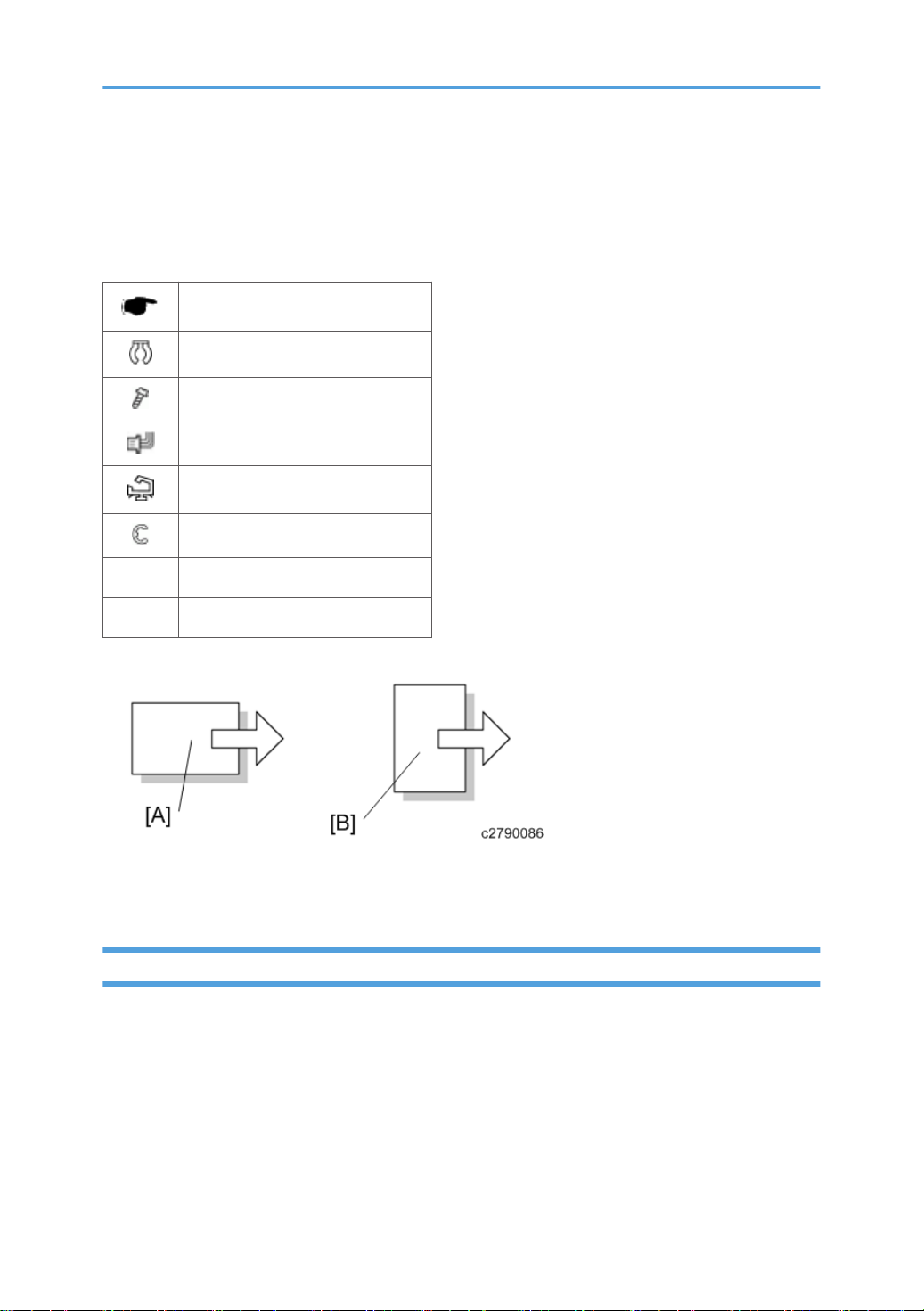
Symbols, Abbreviations and Trademarks
This manual uses several symbols and abbreviations. The meaning of those symbols and abbreviations
are as follows:
See or Refer to
Clip ring
Screw
Connector
Clamp
E-ring
SEF Short Edge Feed
LEF Long Edge Feed
[A] Short Edge Feed (SEF)
[B] Long Edge Feed (LEF)
Trademarks
Microsoft®, Windows®, and MS-DOS® are registered trademarks of Microsoft Corporation in the
United States and /or other countries.
PostScript® is a registered trademark of Adobe Systems, Incorporated.
PCL® is a registered trademark of Hewlett-Packard Company.
Ethernet® is a registered trademark of Xerox Corporation.
PowerPC® is a registered trademark of International Business Machines Corporation.
3
Page 5

Other product names used herein are for identification purposes only and may be trademarks of their
respective companies. We disclaim any and all rights involved with those marks.
4
Page 6

TABLE OF CONTENTS
Important Safety Notices................................................................................................................................... 1
Important Safety Notices............................................................................................................................... 1
Prevention of Physical Injury................................................................................................................. 1
Health Safety Conditions...................................................................................................................... 1
Observance of Electrical Safety Standards.........................................................................................1
Handling Toner...................................................................................................................................... 2
Safety and Ecological Notes for Disposal................................................................................................... 2
Symbols, Abbreviations and Trademarks.........................................................................................................3
Trademarks..................................................................................................................................................... 3
1. Product Information
Product Overview.............................................................................................................................................13
Component Layout.......................................................................................................................................13
Paper Path.................................................................................................................................................... 14
Drive Layout..................................................................................................................................................15
Machine Codes and Peripheral Configuration............................................................................................. 17
Main Frame..................................................................................................................................................17
Options......................................................................................................................................................... 17
Specifications....................................................................................................................................................18
2. Installation
Installation Requirements................................................................................................................................. 19
Check Image Quality / Setting.................................................................................................................. 19
Environment......................................................................................................................................... 19
Moving the Machine................................................................................................................................... 20
3. Preventive Maintenance
Preventive Maintenance Tables...................................................................................................................... 23
Image Quality Standards................................................................................................................................ 24
Paper Transfer Quality Standards.................................................................................................................. 25
Preparation for PM...........................................................................................................................................26
Cleaning Points.................................................................................................................................................27
4. Replacement and Adjustment
General Cautions.............................................................................................................................................29
Special Tools ................................................................................................................................................... 30
Exterior Covers................................................................................................................................................. 31
5
Page 7

Rear Cover................................................................................................................................................... 31
Paper Exit Cover (with Operation Panel)...................................................................................................32
Right Cover ..................................................................................................................................................34
Left Cover......................................................................................................................................................35
Front Cover Unit...........................................................................................................................................35
LED Optics........................................................................................................................................................ 49
LED Head......................................................................................................................................................49
Toner End Sensor.........................................................................................................................................51
PCDU.................................................................................................................................................................52
PCDU............................................................................................................................................................ 52
PCDU Cover (Right).....................................................................................................................................53
Image Transfer..................................................................................................................................................54
Image Transfer Belt Unit.............................................................................................................................. 54
After installing a new Image Transfer Belt Unit.................................................................................55
Image Transfer Belt Cleaning Unit..............................................................................................................55
Transfer Roller.............................................................................................................................................. 56
After installing a new Transfer Roller................................................................................................. 57
Drive Unit.......................................................................................................................................................... 59
Paper Feed Motor........................................................................................................................................59
Image Transfer Unit Motor..........................................................................................................................60
Fusing Motor................................................................................................................................................ 61
Drum Motor: K............................................................................................................................................. 61
Drum Motor: CMY.......................................................................................................................................62
Duplex Junction Gate Solenoid.................................................................................................................. 62
Duplex Inverter Solenoid.............................................................................................................................64
Drive Gears and Clutches........................................................................................................................... 67
Registration Clutch....................................................................................................................................... 68
Toner Supply Clutch.................................................................................................................................... 69
Bypass Clutch...............................................................................................................................................71
Duplex Intermediate Clutch.........................................................................................................................72
Duplex Paper Exit Clutch.............................................................................................................................74
Fusing................................................................................................................................................................ 76
Fusing Unit.................................................................................................................................................... 76
6
Page 8

Thermistor..................................................................................................................................................... 76
Thermostat.................................................................................................................................................... 80
Fusing Belt Unit.............................................................................................................................................81
Fusing Lamp..................................................................................................................................................84
Thermopile....................................................................................................................................................86
Paper Feed........................................................................................................................................................87
Paper Feed Roller........................................................................................................................................ 87
Friction Pad...................................................................................................................................................87
Bypass Tray Unit.......................................................................................................................................... 88
Bypass Feed Roller...................................................................................................................................... 89
Bypass Friction Pad......................................................................................................................................90
Paper Size Switch........................................................................................................................................ 91
Paper End Sensor.........................................................................................................................................91
Bypass Paper End Sensor............................................................................................................................92
Bypass Bottom Plate Home Position Sensor...............................................................................................93
Paper Transport................................................................................................................................................ 96
Fusing Entrance Sensor............................................................................................................................... 96
Duplex Sensor..............................................................................................................................................97
Registration Sensor...................................................................................................................................... 98
Reinstalling the Transport guide.......................................................................................................102
Paper Exit Sensor.......................................................................................................................................103
Paper Exit Full Sensor................................................................................................................................104
Registration Roller (Drive)......................................................................................................................... 104
Registration Roller (Driven).......................................................................................................................106
Driven Roller (Relay)................................................................................................................................. 108
Transport Roller (Relay)............................................................................................................................ 109
Paper Exit/Reverse Roller.........................................................................................................................109
Duplex Entrance Roller............................................................................................................................. 110
Duplex Intermediate Roller....................................................................................................................... 111
Duplex Exit Roller...................................................................................................................................... 111
Waste Toner...................................................................................................................................................114
Waste Toner Bottle....................................................................................................................................114
Waste Toner Bottle Sensor....................................................................................................................... 114
7
Page 9

Waste Toner Full Sensor........................................................................................................................... 115
Waste Toner Duct......................................................................................................................................116
Electrical Components...................................................................................................................................117
ID Chip Relay Board................................................................................................................................. 117
Temperature & Humidity Sensor.............................................................................................................. 118
Engine Board............................................................................................................................................. 118
When installing the new engine board...........................................................................................119
Controller Board........................................................................................................................................120
When installing the new controller board...................................................................................... 122
PSU............................................................................................................................................................. 123
High Voltage Power Supply Board (Separation)................................................................................... 123
High Voltage Power Supply Board..........................................................................................................125
PCDU Sensor Board..................................................................................................................................125
TM (ID) Sensor...........................................................................................................................................127
Before TM (ID) sensor replacement................................................................................................ 127
Replacement......................................................................................................................................129
Adjustment after the TM (ID) sensor replacement..........................................................................131
Operation Panel........................................................................................................................................ 131
Fusing Fan Motor.......................................................................................................................................134
Cooling Fan Motor....................................................................................................................................135
Reinstalling the cooling fan motor................................................................................................... 136
PSU Fan Motor.......................................................................................................................................... 137
Interlock Switch..........................................................................................................................................138
NVRAM......................................................................................................................................................139
NVRAM on the controller................................................................................................................ 139
EEPROM on the engine board........................................................................................................ 140
5. Service Table
Service Program Mode ................................................................................................................................143
SP Tables....................................................................................................................................................143
Enabling and Disabling Service Program Mode....................................................................................143
Accessing the Required Program.................................................................................................... 143
Inputting a Value or Setting for a Service Program....................................................................... 143
Exiting Service Mode....................................................................................................................... 144
8
Page 10

Service Table Key......................................................................................................................................145
SP Mode Tables.............................................................................................................................................146
SP1-XXX (Feed)......................................................................................................................................... 146
SP2-XXX (Drum).........................................................................................................................................148
SP3-XXX (Process)..................................................................................................................................... 152
SP5-XXX (Mode)....................................................................................................................................... 166
SP7-XXX (Data Log) ................................................................................................................................. 185
Updating the Firmware..................................................................................................................................202
Updating Firmware................................................................................................................................... 202
Preparation........................................................................................................................................202
Updating Procedure......................................................................................................................... 202
Error Messages.................................................................................................................................203
Firmware Update Error.....................................................................................................................203
Recovery after Power Loss............................................................................................................... 203
Handing Firmware Update Errors............................................................................................................204
Error Message Table........................................................................................................................204
Uploading/Downloading NVRAM Data....................................................................................................206
Uploading Content of NVRAM to an SD card....................................................................................... 206
Downloading an SD Card to NVRAM....................................................................................................206
Using the Debug Log.....................................................................................................................................208
Overview....................................................................................................................................................208
Switching ON and Setting UP Save Debug Log.....................................................................................208
Retrieving the Debug Log from the HDD................................................................................................. 211
Debug Log Codes..................................................................................................................................... 211
SP5857-015 Copy SD Card-to-SD Card: Any Desired Key.......................................................211
SP5857-016 Create a File on HDD to Store a Log...................................................................... 211
SP5857-017 Create a File on SD Card to Store a Log................................................................212
SMC List Card Save Function....................................................................................................................... 213
Overview....................................................................................................................................................213
SMC List Card Save......................................................................................................................... 213
Procedure...................................................................................................................................................213
File Names of the Saved SMC Lists......................................................................................................... 214
Error Messages..........................................................................................................................................215
9
Page 11

6. Troubleshooting
Self-Diagnostic Mode................................................................................................................................... 217
Self-Diagnostic Mode at Power On.........................................................................................................217
Service Call.................................................................................................................................................... 218
Service Call Conditions.............................................................................................................................218
Scanning.................................................................................................................................................... 218
LED Optics..................................................................................................................................................219
Image Processing – 1............................................................................................................................... 220
Image Processing – 2............................................................................................................................... 225
Paper Feed and Fusing............................................................................................................................. 228
Device Communication.............................................................................................................................241
Peripherals................................................................................................................................................. 243
Controller................................................................................................................................................... 244
Jam Detection.................................................................................................................................................265
Sensor Position...........................................................................................................................................265
Sensor Position...........................................................................................................................................266
Paper Feed........................................................................................................................................ 266
Bypass Tray.......................................................................................................................................266
Bank...................................................................................................................................................266
Duplex .............................................................................................................................................. 267
Electrical Component Defects.......................................................................................................................268
Image Quality................................................................................................................................................ 270
Overview....................................................................................................................................................270
Checking a Sample Printout..................................................................................................................... 271
Printer Driver Setting for Printing a Sample.....................................................................................272
Other Problems.............................................................................................................................................. 275
Blown Fuse Conditions.................................................................................................................................. 276
EGB Fuses.................................................................................................................................................. 276
PSU Fuses...................................................................................................................................................278
7. Energy Save
Energy Save................................................................................................................................................... 281
Energy Saver Modes................................................................................................................................ 281
Timer Settings.................................................................................................................................... 281
10
Page 12

Eco Night Mode............................................................................................................................... 282
Weekly Timer.................................................................................................................................... 282
Fusing Off Mode...............................................................................................................................282
Return to Stand-by Mode.................................................................................................................283
Recommendation..............................................................................................................................283
Energy Save Effectiveness........................................................................................................................ 283
Paper Save.....................................................................................................................................................286
Effectiveness of Duplex/Combine Function............................................................................................ 286
1. Duplex:..........................................................................................................................................286
2. Combine mode:............................................................................................................................286
3. Duplex + Combine:...................................................................................................................... 287
Recommendation..............................................................................................................................287
11
Page 13
1. Product Information
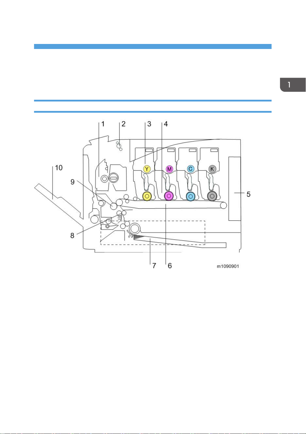
Product Overview
Component Layout
1. Fusing Unit
2. Paper Exit/Reverse Roller
3. Toner Bottle
4. PCDU
5. Engine Board/Controller Board
6. Image Transfer Belt Unit
7. Paper Feed Tray
8. Registration Roller
9. Transfer Roller
10. Bypass Tray Unit
13
Page 14
1. Product Information
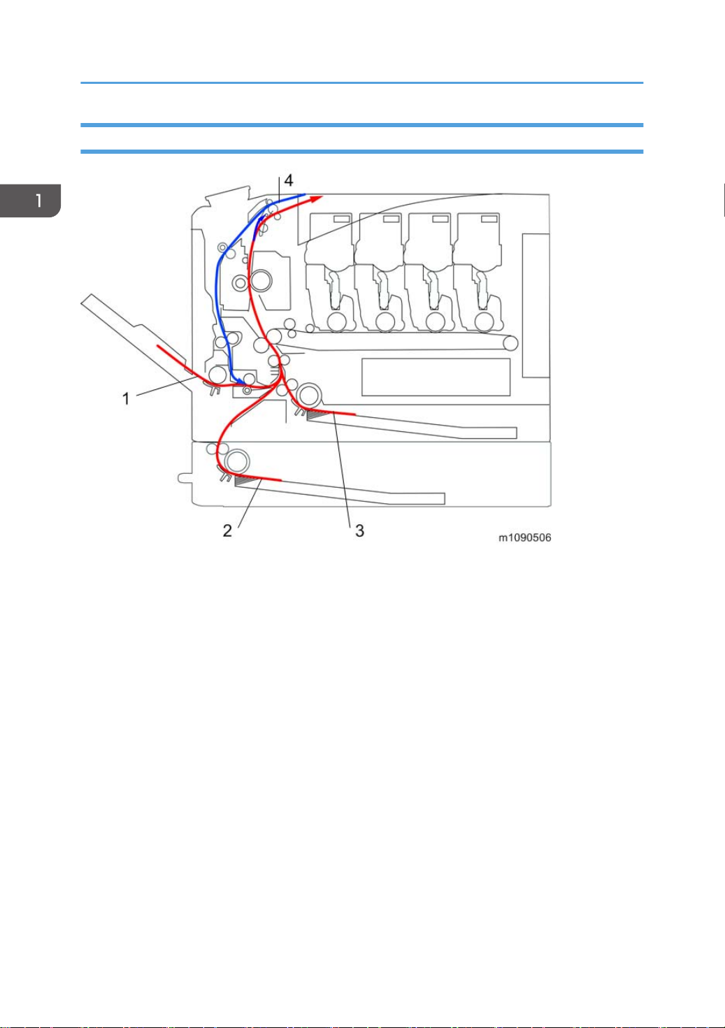
Paper Path
1. Bypass Tray
2. Optional Paper Feed Tray
3. Standard Paper Feed Tray
4. Duplex Feed Path
14
Page 15
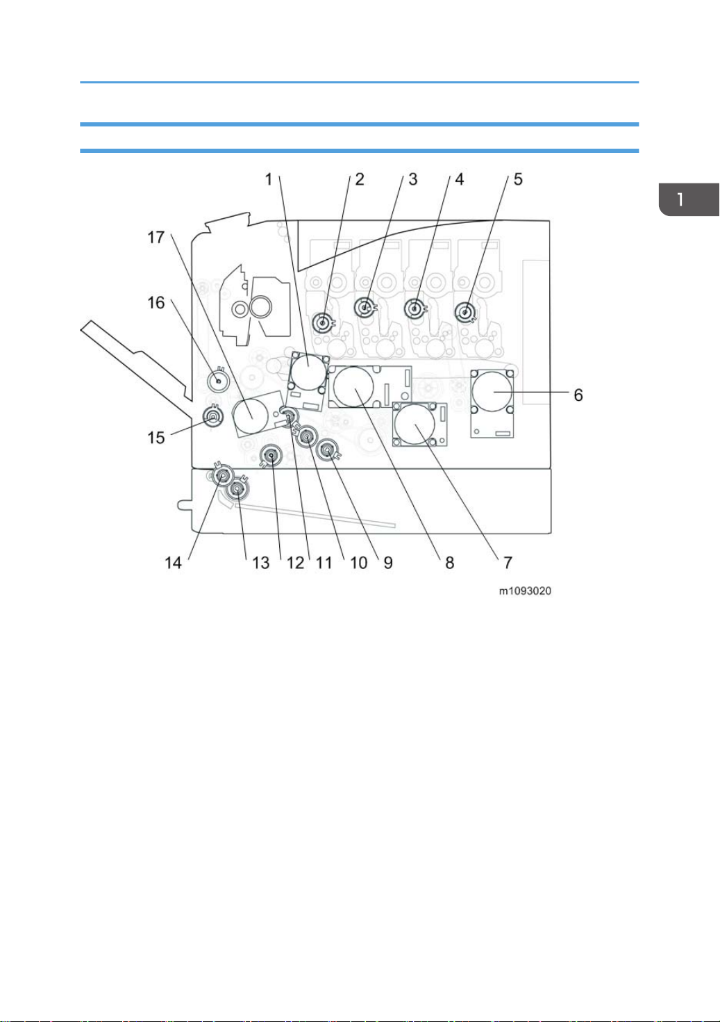
Drive Layout
Product Overview
1. Image Transfer Unit Motor
2. Toner Supply Clutch (Y)
3. Toner Supply Clutch (M)
4. Toner Supply Clutch (C)
5. Toner Supply Clutch (K)
6. Drum Motor: K
7. Fusing Motor
8. Drum Motor: CMY
9. Paper Feed Clutch
10. Relay Clutch
11. ITB (Image Transfer Belt) Contact Clutch
12. Registration Clutch
13. Paper Feed Clutch
15
Page 16

1. Product Information
14. Grip Roller Clutch
15. Duplex Intermediate Clutch
16. Bypass Clutch
17. Paper Feed Motor
16
Page 17

Machine Codes and Peripheral Configuration
Machine Codes and Peripheral Configuration
Main Frame
item Machine Code Remarks
SP C730DN M109 NEW
Options
item Machine Code Remarks
Paper Feed Unit TK2000 M406 NEW
Hard Disk Drive Option Type C730 M417-01 NEW
Memory Unit Type N 1GB M417-03 NEW
IEEE802.11 Interface Unit Type O M417-06 NEW, *1
IPDS Unit Type C730 M417-10(NA)
M417-11(EU)
M417-12(Asia/CHN)
Camera Direct Print Card Type L M417-15 NEW
SD card for NetWare printing Type M M417-16 NEW
IEEE1284 Interface Board Type A B679 *1
VM CARD Type W M417-19(NA)
M417-20(EU)
M417-21(Asia/CHN)
*1: You can only install one of these at a time.
*2: You cannot install this without the HDD.
NEW
NEW, *2
17
Page 18

1. Product Information
Specifications
See "Appendices" for the following information:
• General Specifications
• Supported Paper Sizes
• Software Accessories
• Optional Equipment
• Other Specifications
18
Page 19
2. Installation
Installation Requirements
Check Image Quality / Setting
This machine is installed by the user.
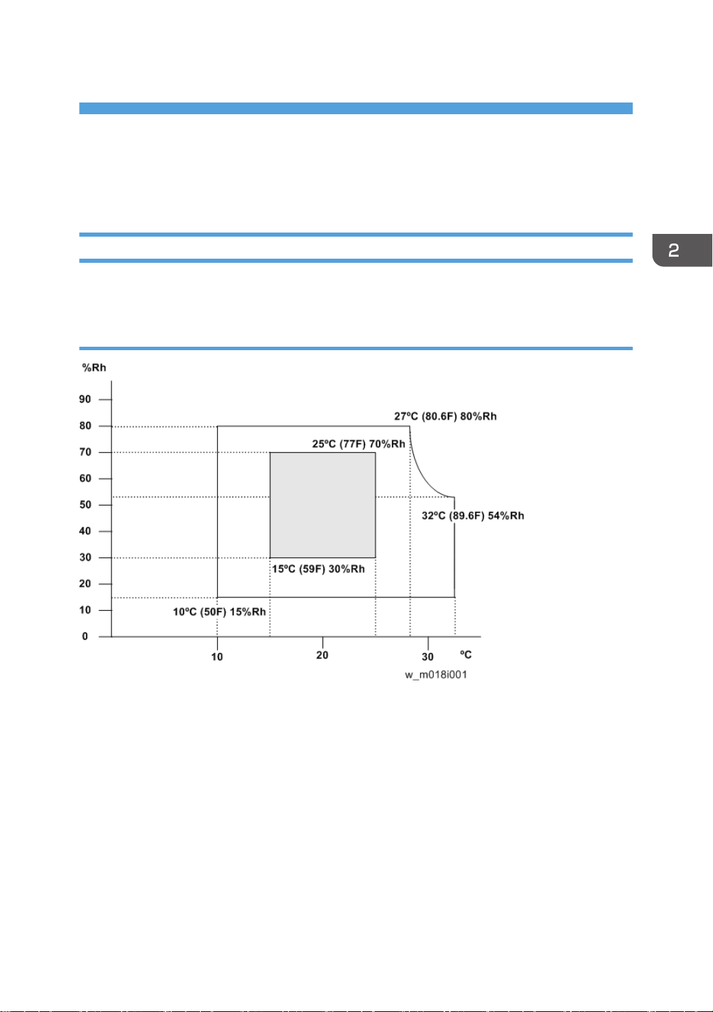
Environment
1. Temperature Range: 10°C to 32°C (50°F to 89.6°F)
2. Humidity Range: 15% to 80% RH
3. Ambient Illumination: Less than 2,000 lux (do not expose to direct sunlight)
4. Ventilation: 3 times/hr/person
5. Do not install the machine at locations over the following heights above sea level.
All areas except for China: 2,500 m (8,125 ft.)
China: 2,000 m (6,562 ft.)
6. Atmospheric pressure: more than 740 hPa.
19
Page 20

2. Installation
Moving the Machine
• It is dangerous to handle the power cord plug with wet hands. Doing so could result in electric
shock.
• Unplug the power cord from the wall outlet before you move the machine. While moving the
machine, take care that the power cord is not damaged under the machine. Failing to take these
precautions could result in fire or electric shock.
• When disconnecting the power cord from the wall outlet, always pull the plug, not the cord. Pulling
the cord can damage the power cord. Use of damaged power cords could result in fire or electric
shock.
• The printer weighs approximately 40 kg (88.2 lb.). When moving the printer, use the inset grips on
both sides, and lift slowly in pairs. The printer will break or cause injury if dropped.
• When moving the printer after use, do not take out any of the toners, nor the waste toner bottle to
prevent toner spill inside the printer.
• Do not hold the control panel while moving the printer. Doing so may damage the control panel,
cause a malfunction, or result in injury.
• Be careful when moving the printer. Take the following precautions:
• Turn off the main power.
• Close all covers and trays, including the front cover and bypass tray.
• If optional paper feed units are attached, remove them from the printer and move them separately
• Be sure to place the printer on a smooth and stable place.
• Keep the printer level and carry it carefully, taking care not to jolt or tip it. Rough handling may
cause a malfunction or damage the hard disk or memory, resulting in loss of stored files.
• Protect the printer from strong shocks. Impact can damage the hard disk and cause stored files to
be lost. As a precautionary measure, files should be copied to another computer.
20
Page 21

Installation Requirements
1. Be sure to check the following:
The power switch is turned off.
The power cord is unplugged from the wall outlet.
The interface cable is unplugged from the printer.
2. If Paper Feed Unit are attached, remove them.
3. Lift the printer with two people by using the inset grips on both sides of the printer, and
then move it horizontally to the place where you want to install it.
4. If you removed Paper Feed Unit, reattach them.
• Be sure to move the printer horizontally. To prevent toner from scattering, move the printer
slowly.
21
Page 22

3. Preventive Maintenance
Preventive Maintenance Tables
See "Appendices" for the following information:
• Preventive Maintenance Items
23
Page 23
3. Preventive Maintenance
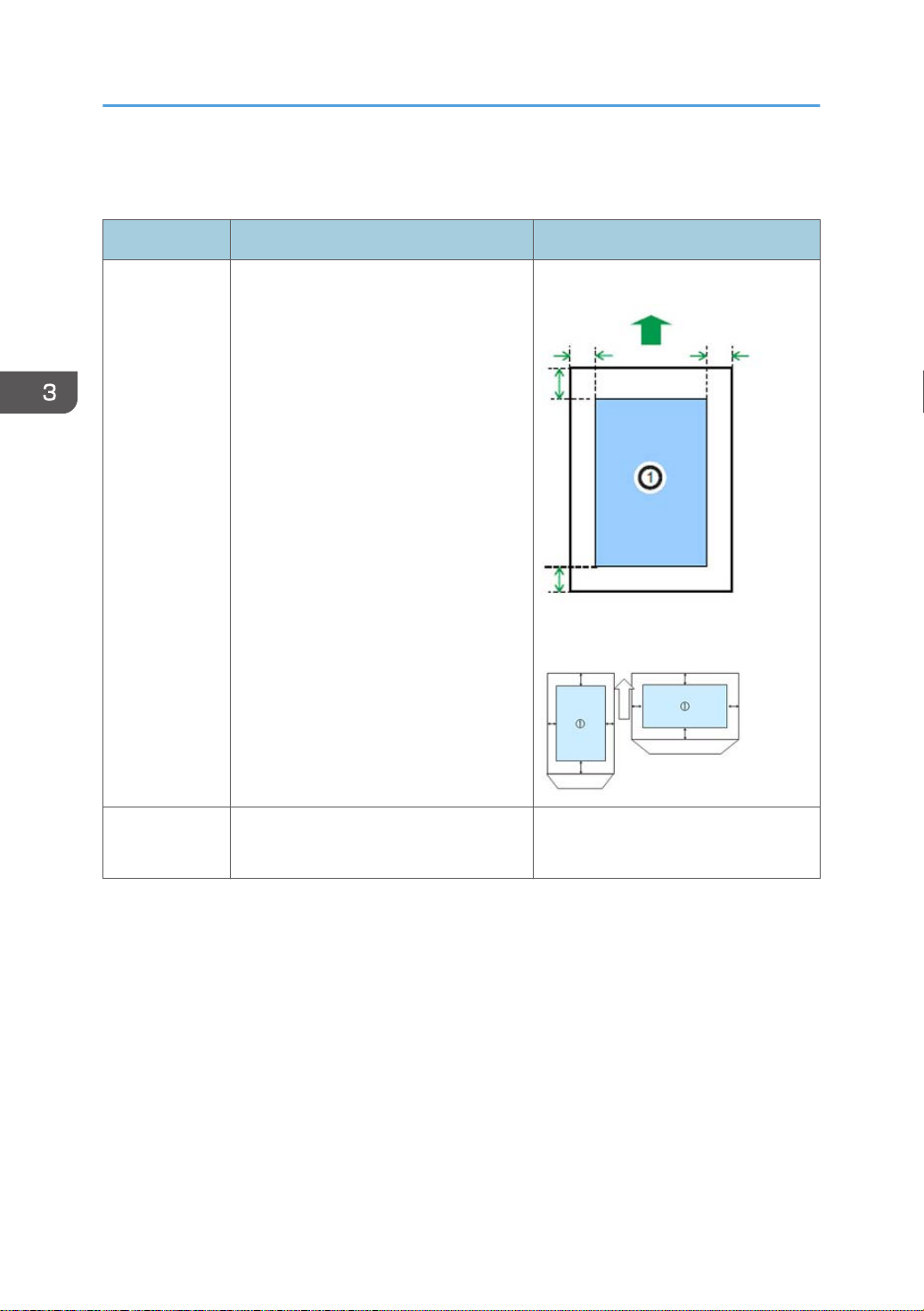
Image Quality Standards
Item Specification Remarks
Except Envelopes
Except Envelopes
The standard print area of a sheet is the
area enclosed by margins of 4.3 mm
Assured Image
Area
from all sides of the sheet.
Envelopes
The 15mm excluding the flap portion
from the rear end / tip of the sheet,
except for the region of the left and right
ends 10mm.
Envelopes
24
Magnification
Error
Main: ±0.50% or more
Scale
Sub: ±0.50% or less
Page 24

Paper Transfer Quality Standards
Item Specification Remarks
Single Side:
Width: 0±2.0mm (Main Scan Direction)
Vertical: Office / All Environments 0±2.0mm (Sub Scan
Direction)
(In an environment of 23 deg C / 50% is vertical: 0 ±
1.5mm
Registration
Duplex:
Width: 0±3.0mm (Main Scan Direction)
Vertical: Office / All Environments 0±4.0mm (Sub Scan
Direction)
(In an environment of 23 deg C / 50% is vertical: 0 ±
3.5mm
Paper Transfer Quality Standards
Scale
Single Side:
±1.0mm/100mm or less (Less than B5 SEF)
±1.0mm/200mm or less (B5 SEF or more, tray 1 /
Bypass tray)
Skew
These standards are determined using the standard paper with the standard conditions. The value may
change depend on the environmental conditions such as temperature, humidity, and used paper, etc.
±1.2mm/200mm or less (B5 SEF or more, Optional
Tray)
Duplex:
±1.5mm/100mm or less (Less than B5 SEF)
±1.0mm/100mm or less (B5 SEF or more)
Except if the
paper is
longer than
432mm.
25
Page 25

3. Preventive Maintenance
Preparation for PM
See "Appendices" for the following information:
• Meter Click Mode
26
Page 26

Cleaning Points
See "Appendices".
Cleaning Points
27
Page 27

4. Replacement and Adjustment
RTB 54
Avoid touching areas of the PSU that may carry charge.
General Cautions
• Do not hold down the power switch for 6 seconds or longer when turning off the machine. Doing
so may result in damage to the hard disk or memory, leading to malfunctions.
• Before disassembling or assembling parts of the main machine and peripherals, make sure that the
power cord of the main machine is unplugged.Since this machine uses a DC switch, there is a weak
current even after the power cord is unplugged.
Follow the steps below when disassembling the machine.
1. Press the power switch off.
2. Unplug the power cord.
3. Press the power switch once to discharge the remaining current.
When the power cord is plugged in, the machine may power itself on even though the power switch
button is not pressed.
29
Page 28

4. Replacement and Adjustment
Special Tools
Part Number Description Q’ty
B6455010 SD Card 128MB 1
B6455020 SD Card 1GB 1
• A PC (Personal Computer) is required for creating the Encryption key file on an SD card when
replacing the controller board for a model in which HDD encryption has been enabled.
30
Page 29
Exterior Covers
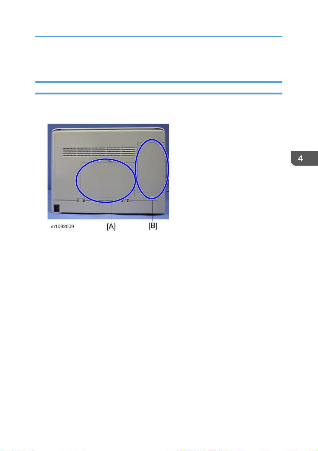
Rear Cover
1. Memory/HDD cover [A]
2. Cable cover [B]
Exterior Covers
31
Page 30
4. Replacement and Adjustment
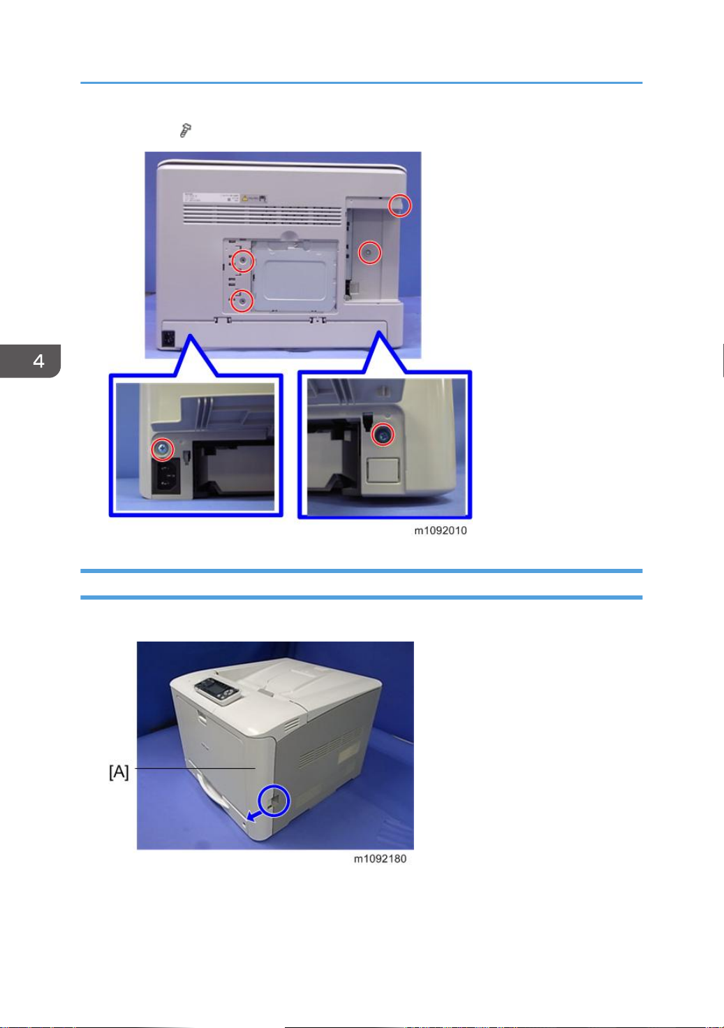
3. Rear cover ( ×6)
Paper Exit Cover (with Operation Panel)
1. Open the Front cover [A]
32
Page 31

2. Open the Upper cover [A]
3. Connector cover [A] ( ×1)
Exterior Covers
33
Page 32

4. Replacement and Adjustment
4. Paper exit cover [A] ( ×3, ×1)
34
Right Cover
1. Paper exit cover ( page 32)
2. Rear cover ( page 31)
3. Open the inner cover
Page 33

4. Right cover ( ×4)
Left Cover
Exterior Covers
• Remove the Waste Toner Bottle before you remove the Left Cover, so as not to disperse the toner.
1. Waste toner bottle. ( page 114)
2. Paper exit cover ( page 32)
3. Rear cover ( page 31)
4. Left cover ( ×3)
Front Cover Unit
1. Bypass tray unit ( page 88)
35
Page 34

4. Replacement and Adjustment
2. Open the Front cover.
3. Bracket [A] ( ×2)
4. Close the Front cover slightly, and than remove the wire [A].
36
Page 35

5. Brackets [A] and [B]. ( ×2)
6. Connectors ( ×2)
Exterior Covers
7. Duplex paper exit clutch [A]( ×1)
8. Bypass clutch [B]( ×1)
37
Page 36

4. Replacement and Adjustment
9. Gear [A] and Duplex intermediate clutch [B] ( ×1)
• [A]: Gear (This gear has a round hole.)
• [B]: Duplex intermediate clutch
10. Gear unit [A] ( ×2)
11. Spacer [A]
38
Page 37

12. Gears [B], [C], [D] ( ×1)
Exterior Covers
• The hole in the gear [B] is in the form of a ‘D’.
39
Page 38

4. Replacement and Adjustment
13. Cam [A]
14. Loosen the tension of the spring [A], and then remove the Harness guide [B]. ( ×2)
15. Cover [A] ( ×2)
40
Page 39

16. Power switch [A] ( ×1)
17. Harness guide [B] ( ×1, ×1)
18. Harness guide [A] (hook×2)
Exterior Covers
41
Page 40

4. Replacement and Adjustment
19. Connectors ( ×3)
20. Ground plate [A] ( ×2)
42
Page 41

21. Gears [A], [B] ( ×1)
Exterior Covers
• The hole in the gears [A] and [B] is in the form of a ‘D’.
43
Page 42

4. Replacement and Adjustment
22. Bearing [A]
23. Close the Front cover slightly.
24. Paper feed roller ( page 87)
44
Page 43

25. Snaps ( ×3)
Exterior Covers
• Be careful not to lose the spring [A].
26. Open the Front cover.
45
Page 44

4. Replacement and Adjustment
27. Shaft [A]
28. Close the Front cover slightly.
29. Shaft [A]
30. Open the Front cover.
46
Page 45

31. Transport unit [A] ( ×8)
Exterior Covers
47
Page 46

4. Replacement and Adjustment
32. Front cover unit [A] ( ×6)
48
• Be careful not to break the Mylar [A] during the exchange.
Page 47

LED Optics
LED Optics
LED Head
1. Open the Upper inner cover, and then cover the PCDUs with a sheet of paper, to prevent
foreign objects from falling into the PCDUs. ( page 52)
2. Remove the snaps and flat cable from the LED head [A].
49
Page 48

4. Replacement and Adjustment
3. Slide the Toner end sensor unit [A].
4. Remove the connector from the Toner end sensor [A].
50
5. LED head [A]
• The Flat cables of the LED heads have different colors. They have a fixed order.
• If you remove the Flat cables of the LED heads, during re-assembly connect them so that they
overlap in the order of Y / M / C / K.
Page 49

[A]: Flat cable: EGB: LED head Y
[B]: Flat cable: EGB: LED head M
[C]: Flat cable: EGB: LED head C
LED Optics
[D]: Flat cable: EGB: LED head K
Toner End Sensor
1. LED head ( page 49)
2. Toner end sensor [A] ( ×1)
51
Page 50

4. Replacement and Adjustment
RTB 27
Important Information about Installing a Used PCDU
PCDU
PCDU
1. Open the Upper cover.
2. Release the lock [A], and open the Upper inner cover [B].
3. PCDUs [A]
• All PCDUs (Cyan, Magenta, Yellow, and Black) have a new unit detecting mechanism.
Technicians do not need to reset counters after replacing, even if not all the PCDUs are
replaced at the same time.
52
Page 51

PCDU Cover (Right)
1. PCDU ( page 52)
2. PCDU cover [A] (hook ×2)
PCDU
53
Page 52

4. Replacement and Adjustment
Image Transfer
Image Transfer Belt Unit
1. Open the Front cover.
2. Fusing unit ( page 76)
3. Release the locks [A], and then pull out the Image transfer belt unit [B].
• Before you install the image transfer belt, make sure that the white lever [A] is pulled out to the
position shown in this photo.
54
Page 53

Image Transfer
After installing a new Image Transfer Belt Unit
• Print out the logging data using SP5-990-004 before you replace either the transfer belt unit or the
transfer roller.
• The Image Transfer Belt Unit as a supply part is equipped with a new unit detection mechanism and
does not require counter reset. The Paper Transfer Roller as a supply part is kitted together with the
Image Transfer Belt unit and does not require counter reset, since it will be replaced at the same
time as the Image Transfer Belt Unit.
Part replaced Action
1 Image Transfer Belt Unit
2 Paper Transfer Roller
As mentioned above, action is necessary only in the following two cases:
1.If you are replacing the image transfer belt unit
SP7-804-017 (PM Counter Clear ITB Unit)
SP7-804-060 (PM Counter Clear Life: ITB Unit)
If you are replacing the image transfer belt unit, you should execute SP7-804-017, for correct
control depending on the rotation distance. But, if you execute only SP7-804-017, the counter for
displaying the unit life is not cleared. So you must also clear the counter by executing
SP7-804-060 (PM Counter Clear Life: ITB Unit).
2.If you are replacing the paper transfer roller
SP7-804-022 (PM Counter Clear PTR Unit)
SP7-804-061 (PM Counter Clear Life: PTR Unit)
If you are replacing the paper transfer roller, you should execute SP7-804-022, for correct control
depending on the rotation distance. But, if you execute only SP7-804-022, the counter for
displaying the unit life is not cleared. So you must also clear the counter by executing
SP7-804-061 (PM Counter Clear Life: PTR Unit).
1. Execute SP7-804-017 and SP7-804-060
2. Turn off the machine, and then turn it back on.
1. Execute SP7-804-022 and SP7-804-061
2. Turn off the machine, and then turn it back on
Image Transfer Belt Cleaning Unit
1. Image transfer belt unit ( page 54)
55
Page 54

4. Replacement and Adjustment
2. Belt guide roller [A] (hook×2)
3. Image transfer belt cleaning unit [A] ( ×2)
• When you change the Transfer belt cleaning unit, dust the new one with toner as a lubricant.
Transfer Roller
1. Open the Front cover.
56
Page 55

Image Transfer
2. Remove the Transfer roller [A] with green handles.
After installing a new Transfer Roller
• Print out the logging data using SP5-990-004 before you replace either the transfer belt unit or the
transfer roller.
Part replaced Action
1. Execute SP7-804-017 and SP7-804-060
1 Image transfer belt unit
2. Turn off the machine, and then turn it back on.
1. Execute SP7-804-022 and SP7-804-061
2 Paper transfer roller
2. Turn off the machine, and then turn it back on
As mentioned above, action is necessary only in the following two cases:
1.If you are replacing the image transfer belt unit
SP7-804-017 (PM Counter Clear ITB Unit)
SP7-804-060 (PM Counter Clear Life: ITB Unit)
If you are replacing the image transfer belt unit, you should execute SP7-804-017, for correct
control depending on the rotation distance. But, if you execute only SP7-804-017, the counter for
displaying the unit life is not cleared. So you must also clear the counter by executing
SP7-804-060 (PM Counter Clear Life: ITB Unit).
2.If you are replacing the paper transfer roller
SP7-804-022 (PM Counter Clear PTR Unit)
SP7-804-061 (PM Counter Clear Life: PTR Unit)
57
Page 56

4. Replacement and Adjustment
If you are replacing the paper transfer roller, you should execute SP7-804-022, for correct control
depending on the rotation distance. But, if you execute only SP7-804-022, the counter for
displaying the unit life is not cleared. So you must also clear the counter by executing
SP7-804-061 (PM Counter Clear Life: PTR Unit).
• The Paper Transfer Roller as a supply part is kitted together with the Image Transfer Belt unit
and does not require counter reset, since it will be replaced at the same time as the Image
Transfer Belt Unit.
58
Page 57

Drive Unit
Paper Feed Motor
1. Right cover ( page 34)
2. Bracket ( page 60 "Image Transfer Unit Motor")
3. Harness guide [A] (hook x1)
4. Release the harness guide [B] ( ×1).
Drive Unit
5. Bracket [A] ( ×1, ×3)
59
Page 58

4. Replacement and Adjustment
6. Paper feed motor [A] ( ×3)
Image Transfer Unit Motor
1. Right cover ( page 34)
2. Bracket [A] ( ×4)
60
Page 59

3. Image transfer unit motor [A] ( ×1, ×3)
Fusing Motor
Drive Unit
1. Right cover ( page 34)
2. Fusing motor [A] ( ×1, × 3)
Drum Motor: K
1. Right cover ( page 34)
61
Page 60

4. Replacement and Adjustment
2. Drum motor: K ( ×1, ×3)
Drum Motor: CMY
1. Right cover ( page 34)
2. Drum motor: CMY [A] ( ×1, ×3)
Duplex Junction Gate Solenoid
1. Fusing fan ( page 134)
62
Page 61

2. Bracket [A] ( ×2, ×2)
3. Sensor [A]
4. Remove the solenoid from the bracket ( ×2, ×1, × 1).
Drive Unit
• Push the connector holder [B] out to facilitate access to the screw with a screwdriver.
63
Page 62

4. Replacement and Adjustment
5. Duplex junction gate solenoid [A]
Duplex Inverter Solenoid
1. Right cover ( page 34)
2. Bracket [A] ( ×6, × 3)
3. Gear box bracket [A] ( ×3)
64
Page 63

4. Remove the solenoid from the bracket [B] ( ×5, Spring ×1).
• Be careful not to let gears fall out of the box and become lost.
Drive Unit
• Refer to the picture below showing the location of each gear.
65
Page 64

4. Replacement and Adjustment
5. Remove the cover [A] to pull the connector out.
66
• To remove the cover [A], pull it diagonally as shown by the blue arrow in the picture above.
This cover is fixed by hooks on the lower and right sides.
Page 65

6. Duplex inverter solenoid [A]
Drive Gears and Clutches
Drive Unit
1. Right cover ( page 34)
2. Paper feed motor ( page 59)
3. Harness guide [A] ( ×2)
4. Harness guide (inner) [A] ( ×5)
1. Relay clutch
2. Paper feed clutch
3. ITB (image transfer belt) Contact Clutch
67
Page 66

4. Replacement and Adjustment
5. Drive gears and clutches [A]
Registration Clutch
1. Image transfer unit motor ( page 60)
2. Paper feed motor ( page 59)
3. Drive gears and clutches ( page 67)
68
Page 67

4. Bracket [A] ( ×2)
5. Registration clutch [A]
Drive Unit
Toner Supply Clutch
1. Right cover ( page 34)
69
Page 68

4. Replacement and Adjustment
2. Cover brackets [A] ( ×2 each)
3. Clips and connectors ( ×1, ×1 each)
70
Page 69

4. Toner supply clutch [A]
Bypass Clutch
Drive Unit
1. Open the front cover.
2. Bracket [A] ( x1)
71
Page 70

4. Replacement and Adjustment
3. Bypass clutch [A] ( x1, x1)
Duplex Intermediate Clutch
1. Open the front cover.
2. Brackets [A] [B] ( x2)
72
Page 71

3. Connector x1
4. Gear [A] and clip
Drive Unit
73
Page 72

4. Replacement and Adjustment
5. Duplex intermediate clutch [A]
• Make sure that the harness [A] is installed as shown above when reinstalling the duplex
intermediate clutch.
Duplex Paper Exit Clutch
1. Open the front cover.
74
Page 73

2. Bracket [A] ( x1)
3. Duplex paper exit clutch [A] ( x1)
Drive Unit
75
Page 74

4. Replacement and Adjustment
Fusing
• Make sure that the fusing unit is cool before you touch it. The fusing unit can be very hot. Make sure
to restore the insulators, shields, etc after you service the fusing unit.
Fusing Unit
1. Open the front cover.
2. Hold the fusing unit lock levers [A] while pulling out the fusing unit.
3. Fusing unit [B]
76
Thermistor
1. Fusing unit ( page 76)
Page 75

2. Fusing upper cover [A] (Stepped screw×4)
3. Fusing lower cover [A] (Stepped screw ×2, ×1)
4. Fusing entrance guide [B] (Stepped screw ×2)
5. Thermistor bracket [C] ( ×2)
Fusing
77
Page 76

4. Replacement and Adjustment
78
• Put the fusing lower cover as shown above in order to prevent damaging the thermistor [A].
Page 77

Fusing
• The guide [A] of the fusing lower cover can be adjusted to right and left by removing the two
screws.
6. Thermistor ×2 [A] ( ×1 each)
79
Page 78

4. Replacement and Adjustment
7. Thermistor bracket [A] ( ×1, ×1)
8. Thermistor [A] ( ×1)
80
Thermostat
1. Fusing unit ( page 76)
2. Fusing upper cover ( page 76 "Thermistor")
3. Fusing lower cover ( page 76 "Thermistor")
4. Thermostat (left) [A] ( ×2)
Page 79

5. Thermostat bracket [B] ( ×3)
6. Thermostat (right) [A] ( ×2 each)
Fusing
• The thermostat (right) cannot be attached to the socket for the thermostat (left). But the
thermostat (left) can be attached to the socket for the thermostat (right).
Fusing Belt Unit
1. Fusing unit ( page 76)
2. Fusing upper cover ( page 76 "Thermistor")
3. Fusing lower cover ( page 76 "Thermistor")
81
Page 80

4. Replacement and Adjustment
4. Spring ×2 [A]
5. Guide [A] (spring ×2, hook ×2)
82
Page 81

6. Guide plate [A] (spring ×2, hook ×2)
• Push the lever backward as shown by the blue arrow in the picture above. Then pay attention
to the shape (D-shape) of the joints in order to pull the guide plate off the axis smoothly.
Fusing
7. Bracket [A] ( ×10)
83
Page 82

4. Replacement and Adjustment
8. Fusing belt unit [A] ( × 4)
• To detach easily, move the ends of the fusing belt unit sideways to release the hold. Then try to
pull it out.
84
Fusing Lamp
1. Fusing belt unit ( page 81)
Page 83

2. Pull out the fusing lamp with the base [A] from the belt assembly.
3. Remove the fusing lamp [A] from the base.
Fusing
• When you reassemble, pay attention to the shape (bracket [A] and [B]) as shown in the
picture below.
85
Page 84

4. Replacement and Adjustment
Thermopile
1. Fusing unit ( page 76)
2. Thermopile bracket [A] ( ×2)
3. Thermopile [A] ( ×1, hook ×2)
86
Page 85

Paper Feed
Paper Feed Roller
1. Pull out the Standard paper tray [A].
Paper Feed
2. Slide the Paper feed shaft [A] to the right side, and then slide the Paper feed roller [B] to
the left side, and remove it.
Friction Pad
1. Remove the Paper tray unit from the machine before removing the Friction pad.
87
Page 86

4. Replacement and Adjustment
2. Friction pad [A] (hook×2)
Bypass Tray Unit
1. Open the Front cover.
2. Remove the snaps [A] from the Shaft, and then remove the shaft. ( ×2)
88
Page 87

3. Pull out the Front cover Unit [B].
Paper Feed
Bypass Feed Roller
1. Bypass tray unit ( page 88)
2. Bypass feed roller cover [A]
• Take off the claws [B] on the back of the cover.
89
Page 88

4. Replacement and Adjustment
3. Bypass feed roller [A]
Bypass Friction Pad
1. Bypass feed roller ( page 89)
2. Guide [A] ( ×2)
3. Plate [A] ( ×4)
90
Page 89

4. Bypass friction pad [A]
Paper Size Switch
1. Standard paper tray ( page 89)
2. Paper size switch [A] ( ×1, hook×2)
Paper Feed
Paper End Sensor
1. Standard paper tray ( page 87 "Paper Feed Roller")
91
Page 90

4. Replacement and Adjustment
2. Sensor cover [A] ( ×2)
3. Paper end sensor [A] ( ×1, hook×2)
Bypass Paper End Sensor
1. Bypass tray unit ( page 88)
2. Bypass feed roller cover ( page 89 "Bypass Feed Roller")
92
Page 91

3. Bypass paper end sensor [A] ( ×1, ×1, ×1)
Bypass Bottom Plate Home Position Sensor
Paper Feed
1. Open the Front cover.
2. Cover [A] ( ×2)
3. Power switch [A] ( ×1)
93
Page 92

4. Replacement and Adjustment
4. Harness guide [B] ( ×1, ×1)
5. Harness guide [A] (hook×2)
94
6. Connectors ( ×3)
Page 93

Paper Feed
7. Ground plate [A] ( ×2)
8. Insert a flat-blade screwdriver into the outside of the Bypass bottom plate Home position
sensor [A], and then pull out.
95
Page 94

4. Replacement and Adjustment
Paper Transport
Fusing Entrance Sensor
1. Open the Front cover.
2. Sensor cover [A] (hook×2)
3. Sensor unit [A] ( ×2)
96
Page 95

4. Fusing entrance sensor [A] ( ×1, ×1)
Duplex Sensor
1. Open the Front cover.
Paper Transport
2. Transfer roller (Relay) ( page 109)
3. Roller upper cover [A] ( ×1)
97
Page 96

4. Replacement and Adjustment
4. Sensor unit [A] ( ×1)
5. Duplex sensor [A] ( ×1, hook×2)
Registration Sensor
1. Paper feed tray ( page 87)
2. Open the Front cover.
98
Page 97

3. Loosen the Transport guide [A] ( ×2 )
4. Pull the outside of the Transport guide (left/right).
Paper Transport
5. Pull the inside of the Transport guide (left/right).
99
Page 98

4. Replacement and Adjustment
6. Insert a flat-blade screwdriver into the outside of the Transport guide (left/right), and
then pull out.
7. Transport guide (left/right) [A]
8. Slide the Registration position stopper inside (left/right) [A].
100
Page 99

Paper Transport
9. Pull out the Transport guide (upper), and then remove the Sensor plate [A]. ( ×4 )
• Take care not to catch the harness between the plate and the screw hole.
10. Registration sensor [A] ( ×1, ×1 )
101
Page 100

4. Replacement and Adjustment
Reinstalling the Transport guide
1. Set the Transport guide (left/right) [A] on the Registration roller (Driven).
2. Install the Transport guide (front), and then fit the screws loosely. ( ×2)
102
3. Turn your hands to the back of the Transport guide (front), and then insert the pawls in the
Transport guide (left/right).
 Loading...