

Page 1
®
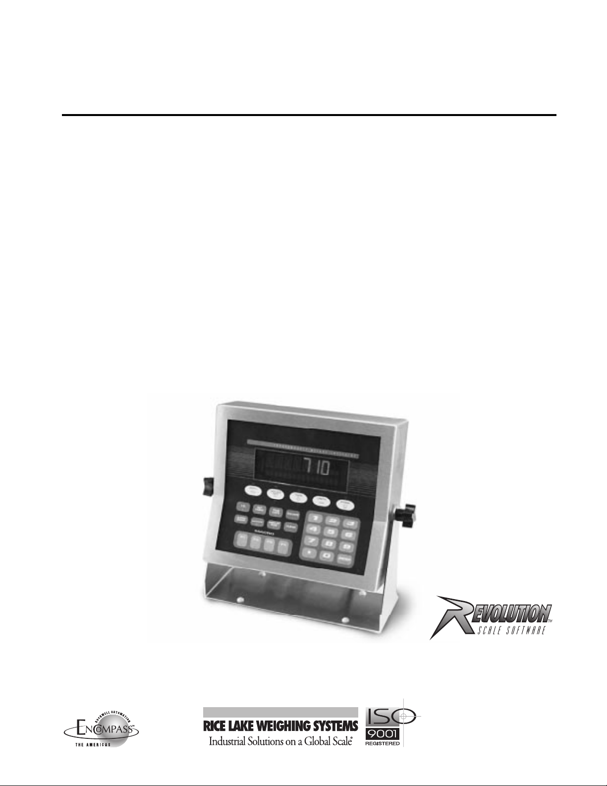
IQ plus
Digital Weight Indicator
710
Version 1.4
Installation Manual
45391
Page 2

Contents
About This Manual................................................................................................................................... 1
1.0 Introduction.................................................................................................................................. 1
1.1 Operating Modes ........................................................................................................................... 1
1.2 Front Panel Display ........................................................................................................................ 2
1.3 Indicator Operations....................................................................................................................... 3
1.3.1 Toggle Gross/Net Mode....................................................................................................................... 3
1.3.2 Toggle Units......................................................................................................................................... 3
1.3.3 Zero Scale............................................................................................................................................ 3
1.3.4 Acquire Tare......................................................................................................................................... 3
1.3.5 Remove Stored Tare Value................................................................................................................... 3
1.3.6 Print Ticket........................................................................................................................................... 3
1.3.7 Display or Change Time and Date ........................................................................................................ 3
1.3.8 Display or Change Setpoint Value......................................................................................................... 3
1.3.9 Turn Setpoint On or Off ........................................................................................................................ 3
1.3.10 Display or Clear Accumulator ............................................................................................................... 3
2.0 Installation................................................................................................................................... 4
2.1 Unpacking and Assembly............................................................................................................... 4
2.2 Enclosure Disassembly................................................................................................................... 4
2.3 Cable Connections......................................................................................................................... 4
2.3.1 Load Cells............................................................................................................................................ 5
2.3.2 Serial Communications......................................................................................................................... 6
2.3.3 Digital I/O ............................................................................................................................................. 6
2.3.4 Analog Output...................................................................................................................................... 6
2.4 Analog Output Module Installation.................................................................................................. 6
2.5 Enclosure Reassembly................................................................................................................... 7
2.6 Board Removal .............................................................................................................................. 7
2.7 Battery Replacement...................................................................................................................... 7
2.8 Replacement Parts......................................................................................................................... 8
3.0 Configuration.............................................................................................................................. 13
3.1 Configuration Methods................................................................................................................. 13
3.1.1 Revolution Configuration..................................................................................................................... 13
3.1.2 EDP Command Configuration............................................................................................................. 13
3.1.3 Front Panel Configuration................................................................................................................... 14
3.2 Menu Structures and Parameter Descriptions .............................................................................. 15
3.2.1 Configuration Menu............................................................................................................................ 16
3.2.2 Format Menu...................................................................................................................................... 19
3.2.3 Calibration Menu ................................................................................................................................ 21
3.2.4 Serial Menu ........................................................................................................................................ 22
3.2.5 Program Menu ................................................................................................................................... 24
3.2.6 Print Format Menu.............................................................................................................................. 26
3.2.7 Setpoints Menu.................................................................................................................................. 27
3.2.8 Digital Input Menu............................................................................................................................... 31
3.2.9 Analog Output Menu .......................................................................................................................... 32
3.2.10 Version Menu..................................................................................................................................... 32
4.0 Calibration.................................................................................................................................. 33
4.1 Front Panel Calibration................................................................................................................. 33
4.2 EDP Command Calibration........................................................................................................... 34
4.3 Revolution
4.4 More About Calibration ................................................................................................................ 36
4.4.1 Zero Deadload A/D Counts ................................................................................................................ 36
4.4.2 Calculating the Span Coefficient......................................................................................................... 36
Copyright © 2000 Rice Lake Weighing Systems. All rights reserved. Printed in the United States of America.
™
Calibration................................................................................................................ 35
Specifications subject to change without notice.
Version 1.4, March 2000
Page 3

ii
5.0 EDP Commands.......................................................................................................................... 37
5.1 The EDP Command Set............................................................................................................... 37
5.1.1 Key Press Commands........................................................................................................................ 37
5.1.2 Reporting Commands........................................................................................................................ 38
5.1.3 The RESETCONFIGURATION Command........................................................................................... 38
5.1.4 Parameter Setting Commands ........................................................................................................... 38
5.1.5 Normal Mode Commands.................................................................................................................. 42
5.1.6 Batching Control Commands ............................................................................................................. 43
5.2 Saving and Transferring Data ....................................................................................................... 44
5.2.1 Saving and Printing Indicator Data...................................................................................................... 44
5.2.2 Downloading Configuration Data from PC to Indicator........................................................................ 44
6.0 Print Formatting......................................................................................................................... 45
6.1 Print Formatting Commands ........................................................................................................ 45
6.2 Default Ticket Formats ................................................................................................................. 46
6.3 Customizing Print Formats........................................................................................................... 47
6.3.1 Using the EDP Port ............................................................................................................................ 47
6.3.2 Using the Front Panel......................................................................................................................... 47
6.3.3 Using Revolution ................................................................................................................................ 47
7.0 Truck Modes............................................................................................................................... 49
7.1 Using the Truck Modes................................................................................................................ 49
7.1.1 Modes 1 and 2................................................................................................................................... 50
7.1.2 Modes 3, 4, 5, and 6.......................................................................................................................... 50
7.1.3 Single-Transaction Tare Weights and IDs ........................................................................................... 50
8.0 Setpoints.................................................................................................................................... 51
8.1 Batch and Continuous Setpoints.................................................................................................. 51
8.2 Batching Examples ...................................................................................................................... 53
8.2.1 Example 1.......................................................................................................................................... 53
8.2.2 Example 2.......................................................................................................................................... 54
9.0 Macro Programming.................................................................................................................. 55
9.1 Using the Macro Submenu........................................................................................................... 55
9.2 Macro Programming Examples .................................................................................................... 57
9.2.1 Example 1.......................................................................................................................................... 57
9.2.2 Example 2.......................................................................................................................................... 58
9.2.3 Example 3.......................................................................................................................................... 60
10.0 Appendix.................................................................................................................................... 62
10.1 Error Messages............................................................................................................................ 62
10.1.1 Displayed Error Messages.................................................................................................................. 62
10.1.2 Using the XE EDP Command ............................................................................................................. 62
10.2 Status Messages.......................................................................................................................... 63
10.3 Data Formats............................................................................................................................... 64
10.3.1 Continuous Output Serial Data Format............................................................................................... 64
10.3.2 Demand Output Serial Data Format.................................................................................................... 64
10.3.3 RS-485 Data Formats ........................................................................................................................ 64
10.4 ASCII Character Chart.................................................................................................................. 65
10.5 Digital Filtering.............................................................................................................................. 67
10.5.1 DFSENS and DFTHRH Parameters .................................................................................................... 67
10.5.2 Setting the Digital Filter Parameters.................................................................................................... 67
10.6 Conversion Factors for Secondary Units....................................................................................... 67
10.7 Analog Output Calibration ............................................................................................................ 69
10.8 Test Mode.................................................................................................................................... 69
10.9 Software Upgrade Instructions..................................................................................................... 71
10.10 Software Revision History............................................................................................................. 71
10.11 Specifications............................................................................................................................... 72
IQ plus 710 Limited Warranty................................................................................................................ 73
IQ plus 710 Installation Manual
Page 4

About This Manual
This manual is intended for use by service technicians
responsible for installing and servicing IQ plus
®
710
digital weight indicators.
This manual applies to indicators using Version 1.4 of
the IQ plus 710 software. See Section 10.10 on
page 71 for a summary of software changes included
in this release.
Configuration and calibration of the indicator can be
accomplished using the indicator front panel keys, the
™
EDP command set, or the Revolution
configuration
utility. See Section 3.1 on page 13 for information
about configuration methods.
1.0 Introduction
The IQ plus 710 is a single-channel digital weight
indicator housed in a NEMA 4X/IP66-rated stainless
steel enclosure. The indicator front panel consists of a
29-button keypad with a large, seven-digit,
14-segment, vacuum fluorescent display,
two-character dot-matrix annunciator field, and a
sixteen-character dot-matrix prompt field. Features
include:
• Drives up to eight 350 Ω or sixteen 700 Ω load
cells
• Supports 4- and 6-wire load cell connections
• Eight configurable digital inputs
• Eight digital outputs
• Electronic data processing (EDP) port for full
duplex RS-232 or RS-485 communications at
up to 19200 bps
• Printer port for output-only RS-232 and 20
mA current loop communications at up to
19200 bps
• Optional analog output module provides 0–10
VDC or 4–20 mA tracking of gross or net
weight values
• Optional Remote I/O Interface for
communication with PLC
controllers using the Allen-Bradley
I/O
®
networks
1
• Available in 115 VAC and 230 VAC versions
The IQ plus 710 is NTEP-certified for Classes III and
III L at 10,000 divisions. See Section 10.11 on
page 72 for detailed specifications.
®
and SLC
®
Remote
™
Warning
Some procedures described in this
manual require work inside the indicator
enclosure. These procedures are to be
performed by qualified service personnel
only.
Authorized distributors and their employees
can view or download this manual from the
Rice Lake Weighing Systems distributor
www.rlws.com
site at
.
The Operator Card included with this manual
provides basic operating instructions for users of the
IQ plus 710. Please leave the Operator Card with the
indicator when installation and configuration are
complete.
1.1 Operating Modes
The IQ plus 710 has three modes of operation:
Normal (weighing) mode
Normal mode is the “production” mode of the
indicator. The indicator displays gross, net, or tare
weights as required, using the secondary display
to indicate scale status and the type of weight
value displayed. Once configuration is complete
and a legal seal is affixed to the back of the
indicator, this is the only mode in which the IQ
plus 710 can operate.
Setup mode
Most of the procedures described in this manual
require the indicator to be in setup mode,
including configuration and calibration.
To enter setup mode, remove the large fillister
head screw from the enclosure backplate. Insert a
screwdriver or a similar tool into the access hole
and press the setup switch once. The indicator
display changes to show the word
Test mode
Test mode provides a number of diagnostic
functions for the IQ plus 710 indicator. Like setup
mode, test mode is entered using the setup switch.
See Section 10.8 on page 69 for more information
about entering and using test mode.
CONFIG
.
®
1. Allen-Bradley
Allen-Bradley Company, Inc., a Rockwell International company.
, PLC
®
, and SLC
™
are trademarks of
Introduction
1
Page 5
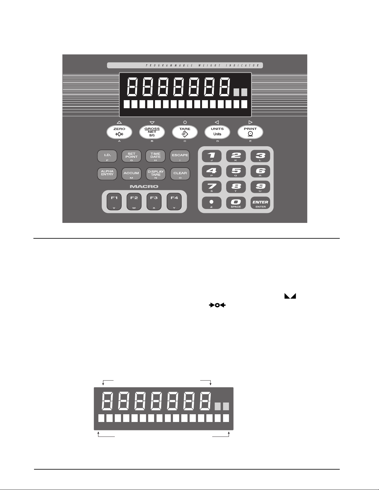
2
Figure 1-1. IQ plus 710 Front Panel
1.2 Front Panel Display
Figure 1-1 shows the IQ plus 710 front panel keys and
the key functions assigned in normal mode.
The IQ plus 710 display is divided into three areas
(see Figure 1-2):
• The primary display consists of seven large,
14-segment digits used to display weight data.
• A two-digit annunciator shows the units
associated with the displayed value: lb=pounds,
kg=kilograms, oz=ounces, T=short tons,
t=metric tons, LT=long tons, g=grams,
GN=grains. When the units configured are troy
troy
pounds or troy ounces, the word
the secondary display area in addition to the
oz
or
annunciator. The units can also be set to
NONE (no units information displayed).
PRIMARY DISPLAY
is shown in
lb
The two-digit annunciator also displays whether
the indicator is in numeric entry (NE) or alpha
entry (AE) mode for some operations.
The 16-digit secondary display is used to display the
weighing mode (Gross/Brutto or Net) and status
indicators, including standstill ( ) and center of
zero ( ).
The symbols shown over the keys in Figure 1-1
(representing up, down, enter, left, right) describe the
key functions assigned in setup mode. In setup mode,
the keys are used to navigate through menus, select
digits within numeric values, and increment/
decrement values. See Section 3.1.3 on page 14 for
information about using the front panel keys in setup
mode.
2-DIGIT
ANNUNCIATOR
for UNITS,
alpha entry (AE),
numeric entry (NE)
SECONDARY DISPLAY
Figure 1-2. IQ plus 710 Front Panel Display Areas
IQ plus 710 Installation Manual
Page 6

1.3 Indicator Operations
Basic IQ plus 710 operations are summarized below:
1.3.1 Toggle Gross/Net Mode
Press the
from gross to net, or from net to gross. If a tare value
has been entered or acquired, the net value is the gross
weight minus the tare. If no tare has been entered or
acquired, the display remains in gross mode.
Gross mode is indicated by the word
Brutto
indicated by the word
1.3.2 Toggle Units
Press the
secondary units. The units identifier is shown to the
right of the primary display. Troy ounces and troy
pounds are indicated by the word
secondary display.
1.3.3 Zero Scale
1.3.4 Acquire Tare
To display the current tare value, press the
TARE
1.3.5 Remove Stored Tare Value
1.3.6 Print Ticket
GROSS/NET
key to switch the display mode
Gross
(or
) on the secondary display; net mode is
Net
.
UNITS
key to switch between primary and
troy
on the
1. In gross mode, remove all weight from the
scale and wait for the standstill annunciator
().
ZERO
2. Press the
key. The center of zero
( ) annunciator lights to indicate the
scale is zeroed.
1. Place container on scale and wait for the
standstill annunciator ( ).
key to acquire the tare weight
2. Press the
TARE
of the container.
3. Display shifts to net weight and shows the
Net
word
on the secondary display.
DISPLAY
key.
1. Remove all weight from the scale and wait for
the standstill annunciator ( ).
2. Press the
weight and shows the word
ZERO
key. Display shifts to gross
Gross
on the
secondary display.
1. Wait for the standstill annunciator ( ).
2. Press the
PRINT
key to send data to the serial
port.
1.3.7 Display or Change Time and Date
To display the date, press the
TIME/DATE
press
a second time to display the time.
To set the date, press the
TIME/DATE
TIME/DATE
key once;
key once. Use
the numeric keypad to enter the date, then press the
ENTER
key. The date must be entered in the date
format configured for the indicator: MMDDYY or
DDMMYY .
To set the time, press the
TIME/DATE
key twice. Use
the numeric keypad to enter the time in 24-hour
format, then press the
1.3.8 Display or Change Setpoint Value
To display a setpoint value, press the
ENTER
key.
SETPOINT
key a
number of times equal to the setpoint number. For
example, to display the value of setpoint 4, press the
SETPOINT
key four times.
To change the setpoint value, display the current
value, then use the numeric keypad to enter the new
value and press the
NOTE:
Some indicator configurations may not allow
ENTER
key.
setpoint values to be changed through the front panel
or may require a password to display or change the
setpoint value.
1.3.9 Turn Setpoint On or Off
To turn a setpoint off at the front panel, press the
SETPOINT
key a number of times equal to the
setpoint number. With the correct setpoint displayed,
CLEAR
press
to turn the setpoint off.
To re-enable a setpoint on that has been turned off at
the front panel, press the
SETPOINT
correct setpoint is displayed, then press
key until the
ENTER
to turn
the setpoint back on.
NOTE:
Some indicator configurations may not allow
setpoints to be turned off through the front panel or
may require a password to turn the setpoint on and off.
1.3.10 Display or Clear Accumulator
If the accumulator function is enabled, the current net
weight is added to the accumulator each time the
indicator performs a print operation.
• To display the current accumulator value,
press the
• To clear the accumulator, press
ACCUM
key.
ACCUM
to
show the current value, then press the CLEAR
key twice to reset the accumulator.
Introduction
3
Page 7

2.0 Installation
This section describes procedures for connecting load
cells, digital I/O, and serial communications cables to
the IQ plus 710 indicator. Instructions for field
installation of the analog output option and
replacement of the CPU board are included, along
with assembly drawings and parts lists for the service
technician.
Caution
• Use a wrist strap to ground yourself and protect
components from electrostatic discharge (ESD)
when working inside the indicator enclosure.
• This unit uses double pole/neutral fusing which
could create an electric shock hazard. Procedures
requiring work inside the indicator must be
performed by qualified service personnel only.
• The supply cord serves as the power disconnect for
the IQ plus 710. The power outlet supplying the
indicator must be installed near the unit and be
easily accessible.
2.1 Unpacking and Assembly
Immediately after unpacking, visually inspect the IQ
plus 710 to ensure all components are included and
undamaged. The shipping carton should contain the
indicator with attached tilt stand, this manual, and a
parts kit. If any parts were damaged in shipment,
notify Rice Lake Weighing Systems and the shipper
immediately.
The parts kit contains the items listed below:
• Capacity and identification labels.
• Two 8-32NC x 7/16 fillister head screws (PN
30623). These screws occupy the holes above
and on either side of the setup screw on the
indicator backplate (see Figure 2-2 on page
7).
• Ten 8-32NC x 3/8 machine screws (PN
14862) for the indicator backplate (see #29 in
Figure 2-6 on page 12).
• Twelve bonded sealing washers (PN 45042)
for backplate screws included in the parts kit.
• Four cord grip reducing glands (PN 15664).
• Four rubber bumpers (“feet”) for the tilt stand,
PN 42149.
• 6 cable ties, PN 15631.
2.2 Enclosure Disassembly
The indicator enclosure must be opened to connect
cables for load cells, communications, digital inputs,
digital outputs, and analog output.
The IQ plus 710 has no on/off switch.
Warning
Before opening the unit, ensure the
power cord is disconnected from the
power outlet.
Ensure power to the indicator is disconnected, then
place the indicator face-down on an antistatic work
mat. Remove the screws that hold the backplate to the
enclosure body, then lift the backplate away from the
enclosure and set it aside.
2.3 Cable Connections
The IQ plus 710 provides five cord grips for cabling
into the indicator: one for the power cord, four to
accommodate load cell, communications, digital I/O,
and analog output cables. Three of the four free cord
grips come with a plug installed to prevent moisture
from entering the enclosure. Depending on your
application, remove the plug from any cord grip that
will be used and install cables as required.
4 IQ plus 710 Installation Manual
Page 8
+20 mA
–20 mA
Prn RxD
Prn TxD
EDP RxD
GND
EDP TxD
GND
RS485-B
RS485-A
GND
+5V
J12
J4
+I
–I
7
6
5
4
3
2
SERIAL COMMUNICATIONS - 1
1
7
C79
6
5
C83
4
R32
3
C88
2
R33
SERIAL COMMUNICATIONS - 2
1
C92
U23
BROWN WIRE
J1
J9
B1
R34
C90
+
U15
R37
R36
C103
TO LINE FILTER
–SIG
+SIG
LOAD CELL CONNECTOR
R5
R4
C19
R14
C39
C40
JP3
C91
R35
R38
C100
+
C104
P2
F2F1
BLUE WIRE
JP1
C41
Q1
R21
C49
C50
C71
U7
4
3
2
1
+EXC
–EXC
SHIELD
–SENSE
+SENSE
7654321
D1
C1
D2
JP2
R6
C20
J15
R20
U3
C51
U8
R28
R29
U11
C89
LOCATION OF INSTALLED ANALOG OUTPUT MODULE
J1
C94
+
C2
SW1
D4
D9
C11
C21
C22
C42
R7
R8
R16
R15
C54
C55
C56
J6
C95
D5
7
6
R10
R9
R17
R18
C58
C57
KEYPAD CONNECTOR
RN7
+
D6
8
L2
L1
C43
C44
C52
C53
C72
C80
R26
R27
R30
U17
T1
14
15
1
2
3
4
5
6
7
DIGITAL INPUT
8
9
10
C87
J7
GND
DI1
DI2
DI3
DI4
DI5
DI6
DI7
DI8
GND
C8
C9
R1
C4
C5
C3
C12
C13
C23
C59
R2
C14
RN1
U1
C25
C24
C61
C63
C62
C60
C65
C64
J10
1
RN8
RN9
R3
C7
C6
C15
D3
U2
C16
R11
R12
C27
C26
C28
R19
+
+
J5
C10
C18
RN2
C17
C29
Y1
C66
C73
C81
U12
R13
C36
C38
C35
C32
C31
C33
C30
C34
U4
R22
U5
U9
R24
R23
U6
C78
R31
C84
U13
C86
C37
RN3
RN4
C47
C48
C45
C46
C70
C67
C69
C68
RN6
RN5
C77
C76
C75
C74
R25
U10
C82
C85
U14
ANALOG OUTPUT
C93
U16
EPROM
C96
U18
D8
R40
D7
9
1011
3
12
JP4
C97
C101
U19
50
51
R42
R41
C106
75
C105
C107
R44
Y3
R48
R47
RN13
R52
U26
D13
D12
D14
D11
C112
C113
C115
C114
26
25
U22
76
1
100
RN11
RN12
C108
RN14
D10
U27
D16
D17
D18
D15
RN15
C119
C117
C118
C116
C98
C99
U20
U21
RN10
R39
R43
C102
12
U24
Y2
34
C109
R45
Q2
R50
R46
R49
U25
C110
C111
R51
R54
R53
U28
RN16
DIGITAL OUTPUT
7654321
9
8
10
+5V
DO8
DO7
DO6
DO5
DO4
DO3
DO2
DO1
J8
GND
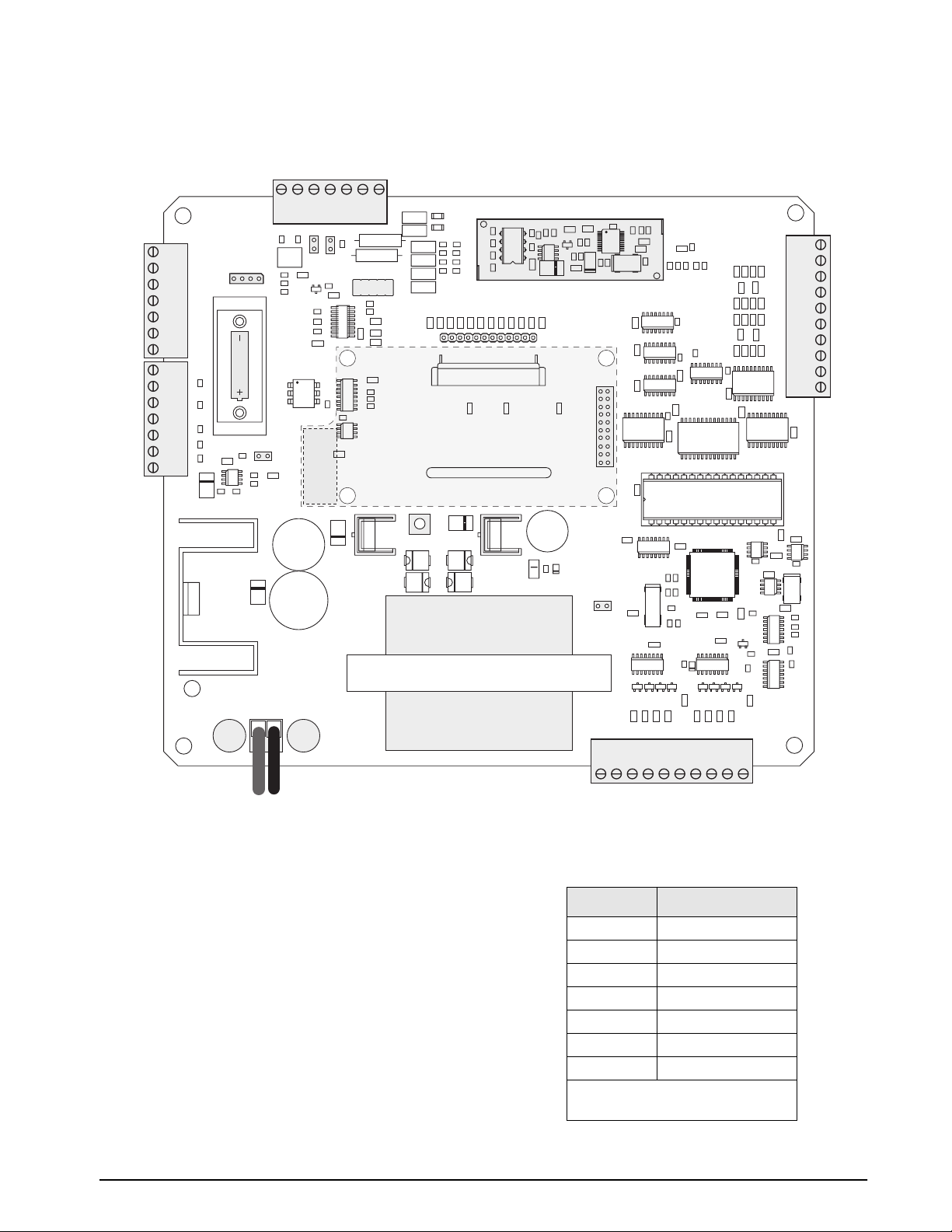
Figure 2-1. IQ plus 710 CPU and Power Supply Board, Rev. 2
2.3.1 Load Cells
To attach cable from a load cell or junction box,
remove connector J1 from the board. The connector
plugs into a header on the board (see Figure 2-1).
Wire the load cell cable from the load cell or junction
box to connector J1 as shown in Table 2-1. If using
6-wire load cell cable (with sense wires), remove
jumpers JP1 and JP2 before reinstalling connector J1
(see Figure 2-1). For 4-wire installation, leave
jumpers JP1 and JP2 on.
When connections are complete, reinstall connector
J1 on the board and use two cable ties to secure the
load cell cable to the inside of the enclosure.
J1 Pin Function
1 +SIG
2 –SIG
3 +SENSE
4 –SENSE
5 SHIELD
6 +EXC
7 –EXC
For 6-wire load cell connections,
remove jumpers JP1 and JP2.
Table 2-1. J1 Pin Assignments
Installation 5
Page 9
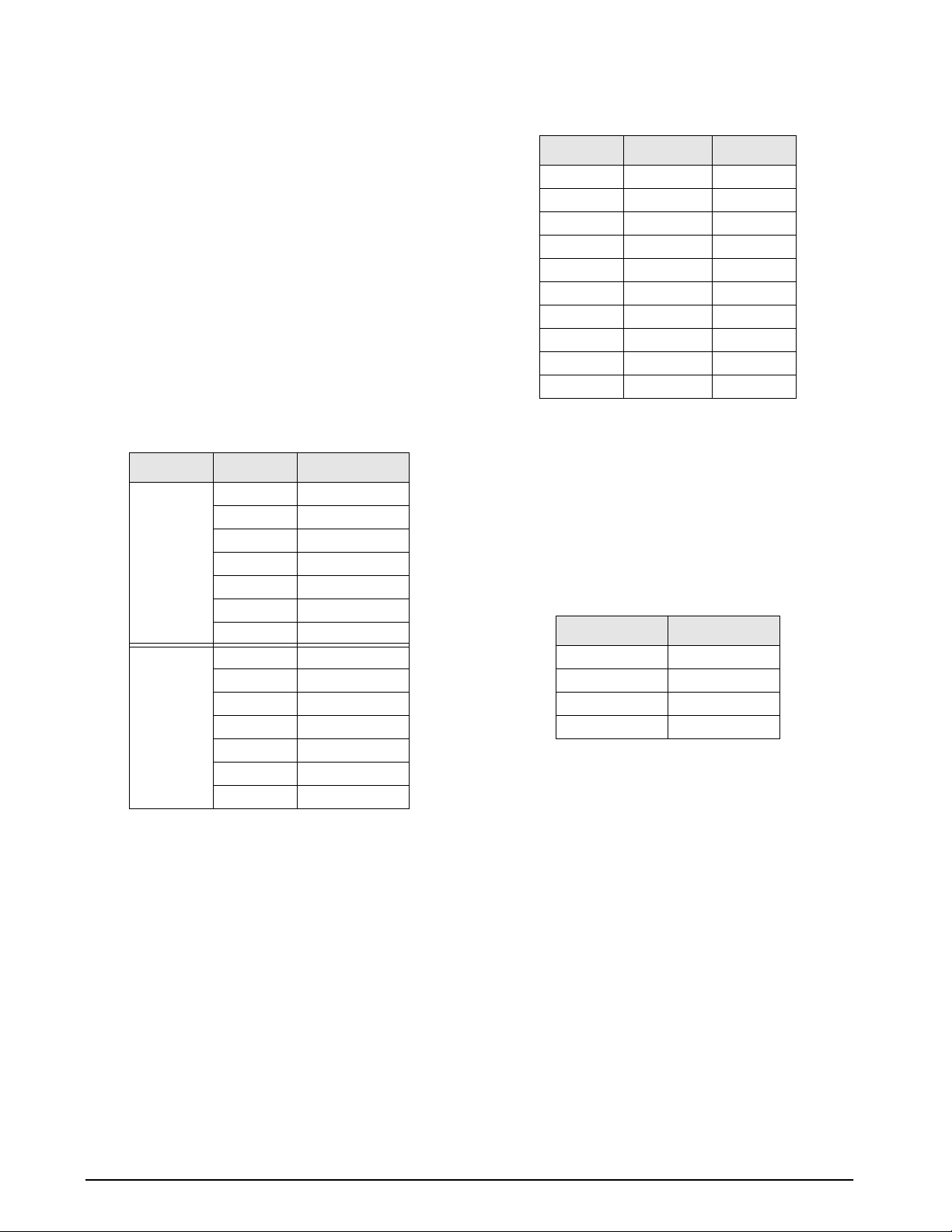
2.3.2 Serial Communications
To attach serial communications cables, remove
connector J4 or J12 from the board. Connector J4
provides connections for the EDP (Electronic Data
Processing) port, printer port, and 20 mA current loop
transmit signals; connector J12 provides RS-485 and
20 mA current loop receive signals. Table 2-2 shows
the pin assignments for connectors J12 and J4.
Once cables are attached, reconnect J12 or J4 to the
header on the board. Use cable ties to secure serial
cables to the inside of the enclosure.
The EDP port supports RS-232 or RS-485
communications; the printer port provides active 20
mA output and RS-232 transmission. Both ports are
configured using the SERIAL menu. See Section 3.0
on page 13 for configuration information.
Connector Pin Signal
J4
J12
Table 2-2. J4 and J12 Pin Assignments
2.3.3 Digital I/O
1 EDP TxD
2 GND
3 EDP RxD
4 Printer TxD
5 Printer RxD
6 –20 mA TxD
7 +20 mA TxD
1 –I (–20 mA RxD)
2 +I (+20 mA RxD)
3 +5V
4 GND
5 RS485-A
6 RS485-B
7 GND
Digital inputs can be set to provide several indicator
functions, including all keypad functions. The inputs
are active (on) with low voltage (0 VDC) and can be
driven by TTL or 5V logic without additional
hardware. Use the DIG IN menu to configure the
digital inputs.
Digital outputs are typically used to drive relays that
control other equipment. Up to eight relays can be
mounted inside the flat front enclosure; up to four
relays can be mounted inside the sloped front
enclosure. Use the SETPNTS menu to configure
digital outputs.
Table 2-3 shows the pin assignments for connectors J7
and J8.
Pin J7 Signal J8 Signal
1 GND GND
2 DI1 DO1
3 DI2 DO2
4 DI3 DO3
5 DI4 DO4
6 DI5 DO5
7 DI6 DO6
8 DI7 DO7
9 DI8 DO8
10 GND +5V
Table 2-3. J7 and J8 Pin Assignments (Digital I/O)
2.3.4 Analog Output
If the optional analog output module is installed,
attach the output cable to connector J1 on the analog
output board. Table 2-4 lists the analog output pin
assignments.
Use the ALGOUT menu to configure and calibrate the
analog output module when cabling is complete. See
Section 2.4 for information about installing the analog
output module.
Pin Signal
1 + Current Out
2 – Current Out
3 + Voltage Out
4 – Voltage Out
Table 2-4. Analog Output Module Pin Assignments
2.4 Analog Output Module Installation
To install or replace the analog output module, follow
the steps listed in Section 2.2 on page 4 for opening
the IQ plus 710 enclosure.
Mount the analog output module on its standoffs in
the location shown in Figure 2-1 on page 5 and plug
the module input into connector J5 on the IQ plus 710
board. Connect the output cable to the analog output
module as shown in Table 2-4, then reassemble the
enclosure (Section 2.5).
See Section 10.7 on page 69 for analog output
calibration procedures.
6 IQ plus 710 Installation Manual
Page 10
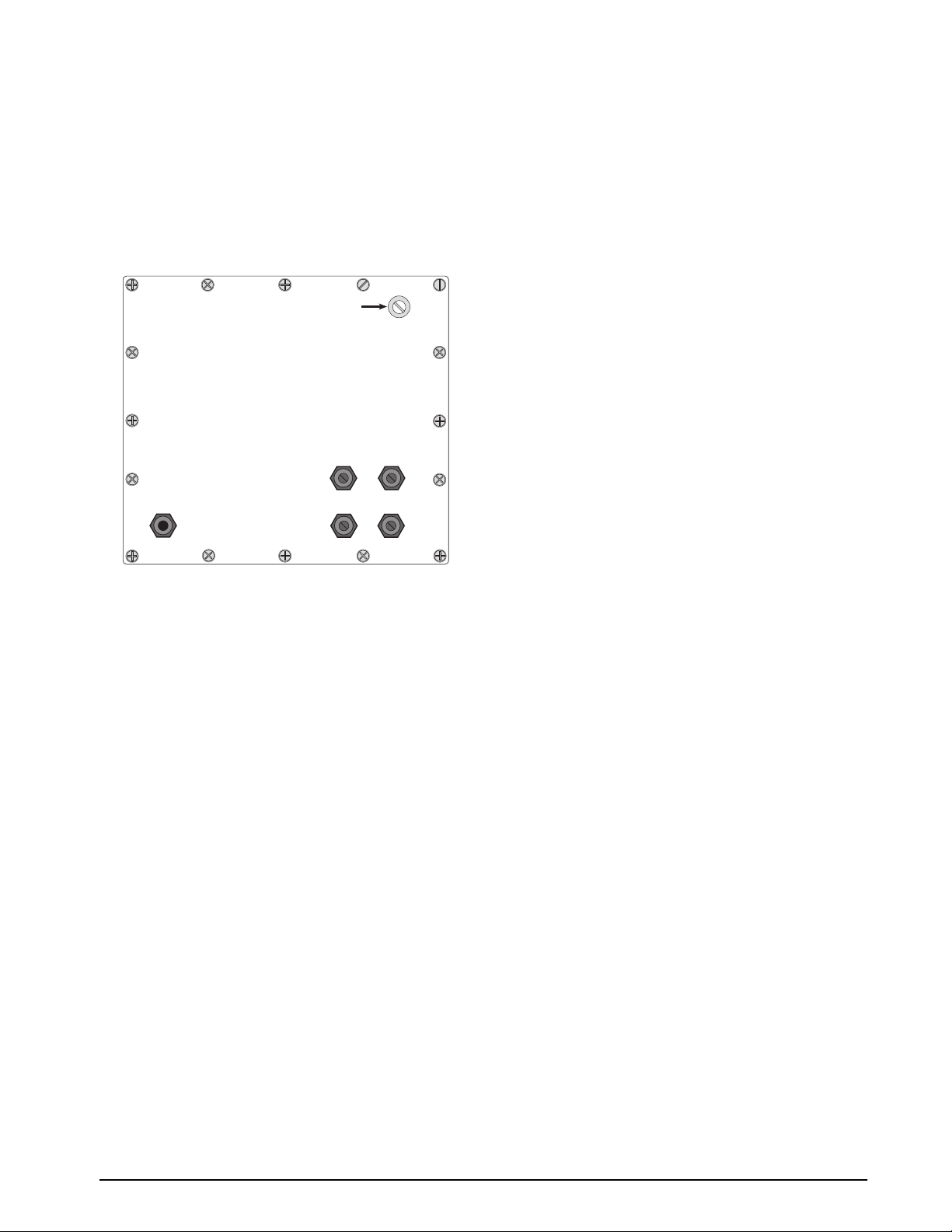
2.5 Enclosure Reassembly
Once cabling is complete, position the backplate over
the enclosure and reinstall the backplate screws. Use
the torque pattern shown in Figure 2-2 to prevent
distorting the backplate gasket. Torque screws to 10
in-lb (1.13 N-m).
15
11
1
5
9
Setup switch access screw
Torque backplate screws
to 10 in-lb (1.13 N-m)
7
13
Fillister head screws
4
12
6
16
2.7 Battery Replacement
The 3.0V lithium battery on the power supply/display
board maintains the real-time clock and protects data
stored in the system RAM when the indicator is not
connected to AC power.
System RAM data includes time and date, print
formats, truck ID storage, and setpoint configuration.
This information is lost if the battery loses power and
the indicator is disconnected from AC power. To
prevent loss of data, do the following:
• Periodically check the battery voltage and
replace when the voltage drops. The battery
should last a minimum of one year.
• Use the Revolution configuration utility or
EDP commands (see Section 5.2 on page 44)
to store a copy of the indicator configuration
on a PC before attempting battery
replacement. If any data is lost, the indicator
configuration can be restored from the PC.
14
Figure 2-2. IQ plus 710 Enclosure Backplate
8
10
23
2.6 Board Removal
If you must remove the IQ plus 710 CPU board, use
the following procedure:
1. Disconnect power to the indicator. Loosen
cord grips and remove backplate as described
in Section 2.2 on page 4.
2. Unplug connectors J1 (load cell cable), J4 and
J12 (serial communications), J7 and J8
(digital I/O), J6 (keypad ribbon cable), and
JP4 (setup switch). If an analog output board
is installed, disconnect the analog output
cable. See Figure 2-1 on page 5 for connector
locations.
3. Remove the standoff and three nuts from the
corners of the CPU board.
4. Cut the cable tie that holds the line filter load
wires to the enclosure.
5. Lift the board off of its spacers just far enough
to access the setscrews that secure the line
filter load wires at connector P2. Use a small
screwdriver to loosen the setscrews and
disconnect power to the board.
6. Remove the CPU board from the enclosure.
To replace the CPU board, reverse the above
procedure. Be sure to reinstall cable ties to secure all
cables inside the indicator enclosure.
Installation 7
Page 11
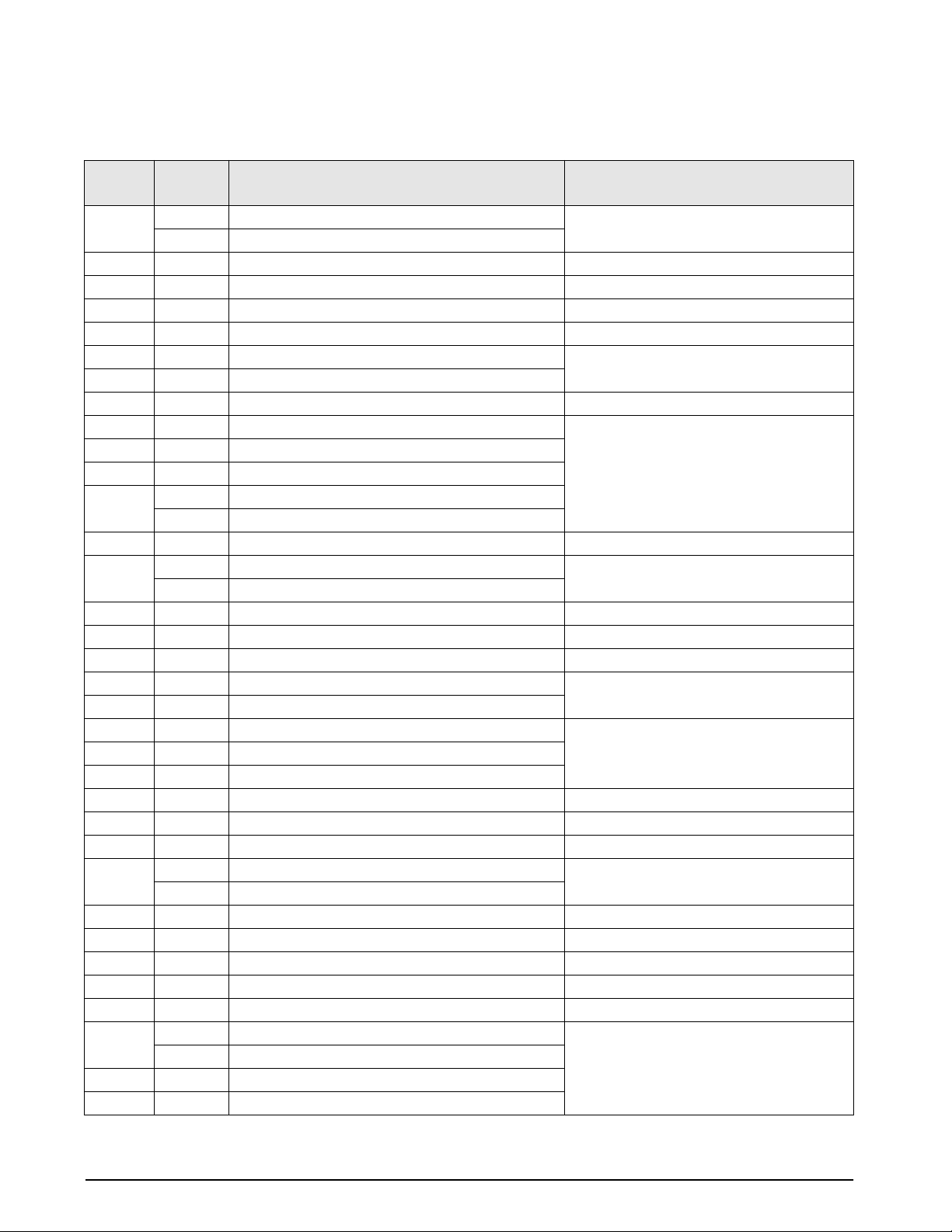
2.8 Replacement Parts
Table 2-5 lists replacement parts for the IQ plus 710, including all parts referenced in Figures 2-3 through 2-7.
Ref
Number
1 41397 Enclosure, sloped front (1) Figure 2-6 on page 12
2 41398 Enclosure backplate (1) Figure 2-3 on page 9
3 14626 Kep nuts, 8-32NC hex (13) Figure 2-6 on page 12
4 30375 Nylon seal rings for cable grips (4) Figure 2-3 on page 9
5 14621 Kep nuts, 6-32NC hex (4–flat enclosure; 6–sloped) Figure 2-5 on page 11
6 15626 Cable grips, PG9 (4) Figure 2-3 on page 9
7 15627 Locknuts, PCN9 (4)
8 15650* Cable tie mounts (8) Figure 2-4 on page 10
10 19538 Cable grip plugs (3) Figure 2-3 on page 9
11 44676 Sealing washer for setup switch access screw (1)
12 42640 Setup switch access screw, 1/4 x 28NF x 1/4 (1)
13 41965 Power cord assembly, 115VAC (1)
15 16892 Ground/Earth label (1) Figure 2-4 on page 10
16 45402 Bezel, sloped front (1) Figure 2-6 on page 12
17 41386 Switch panel membrane (1) Figure 2-6 on page 12
18 41400 Backplate gasket (1) Figure 2-3 on page 9
19 45043 Ground wire, 4 in w/ No. 8 eye connector (1) Figure 2-4 on page 10
21 46027 Setup switch mounting bracket (1) Figure 2-5 on page 11
24 44844 Setup switch assembly (1)
25 30342 Wing knobs for tilt stand (2) Figure 2-7 on page 12
26 29635 Tilt stand (1)
27 15144 Nylon washers for tilt stand, 1/4 x 1 x 1/16 (2)
28 45891 Line filter assembly (1) Figure 2-4 on page 10
29 14862* Screws, 8-32NC x 3/8 (4) Figure 2-7 on page 12
30 16903 Model/serial number label (1) —
31 46252 Bezel gasket, sloped front (1) Figure 2-6 on page 12
36 45401 CPU board mounting tab, sloped front models (1) Figure 2-5 on page 11
37 15134 Lock washers, No. 8 (4) Figure 2-4 on page 10
38 48027 Nylon spacers for board mounting (4) Figure 2-5 on page 11
39 45042* Sealing washers (4) Figure 2-7 on page 12
40 15369 Standoffs, fem 6-32NC x 3/4 (3) Figure 2-4 on page 10
41 44541 Display and CPU board assembly, Rev 2, 115 VAC (1) Figure 2-5 on page 11
— 40698 VFD display (1)
42 19644 3V cylindrical lithium battery
PN Description (Quantity) Figure
41401 Enclosure, flat front (1)
45254 Power cord assembly, 230VAC (1)
41399 Bezel, flat front (1)
45076 Bezel gasket, flat front (1)
44540 Display and CPU board assembly, Rev 2, 230 VAC (1)
8 IQ plus 710 Installation Manual
Table 2-5. Replacement Parts
Page 12
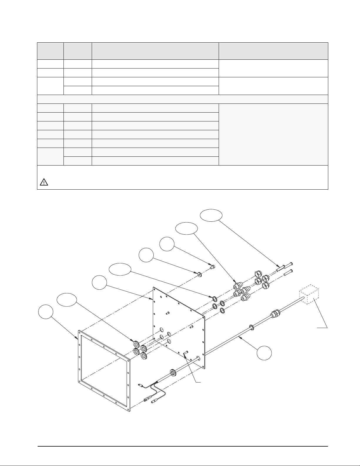
Ref
Number
— 42104 7-position connectors for J1, J4, and J12 (3) Figure 2-1 on page 5
— 46420 10-position connectors for J7 and J8 (2)
— 45484 160 mA TR5 subminiature fuses (2), 115 VAC F1 and F2 in Figure 2-1 on page 5
The following parts apply only to units using the Rev 1 CPU board with cable interface board
9 14839 Machine screw, 6-32NC x 1/4 (4) Not shown
20 45312 Interface board assembly (1)
24 45414 Serial cable, interface board to CPU board (1)
32 45388 Interface board mounting bracket, top (1)
33 45387 Interface board mounting bracket, side (1)
— 46444 315 mA TR5 subminiature fuses (2), 115 VAC
* Additional parts included in parts kit.
Caution
PN Description (Quantity) Figure
45107 80 mA TR5 subminiature fuses (2), 230 VAC
46445 160 mA TR5 subminiature fuses (2), 230 VAC
To protect against the risk of fire, replace fuses only with same type and rating fuse.
See Section 10.11 on page 72 for complete fuse specifications.
Table 2-5. Replacement Parts (Continued)
10/3X
18
6/4X
12
11
4/4X
2
7/4X
115V/ 230V PLUG
13
BACKPLATE GROUND STUD
Figure 2-3. Backplate Assembly
Installation 9
Page 13
B
37/4X
TO BACKPLATE
GROUND STUD
POWER CORD
CABLE TIE
28
19
C
8/6X/D
D
15
BROWN
BLUE
TO CPU BOARD P2
D
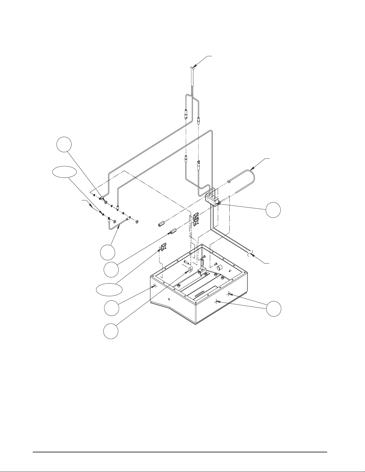
Figure 2-4. Enclosure and Line Filter Assembly
10 IQ plus 710 Installation Manual
Page 14
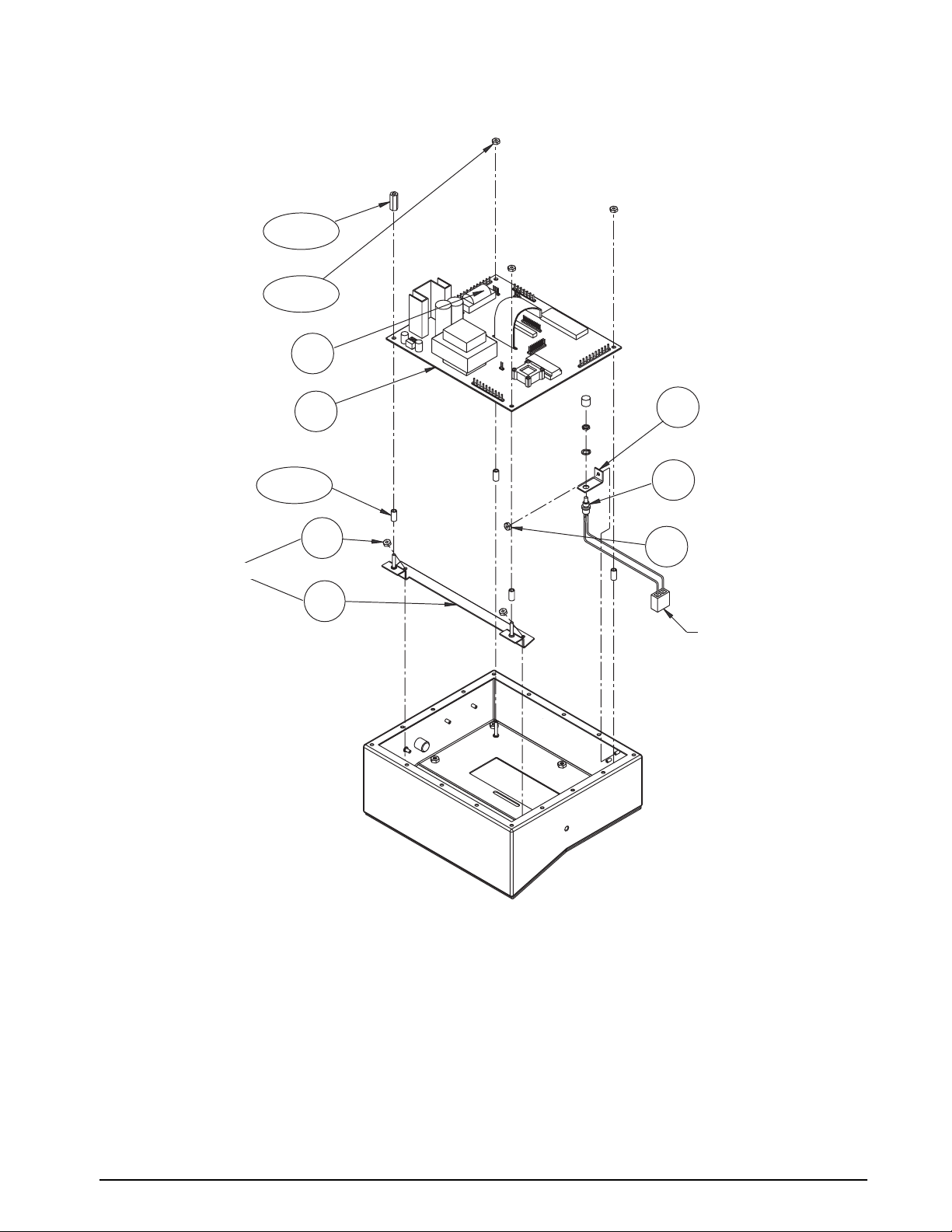
40/3X/C
5/6X/A
42
41
38/4X
A
SLOPED FRONT MODELS ONLY
36
21
24
A
TO JUMPER JP4
Figure 2-5. Enclosure and CPU Board Assembly
Installation 11
Page 15
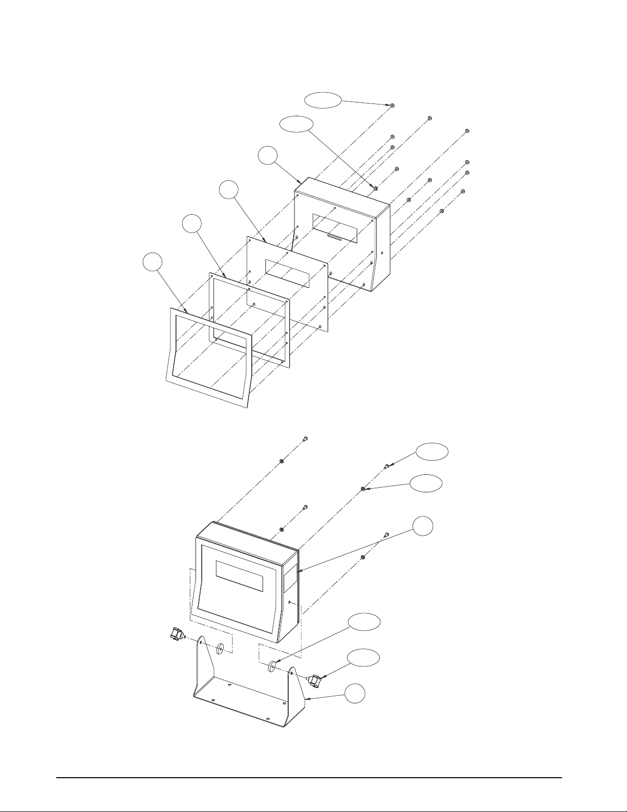
16
3/13X/B
44/3X
1
17
31
Figure 2-6. Bezel Assembly
27/2X
25/2X
26
29/4X
39/4X
30
12 IQ plus 710 Installation Manual
Figure 2-7. Tilt Stand Assembly
Page 16
3.0 Configuration
To configure the IQ plus 710 indicator, the indicator
must be placed in setup mode. The setup switch is
accessed by removing the large fillister head screw on
the enclosure backplate. Switch position is changed
by inserting a screwdriver into the access hole and
pressing the switch.
When the indicator is placed in setup mode, the word
CONFIG is shown on the display. The CONFIG menu
is the first of ten main menus used to configure the
indicator. Detailed descriptions of these menus are
given in Section 3.2. When configuration is complete,
return to the CONFIG menu and press the (
ZERO)
key to exit setup mode, then replace the setup switch
access screw.
3.1 Configuration Methods
The IQ plus 710 indicator can be configured by using
the front panel keys to navigate through a series of
configuration menus or by sending commands or
configuration data to the EDP port. Configuration
using the menus is described in Section 3.1.3.
Configuration using the EDP port can be
accomplished using either the EDP command set
described in Section 5.0 or the Revolution
configuration utility.
3.1.1 Revolution Configuration
The Revolution configuration utility provides the
preferred method for configuring the IQ plus 710
indicator. Revolution runs on a personal computer to
set configuration parameters for the indicator. When
Revolution configuration is complete, configuration
data is downloaded to the indicator.
™
Revolution supports both uploading and downloading
of indicator configuration data. This capability allows
configuration data to be retrieved from one indicator,
edited, then downloaded to another.
To use Revolution, do the following:
1. Install Revolution on an IBM-compatible
®
personal computer running Windows
3.11 or
Windows 95. Minimum system requirements
are 4MB of extended memory and at least
5MB of available hard disk space.
2. With both indicator and PC powered off,
connect the PC serial port to the RS-232 pins
on the indicator EDP port.
3. Power up the PC and the indicator. Use the
setup switch to place the indicator in setup
mode.
4. Start the Revolution program.
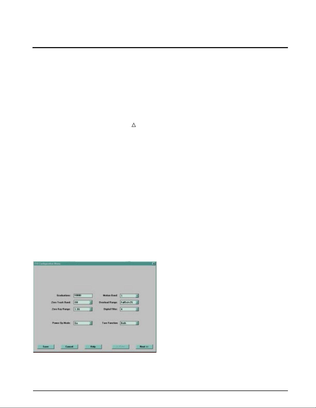
Figure 3-1 shows an example of one of the Revolution
configuration displays.
Revolution provides online help for each of its
configuration displays. Parameter descriptions
provided in this manual for front panel configuration
can also be used when configuring the indicator using
Revolution: the interface is different, but the
parameters set are the same.
3.1.2 EDP Command Configuration
The EDP command set can be used to configure the
IQ plus 710 indicator using either a personal
computer, terminal, or remote keyboard. Like
Revolution, EDP command configuration sends
commands to the indicator EDP port; unlike
Revolution, EDP commands can be sent using any
external device capable of sending ASCII characters
over a serial connection.
EDP commands duplicate the functions available
using the indicator front panel and provide some
functions not otherwise available. EDP commands can
be used to simulate pressing front panel keys, to
configure the indicator, or to dump lists of parameter
settings. See Section 5.0 on page 37 for more
information about using the EDP command set.
Figure 3-1. Sample Revolution Configuration Display
Configuration 13
Page 17
3.1.3 Front Panel Configuration
The IQ plus 710 indicator can be configured using a series of menus accessed through the indicator front panel
when the indicator is in setup mode. Table 3-1 summarizes the functions of each of the main menus.
Menu Menu Function
CONFIG Configuration Configure grads, zero tracking, zero range, motion band, overload, tare function, power-up
mode, and digital filtering parameters.
FORMAT Format Set format of primary and secondary units, decimal format, and display rate.
CALIBR Calibration Calibrate indicator. See Section 4.0 on page 33 for calibration procedures.
SERIAL Serial Configure EDP and printer serial ports.
PROGRM Program Set date and time formats, truck mode, passwords, keyboard locks, regulatory mode, and
initial consecutive number value; enable accumulator; define macro prompts and program
macros.
PFORMT Print Format Set print format used for header, gross, net, truck in/out, setpoint, and EDP format tickets. See
Section 6.0 for more information.
SETPNTS Setpoints Configure setpoints, batching mode, and assign setpoint names.
DIG IN Digital Input Assign digital input functions.
ALGOUT Analog Output Configure analog output module. Used only if analog output option is installed.
VERSION Version Display installed software version number.
Table 3-1. IQ plus 710 Menu Summary
ZERO
Move UP /
Increment Value
GROSS
NET
B/G
TARE
UNITS
Units
ENTER Value
Move DOWN /
Decrement Value
Move LEFT /
Previous
SETUP MODE 5-KEY FUNCTIONS
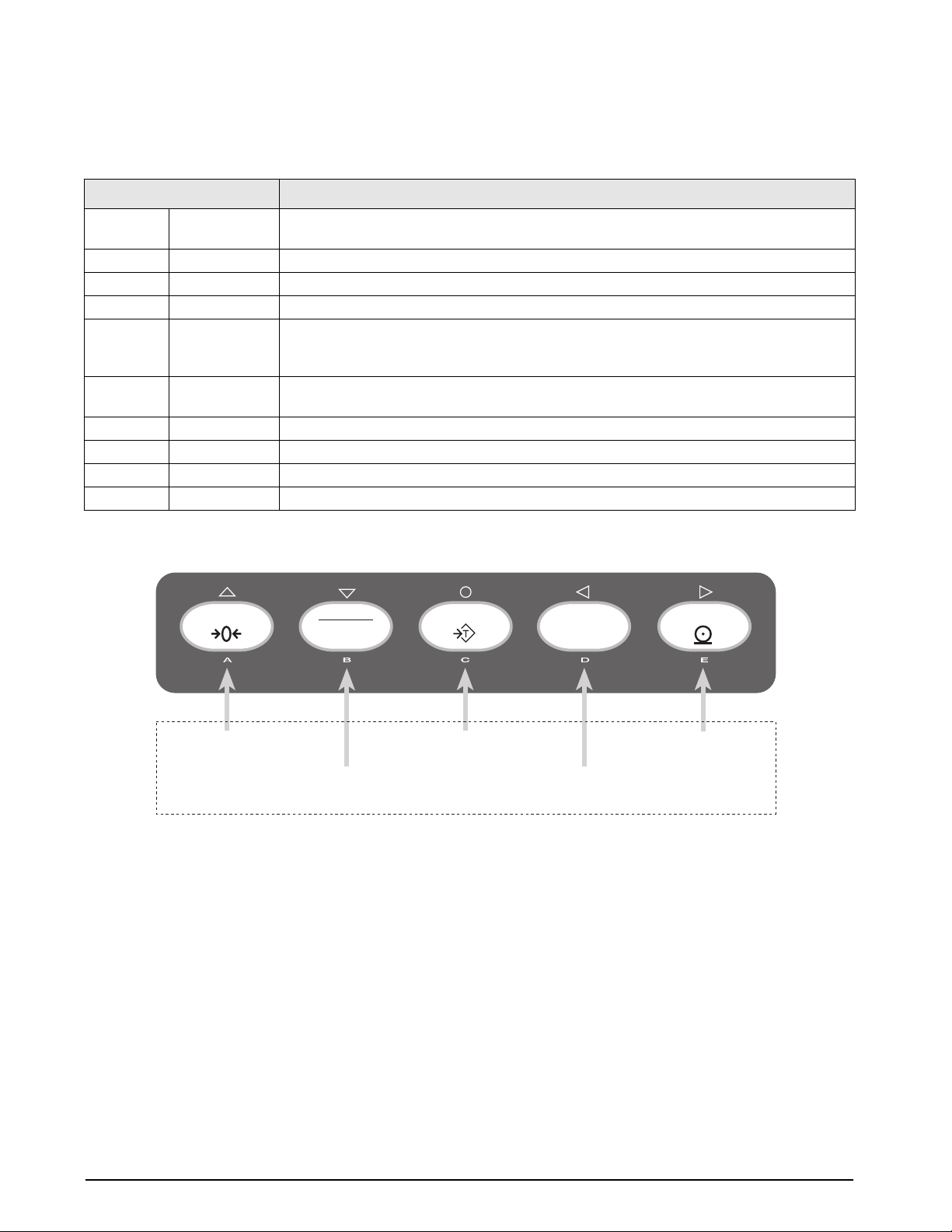
Figure 3-2. Five-Key Keypad Functions in Setup Mode
PRINT
Move RIGHT /
Next
14 IQ plus 710 Installation Manual
Page 18
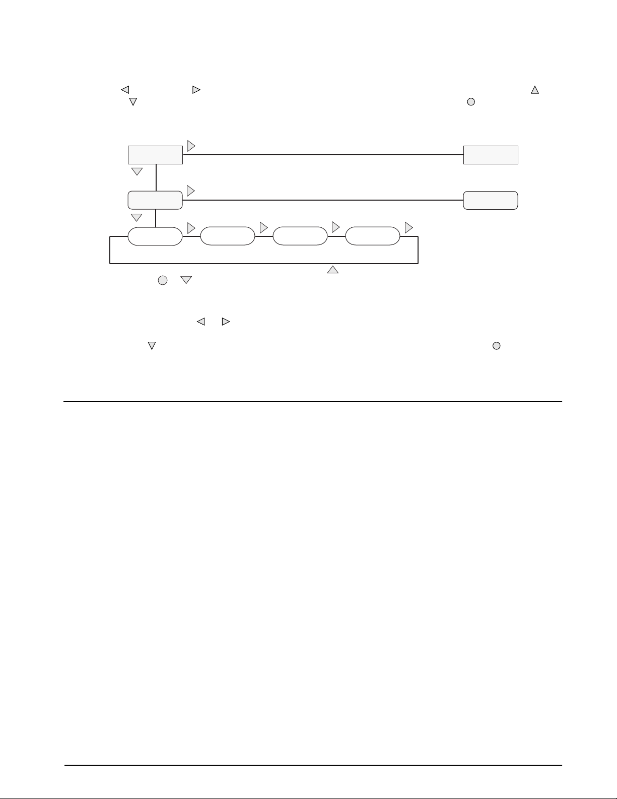
Four front panel keys are used as directional keys to navigate through the menus in setup mode (see Figure 3-2).
UNITS ( ) and PRINT ( ) keys scroll left and right (horizontally) on the same menu level; ZERO ( ) and
The
GROSS/NET ( ) move up and down (vertically) to different menu levels. The TARE key ( ) serves as an Enter
key for selecting parameter values within the menus. A label over each of these keys identifies the direction
provided by the key when navigating through the setup menus.
1st Level
Parameter
2nd Level
Parameter
Default value
When moving through values below the first menu level, press to return to the level
above. Press or to move to the next parameter on the level above.
Value Value Value
Figure 3-3. Setup Mode Menu Navigation
To select a parameter, press or to scroll left or
right until the desired menu group appears on the
display , then press to move down to the submenu or
parameter you want. When moving through the menu
parameters, the default or previously selected value
appears first on the display.
To change a parameter value, scroll left or right to
view the values for that parameter. When the desired
value appears on the display, press to select the
value and move back up one level. To edit numerical
values, use the numeric keypad on the indicator front
panel.
1st Level
Parameter
2nd Level
Parameter
3.2 Menu Structures and Parameter Descriptions
The following sections provide graphic representations of the IQ plus 710 menu structures. In the actual menu
structure, the settings you choose under each parameter are arranged horizontally. To save page space, menu
choices are shown in vertical columns. The factory default setting appears at the top of each column. Parameters
shown surrounded by a dotted-line box only appear under the special circumstances explained under each box.
Most menu diagrams are accompanied by one or more tables that describe all parameters and parameter values
associated with that menu option. Default parameter values are shown in bold type.
Configuration 15
Page 19
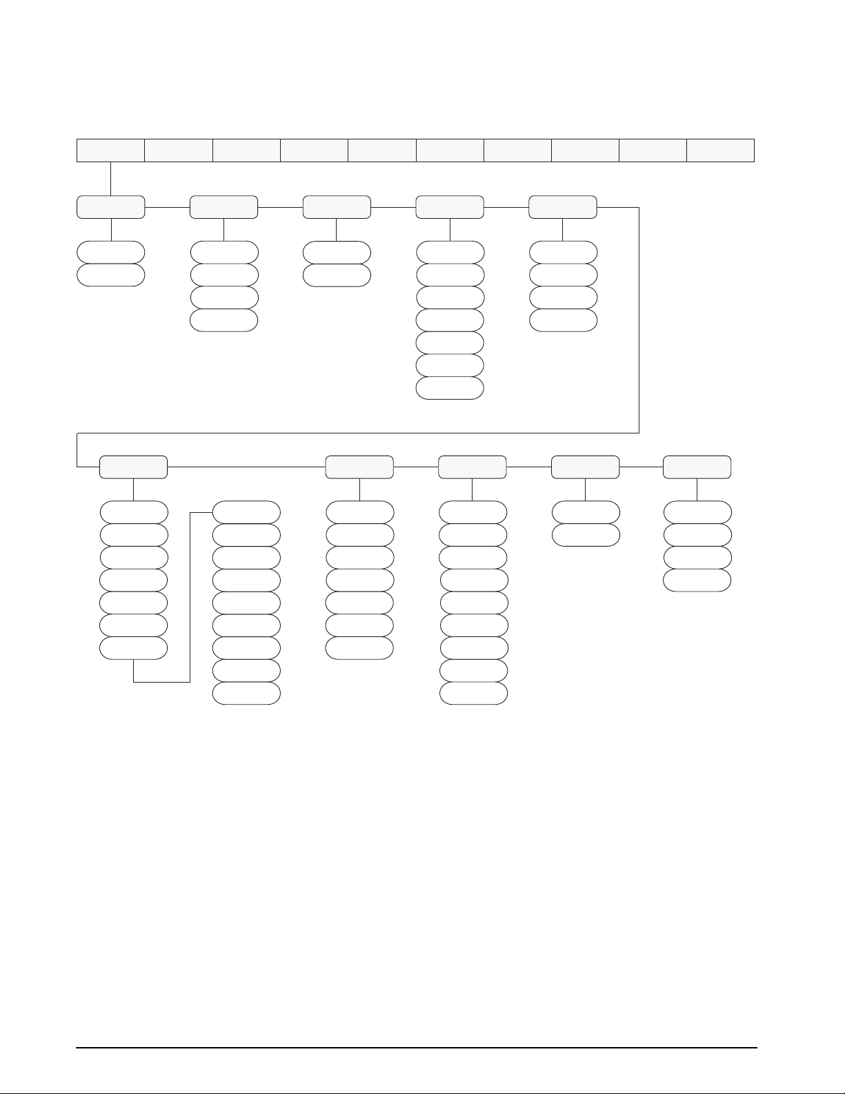
3.2.1 Configuration Menu
GRADS
10000
number
DIGFLTR
8
16
32
64
128
256
XXXXXXX XXXXXXXXXXXXXXXXXXXXX
ZTRKBND ZRANGE
OFF
0.5D
1D
3D
4
4RT
8RT
16RT
32RT
64RT
128RT
256RT
1
2
1.9%
100%
DFSENS DFTHRH
8OUT
16OUT
32OUT
64OUT
128OUT
2OUT
4OUT
MOTBAND
1D
2D
3D
5D
10D
20D
OFF
NONE
2DD
5DD
10DD
20DD
50DD
100DD
200DD
250DD
OVRLOAD
FS+2%
FS+1D
FS+9D
FS
PWRUPMD
GO
DELAY
ALGOUTDIG INSETPNTSPROGRM PFORMTSERIALCALIBRCONFIG FORMAT
VERS
TAREFN
BOTH
NOTARE
PBTARE
KEYED
16 IQ plus 710 Installation Manual
Figure 3-4. Configuration Menu
Page 20

CONFIG Menu
Parameter Choices Description
Level 2 submenus
GRADS 10000
number
ZTRKBND OFF
0.5D
1D
3D
ZRANGE 1.9%
100%
MOTBAND 1D
2D
3D
5D
10D
20D
OFF
OVRLOAD FS+2%
FS+1D
FS+9D
FS
DIGFLTR 4
8
16
32
64
128
256
4RT
8RT
16RT
32RT
64RT
128RT
256RT
1
2
DFSENS 8OUT
16OUT
32OUT
64OUT
128OUT
2OUT
4OUT
Specifies the number of full scale graduations. The value entered must be in the range
1–100000 and should be consistent with legal requirements and environmental limits on
system resolution.
To calculate GRADS, use the formula, GRADS = Capacity / Display Divisions.
Display divisions for primary and secondary units are specified on the FORMAT menu.
Automatically zeroes the scale when within the range specified, as long as the input is
within the ZRANGE and scale is at standstill. Selections are ± display divisions. Maximum
legal value varies depending on local regulations.
Selects the range within which the scale can be zeroed. The 1.9% selection is ± 1.9%
around the calibrated zero point, for a total range of 3.8%. Indicator must be at standstill to
zero the scale. Use 1.9% for legal-for-trade applications.
Sets the level, in display divisions, at which scale motion is detected. If motion is not
detected for 1 second or more, the standstill symbol lights. Some operations, including
print, tare, and zero, require the scale to be at standstill. Maximum legal value varies
depending on local regulations.
If this parameter is set to OFF, the standstill annunciator will not light; operations normally
requiring standstill (zero, tare, print) are performed regardless of scale motion. If OFF is
selected, ZTRKBND must also be set to OFF.
Determines the point at which the display blanks and an out-of-range error message is
displayed. Maximum legal value varies depending on local regulations.
Selects the digital filtering rate used to reduce the effects of mechanical vibration from the
immediate area of the scale.
Choices indicate the number of A/D conversions per update that are averaged to obtain the
displayed reading. A higher number gives a more accurate display by minimizing the effect
of a few noisy readings, but slows down the settling rate of the indicator.
Digital filter cutout sensitivity. Specifies the number of consecutive readings that must fall
outside the filter threshold (DFTHRH parameter) before digital filtering is suspended.
Table 3-2. Configuration Menu Parameters
Configuration 17
Page 21

CONFIG Menu
Parameter Choices Description
DFTHRH NONE
2DD
5DD
10DD
20DD
50DD
100DD
200DD
250DD
PWRUPMD GO
DELAY
TAREFN BOTH
NOTARE
PBTARE
KEYED
Digital filter cutout threshold. Specifies the filter threshold, in display divisions. When a
specified number of consecutive scale readings (DFSENS parameter) fall outside of this
threshold, digital filtering is suspended. If NONE is selected, the filter is always enabled.
Power up mode. In GO mode, the indicator goes into operation immediately after a brief
power up display test.
In DELAY mode, the indicator performs a power up display test, then enters a 30-second
warm up period. If no motion is detected during the warm up period, the indicator becomes
operational when the warm up period ends; if motion is detected, the delay timer is reset
and the warm up period repeated.
Enables or disables push-button and keyed tares. Possible values are:
BOTH: Both push-button and keyed tares are enabled
NOTARE: No tare allowed (gross mode only)
PBTARE: Push-button tares enabled
KEYED: Keyed tare enabled
Table 3-2. Configuration Menu Parameters (Continued)
18 IQ plus 710 Installation Manual
Page 22
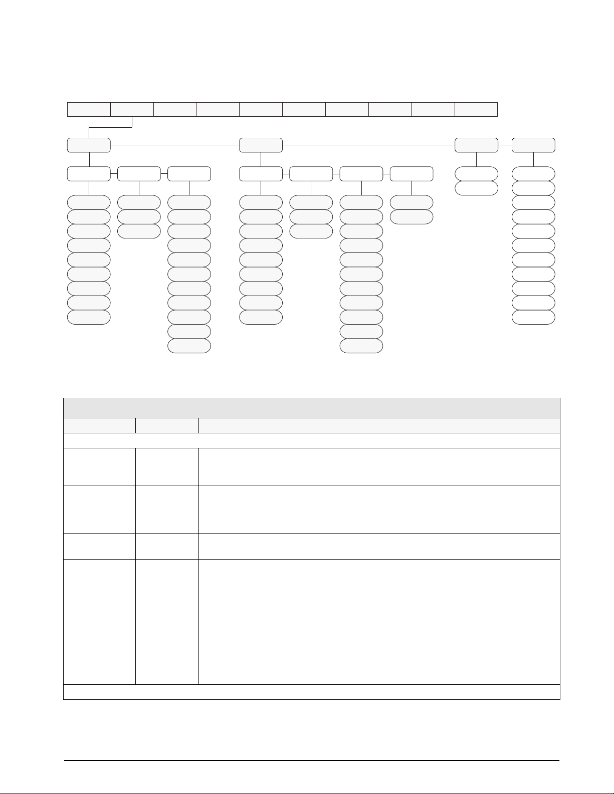
3.2.2 Format Menu
PRIMAR SECNDR
DSPDIV UNITSDECPNT
8888888
8888800
8.888888
88.88888
888.8888
8888.888
88888.88
888888.8
1D
2D
5D
LB
KG8888880
G
OZ
TN
T
GN
TROYOZ
TROYLB
LT
NONE
888888.8
8888888
8888880
8888800
8.888888
88.88888
888.8888
8888.888
88888.88
Figure 3-5. Format Menu
XXXXXXX XXXXXXXXXXXXXXXXXXXXX
DSPDIV MULTUNITSDECPNT
5D
1D
2D
KG
G
OZ
TN
T
GN
TROYOZ
TROYLB
LT
NONE
LB
ALGOUTDIG INSETPNTSPROGRM PFORMTSERIALCALIBRCONFIG FORMAT
0.453592
number
VERS
DECFMT
DOT
COMMA
DSPRATE
250MS
500MS
750MS
1SEC
1500MS
2SEC
2500MS
3SEC
4SEC
6SEC
8SEC
FORMAT Menu
Parameter Choices Description
Level 2 submenus
PRIMAR DECPNT
DSPDIV
UNITS
SECNDR DECPNT
DSPDIV
UNITS
MULT
DECFMT DOT
COMMA
DSPRATE 250MS
500MS
750MS
1SEC
1500MS
2SEC
2500MS
3SEC
4SEC
6SEC
8SEC
Level 3 submenus
Specifies the decimal position, display divisions, and units used for the primary units. See
Level 3 submenu parameter descriptions.
Specifies the decimal position, display divisions, units, and conversion multiplier used for the
secondary units. See Level 3 submenu parameter descriptions.
Specifies whether decimal numbers are displayed using a period (DOT) or comma as the
decimal symbol.
Display rate. Sets the update rate for displayed values. Values are in milliseconds (MS) or
seconds (SEC).
Table 3-3. Format Menu Parameters
Configuration 19
Page 23

FORMAT Menu
Parameter Choices Description
Primary Units (PRIMAR Parameter)
DECPNT 8888888
8888880
8888800
8.888888
88.88888
888.8888
8888.888
88888.88
888888.8
DSPDIV 1D
2D
5D
UNITS LB
KG
G
OZ
TN
T
GN
TROYOZ
TROYLB
LT
NONE
Secondary Units (SECNDR Parameter)
DECPNT 888888.8
8888888
8888880
8888800
8.888888
88.88888
888.8888
8888.888
88888.88
DSPDIV 5D
1D
2D
UNITS KG
G
OZ
TN
T
GN
TROYOZ
TROYLB
LT
NONE
LB
MULT 0.453592
Enter other
choices via
keyboard
Decimal point location. Specifies the location of the decimal point or dummy zeroes in the
primary unit display. Value should be consistent with local legal requirements.
Display divisions. Selects the minimum division size for the primary units displayed weight.
Specifies primary units for displayed and printed weight. Values are: LB=pound;
KG=kilogram; G=gram; OZ=ounce; TN=short ton; T=metric ton; GN=grain; TROYOZ=troy
ounce; TROYLB=troy pound; LT=long ton.
NOTE: Indicators sold outside North America are configured with KG for both primary and
secondary units.
Decimal point location. Determines the location of the decimal point or dummy zeros in the
display.
Display divisions. Selects the value of minimum division size of the displayed weight.
Specifies primary units for displayed and printed weight. Values are: LB=pound;
KG=kilogram; G=gram; OZ=ounce; TN=short ton; T=metric ton; GN=grain; TROYOZ=troy
ounce; TROYLB=troy pound; LT=long ton.
Multiplier. Specifies the conversion factor by which the primary units are multiplied by to
obtain the secondary units. The default is 0.453592, which is the conversion factor for
changing pounds to kilograms. See Section 10.6 on page 67 for a list of multipliers.
To toggle between primary and secondary units, press the UNITS key.
20 IQ plus 710 Installation Manual
Table 3-3. Format Menu Parameters (Continued)
Page 24
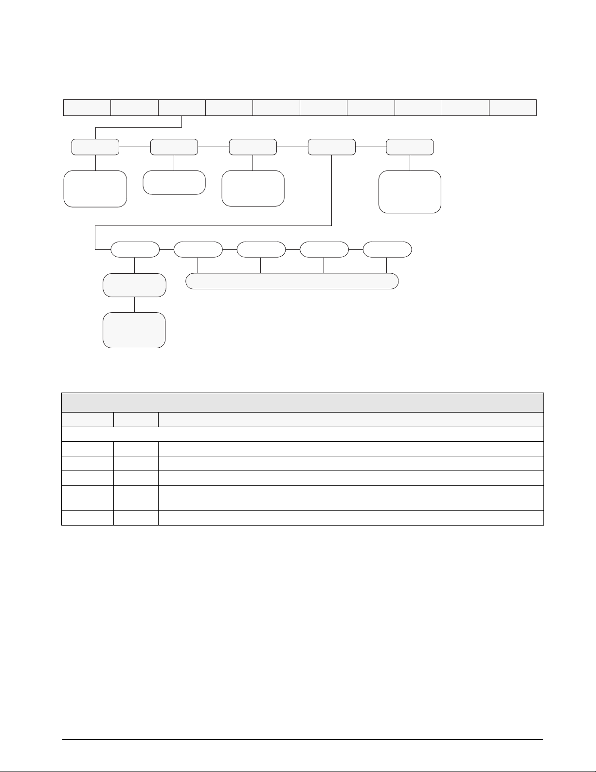
3.2.3 Calibration Menu
See Section 4.0 on page 33 for calibration procedures.
WZERO
*CALIB*
Display and edit
zero calibration
A/D count value
Display and edit
test weight value
Display and edit
linearization point
A/D count value
PT–> 1
*CALIB*
WVAL
Display and edit
test weight value
PT–> 2 PT–> 3 PT–> 4 PT–> 5
WSPAN
*CALIB*
Display and edit
span calibration
A/D count value
Same as PT-> 1
Figure 3-6. Calibration Menu
XXXXXXX XXXXXXXXXXXXXXXXXXXXX
REZEROWLIN
*CALIB*
Press Enter to
remove offset from
zero and span
calibrations
ALGOUTDIGINSETPNTSPROGRM PFORMTSERIALCALIBRCONFIG FORMAT
VERS
CALIBR Menu
Parameter Choices Description
Level 2 submenus
WZERO — Display and edit the zero calibration A/D count value.
WVAL — Display and edit the test weight value.
WSPAN — Display and edit the span calibration A/D count value.
WLIN PT->1 —
Display and edit test weight and calibration values for up to five linearization points.
PT->5
REZERO — Press Enter to remove an offset value from the zero and span calibrations.
Table 3-4. Calibration Menu Parameters
Configuration 21
Page 25
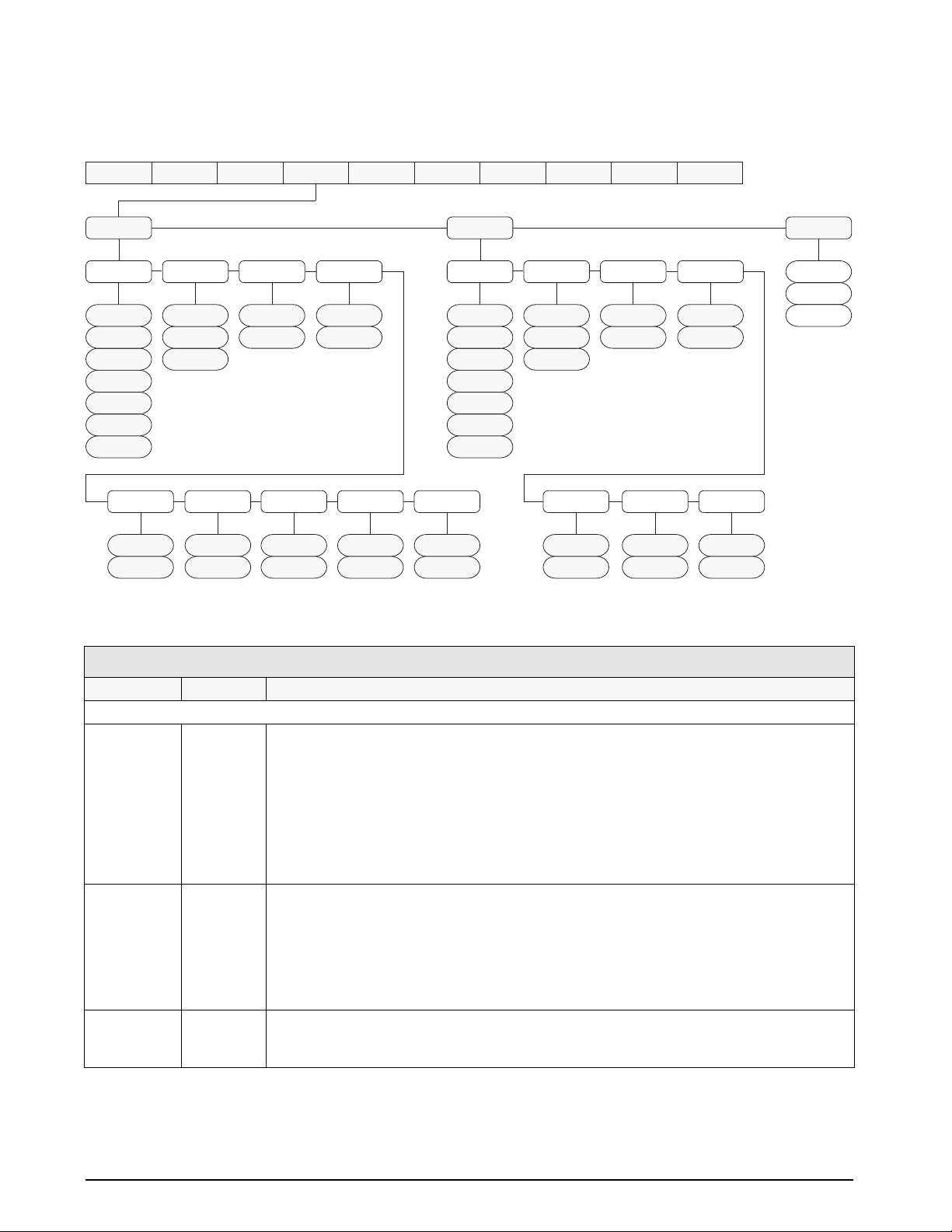
3.2.4 Serial Menu
See Section 10.3 on page 64 for information about IQ plus 710 serial data formats.
SERIALCALIBRCONFIG FORMAT
EDP PRINT
OFF
ON
EOLDLY
0
number
STREAMADDRESS
OFF
ON
9600
19200
300
600
1200
2400
4800
HANDSHK
OFF
ON
BITS TERMINBAUD
8NONE
7EVEN
7ODD
number
CR/LF
CR
AB-RIO
0
PFORMT
9600
19200
300
600
1200
2400
4800
PORT
MAIN
AUX
Figure 3-7. Serial Menu
SETPNTS
DIG INPROGRM
XXXXXXX XXXXXXXXXXXXXXXXXXXXX
BITS TERMINBAUD
8NONE
7EVEN
7ODD
HANDSHK
OFF
ON
ALGOUT
CR/LF
CR
STREAM
OFF
ON
VERS
EOLDLY
0
number
PORT
RS232
20MA
PRNDEST
EDP
PRN
BOTH
SERIAL Menu
Parameter Choices Description
Level 2 submenus
EDP BAUD
Configure the EDP port. See Level 3 submenu parameter descriptions.
BITS
TERMIN
EOLDLY
HANDSHK
ADDRESS
AB-RIO
STREAM
PORT
PRINT BAUD
Configure the printer port. See Level 3 submenu parameter descriptions.
BITS
TERMIN
EOLDLY
HANDSHK
STREAM
PORT
PRNDEST EDP
PRN
Print destination. Selects the port for data transmission when the PRINT key is pressed or the
KPRINT EDP command is sent.
BOTH
Table 3-5. Serial Menu Parameters
22 IQ plus 710 Installation Manual
Page 26

SERIAL Menu
Parameter Choices Description
Level 3 Submenus EDP Port
BAUD 9600
19200
300
600
1200
2400
4800
BITS 8NONE
7EVEN
7ODD
TERMIN CR/LF
CR
EOLDLY 0
number
HANDSHK OFF
ON
ADDRESS 0
address
AB-RIO OFF
ON
STREAM OFF
ON
PORT MAIN
AUX
Level 3 Submenus Printer Port
BAUD 9600
19200
300
600
1200
2400
4800
BITS 8NONE
7EVEN
7ODD
TERMIN CR/LF
CR
EOLDLY 0
number
HANDSHK OFF
ON
STREAM OFF
ON
PORT RS232
20MA
Baud rate. Selects the transmission speed for the EDP port.
Selects number of data bits and parity of data transmitted from the EDP port.
Termination character. Selects termination character for data sent from the EDP port.
End-of-line delay. Sets the delay period, in 0.1-second intervals, from when a formatted line is
terminated to the beginning of the next formatted serial output. Value specified must be in the
range 0-255, in tenths of a second (10 = 1 second).
Specifies whether XON/XOFF flow control characters are used.
Specifies the decimal indicator address for RS-485 connections. RS-232 communications is
disabled if an address other than zero is specified for this parameter. RS-485 addresses must be
in the range 01–255.
Specifies whether the EDP uses the Allen-Bradley Remote I/O data stream. Specify ON only if
the Remote I/O option is installed.
Specifies whether data is streamed from the EDP port.
Reserved for future use.
Baud rate. Selects the transmission speed for the printer port.
Selects number of data bits and parity of data transmitted from the printer port.
Termination character. Selects termination character for data sent from the printer port.
End-of-line delay. Sets the delay period, in 0.1-second intervals, from when a formatted line is
terminated to the beginning of the next formatted serial output. Value specified must be in the
range 0-255, in tenths of a second (10 = 1 second).
Specifies whether XON/XOFF flow control characters are used.
Specifies whether data is streamed from the printer port.
Reserved for future use.
Table 3-5. Serial Menu Parameters (Continued)
Configuration 23
Page 27
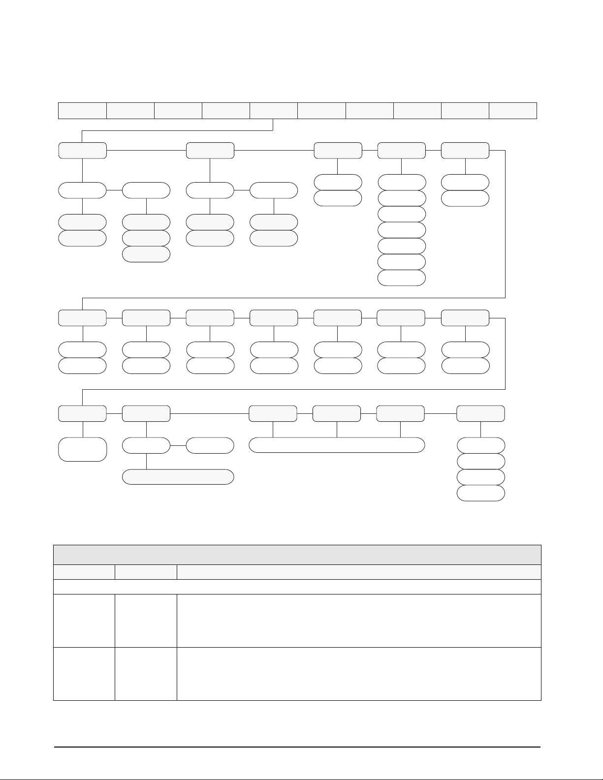
3.2.5 Program Menu
DATE
DATEFMT
MMDDYY
DDMMYY
CFGPWD
0
number
DATESEP
SLASH
DASH
SEMI
SPPWD
0
number
TIME
TIMEFMT
12HOUR
24HOUR
KYBDLK
OFF
ON
TIMESEP
COLON
COMMA
AUXLK
OFF
ON
CONSTUP
0
number
MACONLY
OFF
ON
SETPNTS ALGOUTDIG INPROGRM PFORMTSERIALCALIBRCONFIG FORMAT
TARE100
OFF
MODE1
MODE2
MODE3
MODE4
MODE5
MODE6
ZERONLY
OFF
ON
XXXXXXX
ACCUM
OFF
ON
ALPHAKB
OFF
ON
VERS
PROMPTS
PROMPT1–
PROMPT60
MACRO1
EDIT STRTBAT
Edit macro
MACRO2 MACRO3 MACRO4
same as MACRO1
Figure 3-8. Program Menu
PROGRM Menu
Parameter Choices Description
Level 2 submenus
DATE DATEFMT
DATESEP
TIME TIMEFMT
TIMESEP
Allows selection of date format and date separator character. See Level 3 submenu parameter
descriptions.
Use the TIME/DATE key or the SD EDP command to set the date. See Section 5.0 on
page 37 for information about using the EDP commands.
Allows selection of time format and separator character. See Level 3 submenu parameter
descriptions.
Use the TIME/DATE key or the ST EDP command to set the time. See Section 5.0 on
page 37 for information about using the EDP commands.
REGULAT
NTEP
CANADA
NONE
OIML
24 IQ plus 710 Installation Manual
Table 3-6. Program Menu Parameters
Page 28

PROGRM Menu
Parameter Choices Description
CONSTUP 0
number
TARE100 OFF
MODE1
MODE2
MODE3
MODE4
MODE5
MODE6
ACCUM OFF
ON
CFGPWD 0
1–9999999
SPPWD 0
1–9999999
KYBDLK OFF
ON
AUXLK OFF
ON
MACONLY OFF
ON
ZERONLY OFF
ON
ALPHAKB OFF
ON
PROMPTS PROMPT1–
PROMPT60
MACRO1
MACRO2
MACRO3
MACRO4
REGULAT NTEP
Level 3 submenus
DATEFMT MMDDYY
DATESEP SLASH
TIMEFMT 12HOUR
TIMESEP COLON
STRTBAT
EDIT
OIML
NONE
CANADA
DDMMYY
DASH
SEMI
24HOUR
COMMA
Specifies the initial consecutive number value used when the indicator is reset. Value specified
must be in the range 0–9 999 999.
Specifies the truck mode used. If selected, the indicator switches from normal mode to the
selected truck mode. See Section 7.0 on page 49 for more information about using the truck
modes.
MODE1: Auto clear ID, keyed tares, value swapping
MODE2: Auto clear ID, no keyed tares, value swapping
MODE3: Stored ID, keyed tares, value swapping
MODE4: Stored ID, no keyed tares, value swapping
MODE5: Stored ID, keyed tares, no value swapping
MODE6: Stored ID, no keyed tares, no value swapping
Accumulator. Specifies whether the accumulator is enabled.
Configuration password. Specify a non-zero value to restrict access to all configuration
menus.
Setpoint password. Specify a non-zero value to restrict access to the setpoint menu.
Keyboard lock. Specify ON to disable the keypad in normal mode.
Auxiliary keypad lock. Specify ON to disable all keys except ZERO, GROSS/NET, TARE,
UNITS, and PRINT in normal mode.
Macro keys only. Specify ON to disable all except the four macro keys (F1–F4) in normal mode.
Zero key only. Specify ON to disable all front panel keys except ZERO in normal mode.
Alpha keyboard. Specify ON to enable alpha entry for the indicator keypad. If OFF is specified,
the ALPHA ENTRY key is disabled.
Specify prompts for use in macros. Prompts are r efer enced by the NAME parameter under the
MACRO submenu; prompts appear in the secondary display area during macro execution.
Specify MACROs 1–4. The STRBAT parameter can be set on to start a batch sequence on
completion of the macro; the EDIT parameter contains up to 30 macro steps, including
simulated keystrokes and pause/release conditions. See Section 9.0 on page 55 for more
information about configuring macros.
Regulatory mode. Specifies the regulatory agency having jurisdiction over the scale site.
NONE allows entry of a zero tare, enabling use of net mode by batch routines.
OIML and CANADA modes require the scale load to be at zero before clearing a tare; OIML
mode replaces the
Specifies the format used to display or print the date.
Specifies the date separator character.
Specifies the format used to display or print the time.
Specifies the time separator character.
Gross annunciator with Brutto.
Table 3-6. Program Menu Parameters (Continued)
Configuration 25
Page 29
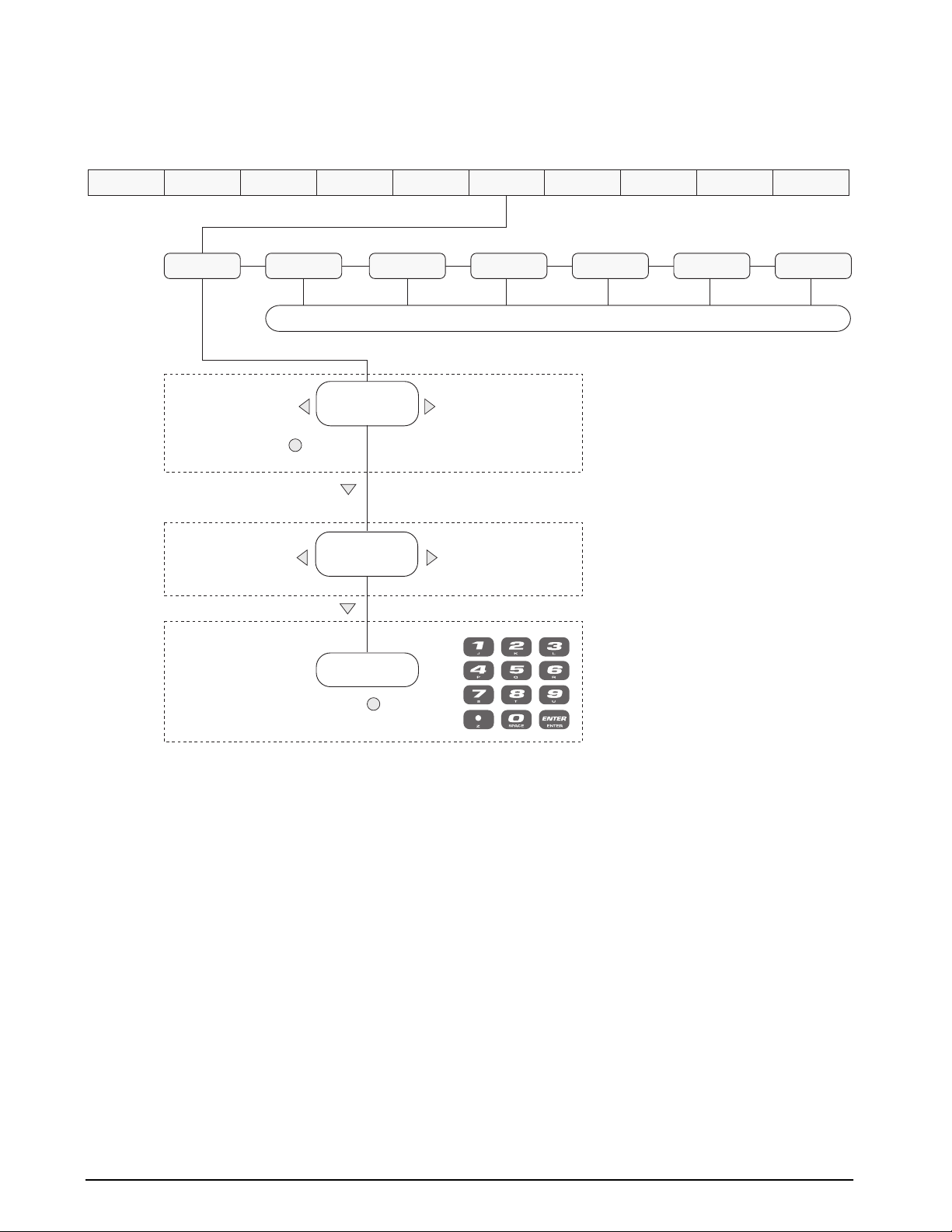
3.2.6 Print Format Menu
See Section 6.0 on page 45 for information about custom print formatting.
GFMT
Press ENTER or to insert a
space before the active character
Decrement ASCII value
of active character
NFMT
characters of format
active character and
TRWIN
Display first 7
Press CLEAR to delete
the active character
Display and edit
ASCII value
Same as GFMT
Scroll right in format stringScroll left in format string
Increment ASCII value
of active character
DIG INSETPNTSPROGRM PFORMTSERIALCALIBRCONFIG FORMAT
XXXXXXXXXXXXXX
SPFMTTRWOUT
ALGOUT
EDPFMT
VERS
HDRFMT
Enter numeric ASCII
character value
Press ENTER or to save value
Figure 3-9. Print Format Menu
26 IQ plus 710 Installation Manual
Page 30
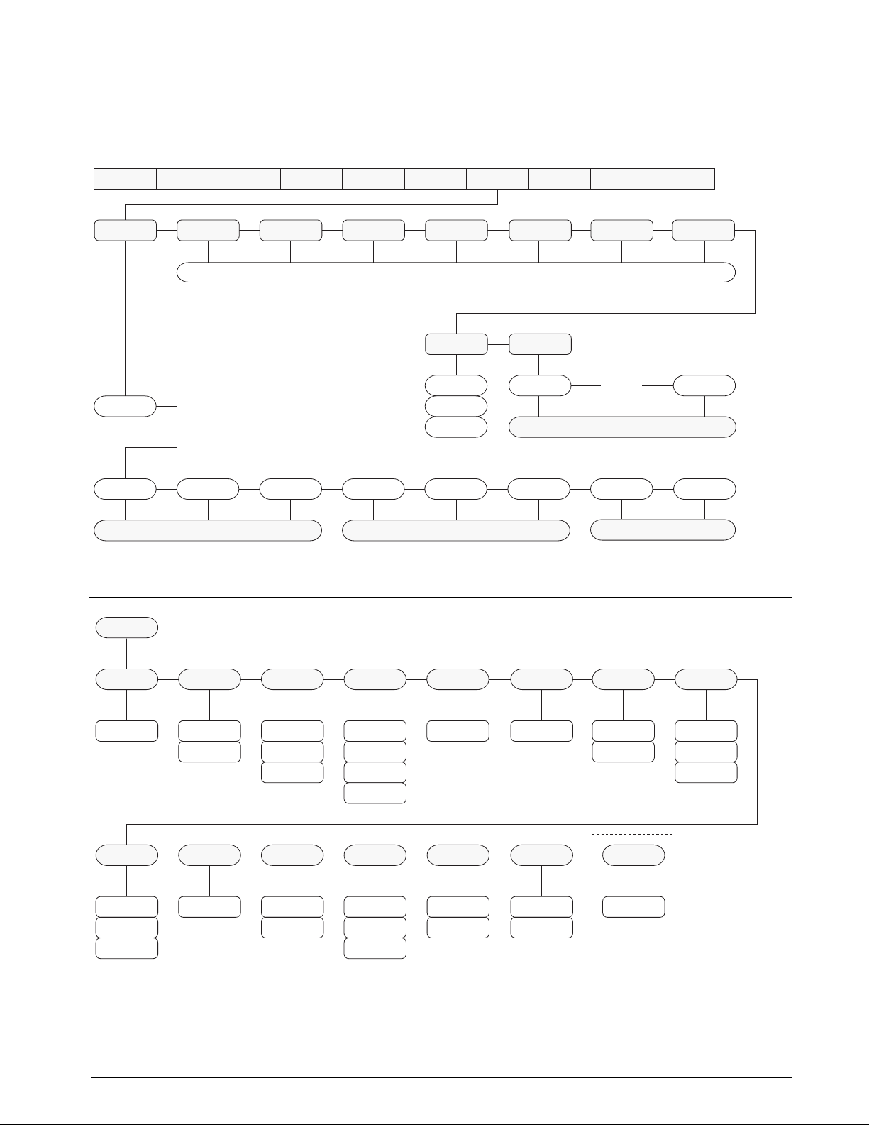
3.2.7 Setpoints Menu
See Section 8.0 on page 51 for more information about configuring and using setpoints.
SETPT1
OFF
GROSSSP NETSP –RELSP
SETPT2 SETPT3 SETPT4 SETPT5 SETPT6 SETPT7 SETPT8
Go to A Go to B
SETPNTS ALGOUTDIG INPROGRM PFORMTSERIALCALIBRCONFIG FORMAT
Same as SETPT1
BATCHNG
OFF
AUTO
MANUAL
PAUSE DELAY WAITSS TIMER CONCUR
SPNAMES
NAME1 NAME16
XXXXXXX
…
setpoint name
VERS
Go to C
Figure 3-10. Setpoints Menu
A
VALUE
number
PREACT
OFF
ON
LEARN
GROSSSP, NETSP, and –RELSP Setpoints
PSHTARE
OFF
ON
PREVAL
number
PSHPRNT
OFF
ON
WAITSS
BATCH
OFF
ON
TRIP
HIGHER
LOWER
INBAND
OUTBAND
ACCESS
OFF
ON
HIDE
Figure 3-11. Submenu for GROSSSP, NETSP, and –RELSP Setpoints
BANDVAL
number
NAME
NONE
1–16
HYSTER
number
DIGOUT
NONE
1–8
ALARM
OFF
ON
RELNUM
1–8
–RELSP setpoints only
PSHACCM
OFF
ON
ONQUIET
Configuration 27
Page 31
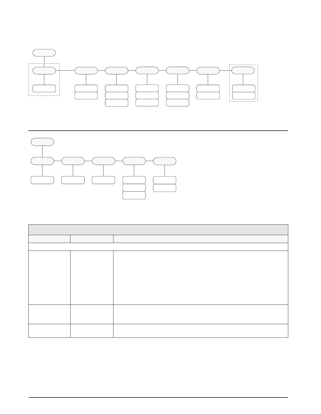
B
PAUSE, DELAY, and WAITSS Setpoints
VALUE
number
DELAY setpoints only
C
VALUE
0–255 1–8 1–8
TIMER and CONCUR Setpoints
PSHTARE
OFF
ON
START
PSHPRNT
OFF
ON
WAITSS
PSHACCM
OFF
ON
ONQUIET
ACCESS
OFF
ON
HIDE
DIGOUT
NONE
1–8
Figure 3-12. Submenu for PAUSE, DELAY, and WAITSS Setpoints
END
ACCESS
OFF
ON
HIDE
DIGOUT
NONE
1–8
Figure 3-13. Submenu for TIMER and CONCUR Setpoints
NAME
NONE
1–16
DELAY and WAITSS
setpoints only
SETPNTS Menu
Parameter Choices Description
Level 2 submenus
SETPT1–SETPT8 OFF
GROSSSP
NETSP
–RELSP
PAUSE
DELAY
WAITSS
TIMER
Specifies the setpoint kind.
GROSSSP, NETSP, and –RELSP setpoint kinds can be used as either batch or
continuous setpoints.
PAUSE, DELAY, and WAITSS setpoint kinds can only be used in batch sequences.
TIMER and CONCUR setpoint kinds can only be used as continuous setpoints.
See Table 8-1 on page 52 for more information about setpoint kinds.
CONCUR
BATCHNG OFF
AUTO
MANUAL
Batching enable. Set to AUTO or MANUAL to allow a batch sequence to run.
MANUAL requires a BATSTRT digital input or STRTBAT macro configuration before
the batch sequence can run. AUTO allows batch sequences to repeat continuously.
SPNAMES NAME1–NAME16 Allows specification of up to 16 setpoint names. Names can be assigned to
GROSSSP, NETSP, –RELSP, DELAY, and WAITSS setpoints.
Table 3-7. Setpoint Menu Parameters
28 IQ plus 710 Installation Manual
Page 32
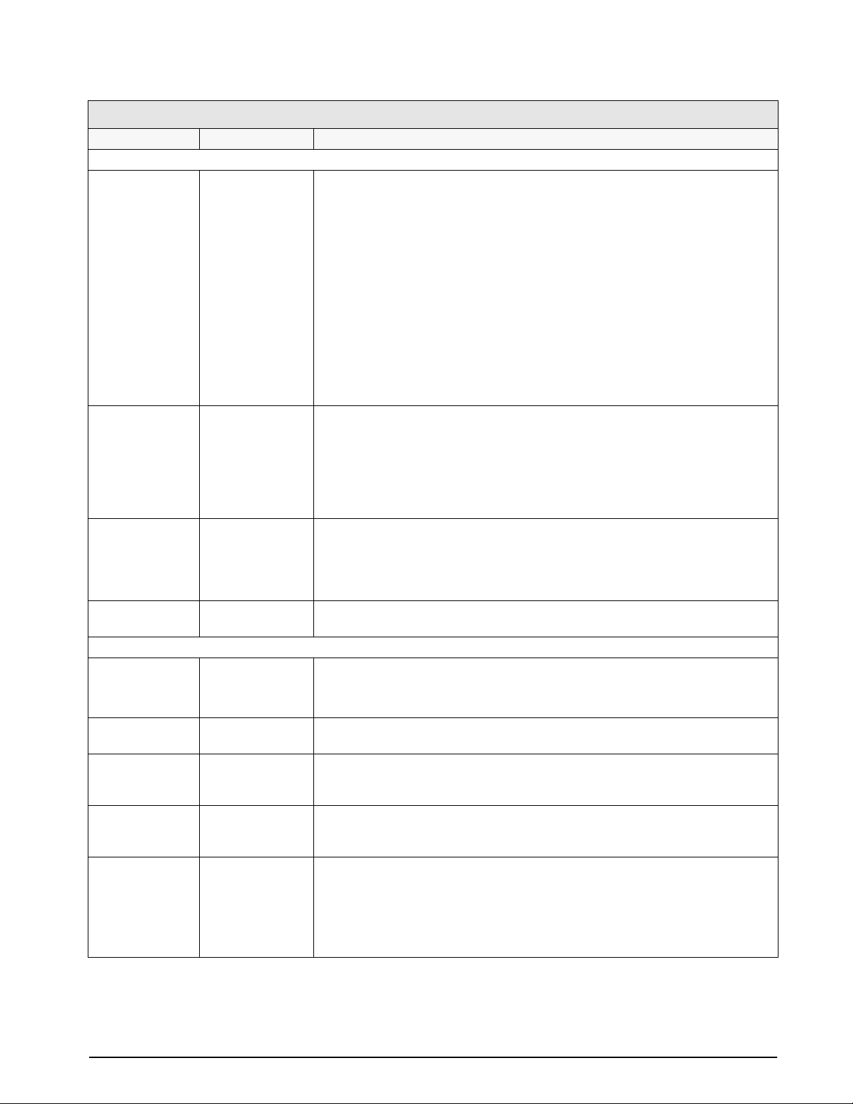
SETPNTS Menu
Parameter Choices Description
Level 3 submenus
GROSSSP
NETSP
–RELSP
PAUSE
DELAY
WAITSS
TIMER
CONCUR
NAME1–NAME16 name Specify up to 16 setpoint names. Names can be assigned to GROSSSP, NETSP,
Level 4 submenus
VALUE number GROSSSP, NETSP, –RELSP setpoint types: Specifies the target weight value.
VALUE
PSHTARE
PSHPRNT
TRIP
BANDVAL
HYSTER
ALARM
PSHACCM
PREACT
PREVAL
BATCH
ACCESS
NAME
DIGOUT
RELNUM
PSHTARE
PSHPRNT
PSHACCM
ACCESS
DIGOUT
NAME
VALUE
VALUE
START
END
ACCESS
DIGOUT
Configure GROSSSP, NETSP, and –RELSP setpoints. See Level 4 parameter
descriptions.
Configure PAUSE, DELAY, and WAITSS setpoints. See Level 4 parameter
descriptions.
Configure TIMER and CONCUR setpoints. See Level 4 parameter descriptions.
–RELSP, DELAY, and WAITSS setpoint types.
PSHTARE OFF
ON
PSHPRNT OFF
ON
WAITSS
PSHACCM OFF
ON
ONQUIET
TRIP HIGHER
LOWER
INBAND
OUTBAND
DELAY, TIMER, and CONCUR setpoint types: Specifies, in 0.1-second intervals, a
time value in the range 0–65535.
GROSSSP, NETSP, –RELSP, PAUSE, DELAY, and WAITSS setpoint types: Specify
ON to perform an acquire tare operation when the setpoint is satisfied.
GROSSSP, NETSP, –RELSP, PAUSE, DELAY, and WAITSS setpoint types: Specify
ON to perform a print operation when the setpoint is satisfied; specify WAITSS to
wait for standstill after setpoint is satisfied before printing.
GROSSSP, NETSP, –RELSP, PAUSE, DELAY, and WAITSS setpoint types: Specify
ON to update the accumulator and perform a print operation when the setpoint is
satisfied. Specify ONQUIET to update the accumulator without printing.
GROSSSP, NETSP, and –RELSP setpoint types: Specifies whether the setpoint is
tripped when the weight is higher or lower than the setpoint value, within a band
established around the value, or outside of that band.
In a batch sequence with TRIP=HIGHER, the associated digital output is active until
the setpoint value is reached or exceeded; with TRIP=LOWER, the output is active
until the weight goes below the setpoint value.
Table 3-7. Setpoint Menu Parameters
Configuration 29
Page 33
SETPNTS Menu
Parameter Choices Description
BANDVAL number GROSSSP, NETSP, and –RELSP setpoint types with TRIP=INBAND or OUTBAND:
Specifies a weight equal to half the band width. The band established around the
setpoint value is VALUE ±BANDVAL.
HYSTER number GROSSSP, NETSP, and –RELSP setpoint types: Specifies a band around the
setpoint value that must be exceeded before the setpoint, once off, can trip on again.
ALARM OFF
ON
PREACT OFF
ON
LEARN
PREVAL number GROSSSP, NETSP, and –RELSP setpoint types: Specifies the preact value for
BATCH OFF
ON
ACCESS OFF
ON
HIDE
NAME NONE, 1–16 GROSSSP, NETSP, –RELSP, DELAY, and WAITSS setpoint types: Specify the
DIGOUT NONE, 1–8 All setpoint types: Specifies a digital output associated with the setpoint. For
RELNUM 1–8 –RELSP setpoints: Specifies the number of the relative setpoint. The target weight
START 1–8 TIMER and CONCUR setpoint types: Specifies the starting setpoint number. Do not
END 1–8 TIMER and CONCUR setpoint types: Specifies the ending setpoint number. Do not
GROSSSP, NETSP, and –RELSP setpoint types: Specify ON to display the word
ALARM on the primary display while the setpoint is active (batch setpoints) or while
the setpoint is not tripped (continuous setpoints).
GROSSSP, NETSP, and –RELSP setpoint types: Allows the digital output associated
with a setpoint to shut off before the setpoint is satisfied to allow for material in
suspension.
The ON value adjusts the setpoint value up or down (depending on the TRIP
parameter value) from the setpoint value.
The LEARN value can be used to automatically adjust the preact value after each
batch. LEARN compares the actual weight at standstill to the target setpoint value,
then adjusts the preact by half of the difference after each batch.
setpoints with PREACT set to ON or LEARN. Depending on the TRIP value specified
for the setpoint, the setpoint trip value is adjusted up or down by the preact value.
GROSSSP, NETSP, and –RELSP setpoint types: Specifies whether the setpoint is
used as a batch (ON) or continuous (OFF) setpoint.
All setpoint types: Specifies whether the SETPOINT key can be used to change the
setpoint value in normal mode, including macro simulations of pressing the
SETPOINT key.
ON: Value can be displayed and changed
OFF: Value can be displayed but not changed
HIDE: Value cannot be displayed or changed
number of an assigned setpoint name.
continuous setpoints, the digital output is turned on when the condition is met; for
batch setpoints, the digital output is on until the setpoint condition is met.
for this setpoint is the setpoint value of the relative setpoint minus the setpoint value
of this setpoint.
specify the number of the TIMER or CONCUR setpoint itself. The TIMER or
CONCUR setpoint begins monitoring when the starting setpoint begins.
specify the number of the TIMER or CONCUR setpoint itself. The TIMER or
CONCUR setpoint stops monitoring when the ending setpoint begins.
30 IQ plus 710 Installation Manual
Table 3-7. Setpoint Menu Parameters
Page 34
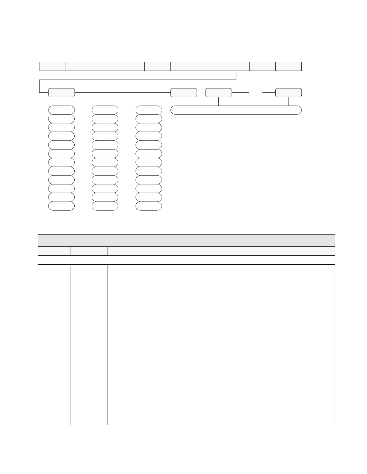
3.2.8 Digital Input Menu
DIGIN1
OFF
ZERO
NT/GRS
TARE
UNITS
PRINT
ACCUM
SETPNT
TIMDATE
ESC
ALPHAMD
CLEAR
FORMAT
DSPTAR
IDKEY
KF1
KF2
KF3
KF4
KEY1
KEY2
KEY3
KEY4
KEY5
KEY6
DIGIN2 DIGIN3 DIGIN8
KEY7
KEY8
KEY9
KEYDP
KEY0
ENTER
KBDLOC
HOLD
BATRUN
BATSTRT
BATPAUS
CLRCN
Figure 3-14. Digital Input Menu
XXXXXXX XXXXXXXXXXXXXX
Same as DIGIN1
ALGOUTDIG INSETPNTSPROGRM PFORMTSERIALCALIBRCONFIG
•••
VERS
DIG IN Menu
Parameter Choices Description
Level 2 submenus
DIGIN1
DIGIN2
DIGIN3
DIGIN4
DIGIN5
DIGIN6
DIGIN7
DIGIN8
OFF
ZERO
NT/GRS
TARE
UNITS
PRINT
ACCUM
SETPNT
TIMDATE
ESC
ALPHAMD
CLEAR
DSPTAR
IDKEY
KF1—KF4
KEY0—KEY9
KEYDP
ENTER
BATRUN
BATSTRT
BATPAUS
KBDLOC
HOLD
CLRCN
Specifies the function activated by digital inputs 1–8.
• ZERO, NT/GRS (net/gross mode toggle), TARE, UNITS, and PRINT provide the same
functions as the five major front panel keys.
• ACCUM, SETPNT, TIMDATE, ESC, ALPHAMD, CLEAR, DSPTAR, and IDKEY provide the
same functions as the front panel keys.
• KF1—KF4 are equivalent to pressing the macro keys, F1—F4.
• KEY0—KEY9 and KEYDP (decimal point) are simulate pressing keys on the numeric
keypad.
• ENTER simulates pressing the front panel ENTER key.
• BATRUN allows a batch routine to be started and run. With BA TRUN on (low), the BATSTRT
input starts the batch; if BATRUN is off (high), BATSTRT cancels the batch.
• BATSTRT starts or ends a batch routine, depending on the state of the BATRUN input.
• BATPAUS pauses a batch routine.
• KBDLOC locks the keyboard (indicator front panel).
• HOLD holds the current display. Releasing this input clears the running average filter.
• CLRCN resets the consecutive number to the value specified on the CONSTUP parameter
(PROGRM menu).
Table 3-8. Digital Input Menu Parameters
Configuration 31
Page 35
3.2.9 Analog Output Menu
The ALGOUT menu is used only if the analog output option is installed. If the analog output option is installed,
configure all other indicator functions and calibrate the indicator before configuring the analog output. See
Section 10.7 on page 69 for analog output calibration procedures.
SOURCE
GROSS
NET
OFFSET ERRACT
0%
20%
FULLSC
HOLD
ZEROSC
MIN
000000
number
XXXXXXX XXXXXXXALGOUTDIG INSETPNTSXXXXXXXPROGRM PFORMTSERIALCALIBRXXXXXXXCONFIG FORMAT
MAX TWZERO
10000
number
XXXXXXXVERS
TWSPAN
Figure 3-15. Analog Output Menu
ALG OUT Menu
Parameter Choices Description
Level 2 submenus
SOURCE1 GROSS
NET
OFFSET 0%
20%
ERRACT FULLSC
HOLD
ZEROSC
MIN 000000
number
MAX 010000
number
TWZERO — Tweak zero. Adjust the analog output zero calibration. Use a multimeter to monitor the analog
TWSPAN — Tweak span. Adjust the analog output span calibration. Use a multimeter to monitor the analog
Specifies the source tracked by the analog output.
Zero offset. Selects whether the analog output supplies voltage (0–10 V) or current (4–20 mA)
output. Select 0% for 0–10 V output; select 20% for 4–20 mA output.
Error action. Specifies how the analog output responds to system error conditions.
Possible values are:
FULLSC: Set to full value (10 V or 20 mA)
HOLD: Hold current value
ZEROSC: Set to zero value (0 V or 4 mA)
Specifies the minimum weight value tracked by the analog output. Specify a value in the range
0–9999800.
Specifies the maximum weight value tracked by the analog output. Specify a value in the range
0–9999800
output value. Press and hold or to adjust the output.
output value. Press and hold or to adjust the output.
Table 3-9. Analog Output Menu Parameters
3.2.10 Version Menu
The VERS menu is used to check the software version installed in the indicator. There are no parameters
associated with the Version menu: when selected, the indicator displays the installed software version number.
VERSALGOUTDIG INPROGRM PFORMTSERIALCALIBRCONFIG FORMAT
Software
version
32 IQ plus 710 Installation Manual
Figure 3-16. Version Menu
SETPNTS
XXXXXXXXXXXXXXXXXXXXX
Page 36
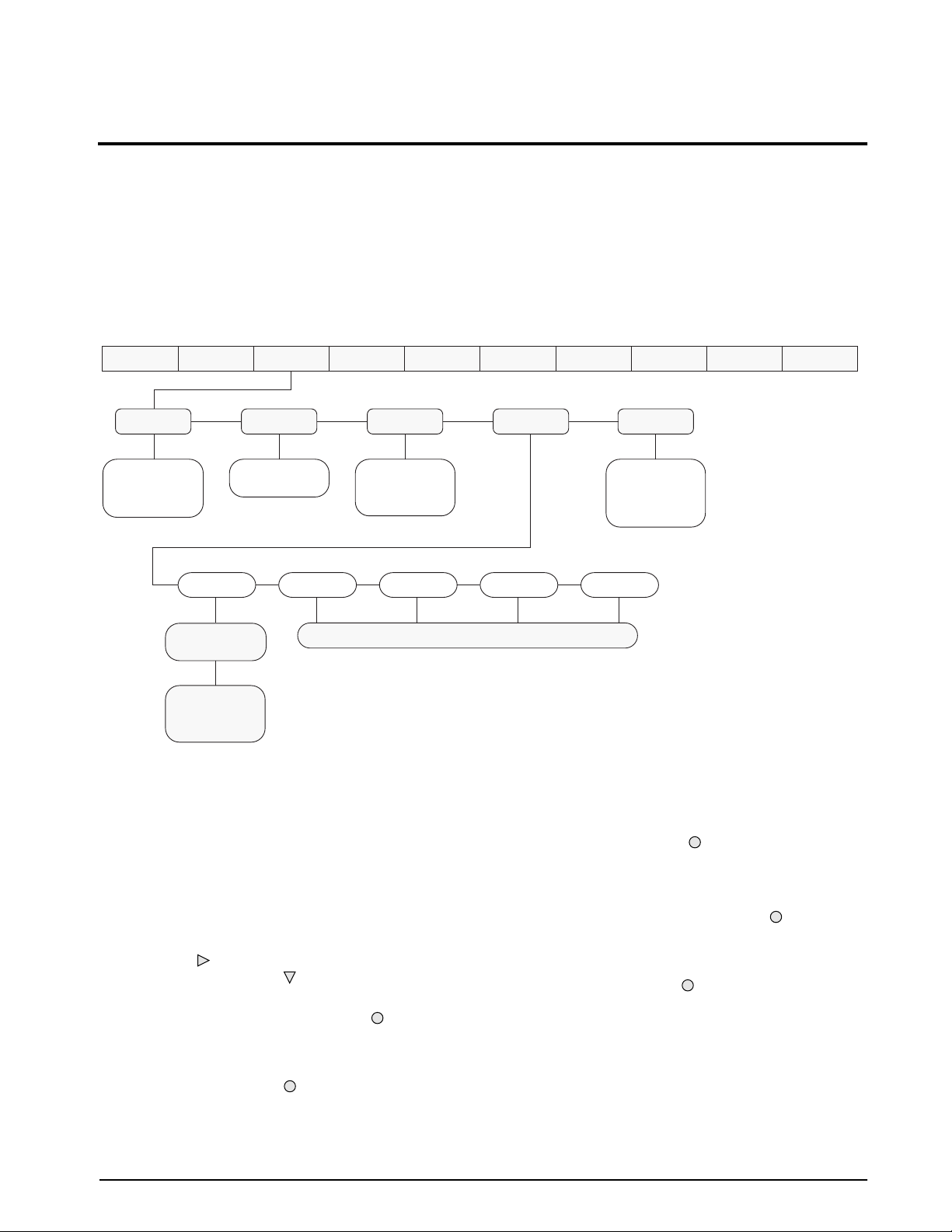
4.0 Calibration
The IQ plus 710 can be calibrated using the front panel, EDP commands, or the Revolution™ configuration
utility. Each method consists of the following steps:
• Zero calibration
• Entering the test weight value
• Span calibration
• Optional five-point linearization
• Optional rezero calibration for test weights using hooks or chains.
The following sections describe the calibration procedure for each of the calibration methods.
WZERO
*CALIB*
Display and edit
zero calibration
A/D count value
Display and edit
test weight value
Display and edit
linearization point
A/D count value
PT–> 1
*CALIB*
WVAL
Display and edit
test weight value
PT–> 2 PT–> 3 PT–> 4 PT–> 5
WSPAN
*CALIB*
Display and edit
span calibration
A/D count value
Same as PT-> 1
Figure 4-1. Calibration (CALIBR) Menu
4.1 Front Panel Calibration
To calibrate the indicator using the front panel, do the
following:
1. Place the indicator in setup mode (display
CONFIG) and remove all weight from
reads
the scale platform. If your test weights require
hooks or chains, place the hooks or chains on
the scale for zero calibration.
2. Press until the display reads
Figure 4-1). Press to go to zero calibration
(WZERO).
3. With
WZERO displayed, press to calibrate
zero. The indicator displays *CAL* while
calibration is in progress. When complete, the
A/D count for the zero calibration is
displayed. Press again to save the zero
calibration value and go to the next prompt
(WVAL).
CALIBR (see
4. With
XXXXXXX XXXXXXXXXXXXXXXXXXXXX
REZEROWLIN
*CALIB*
Press Enter to
remove offset from
zero and span
calibrations
ALGOUTDIGINSETPNTSPROGRM PFORMTSERIALCALIBRCONFIG FORMAT
WVAL displayed, place test weights on
VERS
the scale and press to show the test weight
value. Use the numeric keypad to enter the
actual test weight, then press ENTER to save
the value and go to span calibration (WSPAN).
5. With
WSP AN displayed, press to calibrate
span. The indicator displays *CAL* while
calibration is in progress. When complete, the
A/D count for the span calibration is
displayed. Press again to save the span
calibration value and go to the next prompt
(WLIN).
6. Five-point linearization (using the WLIN
parameter) provides increased scale accuracy
by calibrating the indicator at up to five
additional points between the zero and span
calibrations.
Calibration 33
Page 37

Linearization is optional: if you choose not to
perform linearization, skip the WLIN
parameter; if linearization values have
previously been entered, use the numeric
keypad to set each point to zero and press
ENTER. To perform linearization, follow the
procedure below:
WLIN displayed, Press to go to the
With
first linearization point (PT-> 1). Place test
weights on the scale and press or ENTER.
Use the numeric keypad to enter the actual
test weight value, then press ENTER to
calibrate. The indicator displays *CAL* while
calibration is in progress. When complete, the
A/D count for the linear calibration is
displayed. Press ENTER again to save the
calibration value and go to the next prompt
(PT-> 2).
Repeat for up to five linearization points. To
exit the linearization parameters, press to
return to WLIN.
4.2 EDP Command Calibration
To calibrate the indicator using EDP commands, the
indicator EDP port must be connected to a terminal or
personal computer. See Section 2.3.2 on page 6 for
EDP port pin assignments; see Section 5.0 on page 37
for more information about using EDP commands.
Once the indicator is connected to the sending device,
do the following:
1. Place the indicator in setup mode (display
CONFIG) and remove all weight from
reads
the scale platform. If your test weights require
hooks or chains, place the hooks or chains on
the scale for zero calibration.
2. Send the WZERO EDP command to calibrate
zero. The indicator displays
calibration is in progress.
3. Place test weights on the scale and use the
WVAL command to enter the test weight
value in the following format:
WVAL=nnnnnn<CR>
4. Send the WSPAN EDP command to calibrate
span. The indicator displays *CAL* while
calibration is in progress.
*CAL* while
7. The optional rezero function is used to
remove a calibration offset when hooks or
chains are used to hang the test weights.
• If no other apparatus was used to hang the
test weights during calibration, remove
the test weights and press to return to
the CALIBR menu.
• If hooks or chains were used during
calibration, remove these and the test
weights from the scale. With all weight
removed, press
ENTER to rezero the
scale. This function adjusts the zero and
span calibration values. The indicator
displays *CAL* while the zero and span
calibrations are adjusted. When complete,
the adjusted A/D count for the zero
calibration is displayed. Press ENTER to
save the value, then press to return to
the CALIBR menu.
8. Press until the display reads
CONFIG, then
press to exit setup mode.
5. Up to five linearization points can be
calibrated between the zero and span
calibration values. Use the following
commands to set and calibrate a single
linearization point:
WLIN.V1=nnnnn<CR>
WLIN.C1<CR>
The WLIN.V1 command sets the test weight
value (nnnnn) for linearization point 1. The
WLIN.C1 command calibrates the point.
Repeat using the WLIN.Vx and WLIN.Cx
commands as required for additional
linearization points.
6. To remove an offset value, clear all weight
from the scale, including hooks or chains used
to hang test weights, then send the REZERO
EDP command. The indicator displays
*CAL*
while the zero and span calibrations are
adjusted.
7. Send the KUPARROW or KEXIT EDP
command to exit setup mode.
34 IQ plus 710 Installation Manual
Page 38
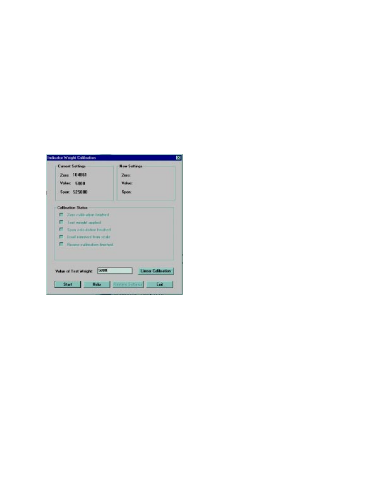
4.3 Revolution™ Calibration
To calibrate the indicator using Revolution, the
indicator EDP port must be connected to a PC running
the Revolution configuration utility.
Use the following procedure to calibrate the indicator:
1. Select
main menu.
2. On the Indicator Calibration display, select
the indicator model (
communications port then click OK.
3. Revolution uploads calibration data from the
indicator then presents the information in a
display like that shown in Figure 4-2.
Calibrate Indicator from the Revolution
IQ+710) and
4. Enter the Value of Test Weight to be used for
span calibration then click OK.
5. The Zero Calibration dialog box prompts you
to remove all weight from the scale. Clear the
scale and click
NOTE: If your test weights require hooks or
OK to begin zero calibration.
chains, place the hooks or chains on the scale
for zero calibration.
6. When zero calibration is complete, the Span
Calibration dialog box prompts you to place
test weights on the scale for span calibration.
Place tests weights on the scale then click
OK.
7. When span calibration is complete, the
Rezero dialog box prompts you to remove
weights from the scale. Remove the weights
then click
8. When calibration is complete, the
Settings fields of the Indicator Calibration
OK.
New
display are filled in. Click Exit to save the new
values and return to the Revolution main
menu; to restore the previous calibration
values, click Restore Settings.
Figure 4-2. Revolution Calibration Display
Calibration 35
Page 39

4.4 More About Calibration
The following topics provide additional information
that may be useful when calibrating the indicator with
no attached scale (Section 4.4.1) or when calibrating a
heavy capacity scale without test weights
(Section 4.4.2).
4.4.1 Zero Deadload A/D Counts
Table 4-1 lists the ideal A/D counts that result from
input signals of 0–45 mV with zero deadload. Actual
values will typically be higher than the values shown
in Table 4-1 but the ideal values can be used when
calibrating the indicator with no attached scale.
Input Signal (mV) Raw A/D Count
0 105 000
1 126 000
2 147 000
3 168 000
4 189 000
5 210 000
6 231 000
7 252 000
8 273 000
9 294 000
10 315 000
15 420 000
20 525 000
30 735 000
45 1 050 000
Table 4-1. Ideal A/D Raw Counts
4.4.2 Calculating the Span Coefficient
In applications where absolute accuracy is not
required, or where the use of test weights is not
practical and not required, the IQ plus 710 can be
calibrated using a calculated span coefficient. The
span coefficient is determined using the following
formula:
Span_coefficient =
((21000) * mV_signal _input) + zero_coefficient
To use the formula, you will need to determine the full
scale input signal value (based on the rated full scale
signal output of the load cells) and perform a zero
calibration. These procedures are described in the
following sections.
Calculate Full Scale Signal Input Value
In the span coefficient equation, mV_signal_input is the
full scale signal input (in mV) of the load cells. For a
single load cell scale, multiply the rated signal output
of the load cell (listed on the manufacturer’s cert or
load cell label) by the excitation voltage (10 V). For
scales with multiple load cells, record the rated signal
output of each cell, then multiply the average of these
values by the excitation voltage (10 V).
NOTE: If the scale will be calibrated for a full scale value
less than the capacity of the load cells, multiply the full
scale signal input value by the ratio of calibrated
capacity over the sum of the load cell capacities.
For example, to determine the full scale signal input
value for a scale platform with the following:
• Four 10,000-lb load cells with full scale signal
outputs rated at 3.0116, 3.0043, 2.9978, and 3.1863
mV/V
• Full scale capacity to be calibrated at 30,000 lb
The averaged full scale output of the load cells is 3.05
mV/V (sum of the four values, divided by four). The
sum of the load cell capacities is 40,000 lb, but
because the scale will be calibrated to a full scale
value of 30,000 lb, the full scale signal will be reached
at 2.2875 mV/V:
(30000 / 40000) * 3.05 mV/V = 2.2875 mV/V
Multiplying this value by the excitation voltage (10 V)
gives the full scale signal input value:
2.2875 mV/V * 10 V = 22.875 mV
Perform Calibration
To complete the span coefficient calculation, begin
calibrating the indicator as described in Section 4.1 on
page 33.
zero_coefficient value in the span coefficient
The
equation is the A/D count displayed after performing
the WZERO calibration step. Record this value, then
use the equation to calculate the span coefficient.
Using the full scale signal input value determined in
the example above and assuming that the value
displayed after performing zero calibration was
140385, the span coefficient is calculated as follows:
Span_coefficient = (21000 * 22.875 mV) + 140385
= 480375 + 140385
= 620760
The span coefficient value entered will be 620760.
Continue calibration. Enter the full scale weight value
on the WVAL parameter (30000 in this example) then
perform span calibration (WSPAN parameter). With
no test weights applied to the scale, the A/D count
displayed after performing the WSPAN calibration
will be the same as the zero calibration value. Use the
front panel keys to change the displayed value to the
calculated value (620760). Save the value, then exit
calibration.
36 IQ plus 710 Installation Manual
Page 40
5.0 EDP Commands
The IQ plus 710 indicator can be controlled by a
personal computer or remote keyboard connected to
the indicator EDP port. Control is provided by a set of
EDP commands that can simulate front panel key
press functions, display and change setup parameters,
and perform reporting functions. The EDP port
provides the capability to print configuration data or to
save that data to an attached personal computer. This
section describes the EDP command set and
procedures for saving and transferring data using the
EDP port.
5.1 The EDP Command Set
The EDP command set can be divided into five
groups: key press commands, reporting commands,
the RESETCONFIGURATION special function
command, parameter setting commands, and transmit
weight data commands.
When the indicator processes an EDP command, it
responds with the message
verifies that the command was received and has been
executed. If the command is unrecognized or cannot
be executed, the indicator responds with
The following sections list the commands and
command syntax used for each of these groups.
5.1.1 Key Press Commands
Key press EDP commands (see Table 5-1) simulate
pressing the keys on the front panel of the indicator.
These commands can be used in both setup and
weighing mode. Several of the commands serve as
“pseudo” keys, providing functions that are not
represented by a key on the front panel.
For example, to enter a 15-pound tare weight using
EDP commands:
1. Type K1 and press
2. Type K5 and press
3. Type KTARE and press
Command Function
KZERO Press the ZERO key
KGROSSNET Press the GROSS/NET key
KGROSS Go to gross mode (pseudo key)
KNET Go to net mode (pseudo key)
KTARE Press the TARE key
KUNITS Press the UNITS key
KPRIM Go to primary units (pseudo key)
OK. The OK response
??.
ENTER (or RETURN).
ENTER.
ENTER.
Command Function
KSEC Go to secondary units (pseudo key)
KPRINT Press the PRINT key
KNEWID Press the ID key
KSETPOINT Press the SETPOINT key
KTIMEDATE Press the TIME/DATE key
KTIME Display time (pseudo key)
KDATE Display date (pseudo key)
KESCAPE Press the ESCAPE key
KALPHA Press the ALPHA ENTRY key
KDISPACCUM Press the ACCUM key
KDISPTARE Press the DISPLAY TARE key
KCLR Press the CLEAR key
KCLRCN Reset consecutive number (pseudo key)
KLEFTARROW In setup mode, move left in the menu;
in weighing mode, press the UNITS key
KRIGHTARROW In setup mode, move right in the menu;
in weighing mode, press the PRINT key
KUPARROW In setup mode, move up in the menu;
in weighing mode, press the ZERO key
KDOWNARROW In setup mode, move down in the
menu; in weighing mode, press the
GROSS/NET key
KEXIT In setup mode, exits to normal mode
K0 Press number 0 (zero)
K1 Press number 1
K2 Press number 2
K3 Press number 3
K4 Press number 4
K5 Press number 5
K6 Press number 6
K7 Press number 7
K8 Press number 8
K9 Press number 9
KDOT Press the decimal point (.)
KENTER Press the ENTER key
KF1 Play MACRO1
KF2 Play MACRO2
KF3 Play MACRO3
KF4 Play MACRO4
Table 5-1. EDP Key Press Commands (Continued)
Table 5-1. EDP Key Press Commands
EDP Commands 37
Page 41
5.1.2 Reporting Commands
Reporting commands (see Table 5-2) send specific
information to the EDP port. These commands can be
used in both setup mode and normal mode.
Command Function
DUMPALL List all parameter values
VERSION
P Write current displayed weight with units
S Write one frame of stream format
5.1.4 Parameter Setting Commands
Write IQ plus 710 software version
identifier. See Section 10.2 on page 63 for
more information.
Table 5-2. EDP Reporting Commands
Parameter setting commands allow you to display or
change the current value for a particular configuration
parameter (Tables 5-3 through 5-12).
Current configuration parameter settings can be
displayed in either setup mode or normal mode using
the following syntax:
command<ENTER>
Most parameter values can be changed in setup mode
only; setpoint parameters listed in Table 5-8 on
page 41 can be changed when in normal weighing
mode.
5.1.3 The RESETCONFIGURATION Command
The RESETCONFIGURATION command can be
used to restore all configuration parameters to their
default values. Before issuing this command, the
indicator must be placed in test mode (press and hold
setup switch for approximately three seconds).
This command is equivalent to using the DEFAULT
function in TEST mode. See Section 10.8 on page 69
for more information about test mode.
NOTE: All load
cell calibration settings are lost when the
RESETCONFIGURATION command is run.
Use the following command syntax when changing
parameter values:
command=value<ENTER>
where value is either a number or a parameter value.
Use no spaces before or after the equal (=) sign. If you
type an incorrect command, the display reads
??.
For example, to set the motion band parameter to 5,
type the following:
MOTBAND=5D<ENTER>
Command Description Values
GRADS Graduations 1–100000
ZTRKBND Zero track band OFF, 0.5D, 1D, 3D
ZRANGE Zero range 1.9%, 100%
MOTBAND Motion band 1D, 2D, 3D, 5D, 10D, 20D, OFF
OVRLOAD Overload FS+2%, FS+1D, FS+9D, FS
DIGFLTR Digital filtering 1, 2, 4, 8, 16, 32, 64, 128, 256, 1RT, 2RT, 4RT, 8RT, 16RT, 32RT,
64RT, 128RT, 256RT
DFSENS Digital filter cutout sensitivity 2OUT, 4OUT, 8OT, 16OUT, 32OUT, 64OUT, 128OUT
DFTHRH Digital filter cutout threshold NONE, 2DD, 5DD, 10DD, 20DD, 50DD, 100DD, 200DD, 250DD
PWRUPMD Power up mode GO, DELAY
TAREFN Tare function BOTH, NOTARE, PBTARE, KEYED
Table 5-3. CONFIG EDP Commands
Command Description Values
PRI.DECPNT Primary units decimal position 8.888888, 88.88888, 888.8888, 8888.888, 88888.88, 888888.8,
8888888, 8888880, 8888800
PRI.DSPDIV Primary units display divisions 1D, 2D, 5D
PRI.UNITS Primary units LB, KG, G, OZ, TN, T, GN, TROYOZ, TROYLB, LT, NONE
38 IQ plus 710 Installation Manual
Table 5-4. FORMAT EDP Commands
Page 42
Command Description Values
SEC.DECPNT Secondary units decimal
position
SEC.DSPDIV Secondary units display divisions 1D, 2D, 5D
SEC.UNITS Secondary units LB, KG, G, OZ, TN, T, GN, TROYOZ, TROYLB, LT, NONE
SEC.MULT Secondary units multiplier 0.00000–99999.99
DECFMT Decimal format DOT, COMMA
DSPRATE Display rate 250MS, 500MS, 750MS, 1500MS, 2SEC, 2500MS, 3SEC, 4SEC,
8.888888, 88.88888, 888.8888, 8888.888, 88888.88, 888888.8,
8888888, 8888880, 8888800
6SEC, 8SEC
Table 5-4. FORMAT EDP Commands (Continued)
Command Description Values
WZERO Zero calibration —
WVAL Test weight value test_weight_value
WSPAN Span calibration —
WLIN.F1–WLIN.F5 Actual raw count value for linearization points 1–5 —
WLIN.V1–WLIN.V5 Test weight value for linearization points 1–5 test_weight_value
WLIN.C1–WLIN.C5 Calibrate linearization points 1–5 —
REZERO Rezero —
LC.CD Set deadload coefficient value
LC.CW Set span coefficient value
Table 5-5. CALIBR EDP Commands
Command Description Values
EDP.BAUD EDP port baud rate 300, 600, 1200, 2400, 4800, 9600, 19200
EDP.BITS EDP port data bits/parity 8NONE, 7EVEN, 7ODD
EDP.TERMIN EDP port termination character CR/LF, CR
EDP.EOLDLY EDP port end-of-line delay 0–255 (0.1-second intervals)
EDP.HANDSHK EDP port handshaking OFF, ON
EDP.ADDRESS EDP port RS-485 address 0, 01–255
EDP.AB-RIO EDP port Remote I/O stream OFF, ON
EDP.STREAM EDP port streaming OFF, ON
PRN.BAUD Printer port baud rate 300, 600, 1200, 2400, 4800, 9600, 19200
PRN.BITS Printer port data bits/parity 8NONE, 7EVEN, 7ODD
PRN.TERMIN Printer port termination character CR/LF, CR
PRN.EOLDLY Printer port end-of-line delay 0–255 (0.1-second intervals)
PRN.HANDSHK Printer port handshaking OFF, ON
PRN.STREAM Printer port streaming OFF, ON
PRNDEST Print destination EDP, PRN, BOTH
Table 5-6. SERIAL EDP Commands
EDP Commands 39
Page 43
Command Description Values
SD Set date MMDDYY or DDMMYY (enter using DATEFMT specified)
ST Set time hhmm (enter using 24-hour format)
DATEFMT Date format MMDDYY, DDMMYY
DATESEP Date separator SLASH, DASH, SEMI
TIMEFMT Time format 12HOUR, 24HOUR
TIMESEP Time separator COLON, COMMA
CONSTUP Consecutive number start-up value 0–999 999
TARE100 Truck in/out mode OFF, MODE1, MODE2, MODE3, MODE4, MODE5, MODE6
ACCUM Accumulator OFF, ON
CFGPWD Configuration password 0, 1–9999999
SPPWD Setpoint password 0, 1–9999999
KYBDLK Keyboard lock (disable keypad) OFF, ON
LOCKON Lock indicator front panel in
operating mode
LOCKOFF Unlock indicator front panel in
operating mode
AUXLK Disable auxiliary keyboard OFF, ON
MACONLY Disable all except macro keys OFF, ON
ZERONLY Disable all keys except ZERO OFF, ON
ALPHAKB Enable ALPHA ENTRY key OFF, ON
REGULAT Regulatory compliance NONE, OIML, NTEP, CANADA
PROMPT#1–
PROMPT#60
MACRO1.K01–
MACRO1.K30
MACRO2.K01–
MACRO2.K30
MACRO3.K01–
MACRO3.K30
MACRO4.K01–
MACRO4.K30
Macro prompt See Section 9.0 on page 55 for information about macro
Set MACRO1 keystroke
Set MACRO2 keystroke
Set MACRO3 keystroke
Set MACRO4 keystroke
Same function as KYBDLK command
programming
40 IQ plus 710 Installation Manual
Table 5-7. PROGRM EDP Commands
Page 44
Command Description Values
SETPOINT Setpoint number 1–8
KIND Setpoint kind OFF, GROSSSP , NETSP, –RELSP, PAUSE, DELAY, WAITSS, TIMER,
CONCUR
VALUE Setpoint value number
PSHTARE Push tare OFF, ON
PSHPRINT Push print OFF, ON, WAITSS
PSHACCM Push accumulate OFF, ON, ONQUIET
TRIP Trip HIGHER, LOWER, INBAND, OUTBAND
BANDVAL Band value number
HYSTER Hysteresis number
ALARM Alarm OFF, ON
PREACT Preact OFF, ON, LEARN
PREVAL Preact value number
BATCH Batch step enable OFF, ON
NAME Setpoint name number NONE, 1–16
ACCESS Setpoint access OFF, ON, HIDE
DIGOUT Digital output NONE, 1–8
RELNUM Relative setpoint numer 1–8
START Starting setpoint 1–8
END Ending setpoint 1–8
BATCHNG Batching mode OFF, AUTO, MANUAL
SPNAME#1—
SPNAME#16
Setpoint names name
Table 5-8. SETPNTS EDP Commands
Command Description Values
GFMT Gross demand print format string See Section 6.0 on page 45 for detailed information
NFMT Net demand print format string
SPFMT Setpoint print format string
TRWIN Truck weigh-in print format string
TRWOUT Truck weigh-out print format string
EDPFMT EDP demand print format string
HDRFMT Ticket header format string
Table 5-9. PFORMT EDP Commands
Command Description
DON#nn Set digital output nn on
DOFF#nn Set digital output nn off
DOFF#0 Set all digital outputs off
For commands ending with “#nn”, nn is the digital output (01–8) being set on or off.
Table 5-10. DIG OUT EDP Commands
EDP Commands 41
Page 45
Command Description Values
DIGIN1
DIGIN2
DIGIN3
DIGIN4
DIGIN5
DIGIN6
DIGIN7
DIGIN8
Digital input function OFF, ZERO, NT/GRS, TARE, UNITS, PRINT, ACCUM, SETPNT,
TIMDATE, ESC, ALPHAMD, CLEAR, DSPTAR, IDKEY, KF1–KF4,
KEY0–KEY9, KEYDP, ENTER, BATRUN, BATSTRT, BATPAUS,
KBDLOC, HOLD, CLRCN
Table 5-11. DIG IN EDP Commands
Command Description Values
SOURCE1 Analog output source GROSS, NET
OFFSET Zero offset 0%, 20%
ERRACT Error action FULLSC, HOLD, ZEROSC
MIN Minimum value tracked 0–9 999 800
MAX Maximum value tracked 0–9 999 800
ZERO1 Zero calibration 0–16 383
SPAN1 Span calibration 0–16 383
Table 5-12. ALGOUT EDP Commands
5.1.5 Normal Mode Commands
The normal mode commands (see Table 5-13) transmit data to the EDP port on demand. These commands are
valid only in normal operating mode.
Command Description Response Format
CONSNUM Set consecutive number 0–999 999
SD Set date MMDDYY or DDMMYY (enter using DATEFMT specified)
ST Set time hhmm (enter using 24-hour format)
SX Start EDP streaming OK or ??
EX Stop EDP streaming OK or ??
DX Start streaming raw A/D counts OK or ??
RS Reset system —
XA Transmit accumulator value nnnnnn UU
where nnnnnn is the weight value, UU is the units.XG Transmit gross weight in displayed units
XN Transmit net weight in displayed units
XT Transmit tare weight in displayed units
XG2 Transmit gross weight in non-displayed units
XN2 Transmit net weight in non-displayed units
XT2 Transmit tare weight in non-displayed units
XE Query system error conditions nnnnn nnnnn
See Section 10.1 on page 62 for detailed information about
the XE command response format.
Table 5-13. Normal Mode EDP Commands
42 IQ plus 710 Installation Manual
Page 46
5.1.6 Batching Control Commands
The commands listed below provide batching control through the EDP port.
BATSTART
If the BATRUN digital input is on or not assigned, the BATSTART command can be used to start the batch
program.
BATRESET
Stops the program and resets the batch program to the first batch step.
BATPAUSE
Stops the batch program at the current step. All digital outputs set on by the current step are set off. The
BATSTRT DIGIN, BATSTART EDP command, or a macro configured with STRTBAT=ON can be used to
restart the batch program at the current step.
BATSTATUS
The BATSTATUS command is used to check the current status of various setpoint and batching conditions.
BATSTATUS returns 14 bytes of status data as described in Table 5-14. BATSTATUS is principally used to
provide status information to a controlling batch program when using the Remote I/O Interface option.
Status information returned in bytes 3–12 is coded as ASCII characters @ (hex 40) through O (hex 4F);
only the low order bits of these characters are significant. Table 5-14 shows the low order bit assignments
for bytes 3–12. Use Table 5-15 on page 44 to interpret the status of the low order bits for a given ASCII
character.
Batch Status Data Byte Values
Batch Status
Current Batch Step
Continuous Setpoint Status
Low order bits of bytes 3–4 are set on
to indicate continuous setpoints for
which conditions are being met. Bits are
assigned to setpoint numbers as shown
at right.
Digital Output Status
Low order bits of bytes 8–9 are set on
to indicate active digital outputs. Bits
are assigned to digital outputs as
shown at right.
Digital Input / Alarm Status
Low order bits of byte 12 are set on to
indicate active digital inputs and
setpoint alarm status. Bits are assigned
as shown at right.
Carriage Return
0 “S” = stopped
“R” = running
“P” = paused
1 – 2 00 – 08
Low Order Bit Assignments for Bytes 3 – 12 ASCII Values
3 – 7
3 SP 1 SP 2 SP 3 SP 4
4 SP 5 SP 6 SP 7 SP 8
5 N/A
6
7
8 – 11
8 DIGOUT 1 DIGOUT 2 DIGOUT 3 DIGOUT 4
9 DIGOUT 5 DIGOUT 6 DIGOUT 7 DIGOUT 8
10 N/A
11
12 DIGIN 1 DIGIN 2 DIGIN 3 Alarm @ – O
13 N/A (CR)
Bit 3 Bit 2 Bit 1 Bit 0 @@@@@ – OOOOO
Bit 3 Bit 2 Bit 1 Bit 0 @@@@ – OOOO
Table 5-14. BATSTATUS Command Structure
EDP Commands 43
Page 47
Translating ASCII Status Data ASCII Value Bit 3 Bit 2 Bit 1 Bit 0
Use the table at right to evaluate the ASCII character
output for bytes 3 – 12 and determine which of the
low order bits are set on.
For example, if the Digital Output Status returned in
bytes 8 – 11 is AC@@, the table at right can be used
with the bit assignments described above to
determine that digital outputs 4, 7, and 8 are active:
• A (byte 8) indicates that DIGOUT 4 (bit 0) is on
• C (byte 9) indicates that DIGOUTs 7 and 8 (bits 1
and 0) are on
• @@ indicates that bytes 10 and 11 are not used
Table 5-15. ASCII Translation Table for BATSTATUS Data
@0000
A0001
B0010
C0011
D0100
E0101
F0110
G0111
H1000
I1001
J1010
K1011
L1100
M1101
N1110
O1111
5.2 Saving and Transferring Data
Connecting a personal computer to the IQ plus 710
EDP port allows you to save indicator configuration
data to the PC or to download configuration data from
the PC to an indicator. The follo wing sections describe
the procedures for these save and transfer operations.
5.2.1 Saving and Printing Indicator Data
Configuration data can be saved to a personal
computer connected to the EDP port. The PC must be
running a communications program such as
PROCOMMPLUS
information about serial communications wiring and
EDP port pin assignments.
When configuring the indicator, ensure that the values
set for the BAUD and BITS parameters on the
SERIAL menu match the baud rate, bits, and parity
settings configured for the serial port on the PC.
To save all configuration data, send the DUMPALL
EDP command to the indicator. The IQ plus 710
responds by sending all configuration parameters to
the PC as ASCII-formatted text.
Configuration data can also be sent to the printer port:
To print configuration data, place the indicator in
setup mode, then press the
®
. See Section 2.3.2 on page 6 for
ID key.
5.2.2 Downloading Configuration Data from PC to
Indicator
Configuration data saved on a PC or floppy disk can
be downloaded from the PC to an indicator. This
procedure is useful when a number of indicators with
similar configurations are set up or when an indicator
is replaced.
To download configuration data, connect the PC to the
EDP port as described in Section 5.2.1. Place the
indicator in setup mode and use the PC
communications software to send the saved
configuration data to the indicator. When transfer is
complete, calibrate the indicator as described in
Section 4.0 on page 33.
NOTES:
• Calibration settings are included in the configuration
data downloaded to the indicator. If the receiving
indicator is a direct replacement for another IQ plus
710 and the attached scale is not changed,
recalibration is not required.
• When downloading configurations that include
changed serial communications settings, edit the data
file to place the serial communications changes at the
end of the file. Communication between the PC and
indicator will be lost once the indicator receives
settings for baud rate (BAUD parameter) or data bits
and parity (BITS parameter) that do not match those
configured for the PC.
44 IQ plus 710 Installation Manual
Page 48
6.0 Print Formatting
The IQ plus 710 provides six print formats that determine the format of the printed output when the PRINT key is
pressed or when a KPRINT EDP command is received. Supported print formats are: GFMT, NFMT, EDPFMT,
TRWIN, TRWOUT, and SPFMT. A fourth format, HDRFMT, allows specification of up to 300 characters of
ticket header information for use on GFMT, NFMT, and EDPFMT tickets. The contents of the HDRFMT format
can be inserted into any other ticket format using the <AE> formatting command.
The particular ticket format used for a given print operation depends on the indicator configuration (see Table 6-2
on page 46).
Each print format can be customized to include up to 300 characters of information, such as company name and
address, on printed tickets. You can use the indicator front panel (PFORMT menu), EDP commands, or the
Revolution
6.1 Print Formatting Commands
Table 6-1 lists commands you can use to format the IQ plus 710 print formats. Commands included in the format
strings must be enclosed between < and > delimiters. Any characters outside of the delimiters are printed as text
on the ticket. Text characters can include any ASCII character that can be printed by the output device.
Command Description
<G> Gross weight in displayed units √√
<G2> Gross weight in non-displayed units √√
<N> Net weight in displayed units √√
<N2> Net weight in non-displayed units √√
<T> Tare weight in displayed units √√
<T2> Tare weight in non-displayed units √√
<A> Accumulated weight in displayed units √
<AC> Number of accumulator event (5-digit counter) √
<AT> Time of last accumulator event √
<AD> Date of last accumulator event √
<TR1> Gross weight for current ticket in displayed units √
<TR2> Tare weight for current ticket in displayed units √
<TR3> Net weight for current ticket in displayed units √
<SV1> Setpoint value when tripped in displayed units √
<SV2> Label for SV1 value √
<BN> Current setpoint number √
<NA> Current setpoint name √
<TI> Time √√√
<DA> Date √√√
<TD> Time and date √√√
<ID> ID number √√√
<CN> Consecutive number √√√
<AE> Ticket header (HDRFMT) √√√
™
configuration utility to customize the print formats.
GFMT/NFMT/
EDPFMT
Ticket Format
TRWIN/TRWOUT SPFMT
Table 6-1. Print Format Commands
Print Formatting 45
Page 49
Ticket Format
GFMT/NFMT/
Command Description
<NLnn> New line (nn = number of termination (<CR/LF> or
<CR>) characters)*
<SPnn> Space (nn = number of spaces)* √√√
<SU> Toggle weight data format (formatted/unformatted)** √√√
NOTES:
Gross, net, and tare weights, SV1 setpoint weight are 9 digits in length, including sign (10 digits with decimal point), followed by
a space and a two-digit units identifier. Total field length with units identifier is 12 (or 13) characters.
TR1, TR2, and TR3 truck ticket weight data includes keywords INBOUND, KEYED, RECALLED, as necessary.
ID and consecutive number (CN) fields are 1–7 characters in length, as required.
Ticket header (AE) inserts information specified for the HDRFMT header format.
* If nn is not specified, 1 is assumed. Value must be in the range 1–99.
** After receiving an SU command, the indicator sends unformatted data until the next SU command is received. Unformatted
data omits decimal points, leading and trailing characters.
EDPFMT
√√√
TRWIN/TRWOUT SPFMT
Table 6-1. Print Format Commands (Continued)
NOTE: The <G2>, <N2>, and <T2> commands listed in Table 6-1 print the gross, net, and tare weights in
non-displayed units—that is, in the units not currently displayed on the indicator.
6.2 Default Ticket Formats
Table 6-2 shows the default print formats for the IQ plus 710 and lists the conditions under which each print
format is used. The HDRFMT format is used to specify header information that can be used by the other ticket
formats. The contents of the HDRFMT format can be inserted into any other ticket format using the <AE>
formatting command.
Format Default Format String Used When
GFMT GROSS<G><NL2><TD><NL> Normal mode, no tare in system
NFMT GROSS<G><NL>TARE<SP><T><NL>NET<SP2><N>
<NL2><ID><NL>
EDPFMT GROSS<G><NL2><TD><NL> Normal mode, PRNDEST=BOTH (SERIAL
TRWIN <NL>ID<SP><ID><NL2>GROSS<TR1>
<NL2><DA><SP><TI><NL>
TRWOUT <NL6>ID<SP><ID><NL2>GROSS<TR1><NL>TARE<SP><TR2>
<NL>NET<SP2><TR3><NL2><DA><SP><TI><NL>
SPFMT <SV1><SP><SV2><NL> Setpoint push print operation (PSHPRNT=ON)
HDRFMT COMPANY NAME<NL>STREET ADDRESS<NL>
CITY, ST ZIP<NL2>
NOTE: In OIML and CANADA modes, the letters PT (preset tare) are automatically inserted after the printed tare weight.
Table 6-2. Default Print Formats
Normal mode, tare in system
menu). GFMT (or NFMT) print format is sent to
printer port simultaneously.
Truck mode (T ARE100 ≠ OFF), when truck ID is
entered
Truck mode (TARE100 ≠ OFF), when PRINT
key pressed
N/A
46 IQ plus 710 Installation Manual
Page 50
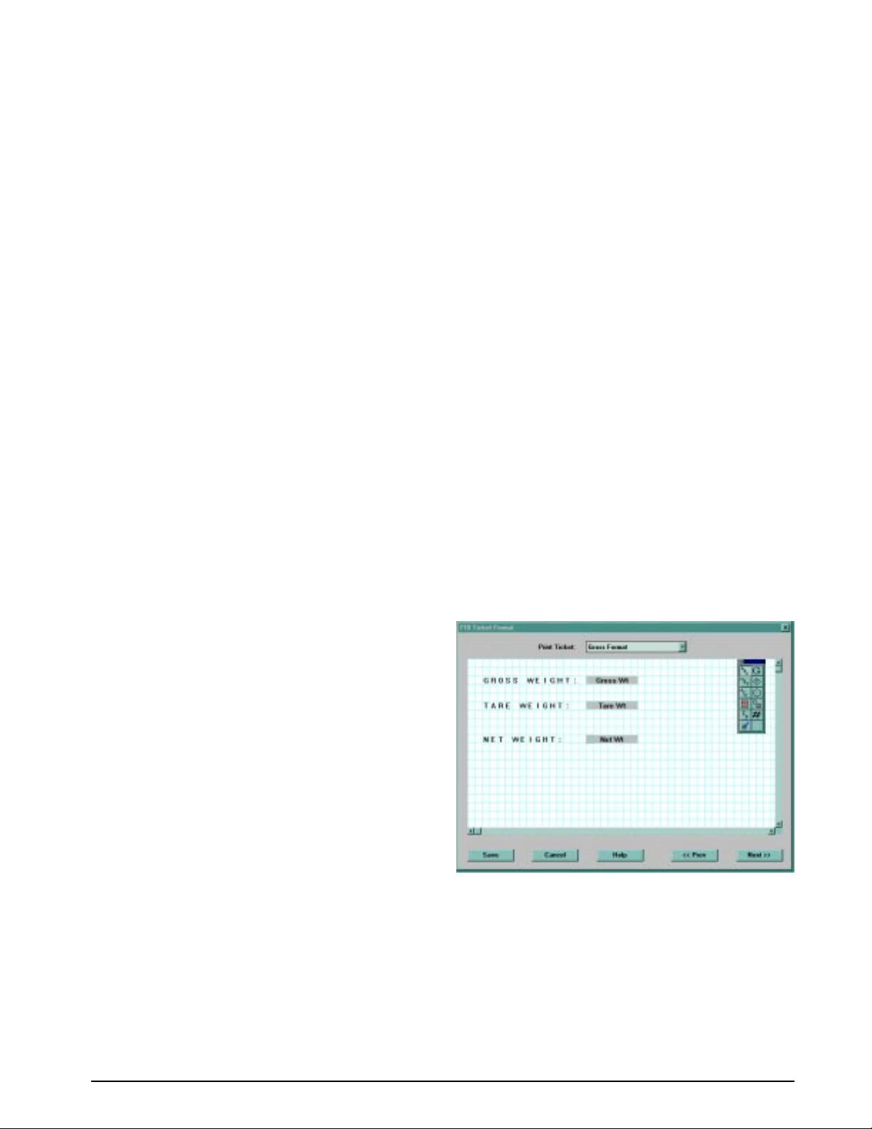
6.3 Customizing Print Formats
The following sections describe procedures for
customizing print formats using the EDP port, the
front panel (PFORMT menu), and the Revolution
configuration utility.
6.3.1 Using the EDP Port
With a personal computer, terminal, or remote
keyboard attached to the IQ plus 710 EDP port, you
can use the EDP command set to customize the print
format strings.
To view the current setting of a format string, type the
name of the print format and press
example, to check the current configuration of the
GFMT format, type GFMT and press
indicator responds by sending the current
configuration for the gross format:
GFMT=<G> GROSS<NL>
To change the format, use the GFMT or NFMT EDP
command followed by an equals sign (=) and the
modified print format string. For example, to add the
name and address of a company to the gross format,
you could send the following EDP command:
GFMT=MOE'S DUMP<NL>2356 EAST HIGHWAY
ROAD<NL>SMALLTOWN<NL2><G> GROSS<NL>
A ticket printed using this format might look like the
following:
MOE'S DUMP
2356 EAST HIGHWAY ROAD
SMALLTOWN
ENTER. For
ENTER. The
6.3.2 Using the Front Panel
If you have no access to equipment for
communication through the EDP port or are working
at a site where such equipment cannot be used, you
can use the PFORMT menu (see Figure 6-2 on page
48) to customize the print formats.
Using the PFORMT menu, you can edit the print
format strings by changing the decimal values of the
ASCII characters in the format string.
NOTE: Lower-case letters and some special characters
cannot be displayed on the IQ plus 710 front panel
(see the ASCII character chart on page 65) and are
shown as blanks. The IQ plus 710 can send or receive
any ASCII character; the character printed depends on
the particular ASCII character set implemented for the
receiving device.
6.3.3 Using Revolution
The Revolution configuration utility provides a print
formatting grid with a tool bar. The grid allows you to
construct the print format without the formatting
commands (<NL> and <SP>) required by the front
panel or EDP command methods. Using Revolution,
you can type text directly into the grid, then select
weight value fields from the tool bar and place them
where you want them to appear on the printed ticket.
Figure 6-1 shows an example of the Revolution print
formatting grid.
1345 LB GROSS
The ticket above could also be formatted by
specifying the company address information in the
HDRFMT ticket format, then substituting the <AE>
command for the address in the GFMT ticket format:
HDRFMT=MOE'S DUMP<NL>2356 EAST HIGHWAY
ROAD<NL>SMALLTOWN<NL2>
GFMT=<AE><G> GROSS<NL>
Figure 6-1. Revolution Print Format Grid
Print Formatting 47
Page 51
DIG INSETPNTSPROGRM PFORMTSERIALCALIBRCONFIG FORMAT
XXXXXXXXXXXXXX
ALGOUT
VERS
GFMT
Press ENTER or to insert a
space before the active character
Decrement ASCII value
of active character
NFMT
characters of format
active character and
Enter numeric ASCII
Press ENTER or to save value
TRWIN
Display first 7
Press CLEAR to delete
the active character
Display and edit
ASCII value
character value
Same as GFMT
Scroll right in format stringScroll left in format string
Increment ASCII value
of active character
SPFMTTRWOUT
EDPFMT
HDRFMT
Figure 6-2. PFORMT Menu, Showing Alphanumeric Character Entry Procedure
48 IQ plus 710 Installation Manual
Page 52
7.0 Truck Modes
The truck in/out modes are used to handle multiple
truck ID numbers and tare weights. Six truck modes
combine stored ID, keyed tare, and value swapping
features in various ways:
Value
Mode Stored IDs Keyed Tares
MODE1 NO YES YES
MODE2 NO NO YES
MODE3 YES YES YES
MODE4 YES NO YES
MODE5 YES YES NO
MODE6 YES NO NO
OFF
Table 7-1. Truck Mode Features
Stored IDs let you keep a database of truck IDs and
Swapping
tare weights in the indicator’s memory. The indicator
can automatically store up to 100 truck IDs and tares;
or it can clear the information after printing a
weigh-out ticket. For example, if the same truck
seldom crosses the scale, it may not be practical to
save its ID number and tare weight. However, if that
same truck crosses the scale many times each day, it’s
much more convenient to store the information in the
indicator memory and recall it when needed. Stored
IDs and tare weights are available in Modes 3, 4, 5,
and 6.
Keyed tares allow you to manually enter the tare
weight using the numeric keypad and the
TARE key.
Keyed tares are available in Modes 1, 3, and 5.
NOTE: Some local regulations require the tare weight
to be read from the scale. If so, don’t use the keyed
tares feature.
Value swapping ensures that the lowest of two
weight values associated with a particular ID number
is entered as the tare weight. For example, if a truck
crosses the scale fully loaded at weigh-in, then
unloads and crosses the scale empty at weigh-out, the
indicator automatically assigns the lesser (empty
truck) weight as the tare. Value swapping is available
in Modes 1, 2, 3, and 4.
T o select a truck in/out mode, press the setup switch to
enter setup mode. Use the navigation keys to go to the
PROGRM menu, then to the TARE100 submenu.
Figure 7-1 shows the structure of the TARE100
submenu.
PROGRM
TARE100
Figure 7-1. TARE100 Truck Mode Selections
7.1 Using the Truck Modes
All the truck in/out modes let you quickly search the
memory for a specific ID number. To do this, key in
the ID number and press the
the number is in memory, it remains on the display.
Otherwise, the indicator displays
to toggle between the ID number and tare weight. To
delete the displayed ID number, press
DISPLAY TARE key. If
NO ID. Press ENTER
CLEAR twice.
MODE 6MODE 5MODE 4MODE 3MODE 2MODE 1OFF
T o scroll through all the stored ID numbers, k e y in any
number and press
DISPLAY TARE, the next number appears on the
press
DISPLAY TARE. Each time you
display.
To print all the stored ID numbers and their associated
tare weights, press
PRINT when an ID number is on
the screen.
Truck Modes 49
Page 53

7.1.1 Modes 1 and 2
In modes 1 and 2, the indicator erases truck ID
numbers and tare weights from memory after the
transaction.
1. The truck moves onto the scale for weigh-in.
2. If keyed tares are enabled (Mode 1), key in
the desired tare weight and press
TARE.
3. Key in an ID number (up to 7 digits) and press
ID. This information remains in memory until
the weigh-out ticket is printed.
4. The indicator prints the weigh-in ticket
(TRWIN format) shown below:
ID. NO. 304812
GROSS 15000. LB INBOUND
08/04/1998 10:24 AM
5. The loaded truck moves onto the scale for
weigh-out.
6. Key in the ID number from the weigh-in
ticket and press
PRINT. The indicator prints a
weigh-out ticket (TRWOUT format) and
automatically clears the information from
memory: If the tare weight is a keyed tare, the
word KEYED is printed after RECALLED on the
tare line.
7.1.3 Single-Transaction Tare Weights and IDs
Version 1.44 supports temporary tare weights for
indicators configured to use stored IDs (TARE100
modes 3–6). This function allows one-time weighing
of trucks without adding the truck ID and tare weight
to the indicator database.
To use this function, enter a truck ID containing a
decimal point, then press
I.D. Tare weights and Truck
IDs entered using decimal truck IDs are erased from
the indicator database when the transaction is
complete.
7.1.2 Modes 3, 4, 5, and 6
In modes 3–6, the indicator stores the tare weights and
ID numbers in memory until you manually erase
them.
1. The truck moves onto the scale for weigh-in.
2. If keyed tares are enabled (Modes 3, 5), key in
the desired tare weight, then press
TARE.
3. Key in an ID number (up to 7 digits) and press
I.D. This information remains in memory until
manually deleted.
4. The indicator prints the weigh-in ticket
(TRWIN format). Truck leaves.
5. The loaded truck moves back onto the scale
for weigh-out.
6. Key in the ID number and press
PRINT. The
indicator prints the weigh-out ticket
(TRWOUT format). If value swapping is
enabled (modes 3 and 4), the lower weight is
always printed as the tare weight.
ID. NO. 304812
GROSS 100000. LB
TARE 15000. LB RECALLED
NET 85000. LB
08/04/1998 10:55 AM
50 IQ plus 710 Installation Manual
Page 54
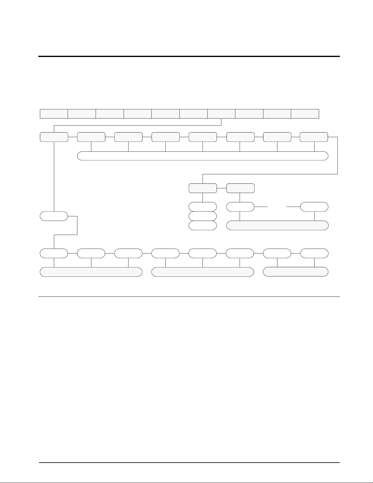
8.0 Setpoints
The IQ plus 710 indicator provides eight programmable setpoints for control of both indicator and external
equipment functions. Setpoints are configured to trip based on specified conditions; tripping the setpoint can be
used to request indicator functions (print, tare, accumulate) or to change the state of a digital output controlling
external equipment.
Figure 8-1 shows the general structure of the SETPNTS menu. See Section 3.2.7 on page 27 for a detailed
description of the SETPNTS menu. The eight setpoint kinds are described in Table 8-1 on page 52.
SETPT1
OFF
GROSSSP NETSP –RELSP
SETPT2 SETPT3 SETPT4 SETPT5 SETPT6 SETPT7 SETPT8
Go to A Go to B
SETPNTS ALGOUTDIG INPROGRM PFORMTSERIALCALIBRCONFIG FORMAT
Same as SETPT1
BATCHNG
OFF
AUTO
MANUAL
PAUSE DELAY WAITSS TIMER CONCUR
Figure 8-1. SETPNTS Menu
SPNAMES
NAME1 NAME16
XXXXXXX
…
setpoint name
VERS
Go to C
8.1 Batch and Continuous Setpoints
IQ plus 710 setpoints can be either continuous or
batch setpoints.
Continuous setpoints are free-running: the indicator
constantly checks the input channel for the setpoint
value at each A/D update. If the input channel weight
reading matches the setpoint value, the indicator sets
the corresponding digital output on.
Batch setpoints are active one at a time, in an ordered
sequence. The IQ plus 710 can use batch setpoints to
control up to eight separate batch processing steps. A
digital output associated with a batch setpoint is on
until the setpoint condition is met, then latched for the
remainder of the batch sequence.
To use batch setpoints, you must activate the
BATCHNG parameter on the SETPNTS menu. This
parameter defines whether a batch sequence is
automatic or manual. AUTO sequences repeat
continuously, while MANUAL sequences require a
BATSTRT digital input or STRTBAT macro
command before restarting. As shown in Table 8-1 on
page 52, GROSSSP, NETSP, and –RELSP setpoint
kinds can be configured as either batch or continuous
setpoints.
The BATCH parameter must also be set on for each
batch setpoint. If the setpoint is defined but the
BATCH parameter is off, the setpoint operates as a
continuous setpoint, even during batch sequences.
Setpoints 51
Page 55

Kind Description Batch Continuous
OFF Setpoint turned off/ignored.
GROSSSP Gross setpoint. Trips when the current gross weight matches this value. √√
NETSP Net setpoint. Trips when the current net weight matches this value. √√
–RELSP Negative relative setpoint. Trips at a specific value below the referenced
√√
setpoint.
PAUSE Pauses the batch sequence indefinitely. Operator must activate the BATSTRT
√
digital input to continue processing.
DELAY Delays the batch sequence for a specified time. The length of the delay (in
√
tenths of a second) is specified on the Value parameter.
WAITSS Wait for standstill. Pauses the batch sequence until the scale is at standstill. √
TIMER Tracks the progress of a batch sequence based on a timer.
√
The timer value, specified in tenths of a second on the VALUE parameter,
determines the length of time allowed between start and end setpoints. The
indicator START and END parameters are used to specify the start and end
setpoints. If the END setpoint is not reached before the timer expires, the digital
output associated with this setpoint is activated.
CONCUR Allows a digital output to remain active over a specified portion of the batch
√
sequence. Two types of concur setpoints can be configured:
Type 1: The digital output associated with this setpoint becomes active when
the START setpoint becomes the current batch step and remains active until
the END setpoint becomes the current batch step.
Type 2: The digital output associated with this setpoint becomes active when
the START setpoint becomes the current batch step and remains active until a
timer expires.
The indicator START and END parameters specify the start and end setpoints.
The timer value is specified in tenths of a second on the VALUE parameter.
Table 8-1. Setpoint Kinds
52 IQ plus 710 Installation Manual
Page 56

8.2 Batching Examples
8.2.1 Example 1
The following example uses seven setpoints to
dispense material from a container in 100
and to automatically refill the container when its
weight drops below 300
LB.
Digital inputs 1 and 2 are assigned to batch start and
batch run functions: BATRUN must be on (low)
before the BATSTRT input starts the batch.
DIGIN1=BATSTRT
DIGIN2=BATRUN
BATCHNG=MANUAL
Setpoint 1 ensures that the container has enough
material to start the batch. If the container weight is
LB or higher, setpoint 1 is tripped.
300
SETPOINT=1
KIND=GROSSSP
VALUE=300
TRIP=HIGHER
BATCH=ON
ACCESS=ON
Setpoint 2 waits for standstill, then performs a tare to
put the indicator into net mode.
SETPOINT=2
KIND=WAITSS
PSHTARE=ON
ACCESS=ON
Setpoint 3 is used as a reference (relative setpoint) for
setpoint 4 and is tripped with a weight of 0±2
SETPOINT=3
KIND=NETSP
VALUE=0
TRIP=HIGHER
BATCH=OFF
ACCESS=ON
Setpoint 4 is used to dispense material from the
container. When the container weight falls to 100
less than its weight at the relative setpoint (setpoint 3),
digital output 1 is set off.
SETPOINT=4
KIND=–RELSP
VALUE=100
TRIP=LOW
BATCH=ON
ACCESS=ON
DIGOUT=1
RELNUM=3
LB batches
LB.
LB
Setpoint 5 is a short (.2-second) delay used to provide
an end point for a timer setpoint (setpoint 6).
SETPOINT=5
KIND=DELAY
VALUE=2
ACCESS=ON
Setpoint 6 is used to ensure that the operation
performed in setpoint 4 is completed within 10
seconds. The START and END parameters identify
the setpoints monitored by the timer. If the timer
expires before setpoint 5 starts, digital output 4 is
turned on as an alarm to signal a process fault.
SETPOINT=6
KIND=TIMER
VALUE=100
START=4
END=5
ACCESS=ON
DIGOUT=4
Setpoint 7 is a continuous setpoint, used to maintain
the material level in the container. When the container
weight falls below 300
LB (VALUE – HYSTERESIS),
digital output 2 is turned on and the container refilled
to 1000
LB.
SETPOINT=7
KIND=GROSSSP
VALUE=300
TRIP=HIGHER
HYSTER=700
BATCH=ON
ACCESS=ON
DIGOUT=2
The ACCESS parameter should be set ON when
creating and testing batch routines. Once the batching
routine is complete and ready for production,
ACCESS can be set to OFF to prevent changes to the
configured setpoint value, or to HIDE to prevent
changing or viewing the value.
Setpoints 53
Page 57

8.2.2 Example 2
The following example uses seven setpoints to control
a two-speed fill operation where both fast and slow
feeds are on simultaneously.
Digital inputs 1 and 2 are assigned to batch start and
batch run functions: BATRUN must be on (low)
before the BATSTRT input starts the batch.
DIGIN1=BATSTRT
DIGIN2=BATRUN
BATCHNG=MANUAL
Setpoint 1 ensures that the scale is empty (0±2 LB).
SETPOINT=1
KIND=GROSSSP
VALUE=0
TRIP=INBAND
BANDVAL=2
BATCH=ON
Setpoint 5 controls the slow fill operation. When the
net weight reaches 200
LB, the slow fill is stopped
(see Setpoint 7), the indicator waits for standstill and
performs a push print operation using the SPFMT
ticket format.
SETPOINT=5
KIND=NETSP
VALUE=200
PSHPRINT=WAITSS
TRIP=HIGHER
BATCH=ON
DIGOUT=2
Setpoint 6 is a short (.2-second) delay used to provide
an end point for a concur setpoint (setpoint 7).
SETPOINT=6
KIND=DELAY
VALUE=2
Setpoint 2 checks for the weight of a container (≥ 5
LB) placed on the scale.
SETPOINT=2
KIND=GROSSSP
VALUE=5
TRIP=HIGHER
BATCH=ON
Setpoint 3 waits for standstill, then tares the container
weight, placing the indicator in net mode.
SETPOINT=3
KIND=WAITSS
PSHTARE=ON
Setpoint 4 starts the fast fill operation. When the net
weight reaches 175
LB, the setpoint trips and digital
output 1 is set off.
SETPOINT=4
KIND=NETSP
VALUE=175
TRIP=HIGHER
BATCH=ON
DIGOUT=1
Setpoint 7 is a continuous setpoint, used to allow the
slow feed output to be on at the same time as the fast
fill. The slow fill output (digital output 2) is turned on
when setpoint 4 (fast fill) starts and remains on until
setpoint 5 (slow fill) reaches 200
SETPOINT=7
KIND=CONCUR
VALUE=0
START=4
END=5
DIGOUT=2
LB.
54 IQ plus 710 Installation Manual
Page 58
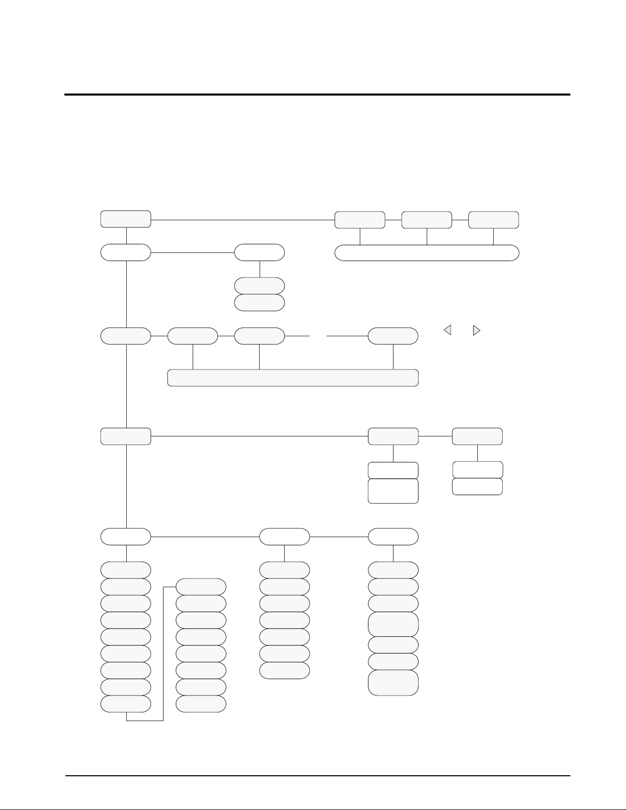
9.0 Macro Programming
Up to four macro sequences can be programmed for the IQ plus 710 indicator. Each macro provides a simulation
of up to 30 front panel key presses and can be used to provide single-key, automated operation of a number of
processes, including operator identification, prompts, setpoint editing, and batch control.
9.1 Using the Macro Submenu
Macros can be programmed using the front panel, EDP commands, or the Revolution configuration utility.
Figure 9-1 shows the structure of the MACRO submenu under the PROGRM menu; Table 9-1 on page 56
describes each of the MACRO submenu parameters.
MACRO1
EDIT STRTBAT
OFF
ON
STEP1 STEP2 STEP3 STEP30
same as STEP1
Press F3 to insert a step before the current step
Press F4 to delete the current macro step
Press CLEAR to clear the current macro step
KEY
MACRO2 MACRO3 MACRO4
…
NAME
NONE
NAME1 –
NAME60
same as MACRO1
Use and to scroll left
and right through macro steps
TIMEOUT
0
number
KEYPAD PSEUDO PAUSREL
OFF
ZERO
G/N
TARE
UNITS
PRINT
ID
SETPT
T/D
ESCAPE
ALPHA
ACCUM
DSPTAR
CLEAR
ENTER
0–9
DP
GROSS
NET
PRIM
SEC
TIME
DATE
CLRCN
MAJORKY
MOTION
COZ
DIGIN1–
DIGIN8
AZTRACK
TIMER
COMPAR1–
COMPAR8
Figure 9-1. Macro Submenu under PROGRM Menu
Macro Programming 55
Page 59
PROGRM Menu
Parameter Choices Description
Level 2 MACRO submenu
MACRO1
MACRO2
MACRO3
MACRO4
Level 3 MACRO submenu
EDIT macro sequence Create or display a macro sequence
STRTBAT OFF
Level 4 MACRO submenu
STEP1 –
STEP30
Level 5 MACRO submenu
KEY KEYPAD
NAME NONE
TIMEOUT number If TIMER is specified for the PAUSREL parameter, specify a timer value in the range
Level 6 MACRO submenu
KEYPAD OFF
PSEUDO GROSS
EDIT
STRTBAT
ON
KEY
NAME
TIMEOUT
PSEUDO
PAUSREL
NAME1 – NAME60
ZERO
G/N
TARE
UNITS
PRINT
ID
SETPT
T/D
ESCAPE
ALPHA
ACCUM
DSPTAR
CLEAR
ENTER
0–9
DP
NET
PRIM
SEC
TIME
DATE
CLRCN
Configure macros
Specifies whether a batch sequence is automatically started when the macro
sequence ends. STRTBAT=ON is functionally equivalent to the BATSTRT digital
input.
Select macro step
Specifies whether the keystroke simulated by the macro is an actual keypad key, a
pseudo key, or a pause release.
Specifies the text, if any, shown on the secondary display during macro execution.
NAME1 through NAME60 are specified on the PROMPTS parameter.
0–65535, in 0.1-second intervals. For example, specify TIMER=150 to insert a
15-second pause.
Select front panel key simulated by this macro step.
The PSEUDO parameter allows simulation of a pseudo key for the macro step.
Pseudo keys are keypad functions not represented by an actual front panel key.
For example, the PRIM pseudo key displays the primary units configured for the
indicator, but there is no actual primary units key on the front panel. The PRIM and
SEC pseudo keys are used to explicitly request primary or secondary units display;
the UNITS front panel key toggles between primary and secondary units,
depending on which is displayed at the time the key is pressed.
Table 9-1. MACRO Submenu Parameters (PROGRM Menu)
56 IQ plus 710 Installation Manual
Page 60
PROGRM Menu
Parameter Choices Description
PAUSREL MAJORKY
MOTION
COZ
DIGIN1 – DIGIN8
AZTRACK
TIMER
COMPAR1 – COMPAR8
The PAUSEREL parameter inserts a pause in the macro sequence that is released
when the specified condition is met. The value specified for this parameter
determines when the pause is released:
MAJORKY: When any of the five major keys is pressed
MOTION: When scale reaches standstill
COZ: When scale reaches center of zero
DIGIN1–DIGIN8: When DIGINx goes active
AZTRACK: When scale is within zero track band
TIMER: When timer expires (timer value is specified on TIMEOUT parameter)
COMPAR1 – COMPAR8: When the setpoint x (1–8) changes state
Table 9-1. MACRO Submenu Parameters (PROGRM Menu)
9.2 Macro Programming Examples
The macro shown below is started when the operator
To prevent injury and equipment
Warning
damage, always test macros and
batching routines thoroughly before
connecting the indicator to a live
system.
9.2.1 Example 1
The following example uses a macro to provide
operator prompts for a simple container filling
procedure. The single setpoint is used to check for a
full container; when tripped, the setpoint releases the
pause in step 3 of the macro.
With the indicator in setup mode, the following EDP
commands are sent to program the setpoint and assign
prompts used by the macro.
SETPOINT=1
KIND=NETSP
VALUE=200
TRIP=HIGHER
BATCH=OFF
DIGOUT=NONE
BATCHNG=OFF
PROMPT#1=ADD BOX
PROMPT#2=ADD MATERIAL
PROMPT#3=REMOVE BOX
NOTE: Prompts are assigned using the PROMPT#n
EDP command or the PROMPTS parameter on the
PROGRM menu. Prompts are recalled for display
during macro execution using the NAME.n EDP
parameter or the NAME parameter under the macro
submenu.
presses the F1 macro key:
MACRO 1
MACRO1.K01=PAUSREL.MOTION
MACRO1.K01=NAME.1
MACRO1.K02=KTARE
MACRO1.K03=PAUSREL.COMPAR1
MACRO1.K03=NAME.2
MACRO1.K04=KPRINT
MACRO1.K05=PAUSREL.COZ
MACRO1.K05=NAME.3
1. The first macro step displays the prompt ADD
BOX on the secondary display and waits for
scale motion caused by the operator placing
the box on the scale. When scale motion
stops, the pause is released and the macro
continues.
2. The macro performs a tare operation, taring
the box weight and placing the indicator in net
mode.
3. The secondary display prompts the operator
ADD MATERIAL. The prompt is held on the
to
display until setpoint 1 changes state
(COMPAR1). When the setpoint trips, the
pause is released.
4. The macro performs a print operation using
the NFMT ticket format.
5. The secondary display prompts the operator
REMOVE BOX. The prompt is held on the
to
display until the gross weight on the scale
goes to zero.
Macro Programming 57
Page 61

9.2.2 Example 2
The following example uses a combination of macros
and batch routines to control a filling operation. The
operation includes filling a container with two
ingredients, pausing the batch for a mixing operation,
then adding a third ingredient.
With the indicator in setup mode, the following EDP
commands are sent to program the setpoints and
assign prompts used by the macros.
SETPOINT=1
KIND=NETSP
VALUE=5
TRIP=HIGHER
BATCH=ON
DIGOUT=1
SETPOINT=2
KIND=NETSP
VALUE=10
TRIP=HIGHER
BATCH=ON
DIGOUT=2
Digital input 1 is connected to a batching switch and
configured as a BATRUN input. The batching switch
must be on to enable the STRTBAT (batch start)
commands in the macros.
Digital inputs 2–4 are wired from digital outputs 3, 5,
and 6: When the setpoints associated with the digital
outputs are tripped, the output activates the digital
input to start the next macro.
DIGIN1=BATRUN
DIGIN2=KF2
DIGIN3=KF3
DIGIN4=KF1
The macros shown below begin when the operator
presses the F1 macro key:
1. MACRO 1 displays the prompt
ADD BUCKET
on the secondary display and waits for scale
motion caused by the operator placing the
bucket on the scale. When scale motion stops,
the pause is released and the macro continues.
SETPOINT=3
KIND=PAUSE
DIGOUT=3
SETPOINT=4
KIND=NETSP
VALUE=15
TRIP=HIGHER
BATCH=ON
DIGOUT=4
SETPOINT=5
KIND=WAITSS
PSHPRINT=ON
DIGOUT=NONE
SETPOINT=6
KIND=PAUSE
DIGOUT=5
SETPOINT=7
KIND=GROSSSP
VALUE=0
TRIP=HIGHER
BATCH=ON
DIGOUT=6
MACRO 1
MACRO1.STRTBAT=ON
MACRO1.K01=PAUSREL.MOTION
MACRO1.K01=NAME.1
MACRO1.K02=KTARE
2. The macro performs a tare operation, taring
the bucket weight and placing the indicator in
net mode.
3. The
STRTBAT=ON macro statement starts the
batch once the tare operation is complete.
4. The batch starts, adding Ingredient A until the
bucket net weight reaches 5 LB (see
SETPOINT 1 configuration above). When
setpoint 1 trips, DIGOUT 1 goes off and
Ingredient A stops filling.
5. Setpoint 2 adds Ingredient B until the bucket
net weight reaches 10 LB (see
SETPOINT 2
configuration above). When setpoint 2 trips,
DIGOUT 2 goes off and Ingredient B stops
filling.
6. Setpoint 3 is a pause setpoint used to activate
digital output 3. Digital output 3 is wired to
DIGIN2 as a KF2 (press MACRO key F2)
input and starts MACRO 2.
BATCHNG=MANUAL
PROMPT#1=ADD BUCKET
PROMPT#2=MIX PAINT
PROMPT#3=REMOVE BUCKET
58 IQ plus 710 Installation Manual
Page 62

MACRO 2
MACRO2.STRTBAT=ON
MACRO2.K01=PAUSREL.MOTION
MACRO2.K01=NAME.2
7. MACRO 2 displays the prompt MIX PAINT on
the secondary display and waits for scale
motion caused by the operator mixing the
paint. When scale motion stops, the pause is
released and the macro restarts the batch
sequence at Setpoint 4.
8. Setpoint 4 adds Ingredient C until the bucket
net weight reaches 15 LB (see
SETPOINT 4
configuration).When setpoint 4 trips, DIGOUT
4 goes off and Ingredient C stops filling.
9. Setpoint 5 waits for standstill then prints
ticket using the SPFMT ticket format.
10. Setpoint 6 is a pause setpoint used to activate
digital output 5. Digital output 5 is wired to
DIGIN3 as a KF3 (press MACRO key F3
input and starts MACRO 3.
MACRO 3
MACRO3.STRTBAT=ON
MACRO3.K01=PAUSREL.COZ
MACRO3.K01=NAME.3
MACRO3.K02=KZERO
11. MACRO 3 displays the prompt REMOVE
BUCKET on the secondary display and waits
until the gross weight on the scale goes to
zero. When the scale reaches center of zero,
the pause is released and the macro zeroes the
scale (KZERO command) and restarts the
batch at Setpoint 7.
12. Setpoint 7 checks that the gross weight on the
scale is zero, then activates digital output 6.
Digital output 6 is wired to DIGIN4 as a KF1
(press MACRO key F1) input and starts
MACRO 1 again.
Macro Programming 59
Page 63

9.2.3 Example 3
The following example describes how a series of
macros can be programmed to provide single-key
reprogramming of setpoint values. Table 9-2 shows
the values of three setpoints used to fill different
proportions of ingredients for three products.
Setpoint Values PRODUCT A PRODUCT B PRODUCT C
INGRED 1 100 150 110
INGRED 2 200 250 210
INGRED 3 300 280 290
Table 9-2. Setpoint Values for Three-Ingredient Products
With the indicator in setup mode, the following EDP
commands are sent to program three gross setpoints to
their initial values and assign setpoint names used by
the macros.
SETPOINT=1
KIND=GROSSSP
VALUE=100
TRIP=HIGHER
BATCH=ON
ACCESS=ON
NAME=1
DIGOUT=1
SETPOINT=2
KIND=GROSSSP
VALUE=200
TRIP=HIGHER
BATCH=ON
ACCESS=ON
NAME=2
DIGOUT=2
SETPOINT=3
KIND=GROSSSP
VALUE=300
TRIP=HIGHER
BATCH=ON
ACCESS=ON
NAME=3
DIGOUT=3
BATCHNG=MANUAL
PROMPT#1=INGRED 1
PROMPT#2=INGRED 2
PROMPT#3=INGRED 3
PROMPT#4=LOAD PRODUCT A
PROMPT#5=LOAD PRODUCT B
PROMPT#6=LOAD PRODUCT C
Next, three macros are programmed to allow
reassignment of the setpoint values for each of the
three products.
Each macro uses the
setpoint value: the
call up setpoint 1; press
setpoint 2. Each time the
SETPOINT key to change the
SETPOINT key is pressed once to
SETPOINT again to call up
SETPOINT key is pressed,
the value of the next setpoint is shown.
The three macros listed below reset the setpoint values
for PRODUCT A, PRODUCT B, and PRODUCT C.
MACRO1 sets the values of setpoints 1–3 to the initial
values listed above.
NOTES:
• When the front panel
SETPOINT key is
pressed, the indicator normally waits before
showing the setpoint value. To accommodate
this delay, a timer is inserted before each
setpoint value entry.
• Pause release parameters (PAUSREL,
NAME, TIMEOUT) are entered on separate
EDP commands, but are treated as a single
keystroke.
MACRO 1
MACRO1.K01=PAUSREL.TIMER
MACRO1.K01=NAME.4
MACRO1.K01=TIMEOUT.100
MACRO1.K02=KSETPOINT
MACRO1.K03=PAUSREL.TIMER
MACRO1.K03=NAME.1
MACRO1.K03=TIMEOUT.35
MACRO1.K04=K1
MACRO1.K05=K0
MACRO1.K06=K0
MACRO1.K07=KENTER
MACRO1.K08=KSETPOINT
MACRO1.K09=PAUSREL.TIMER
MACRO1.K09=NAME.2
MACRO1.K09=TIMEOUT.35
MACRO1.K10=K2
MACRO1.K11=K0
MACRO1.K12=K0
MACRO1.K13=KENTER
MACRO1.K14=KSETPOINT
MACRO1.K15=PAUSREL.TIMER
MACRO1.K15=NAME.3
MACRO1.K15=TIMEOUT.35
MACRO1.K16=K3
MACRO1.K17=K0
MACRO1.K18=K0
MACRO1.K19=KENTER
60 IQ plus 710 Installation Manual
Page 64

MACRO 2
MACRO2.K01=PAUSREL.TIMER
MACRO2.K01=NAME.5
MACRO2.K01=TIMEOUT.100
MACRO 3
MACRO3.K01=PAUSREL.TIMER
MACRO3.K01=NAME.6
MACRO3.K01=TIMEOUT.100
MACRO2.K02=KSETPOINT
MACRO2.K03=PAUSREL.TIMER
MACRO2.K03=NAME.1
MACRO2.K03=TIMEOUT.35
MACRO2.K04=K1
MACRO2.K05=K5
MACRO2.K06=K0
MACRO2.K07=KENTER
MACRO2.K08=KSETPOINT
MACRO2.K09=PAUSREL.TIMER
MACRO2.K09=NAME.2
MACRO2.K09=TIMEOUT.35
MACRO2.K10=K2
MACRO2.K11=K5
MACRO2.K12=K0
MACRO2.K13=KENTER
MACRO2.K14=KSETPOINT
MACRO2.K15=PAUSREL.TIMER
MACRO2.K15=NAME.3
MACRO2.K15=TIMEOUT.35
MACRO2.K16=K2
MACRO2.K17=K8
MACRO2.K18=K0
MACRO2.K19=KENTER
MACRO3.K02=KSETPOINT
MACRO3.K03=PAUSREL.TIMER
MACRO3.K03=NAME.1
MACRO3.K03=TIMEOUT.35
MACRO3.K04=K1
MACRO3.K05=K1
MACRO3.K06=K0
MACRO3.K07=KENTER
MACRO3.K08=KSETPOINT
MACRO3.K09=PAUSREL.TIMER
MACRO3.K09=NAME.2
MACRO3.K09=TIMEOUT.35
MACRO3.K10=K2
MACRO3.K11=K1
MACRO3.K12=K0
MACRO3.K13=KENTER
MACRO3.K14=KSETPOINT
MACRO3.K15=PAUSREL.TIMER
MACRO3.K15=NAME.3
MACRO3.K15=TIMEOUT.35
MACRO3.K16=K2
MACRO3.K17=K9
MACRO3.K18=K0
MACRO3.K19=KENTER
Macro Programming 61
Page 65
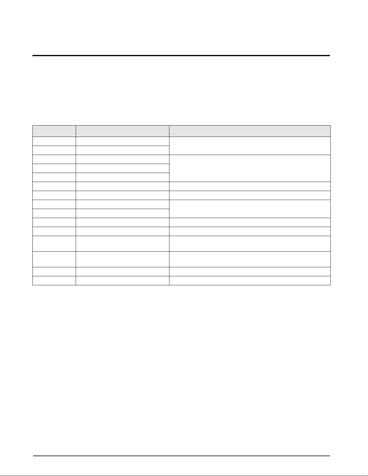
10.0 Appendix
10.1 Error Messages
The IQ plus 710 indicator provides a number of error messages. When an error occurs, the message is shown on
the indicator display . Error conditions can also be checked remotely by using the XE EDP command as described
in Section 10.1.2.
10.1.1 Displayed Error Messages
The IQ plus 710 provides a number of front panel error messages to assist in problem diagnosis. Table 10-1 lists
these messages and their meanings.
Error Message Description Solution
E A/D A/D physical error Call Rice Lake Weighing Systems (RLWS) Service.
E EEROM EEPROM physical error
E VIREE Virgin EEPROM Use TEST menu to perform DEFLT (restore defaults) procedure,
E PCKSM Parameter checksum error
EFCKSM Printer format checksum error
E LCKSM Load cell calibration checksum error Recalibrate scale.
E ACKSM A/D calibration checksum error A/D converter requires recalibration. Call RLWS Service.
E IDATA Internal RAM test error Call RLWS Service.
E XDATA External RAM test error
E REF A/D reference error A/D converter requires recalibration. Call RLWS Service.
OVERFL Overflow error Weight value too large to be displayed.
REG ERR Battery fault Battery weak or not installed. Replace battery then use TEST menu
ACC ERR Accumulator overflow error Press ACCUM to display accumulator value, then press CLEAR
------ Gross > overload limit Gross value exceeds overload limit. Check configuration.
______ A/D underrange A/D reading < –4 mV. Check scale for binding or damage.
then recalibrate scale.
to perform CLR NV (clear non-volatile storage) procedure.
twice to clear the accumulator.
Table 10-1. IQ plus 710 Error Messages
10.1.2 Using the XE EDP Command
The XE EDP command can be used to remotely query the IQ plus 710 for the error conditions shown on the front
panel. The XE command returns two 5-digit numbers in the format:
xxxxx yyyyy
where xxxxx contains a decimal representation of any existing error conditions as described in Table 10-2.
If more than one error condition exists, the number returned is the sum of the values representing the error
conditions. For example, if the XE command returns the number 288, this value represents the sum of an A/D
reference error (256) and an A/D calibration checksum error (32).
The second number returned (
whether the test for the error condition was run. For example, the value
yyyyy) uses the same bit assignments as shown in Table 10-2 on page 63 to indicate
yyyyy = 50687 represents the decimal
equivalent of the binary value 1100 0101 1111 1111. Using the bit assignments in Table 10-2, this indicates all
tests were run except the accumulator overflow and NV register checksum tests.
62 IQ plus 710 Installation Manual
Page 66

Error
Code
0 No error 0000 0000 0000 0000
1 A/D physical error 0000 0000 0000 0001
2 EEPROM physical error 0000 0000 0000 0010
4 Virgin EEPROM 0000 0000 0000 0100
8 Parameter checksum error 0000 0000 0000 1000
16 Load cell calibration
checksum error
32 A/D calibration checksum
error
64 Internal RAM data error 0000 0000 0100 0000
128 External RAM data error 0000 0000 1000 0000
256 A/D reference error 0000 0001 0000 0000
512 NV register checksum error 0000 0010 0000 0000
1024 Printer format checksum
error
2048 not assigned 0000 1000 0000 0000
4096 Accumulator overflow error 0001 0000 0000 0000
8192 not assigned 0010 0000 0000 0000
16384 A/D underrange 0100 0000 0000 0000
32768 Gross > overload limit 1000 0000 0000 0000
Description Binary Value
0000 0000 0001 0000
0000 0000 0010 0000
0000 0100 0000 0000
10.2 Status Messages
Two EDP commands, P and ZZ, can be used to
provide status about the indicator.
• The P EDP command returns whatever is
currently shown in the indicator’s primary
display area.
• The ZZ EDP command returns whatever is
currently shown in both the primary and
secondary displays. Depending on the type of
device used to receive data from the indicator,
the standstill and center of zero symbols may
be shown as spaces or as special characters.
The ZZ command returns information in the
following format:
PPPPPPP uu ssssssssssssssss
where:
PPPPPPP is the information shown on
•
the primary display
uu is the 2-digit units annunciator
•
ssssssssssssssss is the contents of the
•
secondary display
If the indicator is in an underrange or overload
condition, the weight value is replaced with
(overload) or :::::: (underrange).
&&&&&&
Table 10-2. Error Codes Returned on XE Command
Appendix 63
Page 67
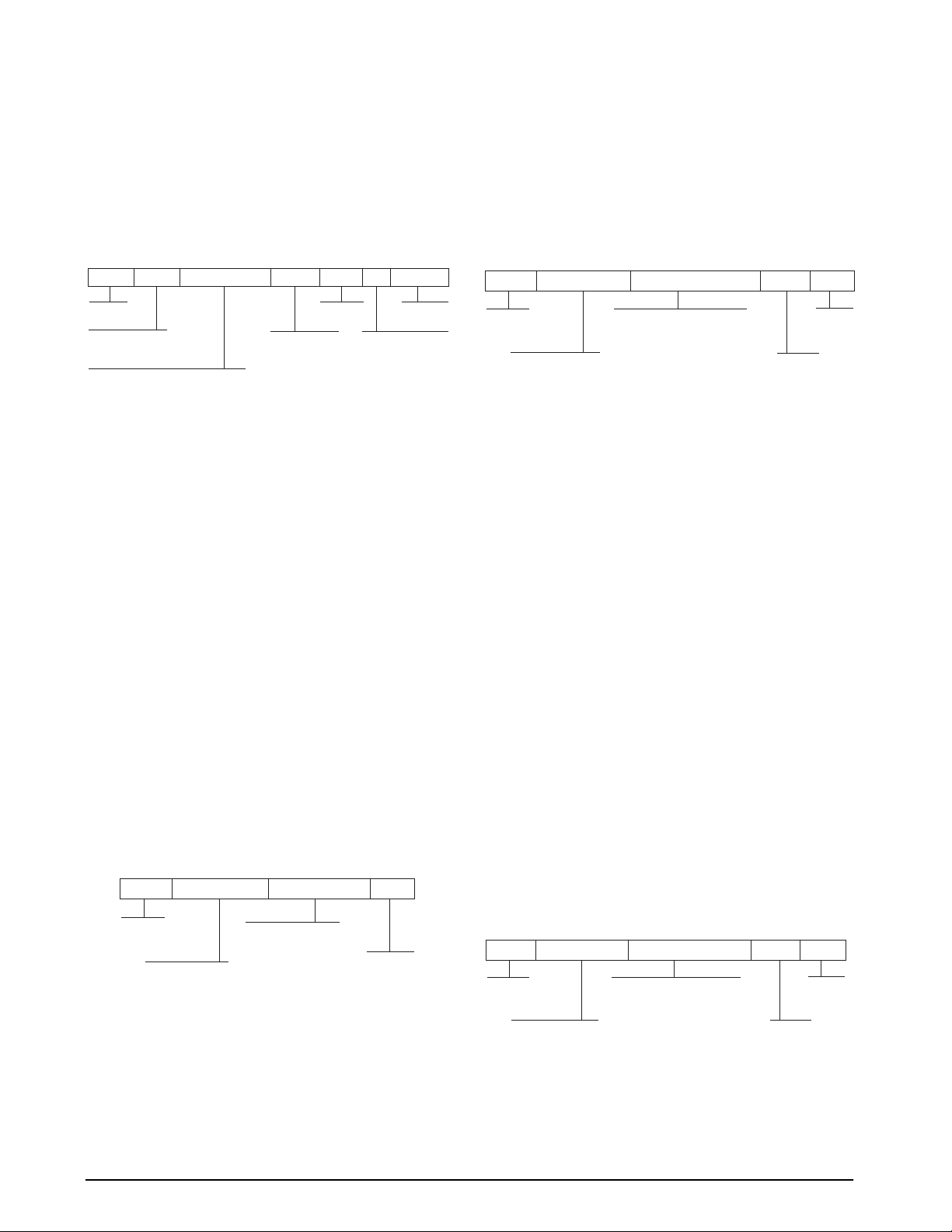
10.3 Data Formats
<STX> <ADDRESS> <DEMAND DATA> <ETX> <CR>
ASCII 02
decimal
Address of the
transmitting indicator
Response commands from
indicator:
<first line> <EOL>
<additional lines> <EOL>
<last line> <EOL>
where EOL = <CR> or <CR> <LF>
(set by TERMIN parameter on the
SERIAL menu)
ASCII 13
decimal
ASCII 03
decimal
10.3.1 Continuous Output Serial Data Format
If continuous transmission is configured for the EDP
or printer port (STREAM parameter on the SERIAL
menu), the IQ plus 710 sends data using the
Consolidated Controls serial data format shown in
Figure 10-1:
<STX> <POL> <wwwwwww> <UNIT> <G/N> <S> <TERM>
ASCII 02
decimal
Polarity:
<space> = Positive
<–> = Negative
Weight: 7 digits, right-justified, dummy
zeroes, decimal point with no leading
zeroes except for leading zero immediately
preceding the decimal point. Leading
zeroes transmitted as spaces.
L = pounds
K = kilograms
T = short tons (TN)
G = grams
<space> = OZ, GN,
G = Gross
N = Net
T, LT, TROYOZ,
TROYLB, NONE
<CR> <LF>
or <CR>
Status:
<space> = valid
I = Invalid
M = Motion
O = Over/under range
Figure 10-1. Continuous Output Serial Data Format
10.3.2 Demand Output Serial Data Format
When demand mode is configured for the EDP or
printer port in the setup menus (PRNDEST on the
SERIAL menu), the IQ plus 710 uses a data string
formatted for a basic ticket printout. The particular
ticket format printed depends on the indicator
configuration.
You can use the EDP port or keypad to fully
customize the ticket to work with a wide variety of
printers, scoreboard displays, and other remote
equipment. See Section 6.0 on page 45 for more
information on custom print formats.
10.3.3 RS-485 Data Formats
The IQ plus 710 has a built-in RS-485 software
protocol which is enabled when you assign a non-zero
address to the indicator. Valid RS-485 addresses must
be in the range 1–255; the address is specified on the
ADDRESS parameter on the SERIAL menu.
All remote commands are initiated using the data
format shown in Figure 10-2:
<STX> <ADDRESS> <COMMAND> <CR>
ASCII 02
decimal
Address of the
receiving indicator
Figure 10-2. RS-485 Send Data Format
EDP serial command
NOTE: Host must send <CR>, not
<CR> <LF>. Failure to use <CR>
renders all indicators unable to
respond to serial commands
ASCII
13 decimal
If the initiating device address matches the port
address of an IQ plus 710 on the RS-485 network, that
indicator responds. For example, with demand
outputs, or in response to a KPRINT command, the
responding indicator uses the format shown in
Figure 10-3:
Figure 10-3. RS-485 Respond Data Format
Example:
To send the KPRINT command from an
ASCII terminal to an indicator at address 65 (decimal)
on the RS-485 network, use the format shown in
Figure 10-2.
• The keyboard equivalent for the start-of-text
STX) character is CONTROL-B (see
(
Table 10-3 on page 65).
• The indicator address (65) is represented by
an upper case “A”.
• The carriage return (CR) character is
generated by pressing the
ENTER key.
Therefore, to send the KPRINT command to the
indicator at address 65, enter the following at the
terminal:
CONTROL-B, A, K, P, R, I, N, T, ENTER.
The indicator responds with the format shown in
Figure 10-3:
<STX> A SCALE #1 <EOL>
GROSS 1699 LB<EOL>
08/20/1998 10:05 AM<EOL>
<ETX> <CR>
If continuous transmission is configured for the EDP
port (STREAM parameter on the SERIAL menu), the
IQ plus 710 sends data using the data format shown in
Figure 10-4:
<STX> <ADDRESS> <STREAM DATA> <ETX> <CR>
ASCII 02
decimal
transmitting indicator
Address of the
Response commands from
indicator:
<STX> <POL> <wwwwwww>
<L/K> <G/N> <S> <EOL>
NOTE : This is the Consolidated
Controls continuous data format
ASCII 03
decimal
ASCII 13
decimal
64 IQ plus 710 Installation Manual
Figure 10-4. RS-485 Continuous Data Format
Page 68

10.4 ASCII Character Chart
Use the decimal values for ASCII characters listed in Tables 10-3 and 10-4 when specifying print format strings
on the IQ plus 710 PFORMT menu. The actual character printed depends on the character mapping used by the
output device.
The IQ plus 710 can send or receive any ASCII character value (decimal 0–255). Due to limitations of the
indicator display, some characters cannot be shown.
Control ASCII Dec Hex ASCII Dec Hex ASCII Dec Hex ASCII Dec Hex
Ctrl-@ NUL 00 00 space 32 20 @ 64 40 ` 96 60
Ctrl-A SOH 01 01 ! 33 21 A 65 41 a 97 61
Ctrl-B STX 02 02 “ 34 22 B 66 42 b 98 62
Ctrl-C ETX 03 03 # 35 23 C 67 43 c 99 63
Ctrl-D EOT 04 04 $ 36 24 D 68 44 d 100 64
Ctrl-E ENQ 05 05 % 37 25 E 69 45 e 101 65
Ctrl-F ACK 06 06 & 38 26 F 70 46 f 102 66
Ctrl-G BEL 07 07 ’ 39 27 G 71 47 g 103 67
Ctrl-H BS 08 08 ( 40 28 H 72 48 h 104 68
Ctrl-I HT 09 09 ) 41 29 I 73 49 i 105 69
Ctrl-J LF 10 0A * 42 2A J 74 4A j 106 6A
Ctrl-K VT 11 0B + 43 2B K 75 4B k 107 6B
Ctrl-L FF 12 0C , 44 2C L 76 4C l 108 6C
Ctrl-M CR 13 0D - 45 2D M 77 4D m 109 6D
Ctrl-N SO 14 0E . 46 2E N 78 4E n 110 6E
Ctrl-O SI 15 0F / 47 2F O 79 4F o 111 6F
Ctrl-P DLE 16 10 0 48 30 P 80 50 p 112 70
Ctrl-Q DC1 17 11 1 49 31 Q 81 51 q 113 71
Ctrl-R DC2 18 12 2 50 32 R 82 52 r 114 72
Ctrl-S DC3 19 13 3 51 33 S 83 53 s 115 73
Ctrl-T DC4 20 14 4 52 34 T 84 54 t 116 74
Ctrl-U NAK 21 15 5 53 35 U 85 55 u 117 75
Ctrl-V SYN 22 16 6 54 36 V 86 56 v 118 76
Ctrl-W ETB 23 17 7 55 37 W 87 57 w 119 77
Ctrl-X CAN 24 18 8 56 38 X 88 58 x 120 78
Ctrl-Y EM 25 19 9 57 39 Y 89 59 y 121 79
Ctrl-Z SUB 26 1A : 58 3A Z 90 5A z 122 7A
Ctrl-[ ESC 27 1B ; 59 3B [ 91 5B { 123 7B
Ctrl-\ FS 28 1C < 60 3C \ 92 5C | 124 7C
Ctrl-] GS 29 1D = 61 3D ] 93 5D } 125 7D
Ctrl-^ RS 30 1E > 62 3E ^ 94 5E ~ 126 7E
Ctrl-_ US 31 1F ? 63 3F _ 95 5F DEL 127 7F
Table 10-3. ASCII Character Chart (Part 1)
Appendix 65
Page 69

ASCII Dec Hex ASCII Dec Hex ASCII Dec Hex ASCII Dec Hex
Ç 128 80 á 160 A0 192 C0 α 224 E0
ü 129 81 í 161 A1 193 C1 β 225 E1
é 130 82 ó 162 A2 194 C2 Γ 226 E2
â 131 83 ú 163 A3 195 C3 π 227 E3
ä 132 84 ñ 164 A4 196 C4 Σ 228 E4
à 133 85 Ñ 165 A5 197 C5 σ 229 E5
å 134 86 ª 166 A6 198 C6 µ 230 E6
ç 135 87 º 167 A7 199 C7 τ 231 E7
ê 136 88 ¿ 168 A8 200 C8 Φ 232 E8
ë 137 89 169 A9 201 C9 Θ 233 E9
è 138 8A ¬ 170 AA 202 CA Ω 234 EA
ï 139 8B 1/2 171 AB 203 CB δ 235 EB
î 140 8C 1/4 172 AC 204 CC ∞ 236 EC
ì 141 8D ¡ 173 AD 205 CD φ 237 ED
Ä 142 8E « 174 AE 206 CE ∈ 238 EE
Å 143 8F » 175 AF 207 CF ∩ 239 EF
É 144 90 176 B0 208 D0 ≡ 240 F0
æ 145 91 177 B1 209 D1 ± 241 F1
Æ 146 92 178 B2 210 D2 ≥ 242 F2
ô 147 93 179 B3 211 D3 ≤ 243 F3
ö 148 94 180 B4 212 D4 ⌠ 244 F4
ò 149 95 181 B5 213 D5 ⌡ 245 F5
û 150 96 182 B6 214 D6 ÷ 246 F6
ù 151 97 183 B7 215 D7 ≈ 247 F7
ÿ 152 98 184 B8 216 D8 ° 248 F8
Ö 153 99 185 B9 217 D9 • 249 F9
Ü 154 9A 186 BA 218 DA 250 FA
¢ 155 9B 187 BB 219 DB 251 FB
£ 156 9C 188 BC 220 DC 252 FC
¥ 157 9D 189 BD 221 DD
2
253 FD
Pts 158 9E 190 BE 222 DE 254 FE
ƒ 159 9F 191 BF 223 DF 255 FF
Table 10-4. ASCII Character Chart (Part 2)
66 IQ plus 710 Installation Manual
Page 70

10.5 Digital Filtering
Standard digital filtering uses mathematical averaging
to eliminate the variant digital readings that the A/D
converter sends periodically because of external
vibration. Digital filtering does not affect the indicator
measurement rate, but does affect the settling time.
The selections from 1 to 256 reflect the number of
readings averaged per update period. When a reading
is encountered that is outside a predetermined band,
the averaging is overridden, and the display jumps
directly to the new value.
®
RATTLETRAP
followed by the letters RT) uses a vibration-dampening
algorithm to provide a combination of the best features
of analog and digital filtering. The RATTLETRAP
algorithm evaluates the frequency of a repeating
vibration then derives a composite displayed weight
equal to the actual weight on the scale less the
vibration-induced flaws. It is particularly effective for
eliminating vibration effects or mechanical interference
from nearby machinery. RT selections eliminate much
more mechanical vibration than standard digital
filtering, but usually also increase settling time over
standard digital filtering.
10.5.1 DFSENS and DFTHRH Parameters
The digital filter can be used by itself to eliminate
vibration effects, but heavy filtering also increases
settling time. The DFSENS (digital filter sensitivity)
and DFTHRH (digital filter threshold) parameters can
be used to temporarily override filter averaging and
improve settling time:
• DFSENS specifies the number of consecutive
scale readings that must fall outside the filter
threshold (DFTHRH) before digital filtering
is suspended.
• DFTHRH sets a threshold value, in display
divisions. When a specified number of
consecutive scale readings (DFSENS) fall
outside of this threshold, digital filtering is
suspended. Set DFTHRH to NONE to turn off
the filter override.
digital filtering (DIGFLTR values
10.5.2 Setting the Digital Filter Parameters
Fine-tuning the digital filter parameters greatly
improves indicator performance in heavy-vibration
environments. Use the following procedure to
determine vibration effects on the scale and optimize
the digital filtering configuration.
1. In setup mode, set the digital filter (DIGFLTR
parameter) to 1. Set DFTHRH to NONE.
Return indicator to normal mode.
2. Remove all weight from the scale, then watch
the indicator display to determine the
magnitude of vibration effects on the scale.
Record the weight below which all but a few
readings fall. This value is used to calculate
the DFTHRH parameter value in Step 4.
For example, if a heavy-capacity scale
produces vibration-related readings of up to
50 lb, with occasional spikes to 75 lb, record
50 lb as the threshold weight value.
3. Place the indicator in setup mode and set the
DIGFLTR parameter to eliminate the
vibration effects on the scale. (Leave
DFTHRH set to NONE.) Find the lowest
effective value for the DIGFLTR parameter.
4. Calculate the DFTHRH parameter value by
converting the weight value recorded in Step
2 to display divisions:
threshold_weight_value / DSPDIV
In the example in Step 2, with a threshold
weight value of 50 lb and a display division
value of 5D:
50 / 5D = 10. DFTHRH should
be set to 10DD for this example.
5. Finally, set the DFSENS parameter high
enough to ignore transient peaks. Longer
transients (typically caused by lower vibration
frequencies) will cause more consecutive
out-of-band readings, so DFSENS should be
set higher to counter low frequency transients.
Reconfigure as necessary to find the lowest
effective value for the DFSENS parameter.
10.6 Conversion Factors for Secondary Units
The IQ plus 710 has the capability to mathematically
convert a weight into man y dif ferent types of units and
instantly display those results with a press of the
UNITS key.
Secondary units can be specified on the FORMAT
menu using the SECNDR parameter, or by using EDP
commands.
• To configure secondary units using the front
panel menus, use the Table 10-5 to find the
conversion multiplier for the MULT
parameter. For example, if the primary unit is
pounds and the secondary unit is short tons,
set the MULT parameter to 0.000500.
• To configure secondary units using EDP
commands, use the Table 10-5 to find the
conversion multiplier for the SEC.MULT
command. For example, if the primary unit is
pounds and the secondary unit is short tons,
send the EDP command SEC.MULT=
0.0005<CR> to set the multiplier for the
secondary units.
Appendix 67
Page 71
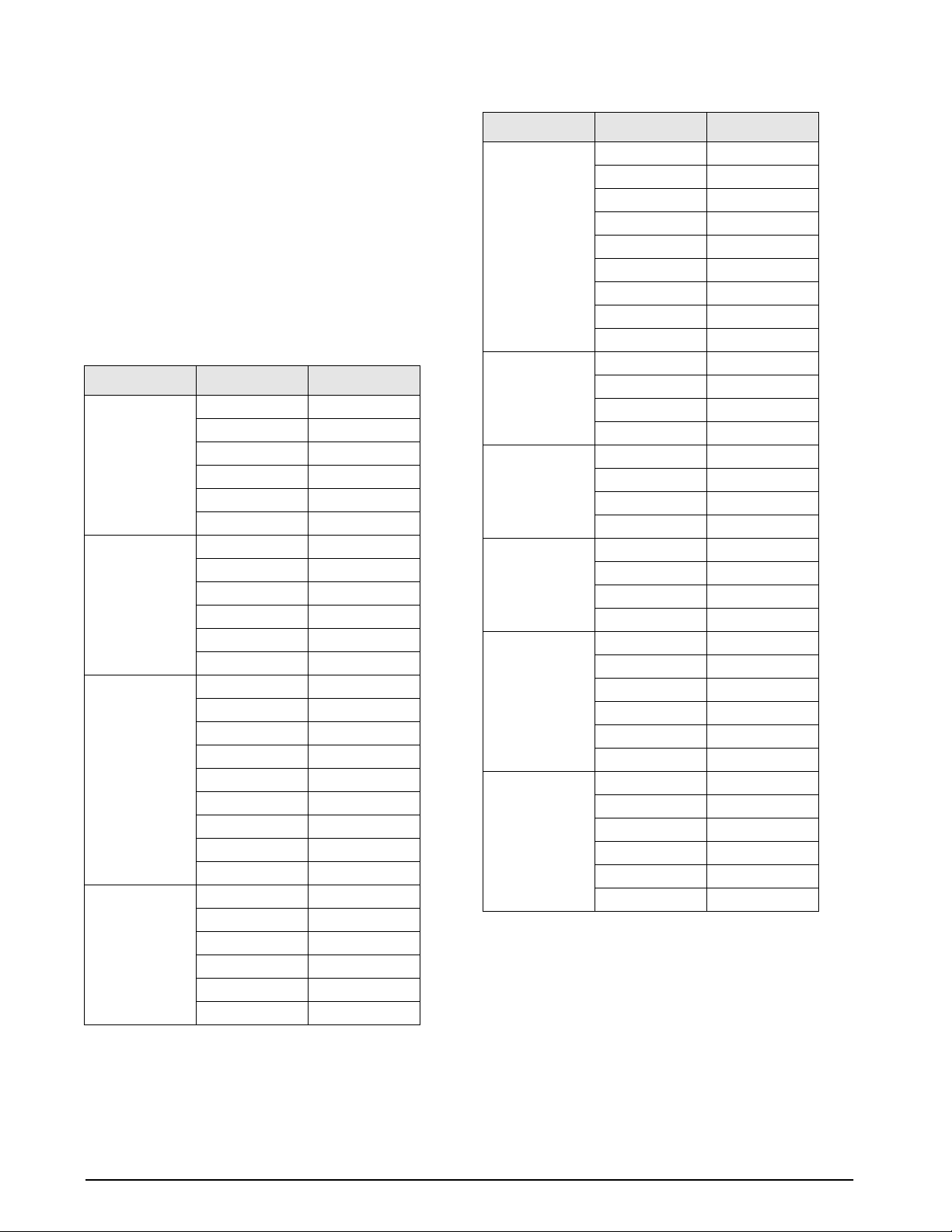
NOTE: Ensure that the secondary decimal point
position is set appropriately for the scale capacity in
the secondary units. If the converted value requires
more digits than are available, the indicator will
display an overflow message (
OVERFL).
For example, if the primary units are short tons,
secondary units are pounds, and the secondary
decimal point is set to 8888.888, the indicator will
overflow if 5 tons or more are applied to the scale.
With 5 tons applied, and a conversion factor of 2000,
the secondary units display needs five digits to the left
of the decimal point to display the 10000 lb secondary
units value.
Primary Unit x Multiplier Secondary Unit
grains 0.064799 grams
0.002286 ounces
0.000143 pounds
0.000065 kilograms
0.002083 troy ounces
0.000174 troy pounds
ounces 437.500 grains
28.3495 grams
0.06250 pounds
0.02835 kilograms
0.911458 troy ounces
0.075955 troy pounds
pounds 7000.00 grains
453.592 grams
16.0000 ounces
0.453592 kilograms
14.58333 troy ounces
1.215278 troy pounds
0.000500 short tons
0.000446 long tons
0.000453 metric tons
grams 15.4324 grains
0.035274 ounces
0.002205 pounds
0.001000 kilograms
0.032151 troy ounces
0.002679 troy pounds
Primary Unit x Multiplier Secondary Unit
kilograms 15432.4 grains
35.2740 ounces
1000.00 grams
2.20462 pounds
32.15075 troy ounces
2.679229 troy pounds
0.001102 short tons
0.000984 long tons
0.001000 metric tons
short tons 2000.00 pounds
907.185 kilograms
0.892857 long tons
0.907185 metric tons
metric tons 2204.62 pounds
1000.00 kilograms
1.10231 short tons
0.984207 long tons
long tons 2240.00 pounds
1016.05 kilograms
1.12000 short tons
1.01605 metric tons
troy ounces 480 grains
31.10348 grams
0.031103 kilograms
1.09714 ounces
0.068571 pounds
0.083333 troy pounds
troy pounds 5760 grains
373.2417 grams
0.373242 kilograms
13.16571 ounces
0.822857 pounds
12 troy ounces
Table 10-5. Conversion Factors (Continued)
Table 10-5. Conversion Factors
68 IQ plus 710 Installation Manual
Page 72
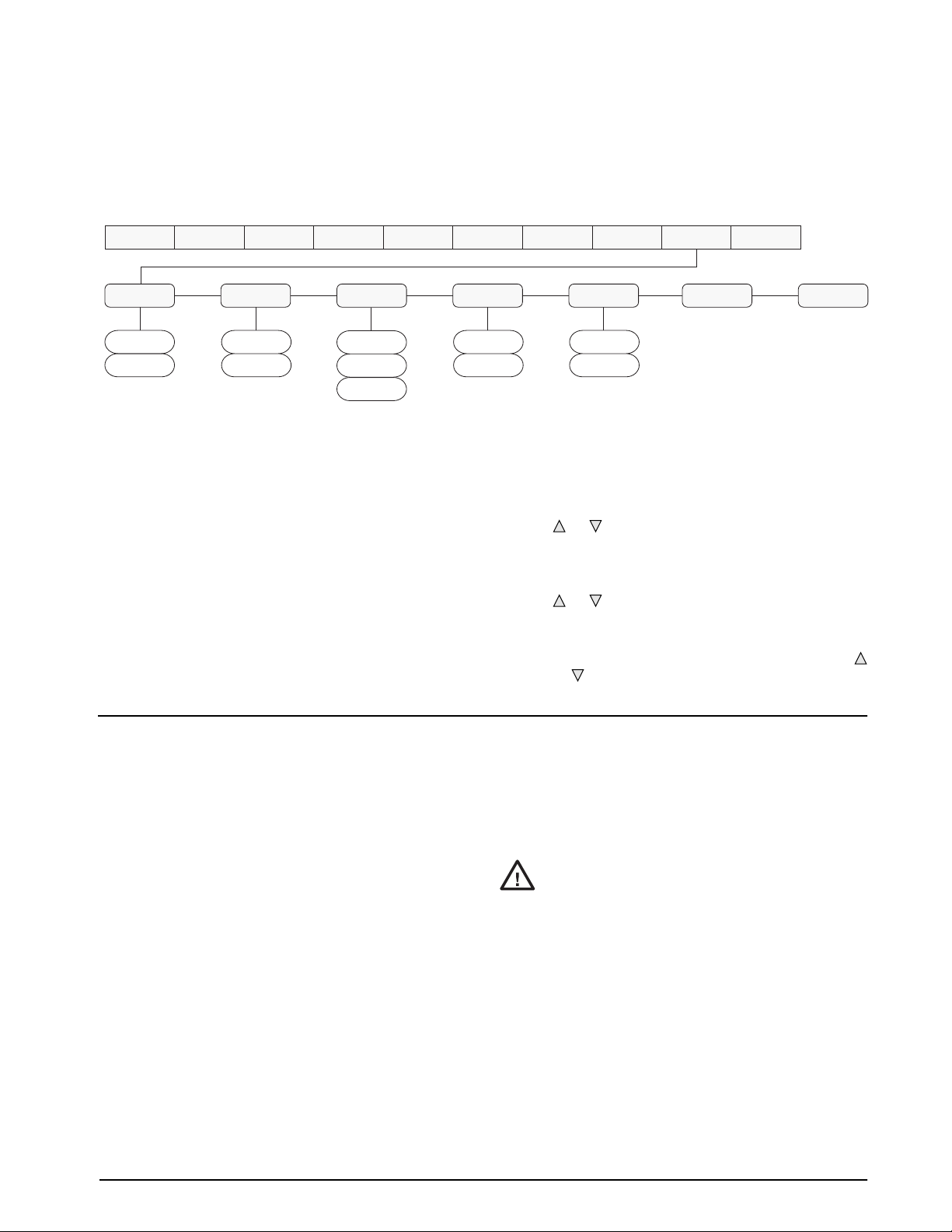
10.7 Analog Output Calibration
The following calibration procedure requires a
multimeter to measure voltage or current output from
the analog output module. If the option is not already
installed, see Section 2.4 on page 6.
NOTE: The analog output must be calibrated after the
indicator itself has been configured (Section 3.0) and
calibrated (Section 4.0).
SOURCE
GROSS
NET
OFFSET ERRACT
0%
20%
FULLSC
HOLD
ZEROSC
Figure 10-5. Analog Output Menu
1. Enter setup mode and go to the ALGOUT
menu (see Figure 10-5):
• Set OFFSET to 0% for 0–10 V output,
20% for 4–20 mA output
• Set MIN to lowest weight value to be
tracked by the analog output
• Set MAX to highest weight value to be
tracked by the analog output
2. Connect multimeter to connector J1 on the
analog output board:
• For voltage output, connect voltmeter
leads to pins 3 and 4
• For current output, connect ammeter
MIN
000000
number
XXXXXXX XXXXXXXALGOUTDIG INSETPNTSXXXXXXXPROGRM PFORMTSERIALCALIBRXXXXXXXCONFIG FORMAT
MAX TWZERO
10000
number
XXXXXXXVERS
TWSPAN
leads to pins 1 and 2
3. Adjust zero calibration: Scroll to the
TWZERO parameter. Check voltage or
current reading on multimeter. Press and hold
or to adjust the zero value up or down.
4. Adjust span calibration: Scroll to the
TWSPAN parameter. Check voltage or
current reading on multimeter. Press and hold
or to adjust the span value up or down.
5. Final zero calibration: Return to the
TWZERO parameter and verify that the zero
calibration has not drifted. Press and hold
or to re-adjust the zero value as required.
10.8 Test Mode
In addition to normal and setup modes, test mode
provides a number of diagnostic functions for the IQ
plus 710, including:
• Display raw A/D count
• Set digital outputs on and display digital input
states
• Reset configuration parameters to default
values
• Clear non-volatile (battery backed) storage
• Clear EEPROM
• Transmit test character (“U”) from serial port
• Display characters received by serial port
• Set analog output state to zero or full scale
• Set A/D offset and gain calibration
To enter test mode, press and hold the setup switch
until the front panel display shows the word
TEST. In
test mode, the front panel keys are mapped to the test
mode functions as shown in Figure 10-6 and
Table 10-6 on page 70.
A/D calibration functions, ADOFFS
Caution
after replacing A/D converter components. Improper A/D
calibration may render the indicator unusable.
The CLEAR EEPROM function erases both A/D and load
cell calibration data. The A/D converter and the scale
must be recalibrated after using this function.
and ADGAIN, must be used only by
qualified service personnel, and only
Appendix 69
Page 73

DI/O1= DI/O3= DI/O4=
DI/O2=
DI/O6=DI/O5= DI/O8=DI/O7=
XMT U ECHO R
EXIT
AOUT
=0
AOUT
=FS
EEPROM
Figure 10-6. Front Panel Key Functions in Test Mode
TEST Menu
Function Description
DI/O1 —DI/O8 Set digital output x high and display status of digital input x
Press and hold DI/Ox= key (see Figure 10-6) to show status of DIGINx (DIx=HI or DIx=LO).
AOUT=0 Set analog output to zero
Press and hold the F1 key to set analog output to its zero value.
AOUT=FS Set analog output to full scale
Press and hold the F2 key to set analog output to its full scale value.
XMT U Transmit “U”
Press and hold the 1 key to send ASCII “U” characters (decimal 85) from the serial port.
ECHO R Echo received characters
Press and hold the 2 key to view characters received at serial port.
NOTE: IQ plus 710 display shows lower-case characters as blanks.
A/D TEST Display A/D test
Press and hold the 7 key to display raw count from A/D converter.
CLEAR NVRAM Clear non-volatile storage
Press and hold the setup switch, then press the ENTER key to clear values stored in battery-backed SRAM,
including truck mode data, time, and date.
DEFAULT Default parameters
Press and hold the setup switch, then press the 0 key to reset configuration and calibration parameters to
factory default values. Load cells must be recalibrated before using the indicator (see Section 4.0 on
page 33).
CLEAR EEPROM Clear EEPROM
Read Caution! statement on page 69 before using this function.
Press and hold the setup switch, then press the
A/D OFFSET A/D offset calibration (–0.5 mv/V)
Read Caution! statement on page 69 before using this function. Press and hold the setup switch,
then press the 8 key to perform offset calibration.
A/D GAIN A/D gain calibration (+4.5 mv/V)
Read Caution! statement on page 69 before using this function. Press and hold the setup switch,
then press the 9 key to perform gain calibration.
EXIT Press the 3 key to exit test mode.
. (decimal_point) key to clear EEPROM.
A/D
TEST
CLEAR
A/D
OFFSET
DEFAULT
A/D
GAIN
CLEAR
NVRAM
70 IQ plus 710 Installation Manual
Table 10-6. Test Menu Functions
Page 74

10.9 Software Upgrade Instructions
Use the following procedure to replace the IQ plus
710 EPROM:
1. Disconnect indicator from power source.
2. Place indicator face-down on an antistatic
work mat. Remove screws that hold the
backplate to the enclosure body.
Warning
3. Loosen all in-use cord grips then lift the
backplate away from the enclosure and set it
aside.
Caution
4. For units using the Rev. 1 CPU board with
cable interface board, remove the four screws
that secure the interface board to its mounting
brackets. The interface board must be moved
to access the EPROM in the following step.
5. Locate the EPROM (see Figure 2-1 on page
5). Carefully remove old EPROM from
socket.
6. Remove new EPROM from packaging and
place on top of empty socket. Ensure EPROM
is correctly oriented (notch toward center of
CPU board) and all pins are aligned with
socket. Press down firmly to seat new
EPROM in the socket.
Disconnect power before removing
indicator backplate.
Use a wrist strap to ground yourself and
protect components from electrostatic
discharge (ESD) when working inside
the indicator enclosure.
7. For units using the Rev. 1 CPU board with
cable interface board, reinstall board using
screws removed in Step 4.
8. Position backplate over the enclosure and
reinstall the backplate screws. Use the torque
pattern shown in Figure 2-2 on page 7 to
prevent distorting the backplate gasket.
Torque backplate screws to 10 in-lb (1.13
N-m).
9. Ensure no excess cable is left inside the
enclosure and tighten cord grips.
10. Reconnect power to the indicator.
11. Remove the setup switch access screw on the
indicator backplate then set the indicator
upright.
12. Press and hold the setup switch until the front
panel display shows the word
TEST. Two test
mode procedures must be performed before
using the new EPROM:
• Clear non-volatile RAM (CLR NV)
• Restore defaults (DEFLT)
13. Press the
ENTER key and the setup switch at
the same time to clear non-volatile RAM.
(See Figure 10-6 on page 70 for test mode
keypad functions.)
14. Press the
0 (zero) key and the setup switch at
the same time to restore defaults. The
indicator automatically returns to normal
mode when done.
15. Recalibrate and reconfigure the indicator.
10.10 Software Revision History
The following list summarizes the principal software
changes made for Version 1.4:
Enhanced Display Resolution
Up to 100 000 grads can be specified on the GRADS
parameter (CONFIG menu) and on the GRADS EDP
command.
HDRFMT Ticket Header Print Format Added
Contents of the HDRFMT format can be inserted into
any other ticket format using the <AE> formatting
command. See Section 6.0 on page 45 for details.
Improved Digital Filtering
Digital filter sensitivity (DFSENS) and threshold
(DFTHRH) parameters on the CONFIG menu provide
improved digital filtering capability for the IQ plus
710. These values can also be configured using the
DFSENS and DFTHRH EDP commands. See
Section 10.5 on page 67 for detailed information
about using these parameters.
Single-Transaction Tare Weights and IDs
Version 1.44 supports temporary tare weights for
indicators configured to use stored IDs (TARE100
modes 3–6). This function allows one-time weighing
of trucks without adding the truck ID and tare weight
to the indicator database. See Section 7.1.3 on page 50
for more information.
EDP Commands
Several commands have been added to the Version
1.44 EDP command set:
• LOCKON/LOCKOFF commands to lock the
keypad in normal mode. These commands
provide the same function as the KYBDLK
command.
• DON/DOFF commands to set individual digital
outputs on or off. See Table 5-10 on page 41.
• BATSTART, BATRESET, BATPAUSE,
BATSTATUS batching control commands. See
Section 5.1.6 on page 43 for detailed
information about these commands.
Appendix 71
Page 75

10.11 Specifications
Power
Line Voltages 115 or 230 VAC
Frequency 50 or 60 Hz
Power Consumption 100 mA @ 115 VAC (11.5 W)
50 mA @ 230 VAC (11.5 W)
Fusing
115 VAC 2 x 160 mA TR5 subminiature fuses
Wickmann Time-Lag 19374 Series
UL Listed, CSA Certified and Approved
230 VAC 2 x 80 mA TR5 subminiature fuses
Wickmann Time-Lag 19372 Series
UL Recognized, Semko and VDE
Approved
Analog Specifications
Full Scale Input Signal Up to 45 mV
Excitation Voltage 10 ± 0.5 VDC,
8 x 350Ω or 16 x 700Ω load cells
Sense Amplifier Differential amplifier with
4- and 6-wire sensing
Analog Signal Input Range 0.6 mV/V – 4.5 mV/V
Analog Signal Sensitivity 0.3 µV/graduation minimum,
1.5 µV/grad recommended
Input Impedance 200 MΩ, typical
Noise (ref to input) 0.3 µV p-p with digital filter at 4
Internal Resolution 1 000 000 counts, approximate
Display Resolution 100 000 dd
Measurement Rate 60 measurements/sec, nominal
Input Sensitivity 50 nV per internal count
System Linearity Within 0.01% of full scale
Zero Stability 150 nV/°C, maximum
Span Stability 3.5 ppm/°C, maximum
Calibration Method Software, constants stored in
EEPROM
Common Mode
Voltage ± 4 V, referred to earth
Common Mode
Rejection 140 dB minimum @ 50 or 60 Hz
Normal Mode
Rejection 90 dB minimum @ 50 or 60 Hz
Input Overload ± 12 V continuous, static discharge
protected
RFI Protection Signal, excitation, and sense lines
protected by capacitor bypass
Analog Output Optional: fully isolated, voltage or current
output,14-bit resolution.
Voltage output: 0 –10 VDC
Load resistance:1kΩ minimum
Current output: 4–20 mA
External loop resistance: 500Ω maximum
Digital Specifications
Microcomputer Hitachi H8/3002 main processor @
9.8304 MHz
Digital Inputs 8 inputs, TTL or switch closure,
active-low
Digital Outputs 8 outputs, open collector with TTL
pullup, 250 mA sink, 40V withstand
Digital Filter Software selectable: 1–256, enhanced
Rattletrap
®
hybrid digital filtering
Serial Communications
EDP Port Full duplex RS-232 or RS-485
Printer Port RS-232 or active 20 mA current loop
Both Ports 19 200, 9600, 4800, 2400, 1200, 600, 300
bps; 7 or 8 data bits; even, odd, or no
parity; two stop bits on transmit, one stop
bit on receive
Operator Interface
Display Vacuum fluorescent display:
7-digit, 14-segment primary weight display;
Two 5x7 dot matrix digits for units, alpha/
numeric entry mode designators;
16-digit dot matrix display for additional
symbols, user prompts.
Keyboard 29-key membrane panel
Environmental
Operating Temperature–10 to +40°C (legal);
–10 to +50°C (industrial)
Storage Temperature –25 to +70°C
Humidity 0–95% relative humidity
Altitude 2000 m (6500 ft) maximum
Enclosure
Enclosure Dimensions (without tilt stand)
Sloped Enclosure: 9.5 in x 8.38 in x 4.95 in
241 mm x 213 mm x 126 mm
Flat Enclosure: 9.5 in x 8.38 in x 5.25 in
241 mm x 213 mm x 133 mm
Weight
Sloped Enclosure: 7.4 lb (3.3 Kg)
Flat Enclosure: 7.8 lb (3.5 Kg)
Rating/Material NEMA 4X/IP66, stainless steel
Certifications and Approvals
O
C
N
F
L
E
A
R
N
E
O
I
N
T
C
A
E
N
•
•
O
N
S
E
W
R
E
U
I
S
G
A
H
E
T
S
M
A
D
N
NTEP
CoC Number 98-081
Accuracy Class III/III L n
Measurement Canada
Approval AM-5253
Accuracy Class III n
max
III HDn
: 10 000
max
: 10 000
max
: 20 000
72 IQ plus 710 Installation Manual
Page 76

IQ plus 710 Limited Warranty
Rice Lake Weighing Systems (RLWS) warrants that all RLWS equipment and systems properly installed by a
Distributor or Original Equipment Manufacturer (OEM) will operate per written specifications as confirmed by
the Distributor/OEM and accepted by RLWS. All systems and components are warranted against defects in
materials and workmanship for two years.
RLWS warrants that the equipment sold hereunder will conform to the current written specifications authorized
by RLWS. RLWS warrants the equipment against faulty workmanship and defective materials. If any equipment
fails to conform to these warranties, RLWS will, at its option, repair or replace such goods returned within the
warranty period subject to the following conditions:
• Upon discovery by Buyer of such nonconformity, RLWS will be given prompt written notice with a
detailed explanation of the alleged deficiencies.
• Individual electronic components returned to RLWS for warranty purposes must be packaged to
prevent electrostatic discharge (ESD) damage in shipment. Packaging requirements are listed in a
publication, Protecting Your Components From Static Damage in Shipment, available from RLWS
Equipment Return Department.
• Examination of such equipment by RLWS confirms that the nonconformity actually exists, and was
not caused by accident, misuse, neglect, alteration, improper installation, improper repair or
improper testing; RLWS shall be the sole judge of all alleged non-conformities.
• Such equipment has not been modified, altered, or changed by any person other than RLWS or its
duly authorized repair agents.
• RLWS will have a reasonable time to repair or replace the defective equipment. Buyer is responsible
for shipping charges both ways.
• In no event will RLWS be responsible for travel time or on-location repairs, including assembly or
disassembly of equipment, nor will RLWS be liable for the cost of any repairs made by others.
HESE WARRANTIES EXCLUDE ALL OTHER WARRANTIES, EXPRESSED OR IMPLIED, INCLUDING WITHOUT
T
LIMITATION
RLWS NOR DISTRIBUTOR WILL, IN ANY EVENT, BE LIABLE FOR INCIDENTAL OR CONSEQUENTIAL DAMAGES.
RLWS
REPAIR
ALL
OTHER CLAIMS TO WARRANTY.
HOULD THE SELLER BE OTHER THAN RLWS, THE BUYER AGREES TO LOOK ONLY TO THE SELLER FOR
S
WARRANTY
O TERMS, CONDITIONS, UNDERSTANDING, OR AGREEMENTS PURPORTING TO MODIFY THE TERMS OF THIS
N
WARRANTY
OFFICER
WARRANTIES OF MERCHANTABILITY OR FITNESS FOR A PARTICULAR PURPOSE. NEITHER
AND BUYER AGREE THAT RLWSÕS SOLE AND EXCLUSIVE LIABILITY HEREUNDER IS LIMITED TO
OR REPLACEMENT OF SUCH GOODS. IN ACCEPTING THIS WARRANTY, THE BUYER WAIVES ANY AND
CLAIMS.
SHALL HAVE ANY LEGAL EFFECT UNLESS MADE IN WRITING AND SIGNED BY A CORPORATE
OF RLWS AND THE BUYER.
© 2000 Rice Lake Weighing Systems, Inc. Rice Lake, WI USA. All Rights Reserved.
RICE LAKE WEIGHING SYSTEMS • 230 WEST COLEMAN STREET • RICE LAKE, WISCONSIN 54868 • USA
Appendix 73
 Loading...