

Page 1
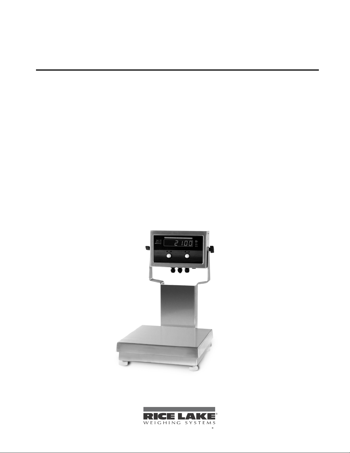
IQ plus® 2100
To be the best by ever y measure
Digital Bench Scale
Version 1.02
Installation Manual
53415
Page 2

Page 3

Contents
About This Manual................................................................................................................................... 1
1.0 Introduction.................................................................................................................................. 1
1.1 Operating Modes. . . . . . . . . . . . . . . . . . . . . . . . . . . . . . . . . . . . . . . . . . . . . . . . . . . . . . . . . . . . . . . . 1
1.2 Front Panel . . . . . . . . . . . . . . . . . . . . . . . . . . . . . . . . . . . . . . . . . . . . . . . . . . . . . . . . . . . . . . . . . . . . 2
1.3 LED Annunciators . . . . . . . . . . . . . . . . . . . . . . . . . . . . . . . . . . . . . . . . . . . . . . . . . . . . . . . . . . . . . . . 2
1.4 Indicator Operations . . . . . . . . . . . . . . . . . . . . . . . . . . . . . . . . . . . . . . . . . . . . . . . . . . . . . . . . . . . . . 2
2.0 Installation................................................................................................................................... 3
2.1 Unpacking and Assembly . . . . . . . . . . . . . . . . . . . . . . . . . . . . . . . . . . . . . . . . . . . . . . . . . . . . . . . . . 3
2.2 Factory Setup . . . . . . . . . . . . . . . . . . . . . . . . . . . . . . . . . . . . . . . . . . . . . . . . . . . . . . . . . . . . . . . . . . 3
3.0 Configuration................................................................................................................................ 4
3.1 Configuration Methods . . . . . . . . . . . . . . . . . . . . . . . . . . . . . . . . . . . . . . . . . . . . . . . . . . . . . . . . . . . 4
3.1.1 Revolution Configuration. . . . . . . . . . . . . . . . . . . . . . . . . . . . . . . . . . . . . . . . . . . . . . . . . . . . . . . . . . . . 4
3.1.2 EDP Command Configuration. . . . . . . . . . . . . . . . . . . . . . . . . . . . . . . . . . . . . . . . . . . . . . . . . . . . . . . . 4
3.1.3 Front Panel Configuration . . . . . . . . . . . . . . . . . . . . . . . . . . . . . . . . . . . . . . . . . . . . . . . . . . . . . . . . . . . 5
3.2 Menu Structures and Parameter Descriptions . . . . . . . . . . . . . . . . . . . . . . . . . . . . . . . . . . . . . . . . . . 8
3.2.1 Configuration Menu. . . . . . . . . . . . . . . . . . . . . . . . . . . . . . . . . . . . . . . . . . . . . . . . . . . . . . . . . . . . . . . . 8
3.2.2 Format Menu . . . . . . . . . . . . . . . . . . . . . . . . . . . . . . . . . . . . . . . . . . . . . . . . . . . . . . . . . . . . . . . . . . . . 9
3.2.3 Calibration Menu. . . . . . . . . . . . . . . . . . . . . . . . . . . . . . . . . . . . . . . . . . . . . . . . . . . . . . . . . . . . . . . . . 11
3.2.4 Serial Menu. . . . . . . . . . . . . . . . . . . . . . . . . . . . . . . . . . . . . . . . . . . . . . . . . . . . . . . . . . . . . . . . . . . . . 12
3.2.5 Digital Input Menu. . . . . . . . . . . . . . . . . . . . . . . . . . . . . . . . . . . . . . . . . . . . . . . . . . . . . . . . . . . . . . . . 13
3.2.6 Default Menu . . . . . . . . . . . . . . . . . . . . . . . . . . . . . . . . . . . . . . . . . . . . . . . . . . . . . . . . . . . . . . . . . . . 13
3.2.7 Version Menu . . . . . . . . . . . . . . . . . . . . . . . . . . . . . . . . . . . . . . . . . . . . . . . . . . . . . . . . . . . . . . . . . . . 13
4.0 Calibration.................................................................................................................................. 14
4.1 Front Panel Calibration. . . . . . . . . . . . . . . . . . . . . . . . . . . . . . . . . . . . . . . . . . . . . . . . . . . . . . . . . . . 14
4.2 EDP Command Calibration . . . . . . . . . . . . . . . . . . . . . . . . . . . . . . . . . . . . . . . . . . . . . . . . . . . . . . . 15
4.3 Revolution
5.0 EDP Commands.......................................................................................................................... 16
5.1 The EDP Command Set . . . . . . . . . . . . . . . . . . . . . . . . . . . . . . . . . . . . . . . . . . . . . . . . . . . . . . . . . 16
5.1.1 Key Press Commands . . . . . . . . . . . . . . . . . . . . . . . . . . . . . . . . . . . . . . . . . . . . . . . . . . . . . . . . . . . . 16
5.1.2 Reporting Commands. . . . . . . . . . . . . . . . . . . . . . . . . . . . . . . . . . . . . . . . . . . . . . . . . . . . . . . . . . . . . 16
5.1.3 The RESETCONFIGURATION Command . . . . . . . . . . . . . . . . . . . . . . . . . . . . . . . . . . . . . . . . . . . . . . 16
5.1.4 Parameter Setting Commands . . . . . . . . . . . . . . . . . . . . . . . . . . . . . . . . . . . . . . . . . . . . . . . . . . . . . . 16
5.1.5 Normal Mode Commands. . . . . . . . . . . . . . . . . . . . . . . . . . . . . . . . . . . . . . . . . . . . . . . . . . . . . . . . . . 18
5.2 Saving and Transferring Data. . . . . . . . . . . . . . . . . . . . . . . . . . . . . . . . . . . . . . . . . . . . . . . . . . . . . . 18
5.2.1 Saving Indicator Data to a Personal Computer . . . . . . . . . . . . . . . . . . . . . . . . . . . . . . . . . . . . . . . . . . 18
5.2.2 Downloading Configuration Data from PC to Indicator . . . . . . . . . . . . . . . . . . . . . . . . . . . . . . . . . . . . 18
6.0 Setup and Service Information.................................................................................................. 19
6.1 Enclosure Disassembly . . . . . . . . . . . . . . . . . . . . . . . . . . . . . . . . . . . . . . . . . . . . . . . . . . . . . . . . . . 19
6.2 Cable Connections . . . . . . . . . . . . . . . . . . . . . . . . . . . . . . . . . . . . . . . . . . . . . . . . . . . . . . . . . . . . . 19
6.2.1 Cable Grounding. . . . . . . . . . . . . . . . . . . . . . . . . . . . . . . . . . . . . . . . . . . . . . . . . . . . . . . . . . . . . . . . . 19
6.2.2 Load Cells. . . . . . . . . . . . . . . . . . . . . . . . . . . . . . . . . . . . . . . . . . . . . . . . . . . . . . . . . . . . . . . . . . . . . . 20
6.2.3 Setting the Load Cell Compensation Jumper . . . . . . . . . . . . . . . . . . . . . . . . . . . . . . . . . . . . . . . . . . . 20
6.2.4 Serial Communications. . . . . . . . . . . . . . . . . . . . . . . . . . . . . . . . . . . . . . . . . . . . . . . . . . . . . . . . . . . . 21
6.2.5 Digital Inputs. . . . . . . . . . . . . . . . . . . . . . . . . . . . . . . . . . . . . . . . . . . . . . . . . . . . . . . . . . . . . . . . . . . . 21
™
Calibration . . . . . . . . . . . . . . . . . . . . . . . . . . . . . . . . . . . . . . . . . . . . . . . . . . . . . . . . . . 15
Technical training seminars are available through Rice Lake Weighing Systems.
Course descriptions and dates can be viewed at www.rlws.com or obtained by
© 2003 Rice Lake Weighing Systems. All rights reserved. Printed in the United States of America.
calling 715-234-9171 and asking for the training department.
Specifications subject to change without notice.
Version 1.0, June 2003
Page 4

ii
6.3 Enclosure Reassembly. . . . . . . . . . . . . . . . . . . . . . . . . . . . . . . . . . . . . . . . . . . . . . . . . . . . . . . . . . . 21
6.4 Board Removal . . . . . . . . . . . . . . . . . . . . . . . . . . . . . . . . . . . . . . . . . . . . . . . . . . . . . . . . . . . . . . . . 21
6.5 IQ plus 210 Replacement Parts . . . . . . . . . . . . . . . . . . . . . . . . . . . . . . . . . . . . . . . . . . . . . . . . . . . . 22
6.6 Bench Scale Maintenance ................................................................................................................ 26
6.6.1 Load Cell Replacement. . . . . . . . . . . . . . . . . . . . . . . . . . . . . . . . . . . . . . . . . . . . . . . . . . . . . . . . . . . . 26
6.6.2 Bench Scale Adjustments. . . . . . . . . . . . . . . . . . . . . . . . . . . . . . . . . . . . . . . . . . . . . . . . . . . . . . . . . . 27
6.6.3 Clamshell Installation. . . . . . . . . . . . . . . . . . . . . . . . . . . . . . . . . . . . . . . . . . . . . . . . . . . . . . . . . . . . . . 27
6.7 RL2100 Replacement Parts. . . . . . . . . . . . . . . . . . . . . . . . . . . . . . . . . . . . . . . . . . . . . . . . . . . . . . . 28
7.0 Appendix.................................................................................................................................... 32
7.1 Error Messages . . . . . . . . . . . . . . . . . . . . . . . . . . . . . . . . . . . . . . . . . . . . . . . . . . . . . . . . . . . . . . . . 32
7.1.1 Displayed Error Messages. . . . . . . . . . . . . . . . . . . . . . . . . . . . . . . . . . . . . . . . . . . . . . . . . . . . . . . . . . 32
7.1.2 Using the XE EDP Command . . . . . . . . . . . . . . . . . . . . . . . . . . . . . . . . . . . . . . . . . . . . . . . . . . . . . . . 32
7.2 Status Messages. . . . . . . . . . . . . . . . . . . . . . . . . . . . . . . . . . . . . . . . . . . . . . . . . . . . . . . . . . . . . . . 33
7.2.1 Using the P EDP Command . . . . . . . . . . . . . . . . . . . . . . . . . . . . . . . . . . . . . . . . . . . . . . . . . . . . . . . . 33
7.2.2 Using the ZZ EDP Command . . . . . . . . . . . . . . . . . . . . . . . . . . . . . . . . . . . . . . . . . . . . . . . . . . . . . . . 33
7.3 Continuous Output (Stream) Format . . . . . . . . . . . . . . . . . . . . . . . . . . . . . . . . . . . . . . . . . . . . . . . . 33
7.4 Specifications . . . . . . . . . . . . . . . . . . . . . . . . . . . . . . . . . . . . . . . . . . . . . . . . . . . . . . . . . . . . . . . . . 34
7.4.1 IQ plus 210 Indicator. . . . . . . . . . . . . . . . . . . . . . . . . . . . . . . . . . . . . . . . . . . . . . . . . . . . . . . . . . . . . . 34
7.4.2 RL2100 Bench Scale . . . . . . . . . . . . . . . . . . . . . . . . . . . . . . . . . . . . . . . . . . . . . . . . . . . . . . . . . . . . . 34
IQ plus 2100 Limited Warranty.............................................................................................................. 35
IQ plus 2100 Installation Manual
Page 5

About This Manual
This manual is intended for use by service technicians
responsible for installing and servicing IQ plus
digital bench scales.
Configuration and calibration of the indicator can be
accomplished using the indicator front panel k eys, the
EDP command set, or Version 2.3 or later of the
™
Revolution
configuration utility. See Section 3.1 on
page 10 for information about configuration methods
®
2100
1.0 Introduction
Warning
Some procedures described in this
manual require work inside the indicator
enclosure. These procedures are to be
performed by qualified service personnel
only
.
Authorized distributors and their emplo yees
can view or download this manual from the
Rice Lake Weighing Systems distributor site
www.rlws.com
at
.
The IQ plus 2100 digital bench scale consists of an IQ
plus 210 digital weight indicator and an RL2100 bench
scale. The indicator can be mounted to the bench scale
using the 12-inch column or the attachment brack et, or
can be separately mounted on the tilt stand.
The IQ plus 210 is a single-channel digital weight
indicator housed in a NEMA 4X/IP66-rated stainless
steel enclosure. The indicator front panel consists of a
large (.8 in, 20 mm), six-digit, se ven-segment LED
display, seven LED annunciators, and tw o piezo
switches used to zero the scale and select the displayed
units. Features include:
• Drives up to four 350
• Supports 4- and 6-wire load cell connections
•Two configurable digital input
• Single serial port supports full duple x, RS-232
communications at up to 9600 bps
•Available in 115 VAC and 230 VAC versions
Ω load cells
The RL2100 bench scale is a vailable in the follo wing
configurations
• 5, 10, and 25 lb (2.5, 5, and 10 Kg) capacities with a
10" x 10" (25cm x 25cm) platform
• 50 and 100 lb (25 and 50 Kg) capacities with a 12" x
12" (30cm x 30cm) platform
The RL1042 anodized aluminum load cell is standard
in the RL2100 bench scale; the RL1380 stainless steel
load cell is a vailable as an option. A stainless steel
clamshell enclosure is also a vailable for load cell
protection.
1.1 Operating Modes
The IQ plus 210 has two modes of operation:
Normal (weighing) mode
Normal mode is the “production” mode of the
indicator. The indicator displays the gross weight,
and the LED annunciators described on page 2
indicate scale status and the type of weight v alue
displayed. Once configuration is complete and
legal seal is affi ed to the back of the indicator, this
is the only mode in which the IQ plus 210 can
operate.
Setup mode
Most of the procedures described in this manual
require the indicator to be in setup mode, including
configuration and calibration
To enter setup mode, remove the large fillister hea
screw from the enclosure backplate. Insert a
screwdriver or a similar tool into the access hole
and press the setup switch once. The indicator
display changes to show the word
CONFIG
.
Introduction
1
Page 6

2
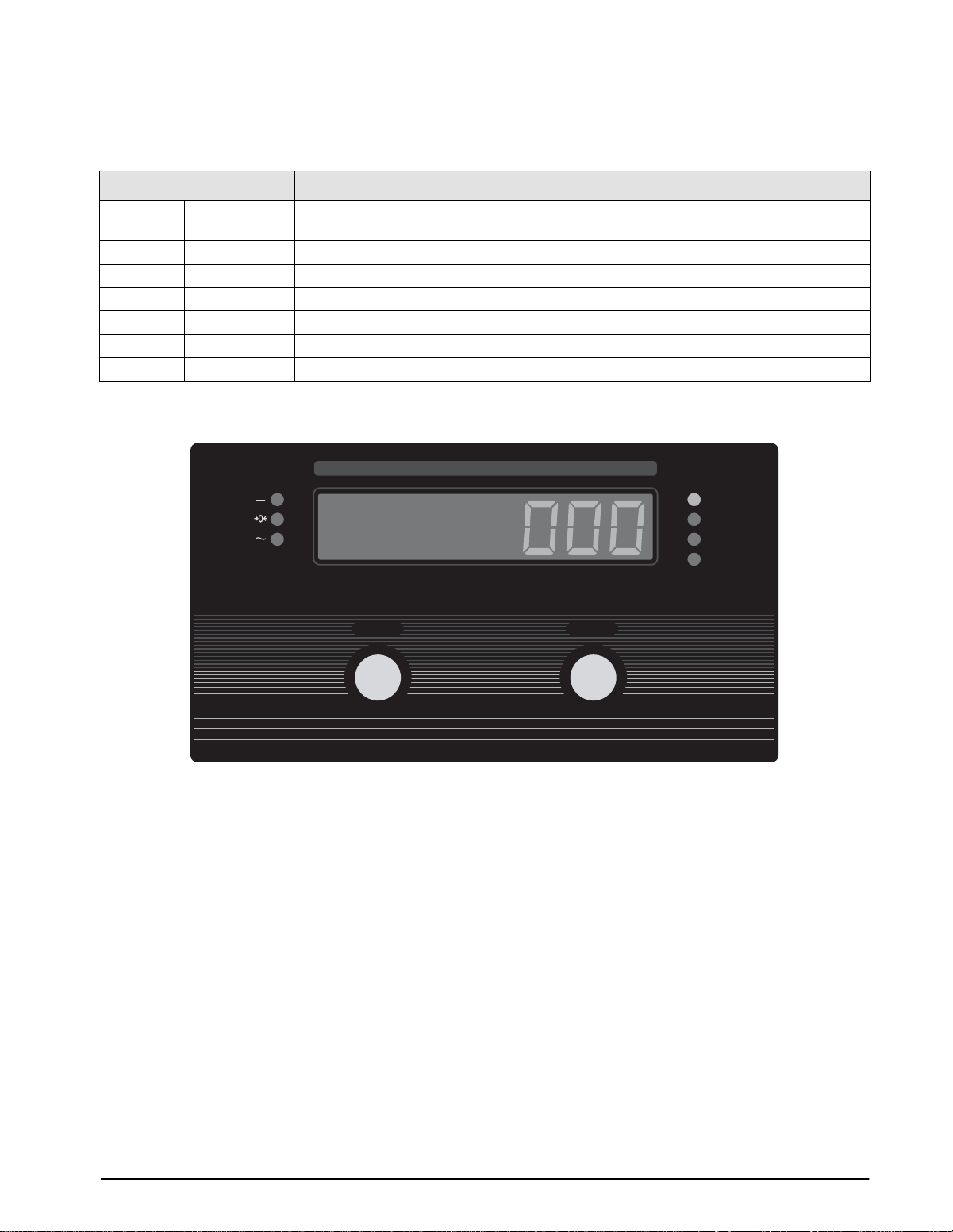
1.2 Front Panel
Figure 1-1 shows the IQ plus 210 LED annunciators, buttons, and normal mode key functions.
DIGITAL WEIGHT INDICATOR
Neg
Zero
Motion
ZERO
ZERO
Set scale weight to zero
Figure 1-1. IQ plus 210 Front Panel, Showing LED Annunciators and Normal Mode Key Functions
Change displayed units
UNITS
UNITS
kg
g
lb
oz
1.3 LED Annunciators
The IQ plus 210 display uses a set of se ven LED
annunciators to pro vide additional information about
the value being displayed:
Neg
•
•
•
•
annunciator lights to sho w that the displayed
value is negative.
Zero
: Weight is within 0.25 graduations of zero.
This annunciator lights when the scale is zeroed.
Motion
motion band. Zeroing and print operations can only
be done when the motion LED is off.
lb, kg, oz,
associated with the displayed v alue: lb=pounds,
kg=kilograms, oz=ounces, g=grams.
annunciators are both lit when the displayed weight
is in pounds and ounces.
: Scale in motion outside the specifie
and
g
annunciators indicate the units
lb
and
oz
1.4 Indicator Operations
Basic IQ plus 210 operations are summarized below.
Zero Scale
1. Remove material from the scale and w ait for
the
Motion
2. Press the
lights to indicate the scale is zeroed.
Change Display Units
Press the
UNITS
between primary and alternate units. The LED
annunciators on the right side of the display sho w the
current displayed units. If more than one alternate unit
is configured, the display ycles through the alternate
units before returning to primary units; if no alternate
units are configured, the display does not change whe
the button is pressed.
LED to go out.
ZERO
button. The
Zero
annunciator
button to change the displayed units
IQ plus 2100 Installation Manual
Page 7

2.0 Installation
The IQ plus 2100 digital bench scale is designed for easy
setup and installation. All models are preconfigured an
weight calibrated before shipment, with the load cell
connected to the indicator. For simple, standalone scale
applications, hardware installation consists of attaching
the indicator, mounting assembly, and bench scale, then
leveling the scale.
NOTE: The IQ plus 2100 is weight calibrated before
shipment from the factory, but recalibration at the
installation site is strongly recommended. Calibration by
a certified scale technician is required for Legal-for-Trade
applications.
2.1 Unpacking and Assembly
Immediately after unpacking, visually inspect the IQ
plus 2100 to ensure all components are included and
undamaged. The shipping carton should contain the
indicator, the bench scale, the indicator mount (tilt
stand, column, or attachment bracket), this manual, and
a parts kit. If an y parts were damaged in shipment,
notify Rice Lak e Weighing Systems and the shipper
immediately.
The parts kit contains the items listed below:
• Capacity label (PN 42350)
• One grounding clamp (PN 53075), e xternal
tooth lock washer, (PN 15133), and kep nut (PN
14626) for digital input or serial cable shield
grounding against the enclosure.
•Two wing knobs with n ylon washers for
attaching the indicator to the mounting
assembly, four rubber tilt stand feet (for tilt
stand option) or bench scale feet, jam nuts, lock
washers, and cap scre ws (for column and
attachment bracket options). See Section 6.7 on
page 28 for replacement part numbers.
To install, attach the mounting assembly to scale base,
then assemble the indicator to the mounting assembly .
Place the bench scale in the desired location then lift off
the scale platter and locate the b ubble level. Adjust the
corner feet until the scale is le vel and all feet are in
contact with the support surf ace. Tighten the jam nuts
against the scale to lock-in the level adjustment.
Plug power cord into power outlet to begin weighing.
The supply cord serves as the power
Caution
disconnect for the IQ plus 2100. The
power outlet supplying the indicator
must be installed near the unit and be
easily accessible.
2.2 Factory Setup
The IQ plus 2100 is preconfigured and weigh
calibrated at the factory before shipment. Table 2-1 lists
the default graduations and count-by configuration fo
each scale capacity.
Scale
Capacity
5 lb 0.001 lb 888.888 1D
10 lb 0.002 lb 888.888 2D
25 lb 0.005 lb 888.888 5D
50 lb 0.01 lb 8888.88 1D
100 lb 0.02 lb 8888.88 2D
2.5 Kg 0.0005 Kg 88.8888 5D
5 Kg 0.001 Kg 888.888 1D
10 Kg 0.002 Kg 888.888 2D
25 Kg 0.005 Kg 888.888 5D
50 Kg 0.01 Kg 8888.88 1D
NOTE: All capacities are preconfigured for 5000 graduations
(GRADS parameter on CONFIG menu set to 5000).
Table 2-1. Default Scale Configurations
Count by
If scale configuration must be changed, see Section 3.0
on page 4 for detailed configuration information. Se
Section 4.0 on page 14 for calibration instructions.
Configuration Parameters
DECPNT DSPDIV
Installation
3
Page 8
3.0 Configuration
10
To configure the IQ plus 210 indicator , the indicator
must be placed in setup mode. The setup switch is
accessed by remo ving the large fillister head scr w on
the enclosure backplate. Insert a scre wdriver into the
access hole and press the switch to enter setup mode.
When the indicator is placed in setup mode, the w ord
CONFIG
is shown on the display. The CONFIG menu is
the first of the main menus used to configure t
indicator. Detailed descriptions of these menus are
given in Section 3.2. When configuration is complete
press the setup switch ag ain to e xit setup mode, then
replace the setup switch access screw.
3.1 Configuration Methods
The IQ plus 210 indicator can be configured by usin
the front panel b uttons to navigate through a series of
configuration menus or by sending commands or
configuration data to the EDP port. Configuration usin
the menus is described in Section 3.1.3.
Configuration using the EDP port can be accomplished
using either the EDP command set described in
Section 5.0 or Version 2.3 or later of the Re volution
configuration utilit .
3.1.1 Revolution Configuration
The Revolution configuration utility pr vides the
preferred method for configuring the IQ plus 21
indicator. Revolution runs on a personal computer to set
configuration parameters for the indicator . When
Revolution configuration is complete, configurati
data is downloaded to the indicator.
™
To use Revolution, do the following:
1. Install Revolution on an IBM-compatible per-
®
sonal computer running Windows
3.11 or
Windows 95. Minimum system requirements
are 8MB of e xtended memory and at least
5MB of available hard disk space.
2. With both indicator and PC po wered off,
connect the PC serial port to the RS-232 pins
on the indicator EDP port.
3. Power up the PC and the indicator . Use the
setup switch to place the indicator in setup
mode.
4. Start the Revolution program.
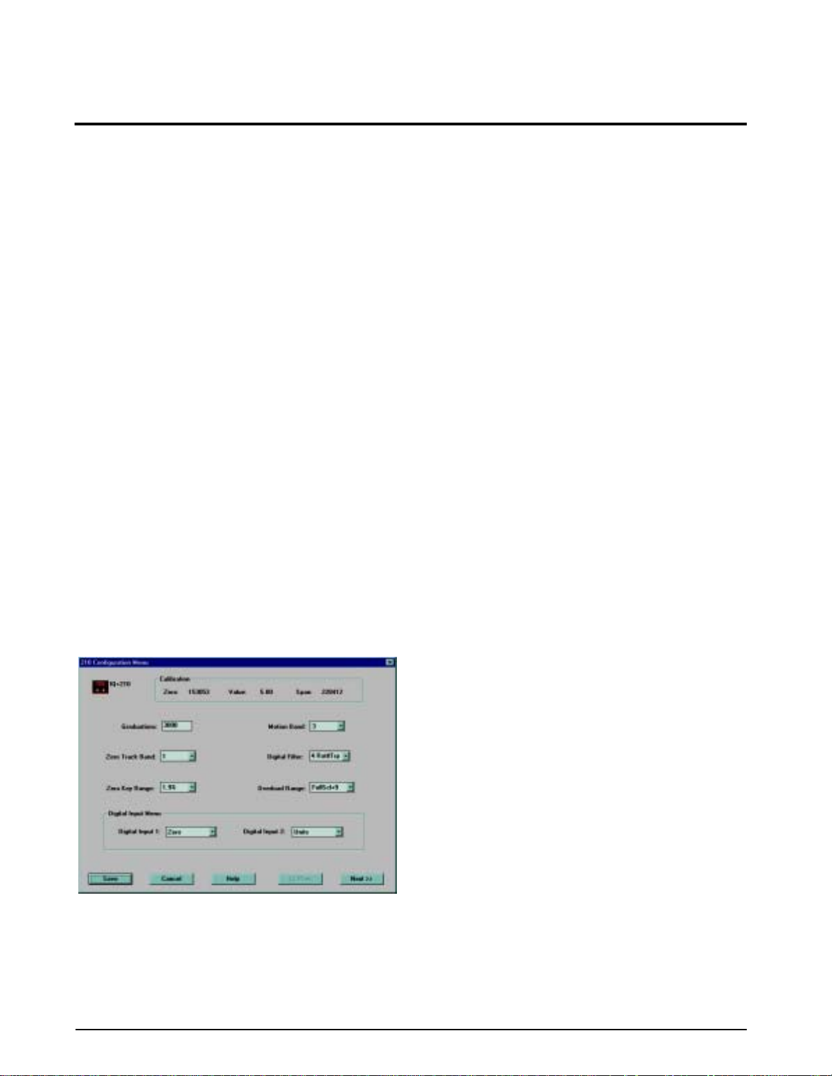
Figure 3-1 shows an example of one of the Re volution
configuration displays
Revolution provides online help for each of its
configuration displays. Parameter descriptions provided
in this manual for front panel configuration can also b
used when configuring the indicator using R volution:
the interface is different, but the parameters set are the
same.
3.1.2 EDP Command Configuration
The EDP command set can be used to configure the I
plus 210 indicator using a personal computer, terminal,
or remote k eyboard. Like Revolution, EDP command
configuration sends commands to the indicator serial
port; unlike Revolution, EDP commands can be sent
using any external device capable of sending ASCII
characters over a serial connection.
EDP commands duplicate the functions available using
the indicator front panel and pro vide some functions
not otherwise available. EDP commands can be used to
simulate pressing front panel b uttons, to configure th
indicator, or to dump lists of parameter settings. See
Section 5.0 on page 22 for more information about
using the EDP command set.
Figure 3-1. Sample Revolution Display
Revolution supports both uploading and do wnloading
of indicator configuration data. This capability allows
configuration data to be retrie ved from one indicator ,
edited, then downloaded to another.
IQ plus 2100 Installation Manual
Page 9
3.1.3 Front Panel Configuration
The IQ plus 210 indicator can be configured using a series of menus accessed through the indicator front pane
when the indicator is in setup mode. Table 3-1 summarizes the functions of each of the main menus.
Menu
Menu Function
CONFIG Configuration Configure grads, zero tracking, zero range, motion band, overload, and digital filtering
parameters.
FORMAT Format Set format of primary units, select alternate display units.
CALIBR Calibration Calibrate indicator. See Section 4.0 on page 20 for calibration procedures.
SERIAL Serial Configure serial port.
DIG IN Digital Input Assign digital input functions.
DEFLT Default Restore default configuration.
VERS Version Display installed software version number.
Table 3-1. IQ plus 210 Menu Summary
DIGITAL WEIGHT INDICATOR
Neg
Zero
Motion
ZERO
UNITS
kg
g
lb
oz
ZERO/ENTER
Move down in menu or
enter parameter value and
UNITS/RIGHT
Move right in menu /
next parameter value
return to menu level above
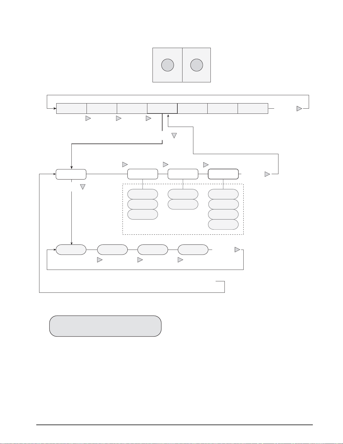
Figure 3-2. Front Panel Key Functions in Setup Mode
Configuration
11
Page 10
12
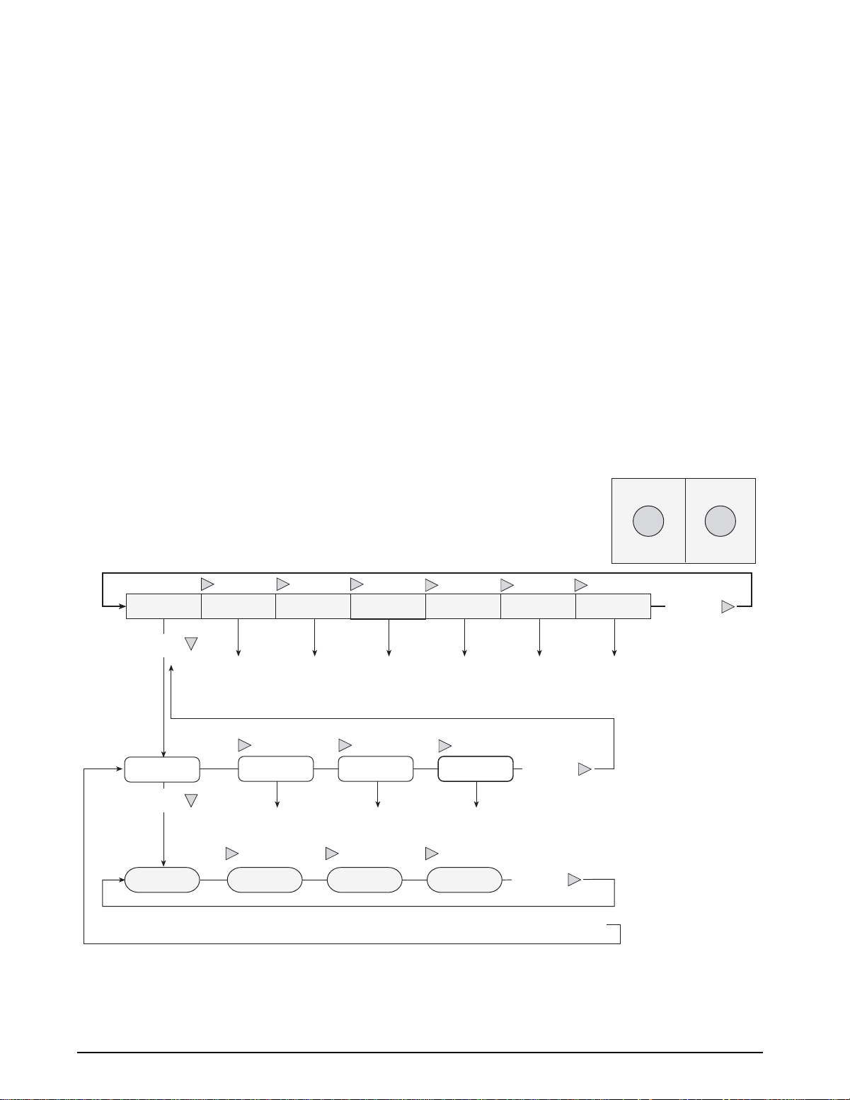
Front Panel Menu Navigation
The front panel buttons are used to navigate through the
menus in setup mode (see Figure 3-2). The
RIGHT
(
menu level; the
)
button scrolls right (horizontally) on the same
ZERO
ENTER
(
) button moves down
UNITS
(vertically) to dif ferent menu le vels and serv es as an
Enter key for selecting parameter v alues within the
menus.
Most of the configuration menus h ve three or four
levels. Figure 3-3 shows the general structure of the IQ
plus 210 configuration menus. Note the foll wing:
• On the first (main) menu l vel, press
through the menus. Pressing
menu wraps around to the CONFIG menu. Press
ENTER
to the first parameter for that menu
from any of the main menus to mo ve down
RIGHT
RIGHT
from the VERS
to scroll
Menu Navigation
General Structure
• On the middle (parameter) menu le vels, press
to scroll through the parameter prompts
RIGHT
for the menu.
displayed, pressing
above
. Press
When the last parameter is
RIGHT
returns to the level
ENTER
from any parameter prompt
to move down to the v alues prompts for that
parameter.
• On the bottom (parameter v alue) menu le vel,
RIGHT
press
parameter. Pressing
wraps around to first alue. Press
to scroll through the v alues for the
RIGHT
from the last v alue
ENTER
to
select the v alue and return to the parameter
prompt.
Figure 3-4 on page 13 sho ws an e xample of the
navigation used to select a parameter v alue under the
SERIAL menu.
To edit numerical v alues, use the
select the digit; use the
ENTER
RIGHT
button to
button to increment or
decrement the value of the flashing digit (see Figure3-5
on page 13). Once all digits ha ve been edited, press
ENTER
to save the value and return to the parameter
prompt.
ZERO
UNITS
ENTER
Parameter 1
ENTER
Press
RIGHT RIGHT RIGHT
Value 1
ENTER
Pressing
RIGHT RIGHT
RIGHT
at any parameter value to select the value and return to the parameter prompt
RIGHT
Parameter 2 Parameter 3 Parameter 4
RIGHT RIGHT
Value 2 Value 3 Value 4
RIGHT RIGHT RIGHT
SERIALCALIBRCONFIG FORMAT
at the last parameter prompt returns to the menu prompt
RIGHT
XXXXXXXXXXXXXX
RIGHT
RIGHT
VERSDEFLTDIG IN
(ENTER)
(RIGHT)
RIGHT
IQ plus 2100 Installation Manual
Figure 3-3. General Menu Structure
Page 11
Menu Navigation
Serial Menu Example
ZERO
(ENTER)
UNITS
(RIGHT)
RIGHT RIGHT RIGHT
RIGHT RIGHT
BAUD
ENTER
9600
RIGHT
1200
RIGHT RIGHT
SERIALCALIBRCONFIG FORMAT
ENTER
RIGHT
BITS TERMIN
8NONE
7EVEN
7ODD
CR/LF
CR
XXXXXXXXXXXXXX
When displaying last
parameter prompt, press
RIGHT
first-level menu prompt
48002400
to return to the
PRNFRQ
DEMAND
AUTO1
AUTO2
STREAM
RIGHT
VERSDEFLTDIG IN
RIGHT
Navigation functions same
as BAUD parameter
RIGHT
With any of the BAUD parameter values displayed, press
to select the value and return to the BAUD parameter prompt
Figure 3-4. Setup Mode Menu Navigation
0 0 0 0 0 0
To edit numeric values, press the
button to select the leftmost digit. Each digit flashes
when selected: Press
increment the value of the selected digit; press the
RIGHT
Once the last digit has been edited, press
again and the digit stops flashing. Press
to save the value entered and return to the menu level
above, or press
starting with the leftmost digit.
button to move right to the next digit.
RIGHT
Figure 3-5. Editing Procedure for Numeric Values
UNITS (RIGHT)
ZERO (ENTER)
RIGHT
ENTER
to edit the value again,
to
ENTER
Configuration 13
Page 12
3.2 Menu Structures and Parameter Descriptions
The following sections provide graphic representations of the IQ plus 210 menu structures. In the actual menu
structure, the values under each parameter are arranged horizontally. To save page space, menu choices are shown in
vertical columns. The factory default setting appears at the top of each column.
Most menu diagrams are accompanied by a table that describes all parameters and parameter values associated with
that menu. Default parameter values are shown in bold type.
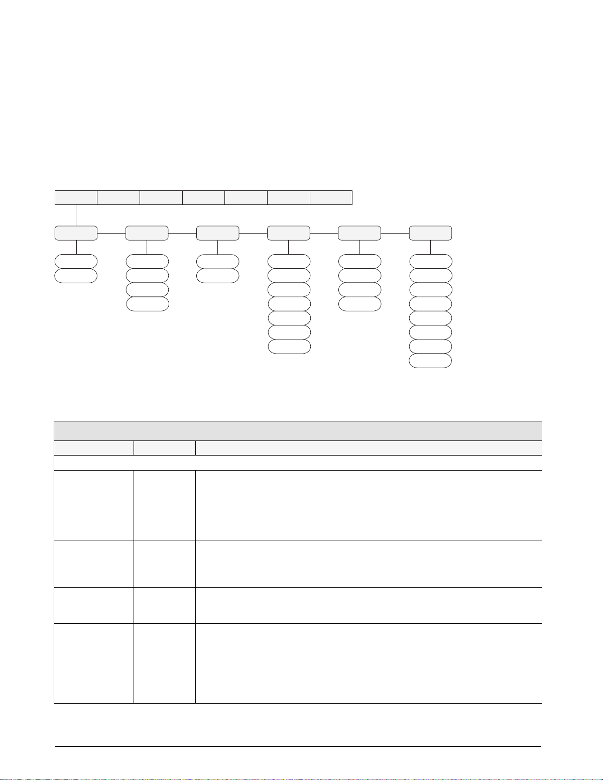
3.2.1 Configuration Menu
GRADS
5000
number
SERIALCALIBRCONFIG FORMAT
ZTRKBN ZRANGE
OFF
0.5D
1D
3D
100%
1.9%
XXXXXXXXXXXXXX
MOTBAN
1D
2D
3D
5D
10D
20D
OFF
VERSDEFLTDIG IN
OVRLOA
FS+2%
FS+1D
FS+9D
Figure 3-6. Configuration Menu
CONFIG Menu
Parameter Choices Description
Level 2 submenus
GRADS 5000
number
ZTRKBN OFF
0.5D
1D
3D
ZRANGE 100%
1.9%
MOTBAN 1D
2D
3D
5D
10D
20D
OFF
Graduations. Specifies the number of full scale graduations. The value entered must be in
the range 1–10 000 and should be consistent with legal requirements and environmental
limits on system resolution.
To calculate GRADS, use the formula, GRADS = Capacity / Display Divisions.
Display divisions for primary and secondary units are specified on the FORMAT menu.
Zero track band. Automatically zeroes the scale when within the range specified, as long
as the input is within the configured zero range (ZRANGE parameter). Selections are ±
display divisions. Maximum legal value varies depending on local regulations.
Zero range. Selects the range within which the scale can be zeroed. The 1.9% selection is
± 1.9% around the calibrated zero point, for a total range of 3.8%. Indicator must be at
standstill to zero the scale. Use 1.9% for legal-for-trade applications.
Motion band. Sets the level, in display divisions, at which scale motion is detected. If
motion is not detected for 1 second or more, the standstill symbol lights. Some
operations, including print, tare, and zero, require the scale to be at standstill. Maximum
legal value varies depending on local regulations.
If OFF is selected, ZTRKBN should also be set to OFF.
FS
FILTER
4
8
16
4RT
8RT
16RT
1
2
14 IQ plus 2100 Installation Manual
Table 3-2. Configuration Menu Parameters
Page 13
CONFIG Menu
Parameter Choices Description
OVRLOA FS+2%
FS+1D
Overload. Determines the point at which the display blanks and an out-of-range error
message is displayed. Maximum legal value varies depending on local regulations.
FS+9D
FS
FILTER 4
8
16
4RT
8RT
16RT
1
Digital filtering. Selects the digital filtering rate used to reduce the effects of mechanical
vibration from the immediate area of the scale.
Choices indicate the number of A/D conversions that are averaged to obtain the
displayed reading. A higher number gives a more accurate display by minimizing the
effect of a few noisy readings, but slows down the settling rate of the indicator. Values
with the RT suffix provide a raised threshold for filtering larger noise spikes.
2
Table 3-2. Configuration Menu Parameters (Continued)
3.2.2 Format Menu
SERIALCALIBRCONFIG FORMAT
PRIMAR ALTUNT
DSPDIVUNITS DECPNT
5D
1D
2D
ON
OFF
LB
KG
OZ
G
LB/OZ
If UNITS=LB/OZ,
DECPNT selections are:
888.888
8888.88
88888.8
888888
888880
8.88888
88.8888
88 88.8
888 88
Figure 3-7. Format Menu
XXXXXXXXXXXXXX
KG GOZLB
ON
OFF
VERSDEFLTDIG IN
LB/OZ
ON
OFF
ON
OFF
ON
OFF
Configuration 15
Page 14

FORMAT Menu
Parameter Choices Description
Level 2 submenus
PRIMAR UNITS
DECPNT
DSPDIV
ALTUNT LB
KG
OZ
G
LB/OZ
Level 3 submenus
Primary Units (PRIMAR Parameter)
DECPNT 888.888
8888.88
88888.8
888888
888880
8.88888
88.8888
or
88 88.8
888 88
DSPDIV 1D
2D
5D
UNITS LB
KG
OZ
G
LB/OZ
Alternate Units (ALTUNT Parameter)
LB
KG
OZ
G
LB/OZ
ON
OFF
Specifies the decimal position, display divisions, and units used for the primary units. See
Level 3 submenu parameter descriptions.
Specifies which alternate units can be displayed by pressing the UNITS. See Level 3
submenu parameter descriptions.
NOTE: The LB/OZ setting is not a Legal-for-Trade setting.
Decimal point location. Specifies the location of the decimal point or dummy zeroes in the
primary unit display. Value should be consistent with local legal requirements.
If LB/OZ is selected as the primary unit, DECPNT selections are 88 88.8 and 888 88.
Display divisions. Selects the minimum division size for the primary units displayed weight.
Specifies primary units for displayed and printed weight. Values are: LB=pound;
KG=kilogram; OZ=ounce; G=gram; LB/OZ=pounds and ounces.
Alternate units. Determines which units are displayed when the UNITS button is pressed.
The value for the primary unit (selected on the PRIMAR parameter) is always ON.
NOTE: The LB/OZ setting is not a Legal-for-Trade setting.
16 IQ plus 2100 Installation Manual
Table 3-3. Format Menu Parameters
Page 15

3.2.3 Calibration Menu
See Section 4.0 on page 20 for calibration procedures.
WZERO
*CAL*
Display and edit
zero calibration
A/D count value
WVAL
Display and edit
test weight value
SERIALCALIBRCONFIG FORMAT
WSPAN
*CAL*
Display and edit
span calibration
A/D count value
XXXXXXXXXXXXXX
REZERO
*
CAL*
Press Enter to
remove offset from
zero and span
calibrations
VERSDEFLTDIG IN
Figure 3-8. Calibration Menu
CALIBR Menu
Parameter Choices Description
Level 2 submenus
WZERO — Display and edit the zero calibration A/D count value.
WVAL — Display and edit the test weight value.
WSPAN — Display and edit the span calibration A/D count value.
REZERO — Press ENTER to remove an offset value from the zero and span calibrations.
Use this parameter only after WZERO and WSPAN have been set. See Section 4.1 on
page 20 for more information about using this parameter.
Table 3-4. Calibration Menu Parameters
Configuration 17
Page 16

3.2.4 Serial Menu
9600
1200
2400
4800
BITSBAUD
8NONE
7EVEN
7ODD
SERIALCALIBRCONFIG FORMAT
TERMIN
CR/LF
CR
ECHO
OFF
ON
XXXXXXXXXXXXXX
PRNFRQ
DEMAND
AUTO1
AUTO2
STREAM
Figure 3-9. Serial Menu
SERIAL Menu
Parameter Choices Description
BAUD 9600
Baud rate. Selects the transmission speed for the serial port.
1200
2400
4800
BITS 8NONE
Selects number of data bits and parity of data transmitted from the serial port.
7EVEN
7ODD
TERMIN CR/LF
Termination character. Selects termination character for data sent from the serial port.
CR
ECHO OFF
This command enables or disables echoing of the serial commands sent to the indicator.
ON
PRNFRQ DEMAND
AUTO1
AUTO2
STREAM
Print frequency. Specifies when the indicator sends data to the serial port:
DEMAND: When a PRINT digital input is activated or the KPRINT EDP command received.
AUTO1: Output enabled by scale in motion; transmitted when scale returns to standstill.
AUTO2: Output enabled by scale at center of zero; transmitted when a positive scale weight
is at standstill.
STREAM: Continuous output. See Section 6.3 on page 26 for output format.
Weight data is sent to the serial port in displayed units except when other units are specified
using one of the XGx EDP commands (see Section 5.1.5 on page 24).
If DEMAND, AUTO1, or AUTO2, is selected for this parameter, serial output is formatted as
follows:
wwwwwww uu GROSS
where wwwwww is a 7-digit weight field (leading zeroes suppressed, including decimal point and
minus sign, if required), uu is the units designator (lb, kg, oz, or G).
If pounds/ounces (LB/OZ) is specified as the primary units, the serial output is formatted as
shown below:
VERSDEFLTDIG IN
xxx lb yyyy oz GROSS
where xxx is the three-digit pounds weight (including minus sign, if required) followed by lb and
a space; and yyyy is the four-digit ounce weight (including decimal point) followed by oz.
18 IQ plus 2100 Installation Manual
Table 3-5. Serial Menu Parameters
Page 17

3.2.5 Digital Input Menu
SERIALCALIBRCONFIG FORMAT
DIGIN1
OFF
ZERO
UNITS
PRINT
XXXXXXXXXXXXXX
VERSDEFLTDIG IN
DIGIN2
OFF
ZERO
UNITS
PRINT
Figure 3-10. Digital Input Menu
DIG IN Menu
Parameter Choices Description
Level 2 submenus
DIGIN1
DIGIN2
OFF
ZERO
UNITS
PRINT
Specifies the function activated by digital inputs 1 and 2.
Table 3-6. Digital Input Menu Parameters
3.2.6 Default Menu
The DEFLT menu is used to reset indicator configuration to the de ault values. There are no parameters
associated with the DEFLT menu. From the DEFLT menu, press
parameter. Press
ENTER again to reset the indicator to the def ault configuration alues or press RIGHT (UNITS)
to cancel the indicator reset and return to the menu le vel above.
ENTER (ZERO) to move down to the RESET
NOTE: All load cell calibration settings are lost
when the RESET function is performed.
SERIALCALIBRCONFIG FORMAT
Figure 3-11. Default Menu
3.2.7 Version Menu
XXXXXXXXXXXXXX
RESET
VERSDEFLTDIG IN
The VERS menu is used to check the softw are version installed in the indicator . There are no parameters
associated with the VERS menu: when selected, the indicator displays the installed software version number.
SERIALCALIBRCONFIG FORMAT
Figure 3-12. Version Menu
XXXXXXXXXXXXXX
VERSDEFLTDIG IN
Software
version
Configuration 19
Page 18

4.0 Calibration
The IQ plus 210 can be calibrated using the front panel, EDP commands, or the Re volution™ configuration utility.
Each method consists of the following steps:
• Zero calibration
• Entering the test weight value
• Span calibration
• Optional rezero calibration for test weights using hooks or chains.
The following sections describe the calibration procedure for each of the calibration methods.
SERIALCALIBRCONFIG FORMAT
WZERO
*CAL*
Display and edit
zero calibration
A/D count value
WVAL
Display and edit
test weight value
WSPAN
*CAL*
Display and edit
span calibration
A/D count value
Figure 4-1. Calibration (CALIBR) Menu
4.1 Front Panel Calibration
To calibrate the indicator using the front panel, do the
following:
1. Place the indicator in setup mode (display
reads
CONFIG) and remo ve all weight from
the scale platform. If your test weights require
hooks or chains, place the hooks or chains on
the scale for zero calibration.
2. Press the
display reads CALIBR (see Figure 4-1). Press
ENTER (ZERO) to go to zero calibration
WZERO).
(
3. With
calibrate zero. The indicator displays °CAL°
while calibration is in progress. When
complete, the A/D count for the zero
calibration is displayed. Press ENTER again to
save the zero calibration value and return to the
WZERO prompt or use the procedure sho wn in
Figure 4-2 to edit the v alue. When done, press
RIGHT to go to the WVAL prompt.
4. With
the test weight value. If the value is equal to the
test weight you are using, press ENTER again
to save the v alue and return to the WVAL
prompt; if the v alue is incorrect, use the
procedure shown in Figure 4-2 to edit the
value. When done, press RIGHT to go to the
WSPAN prompt.
RIGHT (UNITS) button until the
WZERO displayed, press ENTER to
WVAL displayed, press ENTER to show
XXXXXXXXXXXXXX
REZERO
*CAL*
Press Enter to
remove offset from
zero and span
calibrations
NOTE: When calibrating the indicator with
LB/OZ as the primary unit, enter the WVAL value
in ounces. For example, to calibrate a 5 lb scale
using LB/OZ, enter 80 (5 lb x 16 oz/lb) as the
WVAL value.
VERSDEFLTDIG IN
5. With WSPAN displayed, place test weights on
the scale then press ENTER to calibrate span.
The indicator displays °CAL° while calibration
is in progress. When complete, the A/D count
for the span calibration is displayed. Press
ENTER again to save the span calibration value
and return to the WSPAN prompt or use the
procedure shown in Figure 4-2 to edit the
value. When done, press RIGHT to go to the
REZERO prompt.
0 0 0 0 0 0
To edit numeric values, press the
button to select the leftmost digit. Each digit flashes
when selected: Press
increment the value of the selected digit; press the
RIGHT
Once the last digit has been edited, press
again and the digit stops flashing. Press
to save the value entered and return to the menu level
above, or press
starting with the leftmost digit.
button to move right to the next digit.
RIGHT
UNITS (RIGHT)
ZERO (ENTER)
RIGHT
ENTER
to edit the value again,
to
20 IQ plus 2100 Installation Manual
Figure 4-2. Editing Procedure for Numeric Values
Page 19

6. The rezero function is used to remo ve a
calibration offset when hooks or chains are
used to hang the test weights.
• If no other apparatus was used to hang the
test weights during calibration, remove the
test weights and press
RIGHT to return to
the CALIBR menu.
• If hooks or chains were used during
calibration, remove these and the test
weights from the scale. With all weight
removed, press
ENTER to rezero the scale.
This function adjusts the zero and span
calibration values. The indicator displays
°CAL° while the zero and span calibrations
are adjusted. When complete, the adjusted
A/D count for the zero calibration is
displayed. Press ENTER again to save the
rezero value and return to the
REZERO
prompt or use the procedure shown in
Figure 4-2 to edit the value. When done,
press RIGHT to return to the CALIBR
menu.
7. Press the setup switch to exit setup mode.
4.2 EDP Command Calibration
To calibrate the indicator using EDP commands, the
indicator EDP port must be connected to a terminal or
personal computer. (See Section 2.3.3 on page 5 for
EDP port pin assignments; see Section 5.0 on page 22
for more information about using EDP commands.)
Once the indicator is connected to the sending de vice,
do the following:
1. Place the indicator in setup mode (display
CONFIG) and remo ve all weight from
reads
the scale platform. If your test weights require
hooks or chains, place the hooks or chains on
the scale for zero calibration.
2. Send the WZERO EDP command to calibrate
zero. The indicator displays
calibration is in progress.
3. Send the WVAL command to enter the test
weight value in the following format:
WVAL=nnnnnn<CR>
4. Place test weights on scale equal to the
specified WVAL.
5. Send the WSPAN EDP command to calibrate
span. The indicator displays
calibration is in progress.
6. To remove an of fset value, clear all weight
from the scale, including hooks or chains used
to hang test weights, then send the REZER O
EDP command. The indicator displays
while the zero and span calibrations are
adjusted.
7. Send the KEXIT EDP command to e xit setup
mode.
°CAL° while
°CAL° while
°CAL°
4.3 Revolution™ Calibration
To calibrate the indicator using Re volution, the
indicator must be in setup mode with the EDP port
connected to a PC running the Revolution configuratio
utility. Use the follo wing procedure to calibrate the
indicator:
1. Select
main menu.
2. On the Weight Calibration display , select the
indicator model (
port then click OK.
3. Revolution uploads calibration data from the
indicator then presents the information in a
display like that shown in Figure 4-3.
4. Enter the
span calibration then click
5. The Zero Calibration dialog box prompts you
to remove all weight from the scale. Clear the
scale and click
NOTE: If your test weights require hooks or
chains, place the hooks or chains on the scale
for zero calibration.
6. When zero calibration is complete, the Span
Calibration dialog box prompts you to place
test weights on the scale for span calibration.
Place tests weights on the scale then click OK.
7. The Rezero dialog box prompts you to remo ve
all weight, from the scale (including hooks or
chains). Remove the weights then click
8. When calibration is complete, the
Settings fields of the Weight Calibration
display are filled in. Click Exit to save the new
values and return to the Revolution main menu;
to restore the previous calibration values, click
Restore Settings.
Figure 4-3. Revolution Calibration Display
Calibrate Indicator from the Revolution
IQ+210) and communications
Value of Test Weight to be used for
OK.
OK to begin zero calibration.
OK.
New
Calibration 21
Page 20

5.0 EDP Commands
The IQ plus 210 indicator can be controlled by a
personal computer or remote keyboard connected to the
indicator serial port. Control is pro vided by a set of
EDP commands that can simulate front panel k ey press
functions, display and change setup parameters, and
perform reporting functions. The EDP port provides the
capability to print configuration data or to s ve that data
to an attached personal computer . This section
describes the EDP command set and procedures for
saving and transferring data using the serial port.
5.1 The EDP Command Set
The EDP command set can be divided into fi e groups:
key press commands, reporting commands, the
RESETCONFIGURATION special function
command, parameter setting commands, and transmit
weight data commands.
When the indicator processes an EDP command, it
responds with the message
verifies that the command w as received and has been
executed. If the command is unrecognized or cannot be
executed, the indicator responds with
The following sections list the commands and
command syntax used for each of these groups.
5.1.1 Key Press Commands
Key press EDP commands (see T able 5-1) simulate
pressing the buttons on the front panel of the indicator.
Command Function
KZERO Press the ZERO button
KUNITS Press the UNITS button
KPRIM Display primary units
KPRINT Send demand data to serial port
KRIGHTARROW In setup mode, move right in the menu
(press the UNITS button)
KENTER In setup mode, press the ENTER
(ZERO) button
KEXIT In setup mode only, exit setup mode
Table 5-1. EDP Key Press Commands
OK. The OK response
??.
5.1.2 Reporting Commands
Reporting commands (see T able 5-2) send specifi
information to the EDP port. These commands can be
used in both setup mode and normal mode.
Command Function
DUMPALL List all parameter values
VERSION
PWrite current displayed weight. See
ZZ Write current weight and annunciator
RS Reset the indicator
SWrite one frame of stream format
5.1.3 The RESETCONFIGURATION Command
Write IQ plus 210 software version
Section 6.2 on page 26 for more
information.
status. See Section 6.2 on page 26 for
more information.
Table 5-2. EDP Reporting Commands
The RESETCONFIGURATION command can be used
to restore all configuration parameters to their de ault
values.
This command is equi valent to using the RESET
function on the DEFLT menu.
NOTE: All load cell calibration settings are lost when the
RESETCONFIGURATION command is run.
5.1.4 Parameter Setting Commands
Parameter setting commands allo w you to display or
change the current value for a particular configuratio
parameter (Tables 5-3 through 5-8).
Current configuration parameter settings can b
displayed in either setup mode or normal mode using
the following syntax:
command<ENTER>
Most parameter values only can be changed in setup
mode. Use the follo wing command syntax when
changing parameter values:
command=value<ENTER>
where value is a number or a parameter v alue. Use no
spaces before or after the equal (=) sign. If you type an
incorrect command or v alue, the display reads
??.
Changes to the parameters are saved as they are entered
but typically do not tak e effect until you e xit setup
mode.
For example, to set the motion band parameter to 5,
type the following:
MOTBAND=5D<ENTER>
22 IQ plus 2100 Installation Manual
Page 21

Command Description Values
GRADS Graduations 1–10 000
ZTRKBND Zero track band OFF, 0.5D, 1D, 3D
ZRANGE Zero range 1.9%, 100%
MOTBAND Motion band 1D, 2D, 3D, 5D, 10D, 20D, OFF
OVRLOAD Overload FS+2%, FS+1D, FS+9D, FS
FILTER Digital filtering 1, 2, 4, 8, 16, 4RT, 8RT, 16RT
Table 5-3. CONFIG EDP Commands
Command Description Values
PRI.DECPNT Primary units decimal position 8.88888, 88.8888, 888.888, 8888.88, 88888.8, 888888, 888880
(88 88.8 or 888 88 in LB/OZ display mode)
PRI.DSPDIV Primary units display divisions 1D, 2D, 5D
PRI.UNITS Primary units LB, KG, OZ, G, LB/OZ
ALT.LB
ALT.KG
ALT.OZ
ALT.G
ALT.LBOZ
Enable alternate units ON, OFF
Table 5-4. FORMAT EDP Commands
Command Description Values
WZERO Zero calibration —
WVAL Test weight value test_weight_value
WSPAN Span calibration —
REZERO Rezero —
LC.CD Set deadload count value
LC.CW Set span count value
Table 5-5. CALIBR EDP Commands
Command Description Values
EDP.BAUD Serial port baud rate 1200, 2400, 4800, 9600
EDP.BITS Serial port data bits/parity 8NONE, 7EVEN, 7ODD
EDP.TERMIN Serial port termination character CR/LF, CR
EDP.ECHO Serial port echo command OFF, ON
PRNFREQ Print frequency DEMAND, AUTO1, AUTO2, STREAM
Table 5-6. SERIAL EDP Commands
Command Description Values
DIGIN1
DIGIN2
Digital input function OFF, ZERO, UNITS, PRINT
Table 5-7. DIG IN EDP Commands
EDP Commands 23
Page 22

5.1.5 Normal Mode Commands
The serial transmit weight data commands (see Table 5-8) transmit data to the serial port on demand. The transmit
weight data commands are valid only in normal operating mode.
Command Description Response Format
SX Start serial streaming OK or ??
EX Stop serial streaming OK or ??
RS Reset system —
XG Transmit gross weight in displayed units nnnnnn UU
where nnnnnn is the weight value, UU is the units.XGL Transmit gross weight in pounds
XGK Transmit gross weight in kilograms
XGO Transmit gross weight in ounces
XGG Transmit gross weight in grams
XGC Transmit gross weight in pounds and ounces
XE Query system error conditions nnnnn nnnnn
See Section 6.1.2 on page 25 for detailed information about
the XE command response format.
Table 5-8. Normal Mode EDP Commands
5.2 Saving and Transferring Data
Connecting a personal computer to the IQ plus 210
EDP port allo ws you to sa ve indicator configuratio
data to the PC or to do wnload configuration data fro
the PC to an indicator. The following sections describe
the procedures for these save and transfer operations.
5.2.1 Saving Indicator Data to a Personal Computer
Configuration data can be saved to a personal computer
connected to the EDP port. The PC must be running a
communications program such as PROCOMMPLUS
See Section 2.3.3 on page 5 for information about serial
communications wiring and EDP port pin assignments.
When configuring the indicato , ensure that the v alues
set for the BAUD and BITS parameters on the SERIAL
menu match the baud rate, bits, and parity settings
configured for the serial port on the PC
To save all configuration data, send the DUM ALL
EDP command to the indicator . The IQ plus 210
responds by sending all configuration parameters to th
PC as ASCII-formatted text.
5.2.2 Downloading Configuration Data from PC to
Indicator
Configuration data saved on a PC or flop y disk can be
downloaded from the PC to an indicator . This
procedure is useful when a number of indicators with
similar configurations are set up or when an indicator i
replaced.
To download configuration data, connect the PC to th
EDP port as described in Section 5.2.1. Place the
®
.
indicator in setup mode and use the PC
communications software to send the sa ved
configuration data to the indicator . When transfer is
complete, calibrate the indicator as described in
Section 4.0 on page 20.
NOTES:
• Calibration settings are included in the
configuration data do wnloaded to the indicator .
If the receiving indicator is a direct replacement
for another IQ plus 210 and the attached scale is
not changed, recalibration is not required.
• When downloading configurations that includ
changed serial communications settings, edit the
data file to place the serial communication
changes at the end of the file. Communicatio
between the PC and indicator will be lost once
the indicator recei ves settings for baud rate
(BAUD parameter) or data bits and parity (BITS
parameter) that do not match those configure
for the PC.
24 IQ plus 2100 Installation Manual
Page 23

2.0 Setup and Service Information
Cord grip
Insulated cable
Foil (silver side out)
Grounding clamp
Shield wire (cut)
Length of foil before folding
back on cable insulation
Cut insulation here
for foil-shielded cables
Braid
Cut insulation here
for braided cables
NOTE: Install lockwashers
first, against enclosure,
under grounding clamp
This section describes setup and service procedures for the IQ plus 2100 digital bench scale, including installation
and maintenance information, replacement parts lists, and assembly dra wings. See Sections 2.1 through 2.5 for IQ
plus 210 indicator information; see Sections 6.6 and 6.7 for bench scale information.
2.1 Enclosure Disassembly
The indicator enclosure must be opened to connect
cables after replacing the load cell, or when connecting
serial communications cables or digital inputs to the
scale.
The IQ plus 210 has no on/off switch.
Warning
Caution
• Use a wrist strap to ground yourself and protect
components from electrostatic discharge (ESD)
when working inside the indicator enclosure.
• This unit uses double pole/neutral fusing which
could create an electric shock hazard. Procedures
requiring work inside the indicator must be
performed by qualified service personnel only.
• The supply cord serves as the power disconnect for
the IQ plus 2100. The power outlet supplying the
indicator must be installed near the unit and be
easily accessible
Ensure power to the indicator is disconnected, then
remove the scre ws that hold the backplate to the
enclosure body, then lift the backplate a way from the
enclosure and set it aside.
2.2 Cable Connections
The IQ plus 210 pro vides three cord grips for cabling
into the indicator: tw o for the power cord and load cell
cabling, the third for communications and digital input
cables. The free cord grip comes with a plug installed to
prevent moisture from entering the enclosure. If your
application requires serial communication or digital
input cabling, remo ve the plug and install cables as
described in Sections 2.2.4 and 2.2.5 on page 5.
Before opening the unit, ensure the
power cord is disconnected from the
power outlet.
• Route cables through cord grips and grounding
clamps to determine cable lengths required to
reach cable connectors. Mark cables to remo ve
insulation and shield as described below:
•For cables with foil shielding, strip insulation
and foil from the cable half an inch (15 mm)
past the grounding clamp (see Figure 2-1). Fold
the foil shield back on the cable where the cable
passes through the clamp. Ensure silv er
(conductive) side of foil is turned outw ard for
contact with the grounding clamp.
•For cables with braided shielding, strip cable
insulation and braided shield from a point just
past the grounding clamp. Strip another half
inch (15 mm) of insulation only to expose the
braid where the cable passes through the clamp
(see Figure 2-1).
IMPORTANT! For load cell cables, strip the
•
yellow shield wire 3/4" past the grounding
clamp. Fold wire back and secure between the
cable and clamp. Shield wire function is
provided by contact between the cable shield
and the grounding clamp.
• Route stripped cables through cord grips and
clamps. Ensure shields contact grounding clamps
as shown in Figure 2-1. Tighten grounding clamp
nuts.
• Finish installation using cable mounts and ties to
secure cables inside of indicator enclosure.
2.2.1 Cable Grounding
Except for the power cord, all cables routed through the
cord grips should be grounded ag ainst the indicator
enclosure. Do the following to ground shielded cables:
• Use the lockw ashers, clamps, and k ep nuts
provided in the parts kit to install grounding
clamps on the studs adjacent to the cord grips.
Install grounding clamps only for cord grips that
will be used; do not tighten nuts.
Figur e 2-1. Grounding Clamp Attachment for F oil-Shielded
and Braided Cabling
Setup and Service Information 3
Page 24

To setup switch
Microprocessor
J1
GND
RESET
A/D Converter
GND
11
J3
J2
DIGIN 2 DIGIN 1
Figure 2-2. IQ plus 210 CPU and Power Supply Board
UNITS
Button
J4
DIGITAL
+5V
TEST
VR1 VR2
JP2
JP1
LOAD CELL CONNECTOR
1 23456
–SIG
+SIG
+SENSE
ANALOG
+5V
TEST
+EXC
–SENSE
J5
–EXC
GND
TxD
1
GND
2
RxD
3
J7
TP1
+
BR1
JP1
ON
OFF
Load cell
compensation
jumper
VR3
–
TP2
Transformer
SERIAL COMM
J8
ZERO
Button
J6
Blue wire
Power
Input
F1 F2
Brown wire
2.2.2 Load Cells
Wire the load cell cable to connector J5 as sho wn in
Table 2-1. If using 6-wire load cell cable (with sense
wires), remove jumpers JP1 and JP2 (see Figure 2-2).
For 4-wire installation, leave jumpers JP1 and JP2 on.
NOTE: All models come with ten feet of color-coded
load cell cable. Do not cut this cable! The load cell is
temperature-compensated for an exact cable length of
ten feet. Cutting the load cell cable voids the load cell
warranty.
When connections are complete, use tw o cable ties to
secure the load cell cable to the inside of the enclosure.
Load Cell Wire Color
RL1040
J5 Pin Function
1 +SIG Red White
2 –SIG White Red
3 +SENSE Blue —
4 –SENSE Brown —
5 +EXC Green Green
6 –EXC Black Black
NOTES:
1.Use grounding procedure described in Section 2.2.1
on page 3 to attach shield wire to backplate.
2.For 6-wire connections, remove jumpers JP1 and JP2.
Table 2-1. J5 Pin Assignments
RL1042
RL1380
2.2.3 Setting the Load Cell Compensation Jumper
The load cell compensation jumper (abo ve the ZERO
button location on the CPU board; see Figure 2-2) must
be set for the type of load cell connected to the
indicator:
•For load cells with balanced bridges, set the
jumper in the OFF position. Balanced load cells
include the RL1040, RL1250, RL1260, RL1380,
and RL1385.
•For load cells with unbalanced bridges, follow the
procedure below to determine the correct jumper
position. Examples of unbalanced cells include
the RL1042 and RL1010.
To determine the correct jumper position for
unbalanced cells, do the following;
1. Disconnect load cell from indicator.
2. Use an ohmmeter to measure +EXC to +SIG and
+EXC to –SIG. Measured values between the
excitation line and each of the signal lines should
be within 2–3Ω.
3. Next, measure –EXC to +SIG and –EXC to
–SIG. Measured v alues between the e xcitation
line and each of the signal lines should be within
2–3Ω.
4. If the +EXC measurements (step 2) are ≥ 5%
larger than the –EXC measurements (step 3), set
the compensation jumper in the ON position. If
the +EXC measurements are < 5% greater (or are
less) than the –EXC measurements, set the
jumper in the OFF position.
4 IQ plus 2100 Installation Manual
Page 25

2.2.4 Serial Communications
To attach serial communications cables, connect
communications cables to connector J7 as sho wn in
Table 2-2. Use cable ties to secure serial cable to the
inside of the enclosure.
Use the SERIAL menu to configure seria
communications. See Section 3.2.4 on page 18 for
configuration information
J7 Pin Label Function
1 TxD RS-232 TxD
2 GND RS-232 Ground
3 RxD RS-232 RxD
Table 2-2. J7 Pin Assignments
2.2.5 Digital Inputs
Digital inputs (connectors J2 and J3) can be used to
perform remote ZERO and UNITS k ey presses or to
send serial data to a printer (remote PRINT k ey
function). The inputs are active (on) with low voltage (0
VDC) and can be dri ven by TTL or 5V logic without
additional hardware. Use the DIG IN menu to configur
the digital inputs. See Section 3.2.5 on page 19 for
information about configuring the digital inputs
2.4 Board Removal
If you must remove the IQ plus 210 CPU board, use the
following procedure:
1. Disconnect power to the indicator . Remove
backplate as described in Section 2.1 on
page 3.
2. Remove connections to J5 (load cell cable), J7
(serial communications), J2 and J3 (digital
inputs), J4 and J6 (piezo b utton inputs), and J1
(setup switch). Remove blue and brown power
input wires at J8. See Figure 2-2 on page 4 for
connector locations.
3. Remove the fi e nuts from the CPU board, then
lift the board out of the enclosure.
To replace the CPU board, reverse the above procedure.
Be sure to reinstall cable ties to secure all cables inside
the indicator enclosure.
2.3 Enclosure Reassembly
Once cabling is complete, position the backplate o ver
the enclosure and reinstall the backplate scre ws. Use
the torque pattern sho wn in Figure 2-3 to pre vent
distorting the backplate g asket. Torque screws to 15
in-lb (1.7 N-m).
Torque pattern
1
Torque backplate screws to 15 in-lb (1.7 N-m)
5
Fillister head screws
3
Figure 2-3. IQ plus 210 Enclosure Backplate
10
Setup switch access screw
7
8
9
4
6
2
Setup and Service Information 5
Page 26

2.5 IQ plus 210 Replacement Parts
Table 2-3 lists replacement parts for the IQ plus 210, including all parts referenced in Figures 2-4 through 2-8.
Ref
Number
1 14626 Kep nuts, 8-32NC hex (3) Figure 2-4 on page 7, Figure 2-7 on page 8
2 53651 Display and CPU board assembly, 115 VAC (1) Figure 2-5 on page 8
3 15365 Board mounting spacers (5)
4 52483 Enclosure backplate (1) Figure 2-4 on page 7
5 15626 Cable grips, PG9 (2) Figure 2-8 on page 9
6 30375 Nylon seal rings for cable grips (3)
7 15627 Locknuts, PCN9 (3)
8 19538 Cable grip plugs (2)
9 45042 Sealing washers (10) Figure 2-4 on page 7
10 44676 Sealing washer for setup switch access screw (1)
11 42640 Setup switch access screw, 1/4 x 28NF x 1/4 (1)
12 41965 Power cord assembly, 115VAC (1) Figure 2-8 on page 9
13 41964 Line filter assembly (1) Figure 2-6 on page 8
14 14621 Kep nuts, 6-32NC hex (5) Figure 2-5 on page 8
20 15134 Lock washers, internal tooth, No. 8 , Type A (4) Figure 2-4 on page 7, Figure 2-7 on page 8
22 52853 Overlay membrane panel (1) Figure 2-8 on page 9
23 52482 Enclosure (1)
24 14862 Screws, 8-32NC x 3/8 (8) Figure 2-4 on page 7
26 45043 Ground wire, 4-in., No. 8 (1)
27 39037 Backplate gasket (1)
28 49910 Setup switch assembly (1) Figure 2-6 on page 8
29 16892 Ground/Earth Label (1)
30 15650 Cable tie mounts (1)
31 45302 Line filter standoffs (2)
33 15131 Lock washers, external tooth, No. 6, Type A (10) Figure 2-5 on page 8
34 61113 Piezo switches (2) Figure 2-8 on page 9
35 30623 Fillister head screws, 8-32NC x 7/16 (2) Figure 2-4 on page 7
— 53848 200 mA TR5 subminiature fuses (2), 115 VAC F1 and F2 in Figure 2-2 on page 4
Caution
PN Description (Quantity) Figure
53650 Display and CPU board assembly, 230 VAC (1)
45254 Power cord assembly, 230VAC (1)
53881 100 mA TR5 subminiature fuses (2), 230 VAC
(See Caution below)
For protection against risk of fire, replace fuses only with same type and rating fuse.
See Section 6.4 on page 27 for complete fuse specifications.
6 IQ plus 2100 Installation Manual
Table 2-3. Replacement Parts
Page 27

9/10X
24/8X
27
26
4
A
B
35/2X
10
11
See Line Filter
and
Ground Post
Assembly
Figure 2-4. IQ plus 210 Backplate Assembly
Setup and Service Information 7
Page 28

To setup switch
14/5X
2
See J8 detail below
3/5X
33/10X
31/2X
13
Figure 2-5. IQ plus 210 Enclosure and CPU Board
30
AC input to
CPU board J8
29
Figure 2-6. Line Filter Assembly
Blue wire
28
Setup switch connection
to J1 on CPU board
Cable tie
Brown wire
AC power in from line filter
Line Filter Connection to J8
To backplate
ground post
1/3X/A
20/4X/B
Figure 2-7. Ground Post Assembly
To line filter
To power cord
8 IQ plus 2100 Installation Manual
Page 29

34/2X
23
To J6 on CPU board
22
To J4 on CPU board
7/2X
6/2X
5/2X
Figure 2-8. IQ plus 210 Enclosure and Overlay
8
12
Setup and Service Information 9
Page 30

6.6 Bench Scale Maintenance
This section pro vides instructions for replacing load
cell, adjusting lift-up and o verload protection scre ws,
and installing the optional clamshell enclosure. See
Section 6.7 on page 28 for additional dra wings and
information about RL2100 replacement parts.
6.6.1 Load Cell Replacement
Use the following procedure to replace the load cell in
RL2100 bench scales:
1. Disconnect power to the indicator.
Before opening the indicator enclosure,
Warning
2. Disconnect the load cell cable at the indicator.
3. Lift off scale platter. Remove lift-up protection
screws from spider plate and base assembly.
4. Use 7/16" wrench to remo ve upper load cell
screws and lock washers. Remove spider plate
and upper load cell shim from load cell.
5. Turn scale o ver and unscre w overload
protection set screw one full turn.
6. Use 7/16" wrench to remo ve lower load cell
ensure power to the indicator is
disconnected.
screws and lock w ashers. Remove the lo wer
load cell shim, load cell and cable.
7. Thread replacement load cell cable through
rubber grommet.
8. Position load cell on lo wer shim. Install lo wer
load cell lockwashers and screws. Torque to 80
in-lb (9.0 N-m).
9. Set scale on its feet. Position upper shim on
load cell, then install spider plate and lift-up
protection screws.
10. Install upper load cell lockwashers and screws.
Torque to 80 in-lb (9.0 N-m).
11. Replace scale platter. Ensure that scale is level.
12. Connect load cell cable to indicator (see
Table 6-1 on page 20).
13. Readjust lift-up protection scre ws and
overload protection set scre w as described
under Section 6.6.2 on page 27.
14. Power-up indicator and recalibrate scale.
Upper Load Cell
Screws
Upper Shim
Lift-up Protection
Screws
Bubble Level
Platter
Spider Plate
Load Cell
Lower Shim
Lower Load Cell
Screws
Overload Protection Set Screw
Figure 6-9. RL2100 Components (Side View)
Corner Overload
Protection Screw
(one in each corner)
26 IQ plus 2100 Installation Manual
Page 31

6.6.2 Bench Scale Adjustments
The RL2100 bench scale uses a number of scre ws to
provide overload and underload protection for the load
cell. These protection screws are all set at the f actory
before shipment; use the follo wing information to
verify and reset protection screws.
0.06 in
Lift-up protection screws (2)
• Overload Protection Set Screw
Elevate the scale base to allo w sufficient clearance
to adjust the set scre w, then center a load equal to
125% of scale capacity on the platter . Use a he x
wrench to advance the set screw until it touches the
load cell, then back of f 1/6 of a turn. Verify
calibration, then add a drop of non-permanent
thread adhesive (such as
LOCTITE
®
) to prevent the
set screw from vibrating loose.
• Corner Overload Protection Screws
The correct height of the corner o verload
protection screws depends on the scale capacity .
Adjust the four scre ws to the heights sho wn in
Table 6-4.
D
Corner overload
protection screws (4)
Figure 6-10. RL2100 Protection Screw Adjustments
• Lift-up Protection Screws
Overload protection
set screw
Set lift-up protection screw height to 0.06 in (1.52
mm).
6.6.3 Clamshell Installation
Protective stainless steel clamshells are a vailable as an
option for all RL2100 bench scales. Clamshells are
pre-drilled for load cell scre ws, overload screw, and
cables. Existing load cell shims are reinstalled inside
the clamshells.
To install the clamshell, do the following:
1. Remove platter, spider plate, and load cell
using the procedure described in Section 6.6.1
on page 26.
2. Install lower clamshell in base. Route load cell
cable through lower clamshell and grommet.,
then reinstall lower shim and load cell so that
no part of the load cell touches the clamshell
Corner Overload Protection
Model (Capacity)
5 lb (2.5 Kg) 0.56 in (142 mm)
10 lb (5 Kg) 0.50 in (127 mm)
25 lb (10 Kg)
50 lb (25 Kg)
100 lb (50 Kg)
Table 6-4. Corner Protection Screw Height
Screw Height (D)
enclosure. Replace lower load cell scre ws and
lockwashers. Torque to 80 in-lb (9.0 N-m).
3. Install upper clamshell, ensuring clearance on
all sides to pre vent binding ag ainst the lo wer
clamshell. Reinstall upper shim, spider plate,
lockwashers, and upper load cell scre ws.
Torque screws to 80 in-lb (9.0 N-m).
4. Replace scale platter. Ensure that scale is level.
5. Readjust lift-up protection screws and overload
protection set screw on bottom of scale base as
described under Section 6.6.2.
6. Connect load cell cable to indicator . Power-up
indicator and recalibrate scale.
Platter
Spider Plate
Upper Clamshell
Lower Clamshell
Load Cell
Figure 6-11. Clamshell Installation
27
Page 32

6.7 RL2100 Replacement Parts
The following table list replacement parts for the
RL2100, including all parts referenced in Figures 6-12
through 6-15 on the following pages. See Table 6-9 for
load cell replacement part numbers.
Bench Scale Parts
Ref
Number
1 51332 Platter, 10x10 (1)
2 50880 Spider plate, 10x10 (1)
3 50881 Base, 10x10, 5-Lb model (1)
4—Load cell (see Table 6-9)
5 35082 Upper load cell shim, 10x10 models (1)
6 15410 Bubble level (1)
7 21948 Cap screws, 1/4-20NC x 5/8 (2)
8 15148 Lock washers, 1/4 (4)
9 52341 Overload protection cap screws,
10 39025 Nuts, 10-32NF hex, 18-8 (6)
11 15408 Rubber grommet, 3/16 ID (1)
12 15409 Cable clamp, No. 8 (1)
13 14862 Machine screw, 8-32NC x 3/8 (1)
14 14645 Jam nuts, 1/4-20NC hex SST (4)
15 35128 Scale feet, 1/4-20NC x 1 3/16 (4)
16 43203 Overload protection set screw,
17 63170 Lift-up protection machine screws,
18 14963 Cap screws, 1/4-20NC x 3/4 (2)
19 52383 Lower load cell shim (1)
Table 6-5. RL2100 Replacement Parts (see Figure 6-12 on
PN Description (Quantity)
51333 Platter, 12x12 (1)
51335 Spider plate, 12x12 (1)
63233 Base, 10x10, 10- & 25-Lb models (1)
63430 Base, 12x12 (1)
52383 Upper load cell shim, 12x12 models (1)
10/32NF x 3/4 (4)
8-32NC x 1/2 (1)
10-32NF x 1 1/4 (2)
page 29)
Attachment Bracket Assembly Parts
Ref
Number
1 50879 Attachment bracket
2 15408 Rubber grommet, 3/16 ID (1)
3 14956 Cap screws, 1/4-20NC x 1/2 (2)
4 15148 Lock washers, 1/4 (2)
5 14645 Jam nuts, 1/4-20NC hex SST (2)
6 35128 Bench scale feet, 1/4-20NC (2)
7 30342 Wing knobs (2)
8 15144 Nylon washers, 1/4x1x1/16 (2)
PN Description (Quantity)
Table 6-7. Attachment Bracket Assembly (see Figure 6-14
on page 30)
Column Assembly Parts
Ref
Number
1 52539 12-inch column
2 15148 Lock washers, 1/4 (2)
3 14956 Cap screws, 1/4-20NC x 1/2 (2)
4 14645 Jam nuts, 1/4-20NC hex SST (2)
5 35128 Bench scale feet, 1/4-20NC (2)
6 30342 Wing knobs (2)
7 15144 Nylon washers, 1/4x1x1/16 (2)
PN Description (Quantity)
Table 6-8. Column Assembly (see Figure 6-15 on page 31)
Replacement Load Cells
Load Cell Part Number
RL2100 Model
10x10, 5 lb 40957 30783
10x10, 10 lb 40959 30781
10x10, 25 lb 40961 30780
12x12, 50 lb 40962 30779
12x12, 100 lb 40964 30779
RL1042 RL1380
Table 6-9. Replacement Load Cells
Tilt Stand Assembly Parts
Ref
Number
1 29635 Tilt stand (1)
2 42149 Tilt stand feet (4)
3 15144 Nylon washers, 1/4x1x1/16 (2)
4 30342 Wing knobs (2)
PN Description (Quantity)
Table 6-6. Tilt Stand Assembly (see Figure 6-13 on page 30)
28 IQ plus 2100 Installation Manual
Page 33

1
17/2X
2
4
7/2X
8/4X/B
C
19
9/4X
10/6X/C
11
3
12
13
14/4X
15/4X
5
6
16
B
18/2X
Figure 6-12. RL2100 Bench Scale Assembly
29
Page 34

3/2X
4/2X
1
2/4X
Figure 6-13. RL2100 Tilt Stand Assembly
8/2X
7/2X
2
1
5/2X
6/2X
4/2X
3/2X
Figure 6-14. RL2100 Attachment Bracket Assembly
30 IQ plus 2100 Installation Manual
Page 35

1
4/2X
5/2X
2/2X
3/2X
6/2X
7/2X
Figure 6-15. RL2100 Column Assembly
31
Page 36

6.0 Appendix
6.1 Error Messages
The IQ plus 210 indicator provides a number of error messages. When an error occurs, the message is shown on the
indicator LED display. Error conditions can also be checked remotely by using the XE EDP command as described
in Section 6.1.2.
Error Message Description Solution
E A/D A/D physical error Call Rice Lake Weighing Systems (RLWS) Service.
EEEROM EEPROM physical error
EVIREE Virgin EEPROM Use the DEFLT menu to restore defaults, then recalibrate load cells.
EPCKSM Parameter checksum error
EACKSM A/D calibration checksum error A/D converter requires recalibration. Call RLWS Service.
ELCKSM Load cell calibration checksum error Recalibrate load cells.
EIDATA Internal RAM checksum error Call RLWS Service.
INOVFL Internal overflow error Remove weight from scale. If error recurs, check configuration, check
scale for damage.
OVERFL Overflow error Weight value too large to be displayed.
------
______ A/D underrange A/D reading < –4 mV. Check scale for binding or damage.
Gross > overload limit Gross value exceeds overload limit. Check configuration.
Table 6-1. IQ plus 210 Error Messages
6.1.1 Displayed Error Messages
The IQ plus 210 provides a number of front panel error
messages to assist in problem diagnosis. Table 6-1 lists
these messages and their meanings.
6.1.2 Using the XE EDP Command
The XE EDP command can be used to remotely query
the IQ plus 210 for the error conditions sho wn on the
front panel. The XE command returns tw o 5-digit
numbers in the format:
xxxxx yyyyy
where xxxxx contains a decimal representation of an y
existing error conditions as described in Table 6-2.
If more than one error condition e xists, the number
returned is the sum of the v alues representing the error
conditions. For example, if the XE command returns
the number 528, this v alue represents the sum of an
A/D physical error (512) and an A/D calibration
checksum error (16).
The second number returned (
yyyyy) uses the same bit
assignments as shown in Table 6-2 to indicate whether
the test for the error condition w as run. F or example,
the value
yyyyy = 51807 represents the decimal
equivalent of the binary v alue 1100 1110 0111 1111.
Using the bit assignments in T able 6-2, this v alue
indicates all tests were run.
Error
Code
0 No error 0000 0000 0000 0000
1 EEPROM physical error 0000 0000 0000 0001
2Virgin EEPROM 0000 0000 0000 0010
4 Parameter checksum error 0000 0000 0000 0100
8 Load cell calibration
checksum error
16 A/D calibration checksum
error
32 not assigned 0000 0000 0010 0000
64 Internal RAM checksum error 0000 0000 0100 0000
128 not assigned 0000 0000 1000 0000
256 not assigned 0000 0001 0000 0000
512 A/D physical error 0000 0010 0000 0000
1024 not assigned 0000 0100 0000 0000
2048 Internal overflow error 0000 1000 0000 0000
4096 not assigned 0001 0000 0000 0000
8192 not assigned 0010 0000 0000 0000
16384 A/D underrange 0100 0000 0000 0000
32768 Gross > overload limit 1000 0000 0000 0000
Description Binary Value
0000 0000 0000 1000
0000 0000 0001 0000
Table 6-2. Error Codes Returned on XE Command
Appendix 25
Page 37

6.2 Status Messages
Two EDP commands, P and ZZ, can be used to provide
status about the indicator . These commands are
described in the following sections.
6.2.1 Using the P EDP Command
The P EDP command returns the current displayed
weight value to the EDP port. If the indicator is in an
underrange or o verload condition, the weight v alue is
replaced with
6.2.2 Using the ZZ EDP Command
The ZZ EDP command can be used to remotely query
which annunciators are currently displayed on the
indicator front panel. The ZZ command returns the
currently displayed weight and a decimal number
representing the LED annunciators currently lit. The
format of the returned data is:
wwwwww zzz
where wwwwww is the current displayed weight, zzz is the
annunciator status value (see Table 6-3). If more than
one annunciator is lit, the second number returned is the
sum of the values representing the active annunciators.
&&&&&& (overload) or :::::: (underrange).
For example, if the annunciator status value returned on
the ZZ command is 136, the center of zero and lb
annunciators are lit: 136 represents the sum of the
values for the center of zero annunciator (128) and the
lb annunciator (8).
Decimal
Value
1 Reserved
2 Negative value
4oz
8lb
16 g
32 kg
64 Motion
128 Center of zero
Table 6-3. Status Codes Returned on the ZZ Command
Annunciator
6.3 Continuous Output (Stream) Format
Figure 6-1 shows the continuous output format sent to the IQ plus 210 EDP or printer port when the STREAM
parameter (SERIAL menu) is set to either EDP or PRN.
<STX>
ASCII 02
(decimal)
Polarity:
<Space> = Positive
<–> = Negative
<^> = Overload
<]> = Underrange
Weight data: 7 digits, right-justified, with
decimal point, leading zero suppression.
Overload =
Underrange =
Display overflow = OVERFL
<POL> <wwwwwww> <UNIT>
^^^^^^^
] ] ] ] ] ] ]
Figure 6-1. Continuous Output Data Format
<G>
G = Gross
L = pounds
K = kilogram
G = grams
O = ounces
<space> = lb/oz
<S>
Status:
<space> = valid
I = Invalid
M = In motion
O = Over/under range
<TERM>
<CR> <LF>
or <CR>
ASCII 13, 10
(decimal)
26 IQ plus 2100 Installation Manual
Page 38

6.4 Specifications
6.4.1 IQ plus 210 Indicator Power
Line Voltages 115 or 230 VAC
Frequency 50 or 60 Hz
Power Consumption 70 mA @ 115 VAC (8W)
35 mA @ 230 VAC (8W)
Fusing
115 VAC 2 x 200 mA TR5 subminiature fuses
Wickmann Time-Lag 19374 Series
UL Listed, CSA Certified
230 VAC 2 x 100 mA TR5 subminiature fuses
Wickmann Time-Lag 19372 Series
UL Recognized, VDE Approved
Analog Specifications
Full Scale Input Signal Up to 35 mV
Excitation Voltage 10 ± 0.25 VDC,
4 x 350Ω load cells
Analog Signal
Input Range 0.6 mV/V – 4.5 mV/V
Analog Signal
Sensitivity 0.3 µV/graduation minimum,
Input Impedance 200 MΩ, typical
Display Resolution 10 000 dd
Input Sensitivity 155 nV per internal count
System Linearity Within 0.01% of full scale
Calibration Method Software, constants stored in
Common Mode
Voltage –1.05 to +0.95 V, referred to earth
RFI Protection Signal, excitation, and sense lines
Digital Specifications
Digital Inputs 2 inputs, TTL or switch closure,
Digital Filter Software selectable
Serial Communications
Serial Port Full duplex RS-232; 9600, 4800,
Operator Interface
Display 6-digit LED display. 7-segment, .8 in
LED annunciators Negative value, center of zero, motion,
Keypad 2 piezo switches
1.5 µV/grad recommended
EEPROM
protected by capacitor bypass
active-low
2400, 1200 bps; 7 or 8 data bits;
even, odd, or no parity
(20 mm) digits
kg, g, lb, oz
Enclosure
Enclosure Dimensions 9.5 in x 6 in x 2.75 in
24 cm x 15 cm x 7 cm
Weight 6.1 lb (2.8 Kg)
Rating/Material NEMA 4X/IP66, stainless steel
Approvals
O
C
N
NTEP
F
L
E
A
R
N
E
O
I
N
T
C
A
E
N
•
•
O
N
S
CoC Number 00-045
E
W
R
E
U
I
S
G
A
H
E
T
S
M
A
D
N
Accuracy Class III/III L
C
U
®
LISTED
L
UL
US
File Number E151461
Measurement Canada Approved
Approval AM-5374
Accuracy Class III/III HD
6.4.2 RL2100 Bench Scale Load Cells
RL1042 aluminum load cell (standard)
RL1380 stainless steel load cell (optional)
Rated Output 2.0 mV/V
Maximum Overload 150%
Cable 10 ft (3.1 m)
Output Impedance 350Ω, nominal
Operating Temperature–10 to +40°C (legal);
–10 to +50°C (industrial)
Storage Temperature –25 to +70°C
Dimensions & Capacities
Base Dimension Capacity
10 in x 10 in (254 mm x 254 mm)5 lb (2.5 Kg)
10 lb (5 Kg)
25 lb (10 Kg)
12 in x 12 in (305 mm x 305 mm)50 lb (25 Kg)
100 lb (50 Kg)
Approvals
O
C
N
NTEP
F
L
E
A
R
N
E
O
I
N
T
C
A
E
N
•
•
O
N
S
CoC Number 95-072A2
E
W
R
E
U
I
S
G
A
H
E
T
S
M
A
D
N
Accuracy Class III
Measurement Canada Approved
Approval AM-5082 Rev 1
Environmental
Operating Temperature–10 to +40°C (legal);
–10 to +50°C (industrial)
Storage Temperature –25 to +70°C
Humidity 0–95% relative humidity
Altitude 2000 m (6500 ft) maximum
Appendix 27
Page 39

IQ plus 2100 Limited Warranty
Rice Lake Weighing Systems (RLWS) warrants that all RL WS equipment and systems properly installed by a
Distributor or Original Equipment Manufacturer (OEM) will operate per written specifications as confirmed by t
Distributor/OEM and accepted by RLWS. All systems and components are w arranted against defects in materials
and workmanship for two years.
RLWS warrants that the equipment sold hereunder will conform to the current written specifications authorized b
RLWS. RLWS warrants the equipment against faulty workmanship and defective materials. If any equipment fails
to conform to these warranties, RLWS will, at its option, repair or replace such goods returned within the w arranty
period subject to the following conditions:
• Upon discovery by Buyer of such nonconformity , RLWS will be gi ven prompt written notice with a detailed
explanation of the alleged deficiencies
• Individual electronic components returned to RL WS for w arranty purposes must be packaged to pre vent
electrostatic discharge (ESD) damage in shipment. Packaging requirements are listed in a publication, Protecting
Your Components From Static Damage in Shipment, available from RLWS Equipment Return Department.
• Examination of such equipment by RLWS confirms that the nonconformity actually xists, and was not caused by
accident, misuse, neglect, alteration, improper installation, improper repair or improper testing; RL WS shall be
the sole judge of all alleged non-conformities.
• Such equipment has not been modified, altered, or changed by a y person other than RLWS or its duly authorized
repair agents.
•RLWS will have a reasonable time to repair or replace the defective equipment. Buyer is responsible for shipping
charges both ways.
• In no event will RLWS be responsible for travel time or on-location repairs, including assembly or disassembly of
equipment, nor will RLWS be liable for the cost of any repairs made by others.
THESE WARRANTIES EXCLUDE ALL OTHER WARRANTIES, EXPRESSED OR IMPLIED, INCLUDING WITHOUT
LIMITATION
NOR DISTRIBUTOR WILL, IN ANY EVENT , BE LIABLE FOR INCIDENTAL OR CONSEQUENTIAL DAMAGES.
RLWS
OR
REPLACEMENT OF SUCH GOODS. IN ACCEPTING THIS WARRANTY, THE BUYER WAIVES ANY AND ALL OTHER
CLAIMS
S
HOULD THE SELLER BE OTHER THAN RLWS, THE BUYER AGREES TO LOOK ONLY TO THE SELLER FOR
WARRANTY
N
O TERMS, CONDITIONS, UNDERSTANDING, OR AGREEMENTS PURPORTING TO MODIFY THE TERMS OF THIS
WARRANTY
OFFICER
WARRANTIES OF MERCHANTABILITY OR FITNESS FOR A PARTICULAR PURPOSE. NEITHER RLWS
AND BUYER AGREE THAT RLWS’S SOLE AND EXCLUSIVE LIABILITY HEREUNDER IS LIMITED TO REPAIR
TO WARRANTY.
CLAIMS.
SHALL HAVE ANY LEGAL EFFECT UNLESS MADE IN WRITING AND SIGNED BY A CORPORATE
OF RLWS AND THE BUYER.
© 2012 Rice Lake Weighing Systems, Inc. Rice Lake, WI USA. All Rights Reserved.
RICE LAKE WEIGHING SYSTEMS • 230 WEST COLEMAN STREET • RICE LAKE, WISCONSIN 54868 • USA
28 IQ plus 2100 Installation Manual
Page 40

Page 41

Page 42

PN 53415 11/2011
 Loading...