

Page 1

iDimension 100
Workstation
Assembly Instructions
PN 171899
Page 2

Page 3

Contents
Technical training seminars are available through Rice Lake Weighing Systems.
Course descriptions and dates can be viewed at www.ricelake.com/training
or obtained by calling 715-234-9171 and asking for the training department.
1.0 Introduction..................................................................................................................................... 1
1.1 Safety . . . . . . . . . . . . . . . . . . . . . . . . . . . . . . . . . . . . . . . . . . . . . . . . . . . . . . . . . . . . . . . . . . . . . . . . . . 1
1.2 iDimension 100 Parts. . . . . . . . . . . . . . . . . . . . . . . . . . . . . . . . . . . . . . . . . . . . . . . . . . . . . . . . . . . . . . . 2
2.0 Assembly......................................................................................................................................... 3
2.1 Pole Assembly . . . . . . . . . . . . . . . . . . . . . . . . . . . . . . . . . . . . . . . . . . . . . . . . . . . . . . . . . . . . . . . . . . . . 3
2.2 Head Attachment . . . . . . . . . . . . . . . . . . . . . . . . . . . . . . . . . . . . . . . . . . . . . . . . . . . . . . . . . . . . . . . . . 4
2.3 Display Assembly. . . . . . . . . . . . . . . . . . . . . . . . . . . . . . . . . . . . . . . . . . . . . . . . . . . . . . . . . . . . . . . . . . 6
2.3.1 Install Scale (Optional). . . . . . . . . . . . . . . . . . . . . . . . . . . . . . . . . . . . . . . . . . . . . . . . . . . . . . . . . . . . . . . . 8
3.0 Setup ............................................................................................................................................... 9
3.1 Advanced configuration with QubeVu Manager . . . . . . . . . . . . . . . . . . . . . . . . . . . . . . . . . . . . . . . . . .15
3.1.1 Define QubeVu on your Network. . . . . . . . . . . . . . . . . . . . . . . . . . . . . . . . . . . . . . . . . . . . . . . . . . . . . . . 15
© Rice Lake Weighing Systems. All rights reserved. Printed in the United States of America.
Rice Lake Weighing Systems is an ISO 9001 registered company.
Specifications subject to change without notice.
September 21, 2015
Contents i
Page 4

ii iDimension 100 Assembly Manual
Rice Lake continually offers web-based video training on a growing selection
of product-related topics at no cost. Visit www.ricelake.com/webinars.
Page 5

1.0 Introduction
WARNING
CAUTION
Important
WARNING
This document describes how to assemble the iDimension 100.
Manuals can be viewed or downloaded on the Rice Lake Weighing Systems distributor site at
www.ricelake.com
Warranty information can be found on the website at www.ricelake.com/warranties
1. 1 S af e ty
Safety Symbol Definitions
Indicates a potentially hazardous situation that, if not avoided, could result in serious injury or death, and
includes hazards that are exposed when guards are removed.
Indicates a potentially hazardous situation that, if not avoided, may result in minor or moderate injury.
Indicates information about procedures that, if not observed, could result in damage to equipment or
corruption to and loss of data.
Safety Precautions
Do not operate or work on this equipment unless you have read and understand the instructions and
warnings in this manual. Contact any Rice Lake Weighing Systems dealer for replacement manuals.
Proper care is your responsibility.
General Safety
Failure to heed may result in serious injury or death.
Electric shock hazard!
• Pluggable equipment must be installed near an easily accessible socket outlet.
• Always disconnect from main power before performing any work on the device.
• Check the power cable for damage regularly and replace it immediately if it is damaged.
• On the side of the device, maintain a clearance of at least 1.5 inches in order to prevent damage to the cable.
Do not allow minors (children) or inexperienced persons to operate this unit.
Do not operate without all shields and guards in place.
Do not place fingers into slots or possible pinch points.
Do not use this product if any of the components are cracked.
Do not make alterations or modifications to the unit.
Do not remove or obscure warning labels.
Keep hands, feet and loose clothing away from moving parts.
Do not use in hazardous areas.
Do not open the scanning head. The warranty and certification is void if this stipulation is ignored. The device may only be
opened by authorized persons.
Introduction 1
Page 6

1.2 iDimension 100 Parts
Power Cord
Pole
Base
Hex Wrenches
Ethernet Cable
Display
Head
Calibration Box
Important
Figure 1-1. Parts Illustration
Immediately after unpacking the iDimension 100, visually inspect the contents to ensure all components are
included and undamaged. If any parts were damaged in shipment, notify the shipper immediately.
Failure to adhere to the notes below will invalidate the warranty and may result in damage that could
require repair or replacement charges.
• Retain packaging. When transporting the unit, always disassemble and pack it in its original packaging.
• Use only supplied power adaptor. Never short-circuit the power adaptor or the device.
•Keep the unit dry.
• Operate between 41 - 104º F (5 - 40º C).
• Never remove the iDimension 100’s head cover or the electrical connection panels at the base of the pole assembly.
• Never modify or attempt to repair the unit. Service must be performed only by Rice Lake Weighing Systems.
• Handle cables and cable connectors with care. Never use damaged power cords or plugs or loose electrical sockets.
Never touch the power cord with wet hands.
• Ensure that the base plate, pole assembly and head unit are all securely attached before attempting to move the unit.
• Never lift the unit by grasping only the pole assembly; always ensure that both sections of the pole assembly and the
base plate are supported.
• Never drop or allow an impact to the head.
• Mount on a flat surface.
• Never use product for anything other than its intended purpose.
2 iDimension 100 Assembly Instructions
Page 7
2.0 Assembly
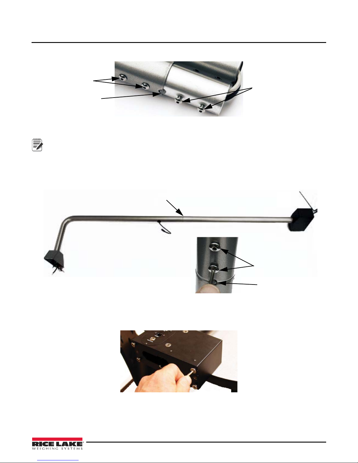
Screws to be removed
Alignment Point
Screws to be left
in place
Note
Pole Intersection
Retained Screws
Alignment Point
2.1 Pole Assembly
Figure 2-1. Remove Screws
1. Using the appropriate hex wrench, remove the two screws at the pole joint. Retain the screws for assembly.
Leave the other two screws in place.
2. Lay the pole out on a hard surface covered with a rug or similar soft covering.
3. Ensure that the poles are aligned correctly using the notch and pin as a guide.
4. Insert the lower half of the pole into the upper half.
5. Reinsert and tighten the screws removed in step 1.
6. Lay the pole assembly on a table or other stable surface. Ensure the power block is hanging over the edge.
7. Remove the four screws that are in the bottom of the power block.
8. Insert the two pins on the base into the matching holes of the power block.
9. Reinsert and tighten the four bolts removed in step 7.
Figure 2-2. Pole Assembly
Figure 2-3. Remove Power Block Screws
Assembly 3
Page 8

Figure 2-4. Pole Assembly
Cable Shroud
Display Cable
Power Block
Base
Screws
Slide direction
10. Stand the assembled pole upright.
2.2 Head Attachment
Figure 2-5. Remove Cable Shroud Cover
1. Loosen the four screws that secure the cable shroud cover. Do not remove them.
2. Slide the shroud cover back and lift it off.
3. Align the head with the cable shroud at the top of the pole.
4. Connect the cables. See Figure 2-7.
4 iDimension 100 Assembly Instructions
Figure 2-6. Align Head with Shro u d
Page 9

Figure 2-7. Cabl e Co n nections
The cables and ports on back of the head are
labeled for easy connections.
Note
Keyhole
Slots
Cable Order Cable Label Port Label
1 Ethernet Ethernet
2 USB 3 USB 3
3 USB 2 USB 2
4 Auxiliary power only Power only 1
5 24 VDC in Input: 24v
Table 2-1. Cable Connectio ns
5. Push the cables into the cable shroud carefully.
6. Insert the screws on the head into the keyhole slots on the shroud. Do not tighten them yet.
Figure 2-8. Connected Cables
Assembly 5
Page 10

Figure 2-9. Reinstall Shroud Cover
Shroud Cover
U-Shaped
Bracket
7. Place the shroud cover in the cable shroud and slide it forward until it clicks into place.
8. Re-tighten the fours screws that secure it.
Figure 2-10. T ighten Head Screws
9. Tighten the bolts that attach the head to the shroud.
2.3 Display Assembly
1. Loosen the bolt that holds the u-shaped display bracket.
6 iDimension 100 Assembly Instructions
Figure 2-11. U-Shaped Display Bracket
Page 11

Figure 2-12. Cable Cover
6
6
Note
2. Remove the cable cover on the back of the display (for attachment of the USB cable in steps 5 and 6).
"
"
Figure 2-13. Select Display Location
3. Select the display location. The display is usually mounted just above the display cable opening.
It’s possible to mount the display up to six inches above or below the opening. This depends on the size of the
items that are to be dimensioned, operator height or other factors (the location can be easily adjusted later).
4. Mount the display to the pole at the selected location by re-tightening the bolt on the u-shaped bracket.
Figure 2-14. Mount Display
Assembly 7
Page 12

Figure 2-15. Insert Display Cable
The Ethernet connector is for
connecting to the network to
perform more advanced
configuration of the device.
The USB port is for attaching a scale that is
compatible with the iDimension 100. See
Operators Manual for compatible scales.
Most scales are equipped with an RS-232
option (an RS-232 to USB adaptor may be
required).
5. Insert the display cable into the mini USB port.
6. Route the USB cable into the cable slot and replace the cover that was removed in step 2 above.
7. Remove the overlay that protects the display screen.
Figure 2-16. USB and Ethernet Ports
8. Attach the power cable to the port labeled Input 24v.
2.3.1 Install Scale (Optional)
When using a scale it should be installed prior to plugging the unit in.
1. When using a scale, place it on the base, centering it from side to side.
2. To place the scale front-to-back, find the small grooves engraved on both edges of the base. Center the
scale between them.
8 iDimension 100 Assembly Instructions
Page 13

3.0 Setup
Up/Down
Check Mark
Thumbs Up
The iDimension 100 is now ready to be plugged in. When it is, the software setup process will begin automatically.
Don’t plug in the unit until there is time to complete all of the setup steps.
Additional setup may be required for connecting a compatible scale, placing the unit in its permanent location or
interfacing to a compatible software program.
When the iDimension 100 is powered up for the first time, the setup wizard will launch automatically.
Figure 3-1. Welcome Screen
1. Touch the Arrow button to begin setup.
2. Review the End User License Agreement (EULA) by using the Up/Down scroll buttons.
3. Press the
Thumbs Up button to confirm the EULA terms and conditions have been read and accepted. Setup
cannot be continued until it is pressed.
4. Press the
Check Mark to continue.
Figure 3-2. User Agreement Screen
Setup 9
Page 14

Figure 3-3. Time Zone Setup
5. Using the Up/Down arrows, select the time zone for the iDimension 100.
6. Press the
Check Mark to continue.
Figure 3-4. Time and Date Setup
7. Using the Up/Down arrows, adjust the date and time if necessary.
8. Press the
Check Mark to continue.
10 iDimension 100 Assembly Instructions
Page 15

Figure 3-5. Base Selection
Note
Note
Zero Height calibration allows iDimension 100 to calculate the distance between the scan head and the base.
The process differs depending on whether the base is flat or uneven.
9. Select the scale base that is being used.
• If the base is a smooth-topped scale or the DimStation base, touch the left button.
• If the base is a scale with an uneven surface (such as rollers), touch the right button.
Figure 3-6. Calibration Screen
If using a smooth-topped scale or base, skip to step 12.
10. If the base is an uneven scale, place the calibration box on top of the scale.
11. Press the
Check Mark to continue.
Setup 11
Page 16

Figure 3-7. Clear Scale
Note
It is important to keep the base clear and unobstructed during zero height calibration, so that it can set Zero
Height accurately.
12. Clear the base.
Figure 3-8. Stand Clear of Device
13. Stand clear of device while the countdown completes.
12 iDimension 100 Assembly Instructions
Page 17

Figure 3-9. Zer o Height Complete
Note
14. If a calibration object was used, remove it from the base.
15. Press the
Check Mark to continue.
Figure 3-10. Identify Scan Area
The Scan Zone (Work Zone) is the area in which the unit looks for motion during the dimensioning of items. For
best performance, adjust this to cover the largest area possible that can be used for scanning items and can
be kept clear of all other objects.
16. Adjust the scan area by dragging each of the four touch points.
17. Press the
Check Mark to continue.
Setup 13
Page 18

Figure 3-11. Set up Complete
18. Press the Check Mark to begin using the iDimension 100.
Figure 3-12. Confirm calibration
19. Test the iDimension 100 to ensure it is properly calibrated. Place the calibration object on the base or scale
and check the displayed dimensions.
20. Dimensions should be:
• Length: 14.0 inches
• Width: 12.0 inches
• Height: 3.0 inches
14 iDimension 100 Assembly Instructions
Page 19

3.1 Advanced configuration with QubeVu Manager
The QubeVu Manager is an optional set of software tools provided to enable advanced configuration. They are not
needed in most cases. They are recommended for use only by a technical systems administrator.
This introduction is not intended as a replacement for complete documentation. Please refer to the QubeVu
Manager Guide for a complete guide to the tools. The latest version of the Manager Guide, along with all other
product documentation, can be downloaded from
3.1.1 Define QubeVu on your Network
QubeVu Manager is accessed via the iDimension 100’s IP address over a wired Ethernet connection. To access
these tools the iDimension 100 must be defined on the network.
The iDimension 100 can be installed as a network device and can be configured with a static IP address or by using
DHCP. Talk to the network administrator to determine the best approach for the enterprise network.
The iDimension 100 is shipped with a dual IP configuration. The network interface will lease an IP address from
any available DHCP server. However, it also has a fixed, fail-safe IP address of 169.254.1.1. If DHCP is preferred,
the network administrator can share the IP address leased by the iDimension 100.
•Configure PC network settings to connect to iDimension 100 on 169.254.1.1
•Connect iDimension 100 to a computer using a standard Ethernet cable
•Configure the computer’s Ethernet interface with an IP address of 169.254.1.10.
•Consult with the network administrator if unsure how to change the computer’s IP address.
www.ricelake.com.
Verify connectivity
Verify the communication between the iDimension 10 0 and the computer.
Use the
ping command to confirm connectivity.
ping 169.254.1.1
If the ping command does not show that the iDimension 100, is responding this may be due to an issue with the
network configuration. Make sure that wireless networking is turned off and then try the ping command again. If
this is still unsuccessful contact the network administrator for further assistance.
Access QubeVu Manager
To view the QubeVu Manager home page, open an Internet browser and enter http://169.254.1.1. If using DHCP,
remember to replace 169.254.1.1 with the IP address provided by the network administrator.
Setup 15
Page 20

16 iDimension 100 Assembly Instructions
Page 21

Page 22

09/21/2015 PN 171899
230 W. Coleman St. • Rice Lake, WI 54868 • USA
U.S. 800-472-6703 • Canada/Mexico 800-321-6703 • International 715-234-9171 • Europe +31 (0)26 472 1319
www.ricelake.com www.ricelake.mx www.ricelake.eu www.ricelake.co.in m.ricelake.com
Rice Lake Weighing Systems is an ISO 9001 registered company.
© Rice Lake Weighing Systems Specifications subject to change without notice.
 Loading...