

Page 1
Re:connect M219
V
Nebenraumverstärker M219
Artikel-Nr.: 1.551.060.00
Installationsanleitung
Der M219 ist ein digitaler Nebenraumverstärker der M-Serie im
REVOX Multiroom-Programm. Er dient zur Wiedergabe von Musik
in den Nebenräumen und kann den Zuhörer durch ein Zusatzdisplay mit aktuellen Informationen versorgen.
Eine nicht fachgerechte Montage dieses Geräts in
einer Umgebung mit Niederspannungserzeugnissen
(230V) kann schwerste gesundheitliche oder
materielle Schäden verursachen.
Der Nebenraumverstärker M219 darf nur von qualifiziertem
Personal montiert, angeschlossen oder entfernt werden.
Qualifiziertes Personal sind Personen, die aufgrund ihrer
Ausbildung, Erfahrung und Unterweisung über einschlägige
Normen, Bestimmungen und Unfallverhütungsvorschriften
berechtigt sind, die erforderlichen Tätigkeiten auszuführen und
dabei mögliche Gefahren erkennen und vermeiden können.
Die Angaben und Anweisungen in dieser Installationsanleitung
müssen zur Vermeidung von Gefahren und Schäden stets
beachtet werden.
Installation und Betrieb
Bitte untersuchen Sie das Gerät und Zubehör nach dem Auspacken
auf Transportschäden. Vor Inbetriebnahme des Gerätes lesen Sie bitte
die Bedienungsanleitung sorgfältig durch. Bewahren Sie sie als
Nachschlagewerk auf. Ein Gerät, welches mechanische
Beschädigungen aufweist oder in welches Flüssigkeit eingedrungen
ist, darf nicht ans Netz angeschlossen werden.
Verwenden Sie nur das mitgelieferte Netzkabel. Vor dem Anschluss an
das Netz müssen die Stromversorgungs- und Anschlusswerte des
Gerätes (Netzspannung, Frequenz) überprüft werden. Die im Gerät
eingesetzten Sicherungen müssen den Werksangaben entsprechen.
Stellen Sie den M219 so auf, dass die Lüftungsschlitze nicht verdeckt
werden und dass zu Mauern und Möbeln ein Abstand von min. 5 cm
eingehalten wird. Vermeiden Sie Aufstellungsorte mit:
- direkter Sonneneinstrahlung
- direkt neben Wärmequellen
- schlechter Belüftung
- staubiger Atmosphäre
- instabiler Lage
- Spritzwassergefahr
- hoher (Luft-) Feuchtigkeit
Zudem dürfen keine offenen Feuerquellen (z.B. Kerzen) oder mit
Flüssigkeiten gefüllte Gefäße (z.B. Vasen) auf dem Gerät platziert
werden.
[4] Anschluss M219-LINK
Anschluss für Display M217
Der Anschluss erfolgt über ein nicht gekreuztes, 4-adriges
Telefonkabel (4x1x 0.5mm²) mit RJ11-Stecker (6P4C-Modular) mit
der M219 LINK-Buchse.
Max. Kabellänge (ü.a.) : 100 m
[5] Anschluss IR-LINK
Anschluss für die Wandbedienung M218 oder den IREmpfänger M204.
Revox empfiehlt für die Verkabelung ein 3-adriges Mikrofonkabel
mit Abschirmung. Bei Verwendung einer M217-M218-Kombi erfolgt
die Verkabelung der Wandbedienung direkt am Display !
Max. Anzahl von IR-Empfängern bzw.
Wandbedienungen pro M219: 3 St.
Max. Kabellänge (ü.a.) : 40 m
Revox GmbH Tel: +49 (0) 7721-8704-0 © Revox GmbH 2005 - Alle Rechte vorbehalten
Am Krebsgraben 15 Fax: +49 (0) 7721-8704-49
78048 VS-Villingen info@revox.de
Germany www.revox.de
M217
VCC
GND
B
A
M219-Link
Phoenix-4 RJ11
IR-LinkM218 / M204
VCC - Positive Spg.
IR - Data
GND - GND
Phoenix-3
GND
CC
B
A
+
IN
-
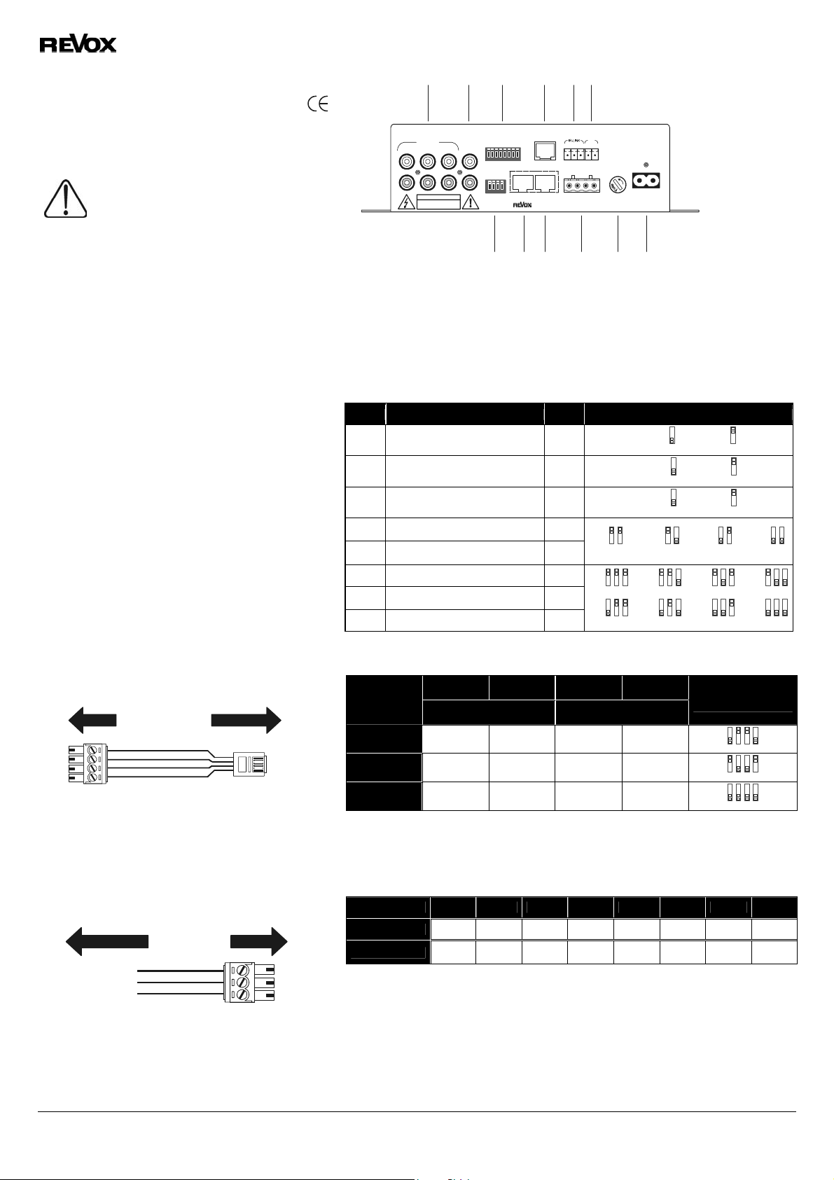
[1] [2] [3] [4] [5] [6]
12
L
R
LOCAL IN
RiSK OF ELECTRIC SHOCK
CAUTION
DO NOT OPEN
PRE
SETUP
OUT
3
1432 5678
ON
1432
ON
CHANNEL
SELECT
M219
LINK
OUT
IN
MR-BUS SPEAKERS
--
IN
+
+ R - - L +
IN
+
115V / T1A L
FUSEAC - POWER
230V / T0,5A L
[1] Lokale Cinch-Eingänge L/R
[2] Vorverstärkerausgang L/R
Setup-DIL Schalter
[3]
Display-Anschluss M219-Link
[4]
Anschluss für IR-Empfänger
[5]
oder Wandbedienung
Spannungseingang IN 5-24 V(=)
[6]
[7] [8] [9] [1 0] [11] [12]
[7]
Stereo/ Mono-Schalter
Eingang Multiroom-Bus
[8]
Ausgang Multiroom-Bus
[9]
Lautsprecheranschluss L/R - Max. 4 mm²
[10]
Sicherung 230 V-0.5 A T bzw. 115V-1.0 A T
[11]
Netzanschluss 230V ~ bzw. 115 V~
[12]
[3] Funktion DIL-Schalter 8-fach / SETUP
NO Funktion Werk DIL-Position
1 M219 IR-Auge Ein/ Aus On
2 Pre-Out: Fixed Volume Off
3 LOCAL IN 1 Æ Fixed Volume Off
4 Anzahl der lokalen Eingänge On
5 Anzahl der lokalen Eingänge On
6 M219-Adresse Off
7 M219-Adresse Off
8 M219-Adresse Off
b
c
g
IR-Ein 1 IR-Aus 1 :
Fixed 2 Floating 2
Fixed 3 Floating 3
4
678
678
5
c
d
h
4
678
678
5
d
e
i
4
678
678
5
e
f
j
[7] Funktion DIL-Schalter 4-fach / CHANNEL SELECT
Betriebsart
Stereo On Off Off On
Invers-Stereo Off On On Off
Mono On On On On
[8] [9] Multiroomverkabelung
Der Aufbau der Multiroomverkabelung erfolgt nach der internationalen Netzwerknorm EIA/TIA-568-B mit
einem geschirmten und ungekreutzten CAT 7-Kabel. Diese EIA/TIA- 568-B Norm sieht folgende
Zuweisung vor:
Klemme 1 2 3 4 5 6 7 8
Farbcode ws/or or ws/gn bl ws/bl gn ws/bn bn
MR-Signal RX TX L+ R+ R- L- GND
DIL- 1
Schalter
DIL- 2
Schalter
DIL- 3
Schalter
Linker Kanal Rechter Kanal
DIL- 4
Schalter
DIL-Position
3
14
2
3
14
2
3
14
2
Technische Daten
Leistungsaufnahme: Max. 115 Watt
Betrieb:
Standby: 2 Watt
7 Watt* *
bei Zimmerlautstärke ohne Zusatzgeräte
Sicherung 230V: 0,5 A Träge 115V: 1,0 A Träge
Betriebsbedingungen: "+10°... +40°C" (Feuchteklasse nach DIN 40040)
Irrtümer und technische Änderungen vorbehalten.
Installationsanleitung M219 Nebenraumverstärker / Artikel-Nr.: 10.30.3038
678
678
MR
GND
5
4
Page 2
Re:connect M219
V
Additional room amplifier M219
Article no.: 1.551.060.00
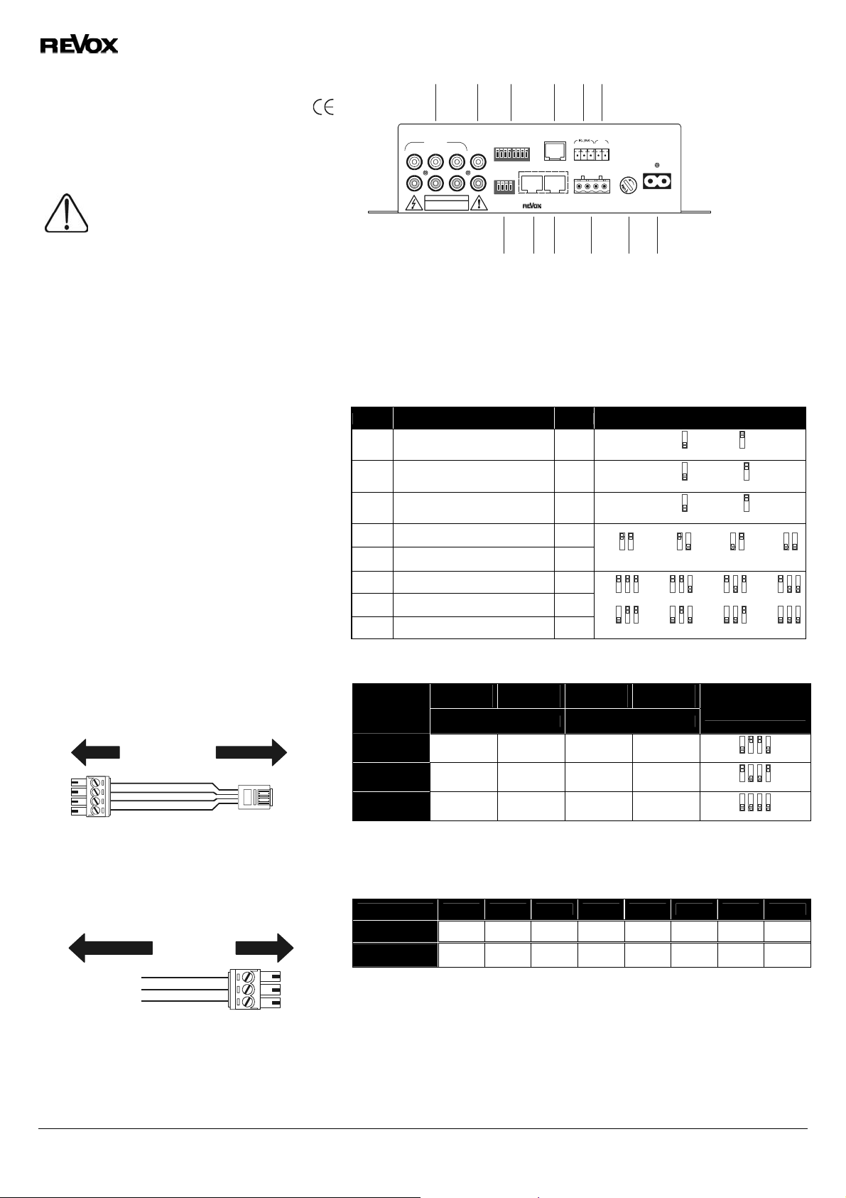
[1] [2] [3] [4] [5] [6]
Installation
The M219 is a digital Additional Room Amplifier from the M Series
of the REVOX Multiroom programme. It is used for the reproduction
of music in the additional rooms in a Multiroom system and can
also supply the listener with current information through an
additional display.
A unprofessional assembly of this equipment in
an environment with products of low-voltage
12
L
R
LOCAL IN
RiSK OF ELECTRIC SHOCK
CAUTION
DO NOT OPEN
PRE
SETUP
OUT
3
1432 5678
ON
1432
ON
CHANNEL
SELECT
(230V) can cause heaviest health or material
damage.
The additional room amplifier M219 may be installed, attached
or removed only from qualified personnel. Qualified
personnel are persons, who are entitled due to its training,
experience and instruction regarding relevant standards,
regulations and rules for the prevention of accidents, who can
implement necessary activities and recognize and avoid
possible dangers. The data and instructions in this
installation guide must be considered for the avoidance of
dangers and damage.
[1] Local Cinch inputs L/R
Preamp outputs L/R
[2]
DIL setup switches
[3]
M219-Link display connector
[4]
IR receiver or keypad connections
[5]
Voltage trigger IN 5-24 V(=)
[6]
[7] [8] [9] [1 0] [11] [12]
Installation and operation
Please check the unit and accessories for any signs of transit
damage, once you have unpacked it. Please read the operating
instructions carefully before starting to use the unit. Keep the
documentation somewhere safe for future reference. If the unit
shows any signs of damage or has come into contact with any
fluids should not be connected to a power supply.
[3] Function DIL switch 8-fold / SETUP
NO Function Factory DIL-Position
1 M219 IR-eye On/ off On
Only use the power cable supplied. Before connecting the power,
the power supply and unit connection values (power voltage,
frequency) must be checked. The fuse used in the unit must
2 Pre-Out: Fixed Volume Off
conform to the factory definitions.
The M219 should be installed in such a way that the ventilation
slots are not covered up and so that there is a gap of at least 5 cm
( ≈ 2 in) between the unit and any walls or furniture.
You should avoid installing it in locations where:
- there is direct sunlight
- it is next to a heat source
- there is poor ventilation
- there is a lot of dust in the atmosphere
- it is unstable
- there is a risk of splashing
- there is high humidity
3 LOCAL IN 1 Æ Fixed Volume Off
4 Number of local inputs On
5 Number of local inputs On
6 M219-address Off
7 M219-address Off
8 M219-address Off
Furthermore you may not place objects filled with liquids, such as
vases, or naked flame sources, such as lighted candles, on the
M219.
[4] M219-LINK
M217- Display connection
M217
M219-Link
[7] Function DIL switch 4-fold / CHANNEL SELECT
DIL- 1
Operating
mode
Stereo On Off Off On
Switch
Left channel Right channel
Phoenix-4 RJ11
Connection is made using a straight through (not crossed), 4-core
VCC
GND
B
A
GND
CC
B
A
telephone cable (4x1x0.5mm²) with an RJ11 plug (6P4C-Modular)
connected to the M219 LINK socket.
Max cable length (o.a.) : 100m – 330 ft
[5] IR-LINK
Connection for the external IR-receiver M204 or the keypad M218.
VCC - Positive Spg.
IR - Data
GND - GND
REVOX recommends the use of a 3-core, screened
cable.
When using a M217-M218-combination the wiring of the keypad
takes place directly at the display!
Max no. of IR receivers or keypads per M219 is 3.
Max cable length (o.a.) : 40m – 133 ft
Revox GmbH Tel: +49 (0) 7721-8704-0 © Revox GmbH 2005 - Alle Rechte vorbehalten
Am Krebsgraben 15 Fax: +49 (0) 7721-8704-49
78048 VS-Villingen info@revox.de
Germany www.revox.de
IR-LinkM218 / M204
Phoenix-3
microphone
+
IN
-
Invers-Stereo Off On On Off
Mono On On On On
[8] [9] Multiroom cabling
Multiroom cabling uses a CAT 7 cable, in accordance with the international network standard
EIA/TIA-568-B. This EIA/TIA-568-B standard provides for the following assignment
Clamp 1 2 3 4 5 6 7 8
Colour code wh/or or wh/gn bl wh/bl gn wh/bn bn
MR-signal RX TX L+ R+ R- L- GND
Technical Data
Power consumption: Max. 115 Watt
Operation:
Standby: 2 Watt
Fuse 230V: 0,5A time-lag 115V: 1,0A time-lag
Operation conditions:
Errors and technical modifications excepted
Instruction manual sideroom amplifier M219 / part no.: 10.30.3038
"+10°... +40°C"
IN
DIL- 2
Switch
M219
LINK
OUT
MR-BUS SPEAKERS
IN
--
IN
+
+
115V / T1A L
+ R - - L +
[7]
[8]
[9]
[10]
FUSEAC - POWER
230V / T0,5A L
Stereo/ Mono switch
Multiroom b us input
Multiroom bus output
Speaker connections L/R - Max. 4 mm² - AWG12
[11] Fuse 230 V-0.5 A T resp. 115V-1.0 A T
Power connection 230V ~ resp. 115 V~
[12]
IR-On 1 IR-Off 1 :
Fixed 2 Floating 2
Fixed 3 Floating 3
b
c
g
DIL- 3
Switch
7 Watt* *
4
678
678
5
c
d
h
678
678
DIL- 4
4
5
d
e
i
5
4
e
678
f
678
j
DIL Position
Switch
3
14
2
3
14
2
3
14
2
at room volume without additional devices
/ “+50°…+104°F” (Humidity rating acc. DIN 40040)
678
678
MR
GND
5
4
 Loading...