

REVELL Huey Chopper User Manual [en, fr, nl, it, gr, da, no, fi, sv, es, pt, de, en, hr, et, fi, hu, lv, lt, nl, pl, ro, ru, sr, sk, sl, cs, tr, gr, bg, uk, ch, he, ar, ja, ch, ch, ko, hi, id, kk, ms, fa, pt, es, th, vi, sq, mk]
Page 1
®
During the 1960’s, the
lack of effective close
air support aircraft led
to the creation of the
Bell UH-1B “Huey”
Gunship. Fitted with
various guns, these
armed helicoptors were
used quite successfully in Southwest Asia.
Your Revell model is
tted with two externally
mounted .50 caliber ma-
chine gun pods and spinning main and tail rotors.
KIT 1743
85174310200
HUEY CHOPPER
* APPLY STICKER
* APPLIQUEZ LES AUTO-COLLANTS
READ BEFORE YOU BEGIN
• CLEAR A SPACE TO WORK ON
• STUDY THE ASSEMBLY DRAWINGS
BEFORE YOU BEGIN
• EACH PLASTIC PART IS IDENTIFIED BY
A PART NUMBER
• SEE NOTE ABOUT APPLYING
STICKERS IN STEP #7
CAUTION:
POSITION ALL PARTS IN THIS KIT
CAREFULLY. PARTS WILL ONLY SNAP
TOGETHER ONCE.
If you have any questions or comments, call our hotline at: (800) 833-3570
Revell Inc Consumer Service Department, 1840 Howard Street Unit A, Elk Grove Village, Illinois 60007
Be sure to include the plan number (85174310200), part number, description, your return address and phone number.
Revell Inc Elk Grove Village, IL. Copyright © 2009. All rights reserved.
* REPEAT SEVERAL TIMES
* A REPETER PLUSIEURS FOIS
Á LIRE AVANT DE COMMENCER
• DÉGAGGEZ UN ESPACE POUR
TRAVAILLER.
• ÉTUDIEZ LES ÉTAPES DE MONTAGE
AVANT DE COMMENCER.
• CHAQUE PIÉCE EN PLASTIQUE PORTE
UN NUMÉRO DE PIÉCE.
• LISEZ LA RE MARQUE CONCERNANT
L´APPLICATION DES AUTO-COLLANTS,
´A L´ ÉTAPE 7.
POSITIONNEZ AVEC PRÉCAUTION
TOUTES LES PIÉCES DE CE MODÉLE
RÉDUIT, CAR VOUS NE POUVEZLES
EMBOîTER QU’UNE SEULE FOIS.
or, please write to:
Visit our website: www.revell.com
MISE EN GARDE:
* REMOVE AND THROW AWAY
* A RETIRER ET JETER
Page 2
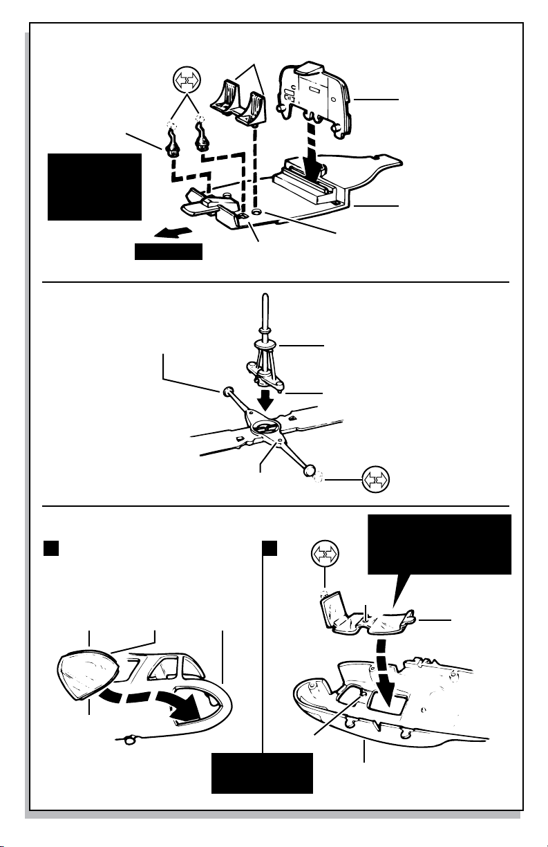
Step 1
8
CONTROL
STICK
Place control
stick into “t”
slot and Push
forward into
Place
Step 2
forward
9
SEATS
7
WALL
6
FLOORBOARD
HOLE
“T” SHAPED SLOT
Step 3
A
20
WINDOW
BOTTOM EDGE
11
ROTOR
TOP EDGE
1R
FUSELAGE
HOLE
10
SHAFT
PIN
first Place bottom edge of
B
PIN
windows into inside of fuse-
lage oPening then snaP toP
edge into the oPening
HOLE
WINDOWS
19
KIT 1743 Page - 1
rePeat for left
side using Parts #1l,
fuselage, #26 window,
#27 windows
1R
FUSELAGE
Page 3

Step 4
1L
FUSELAGE
NOTCH NOTCH
1R
FUSELAGE
Step 5
Step 6
3
STABILIZER
5
SHAFT
SLOT
4
ROTOR
22
STABILIZER
12
GUN POD
firstsecond
13
SUPPORT
2
SKID
12
GUN POD
KIT 1743 Page - 2
Page 4

132
1 3 2
4
Step 7 Sticker Placement Guide
NOTE: When applying stickers, avoid touching the “sticky” side to prevent finger prints on stickers. Bend sticker sheet slightly
to lift edge of sticker & use a fingernail to lift sticker from sheet. Line up sticker on body and carefully press an edge
into place, slowly working sticker with a fingernail until sticker is fully on model.
REMARQUE : Pendant l’application des autocollants, éviter de toucher à la face collante pour ne pas laisser d’empreintes.
Plier légèrement la feuille d’autocollants pour relever le bord d’un autocollant, et le détacher de la feuille avec le
bout d’un ongle. Aligner l’autocollant sur la carrosserie, appuyer pour coller un de ses bords, et continuer de
l’appliquer lentement du bout de l’ongle jusqu’à ce qu’il soit complètement collé sur le modèle réduit.
KIT 1743 Page - 3
 Loading...