

Page 1
Manual
Cyclone Mill Twister
Translation
© Retsch GmbH, 42781 Haan, Retsch-Allee 1-5, Germany 06.03.2013 0008
Page 2

Copyright
© Copyright by
Retsch GmbH
Haan, Retsch-Allee 1-5
D-42781 Haan
Federal Republic of Germany
2
Page 3

1 Notes on the Operating Manual ............................................................................................................ 5
1.1 Explanations of the safety warnings .................................................................................................. 6
1.2 General safety instructions ................................................................................................................ 7
1.3 Repairs ............................................................................................................................................... 8
2 Confirmation ........................................................................................................................................... 9
3 Transport, scope of delivery, installation .......................................................................................... 10
3.1 Packaging ........................................................................................................................................ 10
3.2 Transport.......................................................................................................................................... 10
3.3 Temperature fluctuations and condensed water ............................................................................. 10
3.4 Conditions for the place of installation ............................................................................................. 10
3.5 Installation of the machine ............................................................................................................... 10
3.6 Type plate description ...................................................................................................................... 10
3.7 Electrical connection ........................................................................................................................ 11
4 Technical data ....................................................................................................................................... 12
4.1 Use of the machine for the intended purpose.................................................................................. 12
4.2 Working instructions ........................................................................................................................ 12
4.3 Protective equipment ....................................................................................................................... 13
4.4 Drive output...................................................................................................................................... 13
4.5 Rated power .................................................................................................................................... 13
4.6 Motor rotation speed ........................................................................................................................ 13
4.7 Rated voltage ................................................................................................................................... 13
4.8 Emissions......................................................................................................................................... 14
4.9 Degree of protection ........................................................................................................................ 14
4.10 Dimensions and weight .................................................................................................................... 14
4.11 Required floor space ........................................................................................................................ 14
5 Operating the machine ........................................................................................................................ 15
5.1 Views of the Instrument ................................................................................................................... 15
5.2 Overview table of the parts of the device ........................................................................................ 17
5.3 Operating elements and displays .................................................................................................... 17
5.4 Overview Table of the Operating Elements and the Display ........................................................... 18
5.5 Operating the Device ....................................................................................................................... 19
5.6 Switching On and Off ....................................................................................................................... 19
5.7 Opening and closing of the grinding chamber ................................................................................. 20
5.8 Inserting sample vessel ................................................................................................................... 21
5.9 Setting the Speed ............................................................................................................................ 22
5.10 Starting the grinding process ........................................................................................................... 22
5.11 Stopping the grinding process ......................................................................................................... 23
5.12 Mounting the Feed Hopper .............................................................................................................. 23
3
Page 4

5.13 Slider ................................................................................................................................................ 24
5.14 Cyclone assembly ............................................................................................................................ 25
5.14.1 Cyclone assembly with filter bag ............................................................................................. 25
5.14.2 Cyclone assembly with extraction............................................................................................ 25
5.15 Removing and inserting the rotor .................................................................................................... 26
5.16 Replacing the friction insert ............................................................................................................. 27
5.17 Dismantle the cyclone cassette ....................................................................................................... 29
5.18 Replacing the machine fuses........................................................................................................... 30
5.19 Resetting the overload protection .................................................................................................... 30
6 Cleaning and service ........................................................................................................................... 31
7 Fault messages ..................................................................................................................................... 33
8 Disposal ................................................................................................................................................. 34
9 Index ...................................................................................................................................................... 35
Appendix ............................................................................................................................... following pages
4
Page 5

Notes on the Operating Manual
Pos: 1.1 /00005 Überschriften/1. Übersc hriften/1 Hinweise zur Bedienungsanleitung @ 0\mod_1222347415287_9.doc @ 2 631 @ 1 @ 1
1 Notes on the Operating Manual
Pos: 1.2 /00010 Bedienungsanleitungen Kapitelsammlungen/CryoMill/0001 Hinweis e zur Bedienungsanleitung/Modul Hinweis zur Bedienungsanleitung @ 0\mod_ 1222347341773_9.doc @ 2540 @ @ 1
This operating manual is a technical guide on how to operate the device safely and
it contains all the information required for the areas specified in the table of
contents. This technical documentation is a reference and instruction manual. The
individual chapters are complete in themselves.
Familiarity (of the respective target groups defined according to area) with the
relevant chapters is a precondition for the safe and appropriate use of the device.
This operating manual does not contain any repair instructions. If faults arise or
repairs are necessary, please contact your supplier or get in touch with Retsch
GmbH directly.
Application technology information relating to samples to be processed is not
included but can be read on the Internet on the respective device’s page at
Pos: 1.3 /00010 Bedienungsanleitungen Kapitelsammlungen/CryoMill/0001 Hinw eise zur Bedienungsanleitung/Modul Änder ungen @ 0\mod_1222347341241_9.doc @ 2526 @ @ 1
www.retsch.com.
Changes
Pos: 1.4 /00010 Bedienungsanleitungen Kapitelsammlungen/CryoMill/0001 Hinweis e zur Bedienungsanleitung/Modul Urhe berrecht @ 0\mod_1222347342038_9.d oc @ 2547 @ @ 1
Subject to technical changes.
Pos: 2.1 /00010 Bedienungsanleitungen Kapitelsammlungen/------- Seitenumbruch ----------- @ 0\mod_1222344373758_ 0.doc @ 2386 @ @ 1
Copyright
Disclosure or reproduction of this documentation, use and disclosure of its contents
are only permitted with the express permission of Retsch GmbH.
Infringements will result in damage compensation liability.
5
Page 6
Notes on the Operating Manual
WARNING
Type of danger / personal injury
Source of danger
– Possible consequences if the dangers are not observed.
• Instructions on how the dangers are to be avoided.
WARNING
CAUTION
Type of danger / personal injury
Source of danger
– Possible consequences if the dangers are not observed.
• Instructions on how the dangers are to be avoided.
CAUTION
NOTICE
Nature of the property damage
Source of property damage
– Possible consequences if the instructions are not observed.
• Instructions on how the dangers are to be avoided.
Pos: 2.2 /00005 Überschriften/1.1 Überschrif ten/1.1 Überschriften BDA/11 Er klärungen zu den Sicherheitswarnungen @ 0\ mod_1222344569771_9.doc @ 2484 @ 2 @ 1
1.1 Explanations of the safety warnings
Pos: 2.3 /00003 Standard Kapitel/General Modul Warnhinweise Erklärung neu @ 0\ mod_1234858329746_9.doc @ 6190 @ @ 1
In this Operating Manual we give you the following safety warnings
Serious injury may result from failing to heed these safety warnings. We give you
the following warnings and corresponding content.
We also use the following signal word box in the text or in the instructions on action
to be taken:
Moderate or mild injury may result from failing to heed these safety warnings.
We give you the following warnings and corresponding content.
Pos: 2.4 /00010 Bedienungsanleitungen Kapitelsammlungen/------- Seitenumbruch ----------- @ 0\mod_1222344373758_ 0.doc @ 2386 @ @ 1
We also use the following signal word box in the text or in the instructions on action
to be taken:
In the event of possible property damage we inform you with the word
“Instructions” and the corresponding content.
We also use the following signal word in the text or in the instructions on action to
be taken:
NOTICE
6
Page 7
Notes on the Operating Manual
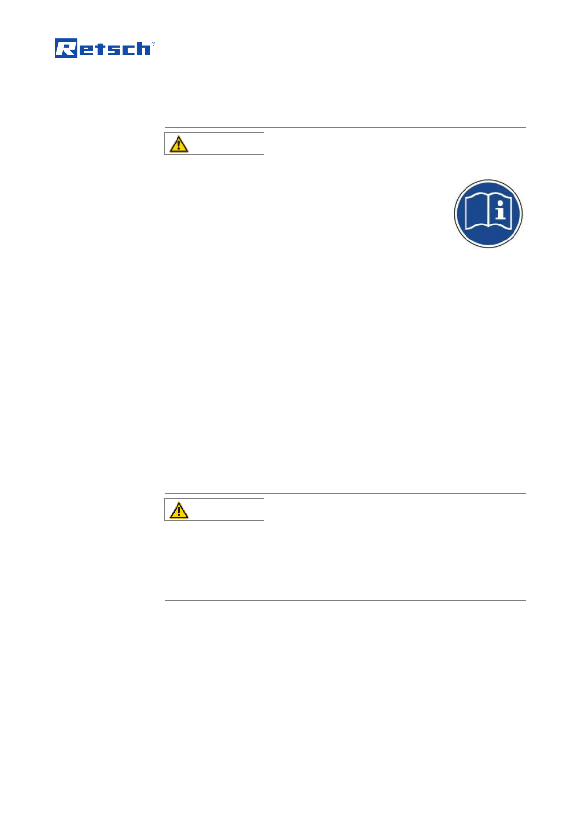
CAUTION
Read the Operating Manual
Non-observance of these operating instructions
– The non-observance of these operating instructions can
result in personal injuries.
• Read the operating manual before using the device.
• We use the adjacent symbol to draw attention to the
necessity of knowing the contents of this operating
manual.
CAUTION
Changes to the machine
– Changes to the machine may lead to personal injury.
• Do not make any change to the machine and use spare parts and
accessories that have been approved by Retsch exclusively.
NOTICE
Changes to the machine
– The conformity declared by Retsch with the European Directives will lose
its validity.
– You lose all warranty claims.
• Do not make any change to the machine and use spare parts and
accessories that have been approved by Retsch exclusively.
Pos: 2.5 /00005 Überschriften/1.1 Überschrif ten/1.1 Überschriften BDA/11 Generelle Sicherheitshinweise @ 0\mod_122 2344568974_9.doc @ 2463 @ @ 1
1.2 General safety instructions
Pos: 2.6 /00004 Warnhinweise/V0002 VORS ICHT Bedienungsanleitung lesen @ 2\ mod_1263894982815_9.doc @ 1863 0 @ @ 1
Pos: 2.7 /00003 Standard Kapitel/General Modul Zielgruppe und Sicherheit @ 0 \mod_1228722955300_9.doc @ 4100 @ @ 1
Target group : All persons concerned with the machine in any form
This machine is a modern, high performance product from Retsch GmbH and
complies with the state of the art. Operational safety is given if the machine is
handled for the intended purpose and attention is given to this technical
Pos: 2.8 /00003 Standard Kapitel/General Modul Sicherheitshinweise @ 0\mod_ 1228722954800_9.doc @ 4086 @ @ 1
Pos: 2.9 /00004 Warnhinweise/V0015 VORS ICHT + HINWEIS Sach- und Person enschäden @ 1\mod_1236238456676_9 .doc @ 7642 @ @ 1
documentation.
You, as the owner/managing operator of the machine, must ensure that the people
entrusted with working on the machine:
• have noted and understood all the regulations regarding safety,
• are familiar before starting work with all the operating instructions and
specifications for the target group relevant for them,
• have easy access always to the technical documentation for this machine,
• and that new personnel before starting work on the machine are familiarised
with the safe handling of the machine and its use for its intended purpose,
either by verbal instructions from a competent person and/or by means of
this technical documentation.
Improper operation can result in personal injuries and material damage. You are
responsible for your own safety and that of your employees.
Make sure that no unauthorised person has access to the machine.
Pos: 2.10 /00010 Bedienungsanleitungen K apitelsammlungen/------- Seitenumbruch ----------- @ 0\mod_1222344373758 _0.doc @ 2386 @ @ 1
7
Page 8

Notes on the Operating Manual
The Retsch representative in your country
Your supplier
Retsch GmbH directly
Pos: 2.11 /00005 Überschriften/1.1 Übersc hriften/1.1 Überschriften BDA/11 Reparat uren @ 0\mod_1223624336511_9.doc @ 2978 @ @ 1
Reperaturen
1.3 Repairs
Pos: 2.12 /00003 Standard Kapitel/Gen eral Modul Reparaturen @ 0\mod_1228 722954535_9.doc @ 4079 @ @ 1
This operating manual does not contain any repair instructions. For your own
safety, repairs may only be carried out by Retsch GmbH or an authorized
representative or by Retsch service engineers.
In that case please inform:
Your Service Address:
Pos: 3.1 /00020 BDA Software/20005 PM GC Kapitelsammlung/- - - - Seitenum bruch - - - - @ 0\mod_1208857688413_0.doc @ 337 @ @ 1
8
Page 9

Confirmation
I have read and taken note of the contents of all chapters in this operating
manual as well as all safety instructions and warnings.
User
Surname, first name (block letters)
Position in the company
Signature
Service technician or operator
Surname, first name (block letters)
Position in the company
Place, date and signature
Pos: 3.2 /00020 BDA Software/20005 PM GC Kapitelsammlung/Überschriften/1. Üb erschriften/1 Bestätigung (Formular für den Betreiber) @ 0\mod_1208870841095 _9.doc @ 430 @ 1 @ 1
Bestätigung
2 Confirmation
Pos: 3.3 /00003 Standard Kapitel/General Modul Bestätigung @ 0\mod_122872 2962707_9.doc @ 4114 @ @ 1
This operating manual contains essential instructions for operating and maintaining
the device which must be strictly observed. It is essential that they be read by the
operator and by the qualified staff responsible for the device before the device is
commissioned. This operating manual must be available and accessible at the
place of use at all times.
The user of the device herewith confirms to the managing operator (owner) that
(s)he has received sufficient instructions about the operation and maintenance of
the system. The user has received the operating manual, has read and taken note
of its contents and consequently has all the information required for safe operation
and is sufficiently familiar with the device.
As the owner/managing operator you should for your own protection have your
employees confirm that they have received the instructions about the operation of
the machine.
Pos: 4.1 /00010 Bedienungsanleitungen Kapitelsammlungen/------- Seitenumbruch ----------- @ 0\mod_ 1222344373758_0.doc @ 2386 @ @ 1
9
Page 10

Transport, scope of delivery, installation
NOTICE
Transport
– Mechanical or electronic components may be damaged.
• The machine may not be knocked, shaken or thrown during
transport.
NOTICE
Temperature fluctuations
The machine may be subject to strong temperature fluctuations during transport
(e.g. aircraft transport)
– The resultant condensed water may damage electronic components.
• Protect the machine from condensed water.
NOTICE
Ambient temperature
– Electronic and mechanical components may be damaged and the
performance data alter to an unknown extent.
• Do not exceed or fall below the permitted temperature range of the
machine (5°C to 40°C / ambient temperature).
Pos: 4.2 /00005 Überschriften/1. Überschri ften/1 Verpackung, Transport und Aufst ellung @ 0\mod_1226494451893_9.doc @ 3380 @ 1 @ 1
3 Transport, scope of delivery, installation
Pos: 4.3 /00005 Überschriften/1.1 Überschrif ten/1.1 Überschriften BDA/11 Verpacku ng @ 0\mod_1226495088973_9.doc @ 3392 @ 2 @ 1
3.1 Packaging
Pos: 4.4 /00003 Standard Kapitel/General Modul Verpackung @ 0\mod_12289 84618355_9.doc @ 4892 @ @ 1
Pos: 4.5 /00005 Überschriften/1.1 Überschrif ten/1.1 Überschriften BDA/11 Transp ort @ 0\mod_1226495164391_9.doc @ 3398 @ 2 @ 1
3.2 Transport
Pos: 4.6 /00004 Warnhinweise/H0017 H INWEIS Transport @ 0\mod_122891888 3019_9.doc @ 4802 @ @ 1
Pos: 4.7 /00005 Überschriften/1.1 Überschrif ten/1.1 Überschriften BDA/11 Temperatursc hwankungen @ 0\mod_1226495 190738_9.doc @ 3404 @ 2 @ 1
3.3 Temperature fluctuations and condensed water
Pos: 4.8 /00004 Warnhinweise/H0016 H INWEIS Temperaturschwankungen @ 0\ mod_1233564121287_9.doc @ 5570 @ @ 1
The packaging has been adapted to the mode of transport. It complies with the
generally applicable packaging guidelines.
Pos: 4.9 /00005 Überschriften/1.1 Überschrif ten/1.1 Überschriften BDA/11 Beding ungen für den Aufstellort @ 0\mod_12 26497029322_9.doc @ 3428 @ 2 @ 1
3.4 Conditions for the place of installation
Pos: 4.10 /00003 Standard Kapitel/Gen eral Modul Umgebungstemperatur 5°C - 40°C @ 0\mod_1228918538881_9.doc @ 4745 @ @ 1
Pos: 4.11 /00004 Warnhinweise/H0021 HIN WEIS Umgebungstemperatur 5°C bis 4 0°C @ 0\mod_1228918883441_9.doc @ 4816 @ @ 1
Pos: 4.12 /00005 Überschriften/1.1 Übersc hriften/1.1 Überschriften BDA/11 Aufstell en des Gerätes @ 0\mod_12264988 49756_9.doc @ 3464 @ 2 @ 1
3.5 Installation of the machine
Pos: 4.13 /00003 Standard Kapitel/Gen eral Modul Aufstellungshöhe @ 0\mod_ 1228918538349_9.doc @ 4724 @ @ 1
Pos: 4.14.1 /00005 Überschriften/1.1 Ü berschriften/1.1 Überschriften BDA/11 Type nschild Beschreibung @ 3\mod_128093 3953941_9.doc @ 22302 @ 2 @ 1
Installation height: maximum 2000 m above sea level
3.6 Type plate description
Pos: 4.14.2 /00003 Standard Kapitel/Gen eral Modul Typenschild @ 3\mod_1280 931092443_9.doc @ 22278 @ @ 1
10
Page 11
Transport, scope of delivery, installation
WARNING
1 2 3 4 5 6 7 8 9
10
11
12
14
13
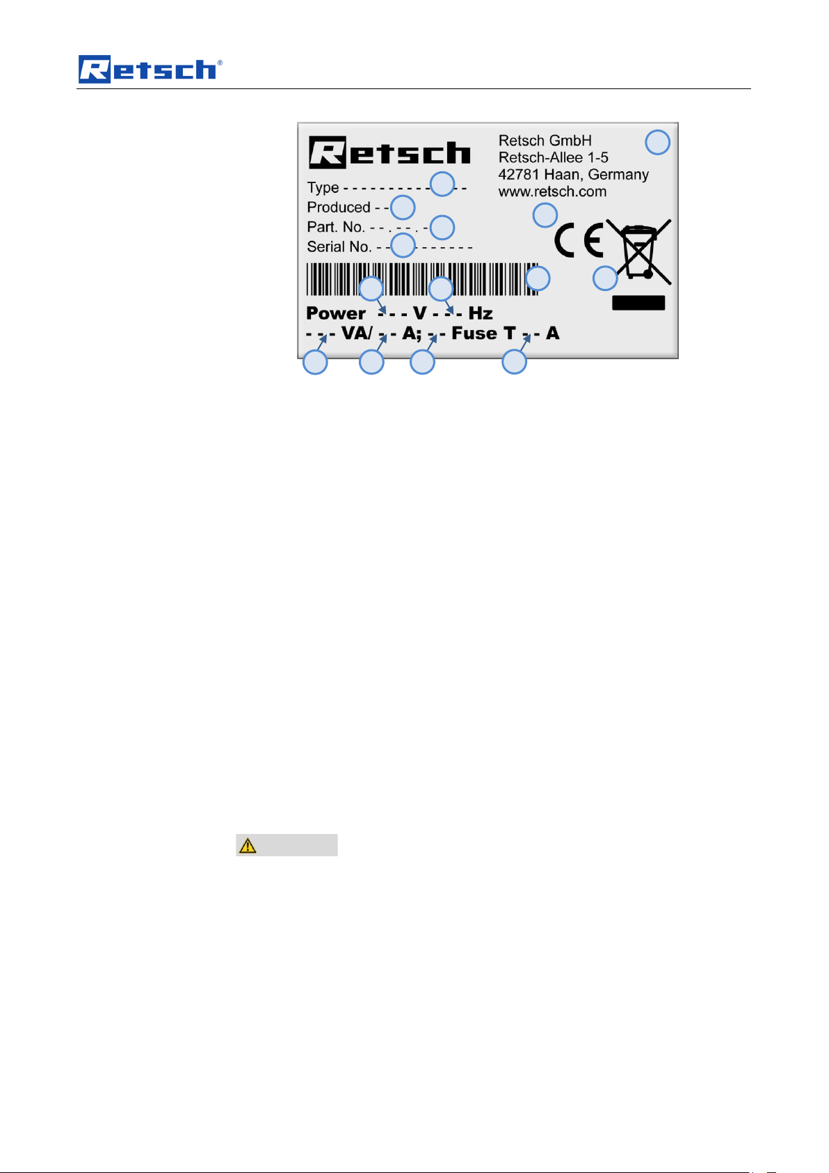
Fig. 1: Type plate lettering
1 Device designation
2 Year of production
3 Part number
4 Serial number
5 Manufacturer’s address
6 CE marking
7 Disposal label
8 Bar code
9 Power version
10 Mains frequency
11 Capacity
12 Amperage
13 Number of fuses
14 Fuse type and fuse strength
In the case of questions please provide the device designation (1) or the part
Pos: 4.15 /00005 Überschriften/1.1 Übersc hriften/1.1 Überschriften BDA/11 Elektrisc her Anschluss @ 0\mod_122656506 7445_9.doc @ 3500 @ 2 @ 1
number (3) and the serial number (4) of the device.
3.7 Electrical connection
Pos: 4.16 /00003 Standard Kapitel/Gen eral Modul Elektrischer Anschluss @ 0\ mod_1228918538521_9.doc @ 4731 @ @ 1
When connecting the power cable to the mains supply, use an external fusethat
complies with the regulations applicable to the place of installation .
Pos: 5 /00010 Bedienungsanleitungen Ka pitelsammlungen/------- Seitenumbruch ----------- @ 0\mod_ 1222344373758_0.doc @ 2386 @ @ 1
• Please check the type plate for details on the necessary voltage and
frequency for the device.
• Make sure the levels agree with the existing mains power supply.
• Use the supplied connection cable to connect the device to the mains power
supply.
11
Page 12
Technical data
CAUTION
1.V0004
Risk of explosion or fire
Changing sample properties
– Consider that the properties and therefore also the hazardousness of your
sample can change during the grinding process.
• Do not use any substances in this device which carry the risk of
explosion or fire.
CAUTION
Risk of explosion or fire
– On account of its design, the device is not suitable for use in hazardous
(potentially explosive) atmospheres.
• Do not operate the device in a hazardous atmosphere.
CAUTION
Danger of personal injury
Dangerous nature of the sample
– Depending on the dangerous nature of your sample, take the
necessary measures to rule out any danger to persons.
• Observe the safety guidelines and datasheets of your
sample material.
Pos: 6.1 /00005 Überschriften/1. Überschri ften/1 Technische Daten @ 0\mod_12 22344525522_9.doc @ 2407 @ 1 @ 1
4 Technical data
Pos: 6.2 /00005 Überschriften/1.1 Überschrif ten/1.1 Überschriften BDA/11 Einsatz der Maschine bei bestimmungsgemäß er Verwendung @ 0\mod_122647673224 8_9.doc @ 3243 @ 2 @ 1
4.1 Use of the machine for the intended purpose
Pos: 6.3 /00004 Warnhinweise/V0004 VORS ICHT Explosions- oder Brandgefa hr Vermahlen @ 1\mod_1236238455830_9 .doc @ 7626 @ @ 1
Pos: 6.4 /00004 Warnhinweise/V0005 VORS ICHT explosionsgefärdete Atmosphäre @ 1\mod_1239868668923_9.doc @ 8140 @ @ 1
Pos: 6.5 /00004 Warnhinweise/V0006 VORS ICHT Gefahr von Personenschäde n Gefährliche Stoffe @ 1\mod_1236238456 269_9.doc @ 7634 @ @ 1
Pos: 6.6 /00010 Bedienungsanleitungen Kapitelsammlungen/Twister Mill (2011)/00 05 Zyklon Mill Twister Technische Daten/05 05 NIR Modul Einsatz bei bestimmungsg emäßer Verwendung @ 3\mod_1284 362103550_9.doc @ 23071 @ @ 1
Target group: operators
Machine type designation: Cyclone Mill - Twister
This machine is intended for the grinding of animal feed, green feed, cereals and
similar dry materials.
The feed size is 10mm.
The device is designed as a laboratory device for 8-hour one-shift operation with a
30% ON duration.
Pos: 6.7 /00005 Überschriften/1.1 Überschrif ten/1.1 Überschriften BDA/11 Funktions weise @ 0\mod_1222344568271_9.do c @ 2442 @ 2 @ 1
Arbeitsweise
It is not intended for use as production machine.
4.2 Working instructions
Pos: 6.8 /00010 Bedienungsanleitungen Kapitelsammlungen/Twister Mill (2011)/00 05 Zyklon Mill Twister Technische Daten/05 10 NIR Modul Funktionsweise @ 3\ mod_1284362211645_9.doc @ 23079 @ @ 1
This device has been developed to prepare samples of animal feed for final NIR
analysis. The optimised form of the rotor and of the grinding chamber generates an
air current which transports the ground material through the integrated cyclone
into the sample vessel. The air current simultaneously prevents the warming of the
sample so that moisture losses are avoided. The sieves supplied guarantee
optimum particle size distribution. The rotor speed can be adjusted in 3 stages and
12
can therefore be adjusted to the requirements of the sample. The cleaning
Page 13
Technical data
requirements are very low in this device because the sample is transported virtually
completely from the grinding chamber.
Advantages at a glance:
• Ideal for the grinding of animal feed, green feed and similar materials
• 3 controlled rotor speeds
• Cyclone with 250 ml collecting receptacle for fast collection of samples
Pos: 6.9 /00005 Überschriften/1.1 Überschri ften/1.1 Überschriften BDA/11 Schutzei nrichtungen @ 0\mod_1226486316130 _9.doc @ 3304 @ @ 1
• Simple and fast cleaning, no cross-contamination
4.3 Protective equipment
Pos: 6.10 /00010 Bedienungsanleitungen K apitelsammlungen/Twister Mill (2011)/0 005 Zyklon Mill Twister Technische Dat en/0515 NIR Modul Schutzeinrichtungen @ 3\mod_1284362213067_9.doc @ 23088 @ @ 1
The grinding chamber of this device is interlocked with a resistant protective hood
with safety switch.
It is only possible to start the device if the protective hood is closed.
Pos: 6.11 /00005 Überschriften/1.1 Übersc hriften/1.1 Überschriften BDA/11 Antrieb @ 1\mod_1240475743011_9.doc @ 8 557 @ @ 1
The device can only be started if cassette and lid are in place.
4.4 Drive output
Pos: 6.12 /00010 Bedienungsanleitungen Kapitelsammlungen/Twister Mill (2011)/0 005 Zyklon Mill Twister Technische Daten/0 520 NIR Modul Antrieb @ 3\mod_1 284362218395_9.doc @ 23169 @ @ 1
Pos: 6.13 /00005 Überschriften/1.1 Übersc hriften/1.1 Überschriften BDA/11 Nen nleistung @ 0\mod_1226491873164_9.doc @ 3334 @ @ 1
Universal series motor
4.5 Rated power
Pos: 6.14 /00010 Bedienungsanleitungen K apitelsammlungen/Twister Mill (2011)/0 005 Zyklon Mill Twister Technische Daten/0 525 NIR Modul Nennleistung @ 3\ mod_1284362220427_9.doc @ 23178 @ @ 1
Pos: 6.15 /00005 Überschriften/1.1 Übersc hriften/1.1 Überschriften BDA/11 Motor drehzahl @ 1\mod_1241508280705_9.d oc @ 8763 @ @ 1
Motor capacity: approx. 900 watts
4.6 Motor rotation speed
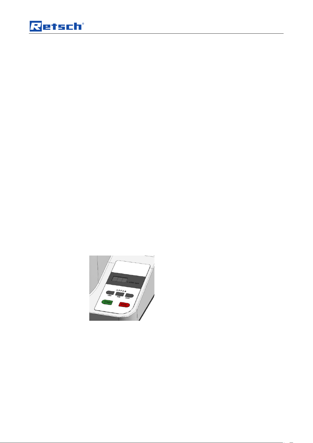
Pos: 6.16 /00010 Bedienungsanleitungen K apitelsammlungen/Twister Mill (2011)/0 005 Zyklon Mill Twister Technische Daten/0 530 NIR Modul Motordrehzahl @ 3\m od_1284362213739_9.doc @ 23097 @ @ 1
The motor speed can be adjusted to three levels:
LOW: 10000 revolutions per minute (10 x 1000 rpm)
MID: 12000 revolutions per minute (12 x 1000 rpm)
HIGH: 14000 revolutions per minute (14 x 1000 rpm)
Pos: 6.17 /00005 Überschriften/1.1 Übersc hriften/1.1 Überschriften BDA/11 Nen nspannungen @ 1\mod_124047602449 4_9.doc @ 8571 @ @ 1
4.7 Rated voltage
Pos: 6.18 /00010 Bedienungsanleitungen K apitelsammlungen/Twister Mill (2011)/0 005 Zyklon Mill Twister Technische Daten/0 535 NIR Modul Nennspannungen @ 3\mod_1284362214380_9.doc @ 23106 @ @ 1
Fig. 2: Setting motor speed
Rated voltages: 220V - 240 V 50/60 Hz (+/- 5%)
110V - 120V 50/60 Hz (+/- 5%)
13
Page 14

Technical data
CAUTION
Possibility of acoustic signals not being heard
Loud grinding noises
- Acoustic alarms and voice communication might not be heard.
• Consider the volume of the grinding noise in relation to other
acoustic signals in the work environment. You may wish to use
additional visual signals.
Pos: 6.19 /00005 Überschriften/1.1 Übersc hriften/1.1 Überschriften BDA/11 Emmisi onen @ 0\mod_1226487095021_9.doc @ 3310 @ @ 1
4.8 Emissions
Pos: 6.20 /00004 Warnhinweise/V0020 VOR SICHT Überhören von akustischen Sign alenLaute Mahlgeräusche @ 1\mod_ 1248185838858_9.doc @ 11740 @ @ 1
Pos: 6.21 /00010 Bedienungsanleitungen Kapitelsammlungen/Twister Mill (2011)/0 005 Zyklon Mill Twister Technische Daten/0 540 NIR Modul Emmisionen @ 3\m od_1284362215005_9.doc @ 23115 @ @ 1
Pos: 6.22 /00005 Überschriften/1.1 Übersc hriften/1.1 Überschriften BDA/11 Schutz art @ 0\mod_1226491839164_9.doc @ 3328 @ @ 1
Noise values: (without sample material)
Noise measurement in accordance with DIN 45635-031-01-KL3
Workplace-related emission value LpAeq
~ 67.5 dB(A) LOW: 10000 revolutions per minute
~ 70.0 dB(A) MID: 12000 revolutions per minute
~ 73.0 dB(A) HIGH: 14000 revolutions per minute
The noise values are also influenced by the properties of the sample medium.
4.9 Degree of protection
Pos: 6.23 /00010 Bedienungsanleitungen K apitelsammlungen/Twister Mill (2011)/0 005 Zyklon Mill Twister Technische Daten/0 545 NIR Modul Schutzart @ 3\mod_ 1284362215536_9.doc @ 23124 @ @ 1
– Grinding chamber and keypad - IP 42
Pos: 6.24 /00005 Überschriften/1.1 Übersc hriften/1.1 Überschriften BDA/11 Abmessu ngen und Gewicht @ 0\mod_122649 2212173_9.doc @ 3352 @ @ 1
– In the area of the ventilation slit - IP 20
4.10 Dimensions and weight
Pos: 6.25 /00010 Bedienungsanleitungen K apitelsammlungen/Twister Mill (2011)/0 005 Zyklon Mill Twister Technische Daten/0 550 NIR Modul Abmessung und Ge wicht @ 3\mod_1284362216145_9.doc @ 23133 @ @ 1
Closed:
Height: 427 mm
Width: 449 mm
Depth : 283 mm
with hood open:
Height: 560 mm
Width: 449 mm
Depth : 396 mm
Pos: 6.26 /00005 Überschriften/1.1 Übersc hriften/1.1 Überschriften BDA/11 Erforderli che Standfläche @ 0\mod_122649 2678414_9.doc @ 3364 @ 2 @ 1
Weight: approx. 14 kg
4.11 Required floor space
Pos: 6.27 /00010 Bedienungsanleitungen K apitelsammlungen/Twister Mill (2011)/0 005 Zyklon Mill Twister Technische Daten/0 555 NIR Modul Standfläche @ 3\mod _1284362216661_9.doc @ 23142 @ @ 1
Width: 449 mm
Pos: 7.1 /00010 Bedienungsanleitungen Kapitelsammlungen/------- Seitenumbruch ----------- @ 0\mod_1222344373758_ 0.doc @ 2386 @ @ 1
Depth: 396 mm
14
Page 15

Operating the machine
G H I J K A B
C
D
E F L D M
Pos: 7.2 /00005 Überschriften/1. Überschri ften/1 Bedienung des Gerätes @ 0\m od_1226565880211_9.doc @ 3519 @ 1 @ 1
5 Operating the machine
Pos: 7.3 /00005 Überschriften/1.1 Überschrif ten/1.1 Überschriften BDA/11 Ansichte n des Gerätes @ 0\mod_122899058 1782_9.doc @ 4966 @ 2 @ 1
5.1 Views of the Instrument
Pos: 7.4 /00010 Bedienungsanleitungen Kapitelsammlungen/Twister Mill (2011)/00 15 Zyklon Mill Twister Bedienung/1570 NIR M odul Ansichten des Gerätes @ 3\ mod_1288694929012_9.doc @ 23910 @ @ 1
Fig. 3: View from the front – hood closed
Fig. 4: View from the front – hood open
15
Page 16

Operating the machine
A B D
L
N
O P S R T E F U C
Fig. 5: View from the front – exploded view
Pos: 7.5 /00010 Bedienungsanleitungen Kapitelsammlungen/------- Seitenumbruch ----------- @ 0\mod_1222344373758_ 0.doc @ 2386 @ @ 1
16
Page 17

Operating the machine
Element
Description
Function
A
Filter sack for cyclone
Filters the escaping air
B
Immersion tube
Separates air current from sample material
C
Cyclone cassette
Guides the ground sample to the cyclone
D
Cassette lid
Closes the cassette
E
Hopper
Guides the ground sample to the collecting receptacle
F
Sample vessel
Collects the ground sample
G
Splash-back protection
Prevents ejection of the sample material
H
Fill hopper
Guides the sample material to the grinding chamber
I
Grinding chamber hood
Covers the grinding chamber
J
Grinding chamber hood lock
Locks the grinding chamber
K
Operating panel
START / STOP / speed selection/display
L
Grinding chamber lid
Seals the grinding chamber
M
Locking bolt
Locks the grinding chamber hood
N
Screw cassette lid
Secures the cassette lid
O
Sieve insert
Orifice for particle sizes
P
Grinding ring
Grinding sample through friction
R
Rotor – (twister rotor)
Grinds the sample
S
Rotor screw
Keeps rotor on axis
T
Shim
Secures cassette on the device
U
Sample vessel pressure disc
Clamps the sample vessel
Pos: 7.6 /00005 Überschriften/1.1 Überschrif ten/1.1 Überschriften BDA/11 Übersichts tabelle der Geräteteile @ 0\mod_1 228990616846_9.doc @ 4972 @ @ 1
5.2 Overview table of the parts of the device
Pos: 7.7 /00010 Bedienungsanleitungen Kapitelsammlungen/Twister Mill (2011)/00 15 Zyklon Mill Twister Bedienung/1575 NIR M odul Übersichtstabelle der Geräteteil e @ 3\mod_1288701369285_9.doc @ 23 918 @ @ 1
Pos: 7.8 /00005 Überschriften/1.1 Überschrif ten/1.1 Überschriften BDA/11 Grafisch e Ansichten der Bedienelemente und der A nzeige @ 0\mod_1226566362336_9. doc @ 3537 @ @ 1
5.3 Operating elements and displays
Pos: 7.9 /00010 Bedienungsanleitungen Kapitelsammlungen/Twister Mill (2011)/00 15 Zyklon Mill Twister Bedienung/1580 NIR M odul Grafische Ansichten der Bedi enelemente @ 3\mod_1284538324490_9.d oc @ 23439 @ @ 1
17
Page 18

Operating the machine
Element
Description
Function
K1
Display
Shows the set speed or fault message
K2
LOW button
Speed setting – low
K3
MID button
Speed setting – medium
K4
HIGH button
Speed setting – high
K5
START button
Starts grinding
K6
STOP button
Ends grinding
K1
K2
K4
K3
K5
K6
Pos: 7.10 /00005 Überschriften/1.1 Übersc hriften/1.1 Überschriften BDA/11 Übersic htstabelle der Bedienelemente und der A nzeige @ 0\mod_1228990697273_9.doc @ 4978 @ @ 1
Fig. 6: Operating panel
5.4 Overview Table of the Operating Elements and the Display
Pos: 7.11 /00010 Bedienungsanleitungen K apitelsammlungen/Twister Mill (2011)/0 015 Zyklon Mill Twister Bedienung/1585 NIR M odul Übersichtstabelle der Bedienel emente @ 3\mod_1284538325131_9.d oc @ 23448 @ @ 1
Pos: 7.12 /00010 Bedienungsanleitungen K apitelsammlungen/------- Seitenumbruch ----------- @ 0\mod_1222344373758 _0.doc @ 2386 @ @ 1
18
Page 19

Operating the machine
CAUTION
2.V0060
Bruising and injury
Danger from becoming caught or wound up
– Long pieces of clothing or hair can become caught in the device.
• Wear closely fitting work clothes.
• Secure long hair with appropriate head covering.
• Place the splashback cover on the filling funnel.
CAUTION
Device falling down
Incorrect assembly or unsuitable workplace
- The appliance is very heavy and can therefore cause serious personal injuries if
it falls down.
Operate the device only on a sufficiently large, firm, skid-resistant and
steady workplace.
Make sure that all equipment feet are steady.
CAUTION
Damage to hearing
The level of noise can be high depending on the type of material,
the knife used, the speed set and the duration of the grinding
process.
- Noise that is excessive in terms of level and duration can cause
impaired or permanently damaged hearing.
• Ensure suitable sound-proofing measures or wear
hearing protection.
V
Pos: 7.13 /00005 Überschriften/1.1 Übersc hriften/1.1 Überschriften BDA/11 Bedie nung des Gerätes @ 0\mod_1229416465 774_9.doc @ 5052 @ @ 1
5.5 Operating the Device
Pos: 7.14 /00004 Warnhinweise/V0060 VOR SICHT Erfassen oder Aufwickeln (Zykl on Mill Twister) @ 3\mod_1288860192 487_9.doc @ 23976 @ @ 1
Pos: 7.15 /00004 Warnhinweise/V0007 VOR SICHT Herabfallen des Gerätes / Stan dfestigkeit @ 1\mod_1248178329919_9. doc @ 11690 @ @ 1
Pos: 7.16 /00004 Warnhinweise/V0044 VOR SICHT Gehörschaden (GM300, SM 200, SM300) @ 1\mod_1248181519795_9. doc @ 11731 @ @ 1
Pos: 7.17 /00005 Überschriften/1.1 Übersc hriften/1.1 Überschriften BDA/11 Ein- / Ausschalten @ 0\mod_1229416527496 _9.doc @ 5058 @ @ 1
5.6 Switching On and Off
Pos: 7.18 /00010 Bedienungsanleitungen K apitelsammlungen/Twister Mill (2011)/0 015 Zyklon Mill Twister Bedienung/1560 NIR M odul Ein-/Ausschalten @ 3\mod _1284538323084_9.doc @ 23421 @ @ 1
The main switch (V) is located on the reverse side of the device.
• Switch on the main switch.
The last used speed appears in the SPEED display.
19
Page 20

Operating the machine
CAUTION
3.V0061
Bruising and injuries
Danger due to rotating rotor
– The rotation of the rotor can cause injuries. Sample material can be
ejected out.
• Wait until the motor has come to a standstill before opening the lid.
CAUTION
Crushed or bruised fingers
Falling grinding chamber protective hood
– The protective hood of the grinding chamber can cause crushed or bruised
fingers if it falls down.
• Hold the flap tight when closing.
J
Pos: 7.19 /00005 Überschriften/1.1 Übersc hriften/1.1 Überschriften BDA/11 Öffnen und schließen des Gerätes @ 1\mod_1 241510544133_9.doc @ 8826 @ 2 @ 1
Fig. 7: Main switch
5.7 Opening and closing of the grinding chamber
Pos: 7.20 /00004 Warnhinweise/V0061 VOR SICHT Gefährdung durch rotierenden Ro tor (Cyclone Twister Mill) @ 3\mod_1 299673878394_9.doc @ 24110 @ @ 1
Pos: 7.21 /00004 Warnhinweise/V0008 VOR SICHT Klappe beim Schließen festhalte n (CryoMill) @ 2\mod_127805421350 5_9.doc @ 20549 @ @ 1
Pos: 7.22 /00010 Bedienungsanleitungen K apitelsammlungen/Twister Mill (2011) /0015 Zyklon Mill Twister Bedienung/1565 N IR Modul Öffnen und schließen @ 3\ mod_1284538323834_9.doc @ 23430 @ 2 @ 1
Fig. 8: Opening and closing the grinding chamber
• To lock the grinding chamber, twist the lock of the grinding chamber hood (J)
by one quarter rotation in a clockwise direction.
• To open the grinding chamber, twist the lock of the grinding chamber hood
(J) by one quarter rotation in an anti-clockwise direction.
20
Page 21

Operating the machine
U
F
E
Pos: 7.23 /00005 Überschriften/1.1 Übersc hriften/1.1 Überschriften BDA/11 Probe ngefäß einsetzen @ 3\mod_1302780091 987_9.doc @ 25081 @ 2 @ 1
5.8 Inserting sample vessel
Pos: 7.24 /00010 Bedienungsanleitungen K apitelsammlungen/Twister Mill (2011) /0015 Zyklon Mill Twister Bedienung/1595 T WISTER Modul Probenglas einsetzen @ 5\mod_1360662909106_9.doc @ 3785 4 @ @ 1
Fig. 9: Inserting the sample vessel
• Press the pressure disc (U) downwards when inserting the sample vessel
(F).
• Slide the sample vessel (F) between the pressure disc and
hopper (E).
• Ensure that the vessel seals tight with the hopper.
Pos: 7.25 /00005 Überschriften/1.1 Übersc hriften/1.1 Überschriften BDA/11 Drehz ahl einstellen @ 1\mod_125008102266 5_9.doc @ 13816 @ @ 1
Fig. 10: Sample vessel dimensions
21
Page 22

Operating the machine
K2
K4
K3
5.9 Setting the Speed
Pos: 7.26 /00010 Bedienungsanleitung en Kapitelsammlungen/Twister Mill (2011) /0015 Zyklon Mill Twister Bedienung/1535 N IR Modul Drehzahl einstellen @ 3\ mod_1284536119309_9.doc @ 23350 @ @ 1
The speed can be set to three preset speeds.
• Press the LOW button (K2) for a speed of the rotor of 10000 revolutions per
minute.
• Press the MID button (K3) for a speed of the rotor of 12000 revolutions per
minute.
• Press the HIGH button (K4) for a speed of the rotor of 14000 revolutions per
minute.
Fig. 11: Setting the speed
LOW – 10000 revolutions per minute
HIGH – 12000 revolutions per minute
Pos: 7.27 /00005 Überschriften/1.1 Übersc hriften/1.1 Überschriften BDA/11 Mahl vorgang starten @ 0\mod_122718500819 0_9.doc @ 3861 @ @ 1
MID – 14000 revolutions per minute
5.10 Starting the grinding process
Pos: 7.28 /00010 Bedienungsanleitung en Kapitelsammlungen/Twister Mill (2011) /0015 Zyklon Mill Twister Bedienung/1545 N IR Modul Start der Vermahlung @ 3\ mod_1284536120403_9.doc @ 23368 @ @ 1
Fig. 12: Starting the device
Press the START button to begin grinding at the default speed.
NOTICE
The lid of the grinding chamber (L) must be placed on before closing the grinding
chamber hood. The device gets blocked when started without lid and the rotor can
get damaged.
22
Page 23

Operating the machine
CAUTION
4.V0059
Danger of injury to eyes and skin
Flying sample material
– Sample material can be flung out if the device is incorrectly
equipped or filled.
• Always wear goggles when handling the device.
• Place the splashback protection on the filling funnel
depending on sample material.
L
Pos: 7.29 /00005 Überschriften/1.1 Übersc hriften/1.1 Überschriften BDA/11 Mahl vorgang stoppen @ 0\mod_1226909892 231_9.doc @ 3643 @ @ 1
Fig. 13: Insert the grinding chamber lid
5.11 Stopping the grinding process
Pos: 7.30 /00010 Bedienungsanleitung en Kapitelsammlungen/Twister Mill (2011) /0015 Zyklon Mill Twister Bedienung/1550 N IR Modul Mahlvorgang stoppen @ 3\ mod_1284536120934_9.doc @ 23377 @ @ 1
Fig. 14: Stopping the device
Pos: 7.31 /00005 Überschriften/1.1 Übersc hriften/1.1 Überschriften BDA/11 Montage des Einfülltrichters @ 2\mod_1258 709491283_9.doc @ 17540 @ @ 1
Press the STOP button to stop grinding.
5.12 Mounting the Feed Hopper
Pos: 7.32 /00004 Warnhinweise/V0059 VOR SICHT Augen Verletzung Herausgeschl eudertes Mahlgut (Zyklon Mill Twister) @ 3\mod_1288858305137_9.doc @ 239 68 @ 2 @ 1
Pos: 7.33 /00010 Bedienungsanleitungen K apitelsammlungen/Twister Mill (2011)/0 015 Zyklon Mill Twister Bedienung/155 5 NIR Modul Montage Einfülltrichter @ 3\ mod_1284536121435_9.doc @ 23386 @ @ 1
23
Page 24

Operating the machine
1 2 3a
3b
G
H G H
W
I
Fig. 15: Assembly of the filling funnel
• Position the filling funnel (H) in the opening (W) of the grinding chamber
hood (I) until it locks in.
Pos: 7.34 /00005 Überschriften/1.1 Übersc hriften/1.1 Überschriften BDA/11 Schieb er Verwendung @ 4\mod_1326191049 418_9.doc @ 26160 @ 22 @ 1
5.13 Slider
Pos: 7.35 /00010 Bedienungsanleitungen K apitelsammlungen/Twister Mill (2011)/0 015 Zyklon Mill Twister Bedienung/1556 NIR M odul Schieber Verwendung @ 4\ mod_1325845379549_9.doc @ 26140 @ 33 @ 1
• Depending on sample material, position the splashback protection (G) on the
filling funnel (H) until it locks in.
24
Abb. 16: Slider
Page 25

Operating the machine
A B E
C
AS
SA
E
Da
di
Pos: 7.36 /00005 Überschriften/1.1 Übersc hriften/1.1 Überschriften BDA/11 Zyklon M ontage @ 2\mod_1277451406744_9.d oc @ 20490 @ 2 @ 1
5.14 Cyclone assembly
Pos: 7.37 /00010 Bedienungsanleitungen Kapitelsammlungen/Twister Mill (2011)/0 015 Zyklon Mill Twister Bedienung/1525 NIR M odul Zyklon Montage @ 3\mod_ 1284536118263_9.doc @ 23332 @ 33 @ 1
Fig. 17: Cyclone assembly with filter bag / extraction
5.14.1 Cyclone assembly with filter bag
• Screw the hopper (E) into the cyclone cassette (C) from below.
• Screw the immersion tube (B) into the cyclone cassette (C) from above.
• Screw the filter bag (A) onto the hopper (B).
5.14.2 Cyclone assembly with extraction
• Screw the hopper (E) into the cyclone cassette (C) from below.
• Place the immersion tube (AS) into the cyclone cassette (C) from above.
• Insert the extraction device (SA) in the immersion tube (AS).
Inner diameter of the immersion tube (AS): 31.2mm [di]
Outer diameter of the immersion tube (AS): 36mm [Da]
25
Page 26

Operating the machine
CAUTION
5.V0058
Danger of injuries caused by cuts
Sharp cutters of the rotor and sharp edged sieve
– The sharp edges of the rotor and sieve may lead to hands being cut.
• Use protective gloves when replacing the rotor or sieve and when
cleaning the grinding chamber.
CAUTION
6.V0054
Contusions and bruising
Moving parts – receptacle and rotor
– The receptacle and rotor may fall down after removal and cause injury.
• Be careful and put the parts down safely.
• Do not place any objects on the device.
L S R
NOTICE
Tighten to approx. 2Nm
- 3Nm (hand tight).
Pos: 7.38 /00005 Überschriften/1.1 Ü berschriften/1.1 Überschriften BDA/11 Rotor entnehmen und einsetzen @ 3\mod_128 4537943606_9.doc @ 23413 @ @ 1
5.15 Removing and inserting the rotor
Pos: 7.39 /00004 Warnhinweise/V0058 VOR SICHT Schnittverletzung scharfe K anten an Roto und Sieb (Zyklon Mill T wister) @ 3\mod_1288857787413_9.doc @ 2 3960 @ @ 1
Pos: 7.40 /00004 Warnhinweise/V0054 VOR SICHT Quetschungen und Prellungen B ewegliche Teile Rotor Behälter (SM300, SM 200, SM100) @ 3\mod_1282743271 379_9.doc @ 22859 @ @ 1
Pos: 7.41 /00010 Bedienungsanleitungen K apitelsammlungen/Twister Mill (2011)/0 015 Zyklon Mill Twister Bedienung/1505 NIR M odul Rotor entnehmen und einsetz en @ 3\mod_1284365243611_9.doc @ 2 3196 @ @ 1
Fig. 18: Replacing the rotor
• Remove the grinding chamber cover (L).
• Unscrew the rotor screw (S).
• Remove the rotor (R).
26
Page 27

Operating the machine
NU
SI D O P N
Pos: 7.42 /00005 Überschriften/1.1 Übersc hriften/1.1 Überschriften BDA/11 Reibeins atz austauschen @ 3\mod _1284538501899_9.doc @ 23502 @ 2 @ 1
5.16 Replacing the friction insert
Pos: 7.43 /00010 Bedienungsanleitungen K apitelsammlungen/Twister Mill (2011)/0 015 Zyklon Mill Twister Bedienung/1510 NIR M odul Reibeinsatz austauschen @ 3\mod_1284536036447_9.doc @ 23260 @ @ 1
Fig. 19: Replacing the friction insert
• Remove the cassette cover (D) by unscrewing the two
screws (N).
• Remove the sieve insert (O) and friction insert (P).
Fig. 20: Inserting the friction insert
• Pay attention to the position of the friction insert when inserting.
• Align the groove (NU) on the pin (SI).
27
Page 28

Operating the machine
Fig. 21: Correct insertion of the friction insert
28
Page 29

Operating the machine
NOTICE
Tighten to approx.
5Nm - 7Nm (hand
tight).
NOTICE
Tighten to approx.
2Nm - 3Nm (hand
tight).
L S R
T
C
Pos: 7.44 /00005 Überschriften/1.1 Übersc hriften/1.1 Überschriften BDA/11 Zyclon K assette demontieren @ 3\mod_12997 65219709_9.doc @ 24120 @ 2 @ 1
5.17 Dismantle the cyclone cassette
Pos: 7.45 /00010 Bedienungsanleitungen K apitelsammlungen/Twister Mill (2011)/0 015 Zyklon Mill Twister Bedienung/1590 NIR M odul Kasette entfernen @ 3\mod _1284538325818_9.doc @ 23457 @ @ 1
Fig. 22: Disassembling the cyclone cassette
Remove the grinding chamber cover (L).
Unscrew the rotor screw (S).
Remove the rotor (R).
Loosen the shim (T) using the double end ring spanner supplied.
When assembling the cyclone cassette, tighten the shim (T)
hand tight (5Nm-7Nm).
29
Page 30

Operating the machine
K
L M MA
Pos: 7.46 /00005 Überschriften/1.1 Übersc hriften/1.1 Überschriften BDA/11 Austa usch der Gerätesicherung @ 0\mod_12 27260127023_9.doc @ 3952 @ @ 1
5.18 Replacing the machine fuses
Pos: 7.47 /00010 Bedienungsanleitungen K apitelsammlungen/GM200 (2010)/001 5 GM200N Bedienung/1597 GM200_20 10_TM100_ Modul Austausch der Gerätesic herung @ 3\mod_1279722531841_9.d oc @ 21802 @ @ 1
Fig. 1: Replacing the device fuse
The following glass fuses are required:
220V - 240V 2 x TT6,3 A
100V - 120V 2 x TT12,5 A
• Pull the plug out of the device socket (M).
• Push in the side catch (MA). This unlocks the fuse holder (L) which can
then be pulled out.
• Always replace both fuses.
Pos: 7.48 /00005 Überschriften/1.1 Übersc hriften/1.1 Überschriften BDA/11 Überlastsic herung zurücksetzen @ 3\mod_127 9719797635_9.doc @ 21533 @ @ 1
• Slide the fuse holder (L) in until it engages.
5.19 Resetting the overload protection
Pos: 7.49 /00010 Bedienungsanleitungen K apitelsammlungen/GM200 (2010)/0015 GM200N Bedienung/1598 GM200_2010_TM 100_Modul Überlastsicherung zurüc ksetzen @ 3\mod_1279722532575_9.doc @ 21811 @ @ 1
The overload protection switch (K) is situated on the rear panel.
This overload protection switch disconnects the device from the power supply if the
machine is overloaded.
• After allowing the device to cool down it can be used with the power supply
again by pressing the overload protection switch (K).
Pos: 8 /00010 Bedienungsanleitungen Ka pitelsammlungen/------- Seitenumbruch ----------- @ 0\mod_1222344373758_0. doc @ 2386 @ @ 1
Fig. 23: Overload protection switch
30
Page 31

Cleaning and service
WARNING
Risk of a fatal electric shock
- An electric shock can cause injuries in the form of burns and cardiac
arrhythmia, respiratory arrest or cardiac arrest.
• Do not clean the blender under running water. Use only a cloth dampened
with water.
• Disconnect the power supply plug before cleaning the blender.
A C O
F
R P L
D
NOTICE
Tighten to approx. 5Nm -
NOTICE
Tighten to approx. 2Nm
Pos: 9.1 /00005 Überschriften/1. Übersc hriften/1 Reinigung und Wartung @ 0\m od_1231167007723_9.doc @ 5450 @ @ 1
6 Cleaning and service
Pos: 9.2 /00004 Warnhinweise/W0003 WARNUNG Reinigung Stromstoß neu @ 1\mod_1236239978437_9.doc @ 7686 @ @ 1
Pos: 9.3 /00010 Bedienungsanleitungen Kapitelsammlungen/Twister Mill (2011)/00 25 Zyklon Mill Twister Reinigung und Wartung/ 2505 Zyklon Mill Twister Modul R einigung wartungsfrei @ 3\mod_128436 5246314_9.doc @ 23214 @ @ 1
With regular cleaning this device is largely maintenance-free.
31
Page 32

Cleaning and service
Element
Cleaning
A
Blow out, shake off or vacuum under air exhaust using
compressed air while dry
L,D,P,R,C
Blow clean under air exhaust using compressed air or wipe
with a damp cloth (do not clean in the dishwasher)
F
Dishwasher
O
Dishwasher, ultrasonic bath
Fig. 24: Disassembling for cleaning
Pos: 10 /00010 Bedienungsanleitungen K apitelsammlungen/------- Seitenumbruch ----------- @ 0\mod_1222344373758_0.d oc @ 2386 @ @ 1
32
Page 33

Fault messages
F01
Motor does not run
F02
Motor switched off because of
excessive load
Restart grinding process with less
feed quantity.
F03
Motor speed too low/high
F04
Hood open
F05
Braking time too high
F06
Motor overheated
Allow the motor to cool down and
restart.
F07
Hood monitoring faulty
Check the error message:
Press the START button with the
hood open.
The “speed” segment display
flashes uniformly.
Close the hood to correct the
fault.
F08
Overspeed caused by hardware
Display
blinkt
Grinding chamber hood is not
closed or grinding chamber cover
has not been fitted
Pos: 11.1 /00005 Überschriften/1. Überschrif ten/1 Fehlermeldungen @ 2\mod_ 1259056589728_9.doc @ 17580 @ @ 1
7 Fault messages
Pos: 11.2 /00010 Bedienungsanleitung en Kapitelsammlungen/Twister Mill (2011) /0035 Zyklon Mill Twister Fehlermeldungen/ 3501 Zyklon Mill Twister Modul Fehler meldungen @ 3\mod_1289223018446_9.d oc @ 24000 @ @ 1
Pos: 12.1 /00010 Bedienungsanleitungen K apitelsammlungen/------- Seitenumbruch ----------- @ 0\mod_1222344373758 _0.doc @ 2386 @ @ 1
33
Page 34

Disposal
Pos: 12.2 /00005 Überschriften/1. Üb erschriften/1 Entsorgung @ 0\mod_12342 58746831_9.doc @ 6173 @ @ 1
8 Disposal
Pos: 12.3 /00003 Standard Kapitel/Gen eral Modul Entsorgung @ 0\mod_1234269 404935_9.doc @ 6180 @ @ 1
Please observe the respective statutory requirements with respect to disposal.
Information on disposal of electrical and electronic machines in the European
Community.
Within the European Community the disposal of electrically operated devices is
regulated by national provisions that are based on the EU Directive 2002/96/EC on
Waste Electrical and Electronic Equipment (WEEE).
Accordingly, all machines supplied after 13.08.2005 in the business-to-business
area to which this product is classified, may no longer be disposed of with
municipal or household waste. To document this they have the following label:
=== Ende der Liste für Textmarke Inhalt ===
Fig. 25: Disposal label
Since the disposal regulations within the EU may differ from country to country we
would request you to consult your supplier.
34
Page 35

9 Index
1
10000 .................................................................. 22
12000 .................................................................. 22
14000 .................................................................. 22
A
Air current ........................................................... 12
Amperage ........................................................... 11
Assembly of the filling funnel .............................. 24
B
Bar code ............................................................. 11
C
Capacity .............................................................. 11
CE marking ......................................................... 11
Changes ............................................................... 5
Cleaning and service .......................................... 31
Close ................................................................... 20
Conditions for the place of installation ................ 10
Confirmation ......................................................... 9
Connection cable ................................................ 11
Connector for dust extraction ............................. 25
Copyright .............................................................. 5
Cyclone assembly ............................................... 25
D
Degree of protection ........................................... 14
Device designation ............................................. 11
E
Electrical connection .......................................... 11
Emissions ........................................................... 14
Explanations of the safety warnings .................... 6
External fuse ...................................................... 11
Extraction ........................................................... 25
F
F01 ..................................................................... 33
F02 ..................................................................... 33
F03 ..................................................................... 33
F04 ..................................................................... 33
F05 ..................................................................... 33
F06 ..................................................................... 33
F07 ..................................................................... 33
F08 ..................................................................... 33
Fault messages .................................................. 33
Feed size ........................................................... 12
Filter bag ............................................................ 25
Fuse strength ..................................................... 11
Fuse type ........................................................... 11
G
General safety instructions .................................. 7
H
HIGH .................................................................. 22
I
Dimensions and weight....................................... 14
DIN 45635-031-01-KL3....................................... 14
Disassembling for cleaning ................................. 32
Dismantle the cyclone cassette .......................... 29
Disposal .............................................................. 34
Disposal label ..................................................... 11
Disposal label ..................................................... 34
Drive output ........................................................ 13
Inserting sample vessel ..................................... 21
Inserting the friction insert .................................. 27
Inserting the sample vessel ............................... 21
Installation height ............................................... 10
Installation of the machine ................................. 10
L
LOW ................................................................... 22
M
main switch ........................................................ 20
35
Page 36

Mains frequency ................................................. 11
Manufacturer’s address ...................................... 11
MID ..................................................................... 22
Moderate or mild injury ......................................... 6
Motor rotation speed ........................................... 13
motor speed ........................................................ 13
Mounting the Feed Hopper ................................. 23
N
Noise measurement ............................................ 14
Noise values ....................................................... 14
Notes on the Operating Manual ............................ 5
Number of fuses ................................................. 11
O
Open ................................................................... 20
Opening and closing of the grinding chamber .... 20
Operating elements and displays ....................... 17
operating panel ................................................... 18
Operating the Device .......................................... 19
Replacing the rotor ............................................. 26
Required floor space .......................................... 14
Resetting the overload protection ...................... 30
revolutions per minute........................................ 22
S
Safety warnings ................................................... 6
Sample vessel dimensions ................................ 21
Serial number ..................................................... 11
serious injury ........................................................ 6
Service Address ................................................... 8
setting the speed ................................................ 22
Setting the Speed .............................................. 22
Slider .................................................................. 24
speed ................................................................. 22
Starting the grinding process ............................. 22
Stopping the grinding process ........................... 23
Switching On and Off ......................................... 19
T
Operating the machine ....................................... 15
Overload protection switch ................................. 30
Overview Table of the Operating Elements and
the Display ...................................................... 18
Overview table of the parts of the device ........... 17
P
Packaging ........................................................... 10
Part number ........................................................ 11
Power version ..................................................... 11
property damage ................................................... 6
Protective equipment .......................................... 13
R
Rated power ....................................................... 13
Rated voltage ...................................................... 13
Regulations for the place of installation .............. 11
Removing and inserting the rotor ....................... 26
Repairs.................................................................. 8
Replacing the device fuse................................... 30
Target group ........................................................ 7
Technical data .................................................... 12
Temperature fluctuation and condensed water . 10
Transport ............................................................ 10
Transport, scope of delivery, installation ........... 10
Type plate .......................................................... 11
type plate description ......................................... 10
Type plate lettering ............................................ 11
U
Use of the machine for the intended purpose .... 12
V
Vacuum cleaner ................................................. 25
Views of the Instrument ..................................... 15
W
Working instructions ........................................... 12
Workplace-related emission value ..................... 14
Y
Replacing the friction insert ................................ 27
Replacing the machine fuses ............................. 30
36
Year of production .............................................. 11
Page 37

Page 38

Page 39

39
Page 40

Page 41

Authorized person for the compilation of technical documents:
J. Bunke (technical documentation)
The following records are held by Retsch GmbH in the form of Technical Documentation:
Detailed records of engineering development, construction plans, study (analysis) of the measures required for
conformity assurance, analysis of the residual risks involved and operating instructions in due form according to
the approved regulations for preparation of user information data.
The CE-conformity of the Retsch Laboratory Rotor Mill TWISTER is assured herewith.
In case of a modification to the machine not previously agreed with us as well as the use of not
licensed spare parts and accessories this certificate will lose its validity.
Retsch GmbH Haan, March 2011
Ralf Eisenbach Dipl.-Ing.
Ret s ch GmbH R etsch-Allee 1-5 4 2781 Ha an Germa n y www. retsch.c om
Certificate of CE-Conformity according to:
EC Mechanical Engineering Directive 2006/42/EC
Applied harmonized standards, in particular:
DIN EN ISO 12100 Security of machines
DIN EN ISO 12852–5.1.1 Food processors and blenders
DIN EN ISO 13849-1 Safety related parts of control systems
EC Directive Electromagnetic Compatibility 2004/108/EC
Applied standards, in particular:
DIN EN 55011 Emission
DIN EN 61000-3-2 DIN EN 61000-3-3 Emission
DIN EN 61326-1 Immunity
Additional applied standards, in particular
DIN EN 61010-1 Safety prescriptions concerning measuring-, operating-, controlling- and
laboratory equipment
LABORATORY ROTOR MILL
TWISTER – Cyclone Mill
FB-EW-805-073 (E) Änderungsstand B 01.2012
CERTIFICATE OF CE-CONFORMITY
Translation
41
Page 42

Page 43

Page 44

Copyright
® Copyright by
Retsch GmbH
Haan, Retsch-Allee 1-5
D-42781 Haan
Federal Republic of Germany
 Loading...