


 Loading...
Manual
Cutting Mill SM100
Translation
© Retsch GmbH, 42781 Haan, Retsch-Allee 1-5, Germany 13.05.2013 0000

Copyright
© Copyright by Retsch GmbH
Haan, Retsch-Allee 1-5 D-42781 Haan
Federal Republic of Germany
2

1 |
Notes on the Operating Manual ............................................................................................................ |
5 |
|
1.1 |
|
Explanations of the safety warnings .................................................................................................. |
6 |
1.2 |
|
General safety instructions ................................................................................................................ |
7 |
1.3 |
|
Repairs............................................................................................................................................... |
8 |
2 |
Confirmation ........................................................................................................................................... |
9 |
|
3 |
Transport, scope of delivery, installation .......................................................................................... |
10 |
|
3.1 |
|
Packaging ........................................................................................................................................ |
10 |
3.2 |
|
Transport.......................................................................................................................................... |
10 |
3.3 |
|
Temperature fluctuations and condensed water ............................................................................. |
10 |
3.4 |
|
Conditions for the place of installation............................................................................................. |
10 |
3.5 |
|
Electrical connection........................................................................................................................ |
11 |
3.6 |
|
Type plate description...................................................................................................................... |
12 |
3.7 |
|
Removing Transport Safeguards..................................................................................................... |
12 |
3.8 |
|
Frame assembly .............................................................................................................................. |
14 |
3.9 |
|
Mounting the Feed Hopper .............................................................................................................. |
18 |
3.9.1 Removing the Transport Safeguard ............................................................................................ |
18 |
||
3.9.2 Mounting the Feed Hopper .......................................................................................................... |
18 |
||
3.10 Installation of the machine ............................................................................................................... |
19 |
||
4 |
Technical data....................................................................................................................................... |
21 |
|
4.1 |
|
Use of the machine for the intended purpose.................................................................................. |
21 |
4.2 |
|
Emissions......................................................................................................................................... |
21 |
4.3 |
|
Degree of protection ........................................................................................................................ |
22 |
4.4 |
|
Motor rotation speed........................................................................................................................ |
22 |
4.5 |
|
Receptacle volume .......................................................................................................................... |
22 |
4.6 |
|
Rated power .................................................................................................................................... |
22 |
4.7 |
|
Dimensions and weight.................................................................................................................... |
22 |
4.8 |
|
Required floor space........................................................................................................................ |
23 |
5 |
Operating the machine ........................................................................................................................ |
23 |
|
5.1 |
|
Views of the Instrument ................................................................................................................... |
23 |
5.2 |
|
Overview table of the parts of the device ........................................................................................ |
26 |
5.3 |
|
Opening and closing of the grinding chamber................................................................................. |
27 |
5.4 |
|
Mounting the bottom sieve............................................................................................................... |
27 |
5.5 |
|
Replacing the rotor .......................................................................................................................... |
27 |
5.5.1 |
Removing the Rotor..................................................................................................................... |
28 |
|
5.5.2 |
Inserting the Rotor ....................................................................................................................... |
28 |
|
5.6 |
|
Inserting the filter unit and collecting receptacle.............................................................................. |
29 |
5.7 |
|
Switching On and Off....................................................................................................................... |
29 |
5.8 |
|
Starting the grinding process........................................................................................................... |
30 |
|
|
|
3 |

5.9 |
Stopping the grinding process ......................................................................................................... |
30 |
6 |
Cleaning and service ........................................................................................................................... |
30 |
6.1 |
Adjusting the cutting bars ................................................................................................................ |
30 |
6.2 |
Felt gasket – servicing and replacement ......................................................................................... |
33 |
6.3 |
Cleaning........................................................................................................................................... |
35 |
6.3.1 Clean the feed hopper ................................................................................................................. |
36 |
|
|
6.3.1.1 Lift up the feed hopper safety guard.................................................................................... |
36 |
|
6.3.1.2 Remove the feed hopper ..................................................................................................... |
37 |
|
6.3.1.3 Mount the feed hopper......................................................................................................... |
37 |
6.3.2 Clean grinding area ..................................................................................................................... |
38 |
|
6.3.3 Remove the discharge flange ...................................................................................................... |
38 |
|
7 |
Disposal................................................................................................................................................. |
40 |
8 |
Index ...................................................................................................................................................... |
41 |
Appendix ............................................................................................................................... |
following pages |
|
4

Notes on the Operating Manual
1 Notes on the Operating Manual
This operating manual is a technical guide on how to operate the device safely and it contains all the information required for the areas specified in the table of contents. This technical documentation is a reference and instruction manual. The individual chapters are complete in themselves.
Familiarity (of the respective target groups defined according to area) with the relevant chapters is a precondition for the safe and appropriate use of the device.
This operating manual does not contain any repair instructions. If faults arise or repairs are necessary, please contact your supplier or get in touch with Retsch GmbH directly.
Application technology information relating to samples to be processed is not included but can be read on the Internet on the respective device’s page at www.retsch.com .
Changes
Subject to technical changes.
Copyright
Disclosure or reproduction of this documentation, use and disclosure of its contents are only permitted with the express permission of Retsch GmbH.
Infringements will result in damage compensation liability.
5

Notes on the Operating Manual
1.1Explanations of the safety warnings
In this Operating Manual we give you the following safety warnings
Serious injury may result from failing to heed these safety warnings. We give you the following warnings and corresponding content.
 WARNING
Type of danger / personal injury
Source of danger
– Possible consequences if the dangers are not observed.
•Instructions on how the dangers are to be avoided.
We also use the following signal word box in the text or in the instructions on action to be taken:
 WARNING
Moderate or mild injury may result from failing to heed these safety warnings.
We give you the following warnings and corresponding content.

 CAUTION
Type of danger / personal injury
Source of danger
– Possible consequences if the dangers are not observed.
•Instructions on how the dangers are to be avoided.
We also use the following signal word box in the text or in the instructions on action to be taken:
CAUTION
In the event of possible property damage we inform you with the word “Instructions” and the corresponding content.
NOTICE
Nature of the property damage
Source of property damage
–Possible consequences if the instructions are not observed.
•Instructions on how the dangers are to be avoided.
We also use the following signal word in the text or in the instructions on action to be taken:
NOTICE
6

Notes on the Operating Manual
1.2General safety instructions

 CAUTION
Read the Operating Manual
Non-observance of these operating instructions
–The non-observance of these operating instructions can result in personal injuries.
•Read the operating manual before using the device.
•We use the adjacent symbol to draw attention to the necessity of knowing the contents of this operating manual.
Target group : All persons concerned with the machine in any form
This machine is a modern, high performance product from Retsch GmbH and complies with the state of the art. Operational safety is given if the machine is handled for the intended purpose and attention is given to this technical documentation.
You, as the owner/managing operator of the machine, must ensure that the people entrusted with working on the machine:
•have noted and understood all the regulations regarding safety,
•are familiar before starting work with all the operating instructions and specifications for the target group relevant for them,
•have easy access always to the technical documentation for this machine,
•and that new personnel before starting work on the machine are familiarised with the safe handling of the machine and its use for its intended purpose, either by verbal instructions from a competent person and/or by means of
this technical documentation.
Improper operation can result in personal injuries and material damage. You are responsible for your own safety and that of your employees.
Make sure that no unauthorised person has access to the machine.

 CAUTION
Changes to the machine
–Changes to the machine may lead to personal injury.
•Do not make any change to the machine and use spare parts and accessories that have been approved by Retsch exclusively.
NOTICE
Changes to the machine
–The conformity declared by Retsch with the European Directives will lose its validity.
–You lose all warranty claims.
•Do not make any change to the machine and use spare parts and accessories that have been approved by Retsch exclusively.
7
Notes on the Operating Manual
1.3Repairs
This operating manual does not contain any repair instructions. For your own safety, repairs may only be carried out by Retsch GmbH or an authorized representative or by Retsch service engineers.
In that case please inform:
The Retsch representative in your country
Your supplier
Retsch GmbH directly
Your Service Address:
8

Confirmation
2 Confirmation
This operating manual contains essential instructions for operating and maintaining the device which must be strictly observed. It is essential that they be read by the operator and by the qualified staff responsible for the device before the device is commissioned. This operating manual must be available and accessible at the place of use at all times.
The user of the device herewith confirms to the managing operator (owner) that (s)he has received sufficient instructions about the operation and maintenance of the system. The user has received the operating manual, has read and taken note of its contents and consequently has all the information required for safe operation and is sufficiently familiar with the device.
As the owner/managing operator you should for your own protection have your employees confirm that they have received the instructions about the operation of the machine.
I have read and taken note of the contents of all chapters in this operating manual as well as all safety instructions and warnings.
User
Surname, first name (block letters)
Position in the company
Signature
Service technician or operator
Surname, first name (block letters)
Position in the company
Place, date and signature
9

Transport, scope of delivery, installation
3 Transport, scope of delivery, installation
3.1Packaging
The packaging has been adapted to the mode of transport. It complies with the generally applicable packaging guidelines.
NOTICE
Storage of packaging
–In the event of a complaint or return, your warranty claims may be endangered if the packaging is inadequate or the machine has not been secured correctly.
•Please keep the packaging for the duration of the warranty period.
3.2Transport
NOTICE
Transport
–Mechanical or electronic components may be damaged.
•The machine may not be knocked, shaken or thrown during transport.
3.3Temperature fluctuations and condensed water
NOTICE
Temperature fluctuations
The machine may be subject to strong temperature fluctuations during transport (e.g. aircraft transport)
– The resultant condensed water may damage electronic components.
•Protect the machine from condensed water.
3.4Conditions for the place of installation
NOTICE
Ambient temperature
–Electronic and mechanical components may be damaged and the performance data alter to an unknown extent.
•Do not exceed or fall below the permitted temperature range of the machine (5°C to 40°C / ambient temperature).
Atmospheric humidity:
Maximum relative humidity 80% at temperatures up to 31°C, decreasing linearly up to 50% relative humidity at 40°C
10
Transport, scope of delivery, installation
NOTICE
Atmospheric humidity
–Electronic and mechanical components may be damaged and the performance data alter to an unknown extent.
•Do not exceed the admissible range for atmospheric humidity.
3.5Electrical connection
 WARNING
When connecting the power cable to the mains supply, use an external fusethat complies with the regulations applicable to the place of installation .
•Please check the type plate for details on the necessary voltage and frequency for the device.
•Make sure the levels agree with the existing mains power supply.
•Use the supplied connection cable to connect the device to the mains power supply.
NOTICE
Electrical connection
– Mechanical or electronic components may be damaged.
•Please observe the information on the type plate.
11

Transport, scope of delivery, installation
3.6Type plate description
5
|
1 |
2 |
6 |
|
|
|
3 |
4 |
|
8 7
9 10
11 |
12 |
13 |
14 |
Fig. 1: Type plate lettering
1Device designation
2Year of production
3Part number
4Serial number
5Manufacturer’s address
6CE marking
7Disposal label
8Bar code
9Power version
10Mains frequency
11Capacity
12Amperage
13Number of fuses
14Fuse type and fuse strength
In the case of questions please provide the device designation (1) or the part number (3) and the serial number (4) of the device.
3.7Removing Transport Safeguards
12
Transport, scope of delivery, installation
TH
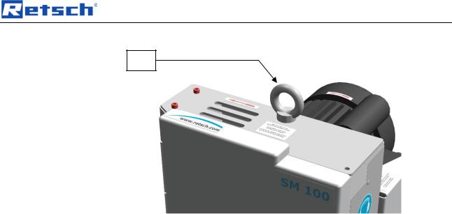
Fig. 2: Removing the transport aid
Only use the transport aid (TH) when lifting the device. The device weighs approx. 73 kg. Select secure lifting equipment that is approved for this weight.
Keep the eyebolt (TH) for transportation at a later date.
The eyebolt must be removed before assembling the hopper.
13
Transport, scope of delivery, installation
3.8Frame assembly

 SQ
SQ
RS |
TR |
|
RS |
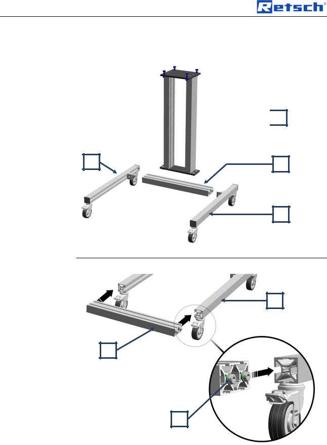
Fig. 3: Components of the stand
The components come pre-assembled to simplify assembly of the frame.
TR |
RS |
TS |
Fig. 4: Assembling the crossbar
•Where necessary slightly loosen the four screws (TS) on the crossbar (TR).
•Slide the crossbar into the lateral guides of the left and right roller track (RS).
14

Transport, scope of delivery, installation
WS |
TR |
SW |
|
WS |
||
|
Fig. 5: Fastening the crossbar angle bracket NB
Ensure that the crossbar (TR) is aligned flush with the pre-assembled angle section (WS).
Tighten the screw on the left and right of the angle section (SW).
Fig. 6: Screwing the crossbar tight
•Tighten the four Allen screws.
15
Loading...