

Page 1
Operating Instructions, Rotor-Beater Mill Model
SR 300
© Retsch GmbH 42781-Haan, Retsch-Allee 1-5, Germany, 2/8/2012 0002
Page 2

Information on these operating instructions
The present operating instructions for the Model SR 300 rotorbeater mill provide all the necessary information on the topics
mentioned in the table of contents.
These instructions will guide the readers to the topics designated
for each target group, essential to safe use of the SR 300 in accordance with the purpose for which the unit is intended. Each
target group should be fully familiar with the relevant chapters,
as this is essential to safe and proper use of the equipment.
The present technical documentation has been designed for use
as both a reference source and learning guide. Each chapter
represents a self-contained unit.
These operating instructions do not contain any information on
repairs. If repairs should ever become necessary, kindly contact
your supplier or the Retsch company.
2/8/2012 Retsch GmbH 2 0002
Page 3

Information on these operating instructions .................... 2
Safety ................................................................................. 4
Safety notes .................................................................................. 4
Warnings ...................................................................................... 5
Repairs .......................................................................................... 5
Confirmation ............................................................................... 5
Technical specifications ................................................... 6
Utilization in accordance with the intended purpose ........... 6
Drive ............................................................................................. 7
Motor rotation speed ................................................................. 7
Rotor-beater rotation speed ...................................................... 7
Rated power................................................................................. 7
Feed grain size ............................................................................. 7
Collection receptacle volumes .................................................. 7
Noise levels .................................................................................. 7
Safety class ................................................................................... 7
Equipment dimensions .............................................................. 7
Equipment weights..................................................................... 7
Footprint ...................................................................................... 7
Shipping and installation .................................................. 8
Packing ......................................................................................... 8
Shipping ....................................................................................... 8
Temperature fluctuations ................................................ 8
Intermediate storage ......................................................... 8
Requirements for the installation site ...................................... 8
Setting up the unit ...................................................................... 9
Electrical connection .................................................................. 9
Operation ........................................................................ 10
Operating elements and their use .......................................... 10
Schematic view of the operating elements: .................... 10
Survey of the operating controls ...................................... 11
Opening and closing the mill housing .................................. 12
Insert 360° sieve frame with ring sieve ................................. 12
Insert 180° grinding insert with frame and sieve insert ..... 13
Starting or stopping the SR 300 ............................................. 13
Filter bag and collection receptacle ....................................... 14
Feed the product to be pulverized ......................................... 14
Mounting a feeder unit ............................................................ 15
Instructions for use ......................................................... 16
General ....................................................................................... 16
Ultimate fineness ...................................................................... 16
Operating principle for the SR 300 ....................................... 16
General ............................................................................ 17
Cleaning ...................................................................................... 17
SR 300 .................................................................................. 17
Sieves, grinding inserts and rotors ............................. 17
Maintenance .............................................................................. 17
Required inspections ................................................................ 17
Accessories ................................................................................ 18
Copyright ................................................................................... 18
Modifications............................................................................. 18
Appendix .................................................. following pages
2/8/2012 Retsch GmbH 3 0002
Page 4

Safety
!
We reject herewith any and all claims in conjunction with personal injury or property damage resulting from failure to observe the following safety instructions.
Target group: Everyone who deals with the machine in any
manner whatsoever.
The SR 300 is a modern, high-performance product manufactured by
the Retsch GmbH. It incorporates the latest technology. The SR 300 is
entirely safe in operation when used for the intended purpose and in
accordance with the present technical documentation.
Safety notes
You, as the owner/operator, must ensure that persons entrusted with
the operation of the SR 300:
have read and understood all the regulations included in the chap-
ter on safety,
have made themselves familiar, prior to starting work, with all the
operating instructions and regulations for the target groups relevant to them,
have complete, immediate and unhindered access to the technical
literature for this machine,
before commencing work, new personnel shall have been made
familiar with safe and appropriate use of the SR 300 before
starting work with the machine, through instruction by a qualified
person and/or with the help of the present technical documentation.
Incorrect operation can result in injuries to persons and damage to
property. You bear responsibility for your own safety and for that of
your coworkers.
Ensure that no unauthorized persons have access to the SR 300.
For your own protection, have your co-workers certify in writing the
fact that they have received instruction in the operation of the SR 300.
A suggestion for a printed form which can be used for this purpose will
be found at the end of the chapter on safety.
2/8/2012 Retsch GmbH 4 0002
Page 5

Warnings
!
Personal injury
Property damage
Local Retsch representative
Your supplier
The Retsch GmbH
_______________________________________________
_______________________________________________
_______________________________________________
_______________________________________________
_______________________________________________
The following symbols are used to identify specific hazard
potentials:
Repairs
These operating instructions do not include any repair instructions. In
the interest of your own safety, have repairs made only by the Retsch
GmbH or an authorized representative (service technician).
In this case, please notify the following:
Your address for service:
Confirmation
I have familiarized myself with the foreword to the operating instruc-
tions and the chapter on safety.
_________________________________________________
Owner/operator signature
_______________________________________________
Service technician's signature
2/8/2012 Retsch GmbH 5 0002
Page 6

Technical specifications
Do not make any modifications to the machine and use only RETSCH
approved spares and accessories.
Failure to comply will invalidate the CE declaration and guarantee.
Chemicals
Coal
Dolomite
Dried fruit
Dried vegetables
Fertilizers
Fly ash
Fodder
Grain
Kaolin
Lime
Peat, dried
Pellets
Pharmaceuticals
Plants
Plaster
Salts
Seed grain
Spices
Synthetic resins
Tobacco
Machine designation: SR 300
Utilization in accordance with the intended purpose
Suitable for applications in which differing product is to be ground and
changes in product are frequent and where it is necessary to open the
door after each cycle to clean the grinding chamber. The SR 300 is not
designed for use as a production machine but rather as a laboratory
unit, engineering for 8-hour.
The SR 300 pulverizes dry, soft to medium-hard materials at hardness
of up to about 4 on the Mohs scale.
It is suitable in particular for pulverizing the materials listed below:
and for many other materials with similar fracture properties.
The ultimate fineness which can be achieved is dependent on the geometry of the sieve openings and the fracture properties of the product
being processed. In the most favorable cases fineness of < 60 µm can
be achieved.
Our applications laboratory is always at your service to provide additional information.
2/8/2012 Retsch GmbH 6 0002
Page 7

Drive
Height appr. 1183
Width appr. 560
Depth appr. 831
With DR 100
Height appr. 1443
Width appr. 560
Depth appr. 831
without DR 100/75
approx. 95 kg net
with DR 100/75
approx. 103 kg net
3-phase motor with brakes
Motor rotation speed
2870 r.p.m. at 50 Hz
3440 r.p.m. at 60 Hz
Rotor-beater rotation speed
approx. 8100 r.p.m. at 50 Hz
approx. 9700 r.p.m. at 60 Hz
Rated power
2200 Watts
Feed grain size
max. 15 mm
When feeding individual items, feed grain size may also be up to
20 mm
Collection receptacle volumes
5.000 ml or
30.000 ml
Noise levels
Noise measurement as per DIN 45635-31-01, Class 3
The noise values will also be influenced by the nature of the product
being ground.
Example:
Noise level LWA = 101 dB(A)
Emission value for worksite L
Operating parameters:
Feed product: Artificial fertilizer, grain size < 3 mm
= 91 dB(A)
pEq
Safety class
IP 54
Equipment dimensions
Equipment weights
Footprint
831 mm x 560 mm; no safety clearances are required!
2/8/2012 Retsch GmbH 7 0002
Page 8
Shipping and installation
Please retain the packaging for the duration of the guarantee period
since, in case a claim arises, your guarantee entitlements will be jeopardized if the unit is returned in unsuitable packaging.
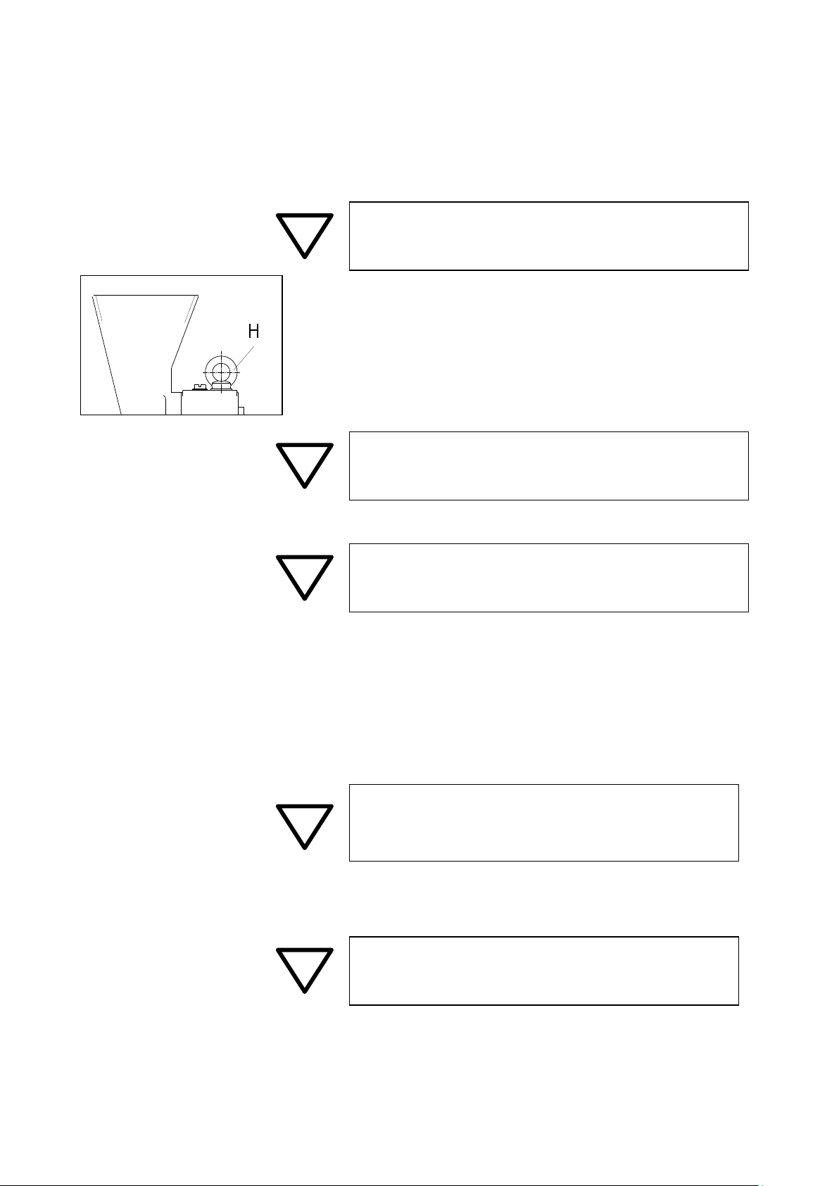
Fig. 1
Shipping
Use the eye bold H whenever you are moving the SR 300. Fig. 1
The SR 300 may not be subjected to impact or vibration during transportation; it must not be thrown. The electronic and mechanical components could otherwise be damaged.
In case of wide temperature fluctuations (during shipment by air, for
instance) the SR 300 will have to be protected against condensation;
the electronic components could otherwise be damaged.
When the ambient temperature exceeds or falls below that specified,
the electronic and mechanical components may be damaged, and performance data changed to an unknown extent.
At higher humidity, the electronic and mechanical components may
be damaged, and performance data changed to an unknown extent.
Target group: Owners, freight forwarders, operators
Packing
The type of packaging used has been selected in accordance with the
shipping mode. It complies with generally accepted packaging guidelines.
Temperature fluctuations
Intermediate storage
Ensure that the SR 300 is also kept in a dry place during intermediate storage.
Requirements for the installation site
Ambient temperature
The ambient temperature should be between 5°C and 40°C.
Humidity
Maximum relative humidity 80% at temperatures up to 31°C;
linear decline down to 50% relative humidity at 40°C.
2/8/2012 Retsch GmbH 8 0002
Page 9

8
9
1
2
3
4
5
6
7
Fig. 2
Installation site – Altitude
max. 2000 m above mean sea level
Setting up the unit
Set up the SR 300 on a solid surface.
In order to bolt the base frame to the floor (maximum 10 mm screw
diameter), it will be necessary to remove the two adjusting screws 6
and the plastic caps 7 at the front. Fig. 2
Electrical connection
The power connection may be made only by a qualified and licensed
electrician.
The voltage and frequency specifications for the SR 300 will be
found on the machine’s data plate.
Ensure that the values shown there correspond to those for the
local power supply.
Use the supplied power cord to connect the SR 300 to the power
network.
The line power cord supplied does not have a plug since the design
of the plug will depend on the installation location and the regulations applicable in the particular country.
When connecting the power cord to the line supply, external fus-
ing shall be provided in accordance with local codes.
Failure to observe the values on the data plate can cause damage to
either the electrical or the mechanical components or both.
It will be necessary to check the direction of rotation (corresponding
to the arrow on the motor housing) before putting the machine into
service for the first time.
If the rotation direction is reversed, grinding will not be satisfactory
and mechanical components could be damaged.
2/8/2012 Retsch GmbH 9 0002
Page 10

Operation
Target group: Operators
Operating elements and their use
Schematic view of the operating elements:
Fig. 3
2/8/2012 Retsch GmbH 10 0002
Page 11

Operating elements and their functions
Item
Element
Illustration
Function
A
Main switch with
rotary knob
Isolates and connects the SR 300 from and with the power supply
ON = SR 300 is switched on
OFF = SR 300 is switched off
B
Door closure
Opens and closes the door for the SR 300, tightens the door gasket.
Press and turn to right = locks the door
Press and turn to left = opens the door
C
Feed hopper on the
door
Serves to feed material but not to keep a reserve of product to be
pulverized.
Positively prevents product from being ejected from the hopper.
D
Filter bag
Previous page
Increases throughput performance and ensures separation of solids
in the air stream.
E
Collection receptacle, 5 liters
Previous page
Accepts the pulverized material.
F
Motor brake release
lever
When the SR 300 is at a standstill and this lever is pressed backwards
the motor brake is released, allowing the rotor-beater to be turned by
hand for cleaning purposes.
G
Shipping screw
Used to lift and move the SR 300 with hoist tackle. It is removed as
soon as any Retsch feeder unit is attached.
H
Adjustment screws
at base frame
Compensate for uneven floors by leveling the SR 300 base frame.
When unscrewed entirely the opening is clear, allowing the base
frame to be anchored to the floor with 10 mm diam. bolts.
Survey of the operating controls
2/8/2012 Retsch GmbH 11 0002
Page 12

Opening and closing the mill housing
Fig. 4
Open the housing only with the SR 300 switched off.
Turn the main switch A to its OFF position. Fig. 4
Press the handwheel B and turn it to the left.
Handwheel will catch in the end position;
the door can now be opened.
Close in reverse order.
Close the door only if the contact surfaces are absolutely free of pulverized product and other foreign objects.
Mechanical components and the gasket could otherwise be
damaged.
!
Do not open the SR 300 with the motor running.
When pulverizing product which is toxic or otherwise hazardous
to health there is a danger of inhaling harmful dusts.
!
Do not open the SR 300 and release the motor brakes simultaneously.
Injury hazard resulting from rotor-beater not being held by the
brake.
Fig. 5
Available as accessories are chrome-plated, stainless steel frames and ring
sieves in a choice of sizes, with Conidur or round holes. Fig. 5
Conidur holes 0.08 / 0.12 / 0.20 / 0.25 / 0.50 /
0.75 / 1.0 / 1.25 / 1.5 / 2.0 mm
Round holes 3.0 / 4.0 / 5.0 / 6.0 / 8.0 / 10.0 mm
Unscrew the screws S2.
Remove the ring R1 and insert the ring sieve SI in the groove NU of
ring R2; when using a sieve with Conidur perforations pay attention to
the arrow, corresponding to the rotor’s direction of rotation.
Carefully position the ring R1 until the sieve SI slides into the groove
NU.
Screw down the screws S2 and tighten them securely.
Open the door.
Insert the sieve frame with the ring sieve; ring R1 is to the front, ring R2
to the rear.
The screw heads S3 at the ring R2 must seat in the holes in the mill
housing.
Close the door.
Check to ensure that a collection receptacle is in place.
Start the SR 300.
Insert 360° sieve frame with ring sieve
2/8/2012 Retsch GmbH 12 0002
Page 13

Insert 180° grinding insert with frame and sieve insert
Fig. 6
Available as accessories are stainless steel grinding sets, with a frame and
sieve inserts, in a choice of sizes, with Conidur or round perforations.
Fig. 6
Conidur holes 0.08 / 0.12 / 0.20 / 0.25 / 0.50 /
0.75 / 1.0 / 1.25 / 1.5 / 2.0 mm
Round holes 3.0 / 4.0 / 5.0 / 6.0 / 8.0 / 10.0 mm
Unscrew the screws S2.
Remove the ring R1 and insert the ring sieve SI in the groove NU of
ring R2.
Carefully position the ring R1 until the sieve SI slides into the groove
NU.
Screw down the screws S2 and tighten them securely.
Open the door.
Insert the sieve frame with the ring sieve; ring R1 is to the front, ring
R2 to the rear.
The screw heads S3 at the ring R2 must seat in the holes in the mill
housing.
Close the door.
Check to ensure that a collection receptacle is in place.
Start the SR 300.
Fig. 7
Die SR 300 is started and stopped with the main switch A. Fig. 7
Insert the sieve frame with the ring sieve or grinding set with sieve
insert.
Close the door.
Attach the collection receptacle.
Starting
Turn the knob at switch A to “ON”.
Stopping
Turn the knob at switch A to “OFF”.
Starting or stopping the SR 300
2/8/2012 Retsch GmbH 13 0002
Page 14

Filter bag and collection receptacle
Fig. 8
Fig. 9
By using a cloth filter bag or a Conidur filter (optional accessory), attached between the SR 300 and the collection receptacle, the air stream
generated by the rotor-beater as it turns will be deflected and routed
downward to the material discharge. In addition, it increases material
throughput and ensures the separation of the fines in the air stream. Fig.
8
Slide the filter bag E over the flange, holding the clamping ring at an
angle.
Tighten the clip E1.
Mount the collection receptacle F.
Tighten the clips F1.
If the receiver is installed without a filter bag then it will be necessary to
expect dust to be discharged from the feed hopper D; therefore never
use the SR 300 without the filter bag or Conidur filter being installed.
Feed the product to be pulverized
Maximum feed grain size should not exceed 15 mm.
To allow for batch-wise or continuous operation the SR 300 can be retrofitted with a 30-liter plastic collection receptacle and a Model DR
100/75 feeder (optional accessories).
Close and switch on the SR 300.
Slowly pour product into the feeder hopper D. Fig. 9
A baffle incorporated into the feeder hopper D keeps product from being ejected from the unit. Fig. 9
Feed product slowly and continuously, and only with the SR 300 running.
Overly large product grains or excessive product volumes can force
the SR 300 to stop; mechanical components could be damaged.
!
During pulverization dust-like product can exit from the feeder hopper,
filter bag or Conidur filter. When dealing with products which are toxic
or otherwise harmful to health, utilize either an extractor hood or personal safety equipment.
Hazard due to inhaling dusts which are dangerous to health.
!
Some products form an explosive mix with air after pulverization. Check
the properties of the product being processed.
Explosion hazard.
2/8/2012 Retsch GmbH 14 0002
Page 15

Mounting a feeder unit
Fig. 10 Fig. 11 Fig. 12
Fig. 13
Prepare the DR 100/75 for use as the feeder, following the operating instructions provided with that unit.
Assembly :
Unscrew the eye bolt H.
Screw in the pin BO.
Attach the DR 100/75 to the holder HA, tightening down the two
screws SC only slightly.
Slide the holder HA with the DR 100/75 onto the pin BO.
Tighten down the knurled screw.
Align the DR 100/75.
Tighten down the two hex-head bolts SC securely.
Connect the DR 100/75 power cord at a grounded power socket.
Please refer to the data plate for the voltage and frequency specifica-
tions for the DR 100/75.
Be absolutely sure to observe the values on the data plate.
Failure to match the values specified on the data plate can result in
damage to electronic and mechanical components.
When feeding larger quantities it is generally advisable to use an automatic feeder unit to meter the product uniformly. This largely avoids
unnecessary loading of the grinding components and reduces heat of
friction which could otherwise arise. The Model DR 100/75 feeder
(optional accessory) is suitable for attaining uniform material feed. Fig.
13
2/8/2012 Retsch GmbH 15 0002
Page 16

Instructions for use
Operating schematic
Pulverization in the SR 300 rotor-beater mill is effected by impact, rebound and shear action.
Once it has been introduced into the feed hopper, the product passes
into the grinding chamber where the size reduction process takes place
between the rotor-beater, the grinding insert and the sieve. See also
the operating schematic.
Once the product has achieved the appropriate ultimate fineness it
passes through the sieve and into the collection receptacle.
Using a cloth filter bag or a Conidur filter (optional accessory) mounted between the SR 300 and the collection receptacle, the air stream
generated by the rotor-beater as it turns will be deflected and routed
downward toward the material discharge. In addition it will increase the
material throughput rate and ensures that the solids portion in the air
stream will be separated out.
Target group: Laboratory personnel
General
The SR 300 is a modern, high-performance product manufactured by
the Retsch GmbH.
A broad selection of accessories makes the SR 300 rotor-beater grinding mill a versatile device suitable for a wide range of applications,
principally in chemicals and pharmaceuticals, in mineralogy and biology, etc., and in industrial and research laboratories.
The SR 300 is used primarily for preliminary and final pulverization of
dry, soft to medium-hard materials of up to about 4 on the Mohs
hardness scale.
Ultimate fineness
The ultimate fineness which can be achieved is dependent on the size
of the sieve openings and the fracture characteristics of the pulverization product. In favorable cases fineness of < 60 µm can be attained.
Operating principle for the SR 300
2/8/2012 Retsch GmbH 16 0002
Page 17

General
Fig. 14
The grinding chamber in the SR 300 can be cleaned with a brush and,
if necessary, an industrial vacuum cleaner and compressed air.
The motor brake can be released to facilitate cleaning the SR 300
grinding chamber; use lever F (Fig. 14) to do so. The rotor-beater can
now be turned easily, thus simplifying 0cleaning.
The SR 300 is engineered to IP 54 safety standards.
!
Never clean the SR 300 with running water.
Hazard of fatal electrical shock.
Dry all wet parts thoroughly after cleaning.
Rust can form on wet components.
Cleaning
SR 300
Sieves, grinding inserts and rotors
Once they have been removed from the SR 300, these items can be
cleaned under running water or in an ultrasonic bath.
Maintenance
The SR 300 is largely maintenance-free.
Required inspections
The limit switches and the motor brakes are to be checked twice a year
for proper operation.
Limit switch on the left, at the door hinge
The limit switch must shut down the motor at a maximum opening
gap of 3 mm.
Limit switch on the right, at the quick-acting catch
The motor brakes must engage when the hand wheel is turned by a
maximum of 45°.
Motor brakes
Start the SR 300.
Stop the SR 300.
2/8/2012 Retsch GmbH 17 0002
Use a stopwatch to time the braking period.
If the braking period should exceed 1.5 seconds, then contact the
authorized service technicians.
Page 18

Accessories
Collection receptacle, 30 liters
Filter bag for the 30-liter collection receptacle
Stand for the DR 100/75 feeder
DR 100/75 automatic feeder unit
Ring filter with Conidur plate for the 5-liter collection receptacle
Dust filter with clamping rings, for ring filter
Grime collector tray, plastic
Sieve frame, 360°, made of chrome-plated steel
Sieve frame, 360°, made of stainless steel
Grinding insert, 180°, made of stainless steel
Ring sieve, 360°, Conidur, from 0.08 to 2.0 mm
Ring sieve, 360°, round holes, from 3.0 to 10 mm
Sieve inserts, 180°, Conidur, from 0.08 to 2.0 mm
Sieve inserts, 180°, round holes, from 3.0 to 10 mm
Copyright
Reproducing or distributing this manual, utilizing or distributing the
contents is permitted only with the express consent of Retsch GmbH.
Non-compliance will subject violators to claims for damages.
Modifications
Subject to technical modification without prior notice.
2/8/2012 Retsch GmbH 18 0002
Page 19

Page 20

Page 21

Authorized person for the compilation of technical documents:
J. Bunke (technical documentation)
The following records are held by Retsch GmbH in the form of Technical Documentation:
Detailed records of engineering development, construction plans, study (analysis) of the measures required for
conformity assurance, analysis of the residual risks involved and operating instructions in due form according to
the approved regulations for preparation of user information data.
The CE-conformity of the Retsch Rotor Beater Mill Type SR 300 is assured herewith.
In case of a modification to the machine not previously agreed with us as well as the use of not licensed spare parts and accessories this certificate will lose its validity.
Retsch GmbH Haan, January 2010
Dr. Stefan Mähler
Manager technical services
R e t s c h G mb H R e t s c h - A l l e e 1 - 5 4 2 7 8 1 H a a n G e r m a n y w w w. r e t s c h . c o m
ROTOR BEATER MILL
SR 300
FB-EW-805-025 (E) Änderungsstand F 01.2012
CERTIFICATE OF CE-CONFORMITY
Translation
Certificate of CE-Conformity according to:
EC Mechanical Engineering Directive 2006/42/EC
Applied harmonized standards, in particular:
DIN EN ISO 12100 Security of machines
EC Directive Electromagnetic Compatibility 2004/108/EC
Applied standards, in particular:
DIN EN 50081 Generic standard interference emission - living areas - in conjunction with
EN 55022 and EN 60555
DIN EN 50082 Generic standard interference resistance - living areas
Additional applied standards, in particular
DIN EN 61010 Safety prescriptions concerning measuring-, operating-, controlling- and
laboratory equipment
Page 22

Page 23

Page 24

Copyright
® Copyright by
Retsch GmbH
Haan, Retsch-Allee 1-5
D-42781 Haan
Federal Republic of Germany
 Loading...