

Page 1
Operating Instructions for Rotor Bea te r M i l l Type SR 200
© Retsch GmbH 42781-Haan, Retsch-Allee 1-5, Germany, 2/8/2012 0002
Page 2

Guide to Operating Instructions
The present operating instructions for the rotor beater mill of
the type SR 200 give all the information necessary for the areas
indicated in the table of contents. They give instructions to the
target group(s) defined for the respective areas on how to
handle the SR 200 in a safe and proper fashion. Knowledge of
the relevant chapters is, for the respective target group(s), a
prerequisite for safe and proper handling. The present technical
documentation is a work of reference and a training manual.
Each of the individual chapters is an independent unit. These
operating instructions do not include any repair instructions. In
the case of any necessary repairs, please contact your supplier or
Retsch GmbH directly.
2/8/2012 Retsch GmbH 2 0002
Page 3

Guide to Operating Instructions .................................................... 2
Safety .............................................................................................. 4
Safety instructions .................................................................................... 4
Warning signs ............................................................................................ 5
Repairs ........................................................................................................ 5
Confirmation ............................................................................................. 5
Technical Data ............................................................................... 6
Application in the case of proper use .................................................... 6
Drive ........................................................................................................... 7
Speed .......................................................................................................... 7
Rated power .............................................................................................. 7
Feed grain size ........................................................................................... 7
Volume of collecting pan ........................................................................ 7
Noise data .................................................................................................. 7
Type of protection .................................................................................... 7
Unit dimensions ........................................................................................ 7
Unit weights .............................................................................................. 7
Required standing area ............................................................................. 7
Dimensions Sheet ........................................................................... 8
Transport and setting up ................................................................ 9
Packing ....................................................................................................... 9
Transport ................................................................................................... 9
Temperature fluctuations ......................................................... 9
Intermediate storage .................................................................. 9
Parameters for setting-up location ......................................................... 9
Setting up with underframe ..................................................................... 9
Setting up on the laboratory table .......................................................... 11
Electrical connection ............................................................................... 11
Operation ....................................................................................... 12
Operating elements and operation ......................................................... 12
Graphic view of the operating elements: ................................... 12
Overview of operating elements.................................................. 13
Opening and closing of mill housing ..................................................... 14
Insert sieve frame 360° with ring sieve ................................................. 14
Insert grinding insert 180° with frame and sieve insert ...................... 15
Start or stop the SR 200 ........................................................................... 15
Filter hose and collecting pan ................................................................. 16
Feed material to be crushed .................................................................... 16
Assembly of feed device .......................................................................... 17
Working Instructions..................................................................... 18
General ....................................................................................................... 18
End fineness .............................................................................................. 18
The SR 200's mode of working .............................................................. 18
General ........................................................................................... 19
Cleaning ..................................................................................................... 19
SR 200 ............................................................................................. 19
Sieves, grinding inserts and rotor ........................................... 19
Maintenance .............................................................................................. 19
Necessary inspections .............................................................................. 19
Accessories ................................................................................................ 20
Copyright ................................................................................................... 20
Changes ...................................................................................................... 20
Appendix ............................................................... following pages
2/8/2012 Retsch GmbH 3 0002
Page 4

Safety
!
We exclude any claims for compensation for material damage and
personal injury caused by non-observance of the following safety
instructions.
Target group: All persons concerned in any way with the machine.
The SR 200 is a highly modern, efficient product from Retsch
GmbH. It is state of the art. If the user handles the machine in a
proper fashion and with knowledge of the technical
documentation present here, it is completely safe operationally.
Safety instructions
You, as the operator, must ensure that the persons instructed to work
with the SR 200:
have noted and understood all the regulations for the safety area,
know all instructions for what action to take as well as the regulations
of the relevant target groups before work is commenced,
have access to the technical documentation at all times and without
problem,
that new personnel is familiarised before commencement of work on
the SR 200 with the safe and proper handling either by a verbal
introduction from a competent person and/or by means of the
present technical documentation.
Improper operation can result in personal injury and damage to
property. You are responsible for your own safety and that of your
personnel.
Ensure that no unauthorised persons have access to the SR 200.
For your own protection, make sure that you are given
confirmation that your personnel have received instruction in
the use of the SR 200. You will find a draft of a related form
after the chapter on safety.
2/8/2012 Retsch GmbH 4 0002
Page 5

Warning signs
!
Personal injury
Material damage
the Retsch agency in your country
your supplier
Retsch GmbH directly
___________________________________________
___________________________________________
___________________________________________
___________________________________________
___________________________________________
We give warnings using the following symbols:
Repairs
These operating instructions do not include any repair instructions. For
your own safety, repairs may only be carried out by Retsch GmbH or an
authorised agent (service technicians).
Should the need arise, please notify:
Your service address:
Confirmation
I have noted the foreword and the chapter on safety.
____________________________________________
Operator's signature
____________________________________________
Service technician's signature
2/8/2012 Retsch GmbH 5 0002
Page 6

Technical Data
Do not make any modifications to the machine and use only RETSCH
approved spares and accessories.
Failure to comply will invalidate the CE declaration and guarantee.
Chemicals
Fertiliser
Drugs
Dolomite
Flue ash
Fruit
Animal feed
Gypsum
Vegetables
Corn
Spices
Artificial
resins
Limestone
Kaolin
Potassium salts
Coal
Pellets
Plants
Seeds
Salts
Tobacco
Peat
Cellulose
Machine type designation: SR 200
Application in the case of proper use
For uses where very frequently different materials have to be ground
and it is necessary to open the door to clean the grinding chamber after
every grinding operation.
The SR 200 is not designed as a production machine, but as a
laboratory unit, meant for 8-hour single-shift operation.
The SR 200 crushes dry, soft to medium-hard materials with a hardness
of up to about 4 according to Mohs.
It is especially suitable for the materials listed below:
and many other, similar materials.
The achievable end fineness depends on the hold width of the sieve
and the crushing properties of the material to be ground. In favourable
cases it is possible to achieve finenesses of < 60 µm.
For further information, please contact our application laboratory.
2/8/2012 Retsch GmbH 6 0002
Page 7

Drive
Height approx.560
Width approx.420
Depth approx.445
with underframe
Height approx..1183
Width approx.560
Depth approx.700
with underframe and DR 100
Height approx.1443
Width approx.560
Depth approx.700
SR 200
net approx. 35kg
with underframe
net approx. 57kg
with underframe and DR 100
net approx. 65kg
1-phase AC motor with brake or
Three-phase current motor with brake
Speed
2850min-1 at 50Hz
3420min-1 at 60Hz
Rated power
1100 Watt
Feed grain size
max. 15mm
With single-piece feed also up to 20mm
Volume of collecting pan
5,000 ml or
30,000ml
Noise data
Noise measurement according to DIN 45635-31-01-KL3
Noise data are dependent on the fracturing properties fo the
product beeing ground.
Example:
Sound power level: LWA = 86 dB(A)
Workplace-related emission L
= 81 dB(A)
pAeq
Operating conditions:
Ring sieve : 0,5mm
Sample material: rye, grain size up to 15 mm
Filling ratio of grinding chamber: feeding quantity each until
motor rated power is reached.
Type of protection
IP 54
Unit dimensions
Unit weights
Required standing area
(700 mm x 560 mm; no safety distances necessary!)
2/8/2012 Retsch GmbH 7 0002
Page 8
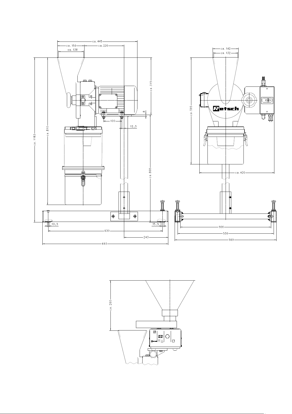
Dimensions Sheet
0 I
with DR 100/75
2/8/2012 Retsch GmbH 8 0002
Page 9

Transport and setting up
Please keep the packing for the whole of the guarantee period. If,
in the case of a complaint, the unit is returned in inadequate
packing, your guarantee rights may be jeopardised.
Fig.1
Transport
To transport the SR 200 use the ring bolt H. Fig.1
The SR 200 may not be subjected to shocks, shaken or thrown
during transport. Otherwise the electrical and mechanical
components may be damaged.
In the case of major temperature fluctuations (e.g. with
transportation by air), the SR 200 must be protected against
condensation. Otherwise the electrical components may be
damaged.
When the ambient temperature exceeds or falls below that specified,
the electronic and mechanical components may be damaged, and
performance data changed to an unknown extent.
At higher humidity, the electronic and mechanical components may
be damaged, and performance data changed to an unknown extent.
Target group: Operators, Forwarders, Users
Packing
The packing is adjusted to the transport route. It complies with
the generally applicable packing regulations.
Temperature fluctuations
Intermediate storage
Ensure that the SR 200 is also kept dry when subject to
intermediate storage.
Parameters for setting-up location
Ambient temperature
The ambient temperature should be between 5°C and 40°C.
Relative humidity
Maximum relative humidity 80 % at temperatures of 31°C, falling in a
linear fashion to 50 % relative humidity at 40°C.
Setting-up altitude
max. 2000 m above sea level
2/8/2012 Retsch GmbH 9 0002
Setting up with underframe
Page 10

8
9
1
2
3
4
5
6
7
Fig.2
Fig.3
We recommend that the SR 200 be mounted on an
underframe, which can be supplied as an accessory. Fig.2
Mounting:
* Connect centre cross-piece 9 base side pieces 8 using the
cylinder-head screws 1
* Push covering caps 2 onto the projecting thread
* Place stand tube 3 in the sleeve 4 and fasten tight with the
headless screws 5
* If necessary, the underframe can be aligned using the
cylinder-head screws 6
So as to be able to fasten the underframe with screws,
maximum diam. 10mm possible, to the ground, the two setting
screws 6 and the front plastic caps 7 must be removed.
* Place SR 200 on the underframe Fig.3
* To fasten hexagon-head bolts SCH M8x35 supplied with
the underframe, use spring washers and hexagon nuts
2/8/2012 Retsch GmbH 10 0002
Page 11

Setting up on the laboratory table
Fig.4
You can also mount the SR 200 on your laboratory table. Fig.4
* Measure thickness of laboratory table. The thickness
should not be less than 30mm to ensure that safe working
with the SR 200 is not adversely affected.
* Use screws with a max. diam. of 8mm and a length of
laboratory table thickness + 25mm
* Stand the SR 200 on the table
* Draw holes for the table using the holes present in the
motor of the SR 200
The distance from the holes to the front edge of the table
must be such that it is possible without difficulty to mount and
dismount the collecting pan or the filter hose.
Electrical connection
The electrical connection may only be made by an electrician.
* The voltage and frequency of the SR 200 can be found on the nameplate.
* Ensure that the values agree with the applicable power
supply.
* Connect the SR 200 to the power supply using the
connection cable supplied.
The power cable supplied does not have a plug because the
type of plug depends on the setting-up location and the
relevant regulations in the country concerned
* When connecting the power cable to the power supply,
provide an external fuse in accordance with the regulations
of the setting-up location.
If the values on the nameplate are not observed, electronic and
mechanical components may be damaged.
Before operating for the first time, the direction of rotation must be
checked, see rotation arrow on the motor.
If the direction of rotation is incorrect the grinding will be inadequate
and mechanical parts may be damaged.
2/8/2012 Retsch GmbH 11 0002
Page 12

Operation
0 I
Target group: Users
Operating elements and operation
Graphic view of the operating elements:
Fig.5
2/8/2012 Retsch GmbH 12 0002
Page 13

Operating elements and their function
Item
Element
Figure
Function
A
Power switch with
ON/OFF button
0 I
Isolates and connects the SR 200 from/with the power supply
I depressed = SR 200 is switched on
0 depressed = SR 200 is switched off
A1
Power switch with
knob
Isolates and connects the SR 200 from/with the power supply
ON = SR 200 is switched on
OFF = SR 200 is switched off
B
Door lock
Opens and closes the door of the SR 200, clamps the door seal
Depressed and turned clockwise = locks the door
Depressed and turned anticlockwise = opens the door
D
Feed funnel at door
Takes the material to be crushed, but is not used to store this
material.
Reliably prevents the material to be crushed from splashing back.
E
Filter hose
Page 15
Prevents build-up of the air pressure generated by the rotating rotor
and thus accelerates material throughput.
F
5l collecting pan
Page 15
Takes the crushed material.
G
Release lever for
motor brake
When pressed to the rear, facilitates release of the motor brake and
thus makes it possible to rotate the rotor manually for cleaning
purposes.
H
Transport screw
Prevents damage to mechanical and electrical components during
transport.
I
Setting screws on
underframe
Make it possible to align the underframe when the floor is not even.
When screwed out, they expose the openings with which it is
possible to fasten the underframe to the floor, diam. 10mm
Overview of operating elements
2/8/2012 Retsch GmbH 13 0002
Page 14

Opening and closing of mill housing
0 I
Fig.6
Only open when the SR 200 is switched off.
* Press button 0 on power switch A or, with A1, turn to OFF
position Fig.6
* Press hand wheel B and turn in anticlockwise direction
* Hand wheel locks into end position
* the door can be opened
* close in reverse order
Only close the door when the contact surfaces are absolutely free of
material to be crushed or other contaminants.
Mechanical components and the seal may be damaged.
!
Do not open the SR 200 when motor is running.
When crushing toxic or otherwise health-endangering materials,
there is a danger that health-hazardous dust may be inhaled.
!
Do not open the SR 200 and release the motor brake at the same time.
Danger of injury from unbraked rotor.
Fig.7
A selection of sieve frames which are chromium-plated, of stainless
steel and ring sieves of stainless steel with Conidur or round
perforations are available as accessories. Fig.7
Conidur 0.08/0.12/0.20/0.25/0.50/
0.75/1.0/1.25/1.5/2.0mm
Round hole 3.0/4.0/5.0/6.0/8.0/10.0mm
* Undo screws S2
* Remove ring R1 and insert sieve SI in the groove NU of the ring
R2
* Carefully mount the ring R1 until the sieve SI slides in the
groove NU
* Turn in screws S2 and tighten well
* Open door
* Insert sieve frame with ring sieve, ring R1 is to the front and ring
R2 to the rear
* Screw heads S3 on the ring R2 belong to the holes of the mill
housing
* Close door
Ensure that a collecting pan is mounted.
* Start the SR 200
Insert sieve frame 360° with ring sieve
2/8/2012 Retsch GmbH 14 0002
Page 15

Insert grinding insert 180° with frame and sieve insert
Fig.8
A selection of grinding inserts with frames and sieve inserts of
stainless steel with Conidur or round perforations are available as
accessories. Fig.8
Conidur 0.08/0.12/0.20/0.25/0.50/
0.75/1.0/1.25/1.5/2.0mm
Round hole 3.0/4.0/5.0/6.0/8.0/10.0mm
* Undo screws S2
* Remove ring R1 and insert sieve SI in the groove NU of the
ring R2
* Carefully mount the ring R1 until the sieve SI slides in the
groove NU
* Turn in screws S2 and tighten well
* Open door
* Insert sieve frame with ring sieve, ring R1 is to the front and
ring R2 to the rear
* Insert sieve frame with ring sieve, ring R1 is to the front and
ring R2 to the rear
* Screw heads S3 on the ring R2 belong to the holes of the mill
housing
* Close door
Ensure that a collecting pan is mounted.
* Start the SR 200
0 I
Fig.9
The SR 200 is started or stopped at the power switch A or A1.
Fig.9
* Insert sieve frame or grinding insert
* Close door
* Mount collecting pan
Start
* Press button “I“ on switch A or turn knob on switch A1
to “ON“
Stop
* Press button “0“ on switch A or turn knob on switch A1
“OFF“
Start or stop the SR 200
2/8/2012 Retsch GmbH 15 0002
Page 16

Filter hose and collecting pan
Fig.10
Fig.11
With the use of a cloth filter hose or a Conidur filter, available as
an accessory, between the SR 200 and the collecting pan, the air
stream caused by the rotating rotor is taken off and conveyed
downward to the material discharge. Furthermore, it accelerates
the material throughput and ensures a gentle crushing process.
Fig.10
* Push filter hose E over the flange while holding the clamping
clip at an angle.
* Clamp the lock E1
* Hang in the collecting pan F
* Clamp the locks F1
If the collecting pan is mounted without a filter hose, it can be
expected that dust will escape from the feed funnel D, and so you
should never operate the SR 200 without a filter hose or Conidur
filter.
Feed material to be crushed
The maximum feed grain size should not exceed 15mm.
For batch or continuous operation, the SR 200 can be retrofitted
with a 30l plastic collecting receptacle and a feed device of the
type DR 100/75, which are available as accessories.
* Close the SR 200 and switch on
* Slowly feed the material to be crushed into the feed funnel D
Fig.11
The rebound safeguard installed in the feed funnel D prevents the
feed material from bouncing back. Fig.11
Only feed the material to be crushed into the feed funnel slowly and
continuously with the SR 200 running.
The material to be crushed or excessive feed quantity can bring the
SR 200 to a standstill and this may damage mechanical
components.
!
During crushing, material in dust form may escape from the feed funnel.
In the case of toxic or otherwise health-hazardous materials, use an
extraction device.
Danger from inhalation of health-hazardous dust.
!
Many materials form explosive air mixtures. Check the properties of the
material you are crushing.
Explosion hazard!
2/8/2012 Retsch GmbH 16 0002
Page 17

Assembly of feed device
Fig.12 Fig.13 Fig. 14
Fig.15
Prepare the DR 100/75 for feed operation in accordance with its
operating instructions.
Assembly :
* Undo ring screw H, Fig.12
* Turn in bolts BO, Fig.13
* Push on fixture HA with tommy screw, Fig. 14
* Tighten tommy screw
* Mount DR 100/75 and align
* Fasten with the two hexagon-head screws SC
M6x20 DIN933, Fig. 14
* Insert power cable of the DR 100/75 in a socket with
earthing
* You will find the voltage and frequency of the DR100/75 on
the nameplate
If the values on the nameplate are not observed, electronic and
mechanical components may be damaged.
When feeding larger quantities, it is advisable in general to feed
the material to be crushed evenly using a feed device. This
largely prevents any unnecessary load on the grinding tools and
reduces possible friction heat. An appropriate means of ensuring
even material feed is use of the feed device of the type DR
100/75, which is available as an accessory. Fig.15
2/8/2012 Retsch GmbH 17 0002
Page 18

Working Instructions
General sketch
Material is crushed in the SR 200 rotor beater mill by impact,
bouncing and shearing action.
After the material has been fed into the feed funnel, it passes
into the grinding chamber, where the crushing process takes
place between the rotor, the grinding insert and the sieve. see
also general sketch
As soon as the material has reached the relevant end fineness, it
passes the sieve and into the collecting pan.
The use of a cloth filter hose or a Conidur filter, available as an
accessory, which can be fixed between the SR 200 and the
collecting pan, prevents build-up of the air stream generated by
the rotating rotor and partly accelerates the material throughput.
This ensures a gentle crushing process.
Target group: Laboratory personnel
General
The SR 200 is highly modern, high-performance product from
Retsch GmbH.
In view of the wide range of accessories available, the SR 200
rotor beater mill is a unit with many varied uses in the chemical
and pharmaceutical sectors, mineralogy and biology etc. in
industrial and research laboratories.
The SR 200 is used mainly for precrushing and fine crushing of
dry, soft to medium-hard materials with a hardness of up to
approximately 4 according to Mohs.
End fineness
the achievable end fineness depends on the hole width of the
sieve and the crushing properties of the material. In favourable
cases it is possible to achieve finenesses of < 60 µm.
The SR 200's mode of working
2/8/2012 Retsch GmbH 18 0002
Page 19

General
Fig.16
The SR 200 can be cleaned with brushes, paintbrushes and
possibly an industrial vacuum cleaner, as well as compressed air.
To clean the grinding chamber on the SR 200 the motor brake
can be released at the lever G ( Fig.16 ). the rotor is now easy to
turn and this facilitates cleaning.
The SR 200's type of protection is IP54.
!
Do not clean the SR 200 under running water.
Danger of fatal electric shock
Dry all wet parts well after cleaning.
Flash rust or deposited rust may form.
Cleaning
SR 200
Sieves, grinding inserts and rotor
Can be cleaned under running water once they have been
removed from the SR 200.
Maintenance
The SR 200 largely maintenance-free.
Necessary inspections
Every six months the limit switches and the motor brake must
be checked with regard to their serviceability.
Limit switch to the left on the door hinge
* With an opening gap of 3mm max, the limit switch must
shut down the motor
Limit switch to the right on the quick-acting closure
* When the handwheel is turned a maximum of 45°, the
motor brake must be activated.
Motor brake
* Start the SR 200
* Stop the SR 200
* Measure the braking time using a stopwatch
* Should the braking time exceed 0.5 seconds, contact the
service technicians
2/8/2012 Retsch GmbH 19 0002
Page 20

Accessories
* Underframe
* 30l collecting pan
* Filter hose for 30l vessel
* Stand for feed device DR 100/75
* Feed device DR 100/75
* Ring filter with Conidur plate for 5l vessel
* Dust filter with clamping rings for ring filter
* Dirt collection tray of plastic
* 360° sieve frame of chromium-plated steel
* 360° sieve frame of stainless steel
* 180° grinding insert of stainless steel
* 360° ring sieves, Conidur from 0.08 to 2.0 mm
* 360° ring sieves, round hole from 3.0 to 10 mm
* 180° sieve inserts, Conidur from 0.08 to 2.0 mm
* 180° sieve inserts, round hole from 3.0 to 10mm
Copyright
This documentation may only be passed on or duplicated and its
content used or passed on with the express permission of Retsch
GmbH. Any violation will be liable for compensation.
Changes
We reserve the right to make technical changes.
2/8/2012 Retsch GmbH 20 0002
Page 21

Authorized person for the compilation of technical documents:
J. Bunke (technical documentation)
The following records are held by Retsch GmbH in the form of Technical Documentation:
Detailed records of engineering development, construction plans, study (analysis) of the measures required for
conformity assurance, analysis of the residual risks involved and operating instructions in due form according to
the approved regulations for preparation of user information data.
The CE-conformity of the Retsch Rotor Beater Mill Type SR 200 is assured herewith.
In case of a modification to the machine not previously agreed with us as well as the use of not
licensed spare parts and accessories this certificate will lose its validity.
Retsch GmbH Haan, January 2010
Dr. Stefan Mähler
Manager technical services
R e t s c h G m b H R e t s c h -Al l e e 1 - 5 4 2 7 8 1 H a a n G e r m a n y w ww . r e t s c h . c o m
ROTOR BEATER MILL
SR 200
FB-EW-805-019 (E) Änderungsstand G 01.2012
CERTIFICATE OF CE-CONFORMITY
Translation
Certificate of CE-Conformity according to:
EC Mechanical Engineering Directive 2006/42/EC
Applied harmonized standards, in particular:
DIN EN ISO 12100 Security of machines
EC Directive Electromagnetic Compatibility 2004/108/EC
Applied standards, in particular:
DIN EN 50081 Generic standard interference emission - living areas - in conjunction with
EN 55022 and EN 60555
DIN EN 50082 Generic standard interference resistance - living areas
Additional applied standards, in particular
DIN EN 61010 Safety prescriptions concerning measuring-, operating-, controlling- and
laboratory equipment
Page 22

Page 23

Page 24

Copyright
® Copyright by
Retsch GmbH
Haan, Retsch-Allee 1-5
D-42781 Haan
Federal Republic of Germany
 Loading...