

Page 1
Manual
Cutting Mill SM200
Translation
© Retsch GmbH, 42781 Haan, Retsch-Allee 1-5, Germany 06.03.2013 0005
Page 2

Copyright
© Copyright by
Retsch GmbH
Haan, Retsch-Allee 1-5
D-42781 Haan
Federal Republic of Germany
2
Page 3

1 Notes on the Operating Manual ............................................................................................................ 5
1.1 Explanations of the safety warnings .................................................................................................. 6
1.2 General safety instructions ................................................................................................................ 7
1.3 Repairs ............................................................................................................................................... 8
2 Confirmation ........................................................................................................................................... 9
3 Transport, scope of delivery, installation .......................................................................................... 10
3.1 Packaging ........................................................................................................................................ 10
3.2 Transport.......................................................................................................................................... 10
3.3 Temperature fluctuations and condensed water ............................................................................. 10
3.4 Conditions for the place of installation ............................................................................................. 10
3.5 Electrical connection ........................................................................................................................ 11
3.6 Type plate description ...................................................................................................................... 11
3.7 Removing Transport Safeguards ..................................................................................................... 12
3.8 Mounting the Feed Hopper .............................................................................................................. 12
3.8.1 Removing the Transport Safeguard ............................................................................................ 13
3.8.2 Mounting the Feed Hopper .......................................................................................................... 13
3.9 Installation of the machine ............................................................................................................... 14
4 Technical data ....................................................................................................................................... 16
4.1 Use of the machine for the intended purpose.................................................................................. 16
4.2 Emissions......................................................................................................................................... 17
4.3 Degree of protection ........................................................................................................................ 17
4.4 Motor rotation speed ........................................................................................................................ 18
4.5 Receptacle volume .......................................................................................................................... 18
4.6 Rated power .................................................................................................................................... 18
4.7 Dimensions and weight .................................................................................................................... 18
4.8 Required floor space ........................................................................................................................ 18
5 Operating the machine ........................................................................................................................ 19
5.1 Views of the Instrument ................................................................................................................... 19
5.2 Overview table of the parts of the device ........................................................................................ 22
5.3 Operating elements and displays .................................................................................................... 23
5.4 Overview Table of the Operating Elements and the Display ........................................................... 23
5.5 Opening and closing of the grinding chamber ................................................................................. 24
5.6 Mounting the bottom sieve ............................................................................................................... 24
5.7 Replacing the rotor .......................................................................................................................... 24
5.7.1 Removing the Rotor ..................................................................................................................... 25
5.7.2 Inserting the Rotor ....................................................................................................................... 25
5.8 Inserting the filter unit and collecting receptacle.............................................................................. 26
5.9 Starting the grinding process ........................................................................................................... 26
3
Page 4

5.10 Stopping the grinding process ......................................................................................................... 27
6 Mode of Operation of Feed Hopper .................................................................................................... 28
7 Assembling and using the cyclone .................................................................................................... 29
7.1 Cyclone assembly ............................................................................................................................ 29
7.1.1 Inserting the wide mouth bottle adapter ...................................................................................... 33
8 Cleaning and service ........................................................................................................................... 34
8.1 Adjusting the cutting bars ................................................................................................................ 34
9 Fault messages ..................................................................................................................................... 37
10 Disposal ................................................................................................................................................. 38
11 Index ...................................................................................................................................................... 39
Appendix ............................................................................................................................... following pages
4
Page 5

Notes on the Operating Manual
Pos: 1.1 /00005 Überschriften/1. Übersc hriften/1 Hinweise zur Bedienungsanleitung @ 0\mod_1222347415287_9.doc @ 2 631 @ 1 @ 1
1 Notes on the Operating Manual
Pos: 1.2 /00010 Bedienungsanleitungen Kapitelsammlungen/CryoMill/0001 Hinweis e zur Bedienungsanleitung/Modul Hinweis zur Bedienungsanleitung @ 0\mod_ 1222347341773_9.doc @ 2540 @ @ 1
This operating manual is a technical guide on how to operate the device safely and
it contains all the information required for the areas specified in the table of
contents. This technical documentation is a reference and instruction manual. The
individual chapters are complete in themselves.
Familiarity (of the respective target groups defined according to area) with the
relevant chapters is a precondition for the safe and appropriate use of the device.
This operating manual does not contain any repair instructions. If faults arise or
repairs are necessary, please contact your supplier or get in touch with Retsch
GmbH directly.
Application technology information relating to samples to be processed is not
included but can be read on the Internet on the respective device’s page at
Pos: 1.3 /00010 Bedienungsanleitungen Kapitelsammlungen/CryoMill/0001 Hinweis e zur Bedienungsanleitung/Modul Änder ungen @ 0\mod_1222347341241_9.doc @ 2526 @ @ 1
www.retsch.com.
Changes
Pos: 1.4 /00010 Bedienungsanleitungen Kapitelsammlungen/CryoMill/0001 Hinweis e zur Bedienungsanleitung/Modul Urheberre cht @ 0\mod_1222347342038_9.d oc @ 2547 @ @ 1
Subject to technical changes.
Pos: 2.1 /00010 Bedienungsanleitungen Kapitelsammlungen/------- Seitenumbruch ----------- @ 0\mod_1222344373758_ 0.doc @ 2386 @ @ 1
Copyright
Disclosure or reproduction of this documentation, use and disclosure of its contents
are only permitted with the express permission of Retsch GmbH.
Infringements will result in damage compensation liability.
5
Page 6
Notes on the Operating Manual
WARNING
Type of danger / personal injury
Source of danger
– Possible consequences if the dangers are not observed.
• Instructions on how the dangers are to be avoided.
WARNING
CAUTION
Type of danger / personal injury
Source of danger
– Possible consequences if the dangers are not observed.
• Instructions on how the dangers are to be avoided.
CAUTION
NOTICE
Nature of the property damage
Source of property damage
– Possible consequences if the instructions are not observed.
• Instructions on how the dangers are to be avoided.
Pos: 2.2 /00005 Überschriften/1.1 Überschrif ten/1.1 Überschriften BDA/11 Erklärunge n zu den Sicherheitswarnungen @ 0\ mod_1222344569771_9.doc @ 2484 @ 2 @ 1
1.1 Explanations of the safety warnings
Pos: 2.3 /00003 Standard Kapitel/General Modul Warnhinweise Erklärung neu @ 0\mod_1234858329746_9.doc @ 6190 @ @ 1
In this Operating Manual we give you the following safety warnings
Serious injury may result from failing to heed these safety warnings. We give you
the following warnings and corresponding content.
We also use the following signal word box in the text or in the instructions on action
to be taken:
Moderate or mild injury may result from failing to heed these safety warnings.
We give you the following warnings and corresponding content.
Pos: 2.4 /00010 Bedienungsanleitungen Kapitelsammlungen/------- Seitenumbruch ----------- @ 0\mod_1222344373758_ 0.doc @ 2386 @ @ 1
We also use the following signal word box in the text or in the instructions on action
to be taken:
In the event of possible property damage we inform you with the word
“Instructions” and the corresponding content.
We also use the following signal word in the text or in the instructions on action to
be taken:
NOTICE
6
Page 7
Notes on the Operating Manual
CAUTION
Read the Operating Manual
Non-observance of these operating instructions
– The non-observance of these operating instructions can
result in personal injuries.
• Read the operating manual before using the device.
• We use the adjacent symbol to draw attention to the
necessity of knowing the contents of this operating
manual.
CAUTION
Changes to the machine
– Changes to the machine may lead to personal injury.
• Do not make any change to the machine and use spare parts and
accessories that have been approved by Retsch exclusively.
NOTICE
Changes to the machine
– The conformity declared by Retsch with the European Directives will lose
its validity.
– You lose all warranty claims.
• Do not make any change to the machine and use spare parts and
accessories that have been approved by Retsch exclusively.
Pos: 2.5 /00005 Überschriften/1.1 Überschrif ten/1.1 Überschriften BDA/11 Gener elle Sicherheitshinweise @ 0\mod_122 2344568974_9.doc @ 2463 @ @ 1
1.2 General safety instructions
Pos: 2.6 /00004 Warnhinweise/V0002 VORS ICHT Bedienungsanleitung lesen @ 2\ mod_1263894982815_9.doc @ 1863 0 @ @ 1
Pos: 2.7 /00003 Standard Kapitel/General Modul Zielgruppe und Sicherheit @ 0 \mod_1228722955300_9.doc @ 4100 @ @ 1
Target group : All persons concerned with the machine in any form
This machine is a modern, high performance product from Retsch GmbH and
complies with the state of the art. Operational safety is given if the machine is
handled for the intended purpose and attention is given to this technical
Pos: 2.8 /00003 Standard Kapitel/General Modul Sicherheitshinweise @ 0\mod_ 1228722954800_9.doc @ 4086 @ @ 1
Pos: 2.9 /00004 Warnhinweise/V0015 VORS ICHT + HINWEIS Sach- und Person enschäden @ 1\mod_1236238456676_9 .doc @ 7642 @ @ 1
documentation.
You, as the owner/managing operator of the machine, must ensure that the people
entrusted with working on the machine:
• have noted and understood all the regulations regarding safety,
• are familiar before starting work with all the operating instructions and
specifications for the target group relevant for them,
• have easy access always to the technical documentation for this machine,
• and that new personnel before starting work on the machine are familiarised
with the safe handling of the machine and its use for its intended purpose,
either by verbal instructions from a competent person and/or by means of
this technical documentation.
Improper operation can result in personal injuries and material damage. You are
responsible for your own safety and that of your employees.
Make sure that no unauthorised person has access to the machine.
Pos: 2.10 /00010 Bedienungsanleitungen K apitelsammlungen/------- Seitenumbruch ----------- @ 0\mod_1222344373758 _0.doc @ 2386 @ @ 1
7
Page 8

Notes on the Operating Manual
The Retsch representative in your country
Your supplier
Retsch GmbH directly
Pos: 2.11 /00005 Überschriften/1.1 Übersc hriften/1.1 Überschriften BDA/11 Reparat uren @ 0\mod_1223624336511_9.doc @ 2978 @ @ 1
Reperaturen
1.3 Repairs
Pos: 2.12 /00003 Standard Kapitel/Gen eral Modul Reparaturen @ 0\mod_1228 722954535_9.doc @ 4079 @ @ 1
This operating manual does not contain any repair instructions. For your own
safety, repairs may only be carried out by Retsch GmbH or an authorized
representative or by Retsch service engineers.
In that case please inform:
Your Service Address:
Pos: 3.1 /00020 BDA Software/20005 PM GC Kapitelsammlung/- - - - Seitenum bruch - - - - @ 0\mod_1208857688413_0.doc @ 337 @ @ 1
8
Page 9

Confirmation
I have read and taken note of the contents of all chapters in this operating
manual as well as all safety instructions and warnings.
User
Surname, first name (block letters)
Position in the company
Signature
Service technician or operator
Surname, first name (block letters)
Position in the company
Place, date and signature
Pos: 3.2 /0010 BDA Software/Überschrift en/1. Überschriften/1 Bestätigung (Formular für den Betreiber) @ 0\mod_12088708 41095_9.doc @ 430 @ 1 @ 1
Bestätigung
2 Confirmation
Pos: 3.3 /00003 Standard Kapitel/General Modul Bestätigung @ 0\mod_122872 2962707_9.doc @ 4114 @ @ 1
This operating manual contains essential instructions for operating and maintaining
the device which must be strictly observed. It is essential that they be read by the
operator and by the qualified staff responsible for the device before the device is
commissioned. This operating manual must be available and accessible at the
place of use at all times.
The user of the device herewith confirms to the managing operator (owner) that
(s)he has received sufficient instructions about the operation and maintenance of
the system. The user has received the operating manual, has read and taken note
of its contents and consequently has all the information required for safe operation
and is sufficiently familiar with the device.
As the owner/managing operator you should for your own protection have your
employees confirm that they have received the instructions about the operation of
the machine.
Pos: 4 /00010 Bedienungsanleitungen Ka pitelsammlungen/------- Seitenumbruch ----------- @ 0\mod_1222344373758_0. doc @ 2386 @ @ 1
9
Page 10

Transport, scope of delivery, installation
NOTICE
Storage of packaging
– In the event of a complaint or return, your warranty claims may be
endangered if the packaging is inadequate or the machine has not been
secured correctly.
• Please keep the packaging for the duration of the warranty period.
NOTICE
Transport
– Mechanical or electronic components may be damaged.
• The machine may not be knocked, shaken or thrown during
transport.
NOTICE
Temperature fluctuations
The machine may be subject to strong temperature fluctuations during transport
(e.g. aircraft transport)
– The resultant condensed water may damage electronic components.
• Protect the machine from condensed water.
NOTICE
Ambient temperature
– Electronic and mechanical components may be damaged and the
performance data alter to an unknown extent.
• Do not exceed or fall below the permitted temperature range of the
machine (5°C to 40°C / ambient temperature).
Pos: 5.1 /00005 Überschriften/1. Überschri ften/1 Verpackung, Transport und Aufst ellung @ 0\mod_1226494451893_9.doc @ 3380 @ 1 @ 1
3 Transport, scope of delivery, installation
Pos: 5.2 /00005 Überschriften/1.1 Überschrif ten/1.1 Überschriften BDA/11 Verpacku ng @ 0\mod_1226495088973_9.doc @ 3392 @ 2 @ 1
3.1 Packaging
Pos: 5.3 /00003 Standard Kapitel/General Modul Verpackung @ 0\mod_12289 84618355_9.doc @ 4892 @ @ 1
Pos: 5.4 /00004 Warnhinweise/H0001 H INWEIS Aufbewahrung der Verpackung @ 0\mod_1228918881595_9.doc @ 475 3 @ @ 1
Pos: 5.5 /00005 Überschriften/1.1 Überschrif ten/1.1 Überschriften BDA/11 Transp ort @ 0\mod_1226495164391_9.doc @ 3398 @ 2 @ 1
3.2 Transport
Pos: 5.6 /00004 Warnhinweise/H0017 H INWEIS Transport @ 0\mod_122891888 3019_9.doc @ 4802 @ @ 1
The packaging has been adapted to the mode of transport. It complies with the
generally applicable packaging guidelines.
Pos: 5.7 /00005 Überschriften/1.1 Überschrif ten/1.1 Überschriften BDA/11 Temperatursc hwankungen @ 0\mod_1226495 190738_9.doc @ 3404 @ 2 @ 1
3.3 Temperature fluctuations and condensed water
Pos: 5.8 /00004 Warnhinweise/H0016 H INWEIS Temperaturschwankungen @ 0\ mod_1233564121287_9.doc @ 5570 @ @ 1
Pos: 5.9 /00005 Überschriften/1.1 Überschrif ten/1.1 Überschriften BDA/11 Beding ungen für den Aufstellort @ 0\mod_12 26497029322_9.doc @ 3428 @ 2 @ 1
3.4 Conditions for the place of installation
Pos: 5.10 /00003 Standard Kapitel/Gen eral Modul Umgebungstemperatur 5°C - 40°C @ 0\mod_1228918538881_9.doc @ 4745 @ @ 1
Pos: 5.11 /00004 Warnhinweise/H0021 HIN WEIS Umgebungstemperatur 5°C bis 4 0°C @ 0\mod_1228918883441_9.doc @ 4816 @ @ 1
Pos: 5.12 /00003 Standard Kapitel/Gen eral Modul Luftfeuchtigkeit @ 0\mod_122 8918538693_9.doc @ 4738 @ @ 1
Atmospheric humidity:
Maximum relative humidity 80% at temperatures up to 31°C, decreasing linearly up
Pos: 5.13 /00004 Warnhinweise/H0011 HIN WEIS Luftfeuchtigkeit @ 0\mod_12 28918882628_9.doc @ 4788 @ @ 1
10
to 50% relative humidity at 40°C
Page 11

Transport, scope of delivery, installation
NOTICE
Atmospheric humidity
– Electronic and mechanical components may be damaged and the
performance data alter to an unknown extent.
• Do not exceed the admissible range for atmospheric humidity.
WARNING
NOTICE
Electrical connection
– Mechanical or electronic components may be damaged.
• Please observe the information on the type plate.
1 2 3 4 5 6 7 8 9
10
11
12
14
13
Pos: 5.14 /00005 Überschriften/1.1 Übersc hriften/1.1 Überschriften BDA/11 Elektrisc her Anschluss @ 0\mod_122656506 7445_9.doc @ 3500 @ 2 @ 1
3.5 Electrical connection
Pos: 5.15 /00003 Standard Kapitel/Gen eral Modul Elektrischer Anschluss @ 0\ mod_1228918538521_9.doc @ 4731 @ @ 1
When connecting the power cable to the mains supply, use an external fusethat
complies with the regulations applicable to the place of installation .
• Please check the type plate for details on the necessary voltage and
frequency for the device.
• Make sure the levels agree with the existing mains power supply.
• Use the supplied connection cable to connect the device to the mains power
Pos: 5.16 /00004 Warnhinweise/H0008 HIN WEIS Elektrischer Anschluss @ 0\ mod_1228918882424_9.doc @ 4781 @ @ 1
supply.
Pos: 5.17.1 /00005 Überschriften/1.1 Ü berschriften/1.1 Überschriften BDA/11 Type nschild Beschreibung @ 3\mod_128093 3953941_9.doc @ 22302 @ 2 @ 1
3.6 Type plate description
Pos: 5.17.2 /00003 Standard Kapitel/Gen eral Modul Typenschild @ 3\mod_1280 931092443_9.doc @ 22278 @ @ 1
Fig. 1: Type plate lettering
1 Device designation
2 Year of production
3 Part number
4 Serial number
5 Manufacturer’s address
11
Page 12
Transport, scope of delivery, installation
WARNING
1.W0004
Risk of injury to skin and hands
Fast rotating cutting blade
– There is a risk of injuring hands, fingers and skin.
• Never operate the device without a feed hopper.
TH
6 CE marking
7 Disposal label
8 Bar code
9 Power version
10 Mains frequency
11 Capacity
12 Amperage
13 Number of fuses
14 Fuse type and fuse strength
In the case of questions please provide the device designation (1) or the part
Pos: 5.18 /00005 Überschriften/1.1 Übersc hriften/1.1 Überschriften BDA/11 Trans porthilfe entfernen @ 0\mod_12290766 73566_9.doc @ 5020 @ 2 @ 1
number (3) and the serial number (4) of the device.
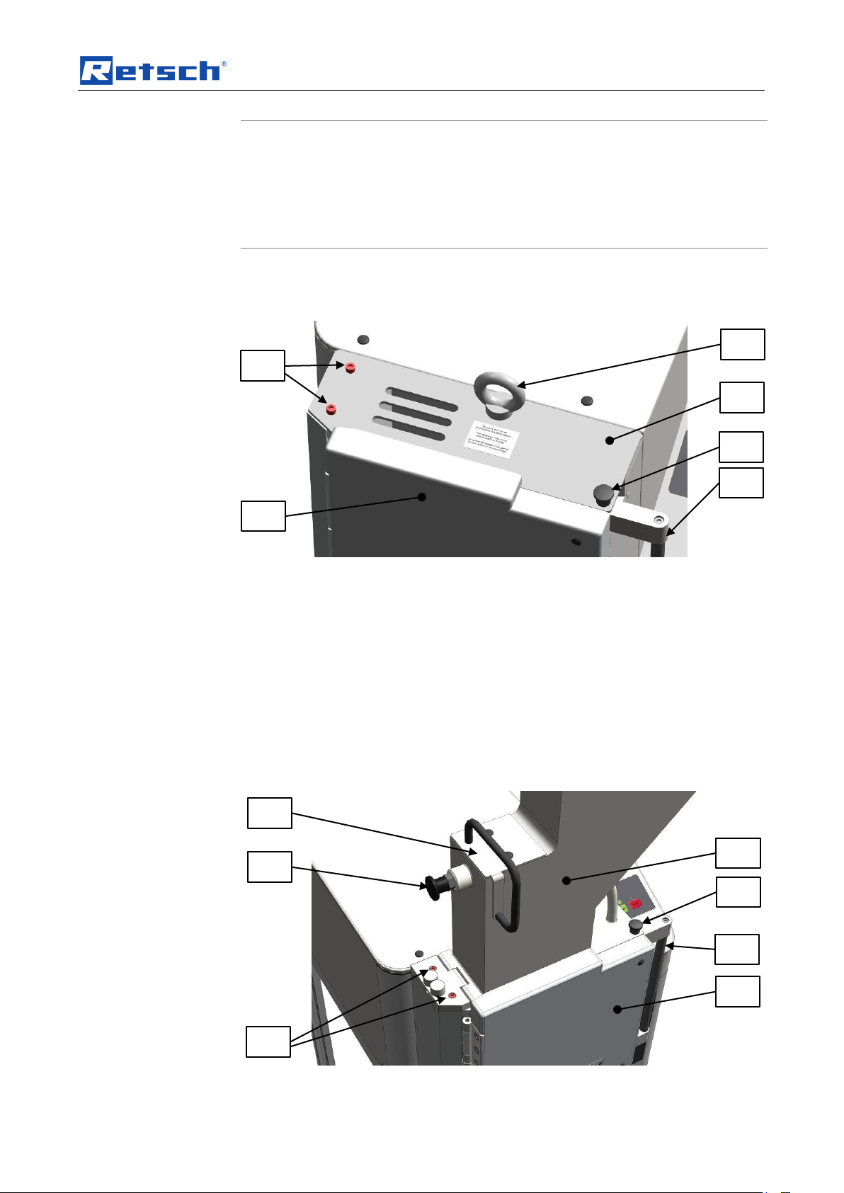
3.7 Removing Transport Safeguards
Pos: 5.19 /00010 Bedienungsanleitungen K apitelsammlungen/SM200/0010 SM2 00 Transport, Lieferumfang und Aufstellen/10 10 SM200 Modul Transporthilfe entfer nen @ 3\mod_1280230245196_9.doc @ 22007 @ @ 1
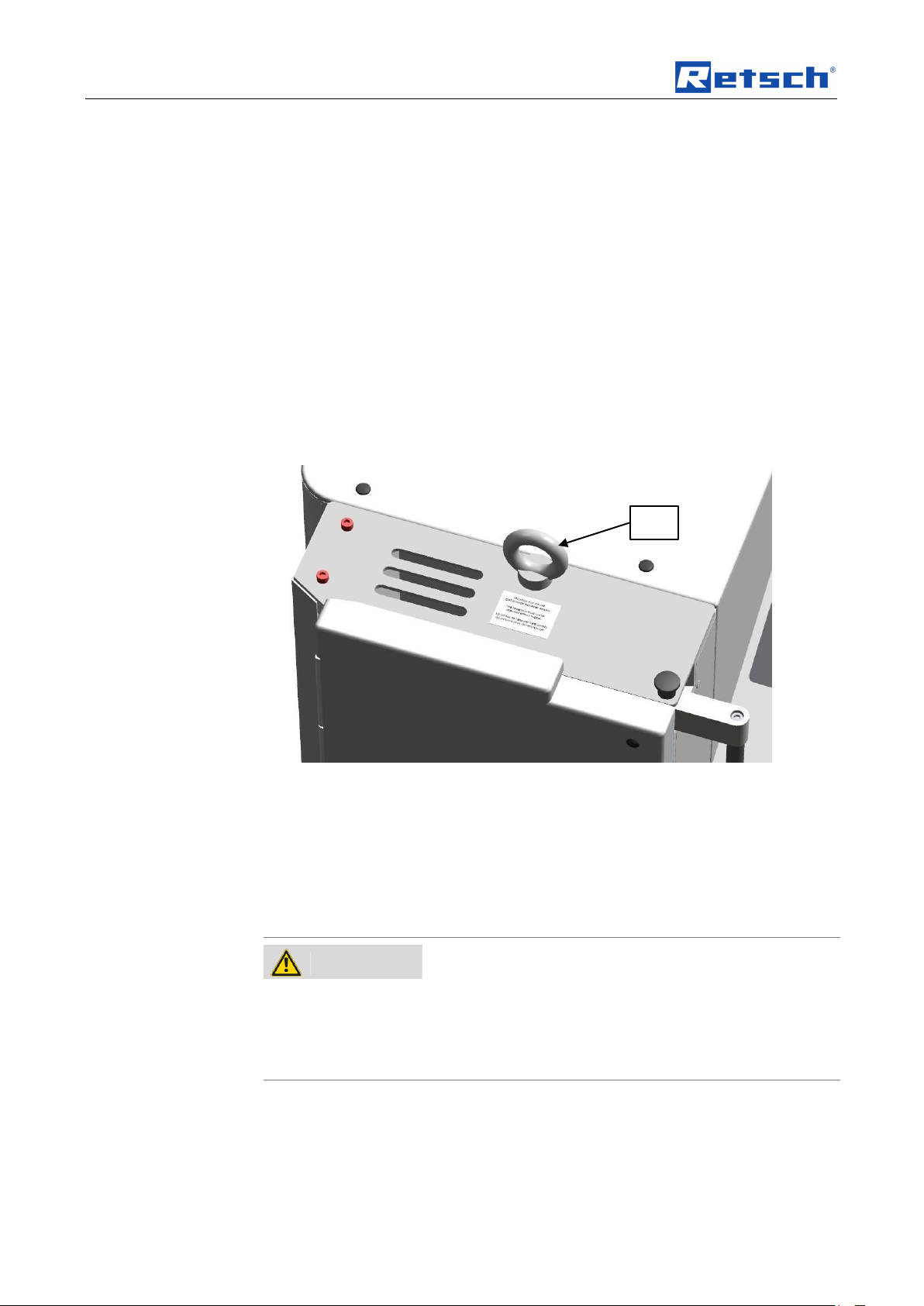
Fig. 2: Removing the transport aid
Lift the device only by the transport aid (TH). The weight of the device is approx. 90
kg. Choose a safe lifting sling that is approved for this weight.
Keep the eye bolt(TH) for transport again at a later date.
Pos: 5.20 /00005 Überschriften/1.1 Ü berschriften/1.1 Überschriften BDA/11 Mont age des Einfülltrichters @ 2\mod_1258 709491283_9.doc @ 17540 @ @ 1
The eye bolt must be removed before the hopper is assembled.
3.8 Mounting the Feed Hopper
Pos: 5.21 /00004 Warnhinweise/W0004 WARNUNG schnell rotierende Messer @ 3\ mod_1280230540628_9.doc @ 2203 4 @ @ 1
Pos: 5.22 /00004 Warnhinweise/H0019 HIN WEIS Transportsicherung SM300 @ 0\ mod_1228918883206_9.doc @ 4809 @ @ 1
12
Page 13
Transport, scope of delivery, installation
NOTICE
Transport safeguard
– Components may be damaged.
• Operate the machine only without the transport safeguard or
transport the machine only with transport safeguard.
E
F S T
B R D
TH E F
TS S T
Pos: 5.23 /00005 Überschriften/1.1.1 Ü berschriften/111 Transportsicherung entfern en @ 2\mod_1258709630300_9.doc @ 17547 @ @ 1
3.8.1 Removing the Transport Safeguard
Pos: 5.24 /00010 Bedienungsanleitungen K apitelsammlungen/SM200/0010 SM2 00 Transport, Lieferumfang und Aufstellen/1 015 SM200 Modul Transportsicherung e ntfernen @ 3\mod_1280230246258_9.d oc @ 22016 @ @ 1
Fig. 3: Removing the transport aid
• Remove the transport aid (TH).
• Unlock the grinding chamber door, by pulling the mini detent pin (E) upwards
and pressing the handle of the door latch (F) backwards.
• Open the grinding chamber door (T).
• Remove the two locking screws (S).
NOTE
Pos: 5.25 /00005 Überschriften/1.1.1 Ü berschriften/111 Einfülltrichter montieren @ 2 \mod_1258709690814_9.doc @ 1755 4 @ @ 1
Keep the transport safeguard (TS) for transport at a later date.
3.8.2 Mounting the Feed Hopper
Pos: 5.26 /00010 Bedienungsanleitungen K apitelsammlungen/SM200/0010 SM2 00 Transport, Lieferumfang und Aufstellen/10 05 SM200 Modul Einfülltrichter monti eren @ 3\mod_1280230243258_9.doc @ 21989 @ @ 1
Fig. 4: Mounting the feed hopper
13
Page 14
Transport, scope of delivery, installation
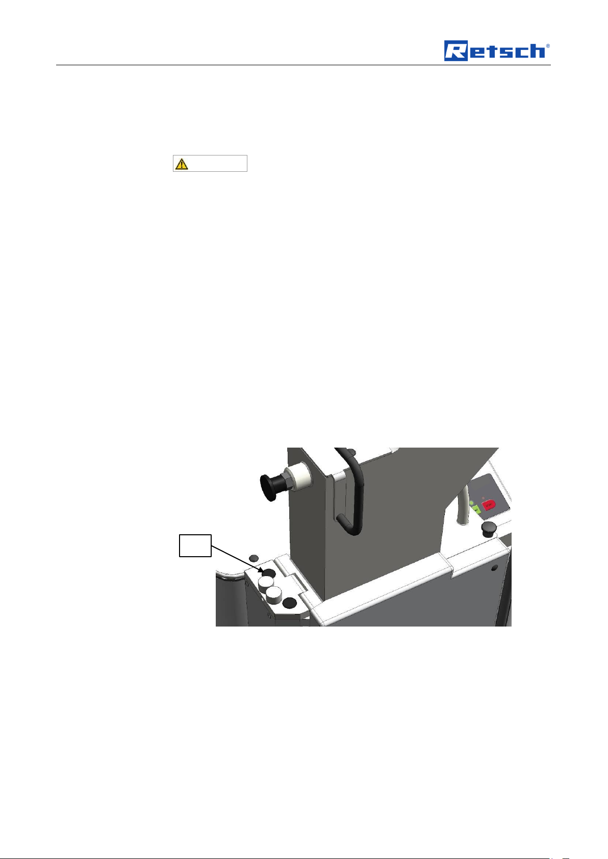
CAUTION
S
• Push the handle of the door latch (F) backwards.
• Open the grinding chamber door (T).
• Pull the plunger (B) into the upper latching position.
• Place the feed hopper (R) on the device. (see diagram)
Until the feed hopper (R) is secured by two socket-head screws, there is a risk of it
falling out of the device.
• Release the detent pin bolt (D) on the plunger (B).
• Push the plunger downwards.
• Screw the two provided socket-head screws (S) through the hinge on the
feed hopper into the enclosure.
• At first, tighten the screws only slightly.
• Close the grinding chamber door.
• Pull the handle on the door latch (F) forwards until the mini detent pin (E)
engages.
• Adjust the feed hopper until the plunger can be moved upwards and
downwards easily without jamming.
• Tighten the two socket-head screws securely. (10 Nm)
• Check again if the plunger moves upwards and downwards easily without
jamming.
• Put the two protective caps (SK) onto the screws (S).
Fig. 5: Putting on the protective caps
NOTE
When new, the grinding chamber door and the handle on the door latch are
Pos: 5.27 /00005 Überschriften/1.1 Übersc hriften/1.1 Überschriften BDA/11 Aufstell en des Gerätes @ 0\mod_12264988 49756_9.doc @ 3464 @ 2 @ 1
somewhat difficult to move.
3.9 Installation of the machine
Pos: 5.28 /00003 Standard Kapitel/Gen eral Modul Aufstellungshöhe @ 0\mod_ 1228918538349_9.doc @ 4724 @ @ 1
Pos: 5.29 /00004 Warnhinweise/H0004 HIN WEIS Boden Aufstellen Vibrationen Bod en @ 0\mod_1228918882236_9.doc @ 4774 @ @ 1
14
Installation height: maximum 2000 m above sea level
Page 15

NOTE
Installation
– Depending on the operating status of the mill, there may be slight
vibrations.
• Place the mill on an even, flat and balanced supporting surface only.
The supporting surface must be stable and must not vibrate.
NOTICE
Installation of the machine
– It must be possible to disconnet the machine from the mains at any time.
• Install the machine such that the connection for the mains cable is
easily accessible.
Pos: 5.30 /00004 Warnhinweise/H0002 HIN WEIS Aufstellung Zugang Gerätestec kdose @ 0\mod_1233836960983_9.doc @ 5820 @ @ 1
Pos: 6.1 /00010 Bedienungsanleitungen Kapitelsammlungen/------- Seitenumbruch ----------- @ 0\mod_1222344373758_ 0.doc @ 2386 @ @ 1
Transport, scope of delivery, installation
15
Page 16

Technical data
Pos: 6.2 /00005 Überschriften/1. Überschri ften/1 Technische Daten @ 0\mod_12 22344525522_9.doc @ 2407 @ 1 @ 1
4 Technical data
Pos: 6.3 /00005 Überschriften/1.1 Überschri ften/1.1 Überschriften BDA/11 Einsatz der Maschine bei bestimmungsgemäß er Verwendung @ 0\mod_122647673224 8_9.doc @ 3243 @ 2 @ 1
4.1 Use of the machine for the intended purpose
Pos: 6.4 /00010 Bedienungsanleitungen Kapitelsammlungen/SM200/0005 SM20 0 Technische Daten/0535 SM200 Modul Zielgru ppe Maschinentyp @ 3\mod_12802 28992457_9.doc @ 21909 @ @ 1
Target group: Owners/managing operators, operators
Pos: 6.5 /00010 Bedienungsanleitungen Kapitelsammlungen/SM200/0005 SM20 0 Technische Daten/0530 SM200 Modul Eins atz bei bestimmungsgemäßer Verwen dung @ 3\mod_1280228985254_9.doc @ 21900 @ @ 1
Machine type designation: SM 200
This heavy-duty cutting mill serves to grind flexible, hard-ductile and fibrous
products and product mixtures in batches or continuously. It is fundamentally not
designed for grinding wet or moist materials. The special shape of the cutting tools
in conjunction with the drive enables a fast, efficient grinding without adversely
affecting the material to be ground.
Special features
The new heavy-duty cutting mill is convincing in difficult size reduction tasks where
other cutting mills fail. The device allows a particularly effective preliminary size
reduction of heterogeneous material mixes, such as waste or electronic
components. Analytical fineness is usually attained in one step. The cutting mill is
used successfully for a great variety of other materials also, whereby the sample
material is only heated to a very low temperature and so the mill is also suitable for
grinding temperature-sensitive materials.
16
Page 17

Technical data
NOTICE
Area of use of the machine
– This machine is a laboratory machine designed for 8-hour single-shift
operation.
• This machine may not be used as a production machine nor is it
intended for continuous operation.
CAUTION
Damage to hearing
The level of noise can be high depending on the type of material,
the knife used, the speed set and the duration of the grinding
process.
- Noise that is excessive in terms of level and duration can cause
impaired or permanently damaged hearing.
• Ensure suitable sound-proofing measures or wear
hearing protection.
The large selection of sieves, hoppers and collecting vessels allow adaptations to
individual tasks.
- fast, gradual size reduction by 18 cutting plates arranged in a helical pattern
along the circumference of the rotor
- parallel section rotor
- cutting tools made of high-quality materials
- high level of operating convenience due to central lock and operator panel
- consistent operational reliability in all user-relevant equipment components
- versatility in use due to a variety of devices and a large number of
accessories
- powerful size reduction owing to a high-torque 2.2-KW motor
- optimised cutting effect by double-acting cutting bars
- very fast cleaning thanks to hinged enclosure with smooth surfaces and
push-fit rotor
Pos: 6.6 /00004 Warnhinweise/H0007 H INWEIS Einsatzbereich des Gerätes 8 Stü ndiger @ 1\mod_1236240219096_9.doc @ 7693 @ @ 1
Pos: 6.7 /00005 Überschriften/1.1 Überschrif ten/1.1 Überschriften BDA/11 Emmisio nen @ 0\mod_1226487095021_9.doc @ 3310 @ @ 1
4.2 Emissions
Pos: 6.8 /00004 Warnhinweise/V0044 VORS ICHT Gehörschaden (GM300, SM2 00, SM300) @ 1\mod_1248181519795_9.d oc @ 11731 @ @ 1
- defined final fineness due to bottom sieves with aperture sizes 0.25 - 20 mm
Pos: 6.9 /00010 Bedienungsanleitungen Kapitelsammlungen/SM200/0005 SM20 0 Technische Daten/0515 SM200 Modul Emmisi onen @ 3\mod_1280228993332_9. doc @ 21918 @ @ 1
Noise measurementin accordance with DIN 45635-31-01-KL3.
Immission at 1-m spacing:
- approx. 66 dB (A) at idle speed
During size reduction, depending on the sample material:
Pos: 6.10 /00005 Überschriften/1.1 Übersc hriften/1.1 Überschriften BDA/11 Sch utzart @ 0\mod_1226491839164_9.doc @ 3328 @ @ 1
- approx. 75 to 92 dB (A) with peaks of up to 98 dB
4.3 Degree of protection
Pos: 6.11 /00010 Bedienungsanleitungen K apitelsammlungen/SM200/0005 SM2 00 Technische Daten/0510 SM200 Modul Sc hutzart @ 3\mod_1280228994332_9.d oc @ 21927 @ @ 1
Pos: 6.12 /00005 Überschriften/1.1 Übersc hriften/1.1 Überschriften BDA/11 Motor drehzahl @ 1\mod_1241508280705_9.d oc @ 8763 @ @ 1
– IP54
17
Page 18

Technical data
4.4 Motor rotation speed
Pos: 6.13 /00010 Bedienungsanleitungen K apitelsammlungen/SM200/0005 SM2 00 Technische Daten/0545 SM200 Modul Mot ordrehzahl @ 3\mod_1280228999 050_9.doc @ 21972 @ @ 1
Pos: 6.14 /00005 Überschriften/1.1 Übersc hriften/1.1 Überschriften BDA/11 Aufnah mevolumen @ 1\mod_1241508533945 _9.doc @ 8777 @ @ 1
The rated speed of the motoris 1500 rpm.
4.5 Receptacle volume
Pos: 6.15 /00010 Bedienungsanleitung en Kapitelsammlungen/SM200/0005 SM2 00 Technische Daten/0540 SM200 Aufnah mevolumen @ 3\mod_1280228997925_ 9.doc @ 21963 @ @ 1
Pos: 6.16 /00005 Überschriften/1.1 Übersc hriften/1.1 Überschriften BDA/11 Nennleist ung @ 0\mod_1226491873164_9.doc @ 3334 @ @ 1
The receptacle volumeis < 5 l and is expandable by accessories to up to 26 l.
4.6 Rated power
Pos: 6.17 /00010 Bedienungsanleitungen K apitelsammlungen/SM200/0005 SM2 00 Technische Daten/0505 SM200 Modul Nennleistung @ 3\mod_1280228995207 _9.doc @ 21936 @ @ 1
Pos: 6.18 /00005 Überschriften/1.1 Übersc hriften/1.1 Überschriften BDA/11 Abmessu ngen und Gewicht @ 0\mod_122649 2212173_9.doc @ 3352 @ @ 1
– 2200 W
4.7 Dimensions and weight
Pos: 6.19 /00010 Bedienungsanleitungen K apitelsammlungen/SM200/0005 SM2 00 Technische Daten/0520 SM200 Modul A bmessungen und Gewicht @ 3\mod_1 280228996082_9.doc @ 21945 @ @ 1
In closed state: (with standard hopper)
Height: 1675mm
Width: 576mm (1090 mm with open hopper)
Depth: 760mm
Weight: approx. 120kg
Weight without rotor and without hopper: approx. 90kg
Pos: 6.20 /00005 Überschriften/1.1 Übersc hriften/1.1 Überschriften BDA/11 Erforderli che Standfläche @ 0\mod_122649 2678414_9.doc @ 3364 @ 2 @ 1
Fig. 6: Dimensions
4.8 Required floor space
Pos: 6.21 /00010 Bedienungsanleitungen K apitelsammlungen/SM200/0005 SM2 00 Technische Daten/0525 SM200 Modul Erf orderliche Standfläche @ 3\mod_1280 228997003_9.doc @ 21954 @ @ 1
Pos: 7 /00010 Bedienungsanleitungen Ka pitelsammlungen/------- Seitenumbruch ----------- @ 0\mod_1222344373758_ 0.doc @ 2386 @ @ 1
18
1090 mm x 760 mm – no safety gaps necessary
Page 19

Operating the machine
G A F C B
K J H I D
E
T
Pos: 8.1 /00005 Überschriften/1. Überschri ften/1 Bedienung des Gerätes @ 0\m od_1226565880211_9.doc @ 3519 @ 1 @ 1
5 Operating the machine
Pos: 8.2 /00005 Überschriften/1.1 Überschrif ten/1.1 Überschriften BDA/11 Ansicht en des Gerätes @ 0\mod_122899058 1782_9.doc @ 4966 @ 2 @ 1
5.1 Views of the Instrument
Pos: 8.3 /00010 Bedienungsanleitungen Kapitelsammlungen/SM200/0015 SM20 0 Bedienung/1535 SM200 Modul Grafische A nsichten des Gerätes @ 3\mod_12 80230780875_9.doc @ 22097 @ @ 1
Fig. 7: Front view
19
Page 20

Operating the machine
E F D
B
L M S
Fig. 8: Front view from the left (detail)
Fig. 9: Rear view
20
Page 21

Operating the machine
B P P I P
O
Fig. 10: View of the grinding chamber
Pos: 8.4 /00010 Bedienungsanleitungen Kapitelsammlungen/------- Seitenumbruch ----------- @ 0\mod_1222344373758_ 0.doc @ 2386 @ @ 1
21
Page 22

Operating the machine
Element
Description
Function
A
Feed hopper access barrier
Prevents people reaching into the feed hopper
B
Plunger
When pulled, it releases the material feed chute.
Pushes sample onto the rotor.
C
Metering plunger
Pushes the material to be ground into the feed hopper
area of the filling plunger
– Pulled out: the material can be fed.
– Pushed in: the material remains in the area of
the filling plunger.
D
Detent pin
Prevents the filling plunger being pulled out, blocks it or
releases it.
– Pulled out: allows the filling plunger to move
freely
– Released: filling plunger latches in the top
position
E
Mini detent pin
Locks the door latch
F
Handle for door latch
Allows the door to be opened
G
Control panel
Starting and stopping the device, setting the speed
H
Parallel section rotor
Size reduction tool
I
Bottom sieve
The size and type of its perforation influences the
fineness of the material being comminuted
J
Ring filter
Air outlet and sieve for sample material
K
Collecting receptacle
Collects comminuted stock
L
ON/OFF switch (main switch)
Connecting and disconnecting the device to/from the
power grid.
- ON = LED (red) STOP lights up
- OFF = all LEDs are off
M
Connection cable
Power connection
O
Rotor shaft
Accommodates the size reduction tool
P
Cutting bars
Counterpart for the size reduction tool
R
Feed hopper
For feeding the sample material
S
Fastening screws for feed hopper
Locking screws for the feed hopper
T
Grinding chamber door
Closes the grinding chamber
Pos: 8.5 /00005 Überschriften/1.1 Überschrif ten/1.1 Überschriften BDA/11 Übersichts tabelle der Geräteteile @ 0\mod_1 228990616846_9.doc @ 4972 @ @ 1
5.2 Overview table of the parts of the device
Pos: 8.6 /00010 Bedienungsanleitungen Kapitelsammlungen/SM200/0015 SM20 0 Bedienung/1570 SM200 Modul Tabelle der Geräteteile @ 3\mod_1280230790859 _9.doc @ 22160 @ @ 1
Pos: 8.7 /00010 Bedienungsanleitungen Kapitelsammlungen/------- Seitenumbruch ----------- @ 0\mod_1222344373758_ 0.doc @ 2386 @ @ 1
22
Page 23

Operating the machine
Element
Description
Function
G1
Start button
Starts the device
G6
Stop button
Stops the device
G4
Green LED
Device is on
G5
Red LED
Device ready for use/flashing light indicates an error
G1
G4
G5
G6
Pos: 8.8 /00005 Überschriften/1.1 Überschrif ten/1.1 Überschriften BDA/11 Grafisch e Ansichten der Bedienelemente und der A nzeige @ 0\mod_1226566362336_9. doc @ 3537 @ @ 1
5.3 Operating elements and displays
Pos: 8.9 /00010 Bedienungsanleitungen Kapitelsammlungen/SM200/0015 SM20 0 Bedienung/1530 SM200 Modul Grafische A nsichten der Bedienelemente und Anz eige @ 3\mod_1280230780000_9.doc @ 22088 @ @ 1
Pos: 8.10 /00005 Überschriften/1.1 Übersc hriften/1.1 Überschriften BDA/11 Übersic htstabelle der Bedienelemente und der Anzeige @ 0\mod_1228990697273_9.doc @ 4978 @ @ 1
Fig. 11: View of the control panel and the display
5.4 Overview Table of the Operating Elements and the Display
Pos: 8.11 /00010 Bedienungsanleitungen K apitelsammlungen/SM200/0015 SM2 00 Bedienung/1571 SM200 Modul Tabelle des Bedienfeldes @ 3\mod_1282553251 540_9.doc @ 22330 @ @ 1
Pos: 8.12 /00010 Bedienungsanleitungen K apitelsammlungen/------- Seitenumbruch ----------- @ 0\mod_1222344373758 _0.doc @ 2386 @ @ 1
23
Page 24

Operating the machine
CAUTION
Injuries in the form of cuts
Sharp cutting edges on the rotors and cutting bars
– The sharp cutting edges on the rotors and cutting bars can injure hands.
• Wear protective gloves when replacing the cutting rotors and
cleaning the grinding chamber.
• Use the rotor extraction tool when handling the cutting rotors.
E
G6
F
Pos: 8.13 /00005 Überschriften/1.1 Übersc hriften/1.1 Überschriften BDA/11 Öffnen und schließen des Gerätes @ 1\mod_1 241510544133_9.doc @ 8826 @ 2 @ 1
5.5 Opening and closing of the grinding chamber
Pos: 8.14 /00010 Bedienungsanleitungen K apitelsammlungen/SM200/0015 SM2 00 Bedienung/1560 SM200 Modul Öffnen und schließen des Gerätes @ 3\mod_ 1280230784234_9.doc @ 22142 @ @ 1
The motor must come to a complete stop before the mill housing can be opened.
• Stop the device by pressing the stop button (G6).
• Pull the mini detent pin (E) upwards
• Press the handle on the door latch (F) backwards.
• Open the grinding chamber door.
NOTE
Do not close the grinding chamber door if the feed hopper is folded out to
the side, because this would damage the device.
Pos: 8.15 /00005 Überschriften/1.1 Übersc hriften/1.1 Überschriften BDA/11 Einsetz en der Bodensiebe @ 1\mod_1241510 694791_9.doc @ 8840 @ @ 1
Fig. 12: Opening the grinding chamber door
5.6 Mounting the bottom sieve
Pos: 8.16 /00010 Bedienungsanleitungen K apitelsammlungen/SM200/0015 SM2 00 Bedienung/1515 SM200 Modul Einsetzen der Bodensiebe @ 3\mod_128023077 7187_9.doc @ 22061 @ @ 1
• Select the appropriate bottom sieve.
• Open the mill housing and push the bottom sieve (I) of your choice into the
Pos: 8.17 /00005 Überschriften/1.1 Übersc hriften/1.1 Überschriften BDA/11 Wechs el der Rotoren @ 1\mod_124151073944 7_9.doc @ 8847 @ @ 1
device.
5.7 Replacing the rotor
Pos: 8.18 /00004 Warnhinweise/V0027 VOR SICHT Schnittverletzungen Rotorwechs el und Reinigung @ 2\mod_1259065 354428_9.doc @ 17601 @ @ 1
Pos: 8.19 /00004 Warnhinweise/H0012 HIN WEIS Minderung von Werkzeugstandzeit en Abrasive Werkstoffe @ 1\mod_12 41695652739_9.doc @ 9500 @ @ 1
24
Page 25

Operating the machine
NOTE
Reduction of tool service life
Abrasive sample materials
– The presence of abrasive composite materials during grinding can
considerably reduce tool service life.
• When grinding electronic scrap, take the properties of the composite
materials into account.
NOTE
Damage to mechanical components
Blockages typical of cutting mills
– When coarse, solid material is fed in for grinding, the high feeding capacity
of the standard rotor can cause blockages that are typical of the cutting
mills.
• If blockages occur, switch off the mill immediately and remove the
clogging material.
• Screw the extraction tool (EG) onto the rotor and pull the rotor off the driving
shaft.
EG
Pos: 8.20 /00004 Warnhinweise/H0003 HIN WEIS Beschädigung von mechanisch en Bauteilen Schneidmühlentypischen Bl ockade @ 1\mod_1241695971578_9.doc @ 9507 @ @ 1
Pos: 8.21 /00005 Überschriften/1.1.1 Ü berschriften/111 Entnahme des Rotors @ 1 \mod_1241510848930_9.doc @ 8854 @ @ 1
5.7.1 Removing the Rotor
Pos: 8.22 /00010 Bedienungsanleitungen K apitelsammlungen/SM200/0015 SM2 00 Bedienung/1525 SM200 Modul Entna hme des Rotors @ 3\mod_128023077882 8_9.doc @ 22079 @ @ 1
• Stop the device.
• Open the grinding chamber door.
Pos: 8.23 /00005 Überschriften/1.1.1 Ü berschriften/111 Einsetzen des Rotors @ 1\ mod_1241510902772_9.doc @ 8861 @ @ 1
Fig. 13: Extraction tool
5.7.2 Inserting the Rotor
Pos: 8.24 /00010 Bedienungsanleitungen K apitelsammlungen/SM200/0015 SM2 00 Bedienung/1520 SM200 Modul Einsetze n des Rotors @ 3\mod_1280230777984_ 9.doc @ 22070 @ @ 1
• Clean and lubricatethe motor shaftas well as the rotor.
• Push the rotor onto the motor shaft.
The device is otherwise essentially maintenance-free.
However, we recommend a regular inspection of the cutting tools depending on
Pos: 8.25 /00005 Überschriften/1.1 Übersc hriften/1.1 Überschriften BDA/11 Filterein heit und Auffangbehälter einsetzen @ 2\ mod_1259075651377_9.doc @ 17623 @ @ 1
the frequency of use but at least once a month .
25
Page 26

Operating the machine
BV
RB
AV
LS
5.8 Inserting the filter unit and collecting receptacle
Pos: 8.26 /00010 Bedienungsanleitungen K apitelsammlungen/SM200/0015 SM2 00 Bedienung/1565 SM200 Modul Ringsieb Mo ntage @ 3\mod_1280230788672_ 9.doc @ 22151 @ @ 1
The filter unit serves as an air outlet for the air flow generated by the comminuting
rotors.
Fig. 14: Mounting and removing the filter unit
• As shown in the illustration, insert the bayonet fixing(BV) that is on the filter
unit (J) into the discharge flange(AV).
• Turn the filter unit in a clockwise direction in order to engage the bayonet
fixing.
• To remove the filter unit, pull the detent pin (RB) to release the bayonet
fixing (BV).
Alternatively, the collecting receptacle can be put onto the discharge flange
directly. In the latching position (BV) the air flowis prevented from escaping.
In the latching position (LS) a gap remains between the discharge flange and the
collecting receptacle remains and this allows air to flow out .
Pos: 8.27 /00005 Überschriften/1.1 Übersc hriften/1.1 Überschriften BDA/11 Mahl vorgang starten @ 0\mod_122718500819 0_9.doc @ 3861 @ @ 1
Fig. 15: Collecting receptacle and filter unit
5.9 Starting the grinding process
Pos: 8.28 /00010 Bedienungsanleitungen K apitelsammlungen/SM200/0015 SM2 00 Bedienung/1545 SM200 Modul Mahlvorga ng starten @ 3\mod_1280230782578 _9.doc @ 22115 @ @ 1
Switch on the power switches on the back of the device.
Press the START button.
26
Page 27

Operating the machine
NOTE
Make sure the device is running before you fill in the sample material. Otherwise,
Pos: 8.29 /00005 Überschriften/1.1 Übersc hriften/1.1 Überschriften BDA/11 Mahl vorgang stoppen @ 0\mod_1226909892 231_9.doc @ 3643 @ @ 1
motor blockages can occur as the device is starting up.
5.10 Stopping the grinding process
Pos: 8.30 /00010 Bedienungsanleitungen K apitelsammlungen/SM200/0015 SM2 00 Bedienung/1550 SM200 Modul Mahlvorga ng stoppen @ 3\mod_1280230783234 _9.doc @ 22124 @ @ 1
The grinding process can be interrupted by pressing the stop button (G6).
Once the motor has stopped, you can pull the mini detent pin (E) upwards and
press the handle on the door latch (F) backwards.
Pos: 9 /00010 Bedienungsanleitungen Ka pitelsammlungen/------- Seitenumbruch ----------- @ 0\mod_1222344373758_0. doc @ 2386 @ @ 1
The grinding chamber door can be opened now.
27
Page 28

Mode of Operation of Feed Hopper
NOTE
Motor blockage
The material being ground clogs the rotor
– Blockages can damage mechanical components.
• Feed material only while the device is running.
• Dose the material feed to suit the properties of the material.
Pos: 10.1 /00005 Überschriften/1. Überschrif ten/1 Anwendungsbereiche der Tricht er @ 1\mod_1241512297333_9.doc @ 8 940 @ @ 1
6 Mode of Operation of Feed Hopper
Pos: 10.2 /00004 Warnhinweise/H0013 HIN WEIS Motorblockade Zerkleinerungsgut bl ockiert Rotor @ 2\mod_125913883 2056_9.doc @ 17630 @ @ 1
Pos: 10.3 /00010 Bedienungsanleitungen K apitelsammlungen/SM200/0025 SM2 00 Anwendungsbereiche der Trichter/2505 SM 200 Modul Einfülltrichter Bedienung @ 3\mod_1280232856549_9.doc @ 2219 6 @ @ 1
• Turn on the device.
• Pull the metering plunger (C) and the plunger (B) upwards.
• Put the material to be ground into the filling hole(AE).
• If necessary, use the metering plunger to push the material to be ground in
further.
• Seize the plunger by the grip and pull the detent pin (D).
Pos: 11 /00010 Bedienungsanleitungen K apitelsammlungen/------- Seitenumbruch ----------- @ 0\mod_1222344373758_0.d oc @ 2386 @ @ 1
• Press the plunger downwards slowly.
NOTE
Do not use excessive force on the plunger. Blockages can damage mechanical
components.
In most cases, the plunger’s own weight is sufficient to press the material to be
ground into the grinding chamber.
If not, press the plunger to push the material in further, gently and in accordance
with the device’s capacity.
28
Page 29

Assembling and using the cyclone
CAUTION
2.V0014
Injuries to limbs
Rotating blade
– Can cause injury to hands and feet.
• Keep hands and feet away from the device openings
when the device is switched on.
• Pull the plug out before cleaning or retrofitting.
CAUTION
3.V0001
Risk of injury to fingers
Reaching into the turning rotor
– Unintended reaching into the grinding area and the turning
rotor.
• Never connect the device to the mains without the
discharge flange.
• Only operate the device with discharge flange.
A1
AV
Pos: 12.1 /00005 Überschriften/1. Überschrif ten/1 Verwendung von Zyklon und Bod enplatte für Weithalsflaschen – SM30 0 @ 3\mod_1279541116382_9.doc @ 20 674 @ @ 1
7 Assembling and using the cyclone
Pos: 12.2 /00005 Überschriften/1.1 Übersc hriften/1.1 Überschriften BDA/11 Zyklon M ontage (2) @ 3\mod_127954115639 8_9.doc @ 20683 @ @ 1
7.1 Cyclone assembly
Pos: 12.3 /00004 Warnhinweise/V0014 VOR SICHT Rotierende Messer @ 2\m od_1263480051017_9.doc @ 18590 @ @ 1
Pos: 12.4 /00004 Warnhinweise/V0001 VOR SICHT Abgetrennte Finger - Eingriff in den drehenden Rotor @ 2\mod_12791 83830134_9.doc @ 20580 @ @ 1
Pos: 12.5 /00010 Bedienungsanleitungen Kapitelsammlungen/SM300 Zyklon (201 1)/0001 ZySM Kapitel Zyklon Montage/0 201 ZySM Modul Montage Zyklon @ 2\ mod_1279186828533_9.doc @ 20601 @ 3 @ 1
Fig. 16: Removing the discharge flange
• Disconnect the device from the mains.
• Loosen the screw (A1).
• Pull off the discharge flange (AV).
29
Page 30

Assembling and using the cyclone
U
U1
HS
NS
Fig. 17: Fastening the discharge flange
• Insert the retrofit dust removal (U).
• Tighten the screw (U1).
30
Fig. 18: Inserting the plug for the sliding block
• Insert the plug (HS) into the back (flat surface) of the sliding block (NS).
Fig. 19: Inserting the sliding block
• Guide the sliding block with plug into the aluminium profile.
Page 31

Assembling and using the cyclone
Z
Z1
Z2
Z3
GF
Fig. 20: Turning the sliding block
• Push in the sliding block against the resistance of the plug and turn the
sliding block to the position indicated.
• Insert the second sliding block in the same way.
Fig. 21: Fastening the cyclone support
• Fasten the cyclone support (Z3) on the front left-hand leg of the housing
(GF).
Fig. 22: Installing the cyclone
• Connect the cyclone (Z2) onto the rod of the stand on the cyclone support.
31
Page 32

Assembling and using the cyclone
CAUTION
W1
W1
• Turn the side tube to the discharge flange and push the coupling (Z1) onto
the adapters on the discharge flange.
Fig. 23: Assembled cyclone
Before using the industrial vacuum cleaning, read the operating instructions
supplied with the vacuum cleaner.
Fig. 24: Connecting the industrial vacuum cleaner
• Plug the connector for dust extraction (W1) into the top opening on the
cyclone.
32
Page 33

Assembling and using the cyclone
Z4
Z5
Z6
AZ
GS
7.1.1 Inserting the wide mouth bottle adapter
Pos: 13 /00010 Bedienungsanleitungen K apitelsammlungen/------- Seitenumbruch ----------- @ 0\mod_1222344373758_0.d oc @ 2386 @ @ 1
Fig. 25: Inserting the wide mouth bottle adapter
• Insert the adapter for wide mouth bottles (Z5) into the outlet opening of the
cyclone (AZ) .
• Affix the adapter using the threaded pin (GS).
• Use a SW3 Allen key to screw in the threaded pin (Z4).
This avoids the adapter turning when the wide mouth bottles are screwed in and
out.
You can use 1l, 2l and 5l wide mouth bottles.
33
Page 34

Cleaning and service
U U W W U
Pos: 14.1 /00005 Überschriften/1. Überschrif ten/1 Reinigung und Wartung @ 0\ mod_1231167007723_9.doc @ 5450 @ @ 1
8 Cleaning and service
Pos: 14.2 /00005 Überschriften/1.1 Übersc hriften/1.1 Überschriften BDA/11 Schnei dleisten einstellen @ 2\mod_126461049 6967_9.doc @ 18737 @ @ 1
8.1 Adjusting the cutting bars
Pos: 14.3 /00010 Bedienungsanleitungen K apitelsammlungen/SM300/0015 Bedienu ng/0501 SM300 Modul Schneidleiste n einstellen @ 2\mod_1264605205204_ 9.doc @ 18730 @ @ 1
To ensure that the device will function satisfactorily, it is necessary to check the
cutting gap (target spacing 0.3 mm). The (SL) cutting bars are therefore moveable
so that the cutting gap can be set.
34
Fig. 26: Access to the cutting bars
Loosen the four screws in the left cover.
Loosen the three screws in the right cover.
Open the grinding chamber door.
Pull the rotor approx.10 mm out of the grinding chamber until it can move
freely.
Page 35

Cleaning and service
Minimum.
0.3mm
BL
BL
SL
SL
SL
H
SL
SP1
SP2
Fig. 27: Twist the rotor until it rotates freely
Fig. 28: Setting the cutting gaps
• Use a (BL) feeler gauge to check the cutting gap between all three (SL)
cutting bars. The gap should be at least 0.3 mm.
The (BL) feeler gauge must be put on the two cutting surfaces as shown in the
illustration. The cutting gap must have the same spacing along its entire depth.
Check the cutting gap along its entire depth therefore.
The cutting edge with the smallest spacing from the knife marks the cutting gap
(SP1/2). The second cutting edge can have a larger cutting gap.
Fig. 29: Cutting gap
35
Page 36

Cleaning and service
Turning the studs (U) in a clockwise direction pushes the cutting bar closer
to the rotor knife and reduces the cutting gap accordingly. Turning in an anticlockwise direction increases the cutting gap.
Tighten the (WS) screw and check the cutting gap. Repeat the procedure if
necessary.
Tighten the (W) screw at 7Nm again after adjusting the cutting bar.
Then mount the right and left covers onto the device again.
NOTE
Do not set the cutting gap at less than 0.3 mm. Contact between the cutting plates
and the cutting bars can damage mechanical components.
The tightening torque for the (W) screw must be 7Nm. It is not otherwise possible
Pos: 15.1 /00010 Bedienungsanleitungen K apitelsammlungen/------- Seitenumbruch ----------- @ 0\mod_1222344373758 _0.doc @ 2386 @ @ 1
to guarantee that the cutting bars will be positioned securely.
36
Page 37

Fault messages
Flashing sequence
Meaning
Instruction
G4 and G5 flash
alternately
Safety circuit is not
closed
Close the door.
Pull the locking bracket forwards.
Allow the locking bolt to engage.
G5 flashes
Motor block
Remove the blocking pieces of sample material
from the grinding chamber.
Press button G6
Press button G1.
G4 + G5 flash
simultaneously
Faulty relay contact
Service necessary!
G4 flashes
Revolving field
detection
Switch the two phases (L1 with L2) on the power
cable
G1
G4
G5
G6
Pos: 15.2 /00005 Überschriften/1. Überschrif ten/1 Fehlermeldungen @ 2\mod_ 1259056589728_9.doc @ 17580 @ @ 1
9 Fault messages
Pos: 15.3 /00010 Bedienungsanleitungen Kapitelsammlungen/SM200/0035 SM2 00 Sicherheitsfunktionen und Fehleranzeige3 505 SM200 Modul Fehlermeldungen ( 2013-01-29 09:01:30) @ 3\mod_12802335546 38_9.doc @ 22214 @ @ 1
Pos: 16.1 /00010 Bedienungsanleitungen K apitelsammlungen/------- Seitenumbruch ----------- @ 0\mod_1222344373758 _0.doc @ 2386 @ @ 1
Fig. 30:Flashing sequence during error message
37
Page 38

Disposal
Pos: 16.2 /00005 Überschriften/1. Überschrif ten/1 Entsorgung @ 0\mod_12342 58746831_9.doc @ 6173 @ @ 1
10 Disposal
Pos: 16.3 /00003 Standard Kapitel/Gen eral Modul Entsorgung @ 0\mod_1234269 404935_9.doc @ 6180 @ @ 1
Please observe the respective statutory requirements with respect to disposal.
Information on disposal of electrical and electronic machines in the European
Community.
Within the European Community the disposal of electrically operated devices is
regulated by national provisions that are based on the EU Directive 2002/96/EC on
Waste Electrical and Electronic Equipment (WEEE).
Accordingly, all machines supplied after 13.08.2005 in the business-to-business
area to which this product is classified, may no longer be disposed of with
municipal or household waste. To document this they have the following label:
=== Ende der Liste für Textmarke Inhalt ===
Fig. 31: Disposal label
Since the disposal regulations within the EU may differ from country to country we
would request you to consult your supplier.
38
Page 39

11 Index
2
2200 W................................................................ 18
A
Access to the cutting bars................................... 34
Adjusting the cutting bars ................................... 34
Air flow ................................................................ 26
Air outlet .............................................................. 26
Amperage ........................................................... 12
Assembling and using the cyclone ..................... 29
Atmospheric humidity ......................................... 10
B
Bar code ............................................................. 12
Bayonet fixing ..................................................... 26
C
Capacity .............................................................. 12
CE marking ......................................................... 12
Changes ............................................................... 5
Cleaning and service .......................................... 34
Collecting receptacle and filter unit ..................... 26
Conditions for the place of installation ................ 10
Confirmation ......................................................... 9
Connecting the industrial vacuum cleaner.......... 32
Connection cable ................................................ 11
Copyright .............................................................. 5
Cutting gap ......................................................... 35
Cyclone assembly ............................................... 29
E
Electrical connection .......................................... 11
Emissions ........................................................... 17
Error message ................................................... 37
Explanations of the safety warnings .................... 6
External fuse ...................................................... 11
Extraction tool .................................................... 25
Eye bolt .............................................................. 12
F
Fastening the cyclone support ........................... 31
Fastening the discharge flange .......................... 30
Fault messages .................................................. 37
Filling hole .......................................................... 28
flash.................................................................... 37
flashing ............................................................... 37
Flashing sequence ............................................. 37
Flashing sequence during error message ......... 37
Frequency of use ............................................... 25
Front view .......................................................... 20
Front view from the left (detail) .......................... 20
Function ....................................................... 22, 23
Fuse strength ..................................................... 12
Fuse type ........................................................... 12
G
General safety instructions .................................. 7
I
D
Degree of protection ........................................... 17
Description .................................................... 22, 23
Device designation ............................................. 11
Dimensions and weight....................................... 18
Discharge flange ................................................. 26
Disposal .............................................................. 38
Disposal label ..................................................... 12
Disposal label ..................................................... 38
Inserting the filter unit and collecting receptacle 26
Inserting the Rotor ............................................. 25
Inserting the sliding block .................................. 30
Inserting the wide mouth bottle adapter ............. 33
Inspection ........................................................... 25
Installation height ............................................... 14
Installation of the machine ................................. 14
Installing the cyclone.......................................... 31
IP54 .................................................................... 17
39
Page 40

L
lubricate .............................................................. 25
M
Mains frequency ................................................. 12
maintenance-free ................................................ 25
Manufacturer’s address ...................................... 11
Maximum relative humidity ................................. 10
Mode of Operation of Feed Hopper .................... 28
Moderate or mild injury ......................................... 6
monthly ............................................................... 25
Motor rotation speed ........................................... 18
Motor shaft .......................................................... 25
Mounting and removing the filter unit ................. 26
Mounting the bottom sieve.................................. 24
Mounting the feed hopper ................................... 13
Mounting the Feed Hopper ........................... 12, 13
N
Noise measurement ............................................ 17
Notes on the Operating Manual ............................ 5
Number of fuses ................................................. 12
O
Opening and closing of the grinding chamber .... 24
Opening the grinding chamber ........................... 24
Operating elements and displays ....................... 23
Operating the machine ....................................... 19
Overview Table of the Operating Elements and
the Display ...................................................... 23
Overview table of the parts of the device ........... 22
P
Packaging ........................................................... 10
Part number ........................................................ 11
Plug ..................................................................... 30
Power version ..................................................... 12
property damage ................................................... 6
Rear view ........................................................... 20
receptacle volume .............................................. 18
Receptacle volume ............................................ 18
Regulations for the place of installation ............. 11
Removing the discharge flange ......................... 29
Removing the Rotor ........................................... 25
Removing the transport aid .......................... 12, 13
Removing the Transport Safeguard ................... 13
Removing Transport Safeguards ....................... 12
Repairs ................................................................. 8
Replacing the rotor ............................................. 24
Required floor space .......................................... 18
S
Safety warnings ................................................... 6
Serial number ..................................................... 11
serious injury ........................................................ 6
Service Address ................................................... 8
Setting the cutting gaps ..................................... 35
Sliding block ....................................................... 30
Starting the grinding process ............................. 26
Stopping the grinding process ........................... 27
T
Target group ........................................................ 7
Technical data .................................................... 16
Temperature fluctuation and condensed water . 10
Transport ............................................................ 10
Transport, scope of delivery, installation ........... 10
Turning the sliding block .................................... 31
Twist the rotor until it rotates freely .................... 35
Type plate .......................................................... 11
type plate description ......................................... 11
Type plate lettering ............................................ 11
U
Use of the machine for the intended purpose .... 16
Putting on the protective caps ............................ 14
R
Rated power ....................................................... 18
Rated speed of the motor ................................... 18
40
V
View of the control panel and the display .......... 23
Views of the Instrument ..................................... 19
Page 41

Y
Year of production .............................................. 11
41
Page 42

Page 43

Page 44

Page 45

Authorized person for the compilation of technical documents:
J. Bunke (technical documentation)
The following records are held by Retsch GmbH in the form of Technical Documentation:
Detailed records of engineering development, construction plans, study (analysis) of the measures required for
conformity assurance, analysis of the residual risks involved and operating instructions in due form according to
the approved regulations for preparation of user information data.
The CE-conformity of the Retsch laboratory cutting mill SM200 is assured herewith.
In case of a modification to the machine not previously agreed with us as well as the use of not
licensed spare parts and accessories this certificate will lose its validity.
Retsch GmbH Haan, October 2010
Ralf Eisenbach Dipl.-Ing.
Ret sch GmbH Retsch-Allee 1- 5 42781 Haan G erman y www . retsch .com
Certificate of CE-Conformity according to:
EC Mechanical Engineering Directive 2006/42/EC
Applied harmonized standards, in particular:
DIN EN ISO 12100 Security of machines
EC Directive Electromagnetic Compatibility 2004/108/EC
Applied standards, in particular:
DIN EN 55011 B / Generic standard interference emission - living areas DIN EN 61326-1 Immunity
Additional applied standards, in particular
DIN EN 61010 Safety prescriptions concerning measuring-, operating-, controlling- and
laboratory equipment
LABORATORY CUTTING MILL
SM200
FB-EW-805-070 (E) Änderungsstand B 01.2012
CERTIFICATE OF CE-CONFORMITY
Translation
Page 46

Page 47

Page 48

Copyright
® Copyright by
Retsch GmbH
Haan, Retsch-Allee 1-5
D-42781 Haan
Federal Republic of Germany
 Loading...