

Page 1
2TManual2T
Cutting Mill SM100
2TTranslation
© Retsch GmbH, 42781 Haan, Retsch-Allee 1-5, Germany 13.05.2013 0000
Page 2

Federal Republic of Germany
2
Copyright
© Copyright by
Retsch GmbH
Haan, Retsch-Allee 1-5
D-42781 Haan
Page 3

1 Notes on the Operating Manual ............................................................................................................ 5
1.1 Explanations of the safety warnings .................................................................................................. 6
1.2 General safety instructions ................................................................................................................ 7
1.3 Repairs ............................................................................................................................................... 8
2 Confirmation ........................................................................................................................................... 9
3 Transport, scope of delivery, installation .......................................................................................... 10
3.1 Packaging ........................................................................................................................................ 10
3.2 Transport.......................................................................................................................................... 10
3.3 Temperature fluctuations and condensed water ............................................................................. 10
3.4 Conditions for the place of installation ............................................................................................. 10
3.5 Electrical connection ........................................................................................................................ 11
3.6 Type plate description ...................................................................................................................... 12
3.7 Removing Transport Safeguards ..................................................................................................... 12
3.8 Frame assembly .............................................................................................................................. 14
3.9 Mounting the Feed Hopper .............................................................................................................. 18
3.9.1 Removing the Transport Saf eguard ............................................................................................ 18
3.9.2 Mounting the Feed Hopper .......................................................................................................... 18
3.10 Installation of the machine ............................................................................................................... 19
4 Technical data ....................................................................................................................................... 21
4.1 Use of the machine for the intended purpose.................................................................................. 21
4.2 Emissions......................................................................................................................................... 21
4.3 Degree of protection ........................................................................................................................ 22
4.4 Motor rotation speed ........................................................................................................................ 22
4.5 Receptacle volume .......................................................................................................................... 22
4.6 Rated power .................................................................................................................................... 22
4.7 Dimensions and weight .................................................................................................................... 22
4.8 Required floor space ........................................................................................................................ 23
5 Operating the machine ........................................................................................................................ 23
5.1 Views of the Instrument ................................................................................................................... 23
5.2 Overview table of the parts of the device ........................................................................................ 26
5.3 Opening and closing of the grinding chamber ................................................................................. 27
5.4 Mounting the bottom sieve ............................................................................................................... 27
5.5 Replacing the rotor .......................................................................................................................... 27
5.5.1 Removing the Rotor ..................................................................................................................... 28
5.5.2 Inserting the Rotor ....................................................................................................................... 28
5.6 Inserting the filter unit and collecting receptacle.............................................................................. 29
5.7 Switching On and Off ....................................................................................................................... 29
5.8 Starting the grinding process ........................................................................................................... 30
3
Page 4

Stopping the grinding process ......................................................................................................... 30
5.9
6 Cleaning and service ........................................................................................................................... 30
6.1 Adjusting the cutting bars ................................................................................................................ 30
6.2 Felt gasket – servici ng and replac ement ......................................................................................... 33
6.3 Cleaning ........................................................................................................................................... 35
6.3.1 Clean the feed hopper ................................................................................................................. 36
6.3.1.1 Lift up the feed hopper safety guard .................................................................................... 36
6.3.1.2 Remove the feed hopper ..................................................................................................... 37
6.3.1.3 Mount the feed hopper ......................................................................................................... 37
6.3.2 Clean grinding area ..................................................................................................................... 38
6.3.3 Remove the discharge flange ...................................................................................................... 38
7 Disposal ................................................................................................................................................. 40
8 Index ...................................................................................................................................................... 41
Appendix ............................................................................................................................... following pages
4
Page 5

Notes on the Operating Manual
Pos: 1.1 /000 05 Übersc hriften/1. Überschri ften/1 Hin weise zur Bedienung sanleitung @ 0\mod_1222347415287_9.doc @ 2631 @ 1 @ 1
1 Notes on the Operating Manual
Pos: 1.2 /00 010 Bedie nungsanlei tungen Ka pitelsam mlungen/Cr yoMill/00 01 Hinweis e zur Bedienu ng s a nl eitung/M odul Hinweis zur B edienungs a nl ei t ung @ 0\mod_1222347341773_9.doc @ 2540 @ @ 1
This operating manual is a technical guide on how to operate the device safely and
it contains all the information required for the areas specified in the table of
contents. This technical documentation is a reference and instruction manual. The
individual chapters are complete in themselves.
Familiarity (of the respective target groups defined according to area) with the
relevant chapters is a precondition for the safe and appropriate use of the device.
This operating manual does not contain any repair instructions. If faults arise or
repairs are necessary, please contact your supplier or get in touch with Retsch
GmbH directly.
Application technology information relating to samples to be processed is not
included but can be read on the Internet on the respective device’s page at
Pos: 1.3 /00 010 Bedie nungsanlei tungen Ka pitelsam mlungen/Cr yoMill/00 01 Hinweis e zur Bedi enungsanl eitung/M odul Änder ungen @ 0\ mod_1222347341241_9.doc @ 2526 @ @ 1
1TUwww.retsch.comU1T.
Changes
Pos: 1.4 /00 010 Bedie nungsanlei tungen Ka pitelsam mlungen/Cr yoMill/00 01 Hinweis e zur Bedi enungsanl eitung/Modul Urheberrecht @ 0\mod_12 22347342038_9.doc @ 2547 @ @ 1
Subject to technical changes.
Pos: 2.1 /00 010 Bedie nungsanlei tungen Ka pitelsam mlungen/------- Seit enumbruch ----------- @ 0\mod_1222344373758_0.doc @ 2386 @ @ 1
Copyright
Disclosure or reproduction of this documentation, use and disclosure of its contents
are only permitted with the express permission of Retsch GmbH.
Infringements will result in damage compensation liability.
5
Page 6
Notes on the Operating Manual
WARNING
Type of danger / personal injury
CAUTIO
Type of danger / personal injury
CAUTION
NOTICE
Nature of the property damage
Pos: 2.2 /00 005 Übers chriften/ 1.1 Übersc hriften/1. 1 Überschr i ft en BDA/11 Er klärungen z u d en Sic herheits w ar n ungen @ 0\mod_1222344569771_9.doc @ 2484 @ 2 @ 1
1.1 Explanations of the safety warnings
Pos: 2.3 /00 003 Stand ard Kapitel /General Modul War nhinweis e Erklärung neu @ 0\mod_1234858329746_9.doc @ 6190 @ @ 1
In this Operating Manual we give you the following safety warnings
Serious injury may result from failing to heed these safety warnings. We give you
the following warnings and corresponding content.
Source of danger
– Possible consequences if the dangers are not observed.
• Instructions on how the dangers are to be avoided.
We also use the following signal word box in the text or in the instructions on action
to be taken:
WARNING
Moderate or mild injury may result from failing to heed these safety warnings.
We give you the following warnings and corresponding content.
N
Source of danger
– Possible consequences if the dangers are not observed.
• Instructions on how the dangers are to be avoided.
We also use the following signal word box in the text or in the instructions on action
to be taken:
In the event of possible property damage we inform you with the word
“Instructions” and the corresponding content.
Source of property damage
– Possible consequences if the instructions are not observed.
• Instructions on how the dangers are to be avoided.
We also use the following signal word in the text or in the instructions on action to
be taken:
Pos: 2.4 /00 010 Bedie nungsanlei tungen Ka pitelsam mlungen/------- Seit enumbruch ----------- @ 0\mod_1222344373758_0.doc @ 2386 @ @ 1
6
NOTICE
Page 7
Notes on the Operating Manual
CAUTION
Read the Operating Manual
CAUTION
Changes to the machine
NOTICE
Changes to the machine
Pos: 2.5 /00 005 Übers chriften/ 1.1 Übersc hriften/1. 1 Überschr iften BDA/ 11 Gener elle Sicher heitshin weise @ 0\ mod_1222344568974_9.doc @ 2463 @ @ 1
1.2 General safety instructions
Pos: 2.6 /00004 War nhinweis e/ V0002 VORS I CH T Be di e nungsanl ei t ung lesen @ 2\mod_1263894982815_9.doc @ 18630 @ @ 1
Non-observance of these operating instructions
– The non-observance of these operating instructions can
result in personal injuries.
• Read the operating manual before using the device.
• We use the adjacent symbol to draw attention to the
necessity of knowing the contents of this operating
manual.
Pos: 2.7 /00 003 Stand ard Kapitel /General Modul Ziel gruppe un d Sicher heit @ 0\mod_1228722955300_9.doc @ 4100 @ @ 1
Target group : All persons concerned with the machine in any form
This machine is a modern, high performance product from Retsch GmbH and
complies with the state of the art. Operational safety is given if the machine is
handled for the intended purpose and attention is given to this technical
Pos: 2.8 /00 003 Stand ard Kapitel /General Modul Sic herheitshi nweise @ 0\mod_1228722954800_9.doc @ 4086 @ @ 1
Pos: 2.9 /00 004 Warnhi nweise/V 0015 VORS ICHT + HIN WEIS Sach- und Personenschäden @ 1\mod_1236238456676_9.doc @ 7642 @ @ 1
documentation.
You, as the owner/managing operator of the machine, must ensure that the people
entrusted with working on the machine:
• have noted and understood all the regulations regarding safety,
• are familiar before starting work with all the operating instructions and
specifications for the target group relevant for them,
• have easy access always to the technical documentation for this machine,
• and that new personnel before starting work on the machine are familiarised
with the safe handling of the machine and its use for its intended purpose,
either by verbal instructions from a competent person and/or by means of
this technical documentation.
Improper operation can result in personal injuries and material damage. You are
responsible for your own safety and that of your employees.
Make sure that no unauthorised person has access to the machine.
Pos: 2.10 /0001 0 B edienung sa nleitungen Kapitels ammlunge n/------- Seitenumbr uch ----------- @ 0\mod_1222344373758_ 0.doc @ 2386 @ @ 1
– Changes to the machine may lead to personal injury.
• Do not make any change to the machine and use spare parts and
accessories that have been approved by Retsch exclusively.
– The conformity declared by Retsch with the European Direc ti ves w ill lose
its validity.
– You lose all warranty claims.
• Do not make any change to the machine and use spare parts and
accessories that have been approved by Retsch exclusively.
7
Page 8

Notes on the Operating Manual
Pos: 2.11 /0 0005 Über schriften/ 1.1 Übersc hriften/ 1.1 Übersc hriften BD A/11 Rep araturen @ 0\mod_1223624336511_9.doc @ 2978 @ @ 1
Reperaturen
1.3 Repairs
Pos: 2.12 /0 0003 Stan dard Kapit el/Gener al Modul R eparaturen @ 0\mod_1228722954535_9.doc @ 4079 @ @ 1
This operating manual does not contain any repair instructions. For your own
safety, repairs may only be carried out by Retsch GmbH or an authorized
representative or by Retsch service engineers.
In that case please inform:
The Retsch repr es e ntative in your country
Your supplier
Retsch GmbH directly
Your Service Address:
Pos: 3.1 /00 020 BDA So ftware/2 0005 PMGC Kapitelsa mmlung/- - - - S eitenumbr uch - - - - @ 0\mod_1208857688413_0.doc @ 337 @ @ 1
8
Page 9

Confirmation
Pos: 3.2 /00 10 BDA S oftware/Üb erschrift en/1. Übers chriften/ 1 Bestätig ung (Form ular für d en Betreib er) @ 0\mod_1208870841095_9.doc @ 430 @ 1 @ 1
Bestätigung
2 Confirmation
Pos: 3.3 /00 003 Stand ard Kapitel /General Modul Bes tätigung @ 0\mod_1228722962707_9.doc @ 4114 @ @ 1
This operating manual contains essential instructions for operating and maintaining
the device which must be strictly observed. It is essential that they be read by the
operator and by the qualified staff responsible for the device before the device is
commissioned. This operating manual must be available and accessible at the
place of use at all times.
The user of the device herewith confirms to the managing operator (owner) that
(s)he has received sufficient instructions about the operation and maintenance of
the system. The user has received the operating manual, has read and taken note
of its contents and consequently has all the information required for safe operation
and is sufficiently familiar with the device.
As the owner/managing operator you should for your own protection have your
employees confirm that they have received the instructions about the operation of
the machine.
I have read and taken note of the contents of all chapters in this operating
manual as well as all safety instructions and warnings.
User
Surname, first name (block letters)
Position in the company
Signature
Service technician or operator
Surname, first name (block letters)
Position in the company
Place, date and signature
Pos: 4 /000 10 Bedienu ngsanleit ungen Kapi telsamml ungen/------- Seitenumbruch ----------- @ 0\mod_12223 4 43 73758_0. doc @ 2386 @ @ 1
9
Page 10

Transport, scope of delivery, installation
NOTICE
Storage of packaging
NOTICE
Transport
NOTICE
Temperature fluctuations
NOTICE
Ambient temperature
Pos: 5.1 /00 005 Übers chriften/ 1. Übersc hriften/1 V erpackung, Transpor t und Auf stellung @ 0\mod_1226494451893_ 9.doc @ 3380 @ 1 @ 1
3 Transport, scope of delivery, installation
Pos: 5.2 /00 005 Übers chriften/ 1.1 Übersc hriften/1. 1 Überschr iften BDA/ 11 Verpac kung @ 0 \mod_1226495088973_9.doc @ 3392 @ 2 @ 1
3.1 Packaging
Pos: 5.3 /00 003 Stand ard Kapitel /General Modul Ver packung @ 0\mod_1228984618355_9.doc @ 4892 @ @ 1
Pos: 5.4 /00004 War nhinweis e/H 0001 HINW EI S Aufbewahr ung der Verp ac kung @ 0\mod_1228918881595_9.doc @ 4753 @ @ 1
Pos: 5.5 /00 005 Übers chriften/ 1.1 Übersc hriften/1. 1 Überschr iften BDA/ 11 Trans port @ 0\mod_1226495164391_9.doc @ 3398 @ 2 @ 1
3.2 Transport
Pos: 5.6 /00004 War nhinweis e/H 0017 HINW EI S Transpor t @ 0\ mod_1228918883019_9.doc @ 4802 @ @ 1
The packaging has been adapted to the mode of transport. It complies with the
generally applicable packaging guidelines.
– In the event of a complaint or return, your warranty claims may be
endangered if the packaging is inadequate or the machine has not been
secured correctly.
• Please keep the packaging for the duration of the warranty period.
– Mechanical or electronic components may be damaged.
• The machine may not be knocked, shaken or thrown during
transport.
Pos: 5.7 /00 005 Übers chriften/ 1.1 Übersc hriften/1. 1 Überschr iften BDA/ 11 Temper atursch wankungen @ 0\mod_1226495190738_9.doc @ 3404 @ 2 @ 1
3.3 Temperature fluctuations and condensed water
Pos: 5.8 /00004 War nhinweis e/H 0016 HINW EI S Temperatur s chwanku ng e n @ 0\mod_1233564121287_9.doc @ 5570 @ @ 1
The machine may be subject to strong temperature fluctuations during transport
(e.g. aircraft transport)
– The resultant condensed water may damage electronic components.
• Protect the machine from condensed water.
Pos: 5.9 /00 005 Übers c hr i f t en / 1. 1 Ü b er s c hr if ten/1.1 Über schrift e n BD A/ 11 Beding ung en für den Aufs tel l ort @ 0\mod_1226497029322_9.doc @ 3428 @ 2 @ 1
3.4 Conditions for the place of installation
Pos: 5.10 /0000 3 S t an d ard Kapitel/ General M odul Umge bungstem peratur 5°C - 40°C @ 0 \mod_1228918538881_9.doc @ 4745 @ @ 1
Pos: 5.11 /0 0004 Warn hinweise/H 0021 HIN WEIS Umge bungstemp eratur 5°C bis 40°C @ 0\mod_1228918883441_9.doc @ 4816 @ @ 1
– Electronic and mechanical components may be damaged and the
performance data alter to an unknown extent.
• Do not exceed or fall below the permitted temperature range of the
machine (5°C to 40°C / ambient temperature).
Pos: 5.12 /0000 3 S t an d ard Kapitel/ General Mod ul Luftfeuchtigkeit @ 0\mod_1228918538693_9.doc @ 4738 @ @ 1
Atmospheric humidity:
Pos: 5.13 /0000 4 W arnhinwei s e/ H 0011 HINWE IS Luf tfeuchtig keit @ 0\mod_1228918882628_9.doc @ 4788 @ @ 1
10
Maximum relative humidity 80% at temperatures up to 31°C, decreasing linearly up
to 50% relative humidity at 40°C
Page 11

Transport, scope of delivery, installation
NOTICE
Atmospheric humidity
WARNING
NOTICE
– Electronic and mechanical components may be damaged and the
• Do not exceed the admissible range for atmospheric humidity.
Pos: 5.14 /0 0005 Über schriften/ 1.1 Übersc hriften/ 1.1 Übersc hriften BD A/11 Ele ktrischer A nschluss @ 0\mod_1226565067445_9.doc @ 3500 @ 2 @ 1
3.5 Electrical connection
Pos: 5.15 /00 00 3 S t an d ard Kapitel/ General Mod ul Elektris c h er Ans chluss @ 0\mod_1228918538521_9.doc @ 4731 @ @ 1
When connecting the power cable to the mains supply, use an external fusethat
complies with the regulations applicable to the place of installation .
• Please check the type plate for details on the necessary voltage and
frequency for the device.
• Make sure the levels agree with the existing mains power supply.
• Use the supplied connection cable to connect the device to the mains power
Pos: 5.16 /0 0004 Warn hinweise/H 0008 HIN WEIS Ele ktrischer A nschluss @ 0\mod_1228918882424_9 .doc @ 4781 @ @ 1
supply.
performance data alter to an unknown extent.
Pos: 5.17 /0 0010 Bedi enungsanl eitungen K apitelsa mmlungen/------- Seit enumbruc h ----------- @ 0\mod_12223443737 58_0.doc @ 2386 @ @ 1
Electrical connection
– Mechanical or electronic components may be damaged.
• Please observe the information on the type plate.
11
Page 12
Transport, scope of delivery, installation
1 2 3 4 5 6 7 8 9
10
11
12
14
13
Pos: 5.18.1 /00005 Üb erschrifte n/1.1 Über schrifte n/1.1 Übers chriften B DA/11 T ypenschild Beschreib ung @ 3\mod_1280933953941_9.doc @ 22302 @ 2 @ 1
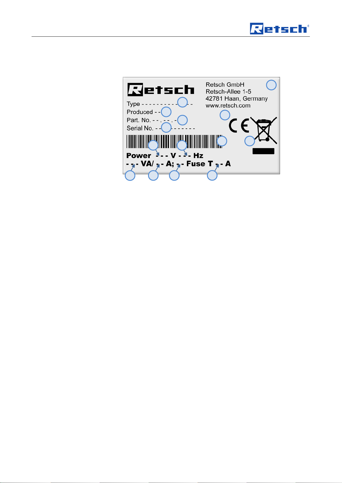
3.6 Type plate description
Pos: 5.18.2 /00 003 Standar d K apitel/Ge n er al M od ul T yp enschild @ 3\mod_1280931092443_9.doc @ 22278 @ @ 1
Fig. 1: Type plate lettering
1 Device designation
2 Year of production
3 Part number
4 Serial number
5 Manufacturer’s address
6 CE marking
7 Disposal label
8 Bar code
9 Power version
10 Mains frequency
11 Capacity
12 Amperage
13 Number of fuses
14 Fuse type and fuse strength
In the case of questions please provide the device designation (1) or the part
Pos: 5.19 /0 0005 Über schriften/ 1.1 Übersc hriften/ 1.1 Übersc hriften BD A/11 Trans porthilf e entfern en @ 0\mod_1229076673566_9.doc @ 5020 @ 2 @ 1
number (3) and the serial number (4) of the device.
3.7 Removing Transport Safeguards
Pos: 5.20 /0 0010 Bedi enungsanl eitungen K apitelsa mmlungen/ SM100/0010 SM100 Tr ansport, Li eferumfa ng und Auf stellen/1 010 SM100 M odul Tra nsporthil fe entferne n @ 3\mod_1284973889130_9.doc @ 23629 @ @ 1
12
Page 13

Transport, scope of delivery, installation
TH
Fig. 2: Removing the transport aid
Only use the transport aid (TH) when lifting the device. The device weighs approx.
73 kg. Select secure lifting equipment that is approved for this weight.
Keep the eyebolt (TH) for transportation at a later date.
Pos: 5.21 /0 0010 Bedi enungsanl eitungen K apitelsa mmlungen/------- Seit enumbruc h ----------- @ 0\mod_12223443737 58_0.doc @ 2386 @ @ 1
The eyebolt must be removed before assembling the hopper.
13
Page 14
Transport, scope of delivery, installation
TR
RS
TS
SQ
RS
TR
RS
Pos: 5.22 /0 0005 Über schriften/ 1.1 Übersc hriften/ 1.1 Übersc hriften BD A/11 Gest ell Montag e @ 3\mod_1292917288312_9.doc @ 24070 @ @ 1
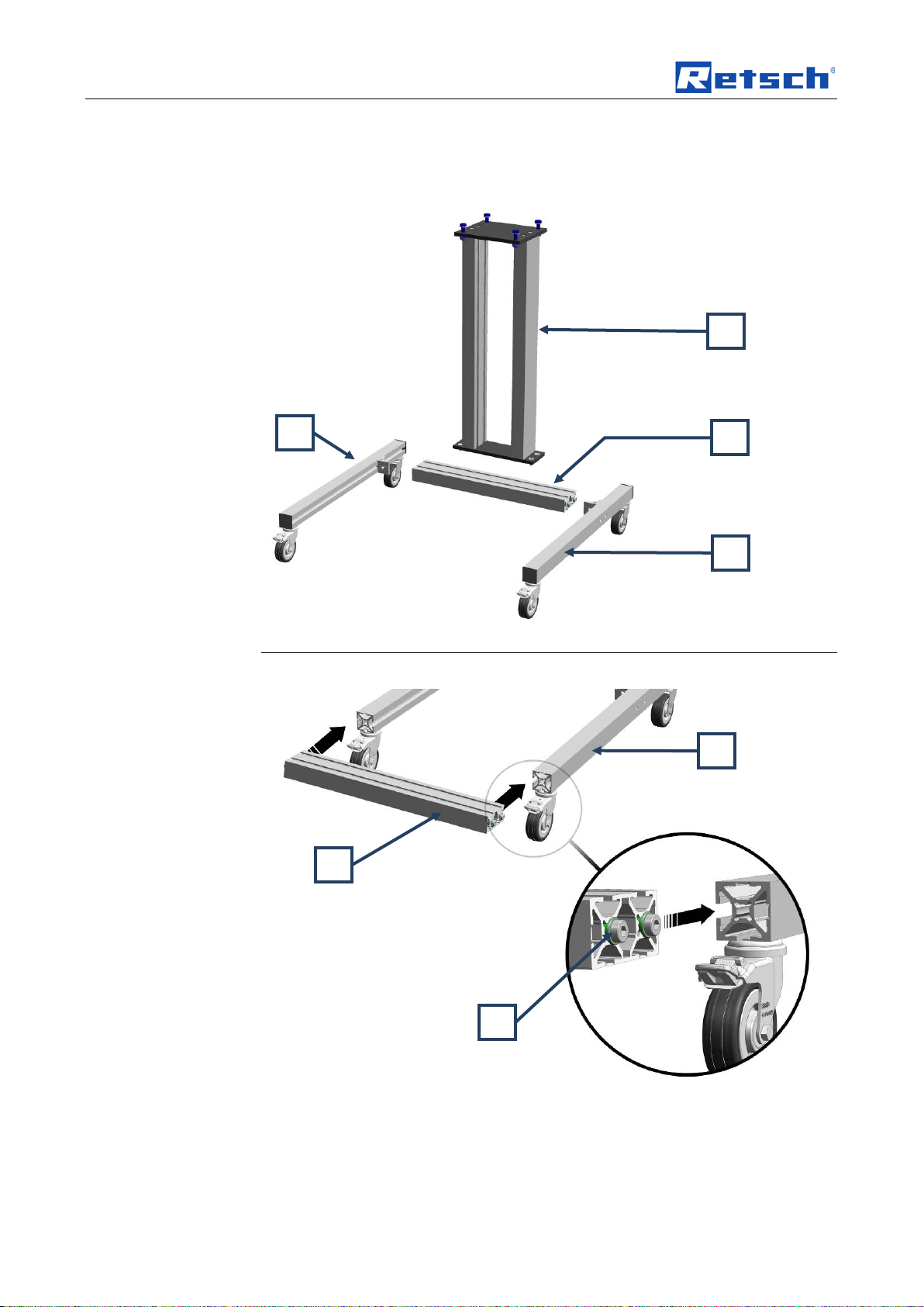
3.8 Frame assembly
Pos: 5.23 /0 0010 Bedi enungsanl eitungen K apitelsa mmlungen/ SM100/0010 SM100 Tr ansport, Li eferumfa ng und Auf stellen/1 020 SM100 M odul Ges tell monti eren @ 3\ mod_1292496265450_9.doc @ 24060 @ @ 1
Fig. 3: Components of the stand
The components come pre-assembled to simplify assembly of the frame.
14
Fig. 4: Assembling the crossbar
• Where necessary slightly loosen the four screws (TS) on the crossbar (TR).
• Slide the crossbar into the lateral guides of the left and right roller track (RS).
Page 15
Transport, scope of delivery, installation
TR
WS
WS
SW
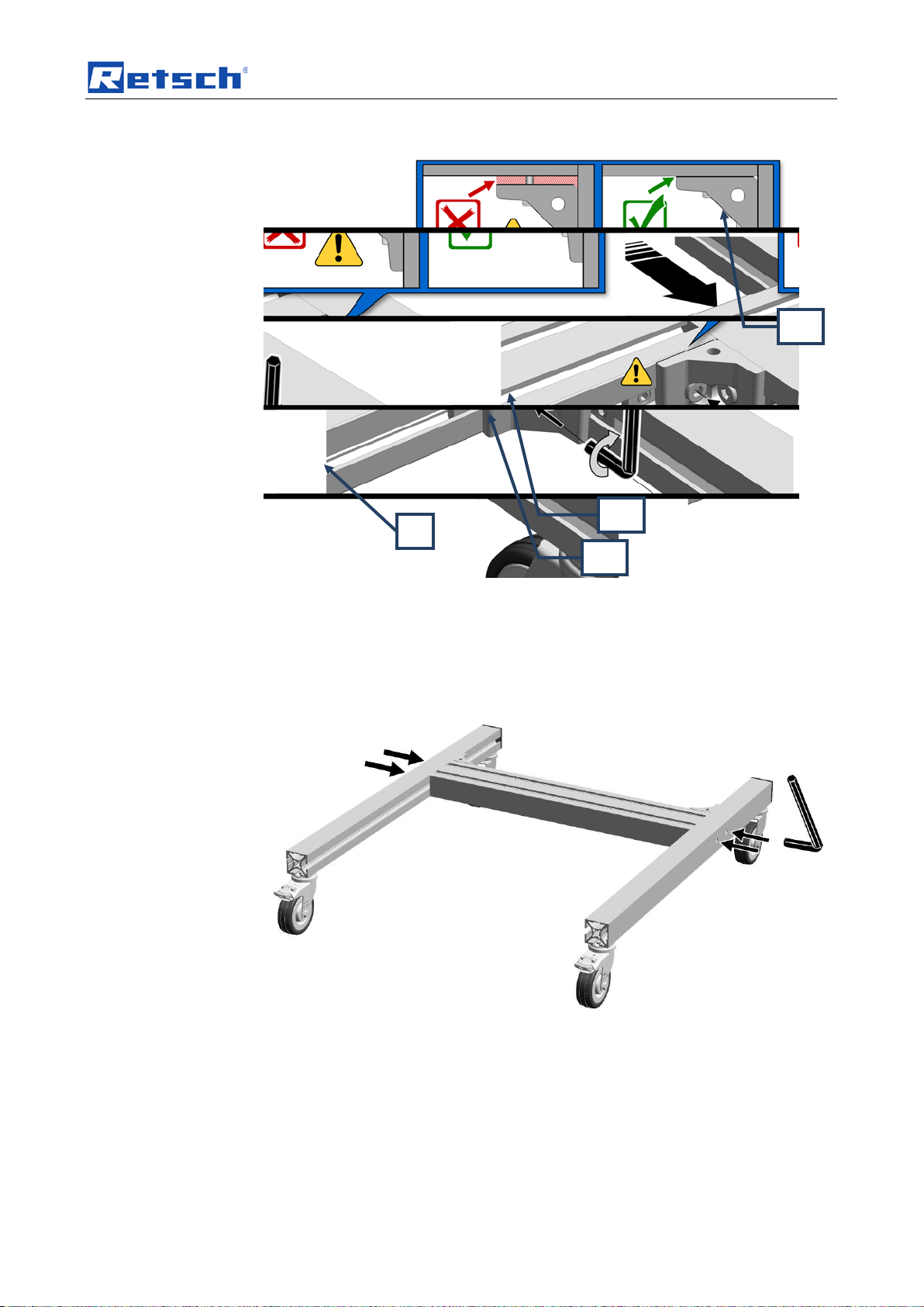
Fig. 5: Fastening the crossbar angle bracket
NB
Ensure that the crossbar (TR) is aligned flush wit h the pre-assembled angle
section (WS).
Tighten the screw on the left and right of the angle section (SW).
Fig. 6: Screwing the crossbar tight
• Tighten the four Allen screws.
15
Page 16

Transport, scope of delivery, installation
SQ
Fig. 7: Mounting the side protective caps
• Place the four black plastic caps on the openings.
Fig. 8: Mounting the front protective caps
• Place the two caps on the ends of the roller track.
16
Page 17

Transport, scope of delivery, installation
Fig. 9: Placing the crossbar on the stand
• Place the stand (SQ) on the crossbar.
Fig. 10: Points for securing the stand
Fig. 11: Screwing the stand onto the crossbar
• Screw the stand (SQ) onto the crossbar.
Fig. 12: Assembling the SM 100
• Then place the SM100 on the base frame.
17
Page 18

Transport, scope of delivery, installation
WARNING
W0004
Risk of injury to skin and hands
NOTICE
Transport safeguard
TH
TS
S T TV
Pos: 5.24 /0 0005 Über schriften/ 1.1 Übersc hriften/ 1.1 Übersc hriften BD A/11 Mont age des Ein fülltric hters @ 2\mod_1258709491283_9.doc @ 17540 @ @ 1
• Using the 4 screws, screw the SM100 housing tightly onto the base frame.
3.9 Mounting the Feed Hopper
Pos: 5.25 /0 0004 Warn hinweise/ W0004 WARN UNG sch nell rotier ende Mess er @ 3\mod_1280230540628_9.doc @ 22034 @ @ 1
Fast rotating cutting blade
– There is a risk of injuring hands, fingers and skin.
• Never operate the device without a feed hopper.
Pos: 5.26 /0 0004 Warn hinweise/H 0019 HIN WEIS Trans portsich erung SM3 00 @ 0\mod_1228918883206_9.doc @ 4809 @ @ 1
– Components may be damaged.
• Operate the machine only without the transport safeguard or
transport the machine only with transport safeguard.
Pos: 5.27 /0 0005 Über schriften/ 1.1.1 Über schrifte n/111 Trans portsic herung entf ernen @ 2\ mod_1258709630300_9.doc @ 17547 @ @ 1
3.9.1 Removing the Transport Safeguard
Pos: 5.28 /0 0010 Bedi enungsanl eitungen K apitelsa mmlungen/ SM100/0010 SM100 Tr ansport, Li eferumfa ng und Auf stellen/1 015 SM100 M odul Tra nsportsic herung entf ernen @ 3 \mod_1284973890770_9.doc @ 23638 @ @ 1
1.
Pos: 5.29 /0 0005 Über schriften/ 1.1.1 Über schrifte n/111 Einf ülltrichter montier en @ 2\mod_1258709690814_9.doc @ 17554 @ @ 1
3.9.2 Mounting the Feed Hopper
Pos: 5.30 /0 0010 Bedi enungsanl eitungen K apitelsa mmlungen/ SM100/0010 SM100 Tr ansport, Li eferumfa ng und Auf stellen/1 005 SM100 M odul Einfüll t r ic hter monti er e n @ 3\ mod_1284973885973_9.doc @ 23620 @ @ 1
18
Fig. 13: Removing the transpor t lock
• Remove the transport aid (TH).
• Turn the door lock grip (TV) until the door can be opened.
• Open the grinding area door (T).
• Remove the two safety screws (S).
NB
Retain the transport lock (TS) for transportation at a later date.
Page 19

Transport, scope of delivery, installation
CAUTION
S T B R D
S
Fig. 3: Mounting the feed hopper
• Open the grinding area door (T).
• Pull the plunger (B) so it engages in the uppermost position.
• Place the feed hopper (R) on the device (see diagram)
It is possible for the feed hopper (R) to fall from the device as long
as it is not secured by the three socket screws.
• Unlock the locking pins (D) of the plunger (B).
• Slide the plunger down.
• Screw in the three supplied socket screws (S).
• Initially only tighten the screws loosely.
• Close the grinding area door (T).
• Twist the rotary grip of the grinding area door.
• Align the feed hopper so that the plunger can be easily moved up and down
without tilting.
• Screw the three socket screws tight (10Nm).
• Check again that the plunger can be easily moved up and down without
tilting.
NB
Pos: 5.31 /0 0005 Über schriften/ 1.1 Übersc hriften/ 1.1 Übersc hriften BD A/11 Aufs tellen des Gerätes @ 0\mod_1226498849756_9.doc @ 3464 @ 2 @ 1
The grinding area door and the grip of the door lock are somewhat stiff when new.
3.10 Installation of the machine
Pos: 5.32 /0000 3 S t an d ard Kapitel/ General Mod ul Aufstell u ng shöhe @ 0\mod_1228918538349_9.doc @ 4724 @ @ 1
Pos: 5.33 /0 0004 Warn hinweise/H 0004 HIN WEIS Bode n Aufstell en Vibrati onen Bode n @ 0\mod_1228918882236_9.doc @ 4774 @ @ 1
Installation height: maximum 2000 m above sea level
19
Page 20

Transport, scope of delivery, installation
NOTE
Installation
NOTICE
Installation of the machine
– Depending on the operating status of the mill, there may be slight
vibrations.
• Place the mill on an even, flat and balanced supporting surface only.
The supporting surface must be stable and must not vibrate.
Pos: 5.34 /0000 4 W arnhinwei s e/ H 0002 HIN WEIS Aufstel lung Zug ang Geräte steckdos e @ 0\mod_1233836960983_9.do c @ 5820 @ @ 1
– It must be possible to disconnet the machine from the mains at any time.
• Install the machine such that the connection for the mains cable is
easily accessible.
Pos: 6.1 /00 010 Bedie nungsanlei tungen Ka pitelsam mlungen/------- Seit enumbruch ----------- @ 0\mod_1222344373758_0.doc @ 2386 @ @ 1
20
Page 21

Technical data
NOTICE
Area of use of the machine
Pos: 6.2 /00 005 Übers chriften/ 1. Übersc hriften/1 T echnische Daten @ 0 \mod_1222344525522_9.doc @ 2407 @ 1 @ 1
4 Technical data
Pos: 6.3 /00 005 Übers chriften/ 1.1 Übersc hriften/1. 1 Überschr iften BDA/ 11 Einsatz der Masc hine bei bestimmung sgemäßer Verwendu ng @ 0\mod_1226476732248_9.doc @ 324 3 @ 2 @ 1
4.1 Use of the machine for the intended purpose
Pos: 6.4 /00 010 Bedie nungsanlei tungen Ka pitelsam mlungen/SM 100/0005 SM100 Tec hnische Da ten/0535 SM100 Mod ul Zielgru ppe Maschi nentyp @ 3\mod_1284973723946_9.doc @ 23584 @ @ 1
Target group: Operating companies, operators
Pos: 6.5 /00 010 Bedie nungsanlei tungen Ka pitelsam mlungen/SM 100/0005 SM100 Tec hnische Da ten/0530 SM100 Mod ul Einsatz bei besti mmungsge mäß er Verwen d ung @ 3\ mod_1284973723227_9.doc @ 23575 @ @ 1
Designation of machine model: SM 100
This powerful cutting mill is used to grind elastic and fibrous products and product
mixtures in batches or continuously. In addition this device is fundamentally not
designed to grind wet or damp materials. The special moulding of the cutting tools
in conjunction with the drive produces fast, efficient grinding without the ground
material interrupting the procedure.
With the following special features
The new powerful grinding mill can successfully perform difficult grinding tasks
where other grinding mills fail. The device facilitates particularly effective
preliminary grinding of heterogeneous material mixtures such as waste or
electronic components. Analytical fineness can usually be achieved in one step.
The cutting mill can also be used successfully with a number of other materials.
The grinding material is only slightly warmed in the process so that the mill can
also be used for materials that are temperature sensitive.
Use with the large selection of sieves, hoppers and collecting vessels enables the
equipment to be adjusted to individual tasks.
Pos: 6.6 /00 004 Warnhi nweise/H 0007 HINW EIS Einsatz bereich des Gerätes 8 Stündi ger @ 1\mod_1236240219096_9.doc @ 7693 @ @ 1
Pos: 6.7 /00 005 Übers chriften/ 1.1 Übersc hriften/1. 1 Überschri ft e n BDA/11 Em mi si o ne n @ 0\mod_1226487095021_9.doc @ 3310 @ @ 1
– Fast, successive grinding by 18 spiral-shaped cutting plates distributed
round the rotor
– Parallel section rotor
– Cutting tools made from quality materials
– User-friendly with central locking and control panel
– Consistent reliability of all operational device components
– Diverse use possible due to device variations and wide range of accessories
– Powerful grinding thanks to 1,5 kW motor with high torque
– Can be cleaned very quickly due to the push-fit rotor
– Defined ultimate fineness through bottom sieves with mesh sizes of 0.25 -
20 mm
0T
– 0TThis machine is a laboratory machine designed for 8-hour single-shift
operation.
0TThis machine may not be used as a production machine nor is it
•
intended for continuous operation.
4.2 Emissions
Pos: 6.8 /00 004 Warnhi nweise/V 0044 VORS ICHT Gehör schaden ( GM300, SM 200, SM3 00) @ 1\mod_1248181519795_9.doc @ 11731 @ @ 1
21
Page 22

Technical data
CAUTION
Damage to hearing
The level of noise can be high depending on the type of material,
the knife used, the speed set and the duration of the grinding
process.
- Noise that is excessive in terms of level and duration can cause
impaired or permanently damaged hearing.
• Ensure suitable sound-proofing measures or wear
hearing protection.
Pos: 6.9 /00 010 Bedie nungsanlei tungen Ka pitelsam mlungen/SM 100/0005 SM100 Tec hnische Da ten/0515 SM100 Mod ul Emmisi onen @ 3\mod_1284973721024_9.doc @ 23548 @ @ 1
Noise emissions in accordance with DIN 45635-31-01-KL3.
Emissions at 1m distance:
– approx. 68 dB (A) when idling
When grinding depending on the material to be ground:
Pos: 6.10 /0 0005 Über schriften/ 1.1 Übersc hriften/ 1.1 Übersc hriften BD A/11 Sch utzart @ 0\ mod_1226491839164_9.doc @ 3328 @ @ 1
– approx. 85 to 95 dB (A) with peaks up to 110 dB (A)
4.3 Degree of protection
Pos: 6.11 /0 0010 Bedi enungsanl eitungen K apitelsa mmlungen/ SM100/0005 SM100 Tec hnische D aten/0510 SM100 Mo dul Schutz art @ 3\mod_1284973720243_9.doc @ 23539 @ @ 1
Pos: 6.12 /0 0005 Über schriften/ 1.1 Übersc hriften/ 1.1 Übersc hriften BD A/11 Motor drehzahl @ 1\mod_1241508280705_9.doc @ 8763 @ @ 1
– IP54
4.4 Motor rotation speed
Pos: 6.13 /0 0010 Bedi enungsanl eitungen K apitelsa mmlungen/ SM100/0005 SM100 Tec hnische D aten/0545 SM100 Mo dul Motordr ehzahl @ 3\mod_1284973725337_9.doc @ 23602 @ @ 1
Pos: 6.14 /0 0005 Über schriften/ 1.1 Übersc hriften/ 1.1 Übersc hriften BD A/11 Aufna hmevolu men @ 1\mod_1241508533945_9.doc @ 8777 @ @ 1
The motor speed is 1500 minP
4.5 Receptacle volume
Pos: 6.15 /0 0010 Bedi enungsanl eitungen K apitelsa mmlungen/ SM100/0005 SM100 Tec hnische D aten/0540 SM100 Mo dul Aufnahmevolumen @ 3\mod _1284973724649_9.doc @ 23593 @ @ 1
Pos: 6.16 /0 0005 Über schriften/ 1.1 Übersc hriften/ 1.1 Übersc hriften BD A/11 Nen nleistung @ 0\mod_1226491873164_9.doc @ 3334 @ @ 1
The capacity is < 5 l and can be expanded to up to 26 l using accessories.
4.6 Rated power
Pos: 6.17 /0 0010 Bedi enungsanl eitungen K apitelsa mmlungen/ SM100/0005 SM100 Tec hnische D aten/0505 SM100 Mo dul Nennl eistung @ 3\mod_1284973718290_9.doc @ 23530 @ @ 1
Pos: 6.18 /00 005 Übers chriften/ 1.1 Übersc hriften/1. 1 Überschr iften BDA/ 11 Abmess ungen und Gewicht @ 0\mod_1226492212173_9 .doc @ 3352 @ @ 1
– 1500 W
4.7 Dimensions and weight
Pos: 6.19 /0 0010 Bedi enungsanl eitungen K apitelsa mmlungen/ SM100/0005 SM100 Tec hnische D aten/0520 SM100 Mo dul Abmes sungen un d Gewicht @ 3\mod_1284973721696_9.doc @ 23557 @ @ 1
Height: 1675 mm
Width: 582 mm
Depth: 700 mm
Weight: approx. 73 kg (without hopper, rotor and base frame)
-1
P.
22
Page 23

Operating the machine
Pos: 6.20 /0 0005 Über schriften/ 1.1 Übersc hriften/ 1.1 Übersc hriften BD A/11 Erfor derliche Standfläc he @ 0\mod_1226492678414_9.doc @ 3364 @ 2 @ 1
Fig. 4: Dimensions
4.8 Required floor space
Pos: 6.21 /0 0010 Bedi enungsanl eitungen K apitelsa mmlungen/ SM100/0005 SM100 Tec hnische D aten/0525 SM100 Mo dul Erford erliche St andfläche @ 3\mod_1284973722430_9.doc @ 23566 @ @ 1
Pos: 7.1 /00 005 Übers chriften/ 1. Übersc hriften/1 B edienung d es Gerätes @ 0\mod_1226565880211_9.doc @ 3519 @ 1 @ 1
1090 mm x 765 mm – no safety distances necessary
5 Operating the machine
Pos: 7.2 /00 005 Übers chriften/ 1.1 Übersc hriften/1. 1 Überschr iften BDA/ 11 Ansic hten des G erätes @ 0\ mod_1228990581782_9.doc @ 4966 @ 2 @ 1
5.1 Views of the Instrument
Pos: 7.3 /00 010 Bedie nungsanlei tungen Ka pitelsam mlungen/SM 100/0015 SM100 Be dienung/15 35 SM100 M odul Graf ische Ansi chten des Gerätes @ 3\ mod_1284973920444_9.doc @ 23710 @ @ 1
23
Page 24

Operating the machine
G A C
B K I H D
T
U
W
R
S
Fig. 5: Front view
24
Page 25

Operating the machine
P P I
P
O
Fig. 6: Grinding area view
Pos: 7.4 /00 010 Bedie nungsanlei tungen Ka pitelsam mlungen/------- Seit enumbruch ----------- @ 0\mod_1222344373758_0.doc @ 2386 @ @ 1
25
Page 26

Operating the machine
Pos: 7.5 /00 005 Übers chriften/ 1.1 Übersc hriften/1. 1 Überschr iften BDA/ 11 Übersi chtstabel le der Ger äteteile @ 0\mod_1228990616846_9.d oc @ 4972 @ @ 1
5.2 Overview table of the parts of the device
Pos: 7.6 /00 010 Bedie nungsanlei tungen Ka pitelsam mlungen/SM 100/0015 SM100 Be dienung/15 70 SM100 M odul Tab elle der G eräteteile @ 3\mod_1284973932336_9 .doc @ 23773 @ @ 1
Element Description Function
A
B
C
D
G
Safety guard for the feed hopper Prevents contact with the feed hopper
Plunger Releases the material feed chute in pulled state.
Metering plunger Pushes the grinding material into the feed chute area of
Locking pin Prevents, blocks or releases the fill plunger.
On/off switch Starts and stops the device
Pushes grinding material onto the rotor.
the fill plunger
– Extended: gr in ding materi al ca n be loaded.
– Inserted: gr in ding materia l re m ains in the area
of the fill plunger.
– Extended: f ree mov em ent of the
fill plunger is possible
– Released: fill plunger engages in the uppermost
position
H
I
J
K
O
P
R
S
T
Pos: 7.7 /00 010 Bedie nungsanlei tungen Ka pitelsamml ungen/------- Seite numbruch ----------- @ 0\mod_1222344373758_0.doc @ 2386 @ @ 1
U
Parallel section rotor Grinding tool
Bottom sieve Influences the ultimate fineness of the grinding material
through the size and type of perforation
Ring filter Air outlet and filter for material to be ground
Collecting receiver Collects ground material
Rotor shaft Accommodates the grinding tool
Cutting bars Counterpart to grinding tool
Feed hopper Feeding the grinding material
Feed hopper fixing screws Safety bolts for the feed hopper
Grinding Chamber door Closes the grinding area
Threaded handle Closes the grinding area door
26
Page 27

Operating the machine
CAUTION
1
or the motor is still rotating.
CAUTION
Injuries in the form of cuts
G
U
Pos: 7.8 /00005 Üb er s c hriften/1. 1 Ü b erschrifte n/1.1 Übers c hr i ft en BDA/11 Öff nen und schl i eß en des Gerätes @ 1\ mod_1241510544133_9.doc @ 8826 @ 2 @ 1
5.3 Opening and closing of the grinding chamber
Pos: 7.9 /00004 War nhinweis e/ V0063 VORS I CH T Ver l etzung dur ch dr e henden Ro tor - St illstand R otor abwar ten @ 3\mod_1311157127479_9.doc @ 25300 @ @ 1
Possibility of personal injuries
Injuries due to rotating rotor
– Reaching into the turning rotor
• Never open the grinding chamber door while the rotor
Pos: 7.10 /0 0010 Bedi enungsanl eitungen K apitelsa mmlungen/ SM100/0015 SM100 Bedien ung/1560 SM 100 Modul Öff nen und schl ieß en des Gerät es @ 3\ mod_128497392514 8_9.doc @ 23755 @ @ 1
• Stop the device by actuating the switch (G).
• Open the grinding area door by turning the handle (U).
2.V000
Pos: 7.11 /0 0005 Über schriften/ 1.1 Übersc hriften/ 1.1 Übersc hriften BD A/11 Eins etzen der Bodensieb e @ 1\mod_1241510694791_9.doc @ 8840 @ @ 1
5.4 Mounting the bottom sieve
Pos: 7.12 /0001 0 B edi enungsa nl ei t ung en Kapitels ammlung e n/ S M 1 0 0/ 0015 SM100 B edi enung/15 15 SM100 Mod ul E ins etzen der B od e nsiebe @ 3\mod_1284973915757_9.doc @ 23674 @ @ 1
Pos: 7.13 /0 0005 Über schriften/ 1.1 Übersc hriften/ 1.1 Übersc hriften BD A/11 Wechs el der Rot oren @ 1\ mod_1241510739447_9.doc @ 8847 @ @ 1
5.5 Replacing the rotor
Pos: 7.14 /0000 4 W arnhinwei se/V0027 VORSICHT S chnittver letzunge n Rotorwec hsel und R einigung @ 2\mod_1259065354428_9.doc @ 17601 @ @ 1
Pos: 7.15 /0000 4 W arnhinwei s e/ H 0012 HINWE IS Mi n der ung von Wer kzeugstan dz eiten Abrasi ve Werkstof fe @ 1\mod_1241695652739_9.doc @ 9500 @ @ 1
Fig. 7: Opening the grinding area door
• Select the appropriate bottom sieve.
• Open the mill housing and slide the bottom sieve (I) of your choice into the
device.
Sharp cutting edges on the rotors and cutting bars
– The sharp cutting edges on the rotors and cutting bars can injure hands.
• Wear protective gloves when replacing the cutting rotors and
cleaning the grinding chamber.
• Use the rotor extraction tool when handling the cutting rotors.
27
Page 28

Operating the machine
NOTE
Reduction of tool service life
NOTE
Damage to mechanical components
EG
Abrasive sample materials
– The presence of abrasive composite materials during grinding can
considerably reduce tool service life.
• When grinding electronic scrap, take the properties of the composite
materials into account.
Pos: 7.16 /0 0004 Warn hinweise/H 0003 HIN WEIS Besc hädigung von mechani schen Ba uteilen Sc hneidmühl entypisch en Blockad e @ 1\mod_1241695971578_9.doc @ 9507 @ @ 1
Blockages typical of cutting mills
– When coarse, solid material is fed in for grinding, the high feeding capacity
of the standard rotor can cause blockages that are typical of the cutting
mills.
• If blockages occur, switch off the mill immediately and remove the
clogging material.
Pos: 7.17 /0 0005 Über schriften/ 1.1.1 Über schrifte n/111 Entn ahme des R otors @ 1 \mod_1241510848930_9.doc @ 8854 @ @ 1
5.5.1 Removing the Rotor
Pos: 7.18 /0001 0 B edienung sanleitung en Kapitels ammlunge n/SM100/ 0015 SM100 Bedienu ng/1525 SM 100 Modul Entnahme des Rotors @ 3\mod_1284973917179_9.doc @ 23692 @ @ 1
• Stop the device.
• Open the grinding area door.
• Screw the removal grip (EG) on the rotor and pull the rotor from the drive
shaft.
Pos: 7.19 /0 0005 Über schriften/ 1.1.1 Über schrifte n/111 Eins etzen des Rotors @ 1\ mod_1241510902772_9.doc @ 8861 @ @ 1
Fig. 14: Removal grip
5.5.2 Inserting the Rotor
Pos: 7.20 /0001 0 B edienung sa nleitungen Kapitelsa m ml u ng e n/ SM100/00 15 SM100 Bedi en u ng / 1 5 20 SM 100 Modul Ei ns etzen des Ro tor s @ 3\mod_1284973916460_9.doc @ 23683 @ @ 1
• • Clean and lubricate the motor shaft and the rotor.
• Slide the rotor onto the motor shaft.
Apart from this the device is largely maintenance-free.
Pos: 7.21 /0 0005 Über schriften/ 1.1 Übersc hriften/ 1.1 Übersc hriften BD A/11 Filter einheit und Auffang behälter einsetzen @ 2\mod_1259075651377_9.doc @ 17623 @ @ 1
Nevertheless we recommend that the cutting tools are checked at least once a
month depending on the frequency of use.
28
Page 29

Operating the machine
BV
RB
AV
LS
5.6 Inserting the filter unit and collecting receptacle
Pos: 7.22 /0 0010 Bedi enungsanl eitungen K apitelsa mmlungen/ SM100/0015 SM100 B edienung/1 565 SM100 M odul Ri ngsieb Mont age @ 3\mod_1284973929211_9.doc @ 23764 @ @ 1
The filter unit serves as air outlet for the flow of air gener ated b y the grindi ng
rotors.
Fig. 2: Attaching and removing the filter unit
• Insert the bayonet lock (BV) on the filter unit (J) into the discharge flange
(AV) as shown in the diagram.
• Twist the filter unit in a clockwise direction to engage the bayonet lock.
• To remove the filter unit, pull the locking pins (RB) out to release the bayonet
lock (BV).
Alternatively the collecting receiver can be placed directly on the discharge flange.
The discharge of the air flow is prevented in the latching position (BV).
In the latching position (LS) a gap remains between the discharge flange and
collecting vessel; this permits air discharge.
Pos: 7.23 /0 0005 Über schriften/ 1.1 Übersc hriften/ 1.1 Übersc hriften BD A/11 Ein- / A us s c halten @ 0\mod_1229416527496_9.doc @ 5058 @ @ 1
Fig. 3: Collecting receiver and filter unit
5.7 Switching On and Off
Pos: 7.24 /0001 0 B edienung sa nleitungen Kapitelsa m ml u ng e n/ SM100/00 15 SM100 Bedi en u ng / 1 5 10 SM 100 Modul Ei n und Ausschalt en @ 3\ mod_1284973915225_9.doc @ 23665 @ @ 1
29
Page 30

Cleaning and service
G
Fig.4: On/off switch
You can switch the device on/off using the on/off switch (G). The motor starts up
or is shut down when the switch is actuated. The switch disconnects the device
Pos: 7.25 /0 0005 Über schriften/ 1.1 Übersc hriften/ 1.1 Übersc hriften BD A/11 Mahl vorgang s tarten @ 0 \mod_1227185008190_9.doc @ 3861 @ @ 1
from the mains.
5.8 Starting the grinding process
Pos: 7.26 /0 0010 Bedi enungsanl eitungen K apitelsa mmlungen/ SM100/0015 SM100 B edienung/1 545 SM100 M odul Mahl vorgang s tarten @ 3\mod_1284973923382_9.doc @ 23728 @ @ 1
NB
Only fill test material when the device is running because this may otherwise lead
to motor blockages when starting the device.
The cutting gap between the rotor and cutting bar must be checked after each
grinding operation with hard materials. The maximum cutting gap may be 0.5 mm
(minimum is 0.3 mm).
(See chapter on Adjusting the cutting bars)
Pos: 7.27 /0 0005 Über schriften/ 1.1 Übersc hriften/ 1.1 Übersc hriften BD A/11 Mahl vorgang s toppen @ 0\mod_1226909892231_9.doc @ 3643 @ @ 1
Fig. 8: Cutting gap
5.9 Stopping the grinding process
Pos: 7.28 /0 0010 Bedi enungsanl eitungen K apitelsa mmlungen/ SM100/0015 SM100 B edienung/1 550 SM100 M odul Mahl vorgang s toppen @ 3\mod_1284973924085_9.doc @ 23737 @ @ 1
Pos: 8.1 /00 005 Übers chriften/ 1. Übersc hriften/1 R einigung und Wartu ng @ 0\mod_1231167007723_9.doc @ 5450 @ @ 1
6 Cleaning and service
Pos: 8.2 /00 005 Übers chriften/ 1.1 Übersc hriften/1. 1 Überschr iften BDA/ 11 Schn eidleisten einstelle n @ 2\mod_1264610496967_9.doc @ 18737 @ @ 1
6.1 Adjusting the cutting bars
Pos: 8.3 /00 010 Bedie nungsanlei tungen Ka pitelsam mlungen/SM 100/0040 SM100 Wart ung, Rei nigung un d Verschleiß /4005 SM 100 Modul Schneidl eisten einst el l e n @ 3\ mod_1284982610681_9.doc @ 23836 @ @ 1
30
The grinding process in progress can be stopped by actuating the on/off switch.
The grinding area door can now be opened.
Page 31

Cleaning and service
U
U
W W W
1 2 3
4
The cutting gap must be checked to ensure that the device is functioning
satisfactorily (target distance 0.3mm). For this reason the cutting bars (SL) are
arranged so that they can be shifted to permit adjustments to the cutting gap.
Fig. 15: Access to the cutting bars
• Unscrew the four screws on the left-hand cover [1]..
• Unscrew the three screws on the right-hand cover [2].
• Open the grinding area door.
• Pull the rotor approx. 10 mm out of the grinding area until it can be freely
rotated.
31
Page 32

Cleaning and service
SL
SL
SL
H
BL
SL
0,3mm
Fig. 16: Freely rotate the rotor
Mind.
Fig. 17: Adjust the cutting gaps
• Using a feeler gauge (BL) check the cutting gap for all three cutting bars
(SL). It should be at least 0.3 mm.
The feeler gauge (BL) must be placed as shown in the diagram. The cutting gap
must show a uniform distance across its entire depth. For this reason check the
cutting gap across its entire depth.
The cutting edge that has the smallest distance to the knife denotes the cutting gap
(SP1). The second cutting edge can have a larger cutting gap width.
32
Page 33

Cleaning and service
SP1
Fig. 18: Cutting gap
• By twisting the stud bolts (U) to the right, slide the cutting bar closer to the
rotor blade and thereby reduce the cutting gap. Increase the cutting gap by
twisting to the left [3].
• Tighten the screw (WS) and check the cutting gap. Repeat the process if
necessary.
• After adjusting the cutting bar, tighten the screw (W) firmly again to 7Nm [4].
• Finally re-assemble the right and left-hand cover on the device.
NB
Do not set the cutting gap to less than 0.3 mm. Contact between the cutting plates
and cutting bars can damage the mechanical components.
The tightening torque of the screw (W) must be 7Nm. This is necessary to
Pos: 8.4 /00 010 Bedie nungsanlei tungen Ka pitelsam mlungen/SM 100/0040 SM100 Wart ung, Rei nigung un d Verschleiß /4006 SM 100 Modul F ilzdichtu ng - Wartu ng un d Austausch @ 5\ mod_1350892180439_9.doc @ 34930 @ 2 @ 1
guarantee that the cutting bars are securely positioned.
6.2 Felt gasket – servicing and replacement
NOTICE
Replace the felt gasket (FD) every three months. (03.182.0024)
Fig. 19: Felt gasket
• Remove the rotor (H).
• Unscrew the two screws (SD).
• Remove the sealing ring (DR) that holds the felt gasket.
33
Page 34

Cleaning and service
H
SD
SD
DR
DR
FD
Fig. 20: Dismantling the sealing ring with felt gasket
• Remove the felt gasket (FD).
NOTICE
• Oil the felt gasket before inserting it.
• Insert the new felt gasket (FD) in the sealing ring (DR).
34
Fig. 21: Inserting the felt gasket in the sealing ring
• Mount the sealing ring (DR) with the inserted felt gasket (FD).
• Tighten screws (SD).
Page 35

Cleaning and service
CAUTION
Injuries in the form of cuts
CAUTION
V0055
Cuts
WARNING
W0004
Risk of injury
SD
SD
DR
FD
Pos: 8.5 /00 005 Übers chriften/ 1.1 Übersc hriften/1. 1 Überschr iften BDA/ 11 Reinig ung @ 0\ mod_1226909670239_9.doc @ 3607 @ @ 1
6.3 Cleaning
Pos: 8.6 /00004 War nhinweis e/ V0027 VORS I CH T Sc h ni t t verletzung en Rotorw ech s el u nd Rei nigung @ 2\mod_1259065354428_9.doc @ 17601 @ @ 1
Pos: 8.7 /000 04 War nhinweis e/ V0055 VORS I CH T Sc h ni t t verletzung en Gefährdu ng durch Sch er e n a m Bo d ensieb (SM 3 00, SM200, SM1 00) @ 3\ mod_12827436092 96_9.doc @ 22867 @ @ 1
Pos: 8.8 /00010 B e di e nu ng sanleitu ng e n K a pi t el s a m ml ungen/SM 10 0/0040 SM1 0 0 War t ung, Reinig ung und Verschleiß /4010 SM10 0 Modul R einigung @ 3\mod_1289287670269_9.doc @ 24010 @ @ 1
Fig. 22: Mounting the sealing ring with felt gasket
Sharp cutting edges on the rotors and cutting bars
– The sharp cutting edges on the rotors and cutting bars can injure hands.
• Wear protective gloves when replacing the cutting rotors and
cleaning the grinding chamber.
• Use the rotor extraction tool when handling the cutting rotors.
Danger due to shears on the bottom sieve
– There is risk of cuts from the shears when inserting and removing the
bottom sieve.
• Do not put hands in the outlet hopper.
• Only change or remove the sieve when the rotor has been removed.
3.
When device is not correctly assembled after cleaning
– There is a risk of injury to the operator.
• The device may only be cleaned by skilled personnel who have been
sufficiently instructed in operating the device.
The following components on this device can be removed or moved for cleaning
purposes:
1.
35
Page 36

Cleaning and service
S
S
C
B
– Lift up the feed hopper safety guard
– Remove the feed hopper
– Remove the rotor
– Remove the sieve
– Remove the collecting receiver
– Remove the outlet flange
6.3.1 Clean the feed hopper
Abb. 23: Removing the feed hopper
Normally it is sufficient to clean the feed hopper through the fill shaft.
• To do this pull out the plunger (B) and the metering plunger (C).
6.3.1.1 Lift up the feed hopper safety guard
Fig. 24: Lifting up the fee d hopp er saf et y guard
• Loosen the screw (ES) on the feed hopper safety guard.
• Lift up the feed hopper safety guard.
If the feed hopper needs more thorough cleaning it can also be dismantled for
cleaning.
36
Page 37

Cleaning and service
WARNING
W0004
Risk of injury to skin and hands
CAUTION
TS T B
R D TS
6.3.1.2 Remove the feed hopper
2.
Fast rotating blades
– There is a risk of injury to hands, fingers and skin.
• Never operate the device without the feed hopper.
Fig. 25: Mounting the feed hopper
• Disconnect the device from the mains by pulling the plug from the socket.
• Open the grinding area door (T).
• Unscrew the three screws (TS).
• Lift the feed hopper out of the device for cleaning.
Follow the instructions in the following section to mount the feed hopper.
6.3.1.3 Mount the feed hopper
• Open the grinding area door (T).
• Place the feed hopper (R) on the device (see diagram).
It is possible for the feed hopper (R) to fall from the device as long
as it is not secured by the two socket screws.
• Screw in the two socket screws supplied(S).
• Initially only tighten the screws loosely.
• Close the grinding area door (T).
• Twist the rotary grip of the grinding area door.
• Align the feed hopper so that the plunger can be easily moved up and down
without tilting.
• Screw the three socket screws tight (10Nm).
37
Page 38

Cleaning and service
WARNING
W0004
Risk of injury to skin and hands
FS
• Check again that the plunger can be easily moved up and down without
tilting.
6.3.2 Clean grinding area
Fig. 26: Removing the rotor
• Open the grinding area door (T).
• Pull the plunger (B) into the uppermost latching position.
• Screw the removal grip (EG) onto the rotor and pull the rotor from the drive
shaft.
• Remove the sieve.
6.3.3 Remove the discharge flange
Fast rotating blades
– There is a risk of injury to hands, fingers and skin.
• Never operate the device without the discharge flange
.
3.
38
Fig. 27: Removing the discharge flange
• Loosen the screw (FS).
• Pull the discharge flange (AV) forwards out of the bracket.
Page 39

Pos: 9.1 /00 010 Bedie nungsanlei tungen Kapi t elsammlung en/------- Seiten umbruch ----------- @ 0\mod_1222344373758_0.doc @ 2386 @ @ 1
Cleaning and service
39
Page 40

Disposal
Pos: 9.2 /00 005 Übers chriften/ 1. Übersc hriften/1 E ntsorgung @ 0\mod_1234258746831_9.doc @ 6173 @ @ 1
7 Disposal
Pos: 9.3 /00 003 Stand ard Kapitel /General Modul Ents orgung @ 0\mod_1234269404935_9.doc @ 6180 @ @ 1
Please observe the respective statutory requirements with respect to disposal.
Information on disposal of electrical and electronic machines in the European
Community.
Within the European Community the disposal of electrically operated devices is
regulated by national provisions that are based on the EU Directive 2002/96/EC on
Waste Electrical and Electronic Equipment (WEEE).
Accordingly, all machines supplied after 13.08.2005 in the business-to-business
area to which this product is classified, may no longer be disposed of with
municipal or household waste. To document this they have the following label:
=== Ende der Liste für Textmar ke Inhalt == =
Fig. 28: Disposal label
Since the disposal regulations within the EU may differ from country to country we
would request you to consult your supplier.
40
Page 41

8 Index
1
1500 W................................................................ 22
A
Access to the cutting bars................................... 31
Adjust the cutting gaps ....................................... 32
Adjusting the cutting bars ................................... 30
Air discharge ....................................................... 29
Amperage ........................................................... 12
Atmospheric humidity ......................................... 10
Attaching and removing the filter unit ................. 29
B
Bar code ............................................................. 12
Bayonet lock ....................................................... 29
befestigen Winkel-Traverse ................................ 15
C
Capacity ........................................................ 12, 22
E
Electrical connection .......................................... 11
Emissions ........................................................... 21
Explanations of the safety warnings .................... 6
External fuse ...................................................... 11
Eyebolt ............................................................... 13
F
Felt gasket ......................................................... 33
Freely rotate the rotor ........................................ 32
Front view .......................................................... 24
Fuse strength ..................................................... 12
Fuse type ........................................................... 12
G
General safety instructions .................................. 7
Gestell ................................................................ 14
I
CE marking ......................................................... 12
Changes ............................................................... 5
Cleaning .............................................................. 35
Cleaning and service .......................................... 30
Collecting receiver and filter unit ........................ 29
Conditions for the place of installation ................ 10
Confirmation ......................................................... 9
Connection cable ................................................ 11
Copyright .............................................................. 5
Cutting gap ......................................................... 33
D
Degree of protection ........................................... 22
Device designation ............................................. 12
Dimensions and weight....................................... 22
Discharge flange ................................................. 29
Disposal .............................................................. 40
Disposal label ..................................................... 12
Disposal label ..................................................... 40
Inserting the filter unit and collecting receptacle 29
Inserting the Rotor ............................................. 28
Installation height ............................................... 19
Installation of the machine ................................. 19
IP54 .................................................................... 22
L
Lubrication ......................................................... 28
M
Mains frequency ................................................. 12
Maintenance-free ............................................... 28
Manufacturer’s address ..................................... 12
Maximum relative humidity ................................ 10
Moderate or mild injury ........................................ 6
Montage des Untergestells ................................ 14
Motor rotation speed .......................................... 22
Motor shaft .........................................................
Mot
or speed ....................................................... 22
Mounting the bottom sieve ................................. 27
28
41
Page 42

Mounting the feed hopper ............................. 19, 37
Mounting the Feed Hopper ................................. 18
N
Noise emission ................................................... 22
Notes on the Operating Manual ............................ 5
Number of fuses ................................................. 12
O
Opening and closing of the grinding chamber .... 27
Opening the grinding area door .......................... 27
Operating the machine ....................................... 23
Overview table of the parts of the device ........... 26
P
Packaging ........................................................... 10
Part number ........................................................ 12
Power version ..................................................... 12
property damage ................................................... 6
R
Rated power ....................................................... 22
Receptacle volume ............................................. 22
Regulations for the place of installation .............. 11
Removal grip ....................................................... 28
Removing the feed hopper ................................. 36
Removing the Rotor ............................................ 28
Removing the transport aid ................................ 13
Removing the transport lock ............................... 18
Removing the Transport Saf eguard ................... 18
Required floor space .......................................... 23
S
Safety warnings ................................................... 6
Schutzkappen .................................................... 16
Sealing ring ........................................................ 34
Serial number ..................................................... 12
serious injury ........................................................ 6
Service Address ................................................... 8
Ständer Einzelteile ............................................. 14
Starting the grinding process ............................. 30
Stopping the grinding process ........................... 30
Switching On and Off ......................................... 29
T
Target group ........................................................ 7
Technical data .................................................... 21
Temperature fluctuation and condensed water . 10
Transport ............................................................ 10
Transport, scope of delivery, installation ........... 10
Traverse montieren ............................................ 14
Type plate .......................................................... 11
type plate description ......................................... 12
Type plate lettering ............................................ 12
U
Untergestell ........................................................ 14
Use of the machine for the intended purpose .... 21
V
Removing Transport Safeguards ........................ 12
Repairs.................................................................. 8
Replacing the rotor ............................................. 27
42
Views of the Instrument ..................................... 23
Y
Year of production .............................................. 12
Page 43

Page 44

Page 45

Authorized person for the compilation of technical documents:
Certificate of CE-Conformity according to:
LABORATORY CUTTING MILL
CERTIFICATE OF CE-CONFORMITY
Translation
SM100
EC Mechanical Engineering Directive 2006/42/EC
Applied harmonized standards, in particular:
DIN EN ISO 12100 Security of machines
EC Directive Electromagnetic Compatibility 2004/108/EC
Applied standards, in particular:
DIN EN 55011 B / Generic standard interference emission - living areas DIN EN 61326-1 Immunity
Additional applied standards, in particular
DIN EN 61010 Safety prescriptions concerning measuring-, operating-, controlling- and
laboratory equipment
J. Bunke (technical documentation)
The following records are held by Retsch GmbH in the form of Technical Documentation:
Detailed records of engin eering dev elopm ent, constru ction plans, s tudy (anal ysis) of the m easures required for
conformity assurance, analysis of the residual risks involved and operating instructions in due form according to
the approved regulations for preparation of user information data.
The CE-conformity of the Retsch laboratory cutting mill SM100 is assured herewith.
In case of a modification to the machine not previously agreed with us as well as the use of not
licensed spare parts and accessories this certificate will lose its validity.
Retsch GmbH Haan, October 2010
Ralf Eisenbach Dipl.-Ing.
FB-EW-805-069 (E) Änderungsstand B 01.2012
Retsch GmbH • Retsch- Allee 1- 5 • 42781 Haan • Germany • www.retsch.com
43
Page 46

Page 47

Page 48

Copyright
® Copyright by
Retsch GmbH
Haan, Retsch-Allee 1-5
D-42781 Haan
Federal Republic of Germany
 Loading...