

Page 1
Manual
Sample Divider PT100
Translation
© Retsch GmbH, 42781 Haan, Retsch-Allee 1-5, Germany 07.11.2012 0002
Page 2

Copyright
© Copyright by
Retsch GmbH
Haan, Retsch-Allee 1-5
D-42781 Haan
Federal Republic of Germany
2
Page 3

1 Notes on the Operating Manual ............................................................................................................ 5
1.1 Explanations of the safety warnings .................................................................................................. 6
1.2 General safety instructions ................................................................................................................ 7
1.3 Repairs ............................................................................................................................................... 8
2 Confirmation ........................................................................................................................................... 9
3 Transport, scope of delivery, installation .......................................................................................... 10
3.1 Packaging ........................................................................................................................................ 10
3.2 Transport.......................................................................................................................................... 10
3.3 Temperature fluctuations and condensed water ............................................................................. 10
3.4 Conditions for the place of installation ............................................................................................. 10
3.5 Installation of the machine ............................................................................................................... 10
3.6 Type plate description ...................................................................................................................... 10
3.7 Electrical connection ........................................................................................................................ 11
4 Technical data ....................................................................................................................................... 11
4.1 Use of the machine for the intended purpose.................................................................................. 12
4.2 Emissions......................................................................................................................................... 12
4.3 Degree of protection ........................................................................................................................ 12
4.4 Drive output...................................................................................................................................... 12
4.5 Rotation speed ................................................................................................................................. 13
4.6 Rated power .................................................................................................................................... 13
4.7 Feed size ......................................................................................................................................... 13
4.8 Receptacle volume .......................................................................................................................... 13
4.9 Dimensions and weight .................................................................................................................... 13
4.10 Required floor space ........................................................................................................................ 15
5 Operating the machine ........................................................................................................................ 16
5.1 Views of the Instrument ................................................................................................................... 16
5.2 Overview table of the parts of the device ........................................................................................ 17
5.3 Operating elements and displays .................................................................................................... 18
5.4 Overview Table of the Operating Elements and the Display ........................................................... 18
5.5 Mounting the dividing head/dg_bm "text_mod_1315215336450_0001"> ....................................... 18
5.6 Inserting sample vessel ................................................................................................................... 19
5.6.1 Inserting the sample container into the quick-release sample outlet........................................... 20
5.7 Switching On and Off ....................................................................................................................... 21
5.8 Starting, Interrupting, Stopping ........................................................................................................ 21
5.8.1 Starting ......................................................................................................................................... 21
5.8.2 Interrupting ................................................................................................................................... 21
5.8.3 Stopping ....................................................................................................................................... 21
5.9 Process Run Duration ...................................................................................................................... 22
3
Page 4

5.9.1 Process run times ........................................................................................................................ 22
5.9.2 Continuous run............................................................................................................................. 22
5.10 Attaching vibratory feeder ................................................................................................................ 22
5.11 Creating interface connection .......................................................................................................... 24
5.12 Starting device and vibratory device simultaneously ....................................................................... 26
5.13 Replacing the machine fuses........................................................................................................... 27
6 Cleaning and service ........................................................................................................................... 27
7 Fault messages ..................................................................................................................................... 28
8 Disposal ................................................................................................................................................. 29
9 Index ...................................................................................................................................................... 30
Appendix ............................................................................................................................... following pages
4
Page 5

Notes on the Operating Manual
Pos: 1.1 /00005 Überschriften/1. Übersc hriften/1 Hinweise zur Bedienungsanleitung @ 0\mod_1222347415287_9.doc @ 26 31 @ 1 @ 1
1 Notes on the Operating Manual
Pos: 1.2 /00010 Bedienungsanleitungen Kapitelsammlungen/CryoMill/0001 Hinweis e zur Bedienungsanleitung/Modul Hinweis zur Bedienungsanleitung @ 0\mod_122 2347341773_9.doc @ 2540 @ @ 1
This operating manual is a technical guide on how to operate the device safely and
it contains all the information required for the areas specified in the table of
contents. This technical documentation is a reference and instruction manual. The
individual chapters are complete in themselves.
Familiarity (of the respective target groups defined according to area) with the
relevant chapters is a precondition for the safe and appropriate use of the device.
This operating manual does not contain any repair instructions. If faults arise or
repairs are necessary, please contact your supplier or get in touch with Retsch
GmbH directly.
Application technology information relating to samples to be processed is not
included but can be read on the Internet on the respective device’s page at
Pos: 1.3 /00010 Bedienungsanleitungen Kapitelsammlungen/CryoMill/0001 Hinweis e zur Bedienungsanleitung/Modul Änderung en @ 0\mod_1222347341241_9.doc @ 2 526 @ @ 1
www.retsch.com.
Changes
Pos: 1.4 /00010 Bedienungsanleitungen Kapitelsammlungen/CryoMill/0001 Hinweis e zur Bedienungsanleitung/Modul Urheberrech t @ 0\mod_1222347342038_9.doc @ 2 547 @ @ 1
Subject to technical changes.
Pos: 2.1 /00010 Bedienungsanleitungen Kapitelsammlungen/------- Seitenumbruch ----------- @ 0\mod_1222344373758_0.doc @ 2386 @ @ 1
Copyright
Disclosure or reproduction of this documentation, use and disclosure of its contents
are only permitted with the express permission of Retsch GmbH.
Infringements will result in damage compensation liability.
5
Page 6
Notes on the Operating Manual
WARNING
Type of danger / personal injury
Source of danger
– Possible consequences if the dangers are not observed.
• Instructions on how the dangers are to be avoided.
WARNING
CAUTION
Type of danger / personal injury
Source of danger
– Possible consequences if the dangers are not observed.
• Instructions on how the dangers are to be avoided.
CAUTION
NOTICE
Nature of the property damage
Source of property damage
– Possible consequences if the instructions are not observed.
• Instructions on how the dangers are to be avoided.
Pos: 2.2 /00005 Überschriften/1.1 Überschrif ten/1.1 Überschriften BDA/11 Erklärunge n zu den Sicherheitswarnungen @ 0\m od_1222344569771_9.doc @ 2484 @ 2 @ 1
1.1 Explanations of the safety warnings
Pos: 2.3 /00003 Standard Kapitel/General Modul Warnhinweise Erklärung neu @ 0\ mod_1234858329746_9.doc @ 6190 @ @ 1
In this Operating Manual we give you the following safety warnings
Serious injury may result from failing to heed these safety warnings. We give you
the following warnings and corresponding content.
We also use the following signal word box in the text or in the instructions on action
to be taken:
Moderate or mild injury may result from failing to heed these safety warnings.
We give you the following warnings and corresponding content.
Pos: 2.4 /00010 Bedienungsanleitungen Kapitelsammlungen/------- Seitenumbruch ----------- @ 0\mod_1222344373758_0.doc @ 2386 @ @ 1
We also use the following signal word box in the text or in the instructions on action
to be taken:
In the event of possible property damage we inform you with the word
“Instructions” and the corresponding content.
We also use the following signal word in the text or in the instructions on action to
be taken:
NOTICE
6
Page 7
Notes on the Operating Manual
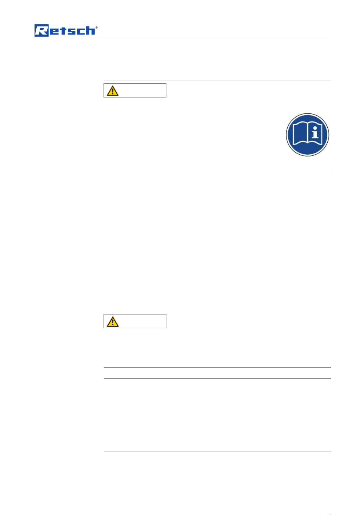
CAUTION
Read the Operating Manual
Non-observance of these operating instructions
– The non-observance of these operating instructions can
result in personal injuries.
• Read the operating manual before using the device.
• We use the adjacent symbol to draw attention to the
necessity of knowing the contents of this operating
manual.
CAUTION
Changes to the machine
– Changes to the machine may lead to personal injury.
• Do not make any change to the machine and use spare parts and
accessories that have been approved by Retsch exclusively.
NOTICE
Changes to the machine
– The conformity declared by Retsch with the European Directives will lose
its validity.
– You lose all warranty claims.
• Do not make any change to the machine and use spare parts and
accessories that have been approved by Retsch exclusively.
Pos: 2.5 /00005 Überschriften/1.1 Überschrif ten/1.1 Überschriften BDA/11 Generelle Sicherheitshinweise @ 0\mod_12223445 68974_9.doc @ 2463 @ @ 1
1.2 General safety instructions
Pos: 2.6 /00004 Warnhinweise/V0002 V ORSICHT Bedienungsanleitung lesen @ 2\ mod_1263894982815_9.doc @ 18630 @ @ 1
Pos: 2.7 /00003 Standard Kapitel/General Modul Zielgruppe und Sicherheit @ 0\mo d_1228722955300_9.doc @ 4100 @ @ 1
Target group : All persons concerned with the machine in any form
This machine is a modern, high performance product from Retsch GmbH and
complies with the state of the art. Operational safety is given if the machine is
handled for the intended purpose and attention is given to this technical
Pos: 2.8 /00003 Standard Kapitel/General Modul Sicherheitshinweise @ 0\mod_12 28722954800_9.doc @ 4086 @ @ 1
Pos: 2.9 /00004 Warnhinweise/V0015 VORS ICHT + HINWEIS Sach- und Person enschäden @ 1\mod_1236238456676_9.doc @ 7642 @ @ 1
documentation.
You, as the owner/managing operator of the machine, must ensure that the people
entrusted with working on the machine:
• have noted and understood all the regulations regarding safety,
• are familiar before starting work with all the operating instructions and
specifications for the target group relevant for them,
• have easy access always to the technical documentation for this machine,
• and that new personnel before starting work on the machine are familiarised
with the safe handling of the machine and its use for its intended purpose,
either by verbal instructions from a competent person and/or by means of
this technical documentation.
Improper operation can result in personal injuries and material damage. You are
responsible for your own safety and that of your employees.
Make sure that no unauthorised person has access to the machine.
Pos: 2.10 /00010 Bedienungsanleitungen K apitelsammlungen/------- Seitenumbruch ----------- @ 0\mod_1222344373758_0.d oc @ 2386 @ @ 1
7
Page 8

Notes on the Operating Manual
The Retsch representative in your country
Your supplier
Retsch GmbH directly
Pos: 2.11 /00005 Überschriften/1.1 Übersc hriften/1.1 Überschriften BDA/11 Reparature n @ 0\mod_1223624336511_9.doc @ 2978 @ @ 1
Reperaturen
1.3 Repairs
Pos: 2.12 /00003 Standard Kapitel/Gen eral Modul Reparaturen @ 0\mod_12287229 54535_9.doc @ 4079 @ @ 1
This operating manual does not contain any repair instructions. For your own
safety, repairs may only be carried out by Retsch GmbH or an authorized
representative or by Retsch service engineers.
In that case please inform:
Your Service Address:
Pos: 3.1 /00020 BDA Software/20005 PM GC Kapitelsammlung/- - - - Seitenumbruc h - - - - @ 0\mod_1208857688413_0.doc @ 337 @ @ 1
8
Page 9

Confirmation
I have read and taken note of the contents of all chapters in this operating
manual as well as all safety instructions and warnings.
User
Surname, first name (block letters)
Position in the company
Signature
Service technician or operator
Surname, first name (block letters)
Position in the company
Place, date and signature
Pos: 3.2 /00020 BDA Software/20005 PM GC Kapitelsammlung/Überschriften/1. Üb erschriften/1 Bestätigung (Formular für den Be treiber) @ 0\mod_1208870841095_9.d oc @ 430 @ 1 @ 1
Bestätigung
2 Confirmation
Pos: 3.3 /00003 Standard Kapitel/General Modul Bestätigung @ 0\mod_122872296 2707_9.doc @ 4114 @ @ 1
This operating manual contains essential instructions for operating and maintaining
the device which must be strictly observed. It is essential that they be read by the
operator and by the qualified staff responsible for the device before the device is
commissioned. This operating manual must be available and accessible at the
place of use at all times.
The user of the device herewith confirms to the managing operator (owner) that
(s)he has received sufficient instructions about the operation and maintenance of
the system. The user has received the operating manual, has read and taken note
of its contents and consequently has all the information required for safe operation
and is sufficiently familiar with the device.
As the owner/managing operator you should for your own protection have your
employees confirm that they have received the instructions about the operation of
the machine.
Pos: 4.1 /00010 Bedienungsanleitungen Kapitelsammlungen/------- Seitenumbruch ----------- @ 0\mod_1222344373758_0.doc @ 2386 @ @ 1
9
Page 10

Transport, scope of delivery, installation
NOTICE
Transport
– Mechanical or electronic components may be damaged.
• The machine may not be knocked, shaken or thrown during
transport.
NOTICE
Temperature fluctuations
The machine may be subject to strong temperature fluctuations during transport
(e.g. aircraft transport)
– The resultant condensed water may damage electronic components.
• Protect the machine from condensed water.
NOTICE
Ambient temperature
– Electronic and mechanical components may be damaged and the
performance data alter to an unknown extent.
• Do not exceed or fall below the permitted temperature range of the
machine (5°C to 40°C / ambient temperature).
Pos: 4.2 /00005 Überschriften/1. Überschri ften/1 Verpackung, Transport und Aufst ellung @ 0\mod_1226494451893_9.doc @ 3380 @ 1 @ 1
3 Transport, scope of delivery, installation
Pos: 4.3 /00005 Überschriften/1.1 Überschrif ten/1.1 Überschriften BDA/11 Verpackung @ 0\mod_1226495088973_9.doc @ 33 92 @ 2 @ 1
3.1 Packaging
Pos: 4.4 /00003 Standard Kapitel/General Modul Verpackung @ 0\mod_12289846 18355_9.doc @ 4892 @ @ 1
Pos: 4.5 /00005 Überschriften/1.1 Überschrif ten/1.1 Überschriften BDA/11 Transport @ 0\mod_1226495164391_9.doc @ 3398 @ 2 @ 1
3.2 Transport
Pos: 4.6 /00004 Warnhinweise/H0017 H INWEIS Transport @ 0\mod_1228918883 019_9.doc @ 4802 @ @ 1
Pos: 4.7 /00005 Überschriften/1.1 Überschrif ten/1.1 Überschriften BDA/11 Temperatursc hwankungen @ 0\mod_1226495190 738_9.doc @ 3404 @ 2 @ 1
3.3 Temperature fluctuations and condensed water
Pos: 4.8 /00004 Warnhinweise/H0016 H INWEIS Temperaturschwankungen @ 0\ mod_1233564121287_9.doc @ 5570 @ @ 1
The packaging has been adapted to the mode of transport. It complies with the
generally applicable packaging guidelines.
Pos: 4.9 /00005 Überschriften/1.1 Überschrif ten/1.1 Überschriften BDA/11 Bedingung en für den Aufstellort @ 0\mod_1226497 029322_9.doc @ 3428 @ 2 @ 1
3.4 Conditions for the place of installation
Pos: 4.10 /00003 Standard Kapitel/Gen eral Modul Umgebungstemperatur 5°C - 40°C @ 0\mod_1228918538881_9.doc @ 47 45 @ @ 1
Pos: 4.11 /00004 Warnhinweise/H0021 HIN WEIS Umgebungstemperatur 5°C bis 40°C @ 0\mod_1228918883441_9.doc @ 4 816 @ @ 1
Pos: 4.12 /00005 Überschriften/1.1 Übersc hriften/1.1 Überschriften BDA/11 Aufstell en des Gerätes @ 0\mod_1226498849756 _9.doc @ 3464 @ 2 @ 1
3.5 Installation of the machine
Pos: 4.13 /00003 Standard Kapitel/Gen eral Modul Aufstellungshöhe @ 0\mod_122 8918538349_9.doc @ 4724 @ @ 1
Pos: 4.14.1 /00005 Überschriften/1.1 Ü berschriften/1.1 Überschriften BDA/11 T ypenschild Beschreibung @ 3\mod_128093395 3941_9.doc @ 22302 @ 2 @ 1
Installation height: maximum 2000 m above sea level
3.6 Type plate description
Pos: 4.14.2 /00003 Standard Kapitel/Gen eral Modul Typenschild @ 3\mod_1280 931092443_9.doc @ 22278 @ @ 1
10
Page 11
Technical data
WARNING
1 2 3 4 5 6 7 8 9
10
11
12
14
13
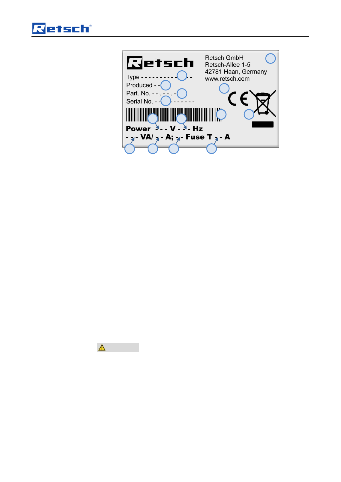
Fig. 1: Type plate lettering
1 Device designation
2 Year of production
3 Part number
4 Serial number
5 Manufacturer’s address
6 CE marking
7 Disposal label
8 Bar code
9 Power version
10 Mains frequency
11 Capacity
12 Amperage
13 Number of fuses
14 Fuse type and fuse strength
In the case of questions please provide the device designation (1) or the part
Pos: 4.15 /00005 Überschriften/1.1 Übersc hriften/1.1 Überschriften BDA/11 Elektrisc her Anschluss @ 0\mod_122656506744 5_9.doc @ 3500 @ 2 @ 1
number (3) and the serial number (4) of the device.
3.7 Electrical connection
Pos: 4.16 /00003 Standard Kapitel/Gen eral Modul Elektrischer Anschluss @ 0\m od_1228918538521_9.doc @ 4731 @ @ 1
When connecting the power cable to the mains supply, use an external fusethat
complies with the regulations applicable to the place of installation .
• Please check the type plate for details on the necessary voltage and
• Make sure the levels agree with the existing mains power supply.
• Use the supplied connection cable to connect the device to the mains power
Pos: 5.1 /00005 Überschriften/1. Übersc hriften/1 Technische Daten @ 0\mod_12 22344525522_9.doc @ 2407 @ 1 @ 1
4 Technical data
Pos: 5.2 /00005 Überschriften/1.1 Überschrif ten/1.1 Überschriften BDA/11 Einsatz der M aschine bei bestimmungsgemäßer Ver wendung @ 0\mod_1226476732248_9.do c @ 3243 @ 2 @ 1
frequency for the device.
supply.
11
Page 12

Technical data
CAUTION
Risk of explosion or fire
– On account of its design, the device is not suitable for use in hazardous
(potentially explosive) atmospheres.
• Do not operate the device in a hazardous atmosphere.
NOTICE
Area of use of the machine
– This machine is a laboratory machine designed for 8-hour single-shift
operation.
• This machine may not be used as a production machine nor is it
intended for continuous operation.
4.1 Use of the machine for the intended purpose
Pos: 5.3 /00004 Warnhinweise/V0005 VORS ICHT explosionsgefärdete Atmosphäre @ 1\mod_1239868668923_9.doc @ 814 0 @ @ 1
Pos: 5.4 /00010 Bedienungsanleitungen Kapitelsammlungen/PT100 (2011)/0010 PT1 00 Technische Daten/1505 PT100 Einsatz der Maschine bei bestimmungsgemäßer Verwendung @ 3\mod_1302779503916_9 .doc @ 24775 @ @ 1
This device is suitable for the representative divisionand reduction of free-flowing,
dispersed bulk material (Powder or Granulate) with a grain size of up to a
maximum 10 mm.
It is possible to divide into 6, 8 or 10 representative sub-samples. When using the
10-outlet dividing head, the maximum feed quantity amounts to 5,000cm3. 10
individual samples in glass bottles with a maximum of 500cm3 volume each can be
held.
For a precise division of the sample it is recommendable to feed the sample
Pos: 5.5 /00004 Warnhinweise/H0007 H INWEIS Einsatzbereich des Gerätes 8 Stün diger @ 1\mod_1236240219096_9.doc @ 7693 @ @ 1
uniformly and continuously through a Retsch vibratory feeder.
Pos: 5.6 /00005 Überschriften/1.1 Überschrif ten/1.1 Überschriften BDA/11 Emmisio nen @ 0\mod_1226487095021_9.doc @ 3 310 @ @ 1
4.2 Emissions
Pos: 5.7 /00010 Bedienungsanleitungen Kapitelsammlungen/PT100 (2011)/0010 PT 100 Technische Daten/0540 PT100 E missionen @ 3\mod_1302779502119_9.doc @ 24730 @ @ 1
Pos: 5.8 /00005 Überschriften/1.1 Überschrif ten/1.1 Überschriften BDA/11 Schutzart @ 0\mod_1226491839164_9.doc @ 3328 @ @ 1
4.3 Degree of protection
Pos: 5.9 /00010 Bedienungsanleitungen Kapitelsammlungen/PT100 (2011)/0010 PT 100 Technische Daten/0545 PT100 Schutz art @ 3\mod_1302779502369_9.doc @ 24739 @ @ 1
Pos: 5.10 /00005 Überschriften/1.1 Übersc hriften/1.1 Überschriften BDA/11 Antrieb @ 1\mod_1240475743011_9.doc @ 8557 @ @ 1
4.4 Drive output
Pos: 5.11 /00010 Bedienungsanleitungen K apitelsammlungen/PT100 (2011)/0010 PT 100 Technische Daten/0520 P1T00 A ntrieb @ 3\mod_1302779501322_9.doc @ 24703 @ @ 1
Pos: 5.12 /00005 Überschriften/1.1 Übersc hriften/1.1 Überschriften BDA/11 Drehzahl @ 1\mod_1240476189383_9.doc @ 8 585 @ @ 1
Noise data
Noise measurement in conformance to DIN 45635-31-01-KL3
The noise characteristics are also influenced by the properties of the sample.
Example idle speed
Workplace-related emission level LpAeq = 35.3 dB(A)
Example quartz
Workplace-related emission level LpAeq = 36.1 dB(A)
Operating conditions:
Dividing ratio = 8-outlet dividing head made of aluminium
Container = 8 wide-mouth bottles
Material to be divided = quartz
IP40
Stepper motor
12
Page 13

Technical data
4.5 Rotation speed
Pos: 5.13 /00010 Bedienungsanleitungen K apitelsammlungen/PT100 (2011)/0010 PT 100 Technische Daten/0530 PT100 Motordr ehzahl Teilrohr @ 3\mod_13027795018 54_9.doc @ 24721 @ @ 1
Driving head speed:
Pos: 5.14 /00005 Überschriften/1.1 Übersc hriften/1.1 Überschriften BDA/11 Nennleistu ng @ 0\mod_1226491873164_9.doc @ 3334 @ @ 1
110 rpm at 50/60Hz (± 3 min-1)
4.6 Rated power
Pos: 5.15 /00010 Bedienungsanleitungen K apitelsammlungen/PT100 (2011)/0010 PT 100 Technische Daten/0525 PT100 Nennl eistung @ 3\mod_1302779501588_9.doc @ 24712 @ @ 1
100V AC – 240 V AC 50/60Hz
Pos: 5.16 /00005 Überschriften/1.1 Übersc hriften/1.1 Überschriften BDA/11 Aufgab ekorngröße @ 3\mod_1302161462732_9.d oc @ 24620 @ 2 @ 1
65 watts / 1.6A
4.7 Feed size
Pos: 5.17 /00010 Bedienungsanleitungen K apitelsammlungen/PT100 (2011)/0010 PT 100 Technische Daten/0510 PT100 Aufga bekorngröße @ 3\mod_1302779499119_ 9.doc @ 24685 @ @ 1
– max. 10 mm for the 6-, 8- and 10-outlet dividing head large
Pos: 5.18 /00005 Überschriften/1.1 Übersc hriften/1.1 Überschriften BDA/11 Aufnahm evolumen @ 1\mod_1241508533945_ 9.doc @ 8777 @ @ 1
– max. 5 mm for the 8-outlet dividing head small
4.8 Receptacle volume
Pos: 5.19 /00010 Bedienungsanleitungen K apitelsammlungen/PT100 (2011)/0010 PT 100 Technische Daten/0560 PT100 Auffang behälter @ 3\mod_1302779503650_ 9.doc @ 24766 @ @ 1
The maximum holding capacity is 5 litres.
(Dividing head with 10 sample outlets and 10 sample vessels, each with a holding
capacity of 500 ml)
The minimum filling volume is 180 ml.
(Dividing head with 6 sample outlets and 6 sample vessels, each with a holding
Pos: 5.20 /00005 Überschriften/1.1 Übersc hriften/1.1 Überschriften BDA/11 Abmessu ngen und Gewicht @ 0\mod_1226492 212173_9.doc @ 3352 @ @ 1
capacity of 30 ml)
4.9 Dimensions and weight
Pos: 5.21 /00010 Bedienungsanleitungen K apitelsammlungen/PT100 (2011)/0010 PT 100 Technische Daten/0550 PT100 Abmess ung und Gewicht @ 3\mod_13027795 02650_9.doc @ 24748 @ @ 1
13
Page 14

Technical data
Ca. 870
Ca. 584
Ca. 510
Ca. 187
Ca. 192
Ca. 400
Ca. 150
Ca. 348
Fig. 2: Dimensions PT100 incl. sample dividers
Dimensions with vibratory feeder (without sample jars)
Height: 870 mm
Width: 400 mm
14
Page 15

Technical data
Depth: 348 mm
Dimension without vibratory feeder, dividing head and sample flasks
Height: 510 mm
Width: 572 mm
Pos: 5.22 /00005 Überschriften/1.1 Übersc hriften/1.1 Überschriften BDA/11 Erforderlich e Standfläche @ 0\mod_12264926784 14_9.doc @ 3364 @ 2 @ 1
Depth: 348 mm
4.10 Required floor space
Pos: 5.23 /00010 Bedienungsanleitungen Kapitelsammlungen/PT100 (2011)/0010 PT 100 Technische Daten/0555 PT100 Erford erliche Standfläche @ 3\mod_130277950 3369_9.doc @ 24757 @ @ 1
PT 100 incl. 10-outlet dividing head, quick-release sample outlet and 500-ml widemouth bottles:
Width: 480 mm
Pos: 6 /00010 Bedienungsanleitungen Ka pitelsammlungen/------- Seitenumbruch ----------- @ 0\mod_1222344373758_0.doc @ 2386 @ @ 1
Depth: 420 mm
15
Page 16

Operating the machine
A
B
C
K
E
Vibratory feeder
K
E
Pos: 7.1 /00005 Überschriften/1. Überschri ften/1 Bedienung des Gerätes @ 0\mod_ 1226565880211_9.doc @ 3519 @ 1 @ 1
5 Operating the machine
Pos: 7.2 /00005 Überschriften/1.1 Überschrif ten/1.1 Überschriften BDA/11 Ansichte n des Gerätes @ 0\mod_1228990581782_ 9.doc @ 4966 @ 2 @ 1
5.1 Views of the Instrument
Pos: 7.3 /00010 Bedienungsanleitungen Kapitelsammlungen/PT100 (2011)/0015 PT1 00 Bedienung/1510 PT100 Modul Ansich ten des Gerätes @ 3\mod_1302779708 679_9.doc @ 24946 @ @ 1
Fig. 2: General view of the device and the individual parts
Fig. 3: View of the on/off switch and control panel
16
Page 17

Operating the machine
Element
Description
Function
A
Dividing head hopper
Accommodates a feed hopper, available as an
accessory, or guides the sample material from the
vibratory feeder into the tube dividers.
B
Dividing head
Divides the sample among the sample containers.
C
Adapter tube with quick-release sample
outlet
Holds the sample vessels
E
Main switch
Switches the device on and off.
K
Control panel
START / STOP, time display, runtime setting
L
Fuse tray
Contains two glass fuses
M
Interface to the vibratory feeder
Links the connection cable to the vibratory feeder
N
Power socket
Connection for the mains power cable
M L N
Fig. 4: Back of the device – power connection and interface
Pos: 7.4 /00005 Überschriften/1.1 Überschrif ten/1.1 Überschriften BDA/11 Übersichtsta belle der Geräteteile @ 0\mod_122899 0616846_9.doc @ 4972 @ @ 1
5.2 Overview table of the parts of the device
Pos: 7.5 /00010 Bedienungsanleitungen Kapitelsammlungen/PT100 (2011)/0015 PT1 00 Bedienung/1515 PT100 Modul Übersich tstabelle Geräteteile @ 3\mod_130277 9708867_9.doc @ 24955 @ @ 1
Pos: 7.6 /00010 Bedienungsanleitungen Kapitelsammlungen/------- Seitenumbruch ----------- @ 0\mod_1222344373758_0.doc @ 2386 @ @ 1
17
Page 18

Operating the machine
Element
Description
Function
K1
Display
Displays the set dividing time and the error messages
K2
- button
Reduces the dividing time
K3
+ button
Increases the dividing time
K4
Green LED
Display device switched on / running
K5
Red LED
Device stopped
K6
STOP button
Stopping the device/ pause
K7
START button
Starting the device
K1
K2
K3
K7
K5
K4
K6
Pos: 7.7 /00005 Überschriften/1.1 Überschrif ten/1.1 Überschriften BDA/11 Grafische Ansichten der Bedienelemente und der A nzeige @ 0\mod_1226566362336_9.doc @ 3537 @ @ 1
5.3 Operating elements and displays
Pos: 7.8 /00010 Bedienungsanleitungen Kapitelsammlungen/PT100 (2011)/0015 PT1 00 Bedienung/1520 PT100 Modul Ansicht der Bedienelemente @ 3\mod_1 302779709117_9.doc @ 24964 @ @ 1
Pos: 7.9 /00005 Überschriften/1.1 Überschrif ten/1.1 Überschriften BDA/11 Übersichts tabelle der Bedienelemente und der Anz eige @ 0\mod_1228990697273_9.doc @ 4978 @ @ 1
Fig. 5: Control panel
5.4 Overview Table of the Operating Elements and the Display
Pos: 7.10 /00010 Bedienungsanleitungen K apitelsammlungen/PT100 (2011)/0015 PT 100 Bedienung/1515 PT100 Modul Übersic htstabelle Bedienelement @ 3\mod_13 02779928520_9.doc @ 25072 @ @ 1
Pos: 7.11 /00005 Überschriften/1.1 Übersc hriften/1.1 Überschriften BDA/11 Teilkrone montieren @ 4\mod_1315215336450_ 9.doc @ 25590 @ 2 @ 1
5.5 Mounting the dividing head/dg_bm "text_mod_1315215336450_0001">
Pos: 7.12 /00010 Bedienungsanleitung en Kapitelsammlungen/PT100 (2011)/0015 PT 100 Bedienung/1520 PT100 Modul Teil krone montieren @ 4\mod_131582580099 1_9.doc @ 25600 @ @ 1
18
Page 19

Operating the machine
A B MN
RS
DA
NT
B (from
below/inside)
Fig. 6: Mounting the dividing head
• Put the dividing head (B) on the shaft (MN) as shown in the illustration.
• Put the dividing head hopper (A) onto the axle (DA).
Fig. 7: Locking disk on the driver and dividing head viewed from below
Pos: 7.13 /00005 Überschriften/1.1 Übersc hriften/1.1 Überschriften BDA/11 Probeng efäß einsetzen @ 3\mod_1302780091987 _9.doc @ 25081 @ 2 @ 1
Make sure that one of the four grooves (NT) engages with the locking disk (RS).
5.6 Inserting sample vessel
Pos: 7.14 /00004 Warnhinweise/V0062 VOR SICHT Glassplitter @ 3\mod_130269 0193882_9.doc @ 24640 @ @ 1
19
Page 20

Operating the machine
CAUTION
1.V0062
Injuries in the form of cuts and other personal injuries
Danger from glass splitters
– Injuries in the form of cuts can be caused by damaged sample flasks and
glass splitters.
• Replace damaged sample flasks
• Do not touch glass splitters with your hands.
CAUTION
Danger of personal injury
Dangerous nature of the sample
– Depending on the dangerous nature of your sample, take the
necessary measures to rule out any danger to persons.
• Observe the safety guidelines and datasheets of your
sample material.
NOTICE
2.H0057
– It must be ensured that all tube dividers are fitted with sample containers.
Otherwise, the sample will be scattered through the missing sample
containers into the environment. (Loss of material)
– Make sure the sample containers are positioned correctly on the
mountings. If the glass bottles are inserted incorrectly, they can be
hurled out of the dividing head by centrifugal force.
H J P
Pos: 7.15 /00004 Warnhinweise/V0006 VOR SICHT Gefahr von Personenschäden G efährliche Stoffe @ 1\mod_12362384562 69_9.doc @ 7634 @ @ 1
Pos: 7.16 /00004 Warnhinweise/H0057 HIN WEIS korrekter Sitz der Probenbehälter (PT 100) @ 4\mod_1316678999198_9.doc @ 25610 @ @ 1
Pos: 7.17 /00010 Bedienungsanleitungen K apitelsammlungen/PT100 (2011)/0015 PT 100 Bedienung/1525 PT100 / PT200 Modul Einsetzen der Probengefäße @ 3\ mod_1302779709429_9.doc @ 24973 @ 3 @ 1
5.6.1 Inserting the sample container into the quick-release sample outlet
Fig. 4:
Fig. 5: Inserting the sample container (quick-release sample outlet)
• Position the sample container (H) in relation to the compression disk (J
[shaded]).
• Press the compression disk (J) along with the sample container (H)
upwards.
• Push the sample container backwards into the support (P) and lower it until it
Pos: 7.18 /00005 Überschriften/1.1 Übersc hriften/1.1 Überschriften BDA/11 Ein- / A usschalten @ 0\mod_1229416527496_9.d oc @ 5058 @ @ 1
20
locks into place.
3.
Page 21

Operating the machine
WARNING
Risk of a fatal electric shock
- An electric shock can cause injuries in the form of burns and cardiac
arrhythmia, respiratory arrest or cardiac arrest.
• Do not clean the blender under running water. Use only a cloth dampened
with water.
• Disconnect the power supply plug before cleaning the blender.
E
5.7 Switching On and Off
Pos: 7.19 /00004 Warnhinweise/W0002 WARNUNG Kabelbruch Stromstoß @ 2\ mod_1278055276120_9.doc @ 20557 @ @ 1
Pos: 7.20 /00010 Bedienungsanleitungen K apitelsammlungen/PT100 (2011)/0015 PT 100 Bedienung/1526 PT100 Modul Ein A us Schalten @ 3\mod_1303206207409_9. doc @ 25226 @ @ 1
Fig. 8: On/off switch
There is an on-and-off switch (E) located on the left side of the device under the
operating element.
Pos: 7.21 /00005 Überschriften/1.1 Übersc hriften/1.1 Überschriften BDA/11 Starten, U nterbrechen, Stoppen @ 0\mod_122941 7133049_9.doc @ 5070 @ @ 1
• Press the switch (E) to turn the device on or off.
5.8 Starting, Interrupting, Stopping
Pos: 7.22 /00010 Bedienungsanleitungen K apitelsammlungen/PT100 (2011)/0015 PT 100 Bedienung/1530 PT100 Modul Starten des Gerätes @ 3\mod_130277970967 9_9.doc @ 24982 @ 333 @ 1
5.8.1 Starting
• Press the (K7) START button.
– The green (K4) LED lights up over the (K7) START button.
– The preset dividing time can be seen in the (K1) display.
– The dividing head starts to rotate.
– The remaining dividing time minutes are shown in the display.
(except in the co mode Continuous operation)
5.8.2 Interrupting
• Press the (K6) STOP button.
– The dividing head is decelerated and the DR 100 (if one is used) switches
off.
– The dividing time is interrupted and the (K5) LED lights up in red.
– The remaining dividing time appears in the display.
5.8.3 Stopping
• Press the (K6) STOP button twice.
– The device is put into readiness mode. (Standby)
Pos: 7.23 /00005 Überschriften/1.1 Übersc hriften/1.1 Überschriften BDA/11 Durchlauf dauer @ 2\mod_1263289874150_9.doc @ 18528 @ @ 1
• Press the (K7) START button to reactivate the device.
21
Page 22

Operating the machine
K1
K2
K3
5.9 Process Run Duration
Pos: 7.24 /00010 Bedienungsanleitungen Kapitelsammlungen/PT100 (2011)/0015 PT 100 Bedienung/1535 PT100 Modul Laufzeit einstellen @ 3\mod_1302779709820_9. doc @ 24991 @ 33 @ 1
Fig. 1: Setting the processing time
5.9.1 Process run times
You can set the division process time by pressing the + button (K3) or - button
(K2).
• Press the + button (K3) repeatedly until you reach the appropriate process
run time.
You can select the following time intervals: (in minutes)
co (continually) – 1 – 3 – 5 – 10 – 20 – 30 – 40 – 50 – 60
5.9.2 Continuous run
• Press the + (K3) or (K2) button repeatedly until co appears in the display.
During the dividing time, the speed is kept at a constant level within the set
Pos: 7.25 /00005 Überschriften/1.1 Übersc hriften/1.1 Überschriften BDA/11 Zuteilger ät anbauen @ 3\mod_1302780202188 _9.doc @ 25089 @ 2 @ 1
tolerance.
5.10 Attaching vibratory feeder
Pos: 7.26 /00010 Bedienungsanleitungen K apitelsammlungen/PT100 (2011)/0015 PT 100 Bedienung/1545 PT100 Modul Anbau des Zuteilgerätes @ 3\mod_130277971 0210_9.doc @ 25009 @ @ 1
To prepare the vibratory feeder, you need the DR100 operating manual. For a
precise sample division, it is recommendable to feed the sample uniformly through
a vibratory feeder. The DR 100 vibratory feeder, which is available as an
accessory, is suitable for that purpose. The connection between the device and the
DR 100 is established by means of an interface cable, which is included in the DR
100 scope of supply. Both the device and the DR 100 require a mains power
socket, each with the same phase position, providing the appropriate voltage and
frequency (see type plate on the devices). Multi-distributor power sockets, to which
both devices can be connected, are suitable for this purpose.
22
Page 23

Operating the machine
HT
GS
GF
KN
SCH
ST
RS
Fig. 2: Mounting the vibratory feeder
– The support (HT) is already completely pre-assembled with the stand rod (ST).
• Unscrew the two rubber feet (GF) at the back of the DR100.
• Loosen the hand screw (KN).
• Take the support (HT) off the stand rod (ST).
• Connect the DR 100 and the support (HT) by means of the hexagonal cap
screws and washers (SCH).
Pay attention to the side position of the DR100 vibratory feeder. The position of the
hopper opening varies depending on the dividing head being used.
Fig. 3: Positioning the vibratory feeder
23
Page 24

Operating the machine
ST
KS1
• Remove the plastic screw (KS1).
• Screw the stand rod (ST) onto the housing.
Fig. 4: Inserting the stand rod
• Mount the (HT) support.
• Adjust the swivel distance. To do so, loosen the threaded pin (GS) in the
locking disk (RS).
Adjust the swivel distance so that the feeding chute is positioned in the centre over
the feed hopper at the anti-clockwise limit stop and the support (HT) is swung out
at the clockwise limit stop.
• Tighten the threaded pin (GS) in the locking disk (RS) again.
• Align the DR 100 chute over the PT 100 feed hopper.
The (KN) hand screw at the back of the support (HT) serves to lock the DR 100 in
position.
When the (KN) hand screw is loosened, the DR100 can be swivelled 60°. The feed
hopper with the dividing head is therefore accessible before and after the dividing
process.
NOTICE
PT 100 and DR 100 must be suitable for the same electrical mains supply (see
type plate).
Failure to comply with the ratings on the type plates on the PT 100 and DR 100
can cause damage to the electronic and mechanical components.
Pease read the DR 100 operating instructions for information on the further
Pos: 7.27 /00005 Überschriften/1.1 Übersc hriften/1.1 Überschriften BDA/11 Schnittstell enverbindung herstellen @ 3\mod_13 03201613915_9.doc @ 25210 @ 2 @ 1
operation of the DR 100.
5.11 Creating interface connection
Pos: 7.28 /00010 Bedienungsanleitungen K apitelsammlungen/PT100 (2011)/0015 PT 100 Bedienung/1546 PT100 Modul Schnittst elle anschließen @ 3\mod_13032026 86288_9.doc @ 25218 @ @ 1
• Before mounting the DR 100, read the DR 100 operating instructions.
24
Page 25

Operating the machine
DF
VK
Fig. 5: Connection of the PT100 to the DR 100
Use the interface cable contained in the scope of supply for the retrofit kit to
establish the connection between the DR 100 and the PT100.
• Insert the connection cable (VK) into the interface (DF) on the back of the
DR 100.
Fig. 6: Inserting the DR 100 connection cable
• Insert the connection cable (VK) into the interface (PF) at the back of the
PT100.
25
Page 26

Operating the machine
DS
DK
DN
DZ
VK
PF
Pos: 7.29 /00005 Überschriften/1.1 Übersc hriften/1.1 Überschriften BDA/11 Gerät un d Zuteilgerät gleichzeitig starten @ 3\ mod_1302780258781_9.doc @ 25097 @ 2 @ 1
Fig. 7: Inserting the PT100 connection cable
5.12 Starting device and vibratory device simultaneously
Pos: 7.30 /00010 Bedienungsanleitungen K apitelsammlungen/PT100 (2011)/0015 PT 100 Bedienung/1550 PT100 / PT200 Mod ul Gerät und Zuteilgerät starten @ 3\mo d_1302779710476_9.doc @ 25018 @ @ 1
• Put sample vessels onto all sample outlets on the device.
Fig. 4: Rear view of the DR100
NOTE
PT 100 and DR100 must be suitable for the same electrical mains supply, (see
type plate).
Failure to comply with the ratings on the type plate on the PT 100 and DR100 can
cause damage to electronic and mechanical components.
26
• Connect the DR100 to the mains power supply using the C13 panel-
mounted male connector (inlet) (DZ).
• Set the switch (DS) on the back of the DR100 to “Standard”.
Fig. 5: Setting the DR100 feeding speed
• Set the feeding speed regulator (DK) on the DR100 to the required position
(depending on the material to be divided).
• Fill the DR100 feed hopper.
• Adjust the slot width between the feed hopper outlet and the push-fit chute base
(feed level).
Page 27

Cleaning and service
WARNING
Risk of a fatal electric shock
- An electric shock can cause injuries in the form of burns and cardiac
arrhythmia, respiratory arrest or cardiac arrest.
• Do not clean the blender under running water. Use only a cloth dampened
with water.
• Disconnect the power supply plug before cleaning the blender.
B
The setting of the gap between the push-fit chute and the feed hopper depends on
the maximum particle size of the feed material. It should be about 3 times as large
as the max. particle size.
• Press the ON/OFF switch (DN) on the DR100 .
• Turn on the sample divider and start it.
The DR100 does not start until the sample divider has reached the nominal speed.
The DR100 switches off automatically when the nominal speed of the sample
divider varies too much or drops. If this fluctuation lasts only for a short time (<5s),
the DR100 switches on again once the nominal speed has been reached again
and the feeding process is continued. As soon as you stop the sample divider, the
Pos: 7.31 /00005 Überschriften/1.1 Übersc hriften/1.1 Überschriften BDA/11 Austausc h der Gerätesicherung @ 0\mod_12272 60127023_9.doc @ 3952 @ @ 1
DR100 stops too and the sample is not fed.
5.13 Replacing the machine fuses
Pos: 7.32 /00010 Bedienungsanleitungen K apitelsammlungen/PT100 (2011)/0015 PT100 Bedienung/1560 PT100 Modul Austa usch der Gerätesicherung @ 3\mod_130 2780460732_9.doc @ 25121 @ @ 1
Fig. 8: Fuse holder
Required fuses:
2 glass fuses T 2A (5x20mm)
• Disconnect the mains plug.
• Pull out the fuse holder (B).
• Replace the fuses.
• Insert the fuse holder.
Pos: 8.1 /00005 Überschriften/1. Überschri ften/1 Reinigung und Wartung @ 0\mod_ 1231167007723_9.doc @ 5450 @ @ 1
Only after-sales service may replace the fuses inside the device.
6 Cleaning and service
Pos: 8.2 /00004 Warnhinweise/W0003 WARNUNG Reinigung Stromstoß neu @ 1\mod_1236239978437_9.doc @ 7686 @ @ 1
Pos: 8.3 /00004 Warnhinweise/H0006 H INWEIS Defekt von Bauteilen durch Flüssig keitenEindringen von Flüssigkeiten ins Gehä useinne @ 1\mod_1248181032171_9.do c @ 11723 @ @ 1
27
Page 28

Fault messages
NOTICE
4.H0006
Defective components due to liquids
Penetration of liquids into the inside of the device
– Components are damaged and the function of the device is no longer
ensured.
• Clean the device under running water. Only use a moist cloth
NOTICE
Damage to the machine through solvents
– Solvents may damage plastic parts and the paint finish.
• It is not allowed to use solvents.
Error code
Error
Measure
F1
Motor is not running or
the rotation of the
dividing head has been
stopped manually
Press the STOP button; if the error
persists, after-sales service must be
consulted
F3
Speed too high or too
low
Press the STOP button; if the error
persists, after-sales service must be
consulted
F5
Keypad defective
Service necessary
Pos: 8.4 /00004 Warnhinweise/H0009 H INWEIS Geräteschaden durch Lösungsmit tel @ 0\mod_1231165437212_9.doc @ 544 1 @ @ 1
Pos: 8.5 /00010 Bedienungsanleitungen Kapitelsammlungen/PT100 (2011)/0025 PT1 00 Reinigung und Wartung /2505 PT100 M odul Reinigung und Wartung @ 3\mod _1302848234736_9.doc @ 25178 @ @ 1
The PT 100 laboratory sample divider is designed to allow all parts coming into
contact with materials to be removed easily without tools. In detail these are:
• dividing head or
• Wide-mouth and DURAN® laboratory bottles
• Feed hopper and DR 100 push-fit chute
When these parts are removed from the device, they can be cleaned in a water
Pos: 9.1 /00005 Überschriften/1. Überschri ften/1 Fehlermeldungen @ 2\mod_12590 56589728_9.doc @ 17580 @ @ 1
bath, under running water and in a dishwasher.
7 Fault messages
Pos: 9.2 /00010 Bedienungsanleitungen Kapitelsammlungen/PT100 (2011)/0035 PT 100 Fehlermeldungen/3505 PT100 Modul Fe hlermeldung @ 3\mod_1302781252066 _9.doc @ 25129 @ @ 1
Pos: 10.1 /00010 Bedienungsanleitungen K apitelsammlungen/------- Seitenumbruch ----------- @ 0\mod_1222344373758_0.d oc @ 2386 @ @ 1
28
Page 29

Disposal
Pos: 10.2 /00005 Überschriften/1. Überschrif ten/1 Entsorgung @ 0\mod_123425874 6831_9.doc @ 6173 @ @ 1
8 Disposal
Pos: 10.3 /00003 Standard Kapitel/Gen eral Modul Entsorgung @ 0\mod_1234269 404935_9.doc @ 6180 @ @ 1
Please observe the respective statutory requirements with respect to disposal.
Information on disposal of electrical and electronic machines in the European
Community.
Within the European Community the disposal of electrically operated devices is
regulated by national provisions that are based on the EU Directive 2002/96/EC on
Waste Electrical and Electronic Equipment (WEEE).
Accordingly, all machines supplied after 13.08.2005 in the business-to-business
area to which this product is classified, may no longer be disposed of with
municipal or household waste. To document this they have the following label:
=== Ende der Liste für Textmarke Inhalt ===
Fig. 5: Disposal label
Since the disposal regulations within the EU may differ from country to country we
would request you to consult your supplier.
29
Page 30

9 Index
4
45635-31-01-KL3 ................................................ 12
5
5,000cm3 ............................................................. 12
500cm3 ................................................................ 12
A
Amperage ........................................................... 11
attaching vibratory feeder ................................... 22
B
Back of the device .............................................. 17
Bar code ............................................................. 11
Bulk material ....................................................... 12
C
Capacity .............................................................. 11
CE marking ......................................................... 11
Division .............................................................. 12
Drive output ........................................................ 12
E
Electrical connection .......................................... 11
Emissions ........................................................... 12
Explanations of the safety warnings .................... 6
External fuse ...................................................... 11
F
F1 ....................................................................... 28
F3 ....................................................................... 28
F5 ....................................................................... 28
Fault messages .................................................. 28
feed size ............................................................. 13
free-flowing ........................................................ 12
Function ....................................................... 17, 18
Fuse strength ..................................................... 11
Changes ............................................................... 5
Cleaning and service .......................................... 27
Conditions for the place of installation ................ 10
Confirmation ......................................................... 9
Connection cable ................................................ 11
continuously ........................................................ 12
Copyright .............................................................. 5
creating interface connection .............................. 24
D
Degree of protection ........................................... 12
Description .................................................... 17, 18
Device designation ............................................. 11
Dimensions ......................................................... 14
Dimensions and weight....................................... 13
DIN 45635-31-01-KL3 ......................................... 12
dispersed ............................................................ 12
Disposal .............................................................. 29
Fuse type ........................................................... 11
G
General safety instructions .................................. 7
Grain size ........................................................... 12
Granulate ........................................................... 12
H
Holding capacity, minimum, maximum .............. 13
I
Inserting sample vessel ..................................... 19
Installation height ............................................... 10
Installation of the machine ................................. 10
M
Mains frequency ................................................. 11
Manufacturer’s address ..................................... 11
Moderate or mild injury ........................................ 6
Mounting the dividing head ................................ 18
Disposal label ..................................................... 11
Disposal label ..................................................... 29
30
N
Noise characteristics .......................................... 12
Page 31

Noise data ........................................................... 12
Noise measurement ............................................ 12
Notes on the Operating Manual ............................ 5
Number of fuses ................................................. 11
O
On/off switch ....................................................... 16
Operating elements and displays ....................... 18
Operating the machine ....................................... 16
Overview Table of the Operating Elements and
the Display ...................................................... 18
Overview table of the parts of the device ........... 17
P
Packaging ........................................................... 10
Part number ........................................................ 11
Powder ................................................................ 12
Power version ..................................................... 11
Process Run Duration ......................................... 22
property damage ................................................... 6
Q
Quick-release sample outlet ............................... 20
R
Rated power ....................................................... 13
Receptacle volume ............................................. 13
Reduction ............................................................ 12
Regulations for the place of installation .............. 11
Repairs.................................................................. 8
Replacing the machine fuses ............................. 27
Required floor space ........................................... 15
Serial number ..................................................... 11
serious injury ........................................................ 6
Service Address ................................................... 8
Speed ................................................................. 13
starting device and vibratory device
simultaneously ............................................... 26
Starting, Interrupting, Stopping .......................... 21
Stepper motor .................................................... 12
Switching On and Off ......................................... 21
T
Target group ........................................................ 7
Technical data .................................................... 11
Temperature fluctuation and condensed water . 10
Transport ............................................................ 10
Transport, scope of delivery, installation ........... 10
Type plate .......................................................... 11
type plate description ......................................... 10
Type plate lettering ............................................ 11
U
uniformly ............................................................ 12
Use ..................................................................... 12
Use of the machine for the intended purpose .... 12
V
View of the control panel ................................... 16
View of the device .............................................. 16
Views of the Instrument ..................................... 16
Volume ............................................................... 12
W
Rotation speed .................................................... 13
S
Safety warnings .................................................... 6
Workplace-related emission level ...................... 12
Y
Year of production .............................................. 11
31
Page 32

Page 33

Authorized person for the compilation of technical documents:
J. Bunke (technical documentation)
The following records are held by Retsch GmbH in the form of Technical Documentation:
Detailed records of engineering development, construction plans, study (analysis) of the measures required for
conformity assurance, analysis of the residual risks involved and operating instructions in due form according to
the approved regulations for preparation of user information data.
The CE-conformity of the Retsch Laboratory Sample Divider PT100 is assured herewith.
In case of a modification to the machine not previously agreed with us as well as the use of not
licensed spare parts and accessories this certificate will lose its validity.
Retsch GmbH Haan, October 2011
Dr.-Ing. Frank Janetta
Manager Development
Ret s c h GmbH Retsch-Al lee 1-5 42781 Haan Germ a n y www.retsch.com
Certificate of CE-Conformity according to:
EC Mechanical Engineering Directive 2006/42/EC
Applied harmonized standards, in particular:
DIN EN ISO 12100 Security of machines
EC Directive Electromagnetic Compatibility 2004/108/EC
Applied standards, in particular:
DIN EN 55011 Emission
DIN EN 61000-3-2 DIN EN 61000-3-3 Emission
DIN EN 61326-1 DIN EN 61000-6-2 Immunity
Additional applied standards, in particular
DIN EN 61010-1 Safety prescriptions concerning measuring-, operating-, controlling- and laboratory
equipment
DIN EN 60950-1 Information technology equipment – Safety
LABORATORY SAMPLE DIVIDER
PT100
FB-EW-805-075 (E) Änderungsstand B 01.2012
CERTIFICATE OF CE-CONFORMITY
Translation
33
Page 34

Page 35

Page 36

Copyright
® Copyright by
Retsch GmbH
Haan, Retsch-Allee 1-5
D-42781 Haan
Federal Republic of Germany
 Loading...