

Page 1
Manual PMGrindControl
Pressure and temperature measuring system
Translation
© Retsch GmbH, 42781 Haan, Retsch-Allee 1-5, Germany 08.02.2012 0000
Page 2

Copyright
Copyright by
Retsch GmbH
Haan, Retsch-Allee 1-5
D-42781 Haan
Federal Republic of Germany
2
Page 3

1 Notes on the Operating Manual ............................................................................................................ 5
2 Confirmation ........................................................................................................................................... 6
2.1 Method of Operation .......................................................................................................................... 7
3 Technical Data ........................................................................................................................................ 8
3.1 Operating Conditions ......................................................................................................................... 8
3.1.1 Temperature Range ....................................................................................................................... 8
3.1.2 Pressure ranges............................................................................................................................. 8
3.1.3 Rotational speed range .................................................................................................................. 8
3.1.4 Transmitter range .......................................................................................................................... 8
3.1.5 Operating Time .............................................................................................................................. 8
3.2 Transport and Storage ..................................................................................................................... 10
3.2.1 Packaging .................................................................................................................................... 10
3.2.2 Transport ...................................................................................................................................... 10
3.2.3 Temperature Fluctuations ............................................................................................................ 10
3.3 Care Instructions and Storage ......................................................................................................... 10
4 The First Start ....................................................................................................................................... 11
4.1 Complete Program Sequence up to First Measurement ................................................................. 11
5 Software ................................................................................................................................................ 15
5.1 System Requirements ..................................................................................................................... 15
5.2 Software Installations ....................................................................................................................... 15
5.2.1 Installing the USB Drivers ............................................................................................................ 15
5.2.2 Installation of the PM GrindControl Software .............................................................................. 16
5.3 File System ...................................................................................................................................... 16
5.3.1 File Endings ................................................................................................................................. 16
5.4 Software Interface ............................................................................................................................ 18
5.5 Menu and Menu Bar ........................................................................................................................ 18
5.5.1 Menu File - Measurement task, new ........................................................................................... 19
5.5.1.1 Steps for Creating a New Measurement Task ..................................................................... 19
5.5.1.2 Menu File - Open Measurement Task ................................................................................. 21
5.5.1.3 Menu File - Close Measurement Task ................................................................................. 22
5.5.1.4 Menu File - Open Measurement Data ................................................................................. 22
5.5.1.5 Menu File - Export Measurement Data ................................................................................ 22
5.5.1.6 Menu File - End.................................................................................................................... 22
5.5.2 Menu View ................................................................................................................................... 22
5.5.2.1 Menu View - Diagram .......................................................................................................... 23
5.5.2.2 Menu View - Measurement Settings .................................................................................... 23
5.5.2.3 Menu View - Status Bar ....................................................................................................... 23
5.5.2.4 Menu View - Tool bar ........................................................................................................... 23
3
Page 4

5.5.3 Menu Settings .............................................................................................................................. 24
5.5.3.1 Menu Settings - Measuring Systems Management ............................................................. 24
5.5.3.2 Menu Settings - Options ...................................................................................................... 24
5.5.4 Menu Help .................................................................................................................................... 24
5.5.5 Menu View ................................................................................................................................... 24
5.6 Status Bar for the Measuring Systems ............................................................................................ 26
5.7 Explanation of the Icons and Symbols ............................................................................................ 26
5.8 Measuring Rates .............................................................................................................................. 27
6 Wireless Grinding Jar Cover ............................................................................................................... 28
6.1 Wireless Grinding Jar Cover Components ...................................................................................... 28
6.2 Inserting the Batteries ...................................................................................................................... 29
6.3 Turning Off the GrindControl ........................................................................................................... 29
6.4 LED Display on the Wireless Grinding jar Cover ............................................................................. 29
6.4.1 Status indications ......................................................................................................................... 29
6.5 Cleaning the Air Duct in the Pressure Sensor ................................................................................. 30
6.6 Gassing Function ............................................................................................................................. 30
6.7 Exchanging the Cover Baseplate .................................................................................................... 31
6.8 Changing the Filter Fleece ............................................................................................................... 32
6.9 Replacing the Filter Fleece When Using the Standard Cover Baseplate ........................................ 32
6.10 Replacing the Filter Fleece When Using the Gassing Function ...................................................... 33
6.11 Clamping the Grinding jar with the Clamping Ring .......................................................................... 33
6.12 Wet Grinding with Highly Flammable Materials ............................................................................... 35
7 Telegesis (ZigBee) USB stick .............................................................................................................. 36
7.1 System Requirements ..................................................................................................................... 36
7.2 Technical Data ................................................................................................................................. 36
8 Operating Instructions for Powerline 5 LCD ..................................................................................... 37
8.1 Safety Instructions ........................................................................................................................... 38
8.2 Using the Charger ............................................................................................................................ 38
8.3 Overview of the Charger Functioning .............................................................................................. 38
8.3.1 Indicator Lamps for Batteries (1) ................................................................................................. 39
8.3.2 LCD Display (3)............................................................................................................................ 39
8.3.3 Discharge key (4) ......................................................................................................................... 39
8.4 Commissioning the Charger ............................................................................................................ 39
8.5 Maintenance and Care of the Charger ............................................................................................ 39
8.6 Environment Notice ......................................................................................................................... 40
9 Index ...................................................................................................................................................... 42
Appendix ............................................................................................................................... following pages
4
Page 5
Notes on the Operating Manual
Please also follow the instructions in the operating manual for your planetary
ball mill.
This document only has instructions for the use of the PM GrindControl. Safe
handling of the Planetary Ball Mill is a precondition for the use of the PM
GrindControl.
Pos: 1.1 /00020 BDA Software/20005 PM GC Kapitelsam mlung/0001 Hi nweise zur Bedien ungsanleitung/ 1 Hinweise zur Bedienungsa nleitung @ 0\mod_1213007 358760_9.doc @ 1573 @ @ 1
1 Notes on the Operating Manual
Pos: 1.2 /00020 BDA Software/20005 PM GC Kapitelsam mlung/0001 Hi nweise zur Bedien ungsanleitung/M odul Hinweis z ur Bedienungsa nleitung @ 0\mod_1207 746013967_9. doc @ 191 @ @ 1
This operating manual provides all the necessary information on the topics
specified in the Table of Contents.
It instructs the target group(s) defined for the respective areas on the safe and
purpose-conformant use. Familiarity with the relevant chapter is a precondition for
the safe and purpose-conformant use of the machine.
This technical documentation is a reference work and learning guide. The
individual chapters are complete by themselves.
This operating manual does not contain any repair instructions. In case of any
faults or repairs being required, please contact your supplier or directly get in touch
with
Retsch GmbH http://www.retsch.com/
Pos: 1.3 /00020 BDA Software/20005 PM GC Kapitelsam mlung/0001 Hi nweise zur Bedien ungsanleit ung/Modul B eachten Sie zusätzlic h die Bedienu ngs-Anleitung Ihrer Kugelm ühle! @ 0\mod_ 12143029768 06_9.doc @ 1 726 @ @ 1
Pos: 1.4 /00020 BDA Software/20005 PM GC Kapitelsam mlung/0001 Hi nweise zur Bedien ungsanleitung/M odul Urheb errecht @ 0\ mod_12143031 03728_9.doc @ 1733 @ @ 1
Copyright
Disclosure or reproduction of this documentation, use and disclosure of its contents
are only permitted with the express permission of Retsch GmbH.
Pos: 1.5 /00020 BDA Software/20005 PM GC Kapitelsam mlung/0001 Hi nweise zur Bedien ungsanleitung/M odul Änderu ngen @ 0\ mod_1214303 138712_9.doc @ 1739 @ @ 1
Infringements will result in damage compensation liability.
Changes
Pos: 2.1 /00020 BDA Software/20005 PM GC Kapitelsam mlung/- - - - S eitenumbruc h - - - - @ 0\mod _12088576884 13_0.doc @ 3 37 @ @ 1
Subject to technical changes.
5
Page 6

Confirmation
Pos: 2.2 /00020 BDA Software/20005 PM GC Kapitelsam mlung/Überschrif ten/1. Überschrif ten/1 Best ätigung (Formular f ür den Betrei ber) @ 0\ mod_1208870841 095_9.doc @ 430 @ @ 1
Bestätigung
2 Confirmation
Pos: 2.3 /00020 BDA Software/20005 PM GC Kapitelsam mlung/0003 Bestä tigung/Eas ySieve Modul Bestä tigung @ 0\ mod_1208959 364569_9.doc @ 561 @ @ 1
I have read and taken note of the contents of the
Chapters on Notes on the Operating Manual, Safety
Instructions, Warnings and Summary of all Safety
Instructions.
_______________________________________
Signature of owner/managing operator
_______________________________________
Signature of service technician
Pos: 3.1 /00020 BDA Software/20005 PM GC Kapitelsam mlung/- - - - S eitenumbruc h - - - - @ 0\mod _12088576884 13_0.doc @ 3 37 @ @ 1
6
Page 7

Confirmation
The wireless grinding jar cover cannot be used in the PM 200.
Comply with the operating instructions for your planetary ball mill too.
This document only has instructions for the use of the PM GrindControl. Safe
handling of the planetary ball mill is a precondition for the use of the PM
GrindControl.
Pos: 3.2 /00020 BDA Software/20005 PM GC Kapitelsam mlung/Überschrif ten/1.1 Überschri ften/11 Fun ktionsweise @ 0\mod_1208 870493457_9.d oc @ 406 @ @ 1
Method of Operation
2.1 Method of Operation
Pos: 3.3 /00020 BDA Software/20005 PM GC Kapitelsam mlung/Warnhinw eise/Hinweis nic ht in PM20 0 verwendbar @ 0\ mod_121 0056716286_9. doc @ 766 @ @ 1
Pos: 3.4 /00020 BDA Software/20005 PM GC Kapitelsam mlung/Warnhinw eise/Modul Be achten Sie zusä tzlich die Bedien ungs-Anl eitung Ihrer Kug elmühle! @ 0\ mod_1214301 374239_9.doc @ 1720 @ @ 1
Pos: 3.5 /00020 BDA Software/20005 PM GC Kapitelsam mlung/0004 Vor wort/Modul Arb eitsweise @ 0\ mod_120885 8606206_9.doc @ 345 @ @ 1
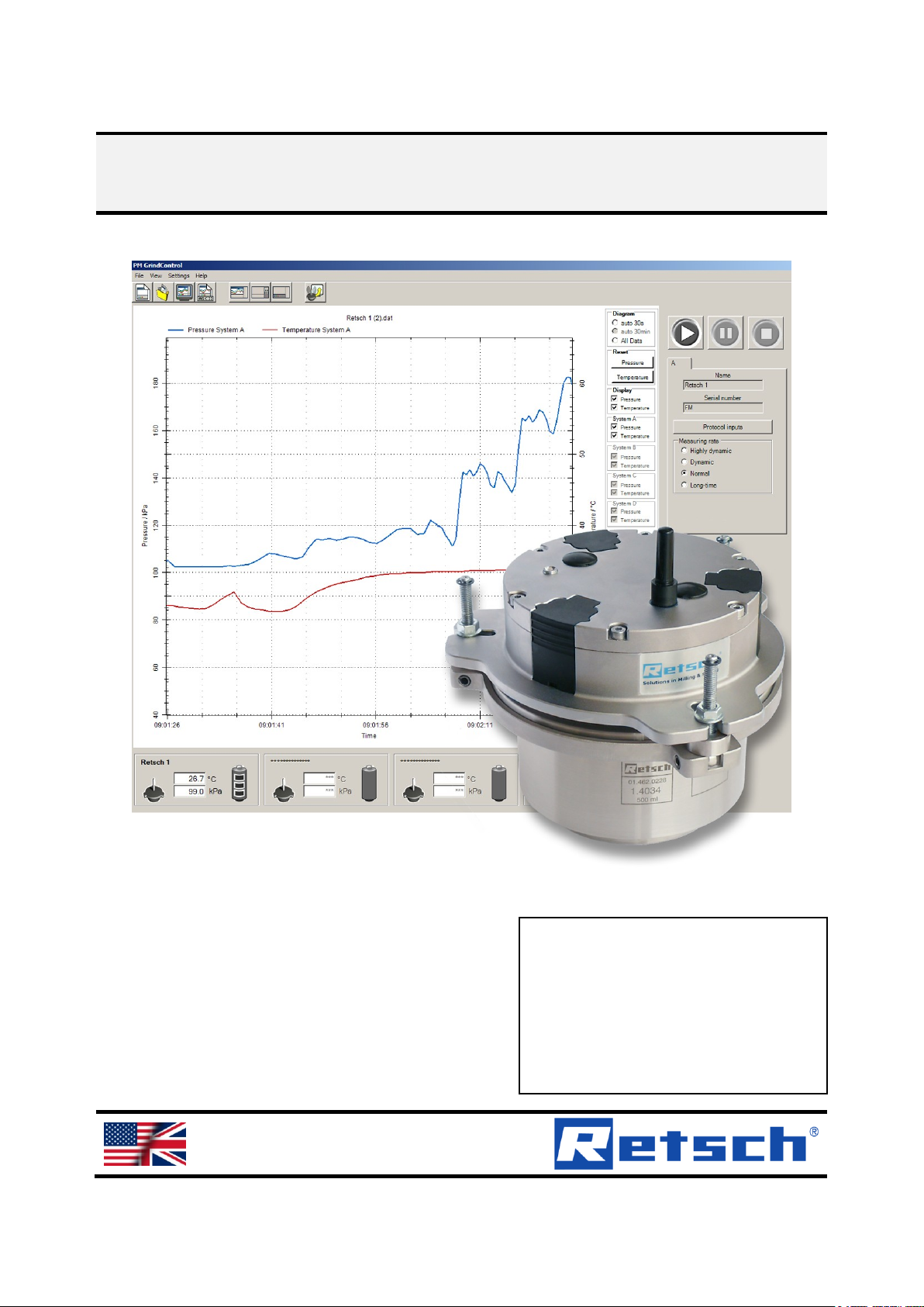
This wireless grinding jar cover and the PM GrindControl software serve to
continuously acquire the parameters pressure and temperature in a grinding jar.
The measured values read by the sensors located in the grinding jar cover are
transmitted wirelessly to a receiver system in the PC.
The temperature sensor is thermally separate from the grinding jar cover and
measures only the gas temperature in the grinding chamber. As a result, even
rapid or slight changes in temperature are registered.
Pos: 4.1 /00020 BDA Software/20005 PM GC Kapitelsam mlung/- - - - S eitenumbruc h - - - - @ 0\mod _12088576884 13_0.doc @ 3 37 @ @ 1
The transmitted data is displayed and stored in the software. For every
measurement, the values measured are stored in a file (dat-file) and are then
available for extensive evaluations.
The wireless grinding jar cover permits the use of the system in the PM 100 and
PM400.
Essentially, the following steps are necessary for using the PM GrindControl
software to monitor the temperature and the pressure in the grinding jar:
1. Definition of a measurement task
2. Integration of the measurement systems involved
3. Execution of the measurement
4. Evaluation of the measurement data
The evaluation can be conducted at a separate time from the measurement, i.e.
the raw data can be inputted again later and evaluated. The raw data contains all
the settings and protocol inputs stored in the measurement task.
7
Page 8
Technical Data
Monitor the temperature of the measurement unit inside the wireless grinding
jar cover at regular intervals to avoid damage to the measurement
electronics.
Screw the clamping screws on the clamping ring tight!
Maximum internal pressures of 5.0 bar are only permissible where there is
sufficient initial tension on the clamping ring.
Pos: 4.2 /00020 BDA Software/20005 PM GC Kapitelsam mlung/Überschrif ten/1. Überschrif ten/1 Technis che Daten @ 0\ mod_120 8870877356_9. doc @ 436 @ @ 1
3 Technical Data
Pos: 4.3 /00020 BDA Software/20005 PM GC Kapitelsam mlung/Überschrif ten/1.1 Überschri ften/11 Betrie bsbedingung en @ 0\mo d_12093889492 88_9.doc @ 656 @ @ 1
3.1 Operating Conditions
Pos: 4.4 /00020 BDA Software/20005 PM GC Kapitelsam mlung/Überschrif ten/1.1.1 Übersc hriften/111 T emperaturbereich @ 0\mo d_12093889810 03_9.doc @ 66 2 @ @ 1
3.1.1 Temperature Range
Pos: 4.5 /00020 BDA Software/20005 PM GC Kapitelsa mmlung/0005 T echnische Dat en/Modul Temp eraturbereich @ 0\mod_12106 68712505_9.d oc @ 935 @ @ 1
The temperature range is determined by the max. permissible temperature inside
the wireless grinding jar cover (measurement electronics) of 70°C.
An additional sensor measures the temperature of the measurement unit inside the
wireless grinding jar cover. On exceeding 70°C, a warning is outputted on the
screen.
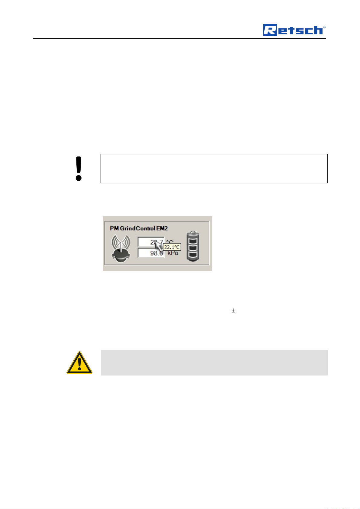
When you move the mouse cursor over the text box of the grinding jar, the
momentary temperature inside the wireless jar cover is displayed as a small tool tip
beside the mouse cursor. (See image: Temperature inside the wireless grinding jar
cover)
Fig. 1: Temperature inside the wireless grinding jar cover
Measurement Resolution of the Temperature Measurement : 0.1 °C
Pos: 4.6 /00020 BDA Software/20005 PM GC Kapitelsam mlung/Überschrif ten/1.1.1 Übersc hriften/111 Dr uckbereiche @ 0\mod_12 09389035861 _9.doc @ 668 @ @ 1
Accuracy of the Temperature Measurement: 1%
3.1.2 Pressure ranges
Pos: 4.7 /00020 BDA Software/20005 PM GC Kapitelsam mlung/0005 Tec hnische Daten/M odul Druckb ereich @ 0\ mod_121066871 3068_9.doc @ 942 @ @ 1
– Maximum permissible pressure range
Pos: 4.8 /00020 BDA Software/20005 PM GC Kapitelsam mlung/Warnhinw eise/Modul Sp annschrauben d es Spannring es fest anziehe n! II @ 0\m od_12227783 13010_9.doc @ 26 96 @ @ 1
Pos: 4.9 /00020 BDA Software/20005 PM GC Kapitelsam mlung/Überschrif ten/1.1.1 Übersc hriften/111 Dr ehzahlbereich @ 0\mod _120938907178 2_9.doc @ 674 @ @ 1
inside the grinding beaker: up to 5.0 bar (500 kPa)
3.1.3 Rotational speed range
Pos: 4.10 /00020 BDA Software/20005 PMGC Kapitelsa mmlung/0005 T echnische Daten/M odul Drehza hlbereich @ 0 \mod_12106 68713599_9.doc @ 949 @ @ 1
Rotational speed range: corresponds to the maximum rotational speeds of the PM
Pos: 4.11 /00020 BDA Software/20005 PMGC Kapitelsa mmlung/Überschri ften/1.1.1 Übersc hriften/111 S ender Reichw eite @ 0\ mod_1209389149 595_9.doc @ 686 @ @ 1
100 or PM 400 respectively
3.1.4 Transmitter range
Pos: 4.12 /00020 BDA Software/20005 PMGC Kapitelsa mmlung/0005 T echnische Daten/M odul Sender R eichweite @ 0\mod_121 0668715647_ 9.doc @ 977 @ @ 1
Pos: 4.13 /00020 BDA Software/20005 PMGC Kapitelsa mmlung/Übersc hriften/1.1.1 Üb erschriften/1 11 Betriebszeit @ 0\mod_120 9389101579_ 9.doc @ 680 @ @ 1
Transmitter range: approx. 15 m in buildings
3.1.5 Operating Time
Pos: 4.14 /00020 BDA Software/20005 PMGC Kapitelsa mmlung/0005 T echnische Daten/M odul Betrie bszeit @ 0\ mod_1210669318 768_9.doc @ 984 @ @ 1
8
Page 9

Technical Data
Operating time with full battery charge:
– highly dynamic measuring rate (200 Hz) - 40h
Pos: 5.1 /00020 BDA Software/20005 PM GC Kapitelsam mlung/Überschrif ten/1. Überschrif ten/1 Transp ort und Pfleg e @ 0\mod_ 1213010453912 _9.doc @ 1587 @ @ 1
Pos: 5.2 /00020 BDA Software/20005 PM GC Kapitelsam mlung/- - - - S eitenumbruc h - - - - @ 0\mod _12088576884 13_0.doc @ 3 37 @ @ 1
– long-time measuring rate (0.2 Hz) - 80h
9
Page 10

Technical Data
Caution – Damage to electronic components!
Do not clean the radio grinding jar cover under running water.
Pos: 5.3 /00020 BDA Software/20005 PM GC Kapitelsam mlung/Überschrif ten/1.1 Übersc hriften/11 Tr ansport und Lager ung @ 0\ mod_1216808117 898_9.doc @ 2072 @ @ 1
3.2 Transport and Storage
Pos: 5.4 /00020 BDA Software/20005 PM GC Kapitelsam mlung/0006 Kapit el Transport und Lieferumf ang/Modul Transp ort und Lageru ng @ 0\mo d_121680807 6180_9.doc @ 20 78 @ @ 1
3.2.1 Packaging
The packaging has been adapted to the mode of transport. It complies with the
generally applicable packaging guidelines.
Please retain the packaging for the duration of the warranty period because
returning in unsuitable packaging in the event of a complaint can jeopardize your
warranty claims.
3.2.2 Transport
Do not subject the PM GrindControl to impacts, jolts or vibrations during
transportation as this can damage the electronic and mechanical components.
3.2.3 Temperature Fluctuations
Where temperature fluctuates greatly (during shipment by air, for instance), protect
the PM GrindControl from condensation. The electronic components could
Pos: 5.5 /00020 BDA Software/20005 PM GC Kapitelsam mlung/Überschrif ten/1.1 Übersc hriften/11 Pfl egehinweise und Lagerung @ 0\mod_12173 17546169_9. doc @ 2150 @ @ 1
otherwise be damaged.
3.3 Care Instructions and Storage
Pos: 5.6 /00020 BDA Software/20005 PM GC Kapitelsam mlung/0006 Kapit el Transport und Lieferu mfang/Modul Pfleg e der Deckelgr undplatten @ 0\mod_1214 826413589_9.doc @ 1849 @ @ 1
The two cover baseplates are made of hardened stainless steel (1.4034).
Hardened steel has a lower chromium content and so it does not form any oxide
protective layer. Therefore, it distinguishes itself not by its corrosion resistance, but
by its greater hardness.
We therefore use a special oil to protect these grinding tools. Please remove the oil
before using it the first time; water and detergent are enough for this purpose.
Please dry the grinding tool well.
After the grinding operations, the grinding tools must be cleaned in as dry a state
as possible. However, if they are extremely dirty, they can be cleaned with a damp
cloth and some household detergent. It is important to ensure sufficient drying.
If the grinding tools are to be stored for a long time, we recommend the use of a
corrosion protection oil. If corrosion occurs nonetheless, it can be removed with
household scouring agents.
Also recommendable for long-time storage is to store the parts in the
accompanying VCE bags. (blue plastic bags).
Pos: 6.1 /00020 BDA Software/20005 PM GC Kapitelsam mlung/- - - - S eitenumbruc h - - - - @ 0\mod _12088576884 13_0.doc @ 3 37 @ @ 1
10
Page 11
The First Start
Read all chapters in this operating manual!
This description of the first activation of a wireless grinding jar cover does not
replace the need to read the operating instructions. Read the other chapters in this
manual too.
Please also read and observe the operating instructions for your planetary ball mill!
Do not pull the Telegesis (ZigBee) USB Stick out of the USB port as long as
the PM GrindControl software is active.
If the PM GrindControl software does not find the USB wireless unit (Telegesis),
you must connect the USB-stick manually once again. This requires the following
steps:
• Confirm the warning with OK.
(the PM GrindControl software starts)
• In program, PM GrindControl prodram select
Settings > Options > .
• Click on the Connect Again button
The measurement tasks must be saved to a local drive.
Pos: 6.2 /00020 BDA Software/20005 PM GC Kapitelsam mlung/Überschrif ten/1. Überschrif ten/1 Der erst e Start @ 0\ mod_120885 4281759_9.doc @ 324 @ @ 1
Der
4 The First Start
Pos: 6.3 /00020 BDA Software/20005 PM GC Kapitelsam mlung/Überschrif ten/1.1 Ü berschriften/11 V ollständiger Progr amm-Ablauf bis zur ersten Me ssung @ 0\ mod_1218549 278088_9.doc @ 2270 @ @ 1
4.1 Complete Program Sequence up to First Measurement
Pos: 6.4 /00020 BDA Software/20005 PM GC Kapitelsam mlung/0005 Der erste Start/Mo dul Der erste St art @ 0\mod _1209020476 978_9.doc @ 60 0 @ @ 1
The following sequence presents only the steps necessary for the first activation
and the test to see if the wireless grinding jar cover is functioning perfectly.
1. First, charge the three storage batteries completely using the charging
adapter in the accompanying charger. Read the chapter on OPERATING
INSTRUCTIONS POWERLINE 5 LCD beforehand
2. Follow the instructions in the Software Installation chapter and install the
USB driver for the ZigBee USB – wireless unit, the USB driver for the TGETRXn USB port and the PM GrindControl software.
3. Start the PM GrindControl software.
4. Insert the 3 fully charged batteries 1 into the wireless grinding jar.
The status indicator lamp starts to flash red and then glows a steady red.
Execute the following command in the PM GrindControl software::
5. Menu File Measurement task, new
6. Assign a new name to the first measurement task and save the file to a local
drive (e.g. C:\).
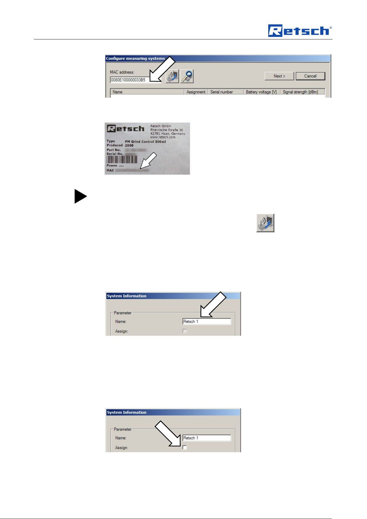
The Configure Measurement Systems program window is displayed.
7. Go to the MAC address filed and enter your grinding jar’s MAC address
number sequence.
11
Page 12
The First Start
After 15 minutes without assignment to a measurement task, the wireless
grinding jar cover switches off. If the status indicator lamp is not glowing red
any longer, take out one of the batteries and then put it back in again.
Fig. 2: Enter into the MAC address field.
You will find the MAC address on the cover page of your operating manual:
Fig. 3: MAC address
8. Click on the button Add measurement system..
Once the system corresponding to the MAC address has been found,
9. confirm with the OK button.
The status indicator lamp now glows green.
The System Information program window is displayed.
10. In the Name field, enter a name for the wireless grinding jar cover.
Fig. 4: Name field
11. After clicking on the Accept button,
12. you can end the procedure by clicking on the Close button.
The changed name is the name that is stored in the measurement system. On
connecting the next time, the measurement system will identify itself with this new
name.
13. Double-click to open the active system and click on the Assign field
Fig. 5: Assign active system to the measurement.
12
Page 13
The First Start
This adds the wireless grinding jar cover to the current measurement task as one
of the four possible measurement systems.
14. After clicking on the Accept button, you can end the procedure by clicking
on the Close button.
15. Now, click on the Continue button in the Assign measurement systems
program window.
In the Measurement Task window, you can input a remark for the measurement
task.
16. Click on the Continue button.
17. In the measurement file window, input a name for the first measurement of
the measurement task.
In the measurement file window, you can also input the operator and a remark for
the measurement.
18. You can end the creation of the measurement task with the Finish button.
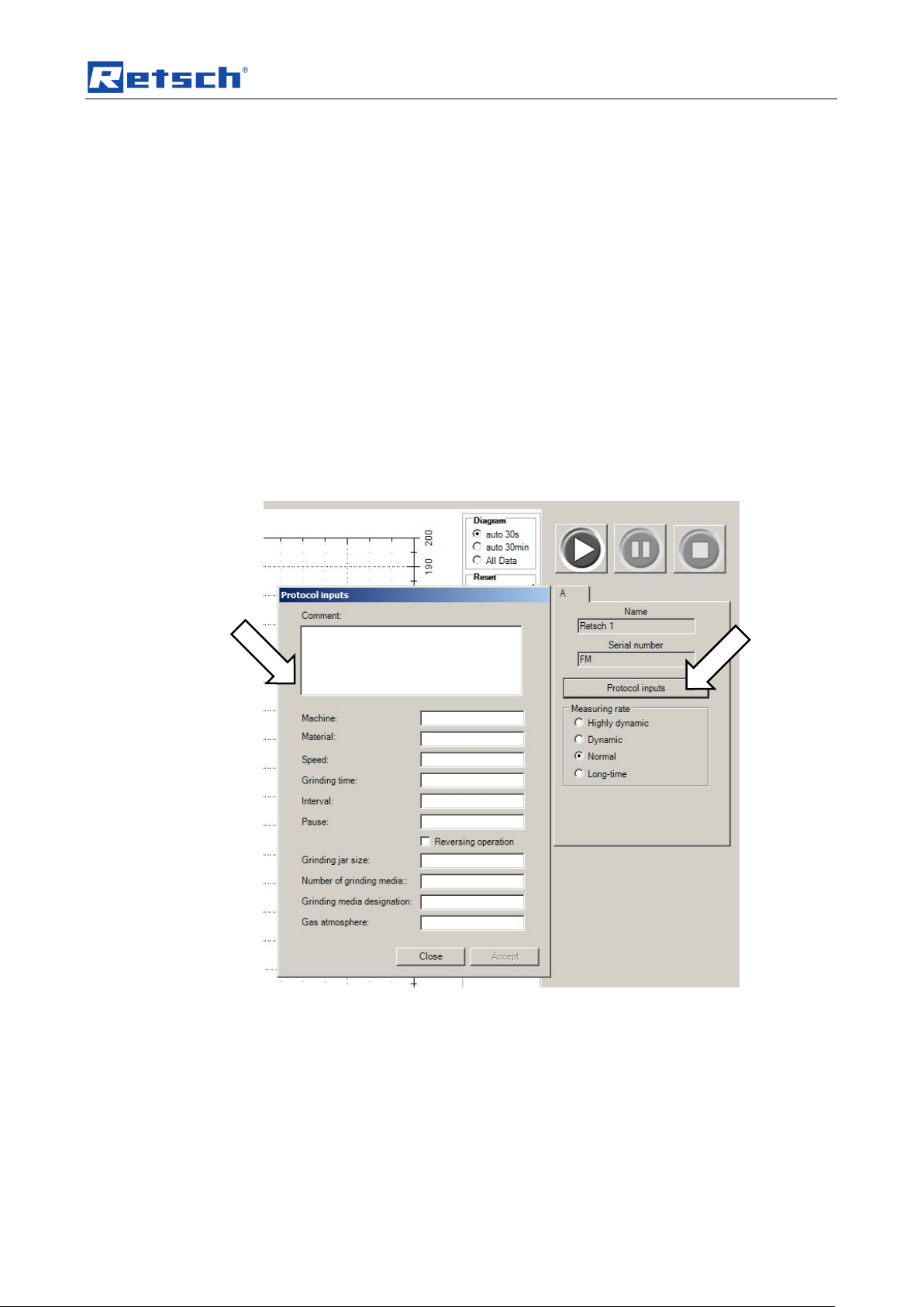
19. In the program window, in the Run Settings area, click on the protocol
inputs button.
Fig. 6: Protocol Inputs
20. After making these inputs, you can store the data with the Accept button
21. With the Close button, you are taken back to the program window.
22. Start the measurement with the Start button.
13
Page 14

The First Start
Pos: 7.1 /00020 BDA Software/20005 PM GC Kapitelsa mmlung/- - - - S eitenumbruc h - - - - @ 0\mod _12088576884 13_0.doc @ 3 37 @ @ 1
Fig. 7: Start - Pause - Stop
14
Page 15

Software
Do not pull the Telegesis (ZigBee) USB Stick out of the USB port as long as
the PM GrindControl software is active.
After the software for the Telegesis USB device has been installed, the
installation for the TG-ETRXn USB port follows automatically.
Pos: 7.2 /00020 BDA Software/20005 PM GC Kapitelsam mlung/Überschrif ten/1. Überschrif ten/1 Softw are @ 0\mod_ 12088711013 24_9.doc @ 4 48 @ @ 1
5 Software
Pos: 7.3 /00020 BDA Software/20005 PM GC Kapitelsam mlung/Überschrif ten/1.1 Überschri ften/11 Syste m-Vorrauss etzungen @ 0\ mod_1209389 491118_9.doc @ 711 @ @ 1
5.1 System Requirements
Pos: 7.4 /00020 BDA Software/20005 PM GC Kapitelsam mlung/0006 Software/Modul System- Vorr aussetzungen @ 0\mod_12100 73353541_9.d oc @ 790 @ @ 1
• Windows XP SP II and Windows Vista
• USB port (Version 1.1 or 2.0)
• The user must have local administrator rights.
• All energy saving functions on the PC system must be turned off.
• No screen saver with password input may be turned on.
• No programs that consume additional resources may be active.
Pos: 7.5 /00020 BDA Software/20005 PM GC Kapitelsam mlung/Überschrif ten/1.1 Ü berschriften/11 S oftware - Installa tionen @ 0\m od_12149247 91889_9.doc @ 1 924 @ @ 1
• Use a CPU with at least two cores (dual-core CPU)
5.2 Software Installations
Pos: 7.6 /00020 BDA Software/20005 PM GC Kapitelsam mlung/Überschrif ten/1.1.1 Übersc hriften/111 Ins tallation d er USB - Treib er @ 0\mod_1 214924749688_9. doc @ 1918 @ @ 1
5.2.1 Installing the USB Drivers
Pos: 7.7 /00020 BDA Software/20005 PM GC Kapitelsam mlung/0006 Soft ware/Modul Install ation USB Trei ber @ 0\m od_12100733 74165_9.doc @ 796 @ @ 1
Before you can install the software for PM GrindControl, the driver software of the
ZigBee USB wireless unit must be installed:
• Insert the installation CD included in the scope of supply into the CD ROM
drive in your PC.
• Insert the ZigBee USB wireless unit (Telegesis) into a free USB port on
your PC. And follow the installation instructions
1. “Wizard for searching for new hardware”
• Select "Yes, only this time"
2. “Wizard for searching for new hardware” window
• Select "Automatically install software (recommended)" and click on
<Continue>.
3. "Hardware Installation" window
• In the following windows warning, select "Continue installation"
1. "Wizard for searching for new hardware" window
• Select "Yes, only this time"
2. "Wizard for searching for new hardware" window
• Select "Automatically install software (recommended)" and click on
<Continue>
3. “Hardware Installation” window
Pos: 7.8 /00020 BDA Software/20005 PM GC Kapitelsa mmlung/Überschrif ten/1.1.1 Ü berschriften/11 1 Installation d er Software PM Grin dControl @ 0\mod_12149 24611772_9.d oc @ 1905 @ @ 1
• At the following Windows safety instruction select "Continue installation"
15
Page 16

Software
If you followed the instructions from chapter "The first Start", you can
proceed to point 4 of the corresponding chapter.
Reading in data after a measurement
The measurement data in the PM GrindControl software can only be viewed if the
originally created data structure has not been changed.
The file for the measurement task (.afg) and its folder must be stored in the same
folder.
File ending
Meaning
.mms
measurement system file
.tvl
temperature and voltage logfile
.dat
(measurement) data
5.2.2 Installation of the PM GrindControl Software
Pos: 7.9 /00020 BDA Software/20005 PM GC Kapitelsam mlung/0006 Soft ware/Modul Ins tallation der Sof tware PM Gri ndControl @ 0\ mod_12149 24249492_9.doc @ 1893 @ @ 1
• Start the setup.exe from the accompanying installation-CD-ROM and follow
the instructions that appear.
• Check with Windows Update whether important updates for .Net Framework
are available.
• Start the PM GrindControl software.
Pos: 7.10 /00020 BDA Software/20005 PMGC Kapitelsa mmlung/Überschri ften/1.1 Übersc hriften/11 Dat eisystem @ 0\ mod_12108 39584446_9.doc @ 1000 @ @ 1
5.3 File System
Pos: 7.11 /00020 BDA Software/20005 PMGC Kapitelsa mmlung/0006 Sof tware/Modul D ateisyste m @ 0\mod_12 10073432117_9.d oc @ 808 @ @ 1
5.3.1 File Endings
For each new measurement task create a new folder with the standard Windows
functions. This folder may be located only on the local computer system and not in
the network.
When a new measurement task is created, a new folder will be set up
automatically for the measurement data and a measurement file (.afg) created.
This file contains information on the measurement task, the measurement systems
involved and a list of the measurements carried out.
For every new measurement, the software generates a new folder (in the
measurement task folder). This folder has the name of the current measurement
and is numbered serially by the software. It contains the data record of the
measurement systems involved. Once a file exceeds a certain size, it is divided.
The PM GrindControl software uses the following file endings:
These files are in the measurement task folder and may not be deleted or
processed.
16
Page 17

Software
Folder:
c:\Measurement files
File:
Measurement_task_A.afg
File:
Measurement_task_B.afg
File:
Measurement_task....afg
Folder:
Measurement task
Folder:
Measurement
File:
Measurement_1.data
File:
Measurement_1_1.dat
Folder:
Measurement_2
File:
Measurement_2.dat
File:
Measurement_2_1.da
Folder:
Measurement_n
File:
Measurement_n.dat
File:
Measurement_n_1.da
Folder:
Measurement_task_B
Folder:
Measurement_task...
The folder for the measurement files must be on
a local data medium. It is not possible to move it
to other data carriers.
Once the file reaches a
certain size – e.g. during
continuous measurements the measurement data file is
split.
Pos: 7.12 /00020 BDA Software/20005 PMGC Kapitelsa mmlung/- - - - Seitenumbr uch - - - - @ 0\ mod_1208857688 413_0.doc @ 337 @ @ 1
Fig. 8: File Structure
17
Page 18

Software
Pos: 7.13 /00020 BDA Software/20005 PMGC Kapitelsa mmlung/Überschri ften/1.1 Übersc hriften/11 Soft ware Oberfläche @ 0\mod _12089363548 55_9.doc @ 4 80 @ @ 1
oInterface
5.4 Software Interface
Pos: 7.14 /00020 BDA Software/20005 PMGC Kapitelsa mmlung/0006 Sof tware/Modul Software Fun ktions-Bereiche @ 0\mod_12 18452830342_9 .doc @ 2206 @ @ 1
The program window for the PM GrindControl software breaks down into the
following function areas:
Fig. 9: Function areas for the PM GrindControl software
1 Menu and menu bar
2 Measurement Start - Pause - Stop
3 Diagram (graph box)
4 View menu to show the diagram
5 Protocol inputs and measurement rate setting
Pos: 7.15 /00020 BDA Software/20005 PMGC Kapitelsa mmlung/Überschri ften/1.1 Übersc hriften/11 M enü und Menüleist e @ 0\ mod_1218453559 911_9.doc @ 2212 @ @ 1
6 Status bar for the measurement systems
5.5 Menu and Menu Bar
Pos: 7.16 /00020 BDA Software/20005 PMGC Kapitelsa mmlung/0006 Sof tware/Modul M enü und Me nüleiste @ 0\ mod_1218523 903340_9.doc @ 2250 @ @ 1
Fig. 11: Menu bar
18
Page 19

Software
The measurement tasks must be saved to a local drive.
5.5.1 Menu File - Measurement task, new
Use this command to create a new empty measurement task and at the same time
end the current measurement task.
Using standard Windows functions, create a new folder for each new measurement
task. This folder may only be stored on the local computer system and not in the
network .
When creating a new measurement task, a new folder is created automatically for
the measurement data and a measurement file (.afg). This file contains information
on the measurement task, the measurement systems involved and a list of the
measurements carried out.
For each new measurement, the software generates a new folder in the
measurement task folder. This folder has the name of the current measurement
and is numbered consecutively by the software. It contains the data record of the
participating measurement systems. Once a file exceeds a certain size, it is
divided.
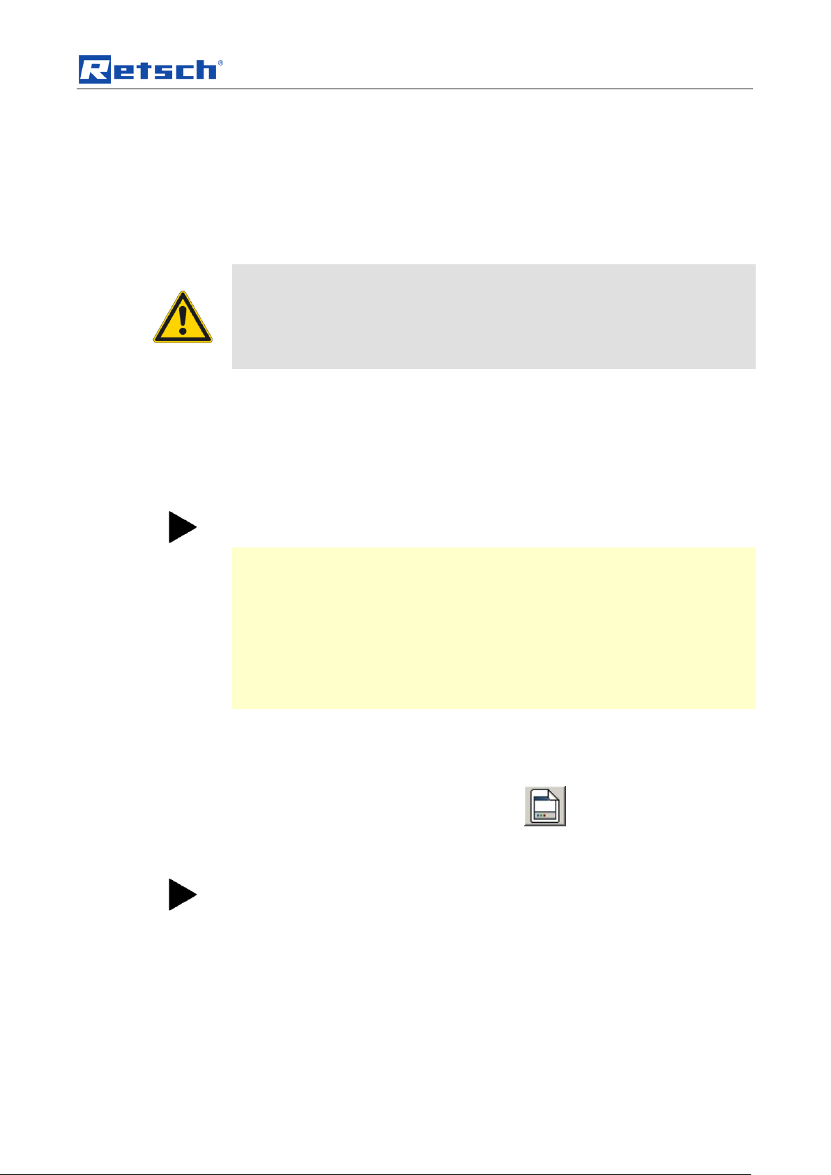
Alternatively, you can also use the following button.
Fig. 12: Button Measurement task, new
5.5.1.1 Steps for Creating a New Measurement Task
0. Once you click on the symbol or the command, the “Configure measurement
task” window appears. Assign a new name to the first measurement task
and save the file to a local drive (e.g. C:\).
The Configure Measuring Systems program window appears. If you wish to add a
new measuring system, follow steps 1. to 6.
1. Enter your grinding jar’s MAC address number sequence into the MAC
address field in the Configure Measuring Systems program window.
Fig. 13: Enter into the MAC address field
You will find the MAC address on the cover page of your operating manual:
Fig. 14: MAC Address
19
Page 20

Software
After 15 minutes without assignment to a measurement task, the wireless
grinding jar cover switches off. If the status indicator lamp is not glowing red
any longer, take out one of the batteries and then put it back in again.
2. Click on the Add measurement system button.
Once the system that corresponds to the MAC address has been found,
3. confirm with the OK button.
The status indicator lamp now glows green.
The “System Information” program window is displayed.
4. In the Name field, enter a name for the wireless grinding jar cover.
Fig. 15: Name field
5. After clicking on the Accept button,
6. you can end the procedure by clicking on the Close button.
The changed name is the name that is stored in the measurement system. On
connecting the next time, the measurement system will identify itself with this new
name.
7. If one or more measuring systems are logged in with the MAC address
already, these are displayed in the “Configure Measuring Systems” program
window:
Inactive Systems:
The measuring system is switched off or is outside the transmitter range.
Active Systems:
The measuring system can be added to the measurement task.
If you switch on a measuring system at a later point in time or bring it into the
transmitter range, this is not automatically displayed in the list of active systems.
With the Search for Known Measuring Systems button you can start a new
search for measuring systems.
Fig. 10: Search for Known Measuring Systems button
8. Open the active system by double-clicking on it and then click on the Assign
field.
20
Page 21

Software
Fig. 11: Assign the active system to the measurement
This adds the wireless grinding jar cover as one of the four possible measurement
systems for the current measurement task.
9. After clicking on the Accept button, you can end the procedure by clicking on
the Close button.
10. Now click on the Continue button in the Configure Measuring Systems
program window.
In the “Measurement Task” window, you can input a remark for the measurement
task.
11. Click on the Continue button.
12. in the “Measurement File” a name must be inputted for the first
measurement of the measurement task.
You can also input the operator and a remark for the measurement in the
“Measurement File” window.
13. You can end the creation of the measurement task by clicking on the Finish
button.
5.5.1.2 Menu File - Open Measurement Task
Use this command to open an existing measurement task. Another
measurement will be added.
Alternatively, you can also use the following button.
Fig. 12: Add New Measurement File to a Measurement Task button
Once you click on this symbol or the command, the “Open” window opens.
1. Select the measurement task to which you wish to add another
measurement and click on Open.
The "Search for Assigned Measuring Systems" opens and you can see the
list of the inactive systems.
If you switch on a measuring system at a later point in time or bring it into the
transmitter range, this is not automatically displayed in the list of active systems.
You can use the Search for Known Measuring Systems button to start a new
search for measuring systems.
Fig. 13: “Search for Known Measuring Systems” button
If you double-click on the active measuring systems, information on these systems
will be displayed.
2. Click on the Continue button.
The measurement task window opens and displays which measuring
systems are involved in the new measurement.
3. Click on the Continue button.
The Measurement File window opens.
21
Page 22

Software
Reading in data after a measurement
The measurement data in the PM GrindControl software can only be viewed if the
originally created data structure has not been changed.
The measurement task file (.afg) and its folder must be saved in the same folder.
End Program
The program can only be closed with the Menu File End command. For that
reason the program does not have the customary window symbols used in
Windows.
4. Select a file in the "Existing Measurement Files" list. This accepts the
protocol inputs from the corresponding measurement.
5. Enter a tick into the Add Counter checkbox. This inserts a counter after
the file name or updates an existing counter.
6. Click on the Finish button.
5.5.1.3 Menu File - Close Measurement Task
This command closes and saves an opened and an active measurement task
and the active measurement.
5.5.1.4 Menu File - Open Measurement Data
Viewing the RunFiles in a measurement task
Alternatively, you can also use the following button.
Fig. 20: Show Existing Measurement Data button
5.5.1.5 Menu File - Export Measurement Data
Exports the data in an opened RunFile into an ASCII file.
Alternatively, you can also use the following button.
Fig. 21: Export measuring data button
5.5.1.6 Menu File - End
Use this command to end the program.
Any information that has not been stored already is saved now and all program
processes are ended.
5.5.2 Menu View
In the View menu item you will find the following entries:
• diagram
• measurement setting
• status bar
22
Page 23

Software
• tool bar
Fig. 22: PM GrindControl Software function areas
5.5.2.1 Menu View - Diagram
Activates or deactivates the display of the measurement diagram.
Item numbers [3]+[4] in the "Function Areas of the PM GrindControl software"
figure.
Alternatively, you can also use the following button.
Fig. 23: Show Diagram button
5.5.2.2 Menu View - Measurement Settings
Activates or deactivates the display of the measurement settings and
measurement Start - Pause - Stop.
Item numbers [2]+[5] in the "Function Areas of the PM GrindControl Software"
figure.
Alternatively, you can also use the following buttons.
Fig. 24: Show diagram button
5.5.2.3 Menu View - Status Bar
Activates or deactivates the status bar display.
5.5.2.4 Menu View - Tool bar
Item number [6] in the "Function Areas of the PM GrindControl Software"
figure.
Alternatively, you can also use the following button.
Fig. 23: Status Bar Display button
Activates or deactivates the display of the tool bar.
23
Page 24

Software
Item number [1] in the "Function Areas of the PM GrindControl Software"
figure.
5.5.3 Menu Settings
In the Settings menu item you will find the following entries:
• Measuring Systems Management
• Options...
5.5.3.1 Menu Settings - Measuring Systems Management
Opens the “Measuring Systems Management” window.
5.5.3.2 Menu Settings - Options
Opens the “Options” window.
5.5.4 Menu Help
You will find the following entries in the Help menu item:
• on the PM GrindControl
• User guide
5.5.5 Menu View
Pos: 7.17 /00020 BDA Software/20005 PMGC Kapitelsa mmlung/0006 Sof tware/Modul Protokollei ngaben @ 0\mod _1219392571 439_9.doc @ 22 90 @ @ 1
In the View menu item you will find the following entries:
• diagram
• measurement setting
• status bar
• tool bar
24
Page 25

Software
41
42
43
45
47
49
44
46
48
50
40
51
Fig. 14: Program window for protocol inputs
The protocol details are saved in the .afg file.
You can save the following parameters:
40 Comments
41 Material
42 Machine
43 Speed
44 Grinding time
45 Interval
46 Pause
47 Reversing operation
48 Grinding jar size
49 Number of grinding media
50 Grinding media designation
51 Gas atmosphere
25
Page 26

Software
34
33
31
30
32
35
Pos: 7.18 /00020 BDA Software/20005 PMGC Kapitelsa mmlung/Überschri ften/1.1 Übersc hriften/11 Statusleiste der Me sssysteme @ 0\mod_12 18453801705_9 .doc @ 2242 @ @ 1
5.6 Status Bar for the Measuring Systems
Pos: 7.19 /00020 BDA Software/20005 PMGC Kapitelsa mmlung/0006 Sof tware/Modul Statusleiste der Messsyste me @ 0\mod_1 219303118953_9. doc @ 2280 @ @ 1
Fig. 15: Status Bar for the Measuring Systems
30 Name of the measuring system
31 Temperature inside the grinding jar
32 Battery level status
33 Transmission status of the measuring system
34 Pressure inside the grinding jar
35 Empty fields for more measuring systems
When you move the mouse cursor over the text box of the grinding jar, the current
temperature inside the wireless jar cover is displayed as a tool tip. (see image)
When you move the mouse cursor over the battery symbol the voltage in the
measuring system is displayed as a tool tip (see image).
Pos: 7.20 /00020 BDA Software/20005 PMGC Kapitelsa mmlung/Überschri ften/1.1 Übersc hriften/11 Erlä uterung der Ico ns und Symbol e @ 0\mod _1208859219 384_9.doc @ 35 7 @ @ 1
Er
Fig. 16: Temperature inside the wireless grinding jar cover
5.7 Explanation of the Icons and Symbols
Pos: 7.21 /00020 BDA Software/20005 PMGC Kapitelsa mmlung/0006 Sof tware/Modul Software Buttons @ 0\mod_ 121500896823 0_9.doc @ 19 30 @ @ 1
Fig. 29: Program menu item symbols
Fig. 30: Create new measurement task
Fig. 31: Add new measurement file to a measurement task.
26
Page 27

Software
Fig. 32: Show existing measurement data
Fig. 33: Export measurement data
Fig. 34: Display diagram
Fig. 35: Display measurement settings
Fig. 36: Display status bar
Pos: 7.22 /00020 BDA Software/20005 PMGC Kapitelsa mmlung/Überschri ften/1.1 Übersc hriften/11 M essraten @ 0\ mod_12143127 45260_9.doc @ 1756 @ @ 1
Measuring Rates
Fig. 37: Measuring systems management
5.8 Measuring Rates
Pos: 7.23 /00020 BDA Software/20005 PMGC Kapitelsa mmlung/0006 Sof tware/Modul M essraten @ 0\mod_12143 11304050_9.doc @ 1750 @ @ 1
Highly Dynamic Measuring Rate (200 Hz) - 40h
Long-time Measuring Rate (0.2 Hz) - 80h
Consider which measuring rate is best for your application. If possible, select a low
Pos: 8.1 /00020 BDA Software/20005 PM GC Kapitelsam mlung/- - - - S eitenumbruc h - - - - @ 0\mod _12088576884 13_0.doc @ 3 37 @ @ 1
measuring rate (normal). This reduces the volume of data.
27
Page 28

Wireless Grinding Jar Cover
Pos: 8.2 /00020 BDA Software/20005 PM GC Kapitelsam mlung/Überschrif ten/1. Überschrif ten/1 Fun k-Mahlbecher deckel @ 0\mod_ 12089600300 49_9.doc @ 5 81 @ @ 1
6 Wireless Grinding Jar Cover
Pos: 8.3 /00020 BDA Software/20005 PM GC Kapitelsam mlung/Überschrif ten/1.1 Überschri ften/11 Fun k-Mahlbech erdeckel Kom ponenten @ 0\ mod_120903640 1882_9.doc @ 61 6 @ @ 1
6.1 Wireless Grinding Jar Cover Components
Pos: 8.4 /00020 BDA Software/20005 PM GC Kapitelsam mlung/Funk M ahlbecherdeckel/M odul Funk-M ahlbecher deckel Kompone nten @ 0\mod_ 12090246142 78_9.doc @ 610 @ @ 1
Fig. 38: Wireless grinding jar cover, top view
1. • Battery
2. • Gassing valves / or cover caps
3. • Status indicator lamp
4. • Wireless antenna
5. • Cover plate
6. • MAC wireless address
7. • Grinding jar cover
Pos: 8.5 /00020 BDA Software/20005 PM GC Kapitelsam mlung/Überschrif ten/1.1 Übersc hriften/11 Ei nsetzen der Akkus @ 0\mod_ 120903905503 7_9.doc @ 64 0 @ @ 1
28
Fig. 39: Wireless grinding jar cover, bottom view
14 Opening for the deaeration valves (cover baseplate with venting holes)
25 Temperature sensor
20 Air ducts for measuring pressure
Page 29

Wireless Grinding Jar Cover
Batteries may not be disposed of with the household trash. Bring the used batteries
to your dealer or to the battery collection point.
6.2 Inserting the Batteries
Pos: 8.6 /00020 BDA Software/20005 PM GC Kapitelsam mlung/Fun k Mahlbecherdec kel/Modul Einsetz en der Akkus @ 0\mod_12 08959898706_9.d oc @ 568 @ @ 1
Fig. 17: Inserting the batteries
Pos: 8.7 /00020 BDA Software/20005 PM GC Kapitelsam mlung/Überschrif ten/1.1 Übersc hriften/11 PM GrindControl ausschalten @ 0\ mod_121663 4480360_9. doc @ 2026 @ @ 1
6.3 Turning Off the GrindControl
Pos: 8.8 /00020 BDA Software/20005 PM GC Kapitelsam mlung/Funk M ahlbecherdeckel/M odul PM Gri ndControl a usschalten @ 0\ mod_121662841 0547_9.doc @ 2020 @ @ 1
– Remove one of the storage batteries to switch the PM GrindControl off.
– If necessary, insert the battery the other way around to store it. This keeps
the PM GrindControl turned off.
Pos: 8.9 /00020 BDA Software/20005 PM GC Kapitelsam mlung/Überschrif ten/1.1 Überschri ften/11 LED Anzeige am Fu nk-Mahlbec herdeckel @ 0\ mod_121489 6046933_9.doc @ 1886 @ @ 1
Fig. 18: Turning off the PM GrindControl
6.4 LED Display on the Wireless Grinding jar Cover
Pos: 8.10 /00020 BDA Software/20005 PMGC Kapitelsa mmlung/Funk Ma hlbecherdec kel/Modul LED Anzeig e am Fun k-Mahlbech erdeckel @ 0\mo d_121489596 8549_9.doc @ 1 880 @ @ 1
6.4.1 Status indications
– Red (switched on and initialized)
– Green (connected)
– Red flashing (initializing flickering)
29
Page 30

Wireless Grinding Jar Cover
When using the gassing function, make sure the gassing channels are free.
20
– Green flashing (measurement was started
Pos: 8.11 /00020 BDA Software/20005 PMGC Kapitelsa mmlung/Überschri ften/1.1 Übersc hriften/11 Reinigu ng der Luftka näle des Druck sensors @ 0\mod_1216 716068719_9.d oc @ 2046 @ @ 1
and measurement values are being transmitted)
6.5 Cleaning the Air Duct in the Pressure Sensor
Pos: 8.12 /00020 BDA Software/20005 PMGC Kapitelsa mmlung/Funk Ma hlbecherdec kel/Modul Reinigu ng der Luftkan äle Drucksens or @ 0\mo d_121671588134 5_9.doc @ 20 40 @ @ 1
The air ducts (20) in the pressure sensor can be cleaned with a vacuum cleaner
too if they get dirty.
Pos: 8.13 /00020 BDA Software/20005 PMGC Kapitelsa mmlung/Überschri ften/1.1 Übersc hriften/11 Beg asungs-Fun ktion @ 0\ mod_120893649958 7_9.doc @ 49 3 @ @ 1
Fig. 19: Air ducts
6.6 Gassing Function
Pos: 8.14 /00020 BDA Software/20005 PMGC Kapitelsa mmlung/Funk Ma hlbecherdec kel/Modul die Beg asungsfunktion @ 0\mod_ 12148249678 09_9.doc @ 1 830 @ @ 1
To enable the PM GrindControl to be used for grinding in a controlled atmosphere
also, the kit contains a cover baseplate with venting holes for the gassing function
(centring plate with venting holes).
Pos: 8.15 /00020 BDA Software/20005 PMGC Kapitelsa mmlung/- - - - Seitenumbr uch - - - - @ 0\ mod_1208857688 413_0.doc @ 337 @ @ 1
The venting holes can also be cleaned with a vacuum cleaner too if they get dirty.
30
Page 31

Wireless Grinding Jar Cover
12
2
12
11
13
14 4 7
2 9 14
Pos: 8.16 /00020 BDA Software/20005 PMGC Kapitelsa mmlung/Überschri ften/1.1 Übersc hriften/11 Austa uschen d er Deckelgrun dplatte @ 0\mod _12100721110 61_9.doc @ 7 84 @ @ 1
6.7 Exchanging the Cover Baseplate
Pos: 8.17 /00020 BDA Software/20005 PMGC Kapitelsa mmlung/Funk Ma hlbecherdec kel/Modul Austa usch der Deckelg rundplatte @ 0\ mod_1214 313457521_9. doc @ 1780 @ @ 1
Fig. 43: Assembly of the cover baseplate and the de-aeration parts
The following steps are required to replace the pre-assembled standard cover
baseplate (centring plate standard) with the cover baseplate which has venting
holes for the gassing function (centring plate with ventilation holes):
Required tools:
13-mm open-jaw wrench
Hexagon socket screw key 2.5 mm
31
Page 32

Wireless Grinding Jar Cover
14
8
10
• Unscrew the antenna (4).
• Remove the two black caps from the venting holes (9).
• Remove the three screws (13) on the pre-assembled standard cover
baseplate and lift the plate up from the cover housing.
• Place the cover baseplate with the venting holes (12) in front of you with the
recess for the filter fleece (8) pointing upwards.
• Caution! When inserting the two de-aerating tubes (14), the surface
with which the tubes are fitted (flat) (10) must point downwards. After
tightening, this flat fits on the cover baseplate.
Fig. 44: Position of the de-aerating tubes
• Screw the two de-aerating tubes (14), as described, from the top downwards
into the cover baseplate (12) and tighten it with a 13-mm open-jaw wrench.
• Before assembly, check the state and the correct position of the seals and
the filter fleece.
• Now, insert the cover baseplate with the de-aerating tubes mounted on it into
the cover housing; when doing so, pay attention to the position of the filter
fleece (11).
• Next, tighten the cover baseplate with the three screws (13).
• Screw the two de-aerating valves (2) into the venting holes (9) and tighten
them with a 13-mm open-jaw wrench.
Pos: 8.18 /00020 BDA Software/20005 PMGC Kapitelsa mmlung/Überschri ften/1.1 Üb erschriften/11 Filt ervlies Wechs el @ 0\mod_1 20938979977 4_9.doc @ 742 @ @ 1
• Screw the antenna (4) onto the grinding jar cover.
6.8 Changing the Filter Fleece
Pos: 8.19 /00020 BDA Software/20005 PMGC Kapitelsa mmlung/Funk Ma hlbecherdec kel/Modul Wechs el des Filtervlie ses @ 0\ mod_1214313335 584_9.doc @ 1774 @ @ 1
Depending on the application and the period of use, it may be necessary to replace
the filter fleece that is located in the grinding jar cover.
Replace the filter fleece if it is very dirty.
6.9 Replacing the Filter Fleece When Using the Standard Cover Baseplate
Tools required:
Hexagon socket screw key 2.5 mm
• Unscrew the antenna (4).
• Remove the three screws (13), on the pre-assembled standard cover
baseplate and lift the plate up from the cover housing.
32
Page 33

Wireless Grinding Jar Cover
The wireless grinding jar cover cannot be used in the PM 200.
Fig. 13: Replacing the filter fleece
• Replace the filter fleece.
• Before assembly, check the state and the correct position of the seals and
the filter fleece.
• Now, insert the cover baseplate back in the cover housing; when doing so,
pay attention to the position of the filter fleece (11).
• Next, tighten the cover baseplate with the three screws (13).
• Screw the antenna (4) onto the grinding jar cover. Tauschen Sie das
Filtervlies aus.
6.10 Replacing the Filter Fleece When Using the Gassing Function
Tools required:
13-mm open-jaw wrench
Hexagon socket screw key 2.5 mm:
• Unscrew the antenna (4).
• Remove the two de-aeration valves (2), using a 13-mm open-jaw wrench.
• Remove the three screws (13) on the pre-assembled standard cover
baseplate and lift the plate up from the cover housing.
• Replace the filter fleece (see fig. Replacing the filter fleece)
• Before assembly, check the state and the correct position of the seals and
the filter fleece.
• Now, insert the cover baseplate with the mounted de-aeration tubes in the
cover housing und when doing so, pay attention to the position of the filter
fleece (11).
• Next, tighten the cover baseplate with the three screws (13).
• Screw the two de-aeration valves (2) into the venting holes (9) and tighten
them with a 13-mm open-jaw wrench.
• Screw the antenna (4) onto the grinding jar cover. Schrauben Sie die
Pos: 8.20 /00020 BDA Software/20005 PMGC Kapitelsa mmlung/Überschri ften/1.1 Übersc hriften/11 M ahlbecher schließ en @ 0\ mod_12148276892 98_9.doc @ 18 61 @ @ 1
Antenne (4) ab.
6.11 Clamping the Grinding jar with the Clamping Ring
Pos: 8.21 /00020 BDA Software/20005 PMGC Kapitelsa mmlung/Warn hinweise/Hinweis nicht in PM2 00 verwendbar @ 0\mod_12 10056716286_9.d oc @ 766 @ @ 1
33
Page 34

Wireless Grinding Jar Cover
The wireless grinding jar cover cannot be used in the PM 200.
Comply with the operating instructions for your ball mill too.
This document only has instructions for the use of the PM GrindControl. Safe
handling of the planetary ball mill is a precondition for the use of the PM
GrindControl.
Risk of the grinding jar being hurled out!
Make sure before starting the machine that the grinding jar is clamped in position.
With due consideration to the degree of risk presented by the particular material
you are grinding, please take appropriate precautions to ensure that there will not
be any danger to people.
21
27
23
24
22
26
Pos: 8.22 /00020 BDA Software/20005 PMGC Kapitelsa mmlung/Funk Ma hlbecherd eckel/Modul Mahlb echer mit Spannri ng verschließ en @ 0\mo d_12148275973 15_9.doc @ 18 55 @ @ 1
Fig. 46::Position of the clamping ring
For the measurement of the grinding jar’s inner pressure to work correctly, the
grinding jar cover must be braced with the clamping ring, which is included in the
scope of supply.
• The spacer (26) must be between the cover lug (21) and the clamping ring.
• When bracing it, it is necessary to align one of the cover lugs (21) with the
labelling areas (24) in order to ensure that the catching hole (27) in the
grinding jar can engage with the catching pin (23).
34
Page 35

Wireless Grinding Jar Cover
Risk of burning your hands.
It is essential to wear safety gloves when removing or opening the heated grinding
jar.
Tighten the camping screws on the clamping ring securely!
Tighten the clamping screws on the clamping ring securely.
Only then are inside pressures up to a max. 5.5 bar permissible.
Pos: 8.23 /00020 BDA Software/20005 PMGC Kapitelsa mmlung/Überschri ften/1.1 Übersc hriften/11 Nass vermahlungen mit leicht e ntzündlichen M aterialien @ 0\mod_1216805 932680_9.doc @ 2060 @ @ 1
6.12 Wet Grinding with Highly Flammable Materials
Pos: 8.24 /00020 BDA Software/20005 PMGC Kapitelsa mmlung/Funk Ma hlbecherdec kel/Modul Nass vermahlunge n mit leicht entz ündlichen Mat erialien @ 0\ mod_1216805897 993_9.doc @ 2066 @ @ 1
Wet grinding using easily inflammable materials is admissible providing certain
precautions are taken.
When using highly flammable materials as grinding aids, such as for example,
hexane, isopropanol, ethanol, benzene and suchlike, it must be assumed that the
inside of the grinding jar is classifiable as zone 0 with a continually present
explosive mixture.
It must therefore be ensured that the explosive vapours that arise during the
grinding process, in particular because of the heating that occurs then, cannot
escape from the clamped-in grinding jars or reach areas that contain the required
ignition energy.
We therefore urgently recommend that before using such solvents the operator
(employer) of the planetary ball mill should assess the existing hazards and draw
up a coherent explosion protection policy, taking account of local conditions and, if
necessary, providing written definitions of supplementary organisational measures
in an explosion protection document.
In the EU, this procedure is regulated by articles 118 and 118a of EC Directive
89/391/EEC.
Please observe comparable regulations in countries outside the EU.
For this purpose, assume the following prerequisites for the PM100/200:
• Only type “C” grinding jars are admissible for wet grinding with highly
flammable materials.
• When selecting solvents, the O-rings’ resistance must be taken into account.
The following are therefore permissible: alcohol (apart from methanol and
ethanol), isopropanol, diisopropylether.
• Once the grinding jars have been filled, seal them with the clamping rings
included in the scope of supply.
• Please note that depending on the size of the grinding jar, the ball filling,
speed and grinding time, the grinding jar can by all means reach a
temperature of over 100°C.
• The PM100 and PM200 are fitted with a fan which extracts only directly from
the grinding chamber. The extraction volume per hour is more than 20 times
the volume of the grinding chamber. The fan has a standstill monitor with an
acoustic alarm.
• The air stream produced by the fan during grinding must be conducted to an
extractor.
35
Page 36

Telegesis (ZigBee) USB stick
Do not pull the Telegesis (ZigBee) USB Stick out of the USB port as long as
the PM GrindControl software is active.
• Before removing the grinding bowl, make sure that the clamping ring is
sitting securely.
• Only remove the grinding bowl with the closing device. Before opening it, let
Pos: 9.1 /00020 BDA Software/20005 PM GC Kapitelsam mlung/Überschrif ten/1. Üb erschriften/1 USB Stick Teleg esis (ZigBee) @ 0\mod_12093 89458882_9.doc @ 705 @ @ 1
it cool down and make sure it is in a safe position (suction equipment).•
7 Telegesis (ZigBee) USB stick
Pos: 9.2 /00020 BDA Software/20005 PM GC Kapitelsam mlung/Warnhinw eise/Modul War nhinweis Ziehe n Sie den US B Stick Telegesis (Z igBe e) nicht aus de m USB-Port @ 0\ mod_12184487 52202_9.doc @ 2200 @ @ 1
Pos: 9.3 /00020 BDA Software/20005 PM GC Kapitelsam mlung/Überschrif ten/1.1 Überschri ften/11 Syste m-Vorrauss etzungen @ 0\ mod_1209389 491118_9.doc @ 711 @ @ 1
7.1 System Requirements
Pos: 9.4 /00020 BDA Software/20005 PM GC Kapitelsam mlung/USB Stic k Telegesis (ZigB ee)/Modul US B Stick technisch e Vorraussetzu ngen @ 0\mod_12144 65966515_9.doc @ 1820 @ @ 1
Your PC must meet the following technical requirements to allow the use of the
Telegesis (ZigBee) USB stick:
– Windows XP or Windows Vista
Pos: 9.5 /00020 BDA Software/20005 PM GC Kapitelsam mlung/Überschrif ten/1.1 Überschri ften/11 Tech nische Daten @ 0\mod_ 1213703629615 _9.doc @ 1660 @ @ 1
7.2 Technical Data
Pos: 9.6 /00020 BDA Software/20005 PM GC Kapitelsam mlung/USB Stic k Telegesis (ZigB ee)/Modul Zig bee technische D aten @ 0 \mod_12101520 50859_9.d oc @ 900 @ @ 1
Pos: 10 /00010 Bedienungsanleitungen K apitelsammlunge n/------- Seitenumbruch ----------- @ 0\mod_12223 44373758_0.doc @ 2386 @ @ 1
– USB 2.0 (1.1)
Frequency band: 2.4GHz ISM band
Transmission rate: 250kbit/s over the air data rate – NB: actual usable data
throughput with ZigBee® is about 20kbps
Transmission power: Typically 17dBm (50mW) output power
Damping: High sensitivity of -97dBm Typ (at 1% packet error rate)
36
Page 37

Operating Instructions for Powerline 5 LCD
Charge new batteries completely before using them for the first time. This
extends the service life of your batteries.
!
Pos: 11.1 /00020 BDA Software/20005 PMGC Kapitelsa mmlung/Überschri ften/1. Überschri ften/1 Bedie nungsanleitung Powerline 5 LCD @ 0\ mod_12184469157 78_9.doc @ 21 94 @ @ 1
8 Operating Instructions for Powerline 5 LCD
Pos: 11.2 /00020 BDA Software/20005 PMGC Kapitelsa mmlung/Ladeg erät/Modul Vorsic ht Neue Batterie n Laden @ 0\ mod_12155 94705254_9. doc @ 1996 @ @ 1
Pos: 11.3 /00020 BDA Software/20005 PMGC Kapitelsa mmlung/Ladeg erät/Modul Batteri en Laden @ 0 \mod_1215 590180106_9.d oc @ 1990 @ @ 1
Fig. New batteries must be charged completely first before they are inserted.
Pos: 11.4 /00020 BDA Software/20005 PMGC Kapitelsa mmlung/Ladeg erät/Modul Eins etzen Ladeadapt er @ 0\mo d_12090388983 22_9.doc @ 62 8 @ @ 1
Pos: 11.5 /00020 BDA Software/20005 PMGC Kapitelsa mmlung/- - - - Seitenumbr uch - - - - @ 0\ mod_1208857688 413_0.doc @ 337 @ @ 1
Fig. 47: Inserting the charging adapter
37
Page 38

Operating Instructions for Powerline 5 LCD
Read the operating instructions carefully before commissioning the
appliance!
Warning – General dangers!
• The appliance may only be operated in closed, dry rooms.
• To eliminate the danger of fire or of an electrical shock, the appliance must be
protected from moisture and rain.
• Please ensure that the ventilation slits are free so that the appliance can work
perfectly.
• Do not operate the appliance if the mains plug or housing is damaged.
• Do not open or modify the appliance.
• Have repairs carried out only by an authorized dealer.
• Keep out of reach of children.
• Do not run the appliance unsupervised.
• After use, disconnect the appliance from the mains supply.
• Pull out the mains plug before doing any cleaning or maintenance work.
Only the special batteries supplied by Retsch may be used in the
POWERLINE 5 LCD charger!
CAUTION:
Insert only Nickel/Cadmium or Nickel/Metal hydride storage batteries; there
is a risk of explosion with other batteries!
Alkaline batteries or other primary batteries may not be charged under any
circumstances
Never use force to open storage batteries or other kinds of batteries and
never throw them into a fire.
Pos: 11.6 /00020 BDA Software/20005 PMGC Kapitelsa mmlung/Ladeg erät/Modul Ladeg erät Bedienungsa nleitung @ 0\ mod_12143 18216209_9. doc @ 1798 @ @ 1
8.1 Safety Instructions
8.2 Using the Charger
8.3 Overview of the Charger Functioning
38
– Separate charging procedures for every battery
– Automatic commencement of charging once contact is established;
– Microcontroller-controlled charging and monitoring of the charging status
– Automatic switching over to trickle charging
– Pre-discharge possible;
Page 39

Operating Instructions for Powerline 5 LCD
– Status indication with indicator lamps and LCD
– Battery fault detection – faulty batteries are picked out and displayed.–
8.3.1 Indicator Lamps for Batteries (1)
Indicator glows red: charging
Indicator flashing red: battery faulty
Indicator glows yellow: discharging
Indicator glows green: battery charged / pulse retention charging
8.3.2 LCD Display (3)
In addition to the indicator lamps, the display gives information on the charging
state, the operating mode and the status of the inserted batteries (see drawing).
The operating mode (charging or discharging) is displayed alternatively.
Thereafter, for approx. 3 seconds, the charging status is displayed in 25 % steps.
“OK“ indicates the end of charging / trickle charging; “BAD“ indicates a faulty
battery.
8.3.3 Discharge key (4)
Pressing the discharge key (PRESS) for approx. 3 seconds starts the discharging
process.
8.4 Commissioning the Charger
Mains Operation:
Connect the power supply plug to the charger. Connect the power supply to the
mains supply.
Charging the special Retsch storage batteries:
The charging starts automatically when one or more batteries are inserted.
To insert the storage batteries, it is first necessary to insert the charging adapter:
Press the contact bridge (5) down and insert the cell into the charging
compartment.
The storage batteries do not have to be inserted at the same time because the
batteries charge independently of each other.
It is normal for the batteries to become hot while charging. Once charging is
complete, the batteries are supplied with trickle charging and can remain in the
charger till they are used.
Discharging:
To discharge the storage batteries, simply press the PRESS button (4) for approx.
3 seconds. Once the storage batteries have finished discharging, the appliance
automatically switches over to charging. It is possible to discharge some batteries
and simultaneously charge other batteries. When batteries are inserted into
unoccupied charging compartments after activated discharging, they are charged
and not discharged!
8.5 Maintenance and Care of the Charger
Pull out the mains plug before doing any maintenance and cleaning work. To
ensure that the appliance will work without problems, please keep the contacts in
the charging compartment free of dirt. Clean the appliance only with a dry cloth.
39
Page 40

Operating Instructions for Powerline 5 LCD
8.6 Environment Notice
By using rechargeable batteries and chargers, you can protect the environment
and save at the same time. Batteries should not be disposed of with the household
Pos: 11.7 /00020 BDA Software/20005 PMGC Kapitelsa mmlung/- - - - Seitenumbr uch - - - - @ 0\ mod_1208857688 413_0.doc @ 337 @ @ 1
waste. Bring used batteries to your dealer or to the battery collection point.
40
Page 41

Pos: 11.8 /00020 BDA Software/20005 PMGC Kapitelsa mmlung/Ladeg erät/Modul Ladeg erät Grafiken @ 0\mod_ 1214381853335_9 .doc @ 1810 @ @ 1
Operating Instructions for Powerline 5 LCD
Fig. 20: LCD display, charger
Fig. 21: Charger function elements and charging times
=== Ende der Liste für Textmarke Inhalt ===
41
Page 42

9 Index
A
Accuracy of the Temperature Measurement ........ 8
Active Systems ................................................... 20
Add Counter ........................................................ 22
ASCII................................................................... 22
B
Battery symbol .................................................... 26
C
Care Instructions and Storage ............................ 10
Changes ............................................................... 5
Changing the Filter Fleece.................................. 32
Charger Function Elements and Charging Times
........................................................................ 41
Clamping the Grinding jar with the Clamping Ring
........................................................................ 33
Cleaning the Air Duct in the Pressure Sensor .... 30
Close Measurement Task ................................... 22
Commissioning the Charger ............................... 39
Complete Program Sequence up to First
Measurement .................................................. 11
Configure Measurement task ............................. 19
Configure Measuring Systems ........................... 19
Confirmation ......................................................... 6
Copyright .............................................................. 5
Corrosion protection oil ....................................... 10
Corrosion resistance ........................................... 10
Cover Baseplate ................................................. 31
Cover page ......................................................... 19
D
Diagram .............................................................. 23
Discharge key ..................................................... 39
E
Explanation of the Icons and Symbols ............... 26
Export Measurement Data ................................. 22
Extreme Dirt ....................................................... 10
F
File Endings ....................................................... 16
File Structure ...................................................... 17
File System ........................................................ 16
First Activation ................................................... 11
First Measurement ............................................. 11
Folder ................................................................. 19
Function Areas ................................................... 18
G
Gassing Function ............................................... 30
Green ................................................................. 29
H
hardened stainless steel .................................... 10
Highly Dynamic .................................................. 27
Highly Dynamic Measuring Rate ....................... 27
I
Inactive Systems ................................................ 20
Indicator Lamps for Batteries ............................. 39
Inserting the Batteries ........................................ 29
Installation of the PM GrindControl Software .... 16
Installing the USB Drivers .................................. 15
L
LCD Display ....................................................... 39
LCD Display Charger ......................................... 41
LED Display on the Wireless Grinding jar Cover 29
Local Computer System..................................... 19
Long-time ........................................................... 27
Long-time Measuring Rate ................................ 27
End ...................................................................... 22
Environment Notice ............................................ 40
Exchanging the Cover Baseplate ....................... 31
Existing Measurement Files ............................... 22
42
M
Mains Operation ................................................. 39
Maintenance and Care of the Charger .............. 39
Page 43

Measurement Resolution of the Temperature
Measurement .................................................... 8
Measurement Settings ........................................ 23
Measurement task, new...................................... 19
Measuring Rates ................................................. 27
Measuring Systems Management ...................... 24
Menu and Menu Bar ........................................... 18
Menu file ............................................................. 18
Menu Help .......................................................... 24
Menu Settings ..................................................... 24
Menu View .......................................................... 22
Method of Operation ............................................. 7
N
Network ............................................................... 19
Notes on the Operating Manual ............................ 5
O
Open Measurement Data ................................... 22
Open Measurement Task ................................... 21
Operating Conditions ............................................ 8
Operating Instructions for Powerline 5 LCD ....... 37
Operating Time ..................................................... 8
Options................................................................ 24
Overview of the Charger Functioning ................. 38
oxide protective layer .......................................... 10
P
Pressure Ranges .................................................. 8
Program Processes ............................................ 22
Program Sequence ............................................. 11
S
Safety Instructions ............................................. 38
Search for Known Measuring Systems .............. 20
Software ............................................................. 15
Software Installations ......................................... 15
Software Interface .............................................. 18
Special Oil .......................................................... 10
Status Bar .......................................................... 23
Status Bar for the Measuring Systems .............. 25
Status indications ............................................... 29
Subsequent Switching-On of a Measuring System
....................................................................... 20
System Requirements.................................. 15, 36
T
Technical Data ..................................................... 8
Technical Data ................................................... 36
Telegesis (ZigBee) USB stick ............................ 36
Temperature range .............................................. 8
Temperature Range ............................................. 8
Temperature sensor ............................................. 7
The First Start .................................................... 11
Tool bar .............................................................. 23
Tool Tip .............................................................. 26
Transmitter range ................................................. 8
Transport and Storage ....................................... 10
Turning Off the GrindControl ............................. 29
U
Using the Charger .............................................. 38
Protocol Inputs .................................................... 22
R
Raw data ............................................................... 7
Red ..................................................................... 29
Replacing the Filter Fleece When Using the
Gassing Function ............................................ 33
Replacing the Filter Fleece When Using the
Standard Cover Baseplate ............................. 32
Rotational speed range......................................... 8
V
VCE Bags .......................................................... 10
Voltage in the Measuring System ...................... 26
W
Wet Grinding with Highly Flammable Materials . 35
Windows Window Symbols Suppressed ........... 22
Wireless Grinding Jar Cover .............................. 28
Wireless Grinding Jar Cover Components ........ 28
43
Page 44

Page 45

Page 46

Page 47

Page 48

Copyright
® Copyright by
Retsch GmbH
Haan, Retsch-Allee 1-5
D-42781 Haan
Federal Republic of Germany
 Loading...