

Page 1

Manual
Knife Mill GM 300
Translation
© Retsch GmbH, 42781 Haan, Retsch-Allee 1-5, Germany 12.11.2012 0006
Page 2

Copyright
© Copyright by
Retsch GmbH
Haan, Retsch-Allee 1-5
D-42781 Haan
Federal Republic of Germany
2
Page 3

1 Notes on the Operating Manual ............................................................................................................ 5
1.1 Explanations of the safety warnings .................................................................................................. 6
1.2 General safety instructions ................................................................................................................ 7
1.3 Repairs ............................................................................................................................................... 8
2 Confirmation ........................................................................................................................................... 9
3 Transport, scope of delivery, installation .......................................................................................... 10
3.1 Packaging ........................................................................................................................................ 10
3.2 Transport.......................................................................................................................................... 10
3.3 Temperature fluctuations and condensed water ............................................................................. 10
3.4 Conditions for the place of installation ............................................................................................. 10
3.5 Removing the transport safeguard .................................................................................................. 11
3.6 Installation of the machine ............................................................................................................... 11
3.7 Electrical connection ........................................................................................................................ 11
3.8 Type plate description ...................................................................................................................... 11
4 Technical data ....................................................................................................................................... 13
4.1 Use of the machine for the intended purpose.................................................................................. 13
4.2 Protective equipment ....................................................................................................................... 13
4.3 Emissions......................................................................................................................................... 14
4.4 Degree of protection ........................................................................................................................ 14
4.5 Drive output...................................................................................................................................... 15
4.6 Rated power .................................................................................................................................... 15
4.7 Rated voltage ................................................................................................................................... 15
4.8 Rotation speed ................................................................................................................................. 15
4.9 Dimensions and weight .................................................................................................................... 15
4.9.1 Height with Hood Cover Closed................................................................................................... 15
4.9.2 Height with Hood Cover Open ..................................................................................................... 15
4.9.3 Weight .......................................................................................................................................... 15
4.10 Required floor space ........................................................................................................................ 15
5 Operating the machine ........................................................................................................................ 16
5.1 Views of the Instrument ................................................................................................................... 16
5.2 Operating elements and displays .................................................................................................... 17
5.3 Overview table of the parts of the device ........................................................................................ 19
5.4 Switching On and Off ....................................................................................................................... 20
5.5 Opening and closing of the grinding chamber ................................................................................. 20
5.6 Handling the Knife ........................................................................................................................... 20
5.7 Inserting the grinding jar .................................................................................................................. 22
5.7.1 Grinding container - use with different materials ......................................................................... 24
5.8 Grinding Jar Lid Sealing Rings ........................................................................................................ 24
3
Page 4

5.9 Starting the grinding process ........................................................................................................... 25
5.10 Interrupting and continuing the grinding process ............................................................................ 25
5.11 Stopping the grinding process ......................................................................................................... 25
5.12 Menu structure ................................................................................................................................. 26
5.12.1 Setting Possibilities on the Display Menu ................................................................................ 26
5.13 Setting the grinding time .................................................................................................................. 28
5.14 Setting the Speed ............................................................................................................................ 28
5.15 Setting the Direction of Rotation ...................................................................................................... 29
5.16 Setting the interval ........................................................................................................................... 29
5.17 Emergency unlocking ...................................................................................................................... 29
6 Working instructions............................................................................................................................ 31
7 Fault messages ..................................................................................................................................... 31
8 Cleaning and service ........................................................................................................................... 32
9 Accessories .......................................................................................................................................... 34
10 Disposal ................................................................................................................................................. 35
11 Index ...................................................................................................................................................... 36
Appendix ............................................................................................................................... following pages
4
Page 5

Notes on the Operating Manual
1 Notes on the Operating Manual
This operating manual is a technical guide on how to operate the device safely and
it contains all the information required for the areas specified in the table of
contents. This technical documentation is a reference and instruction manual. The
individual chapters are complete in themselves.
Familiarity (of the respective target groups defined according to area) with the
relevant chapters is a precondition for the safe and appropriate use of the device.
This operating manual does not contain any repair instructions. If faults arise or
repairs are necessary, please contact your supplier or get in touch with Retsch
GmbH directly.
Application technology information relating to samples to be processed is not
included but can be read on the Internet on the respective device’s page at
www.retsch.com.
Changes
Subject to technical changes.
Copyright
Disclosure or reproduction of this documentation, use and disclosure of its contents
are only permitted with the express permission of Retsch GmbH.
Infringements will result in damage compensation liability.
5
Page 6
Notes on the Operating Manual
WARNING
Type of danger / personal injury
Source of danger
– Possible consequences if the dangers are not observed.
• Instructions on how the dangers are to be avoided.
WARNING
CAUTION
Type of danger / personal injury
Source of danger
– Possible consequences if the dangers are not observed.
• Instructions on how the dangers are to be avoided.
CAUTION
NOTICE
Nature of the property damage
Source of property damage
– Possible consequences if the instructions are not observed.
• Instructions on how the dangers are to be avoided.
1.1 Explanations of the safety warnings
In this Operating Manual we give you the following safety warnings
Serious injury may result from failing to heed these safety warnings. We give you
the following warnings and corresponding content.
We also use the following signal word box in the text or in the instructions on action
to be taken:
Moderate or mild injury may result from failing to heed these safety warnings.
We give you the following warnings and corresponding content.
We also use the following signal word box in the text or in the instructions on action
to be taken:
In the event of possible property damage we inform you with the word
“Instructions” and the corresponding content.
We also use the following signal word in the text or in the instructions on action to
be taken:
NOTICE
6
Page 7
Notes on the Operating Manual
CAUTION
Read the Operating Manual
Non-observance of these operating instructions
– The non-observance of these operating instructions can
result in personal injuries.
• Read the operating manual before using the device.
• We use the adjacent symbol to draw attention to the
necessity of knowing the contents of this operating
manual.
CAUTION
Changes to the machine
– Changes to the machine may lead to personal injury.
• Do not make any change to the machine and use spare parts and
accessories that have been approved by Retsch exclusively.
NOTICE
Changes to the machine
– The conformity declared by Retsch with the European Directives will lose
its validity.
– You lose all warranty claims.
• Do not make any change to the machine and use spare parts and
accessories that have been approved by Retsch exclusively.
1.2 General safety instructions
Target group : All persons concerned with the machine in any form
This machine is a modern, high performance product from Retsch GmbH and
complies with the state of the art. Operational safety is given if the machine is
handled for the intended purpose and attention is given to this technical
documentation.
You, as the owner/managing operator of the machine, must ensure that the people
entrusted with working on the machine:
• have noted and understood all the regulations regarding safety,
• are familiar before starting work with all the operating instructions and
specifications for the target group relevant for them,
• have easy access always to the technical documentation for this machine,
• and that new personnel before starting work on the machine are familiarised
with the safe handling of the machine and its use for its intended purpose,
either by verbal instructions from a competent person and/or by means of
this technical documentation.
Improper operation can result in personal injuries and material damage. You are
responsible for your own safety and that of your employees.
Make sure that no unauthorised person has access to the machine.
7
Page 8

Notes on the Operating Manual
The Retsch representative in your country
Your supplier
Retsch GmbH directly
Reperaturen
1.3 Repairs
This operating manual does not contain any repair instructions. For your own
safety, repairs may only be carried out by Retsch GmbH or an authorized
representative or by Retsch service engineers.
In that case please inform:
Your Service Address:
8
Page 9

Confirmation
I have read and taken note of the contents of all chapters in this operating
manual as well as all safety instructions and warnings.
User
Surname, first name (block letters)
Position in the company
Signature
Service technician or operator
Surname, first name (block letters)
Position in the company
Place, date and signature
Bestätigung
2 Confirmation
This operating manual contains essential instructions for operating and maintaining
the device which must be strictly observed. It is essential that they be read by the
operator and by the qualified staff responsible for the device before the device is
commissioned. This operating manual must be available and accessible at the
place of use at all times.
The user of the device herewith confirms to the managing operator (owner) that
(s)he has received sufficient instructions about the operation and maintenance of
the system. The user has received the operating manual, has read and taken note
of its contents and consequently has all the information required for safe operation
and is sufficiently familiar with the device.
As the owner/managing operator you should for your own protection have your
employees confirm that they have received the instructions about the operation of
the machine.
9
Page 10

Transport, scope of delivery, installation
NOTICE
Storage of packaging
– In the event of a complaint or return, your warranty claims may be
endangered if the packaging is inadequate or the machine has not been
secured correctly.
• Please keep the packaging for the duration of the warranty period.
NOTICE
Transport
– Mechanical or electronic components may be damaged.
• The machine may not be knocked, shaken or thrown during
transport.
NOTICE
Temperature fluctuations
The machine may be subject to strong temperature fluctuations during transport
(e.g. aircraft transport)
– The resultant condensed water may damage electronic components.
• Protect the machine from condensed water.
NOTICE
Ambient temperature
– Electronic and mechanical components may be damaged and the
performance data alter to an unknown extent.
• Do not exceed or fall below the permitted temperature range of the
machine (5°C to 40°C / ambient temperature).
3 Transport, scope of delivery, installation
3.1 Packaging
3.2 Transport
The packaging has been adapted to the mode of transport. It complies with the
generally applicable packaging guidelines.
3.3 Temperature fluctuations and condensed water
3.4 Conditions for the place of installation
Atmospheric humidity:
Maximum relative humidity 80% at temperatures up to 31°C, decreasing linearly up
10
to 50% relative humidity at 40°C
Page 11
Transport, scope of delivery, installation
NOTICE
Atmospheric humidity
– Electronic and mechanical components may be damaged and the
performance data alter to an unknown extent.
• Do not exceed the admissible range for atmospheric humidity.
NOTICE
Installation of the machine
– It must be possible to disconnet the machine from the mains at any time.
• Install the machine such that the connection for the mains cable is
easily accessible.
WARNING
1
2 3 4
5 6 7 8 9
10
11
12
14
13
3.5 Removing the transport safeguard
Remove the cardboard cross, which serves to protect the knives during transport),
from the inside of the grinding jar.
3.6 Installation of the machine
Installation height: maximum 2000 m above sea level
3.7 Electrical connection
When connecting the power cable to the mains supply, use an external fusethat
complies with the regulations applicable to the place of installation .
• Please check the type plate for details on the necessary voltage and
frequency for the device.
• Make sure the levels agree with the existing mains power supply.
• Use the supplied connection cable to connect the device to the mains power
supply.
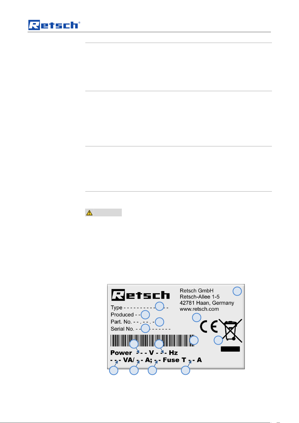
3.8 Type plate description
Fig. 1: Type plate lettering
11
Page 12

Transport, scope of delivery, installation
1 Device designation
2 Year of production
3 Part number
4 Serial number
5 Manufacturer’s address
6 CE marking
7 Disposal label
8 Bar code
9 Power version
10 Mains frequency
11 Capacity
12 Amperage
13 Number of fuses
14 Fuse type and fuse strength
In the case of questions please provide the device designation (1) or the part
number (3) and the serial number (4) of the device.
12
Page 13

Technical data
NOTICE
Area of use of the machine
– This machine is a laboratory machine designed for 8-hour single-shift
operation.
• This machine may not be used as a production machine nor is it
intended for continuous operation.
4 Technical data
4.1 Use of the machine for the intended purpose
Target group: Operators
Machine type designation: GM 300
The GRINDOMIX GM 300 laboratory knife mill serves to mill, homogenise and mix
soft to medium-hard, aqueous, fatty, fibrous and dry materials
within seconds
so that they will be suitable for analysis.
It can process sample volumes of up to 4.5 litres quickly and reproducibly.
The GRINDOMIX GM 300 is designed for quantities up to approx. 4500 ml, large
volume materials up to 1000 ml. The feed size is < 130 mm.
It is particularly engineered to cut up the following materials:
fish, meat, vegetables, cheese, fodder pellets, seeds, bacon, sausage, dry bakery
products and pasta, all products with high water, fat and fibrous content and similar
materials.
The GRINDOMIX GM 300 meets the special laboratory and analysis requirements
and in its range of performance it far outstrips that of commercially available
household mixers.
Our applications laboratory will be happy to give you more information.
Fast and gentle size reduction and homogenisation of food
Speed selectable from 500 - 4,000 rpm
Powerful 1.5 KW industrial motor
All parts which come in contact with the sample material are autoclaveable
Easy changing and cleaning of the grinding tools
Interval operation and reverse mode possible
Mode for preliminary size reduction and fine size reduction
Digital parameter preselection
10 parameter combinations can be stored
4.2 Protective equipment
Manual access into the GRINDOMIX GM300 grinding chamber is prevented by an
electromechanical locking device.
13
Page 14

Technical data
CAUTION
Damage to hearing
The level of noise can be high depending on the type of material,
the knife used, the speed set and the duration of the grinding
process.
- Noise that is excessive in terms of level and duration can cause
impaired or permanently damaged hearing.
• Ensure suitable sound-proofing measures or wear
hearing protection.
CAUTION
Possibility of acoustic signals not being heard
Loud grinding noises
- Acoustic alarms and voice communication might not be heard.
• Consider the volume of the grinding noise in relation to other
acoustic signals in the work environment. You may wish to use
additional visual signals.
The device can be started only if the housing cover is closed and can be opened
only if the motor has stopped completely.
The actual speed is displayed during operation.
The safety device checks that the grinding jar and cover are in place before the
grinding process can be started.
4.3 Emissions
If the speed deviates by more than 15 %, the device will switch off automatically.
Noise characteristics:
The noise is measured in conformance to DIN 45635-031-01-KL3.
The noise characteristics are influenced by the properties of the material being
ground.
Example 1):
Sound-power level LWA = 93.5 dB (A)
Workplace-related emissions level Lp Aeq = 78.7 dB (A)
Operating conditions:
Container = plastic container with cover
Grinding organ = stainless steel knives
Feed material = quartz sand
Feed volume = 2.5 l
Speed = 3000 min-1
4.4 Degree of protection
Grinding chamber and keyboard IP45
14
In the area of the ventilation slots IP20
Page 15

Technical data
4.5 Drive output
3-phase asynchronous motor with frequency converter
4.6 Rated power
Continuous duty 1.5 KW, peak performance 3 kW
4.7 Rated voltage
– 220 - 230 V 50 / 60Hz + 0,1Hz
4.8 Rotation speed
The knife speedcan be set in 100-rpm steps from 500 to 4000 rpm.
4.9 Dimensions and weight
4.9.1 Height with Hood Cover Closed
Height: 340 mm
Width: 440 mm
Depth: 440 mm
4.9.2 Height with Hood Cover Open
Height: 700 mm
Width: 440 mm
Depth: 430 mm
4.9.3 Weight
approx. 30 kg
4.10 Required floor space
440 mm x 440 mm; no safety margins required
15
Page 16

Operating the machine
B A C D E
F G H
I J O M A B N C L K NE
5 Operating the machine
5.1 Views of the Instrument
0
Fig. 2: Front view
Fig. 3: Rear view
16
Page 17

Operating the machine
P
Q E R S W
X
Fig. 4: Detailed views of housing
Fig. 5: Detail of grinding jar disassembly
5.2 Operating elements and displays
17
Page 18

Operating the machine
G
H I J
F
Fig. 6: Graphical View of the Control Panel
18
Page 19

Operating the machine
Element
Description
Function
A
Grinding jar cover
Closes the grinding chamber
B
Flap
Prevents interference with the grinding chamber
C
Grinding chamber
Accommodates the sample material
D
Knife
Grinds the sample material
E
Jar holder (base frame)
Accommodates the grinding jar
F
Display window
To check settings and operating conditions
G
Control knob
To adjust the device
H
START button
To start the grinding process
I
STOP button
To stop the grinding process
J
Button to open the flap
Releases the flap lock
K
Not assigned
No function
L
Serial port
Software update and service
M
On/off button
Disconnects device from the power supply
N
Housing fan
Cools the drive
O
Electrical connection
IEC connector
P
Tightening
Is held by the electromechanical interlock
Q
Seal of tightening
Prevents penetration of dirt
R
Cone dome
Seals the knife bearing
S
Bearing flange
Supports the knife shaft
W
Coupler
Connects bearing flange and drive
X
Centring ring
Guides the coupler
5.3 Overview table of the parts of the device
19
Page 20

Operating the machine
CAUTION
Injuries in the form of cuts
Sharp knife blades
– The knife blades are very sharp and if handled incorrectly, they can lead to
injuries in the form of cuts.
• Touch the knife only at the recessed grips.
• Do not reach into the grinding jar as long as sample material is
covering the knife.
• Only reach into the grinding jar if it is outside the mill.
• Before taking out the knife, remove the sample material until the
recessed grips are free. Use a scraper or shake off the material.
5.4 Switching On and Off
• Switch on the mill by pressing the ON/OFF switch (M) at the back.
When the GM300 is switched on for the first time, the language menu is displayed.
You can select your national language here by turning the operating knob (G).
Pressing this knob confirms the selection and the display shows “Open Lid”.
5.5 Opening and closing of the grinding chamber
• Press the (J) key.
The electromagnetic safety interlock opens and the flap can be folded back. The
grinding jar is now freely accessible.
NOTE
After the interruption or end of a grinding process, the flap must be opened once.
Closing the grinding chamber is only possible if the GM300 is connected to the
power supply and the main switch on the back of the device is switched on.
• Shut the housing lid (B) and press it downwards until the lid closure is
activated .
A sensor detects the closure of the housing lid and the motor-driven lid closure is
switched on. The housing lid is closed automatically.
5.6 Handling the Knife
NOTE
Insert the knife before feeding the material to be ground; otherwise, the
material to be cut up can settle between the knife and the driving shaft.
20
Page 21

Operating the machine
CAUTION
Fig. 7: Recessed grips on the knife
Fig. 8: Removing the knife– Fill level of the grinding jar
Note that the knife must be inserted before filling the grinding jar. The knife is
placed on the shaft and held by magnetic force .
The sealing lip (DL) of the V ring seal (V) must point downwards when inserted.
(See Fig. for knife assembly)
NOTICE
• Remove the knife after the grinding process.
• Do not leave the knife in the sample material!
• Clean the knife after grinding and then dry carefully.
If the bottom, bent blade of the knife is so deformed that it touches the inside of the
jar it must be replaced immediately.
21
Page 22

Operating the machine
CAUTION
CAUTION
Scalding/burns
Hot grinding jar
– Depending on the grinding process, the material being ground and
accordingly the grinding jar can become very hot.
• Wear appropriate protection always when touching the grinding jar if
it is hot.
1.
3.
2.
V
DL
Fig. 9: Inserting the sealing ring
Fig. 10: Preparing the knife and grinding jar, inserting the knife
NOTE
• Check the state of the V-ring seal (V) regularly.
– The bottom edge of the lip seal (DL) must be clean and smooth.
• Replace the V-ring seal when the lip seal is brittle, cracked, frayed or
damaged in order to prevent rust and damage to the cutter bearing.
(V-ring seal part number: 05.111.0243)
5.7 Inserting the grinding jar
When grinding with dry ice(CO2), give consideration to the quantity of dry ice used
and the volume of gas that will develop accordingly.
The grinding jar lids have varying ventilation characteristics and can be pressed
upwards by the large volume of the generated gas.
1. Assemble the knife.
22
Page 23

Operating the machine
CAUTION
CAUTION
SL
2. Use the face spanner (SL) to mount the knife dome and the bearing flange in
the grinding jar. (see diagram below)
NOTE
Before inserting the grinding jar, it is essential to ensure that the bearing flange
and the knife dome are positioned securely. If necessary, tighten the bearing
flange with the face spanner (SL).
Fig. 11: Use a face spanner to remove the knife dome
3. Put the knife in the grinding jar on the knife dome and let the knife lock into
place.
4. Fill the grinding jar with the sample to be ground. Depending on the material,
the filling level may be as high as up to 2 cm under the edge of jar.
Note that some materials may increase knife wear, damage the knife or
damage the jar.
The knife must not be reground.
If the sample to be ground is dry, use a steel grinding jar. Dry grinding stock
can become very hot and damage the PVC grinding jar.
5. Put the lid onto the grinding jar, with one or two sealing rings depending on the
material.
6. Insert the grinding jar with knife, grinding stock and lid into the device.
7. Close the flap on the device.
8. Make sure the grinding jar engages with the correspondingly shaped
projections.
NOTE
Protect the grinding jar from continuous exposure to sunlight or UV irradiation.
The PC jar is not infinitely UV-resistant.
23
Page 24

Operating the machine
4.
6.
5.
Fig. 12: Inserting the grinding jar and closing the device.
5.7.1 Grinding container - use with different materials
The material properties specified refer to samples from the main area of
applications: food or animal fodder
The plastic grinding jar is less suitable for dry, tough or fibrous samples.
Stainless steel is recommended for these samples as well as all others from the
specified field of applications.
5.8 Grinding Jar Lid Sealing Rings
The grinding jar cover is supplied as standard with a sealing ring inserted in the
upper groove.
When grinding dustyor very watery sample material, you can insert the second
supplied sealing ring into the grinding jar cover. This prevents sample material
escaping.
24
Page 25

Operating the machine
Fig. 13: Use of one or two sealing rings
NOTE
Thin fluid samples should be started at a low speed. Increase the speed gradually.
The maximum speed for liquid samples may not exceed 2,500 revolutions per
minute.
5.9 Starting the grinding process
Set the grinding parameters you wish to have.
Insert the grinding jar with the material to be ground, the knife and the lid.
Close the flap until the electromechanical safety interlock is closed.
Press the START (H) key.
5.10 Interrupting and continuing the grinding process
• Press the STOP (I) key.
The grinding process is interrupted or stopped.
5.11 Stopping the grinding process
Interrupting the Grinding Process (Pause)
• Press the STOP key (I) once.
The grinding process is interrupted.
Stopping the Grinding Process (End)
25
Page 26

Operating the machine
Direction of rotation (knife beating)
Direction of rotation (knife cutting)
Acoustic alarm on
Acoustic alarm off
Service required
• Press the STOP key (I) twice.
The grinding process is stopped (end).
The grinding parameters are reset to the previously set or stored values.
5.12 Menu structure
This device offers new, very user-friendly prompting. All relevant data can be
entered into or called up on a graphic display with one-button operation. The menu
instructions are multi-lingual.
5.12.1 Setting Possibilities on the Display Menu
Please refer also to the chapter on menu structure for information on using the
setting possibilities on the display, as described in the following.
The selection bar in the display is operated as follows:
Turning function I)
• Turn the setting knob to reach the individual menu items. The selected
menu items are marked by the dark selection bar.
Turning function II)
• Turn the setting knob to alter the numbers and decisions in the menu
items.
Pressing I)
• Press the setting knob to open the selected menu items.
Pressing II)
• Press the setting knob to confirm the settings.
Pressing III)
• Press and hold the setting knob to return to the start screen (Level 1).
26
Page 27

Operating the machine
1st level
2nd level
3rd level
4th level
5th level
6th level
1
Manual operation
Sequeces 01 to 10
(Press knob and turn to the
left)
Grinding program 01 tos 10
(Turn knob to the right)
2
Grinding duration
Grinding duration
[1sec. to 3 minutes (m:ss) ]
3
Speed
500 to 4000 revolutions per
minute
Direction of rotation
Right / left
4
Interval
Interval grinding duration
mm:ss
Reverse direction of
rotation
Set interval mm:ss
Back
6
Program mode
Use parameter
Change program
Delete program
Back
7
Menu
Settings
Automatic opening
On / off
Warning tone
On / off
Service
Operating hours
Total operating
hours
xxxxx.xx.xx
hh:mm:ss
Operating software
Operating
software
Version: xyz
Update
Yes/cancel
Start
software
update?
Yes/cancel
Back
Back
Display
Contrast
Adjust
Brightness
Adjust
Language
Select
Back
Date 01.04.03
Set
Time
12:05:00
Set
Back
27
Page 28

Operating the machine
P01
Sequences 01
P01
P01+P02
Sequences 02
P02
P01+P02+P03
Sequences 03
P03
P01+P02+P03+P04
Sequences 04
P04
P01+P02+P03+P04+P05
Sequences 05
P05
P01+P02+P03+P04+P05+P06
Sequences 06
P06
P01+P02+P03+P04+P05+P06+P07
Sequences 07
P07
P01+P02+P03+P04+P05+P06+P07+P08
Sequences 08
P08
P01+P02+P03+P04+P05+P06+P07+P08+P09
Sequences 09
P09
P01+P02+P03+P04+P05+P06+P07+P08+P09+P10
Sequences 10
P10
Sequences
Program
5.13 Setting the grinding time
• Turn the rotary knob until you reach the grinding time menu item.
The selected menu item is marked by the dark selection bar.
• 1. Press the rotary knob to set the minutes.
• Turn the rotary knob until you reach the desired grinding time in minutes.
• 2. Press the rotary knob to set the seconds.
• Turn the rotary knob until you reach the desired grinding time in seconds.
• 3. Press the rotary knob in order to return to the main menu.
5.14 Setting the Speed
• Turn the rotary knob until you reach the speed menu item.
The selected menu item is highlighted by the dark selection bar.
• 1. Press the rotary knob to set the knife speed.
• Turn the rotary knob until the desired speed (revolutions per minute) is
• 2. Press the rotary knob to return to the main menu.
NOTE
Start runny liquid samples at a low speed. Increase the speed gradually. The
maximum speed for liquid samples is just 2,500 revolutions per minute.
reached.
28
Page 29

Operating the machine
Direction of rotation (knife beating))
Direction of rotation (knife cutting)
Fig. 14: Maximum speed for runny liquid samples
5.15 Setting the Direction of Rotation
• Turn the rotary knob to reach the direction of rotation menu item.
The selected menu item is highlighted by the dark selection bar.
• 1. Press the rotary knob to set the direction of rotation.
• Turn the rotary knob until you reach the desired direction of rotation.
• 2. Press the rotary knob to return to the main menu.
5.16 Setting the interval
• Turn the rotary knob to reach the interval menu item.
The selected menu item is marked by the dark selection bar.
• 1. Press the rotary knob to set the interval time in minutes.
• Turn the rotary knob to reach the desired interval time in minutes.
• 2. Press the rotary knob to set the seconds.
• Turn the rotary knob to reach the desired interval time in seconds.
• 3. Press the rotary knob to set the reversal of the direction of rotation.
• Turn the rotary knob to turn the reversal of direction of rotation ON or OFF.
• 4./5. Press the rotary knob twice to set the interval pause - minute.
• Turn the rotary knob to reach the desired minutes.
• 6. Press the rotary knob to set the interval pause in seconds.
• Turn the rotary knob to reach the desired seconds.
• 3. Press the rotary knob to return to the main menu.
5.17 Emergency unlocking
29
Page 30

Operating the machine
CAUTION
Emergency Unlocking
Drive continuing to run
– There is a substantial risk of injury if the drive and associated device parts
run on a long time without being braked!
• Activate the emergency unlocking only when the machine has come
to a complete stop and is disconnected from the power supply.
NE
NE
Fig. 15: View of the back
Fig. 16: Emergency unlocking of flap
The GM300 can be opened manually during a power failure.
Use a slotted screwdriver and lever the plastic plug off over the opening
(NE).
(I.) Put the key into the left side opening (NE).
To unlock the closure gear, the key must be pushed in further with some degree of
force.
(II.) While pushing the key in, turn it in a clockwise direction as far as it will
go.
The lid can be opened now.
Use the plastic plug to close the side opening again.
30
Page 31

Working instructions
F01
Overload
F03
Problem in the safety circuit for the lid lock
Service required!
F04
Lid opening or closing. Otherwise lid lock
is defective.
Service required!
F07
Motor control is defective
Service required!
F08
Please enter grinding time
F09
Housing fan not working.
Service required!
F14
Speed sensor defective.
Service required!
F15
Problem in the safety circuit for the
frequency converter
Service required!
F16
Motor is overheated. Can’t start.
Let the motor cool down.
F17
Motor switched off due to overheating.
Press stop.
Let the motor cool down.
F18
Problem in the safety circuit for the
transformer
Service required!
F19
Knife not rotating.
Service required!
F26
Frequency converter is overheated. Can’t
start.
Let the frequency converter
cool down.
6 Working instructions
Four sharp, sturdy blades rotate in the centre of the grinding container. Depending
on the direction of rotation, cutting is done with the blunt side (preliminary size
reduction) or with the sharp side (fine size reduction). To protect the knife from
damage from hard material, the knife are equipped with a counterblade.
The powerful industrial motor with 1500 watts in continuous duty or 3000 watts in
brief peak performance drives the knife indirectly. Preprogrammable speeds that
are electronically maintained at a constant level allow a high level of reproducibility.
7 Fault messages
31
Page 32

Cleaning and service
Not
autoclavable
Autoclavable and
dishwasher-safe
Autoclavable and
dishwasher-safe
Dishwasher safe
Dishwasher-safe
8 Cleaning and service
Fig. 17: Autoclavable and dishwasher-safe components and exceptions
Fig. 18: Dishwasher safe components
NOTICE
• Dry all metallic parts of the grinding jar and the knife after drying to prevent
possible corrosion.
32
Page 33

Cleaning and service
V
DL
Under certain conditions there may be corrosion on metallic parts. This is not a
quality defect and can occur despite best material quality.
Fig.19: Protective oxide layer
The resistance of “stainless” steel is attributable to an extremely thin invisible
protective oxide layer (S), the so-called passive layer.
Since the grinding tool surfaces are exposed to mechanical load, small areas of
corrosion (K) may appear after this protective oxide layer has been damaged.
• This corrosion can be prevented if you dry the grinding tools after rinsing.
In the case of the steel used by Retsch, the protective layer is automatically
continuously formed through a reaction with oxygen (O2).
• Should areas of rust develop despite this, they can be removed by vigorous
polishing.
Fig. 20: Ring seal
NOTE
• Check the state of the V-ring seal (V) regularly.
– The bottom edge of the lip seal (DL) must be clean and smooth.
• Replace the V-ring seal when the lip seal is brittle, cracked, frayed or
damaged in order to prevent rust and damage to the cutter bearing.
(V-ring seal part number: 05.111.0243)
33
Page 34

Accessories
SD
9 Accessories
NOTE
The use of the gravity lid reduces the possible filling capacity of the grinding jar by
5 cm under the edge of the jar. This corresponds to a filling capacity of 3.5 litres.
Fig. 21: Engaging the gravity lid in the securing recess
Pull the handle upwards before inserting the gravity lid.
Turn the gravity lid to engage the lid (SD).
Put the gravity lid onto the grinding jar.
Insert the grinding jar with gravity lid into the device.
Close the flap and start the grinding process.
Disengage the gravity lid during grinding and let it drop.
Once the mill is started, the required grinding chamber capacity changes due to the
circulating effects and centrifugal forces etc. acting on the now liquefied grinding
stock. The gravity lid moves as well and in this way constantly optimises the
grinding chamber.
However, this works only with products which have a high water content.
34
Page 35

Disposal
10 Disposal
Please observe the respective statutory requirements with respect to disposal.
Information on disposal of electrical and electronic machines in the European
Community.
Within the European Community the disposal of electrically operated devices is
regulated by national provisions that are based on the EU Directive 2002/96/EC on
Waste Electrical and Electronic Equipment (WEEE).
Accordingly, all machines supplied after 13.08.2005 in the business-to-business
area to which this product is classified, may no longer be disposed of with
municipal or household waste. To document this they have the following label:
Fig. 22: Disposal label
Since the disposal regulations within the EU may differ from country to country we
would request you to consult your supplier.
35
Page 36

11 Index
(
(CO2) ................................................................... 22
A
Accessories ........................................................ 34
Amperage ........................................................... 12
Atmospheric humidity ......................................... 10
Autoclavable components................................... 32
B
Bar code ............................................................. 12
beating .......................................................... 26, 29
C
Capacity .............................................................. 12
Cardboard Cross ................................................ 11
CE marking ......................................................... 12
Changes ............................................................... 5
Cleaning and service .......................................... 32
Closing the grinding chamber ............................. 20
Closure of the housing cover .............................. 20
Conditions for the place of installation ................ 10
Confirmation ......................................................... 9
Connection cable ................................................ 11
Copyright .............................................................. 5
Corrosion ............................................................ 33
cutting ........................................................... 26, 29
D
Degree of protection ........................................... 14
Description .......................................................... 19
Detailed views of housing ................................... 17
Device designation ............................................. 12
Drive output ........................................................ 15
Dry ice ................................................................ 22
Dusty sample ..................................................... 24
E
Electrical connection .......................................... 11
Emergency unlocking......................................... 30
Emergency unlocking of flap .............................. 30
Emissions ........................................................... 14
End ..................................................................... 25
Explanations of the safety warnings .................... 6
External fuse ...................................................... 11
F
face spanner ...................................................... 23
Fault messages .................................................. 31
Front view .......................................................... 16
Function ............................................................. 19
Fuse strength ..................................................... 12
Fuse type ........................................................... 12
G
General safety instructions .................................. 7
Graphical view of the Control Panel .................. 18
Gravity lid ........................................................... 34
Grinding jar disassembly.................................... 17
Grinding Jar Lid Sealing Rings .......................... 24
H
Handling the Knife .............................................. 20
Height with Hood Cover Closed ......................... 15
Height with Hood Cover Open ........................... 15
I
Dimensions and weight....................................... 15
Direction of rotation ....................................... 26, 29
Dishwasher safe components ............................ 32
Disposal .............................................................. 35
Disposal label ..................................................... 12
Disposal label ..................................................... 35
36
Inserting the grinding jar .................................... 22
Inserting the grinding jar and closing the device 24
Installation height ............................................... 11
Installation of the machine ................................. 11
Interrupting and continuing the grinding process25
Interrupting the Grinding Process ...................... 25
Page 37

K
Knife Speed ........................................................ 15
M
Magnetic force .................................................... 21
Mains frequency ................................................. 12
Manufacturer’s address ...................................... 12
Maximum relative humidity ................................. 10
Maximum speed ................................................. 29
Menu structure .................................................... 26
Moderate or mild injury ......................................... 6
motor-driven lid closure ...................................... 20
N
Notes on the Operating Manual ............................ 5
Number of fuses ................................................. 12
O
Opening and closing of the grinding chamber .... 20
Operating elements and displays ....................... 17
Operating the machine ....................................... 16
Overview table of the parts of the device ........... 19
P
Packaging ........................................................... 10
Part number ........................................................ 12
Pause .................................................................. 25
Power version ..................................................... 12
Preparing the grinding jar, inserting the knife ..... 22
property damage ................................................... 6
Protection for knives during transport ................. 11
Protective equipment .......................................... 13
Protective layer ................................................... 33
R
Rated power ....................................................... 15
Rated voltage ...................................................... 15
Rear view ............................................................ 16
Recessed grips on the knife ............................... 21
Regulations for the place of installation .............. 11
Removing the transport safeguard ..................... 11
Repairs.................................................................. 8
Required floor space .......................................... 15
Revmoving the knife – fill level of the grinding jar
....................................................................... 21
Rotation speed ................................................... 15
rpm ..................................................................... 15
Runny samples .................................................. 29
S
Safety Margins ................................................... 15
Safety warnings ................................................... 6
Sealing lip .......................................................... 21
Sealing rings ...................................................... 24
Securing recess ................................................. 34
Selection bar ...................................................... 26
Serial number ..................................................... 12
serious injury ........................................................ 6
Service Address ................................................... 8
Setting Possibilities on the Display Menu .......... 26
Setting the Direction of Rotation ........................ 29
Setting the Direction of Rotation ........................ 29
Setting the grinding time .................................... 28
Setting the interval ............................................. 29
Setting the minutes ............................................ 29
Setting the minutes ............................................ 28
Setting the Speed .............................................. 28
Starting the grinding process ............................. 25
Stopping the grinding process ........................... 25
Stopping the Grinding Process .......................... 25
Switching On and Off ......................................... 20
Switching on for the First Time .......................... 20
T
Target group ........................................................ 7
Technical data .................................................... 13
Temperature fluctuation and condensed water . 10
Transport ............................................................ 10
Transport, scope of delivery, installation ........... 10
Type plate .......................................................... 11
type plate description ......................................... 11
Type plate lettering ............................................ 12
37
Page 38

U
Use of the machine for the intended purpose .... 13
V
ventilation properties ........................................... 22
View of the back ................................................. 30
Views of the Instrument ...................................... 16
W
Watery sample ................................................... 24
Weight ................................................................ 15
Working instructions ........................................... 31
Y
Year of production .............................................. 12
38
Page 39

Page 40

Page 41

Authorized person for the compilation of technical documents:
J. Bunke (technical documentation)
The following records are held by Retsch GmbH in the form of Technical Documentation:
Detailed records of engineering development, construction plans, study (analysis) of the measures required for
conformity assurance, analysis of the residual risks involved and operating instructions in due form according to
the approved regulations for preparation of user information data.
The CE-conformity of the Retsch Laboratory Knife Mill GM 300 is assured herewith.
In case of a modification to the machine not previously agreed with us as well as the use of not
licensed spare parts and accessories this certificate will lose its validity.
Retsch GmbH Haan, january 2010
Dr. Stefan Mähler
Manager technical services
Ret sch Gm bH Retsch-Allee 1-5 427 81 Haan Germany www.retsch. com
Certificate of CE-Conformity according to:
EC Mechanical Engineering Directive 2006/42/EC
Applied harmonized standards, in particular:
DIN EN ISO 12100 Security of machines
DIN EN ISO 12852 Food processors and blenders
DIN EN 954-1 Safety related parts of control systems
EC Directive Electromagnetic Compatibility 2004/108/EC
Applied standards, in particular:
DIN EN 55011 B / Generic standard interference emission - living areas DIN EN 61000-3-2; DIN EN 61000-3-3; DIN EN 61326-1; DIN EN 61000-6-2; DIN EN 61000-4-2;
DIN EN 61000-4-3; DIN EN 61000-4-4; DIN EN 61000-4-5; DIN EN 61000-4-6; DIN EN 61000-4-11
Additional applied standards, in particular
DIN EN 61010 Safety prescriptions concerning measuring-, operating-, controlling- and
laboratory equipment
LABORATORY KNIFE MILL
GM 300 - GRINDOMIX
FB-EW-805-068 (E) Änderungsstand B 01.2012
CERTIFICATE OF CE-CONFORMITY
Translation
39
Page 42

Page 43

Page 44

Copyright
® Copyright by
Retsch GmbH
Haan, Retsch-Allee 1-5
D-42781 Haan
Federal Republic of Germany
 Loading...