

Page 1

Manual
High Energy Ball Mill Emax
Translation
© Retsch GmbH, 42781 Haan, Retsch-Allee 1-5, Germany 17.09.2014 0000
Page 2

Copyright
© Copyright by
Retsch GmbH
Haan, Retsch-Allee 1-5
D-42781 Haan
Federal Republic of Germany
2
Page 3

3
Page 4

1 Notes on the Operating Manual ............................................................................................................ 7
1.1 Explanations of the safety warnings .................................................................................................. 8
1.2 General safety instructions ................................................................................................................ 9
1.3 Repairs ............................................................................................................................................. 10
2 Confirmation ......................................................................................................................................... 11
3 Technical data ....................................................................................................................................... 12
3.1 Protective equipment ....................................................................................................................... 12
3.2 Degree of protection ........................................................................................................................ 12
3.3 Emissions......................................................................................................................................... 12
3.4 Rated power .................................................................................................................................... 13
3.5 Dimensions and weight .................................................................................................................... 13
3.6 Required floor space ........................................................................................................................ 13
3.7 Receptacle volume .......................................................................................................................... 13
3.8 Feed size ......................................................................................................................................... 14
3.9 Cooling ............................................................................................................................................. 14
3.9.1 Internal ......................................................................................................................................... 14
3.9.2 External ........................................................................................................................................ 14
4 Transport, scope of delivery, installation .......................................................................................... 15
4.1 Packaging ........................................................................................................................................ 15
4.2 Transport.......................................................................................................................................... 15
4.3 Temperature fluctuations and condensed water ............................................................................. 15
4.4 Conditions for the place of installation ............................................................................................. 15
4.5 Installation of the machine ............................................................................................................... 16
4.6 Type plate description ...................................................................................................................... 16
4.7 Electrical connection ........................................................................................................................ 16
4.8 Removing the transport safeguard .................................................................................................. 17
4.9 Removing Transport Safeguards ..................................................................................................... 19
4.10 Cooling ............................................................................................................................................. 20
4.10.1 Cooling agent ........................................................................................................................... 20
4.10.1.1 Connection to an external cooler ..................................................................................... 22
4.10.2 Grinding jar cooling surfaces ................................................................................................... 23
5 Operating the machine ........................................................................................................................ 24
5.1 Use of the machine for the intended purpose.................................................................................. 24
5.2 Views of the Instrument ................................................................................................................... 27
5.3 Opening and closing of the grinding chamber ................................................................................. 30
5.3.1 Opening ....................................................................................................................................... 30
5.3.2 Closing ......................................................................................................................................... 30
5.4 Emergency unlocking ...................................................................................................................... 31
5.5 Opening and closing the grinding jar support .................................................................................. 32
5.5.1 Opening ....................................................................................................................................... 32
5.5.2 Closing ......................................................................................................................................... 33
5.6 Closing the grinding jar .................................................................................................................... 35
5.6.1 Grinding jar and lid identification.................................................................................................. 35
5.6.2 Drying the grinding jars ................................................................................................................ 35
5.7 Ball sizes and speeds ...................................................................................................................... 36
5.7.1 Recommended ball sizes ............................................................................................................. 36
4
Page 5

5.7.2 Recommended speeds ................................................................................................................ 36
5.8 Inserting the grinding jar .................................................................................................................. 36
5.9 Wet grinding with highly flammable materials ................................................................................. 37
6 Control panel software – controlling the device ............................................................................... 39
6.1 Operating elements and displays .................................................................................................... 39
6.2 Functional principle (resistive) of the touchscreen .......................................................................... 41
6.3 Operating modes and navigation ..................................................................................................... 41
6.3.1 Navigation between operating modes ......................................................................................... 41
6.4 Grinding parameters ........................................................................................................................ 42
6.4.1 Adjustable parameters ................................................................................................................. 42
6.4.2 Parameters that can be activated or deactivated ........................................................................ 43
6.5 Manual operation ............................................................................................................................. 43
6.6 Programs ......................................................................................................................................... 44
6.6.1 Program description and heading ................................................................................................ 44
6.6.1.1 Display of the program description ...................................................................................... 44
6.6.1.2 Edit the program description and the heading ..................................................................... 44
6.6.1.3 Saving or cancelling editing of the program description or heading .................................... 45
6.6.2 Selecting saved programs ........................................................................................................... 46
6.6.3 Editing and saving the program ................................................................................................... 46
6.7 Sequences ....................................................................................................................................... 46
6.7.1 Creating or editing a sequence .................................................................................................... 47
6.7.2 Sequence description and heading ............................................................................................. 47
6.7.3 Selecting a saved sequence ........................................................................................................ 47
6.7.4 Editing and saving a sequence .................................................................................................... 48
6.7.4.1 Adding or changing a program to the sequence .................................................................. 48
6.7.4.2 Removing a program from the sequence ............................................................................ 48
6.8 Service menu ................................................................................................................................... 48
6.8.1 Language ..................................................................................................................................... 50
6.8.2 Date and time............................................................................................................................... 50
6.8.3 Timer – setting ............................................................................................................................. 50
6.8.4 Setting temperature limits ............................................................................................................ 51
6.8.5 Automatic opening ....................................................................................................................... 51
6.8.6 Signal tone ................................................................................................................................... 51
6.8.7 Operating hours ........................................................................................................................... 51
6.8.8 Software versions ........................................................................................................................ 51
6.8.9 User information........................................................................................................................... 52
6.8.10 IR sensor calibration ................................................................................................................ 52
6.8.11 Service environment (password protected) ............................................................................. 52
7 Safety functions and fault display ...................................................................................................... 53
7.1 Fault messages ............................................................................................................................... 53
7.2 Returning for service and maintenance ........................................................................................... 54
8 Cleaning, wear and service ................................................................................................................. 55
8.1 Cleaning ........................................................................................................................................... 55
8.2 Wear ................................................................................................................................................ 55
8.3 Wearing parts .................................................................................................................................. 55
8.4 Service ............................................................................................................................................. 55
8.4.1 Replacing the cooling water ......................................................................................................... 56
5
Page 6

8.4.1.1 Removing the cooling water ................................................................................................ 56
8.4.1.2 Rinsing the cooling system .................................................................................................. 57
9 Disposal ................................................................................................................................................. 60
10 Index ...................................................................................................................................................... 61
Appendix .................................................................................................................................. following page
6
Page 7

Notes on the Operating Manual
1 Notes on the Operating Manual
This operating manual is a technical guide on how to operate the device safely and
it contains all the information required for the areas specified in the table of
contents. This technical documentation is a reference and instruction manual. The
individual chapters are complete in themselves.
Familiarity (of the respective target groups defined according to area) with the
relevant chapters is a precondition for the safe and appropriate use of the device.
This operating manual does not contain any repair instructions. If faults arise or
repairs are necessary, please contact your supplier or get in touch with Retsch
GmbH directly.
Application technology information relating to samples to be processed is not
included but can be read on the Internet on the respective device’s page at
www.retsch.com.
Changes
Subject to technical changes.
Copyright
Disclosure or reproduction of this documentation, use and disclosure of its contents
are only permitted with the express permission of Retsch GmbH.
Infringements will result in damage compensation liability.
7
Page 8
Notes on the Operating Manual
WARNING
Type of danger / personal injury
Source of danger
– Possible consequences if the dangers are not observed.
• Instructions on how the dangers are to be avoided.
WARNING
CAUTION
Type of danger / personal injury
Source of danger
– Possible consequences if the dangers are not observed.
• Instructions on how the dangers are to be avoided.
CAUTION
NOTICE
Nature of the property damage
Source of property damage
– Possible consequences if the instructions are not observed.
• Instructions on how the dangers are to be avoided.
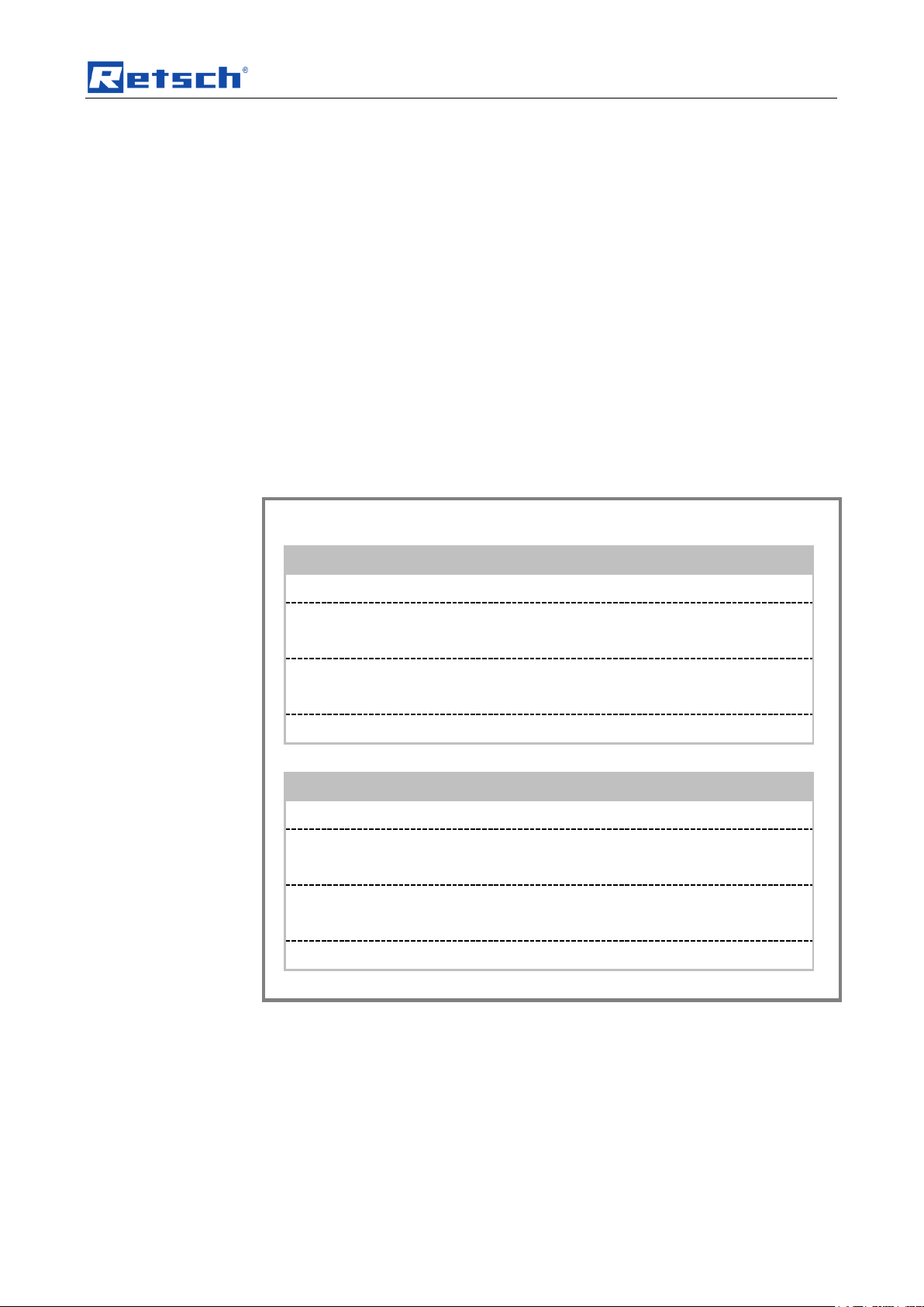
1.1 Explanations of the safety warnings
In this Operating Manual we give you the following safety warnings
Serious injury may result from failing to heed these safety warnings. We give you
the following warnings and corresponding content.
We also use the following signal word box in the text or in the instructions on action
to be taken:
Moderate or mild injury may result from failing to heed these safety warnings.
We give you the following warnings and corresponding content.
We also use the following signal word box in the text or in the instructions on action
to be taken:
In the event of possible property damage we inform you with the word
“Instructions” and the corresponding content.
We also use the following signal word in the text or in the instructions on action to
be taken:
NOTICE
8
Page 9
Notes on the Operating Manual
CAUTION
Read the Operating Manual
Non-observance of these operating instructions
– The non-observance of these operating instructions can
result in personal injuries.
• Read the operating manual before using the device.
• We use the adjacent symbol to draw attention to the
necessity of knowing the contents of this operating
manual.
CAUTION
Changes to the machine
– Changes to the machine may lead to personal injury.
• Do not make any change to the machine and use spare parts and
accessories that have been approved by Retsch exclusively.
NOTICE
Changes to the machine
– The conformity declared by Retsch with the European Directives will lose
its validity.
– You lose all warranty claims.
• Do not make any change to the machine and use spare parts and
accessories that have been approved by Retsch exclusively.
1.2 General safety instructions
Target group : All persons concerned with the machine in any form
This machine is a modern, high performance product from Retsch GmbH and
complies with the state of the art. Operational safety is given if the machine is
handled for the intended purpose and attention is given to this technical
documentation.
You, as the owner/managing operator of the machine, must ensure that the people
entrusted with working on the machine:
• have noted and understood all the regulations regarding safety,
• are familiar before starting work with all the operating instructions and
specifications for the target group relevant for them,
• have easy access always to the technical documentation for this machine,
• and that new personnel before starting work on the machine are familiarised
with the safe handling of the machine and its use for its intended purpose,
either by verbal instructions from a competent person and/or by means of
this technical documentation.
Improper operation can result in personal injuries and material damage. You are
responsible for your own safety and that of your employees.
Make sure that no unauthorised person has access to the machine.
9
Page 10
Notes on the Operating Manual
The Retsch representative in your country
Your supplier
Retsch GmbH directly
Reperaturen
1.3 Repairs
This operating manual does not contain any repair instructions. For your own
safety, repairs may only be carried out by Retsch GmbH or an authorized
representative or by Retsch service engineers.
In that case please inform:
Your Service Address:
10
Page 11
Confirmation
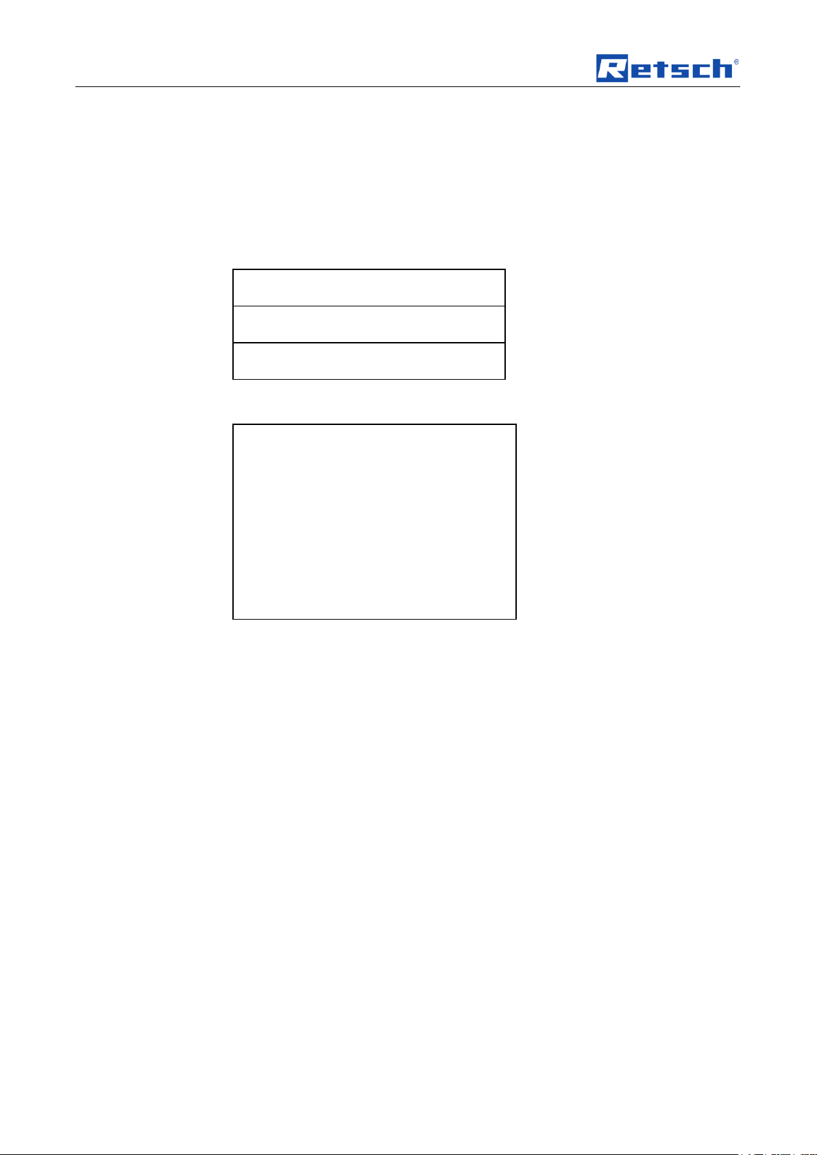
I have read and taken note of the contents of all chapters in this operating
manual as well as all safety instructions and warnings.
User
Surname, first name (block letters)
Position in the company
Signature
Service technician or operator
Surname, first name (block letters)
Position in the company
Place, date and signature
Bestätigung
2 Confirmation
This operating manual contains essential instructions for operating and maintaining
the device which must be strictly observed. It is essential that they be read by the
operator and by the qualified staff responsible for the device before the device is
commissioned. This operating manual must be available and accessible at the
place of use at all times.
The user of the device herewith confirms to the managing operator (owner) that
(s)he has received sufficient instructions about the operation and maintenance of
the system. The user has received the operating manual, has read and taken note
of its contents and consequently has all the information required for safe operation
and is sufficiently familiar with the device.
As the owner/managing operator you should for your own protection have your
employees confirm that they have received the instructions about the operation of
the machine.
11
Page 12
Technical data
CAUTION
Possibility of acoustic signals not being heard
Loud grinding noises
- Acoustic alarms and voice communication might not be heard.
• Consider the volume of the grinding noise in relation to other
acoustic signals in the work environment. You may wish to use
additional visual signals.
CAUTION
V0077
Damage to hearing
A loud sound level may be generated depending on the type of
material, the number of balls used, the grinding frequency set and the
duration of grinding.
– Excessive noise in terms of level and duration can cause
impairments or permanent damage to hearing.
• Ensure suitable noise protection measures are taken or
wear ear protection.
Container:
2 125ml steel grinding jars
Grinding body:
50 10mm steel balls each
Feed material:
Quartz sand, approx. 0.5mm
3 Technical data
3.1 Protective equipment
– This device is equipped with an automatic lid lock. The lock prevents the
device being started when in an unsafe state.
– The device can only be started when the lid is closed.
– It is only possible to open the lid when the device has come to a halt.
– Monitoring of the grinding jar attachment (clamping lever) before starting and
3.2 Degree of protection
3.3 Emissions
during grinding
IP30
Sound parameters:
The sound parameters are also influenced by the properties of the sample
material.
Example 1:
Workplace-related
equivalent continuous sound level Lep (LIm) = 83dB(A)
Operating conditions:
12
Page 13
Feed quantity:
60ml
Speed:
2,000 rpm
Container:
2 125ml zirconium grinding jars
Grinding body:
275g ZrO2 2mm balls each
Feed material:
Quartz sand, approx. 0.5mm + 35ml H2O
Feed quantity:
40g
Speed:
1,500 rpm
CAUTION
V0047
Device falling down
Incorrect erection or insufficient working space
– Due to its weight, the device can inflict personal injury if it falls down.
• Only operate the device on a sufficiently large, strong and stable
workplace.
• Ensure that all feet of the device are positioned securely.
3.4 Rated power
Technical data
Example 2:
Workplace-related
equivalent continuous sound level Lep (LIm) = 76dB(A)
Operating conditions:
~ 2600W (VA)
3.5 Dimensions and weight
Height : 525mm
Width: 625mm
Depth: 645mm
Weight: approx. 120kg without grinding jar
3.6 Required floor space
Height with open hood : approx. 945mm
Width of the base : 625mm
Depth of the base : 655mm
Location
– The device must be placed on a vibration-free and stable surface.
3.7 Receptacle volume
The batch/feed volume depends on the sample material and on the device
configuration or setting:
Batch/feed volume: max. 2 x 45ml
13
Page 14

Technical data
3.8 Feed size
The feed size depends on the sample material and on the device configuration or
setting.
Feed size: < 5mm
3.9 Cooling
3.9.1 Internal
There is a cooling agent tank at the back which must be filled with water before
putting into operation.
NOTICE Only use clean, lime-free water as cooling agent.
Fill volume: 600ml
3.9.2 External
Cooling agent: clean, lime-free water
You can connect additional cooling at the back of the device.
The maximum pressure must not exceed 6bar.
The minimum temperature of the cooling agent must not be less than 5°C.
Only clean, lime-free water is permitted as cooling agent.
14
Page 15

Transport, scope of delivery, installation
NOTICE
Storage of packaging
– In the event of a complaint or return, your warranty claims may be
endangered if the packaging is inadequate or the machine has not been
secured correctly.
• Please keep the packaging for the duration of the warranty period.
NOTICE
Transport
– Mechanical or electronic components may be damaged.
• The machine may not be knocked, shaken or thrown during
transport.
HINWEIS
Reklamationen
– Bei Transportschäden müssen Sie den Transporteur und die Retsch
GmbH unverzüglich benachrichtigen. Spätere Reklamationen können
unter Umständen nicht mehr berücksichtigt werden.
• Benachrichtigen Sie Ihren Transporteur und die Retsch GmbH
innerhalb von 24h.
NOTICE
Temperature fluctuations
The machine may be subject to strong temperature fluctuations during transport
(e.g. aircraft transport)
– The resultant condensed water may damage electronic components.
• Protect the machine from condensed water.
4 Transport, scope of delivery, installation
4.1 Packaging
4.2 Transport
The packaging has been adapted to the mode of transport. It complies with the
generally applicable packaging guidelines.
4.3 Temperature fluctuations and condensed water
4.4 Conditions for the place of installation
Ambient temperature: 5°C to 40°C
15
Page 16
Transport, scope of delivery, installation
NOTICE
Ambient temperature
– Electronic and mechanical components may be damaged and the
performance data alter to an unknown extent.
• Do not exceed or fall below the permitted temperature range of the
machine (5°C to 40°C / ambient temperature).
WARNING
1 2 3
4 5 6 7 8
9
11111
4.5 Installation of the machine
Installation height: maximum 2000 m above sea level
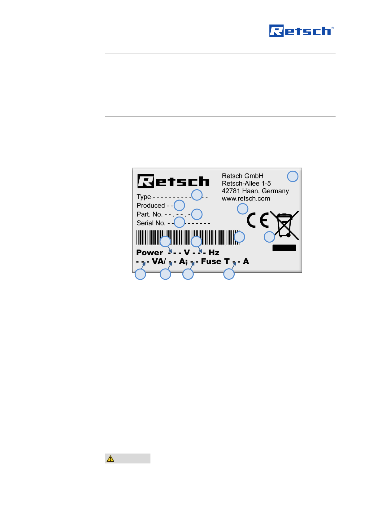
4.6 Type plate description
Fig. 1: Type plate lettering
1 Device designation
2 Year of production
3 Part number
4 Serial number
5 Manufacturer’s address
6 CE marking
7 Disposal label
8 Bar code
9 Power version
10 Mains frequency
11 Capacity
12 Amperage
13 Number of fuses
14 Fuse type and fuse strength
In the case of questions please provide the device designation (1) or the part
number (3) and the serial number (4) of the device.
4.7 Electrical connection
16
Page 17
Transport, scope of delivery, installation
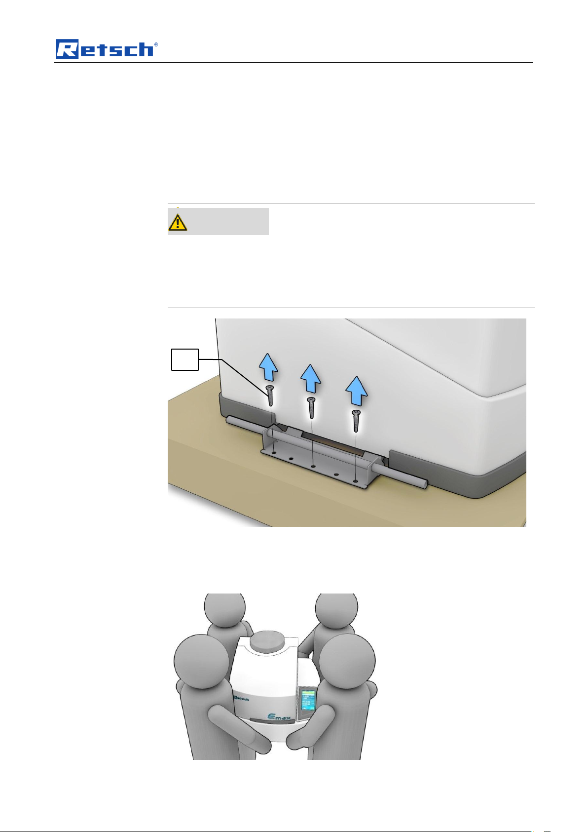
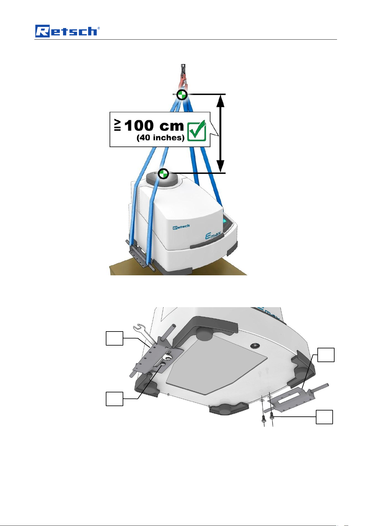
WARNING
Serious personal injury
Falling loads
– The appliance is very heavy and can therefore cause serious personal
injuries if it falls down.
• Lifting above head height is not permissible!
TP
When connecting the power cable to the mains supply, use an external fusethat
complies with the regulations applicable to the place of installation .
• Please check the type plate for details on the necessary voltage and
frequency for the device.
• Make sure the levels agree with the existing mains power supply.
• Use the supplied connection cable to connect the device to the mains power
supply.
4.8 Removing the transport safeguard
Fig. 1: Unscrewing the transport lock
• Unscrew the screws on either side of the device (TP).
NOTICE
The transport lock can also be used as carrying aid.
17
Page 18
Transport, scope of delivery, installation
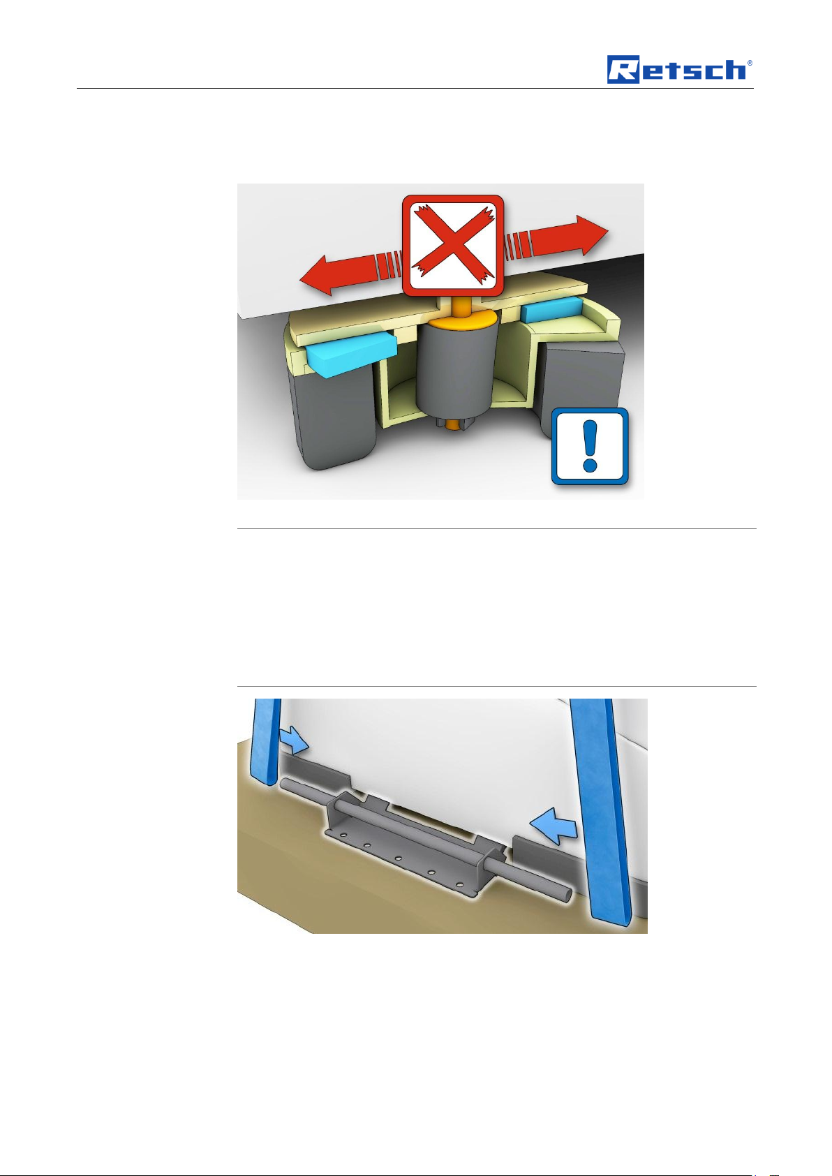
NOTICE
Damage to the feet
Pushing or pulling the device
– The feet oscillate (free-force compensation sockets) and will be damaged if
you pull or push the device across a surface.
• Do not pull or push the device.
• Lift the device to move it.
Fig. 2: Transporting the device
Weight: approx. 120kg without grinding jar
• The device should always be lifted by four people.
Fig. 3: Oscillating feet– do not push the device
Fig. 4: Attaching lifting gear
You can also use the transport aid for lifting the device with a crane.
• Attach the lifting straps to the two transport aids as shown in the diagram.
NOTICE
The housing can be damaged if the lifting straps are too short.
• Use 4 sufficiently long lifting straps.
• Observe the minimum distance between the device and the lifting gear.
18
Page 19
Transport, scope of delivery, installation
TS
TH
TH
TS
Minimum distance: 100cm
Fig. 5: Minimum distance between housing and lifting gear
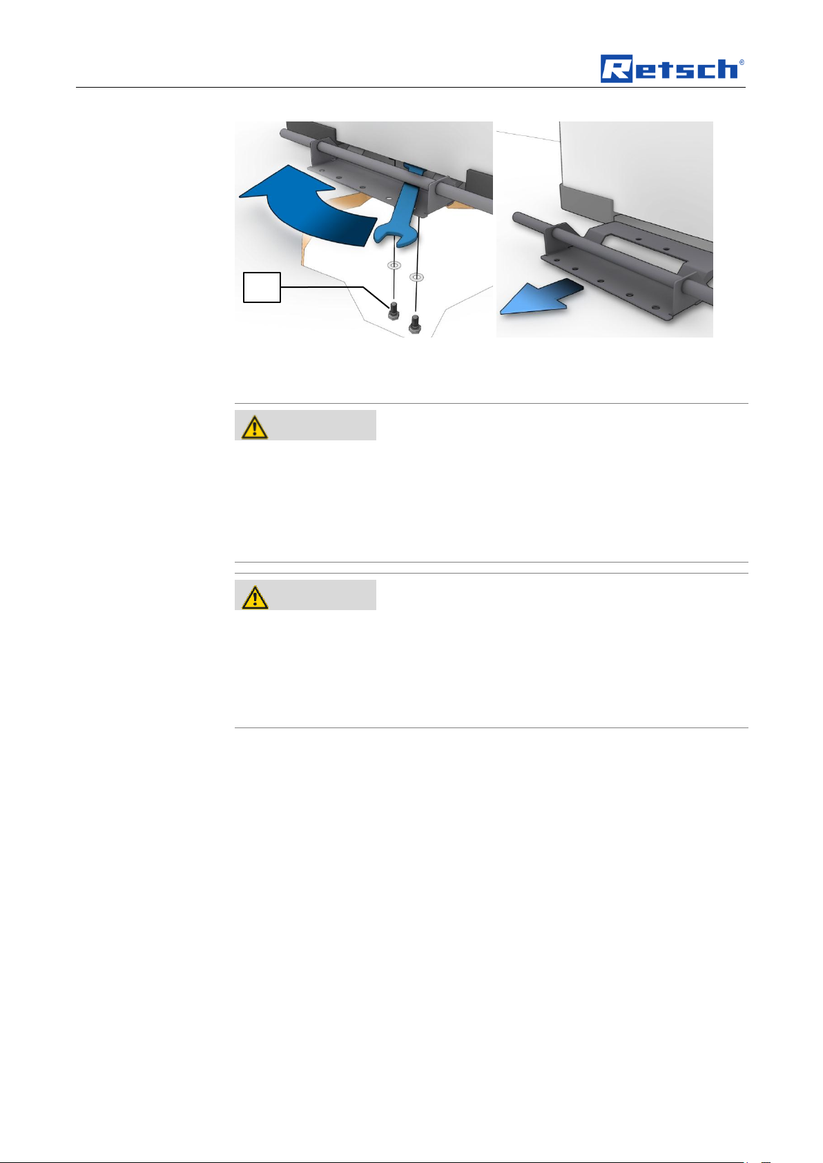
4.9 Removing Transport Safeguards
Fig. 6: Transport aid
The transport aid (TH) is fixed to the underneath of the device.
• Use a 13mm wrench to attach and remove the four screws (TS).
19
Page 20
Transport, scope of delivery, installation
WARNING
Risk of a fatal electric shock
- An electric shock can cause injuries in the form of burns and cardiac
arrhythmia, respiratory arrest or cardiac arrest.
• Do not clean the blender under running water. Use only a cloth dampened
with water.
• Disconnect the power supply plug before cleaning the blender.
WARNING
W0008
Risk of death through power surge
Mains plug not completely plugged in
– Water can enter the IEC socket if the IEC is not completely plugged in. An
electric shock can lead to burns and arrhythmia or to respiratory arrest as
well as cardiac arrest.
• Only operate the device with the IEC fully plugged in.
TS
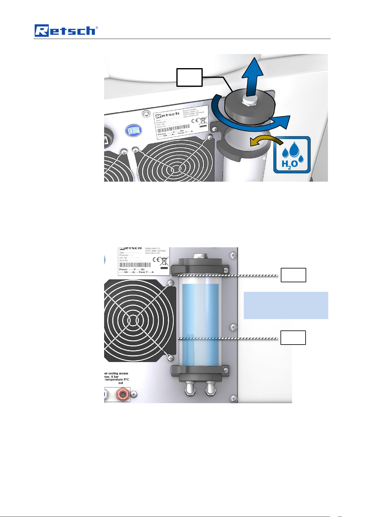
4.10 Cooling
4.10.1 Cooling agent
Fig. 7: Removing the transport aid
There is a cooling agent tank at the back which must be filled with water before
putting into operation. Only clean, lime-free water is permitted as cooling agent.
• Unscrew the lid (TD) to fill the water.
• Start the device up for 2 minutes at a speed of 300 revolutions per minute
(with two grinding jars).
– This activates the internal pump and the cooling agent is distributed in the
cooling system.
• Then close the tank again.
20
Page 21
Transport, scope of delivery, installation
TD
Max
Min
Maximum volume of
cooling agent: 600ml
Fig. 8: Cooling agent tank
Check the supply of cooling agent regularly.
• Only use clean, lime-free tap water when topping up
• Pay attention to dirt in the cooling water. If it is too dirty, the cooling water
must be replaced.
• Maximum volume of cooling agent 600ml.
• Check the cooling system regularly for leaks.
Fig. 9: Maximum and minimum fill level
21
Page 22

Transport, scope of delivery, installation
NOTICE
Error message E46
Flowmeter
– The following error sources can lead to an E46 error message:
1. No cooling agent in the cooling system
2. Flowmeter sensor faulty
3. Pump faulty
4. Blockage in the cooling system
• Check whether sufficient cooling water is in the cooling agent tank
(T).
Cooling agent
Clean, lime-free water
Minimum pump pressure
0.6bar
Maximum pump pressure
6bar
Minimum cooling output at 20°C
1kW
Maximum flow rate
10L/min
Working temperature
0° - 40°C
R
P
4.10.1.1 Connection to an external cooler
If the internal cooling is not sufficient for your application, you have the option of
connecting external cooling using the connections (R/P).
The internal cooling is then supported via the heat exchanger by optional external
cooling.
Fig. 10: Connections for external cooling
The maximum pressure in feed and drain pipes must not exceed 6 bar.
The minimum temperature of the cooling agent may not be less than 5°C.
Only clean, lime-free water is permitted as cooling agent.
The type of connection for the hose connection is 10mm x 8mm.
Alternatively own screw connections with a G ¼” thread may be used.
Cooler specifications:
22
Page 23

Transport, scope of delivery, installation
KF
KF
KF
KF
4.10.2 Grinding jar cooling surfaces
Fig. 11: Grinding jar support cooling surfaces
Fig. 12: Grinding jar cooling surfaces
The grinding jar is cooled by the cooling surfaces (KF) in the grinding jar support
(G). For good cooling performance, the surfaces on the grinding jar and support
must be absolutely clean and level.
• Remove any dirt and adhesion from the grinding jar and support.
• Take care that the surfaces are level and undamaged.
23
Page 24

Operating the machine
CAUTION
Risk of explosion or fire
– On account of its design, the device is not suitable for use in hazardous
(potentially explosive) atmospheres.
• Do not operate the device in a hazardous atmosphere.
CAUTION
Danger of personal injury
Dangerous nature of the sample
– Depending on the dangerous nature of your sample, take the
necessary measures to rule out any danger to persons.
• Observe the safety guidelines and datasheets of your
sample material.
CAUTION
1.V0004
Risk of explosion or fire
Changing sample properties
– Consider that the properties and therefore also the hazardousness of your
sample can change during the grinding process.
• Do not use any substances in this device which carry the risk of
explosion or fire.
NOTICE
Area of use of the machine
– This machine is a laboratory machine designed for 8-hour single-shift
operation.
• This machine may not be used as a production machine nor is it
intended for continuous operation.
5 Operating the machine
5.1 Use of the machine for the intended purpose
This Retsch ball mill is a laboratory device. It grinds and mixes soft, medium-hard
through to extremely hard, brittle and fibrous materials.
Dry and wet grinding may be conducted.
Minerals, ores, alloys, chemicals, glass, ceramics, plant parts, soil, sewage sludge
and many other substances can be ground easily, quickly and without loss. The
ball mills are successfully deployed in almost all areas of industry and research,
especially where there are high demands regarding cleanliness, speed, fineness
and reproducibility.
Only grinding jars from Retsch GmbH may be used.
Grinding with solvents is permitted. In this case the additional comments in the
“Wet grinding with highly flammable materials” chapter should be taken into
consideration, however.
24
Page 25

Operating the machine
25
Page 26

Operating the machine
26
Page 27

Operating the machine
A
H
E
C
D B F
G
5.2 Views of the Instrument
Fig. 13: Front view of the device
27
Page 28
Operating the machine
Element
Description
Function
A
Locking device
Keeps the device closed
B
Operating touchscreen
Operation of the device, starting, stopping etc.
C
Twist grip grinding jar support
Clamps the grinding jar
D
Twist grip locking pin
Secures the twist grip of the grinding jar support
E
Grinding jar
Grinding container
F
Lock retaining bracket
Retaining dowel for hood
G
Grinding jar support clamping bracket
Clamps the grinding jar
H
Hood
Closes the device
28
Page 29

Operating the machine
Element
Description
Function
I
Power switch
Disconnect the device from the mains, automatic fuse
J
RS232 interface (Ethernet)
Data connection (inactive)
K
USB interface
Data connection
L
Warning sign to disconnect from the
mains
Warning of electric shock
M
Mains connection
Connection for power cable
N
Type plate
Voltage type, serial number, device model
O
Housing fans
Fans for lost heat
P
Cooling water outlet for external
cooling (optional)
Hot water outlet
R
Cooling water inlet for external
cooling (optional)
Cooling water inlet
S
Operating instructions sticker
Reminder to read the operating instructions
T
Cooling agent tank for internal cooling
circuit
Cooling water expansion tank / filling
J I K O P R M L S N T
Fig. 14: Back of the device
29
Page 30

Operating the machine
B3.1
5.3 Opening and closing of the grinding chamber
5.3.1 Opening
When automatic opening is active, the grinding chamber lid is automatically lifted
once grinding has ended (see Service menu chapter).
When deactivated, the grinding chamber lid must be opened manually at the end of
grinding using the OPEN button (B3.1).
• To open the device, tap on the (B3.1) button.
– The display on the button (B3.1) changes to .
5.3.2 Closing
Fig. 15: Opening the hood
• Press the hood down until you notice that the automatic locking has closed
the lid.
– The display on the button (B3.1) changes to .
30
Page 31

Operating the machine
NOTICE
Hood is not closed
Automatic locking has not engaged
– If the hood has not closed sufficiently when it is closed, the automatic lock
cannot engage.
• Open the automatic locking:
To open the device, tap on the OPEN button (B3.1).
• Use a little force to press the hood downwards until you notice that
the automatic locking has closed the lid.
CAUTION
Emergency Unlocking
Drive continuing to run
– There is a substantial risk of injury if the drive and associated device parts
run on a long time without being braked!
• Activate the emergency unlocking only when the machine has come
to a complete stop and is disconnected from the power supply.
Eh
Fig. 16: Closing the hood
5.4 Emergency unlocking
Electrical unlocking is not possible in the case of a power outage.
– Open the hood with the release mechanism (Eh) .
Fig. 17: Position of the emergency release
31
Page 32

Operating the machine
CAUTION
Scalding/burns
Hot grinding jar
– Depending on the grinding process, the material being ground and
accordingly the grinding jar can become very hot.
• Wear appropriate protection always when touching the grinding jar if
it is hot.
Eh D C
DN
Fig. 18: Activating the emergency release
5.5 Opening and closing the grinding jar support
5.5.1 Opening
Fig. 19: Releasing the grinding jar support
The twist grip (C) of the grinding jar support (G) is secured by locking pin (D) to
prevent inadvertent opening.
32
Page 33

Operating the machine
G
DN
C
D
V
• Pull out the locking pin (D) to release from the groove (DN).
• Twist the locking pin 90 degrees to release it permanently.
• Turn the twist grip (C) to open the grinding jar support.
• Only remove the grinding jar with closed lid.
• Only open the grinding jar in a safe position (e.g. extraction device).
• Only open the grinding jar once it has cooled down.
5.5.2 Closing
Fig. 20: Removing the grinding jar
With this grinding device, a very large amount of energy enters the sample
material.
• Therefore make sure that the grinding jar support has been closed properly.
• Before grinding check the lock on the grinding jar support (V).
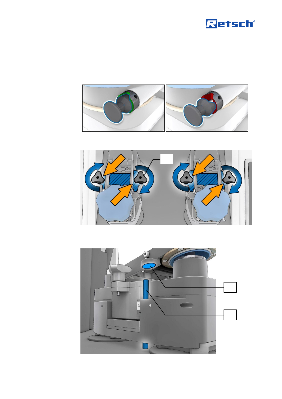
Fig. 21: Locking the grinding jar support
The twist grip (C) of the grinding jar support (G) is secured by locking pin (D) to
prevent inadvertent opening.
• Twist the locking pin (D) until it engages in the groove (DN).
33
Page 34
Operating the machine
MG
MV
SP
• Turn the twist grip (C) anticlockwise and tighten the twist grip (C) only hand-
tight when closing.
No greater force than “hand-tight” is required because the twist grip is secured by
the locking pin.
NOTICE
As a check that the lock has been activated, when the lock (D) has been closed
correctly a rattling sound can be heard when turning the twist grip (C).
Fig. 22: Securing and opening the locking pin
Fig. 23: Pulling the grinding jar lock tight
• After tightening the grinding jar support (G) with the twist grip (C), check the
tension on the 4 clamping screws (SP).
Fig. 24: Monitoring the grinding jar support
34
Page 35
Operating the machine
Grinding jar material
Temperature
Stainless steel
Up to 200°C
Tungsten carbide
Up to 150°C
Zirconium oxide
Up to 120°C
DM
SP
To avoid operating errors, the correct position of the grinding jar support is queried
using a magnet (MG) via extension (MV) and the corresponding sensor before
each start of the machine and during grinding.
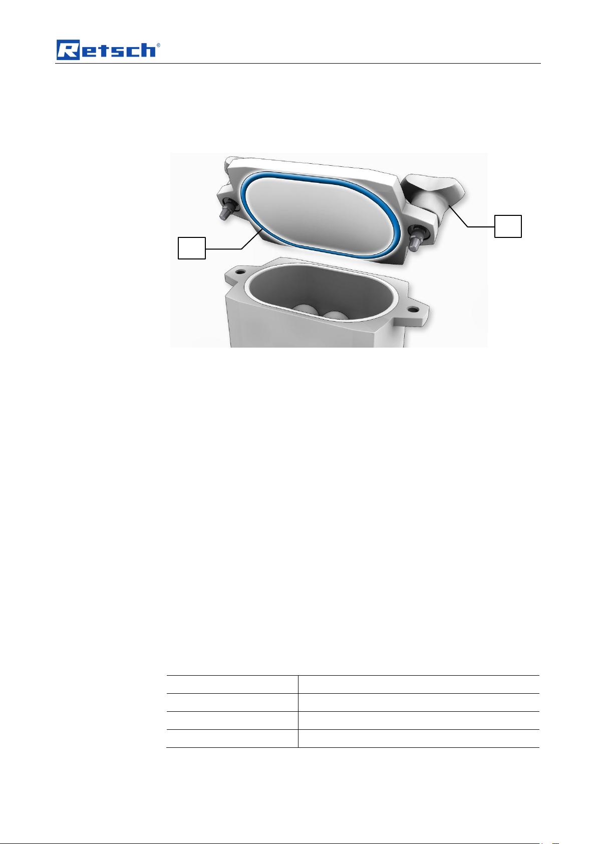
5.6 Closing the grinding jar
Fig. 25: Closing the grinding jar
With this grinding device, a very large amount of energy enters the sample
material.
• Therefore ensure careful closing of the grinding jar.
• When closing the grinding jar, ensure the seal (DM) is firmly in place.
• Tighten the clamping screws (SP) of the locking device so they are hand-
tight.
• Check the tension on the 4 clamping screws (SP) after closing the grinding
jar support (G) with the twist grip (C).
• Please note that the grinding jar can heat up to over 100°C depending on
the grinding jar size, the ball filling, the speed and the grinding duration.
5.6.1 Grinding jar and lid identification
All grinding jars must be identified by the labelling area which shows the grinding
jar material.
Grinding jars, also those with glued ceramic inserts, can be cleaned with alcohol,
petrol or normal household washing-up liquid.
NOTICE
– Ceramic inserts can crack as a result of sudden temperature differences.
• Do not expose grinding jars with ceramic inserts to sudden temperature
differences.
5.6.2 Drying the grinding jars
The grinding jars may be dried in the drying cabinet at the following specified
temperature at any time after cleaning.
35
Page 36
Operating the machine
Grinding jar
Ball size
125ml
Up to 15mm
50ml
Up to 12mm
Grinding jar material
Revolutions per minute
Steel
Up to 1500
Tungsten carbide (WC)
Up to 1200
Zirconium oxide
Up to 1200
NOTICE
H0067
Strong vibrations and noises
Uneven loading
– In the event of uneven loading the device can generate especially strong
vibrations and noises.
• Always use 2 grinding jars.
• Switch the device off immediately in the event of strong vibrations
and noises and check the number and gross weight of the jars.
5.7 Ball sizes and speeds
With this grinding device, a very large amount of energy enters the sample
material. This high amount of energy also acts on the grinding jar and the grinding
balls.
– The following recommendations for the ball sizes used therefore apply
depending on the grinding jar size.
– Likewise note the recommended speeds depending on the grinding jar
material.
5.7.1 Recommended ball sizes
5.7.2 Recommended speeds
The following speed restrictions apply to balls larger than 10mm:
5.8 Inserting the grinding jar
36
Page 37

Operating the machine
G
Fig. 26: Both grinding stations must be loaded
Fig. 27: Inserting the grinding jar
5.9 Wet grinding with highly flammable materials
Wet grinding using highly flammable materials is permissible in this device when
complying with specific precautionary measures.
When using highly flammable materials as grinding aid, such as hexane,
isopropanol, ethanol, petrol or similar, it is to be assumed that the inside of the
grinding jars should be classed as Zone 0 – constantly present explosive mix.
Therefore it is necessary to prevent potentially explosive vapours during the
grinding process - and in particular also from the heating which takes place - from
escaping from the clamped grinding jars and from entering areas in which the
requisite ignition energy is present.
We therefore urgently recommend that the operating company (employer) using
the device assesses the dangers that exist before using corresponding solvents,
taking local conditions into account, as part of a coherent explosion protection
37
Page 38

Operating the machine
concept. Where necessary, supplementary organisational measures should be
recorded in writing in an explosion protection document.
This procedure is regulated in the EU under Articles 118 and 118a of Directive
89/391/EEC.
Please observe comparable provisions in other countries outside the EU.
The following requirements should be assumed here with respect to the device.
• It is necessary to consider the durability of the O-rings (FPM Viton) when
selecting the solvent and the durability of the adhesive used when using
ceramic material inserts.
• Tighten the clamping screws of the locking device so they are hand-tight.
• Please note that the grinding jars can heat up considerably depending on the
grinding jar size, the ball filling, the speed and the grinding duration.
• Check that the lock is firmly in place before removing the grinding jars.
38
Page 39
Control panel software – controlling the device
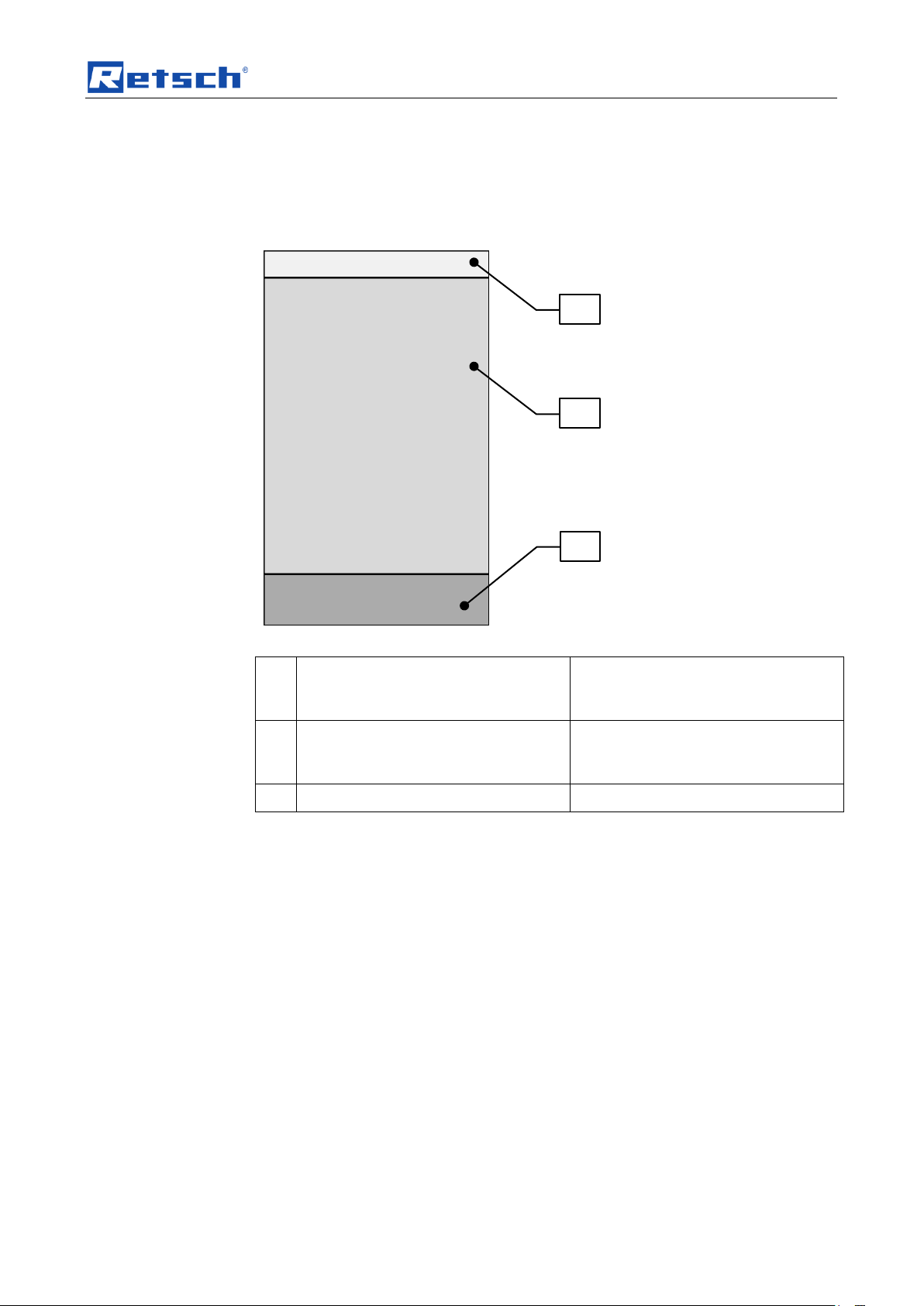
B1
Navigation
Switching between Manual, Program
and Sequences
Time, Date
B2
Setting and display of parameters
Setting the grinding parameters and
displaying parameters during
grinding
B3
Device controller
Start, Stop, Pause, Lid open
B1
B2
B3
6 Control panel software – controlling the device
6.1 Operating elements and displays
Fig. 28: Screen areas
39
Page 40

Control panel software – controlling the device
22.04.2014
14:23
PROGRAM
65°C
Temperature
Interval
Reverse direction
01:00:00
Process time
1800
Speed (U/min)
00:15:00
Interval time
00:05:00
Pause time
OPEN
START
10 | Aluminium oxide
B1.1
B2.1
B2.3
B2.5
B2.7
B2.8
B2.9
B3.1
B1.2
B2.2
B2.6
B2.11
B3.2
B2.4
B2.10
70°C
50°C
40
Page 41

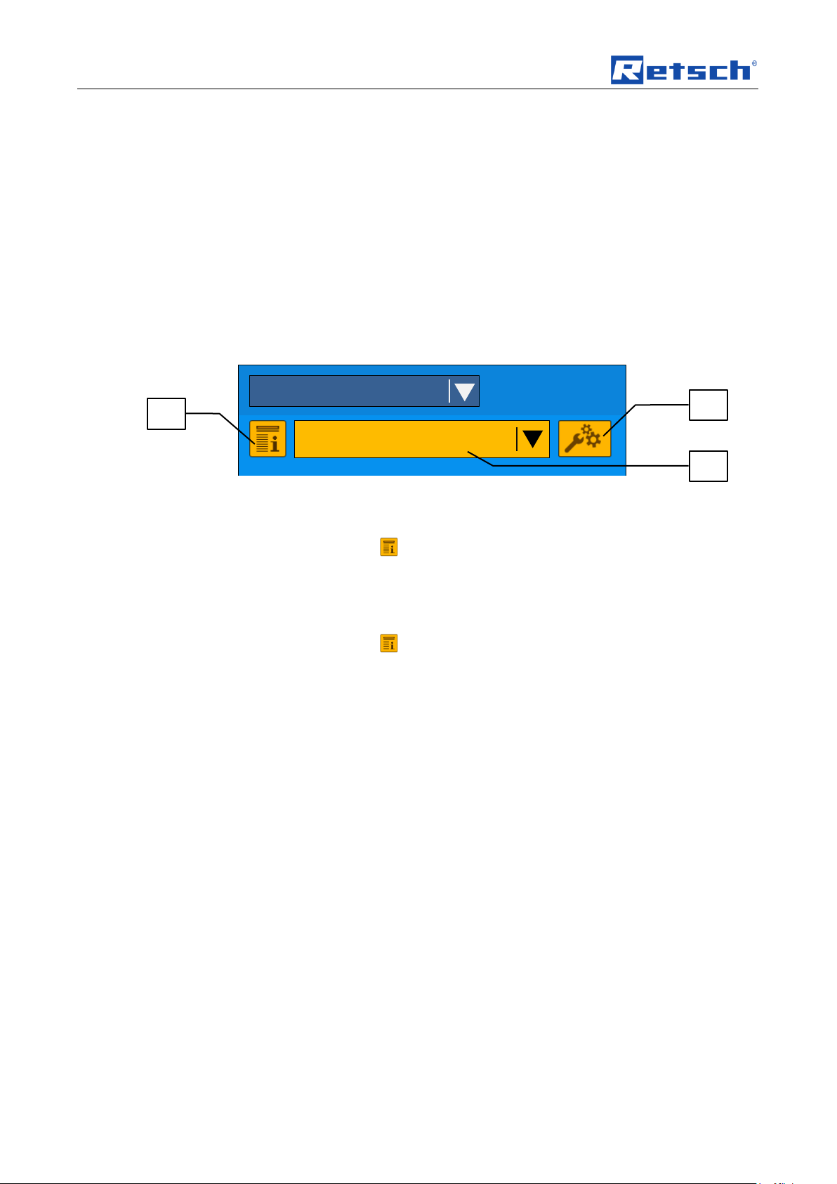
Control panel software – controlling the device
Element
Description
Function
B1.1
Navigation
Switching between Manual, Program and
Sequences
B1.2
Display of time
Display of the date and time / access to the device
menu
B2.1
Program information
Retrieval of user data for the current program
B2.2
Edit program
Opens the settings menu for the current program
B2.3
Cooling
Display of the cooling status flow (active / inactive);
upper and lower temperature limit
B2.4
Program designation
Display of the program number and of the saved
program name; selection of the desired program
B2.5
Process time
Display of the grinding duration
B2.6
Display of temperature and
temperature limits
Display of the water temperature in the cooling
system
B2.7
Speed
Display of the speed, reverse grinding
B2.8
Interval
Display of whether interval grinding is active or
inactive
B2.9
Interval time
Display of the interval time
B2.10
Pause time
Display of the pause time
B2.11
Reverse direction
Display of whether the direction reversal is active or
inactive
B3.1
OPEN
Opens the hood
B3.2
START
Starts grinding
6.2 Functional principle (resistive) of the touchscreen
With this resistive touchscreen two electrically conductive layers are connected in
places as a result of pressure in order to determine the position of the pressure
point.
For this reason the operation takes place exclusively using single touch entries.
The advantage of this is that you can also operate the touchscreen when wearing
gloves or using a stylus.
6.3 Operating modes and navigation
The device can be operated entirely using the touchscreen.
The operating software can be divided into three operating modes:
– Manual
– Program
– Sequences
6.3.1 Navigation between operating modes
• Tap on the navigation field (B1.1).
– The navigation menu opens.
– The current mode is marked (by a triangle and coloured lettering)
41
Page 42

Control panel software – controlling the device
22.04.2014
14:23
65 C°
Temperatur
01:00:00
Prozesszeit
10 | Aluminiumoxid
PROGRAM
PROGRAM
MANUAL
SEQUENCE
B1.1
• Tap on the desired mode.
6.4 Grinding parameters
You can change the following grinding parameters.
6.4.1 Adjustable parameters
– Process time 00:00:00 to 99:59:59 (hh:mm:ss)
– Interval time 00:00:00 to 99:59:59 (hh:mm:ss) – only active with interval
– Pause time 00:00:00 to 99:59:59 (hh:mm:ss) – only active with interval
– Speed 300 to 2000 in increments of 100 (revs per minute)
In manual operating mode you can also change some parameters during grinding.
In program mode you can only change parameters when you have activated
editing using the icon (B2.2).
• Tap on the parameter that you wish to edit.
– The window to make entries appears.
• Tap on CANCEL to cancel editing without saving entries.
– The entries are not saved, and the menu displays the previous screen.
• Tap on SAVE to save entries.
The entries are saved, and the menu displays the previous screen.
42
Page 43

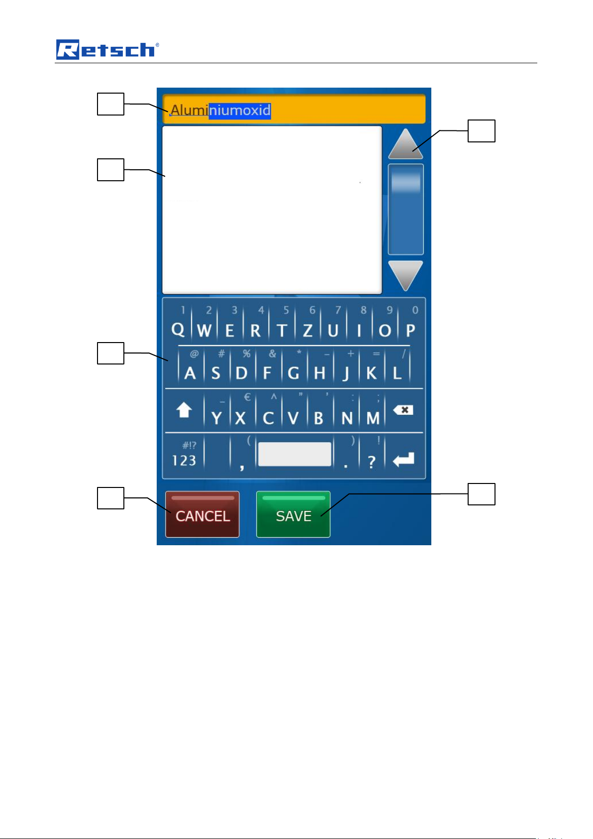
Control panel software – controlling the device
Fig. 29: Making entries
6.4.2 Parameters that can be activated or deactivated
– Interval
– Reverse direction
• Tap on the interval line (B2.8)
– Depending on the previous status, interval grinding is then active or inactive.
The parameters for interval time, pause time and reverse direction are
switched to active or inactive according to the activation of interval grinding.
6.5 Manual operation
You can change the following grinding parameters directly in manual operating
mode.
– Process time
– Interval time
– Pause time
– Speed
– Interval
– Reverse direction
The parameters are adjusted as described in the “Grinding parameters” chapter.
43
Page 44
Control panel software – controlling the device
22.04.2014
14:23
PROGRAM
65 C°
Temperatur
Intervall
Richtungsumkehr
01:00:00
Prozesszeit
1800
Drehzahl (U/min)
00:15:00
Intervallzeit
00:05:00
Pausenzeit
OPEN
START
10 | Aluminium oxide
B2.1
B2.2
B2.4
6.6 Programs
You can save up to 10 grinding programs.
You can save the following grinding parameters in a program:
– Process time
– Interval time
– Pause time
– Speed
– Interval
– Reverse direction
Additionally you can allocate every program its own heading and a detailed
description.
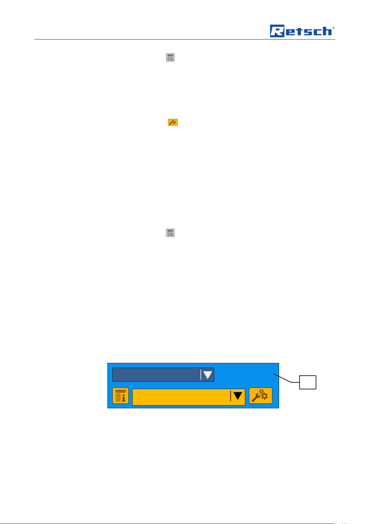
6.6.1 Program description and heading
6.6.1.1 Display of the program description
• Tap on the icon (B2.1).
– The program description window opens.
• Tap on the BACK button to return to the previous screen.
6.6.1.2 Edit the program description and the heading
• Tap on the icon (B2.1).
– The program description window opens.
• Tap on the EDIT button to enter or edit the program description or the
heading.
– The window for editing the program description opens.
44
Page 45
Control panel software – controlling the device
B4.1
B4.6
B4.2
B4.3
B4.5
B4.6
Fig. 30: Window for editing the program description
• To edit the heading, tap the field (B4.1).
– Use the keypad (B4.3) for entries and editing.
• To edit the program description, tap the field (B4.2).
– Use the keypad (B4.3) for entries and editing.
– You can use the arrow keys (B4.6) to scroll up and down longer areas of
text.
6.6.1.3 Saving or cancelling editing of the program description or heading
• Tap on CANCEL to cancel editing without saving the description.
– The entries are not saved, and the menu displays the previous screen
(program description).
• Tap on SAVE to save the description.
– The description is saved, and the menu displays the previous screen
(program description).
45
Page 46

Control panel software – controlling the device
6.6.2 Selecting saved programs
• Tap on the headings field (B2.4).
– The program selection window opens.
– The current program is shown with a grey background.
• Tap on an icon to open the program description of the respective
program.
• Tap on the desired program.
– The program selection window closes and the relevant program is loaded.
6.6.3 Editing and saving the program
In the program mode you can only change parameters if you have activated
editing.
• Tap on the icon (B2.2) to edit the grinding parameters saved in the
program.
The parameters are set as describing in the “Grinding parameters” chapter.
• Tap on CANCEL to cancel editing without saving entries.
– The entries are not saved, and the menu displays the previous screen.
• Tap on SAVE to save the entries.
– The entries are saved, and the menu displays the previous screen.
6.7 Sequences
For special grinding tasks you can collate your previously saved programs into a
sequence in this mode. This enables you to design very complex grinding
processes.
– A sequence is made up of a number of freely selectable programs.
– You can repeat programs.
– You can save up to three sequences.
46
Page 47

Control panel software – controlling the device
22.04.2014
14:23
SEQUENCE
65°C
Temperature
01:00:00
Process time
OPEN
START
1 | Retsch sequence
B5.1
B5.5
B5.8
B5.2
B5.4
70 C°
50 C°
– The grinding parameters of the individual programs cannot be changed in
the sequence mode. To do this, switch to the program mode.
6.7.1 Creating or editing a sequence
1 | Program 5 | P5
2 | Grinding 0001 | P1
3 | Intermediate program | P3
4 | Grinding 0001 | P1
5 | Intermediate program | P3
6 | Intermediate program | P3
7 | Program 5 | P5
6.7.2 Sequence description and heading
You can allocate each of the three sequences its own heading and a detailed
description.
6.7.3 Selecting a saved sequence
• Tap on the icon (B5.1).
All other steps are the same as those explained in the Program description and
heading chapter.
• Tap on the headings field (B5.4).
– The sequence selection window opens.
– The current sequence is shown with a grey background.
47
Page 48
Control panel software – controlling the device
22.04.2014
14:23
PROGRAM
10 | Aluminium oxide
B2.2
• Tap on an icon to open the sequence description of the respective
sequence.
• Tap on the desired sequence.
– The sequence selection is closed and the relevant sequence is loaded.
6.7.4 Editing and saving a sequence
You can only change the program compilation of a sequence if you have activated
editing.
• Tap on the icon (B5.2) to edit the programs saved in the sequence.
The process times of all programs saved in the sequence are added together and
shown in the process time display.
After editing:
• Tap on CANCEL to cancel editing without saving entries.
– The entries are not saved, and the menu displays the previous screen.
• Tap on SAVE to save entries.
– The entries are saved, and the menu displays the previous screen.
6.7.4.1 Adding or changing a program to the sequence
• Tap on the last line in the memory that can be edited and which is shown by
[ – ].
– The list of all saved programs appears.
• Tap on an icon to open the program description of the respective
program.
• Tap on the line for the desired program.
– The program is added to the sequence and the menu displays the previous
screen.
6.7.4.2 Removing a program from the sequence
• Tap on the line in the memory showing the program you wish to remove.
– The list of all saved programs appears.
• Tap on the top line (no program).
– The program is removed from the sequence and the menu displays the
previous screen.
6.8 Service menu
The service menu can be accessed from any operating mode.
• Press and hold the time and date field (B2.2).
– The service menu is displayed full screen.
48
Page 49

Control panel software – controlling the device
22.04.2014
14:23
OPEN
BACK
Language
SETTINGS
Date and time
Signal tone
Automatic opening
Timer setting
IR sensor
Set temperature limits
Operating hours
Software version
User information
Service environment
You can change the following settings in the service menu:
– Language
– Date and time
– Signal tone
– Automatic opening
– Timer setting
– IR sensor calibration
– Set temperature limits
– Operating hours
– Software versions
– User information
– Service environment
49
Page 50
Control panel software – controlling the device
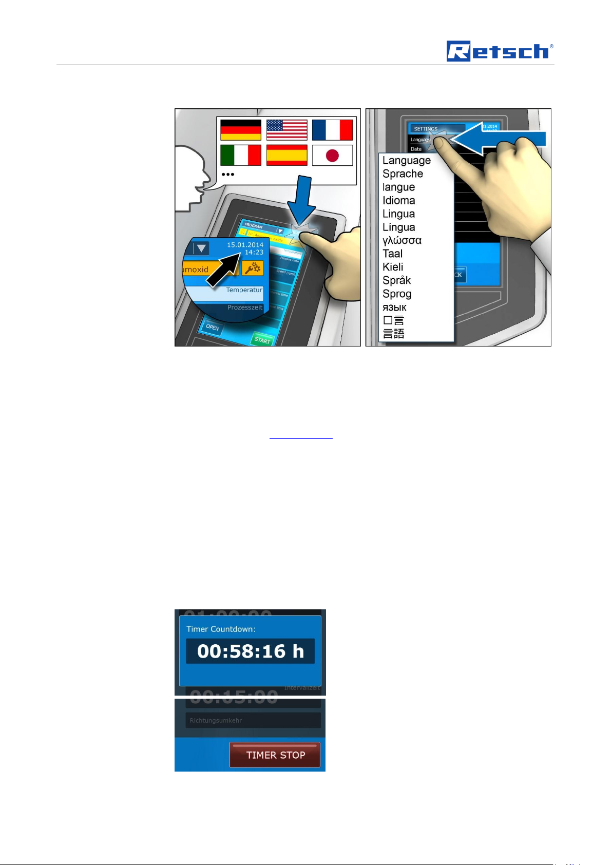
6.8.1 Language
6.8.2 Date and time
6.8.3 Timer – setting
Fig. 31: Accessing the language setting
You can select your language in this menu.
• Tap the desired language on the field.
After selection, the entire menu structure is displayed in the selected language.
NOTICE
The exception is the device control (B3) screen area. The buttons for device
control are displayed in English only.
You can save or change the current date and time under this menu item.
The device can be disconnected from the mains for up to 30 days without losing
the settings.
With the timer function the device can be started with time lag.
The start button is used to confirm the function (the countdown starts running).
• You can interrupt the running down of the start time using the STOP button
and the main switch on the back of the device.
The start time must then be programmed again.
50
Fig. 32: Countdown
Page 51

Control panel software – controlling the device
6.8.4 Setting temperature limits
Fig. 33: Temperature limits
With the temperature limits function you can create grinding pauses in addition to
the actual temperature monitoring.
The grinding is driven at the set speed until it reaches the set max. temperature.
On reaching the maximum temperature, the speed is reduced to 300 rpm until the
minimum temperature is reached. Once the minimum temperature has been
reached, grinding takes place at the set speed again.
NOTICE
After confirming the temperature limits, in addition to the temperature display an
icon and the set temperatures appear on the display (B2.5).
Fig. 34: “Temperature limits active” icon
6.8.5 Automatic opening
With automatic opening the grinding chamber lid is automatically lifted once
grinding has ended.
When deactivated, the grinding chamber lid must be opened manually using the
OPEN button (B3.1).
6.8.6 Signal tone
Error messages in the case of incorrect operation are signalled acoustically by an
alert.
When the function has been turned off, the corresponding pictogram appears
6.8.7 Operating hours
The process times, i.e. the times between START and STOP are counted. The
times cannot be manipulated.
6.8.8 Software versions
In this menu you can update two software areas.
51
Page 52

Control panel software – controlling the device
- Controller (firmware)
- Display
• Tap on the desired update.
NOTICE
A suitable USB data medium with controller and display software must be
connected to the device. The controller and display software must be in the root
directory. The device then automatically recognises the new software.
6.8.9 User information
The following information about the device can be found under user information:
- Accessories
- Spare parts
- User manual
6.8.10 IR sensor calibration
Fig. 35: IR sensor calibration
You can calibrate the IR sensor in this menu.
This is used to measure the temperature of the grinding jar and to adjust it where
necessary.
• Select the field in which you want to adjust the temperature.
6.8.11 Service environment (password protected)
This function can only be accessed by Retsch service technicians.
52
Page 53

Safety functions and fault display
Error code
Description
Measures
E10
Drive overloaded
Press the main switch
E20
Error controller
Press the main switch
E21
Error speed
Press the main switch
E25
Error display
Press the main switch
E26
Error frequency inverter
Press the main switch
E40
Error sensor 1
Confirm message on display
E41
Error speed sensor
Press the main switch
E42
Error temperature sensor 1
Press the main switch
E43
Error temperature sensor 2
Press the main switch
E45
Error sensor 2
Press the main switch
E46
Error sensor 3
Press the main switch
E50
Error safety circuit
Press the main switch
E51
Error safety switch
Press the main switch
E52
Error switch 1
Press the main switch
E53
Error switch 2
Press the main switch
E81
Unbalance
Press the main switch
E87
Unbalance switch
Press the main switch
H10
Allow drive to cool!
Confirm message on display
E100
Temperature limit reached
Confirm message on display
E128
Note temperature limit reached
Confirm message on display
7 Safety functions and fault display
7.1 Fault messages
53
Page 54

Safety functions and fault display
7.2 Returning for service and maintenance
Fig. 2: Returned goods dispatch note
RETSCH devices and accessories can only be accepted for repair, maintenance or
calibration if the returned goods despatch note has been correctly completed in full.
• When returning a device, attach the returned goods dispatch note to the
outside of the packaging.
In order to eliminate any health risk to our employees, we reserve the right to
refuse acceptance and to return the respective delivery at the expense of the
sender.
54
Page 55

Cleaning, wear and service
WARNING
Risk of a fatal electric shock
- An electric shock can cause injuries in the form of burns and cardiac
arrhythmia, respiratory arrest or cardiac arrest.
• Do not clean the blender under running water. Use only a cloth dampened
with water.
• Disconnect the power supply plug before cleaning the blender.
CAUTION
Personal injury
Incorrect repairs
– This operating manual does not include instructions for repair.
• For your own safety repairs should be carried out only by Retsch
GmbH or an authorised representative (service technicians).
8 Cleaning, wear and service
8.1 Cleaning
8.2 Wear
Cleaning
Check at regular intervals whether water or grease are escaping in or beneath the
device.
The grinding tools may become worn, depending on the frequency of the grinding
operation and the sample material. The grinding jars and the balls should be
regularly checked for wear and replaced if necessary.
Check the seals regularly for wear and replace them where necessary.
8.3 Wearing parts
8.4 Service
The grinding tools may become worn, depending on the frequency of the grinding
operation and the sample material. The grinding jars and the balls should be
regularly checked for wear and replaced if necessary.
55
Page 56

Cleaning, wear and service
AG T TD
DS
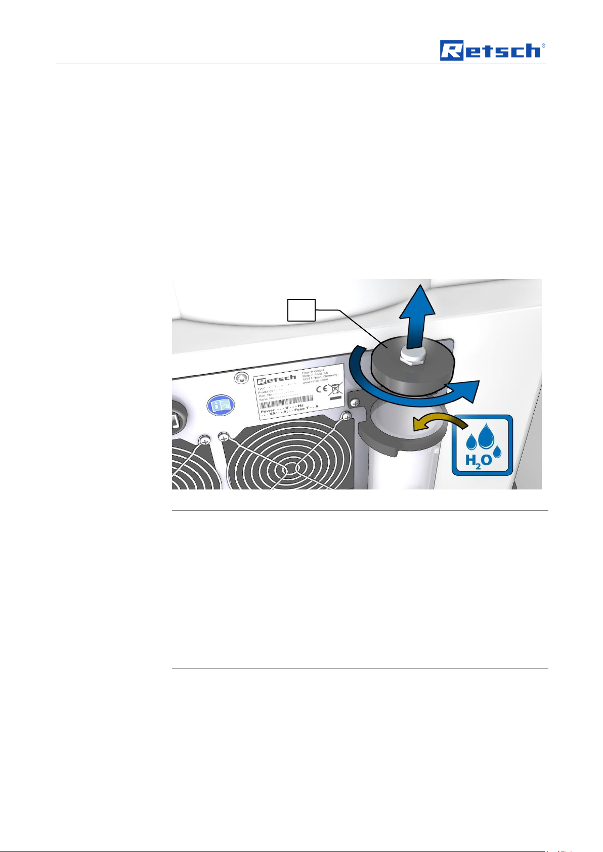
8.4.1 Replacing the cooling water
8.4.1.1 Removing the cooling water
Fig. 36: Replacing the cooling agent
1. Place a collecting vessel (AG) for the old cooling water under the cooling
agent tank (T).
56
Fig. 37: Removing the lid
2. Unscrew the lid (TD).
3. Remove the sealing screw (DS) to drain the water.
4. Start the device up for 1 minute at a speed of 300 revolutions per minute
(with two grinding jars).
– This activates the internal pump (U) and the remaining cooling agent is
pumped out.
Page 57

Cleaning, wear and service
min.
max.
Maximum cooling agent
volume: 600ml
TR
TB
Fig. 38: Removing the pipe
5. After stopping the device you can remove and clean the pipe (TR).
6. Also clean the base (TB).
7. Reinsert the pipe (TR).
– Ensure the seal is firmly in place.
8. Screw in the sealing screw (DS).
8.4.1.2 Rinsing the cooling system
1. Fill with fresh, clean, lime-free tap water (maximum cooling agent volume
600ml).
Fig. 39: Maximum and minimum fill levels
2. Start the device up for 1 minute at a speed of 300 revolutions per minute
(with two grinding jars).
57
Page 58
Cleaning, wear and service
NOTICE
Error message E46
Flowmeter
– The following error sources can lead to an E46 error message:
1. No cooling agent in the cooling system
2. Flowmeter sensor faulty
3. Pump faulty
4. Blockage in the cooling system
• Check whether sufficient cooling water is in the cooling agent tank
(T).
TD
3. Place an empty collecting vessel (AG) to catch the drained cooling water
under the cooling agent tank (T).
4. Remove the sealing screw to drain the water (DS).
5. Screw the sealing screw (DS) back in.
6. Repeat steps 1 to 5 approx. 3 times.
– A residual cloudiness of the water remains after changing the water several
times. This is quite normal.
1. Only fill with fresh, clean, lime-free tap water (maximum cooling agent
600ml).
• Start the device up for 2 minutes at a speed of 300 revolutions per minute
(with two grinding jars
– This activates the internal pump and the cooling agent is distributed in the
cooling system.
• Screw the lid (TD) back onto the cooling agent tank (T).
Fig. 40: Cooling agent tank
• Ensure that the seal is firmly in place.
• Check the cooling system regularly for leaks.
58
Page 59

Cleaning, wear and service
59
Page 60

Disposal
9 Disposal
Please observe the respective statutory requirements with respect to disposal.
Information on disposal of electrical and electronic machines in the European
Community.
Within the European Community the disposal of electrically operated devices is
regulated by national provisions that are based on the EU Directive 2002/96/EC on
Waste Electrical and Electronic Equipment (WEEE).
Accordingly, all machines supplied after 13.08.2005 in the business-to-business
area to which this product is classified, may no longer be disposed of with
municipal or household waste. To document this they have the following label:
Fig. 3: Disposal label
Since the disposal regulations within the EU may differ from country to country we
would request you to consult your supplier.
60
Page 61

10 Index
A
Additional cooling 14
Ambient temperature 15
Amount of energy 36
Amperage 16
B
Back of the device 29
Ball size 36
Bar code 16
Base
Depth 13
Width 13
Batch 13
Blockage 22, 58
C
Capacity 16
CE marking 16
Changes 7
Cleaning 55
Cleaning, wear and service 55
Closing 30
Closing the grinding jar 35
Conditions for the place of installation 15
Confirmation 11
Connection cable 17
Control panel 39
Control panel software – Controlling the device 39
Controlling the device 39
Coolant 14
Cooling 14, 20
Cooling agent 20
Cooling surfaces 23
Cooling water
replacement 56
Copyright 7
D
Degree of protection 12
Depth 13
Description 28, 29, 41
Device designation 16
Dimensions and weight 13
Disposal 60
Disposal label 16
Disposal label 60
Drying the grinding jars 35
E
E46 22, 58
Electrical connection 16
Emergency unlocking 31
Emissions 12
Energy input 36
Error message
E46 22, 58
Error messages 53
Explanations of the safety warnings 8
External 14
External fuse 17
F
Fault messages 53
feed size 14
Feed size 14
Feed volume 13
Fill level 21, 57
Front view 27
Function 28, 29, 41
Fuse strength 16
Fuse type 16
G
General safety instructions 9
Grinding jar cooling surfaces 23
Grinding jar support
closing 32
locking 33
opening 32
Grinding parameters 42
H
Height
with open hood 13
Height 13
Hood
closing 31
opening 30
I
Inserting the grinding jar 36
Installation height 16
Installation of the machine 16
Internal 14
Interval 43
Interval time 42
L
Language 50
Locking pin 33
L
12, 13
pAeq
M
Mains frequency 16
Manual operation 43
Manufacturer’s address 16
Maximum pressure 14
Minimum temperature 14
Moderate or mild injury 8
Monitoring 34
61
Page 62

N
Navigation
manual 41
program 41
sequence 41
Notes on the Operating Manual 7
Number of fuses 16
O
Opening 30
Opening and closing of the grinding chamber 30
Operating elements and displays 39
Operating modes 41
Operating the machine 24
Oscillating feet 18
P
Packaging 15
Parameters
setting 42
Part number 16
Pause time 42
Power version 16
Pressure 14
Process time 42
Program
editing 46
saving 46
selecting 46
Program description 44
display 44
edit 44
Programs 44
property damage 8
Protective equipment 12
Pump faulty 22, 58
R
S
Safety functions and fault display 53
Safety warnings 8
Sensor faulty 22, 58
Sequence
editing 48
saving 48
selecting 48
Sequences 46
Serial number 16
serious injury 8
Service 55
Service Address 10
Service menu 48
Sound parameters 12
Speed 36, 42
Speed restriction 36
T
Target group 9
Technical data 12
Temperature fluctuation and condensed water 15
Touchscreen
functional principle 41
resistive 41
Transport 15
Transport, scope of delivery, installation 15
Type plate 17
type plate description 16
Type plate lettering 16
U
Use of the machine for the intended purpose 24
V
Views of the Instrument 27
W
Rated power 13
Receptacle volume 13
Recommended ball size 36
Recommended speed 36
Regulations for the place of installation 17
Removing the transport safeguard 17
Removing Transport Safeguards 19
Repairs 10
Required floor space 13
Return goods dispatch note 54
Returning for service and maintenance 54
Reverse direction 43
62
Wear 55
Wearing parts 55
Weight 13, 18
Wet grinding with highly flammable materials 37
Width 13
Workplace-related emission level 13
Workplace-related emission level 12
Wrench 19
Y
Year of production 16
Page 63

Authorized person for the compilation of technical documents:
J. Bunke (technical documentation)
The following records are held by Retsch GmbH in the form of Technical Documentation:
Detailed records of engineering development, construction plans, study (analysis) of the measures required for
conformity assurance, analysis of the residual risks involved and operating instructions in due form according to
the approved regulations for preparation of user information data.
The CE-conformity of the Retsch Planetary Ball Mill Type Emax is assured herewith.
In case of a modification to the machine not previously agreed with us as well as the use of not
licensed spare parts and accessories this certificate will lose its validity.
Retsch GmbH Haan, January 2010
Dr. –Ing. Frank Janetta
Manager Development
Ret sch G mbH Retsch-Allee 1-5 427 81 H aan Germa ny www.retsch .com
PLANETARY BALL MILL
Emax
CERTIFICATE OF CE-CONFORMITY
Translation
Certificate of CE-Conformity according to:
EC Mechanical Engineering Directive 2006/42/EC
Applied harmonized standards, in particular:
DIN EN ISO 12100 Security of machines
EC Directive Electromagnetic Compatibility 2004/108/EC
Applied standards, in particular:
EN 61236 Electrical equipment for measurement, control and laboratory use in
conjunction with EN 55011 and EN 61000
Additional applied standards, in particular
DIN EN 61010 Safety prescriptions concerning measuring-, operating-, controlling- and
laboratory equipment
Page 64

Page 65

Page 66

Page 67

Copyright
® Copyright by
Retsch GmbH
Haan, Retsch-Allee 1-5
D-42781 Haan
Federal Republic of Germany
 Loading...