

Page 1
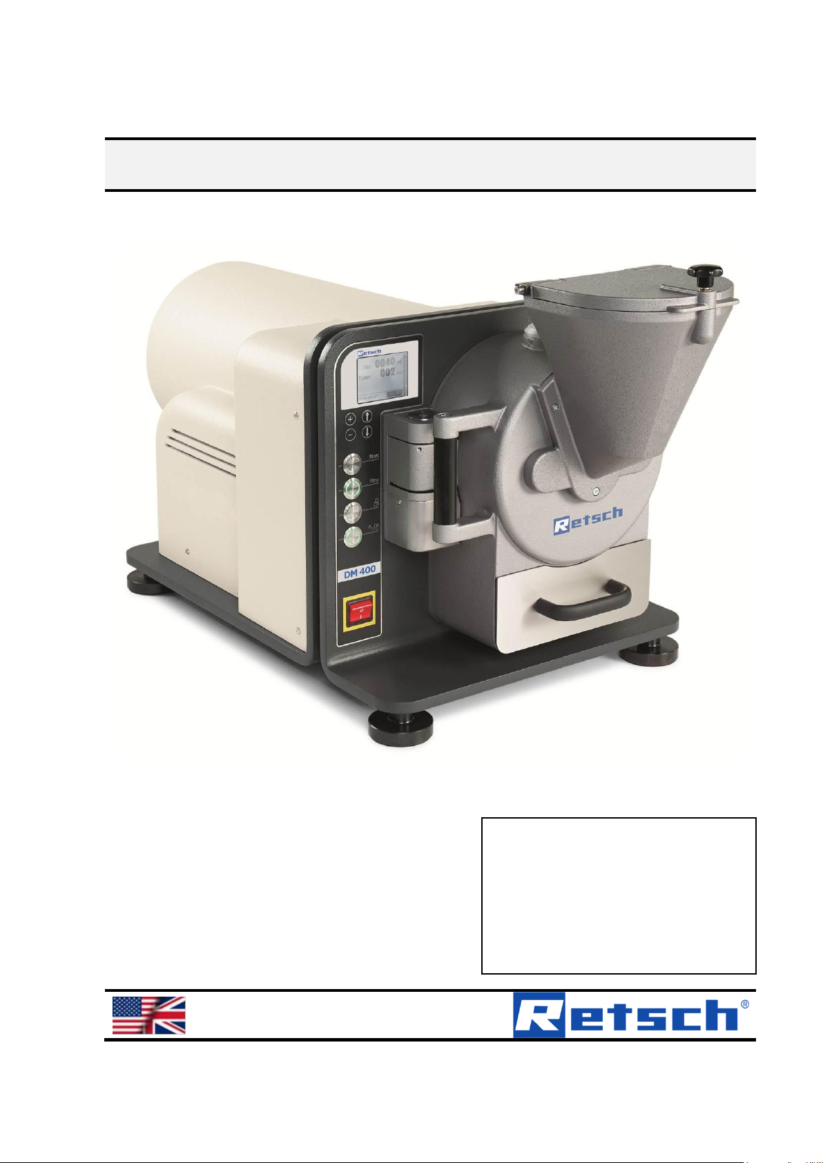
Operating Manual
DM400 Disc Mill
Original
© Retsch GmbH, 42781 Haan, Retsch-Allee 1-5, Germany 18.07.2014 0001
Page 2

Copyright
© Copyright by
Retsch GmbH
Haan, Retsch-Allee 1-5
D-42781 Haan
Federal Republic of Germany
Page 3

Page 4

Table of contents
4
1 Basic construction .................................................................................................................................. 7
2 Safety instructions and use ................................................................................................................... 9
2.1 Requirements for the user ................................................................................................................ 9
2.2 Intended use ................................................................................................................................... 10
2.2.1 Operating principle ..................................................................................................................... 10
2.3 Duties of the operating company.................................................................................................... 10
2.4 Hazard warnings and symbols used .............................................................................................. 11
2.5 Device safety instructions ............................................................................................................... 15
2.6 Safety equipment ........................................................................................................................... 17
2.7 Danger areas .................................................................................................................................. 18
2.8 Electrical safety .............................................................................................................................. 18
2.8.1 General information.................................................................................................................... 18
2.8.2 Protection against restarting ...................................................................................................... 19
3 Technical data ....................................................................................................................................... 21
3.1 Dimensions ..................................................................................................................................... 21
3.2 Weight ............................................................................................................................................ 21
3.3 Operating noise .............................................................................................................................. 21
3.4 Voltage, power consumption, power input ..................................................................................... 21
3.5 Fuse ................................................................................................................................................ 21
3.6 Material ........................................................................................................................................... 22
3.7 Final fineness ................................................................................................................................. 22
4 Installation ............................................................................................................................................. 23
4.1 Transport ........................................................................................................................................ 23
4.2 Unpacking ....................................................................................................................................... 23
4.3 Positioning ...................................................................................................................................... 24
4.4 Ambient conditions ......................................................................................................................... 25
4.5 Electrical connection ...................................................................................................................... 26
4.5.1 Adjusting the disc mill to the mains network .............................................................................. 26
4.6 Putting into service ......................................................................................................................... 26
4.7 Switching on for the first time / function test ................................................................................... 27
4.7.1 Switching on ............................................................................................................................... 27
4.7.2 Switching off ............................................................................................................................... 27
5 Working with the disc mill .................................................................................................................... 29
5.1 Display and control panel ............................................................................................................... 30
5.2 Menu navigation ............................................................................................................................. 30
5.3 Specifying the zero point ................................................................................................................ 31
5.4 Adjusting the gap width .................................................................................................................. 32
5.5 Reverse operation .......................................................................................................................... 33
5.6 Adjusting the grinding time ............................................................................................................. 34
5.7 Changing the language .................................................................................................................. 35
5.8 Grinding with zirconium oxide grinding discs ................................................................................. 35
5.9 Material feed ................................................................................................................................... 36
5.10 Sample removal.............................................................................................................................. 38
5.11 Final fineness ................................................................................................................................. 38
6 Cleaning ................................................................................................................................................. 39
6.1 Extracting dust after grinding .......................................................................................................... 39
6.2 Grinding chamber ........................................................................................................................... 39
6.3 Housing .......................................................................................................................................... 40
6.4 Cleaning the hopper ....................................................................................................................... 40
Page 5

Table of Contents
5
7 Servicing ................................................................................................................................................. 41
7.1 Grinding discs ................................................................................................................................. 42
7.2 Replacing the grinding discs (5 + 6)................................................................................................ 42
7.3 Replacing the gear oil ..................................................................................................................... 49
7.3.1 Conducting the gear oil change .................................................................................................. 49
8 Repair ...................................................................................................................................................... 51
8.1 Checklist for troubleshooting ........................................................................................................... 52
9 Disposal .................................................................................................................................................. 54
10 EC Declaration of Conformity ............................................................................................................... 55
11 Index ........................................................................................................................................................ 57
Page 6

Table of contents
6
Page 7
Basic construction
7
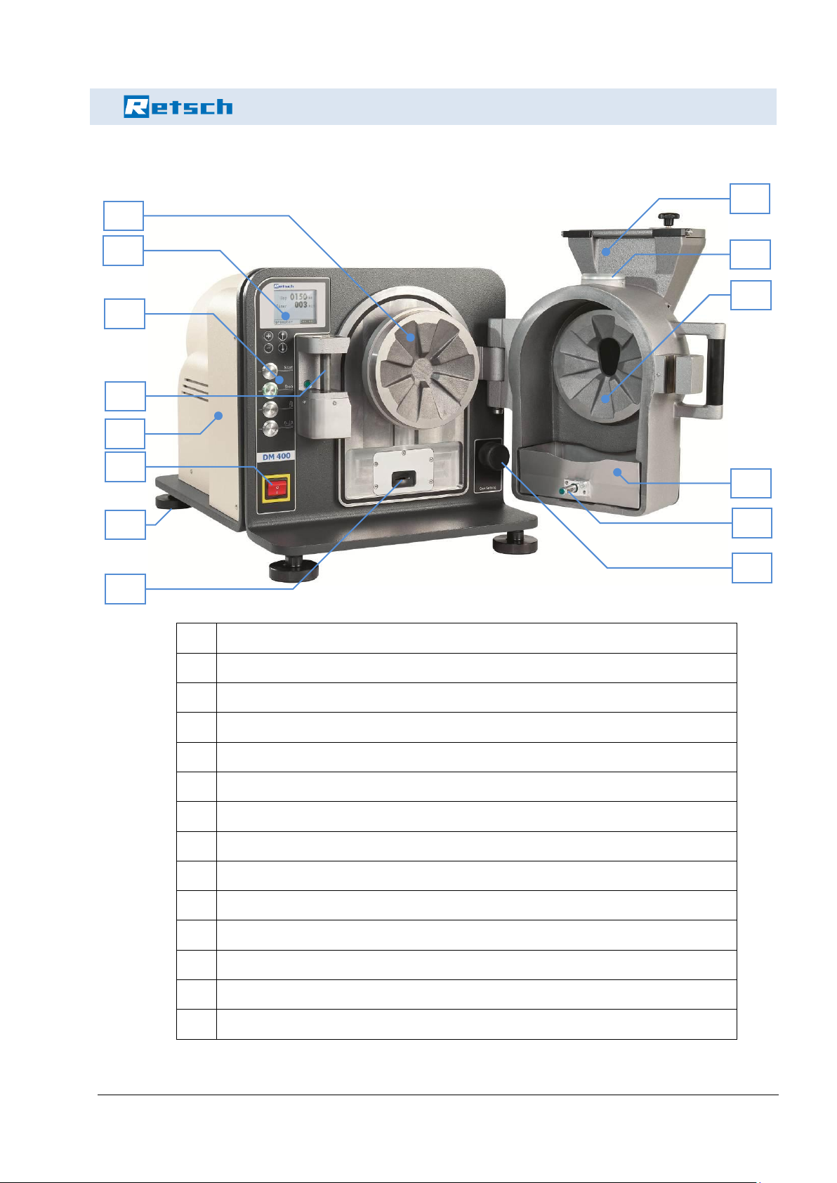
1 Basic construction
1
Display
2
Control panel
3
Main switch
4
Fill hopper
5
Fixed grinding disc
6
Moving grinding disc
7
Gap set screw
8
Grinding chamber closing mechanism
9
Locking bolts sample material container
10
Sample material container
11
Suction flange lid
12
Height adjustable support
13
Interlock switch
14
Housing cover
1
2
12
10
6
13
3
9 5 4
11 7 8
14
Page 8
Basic construction
8
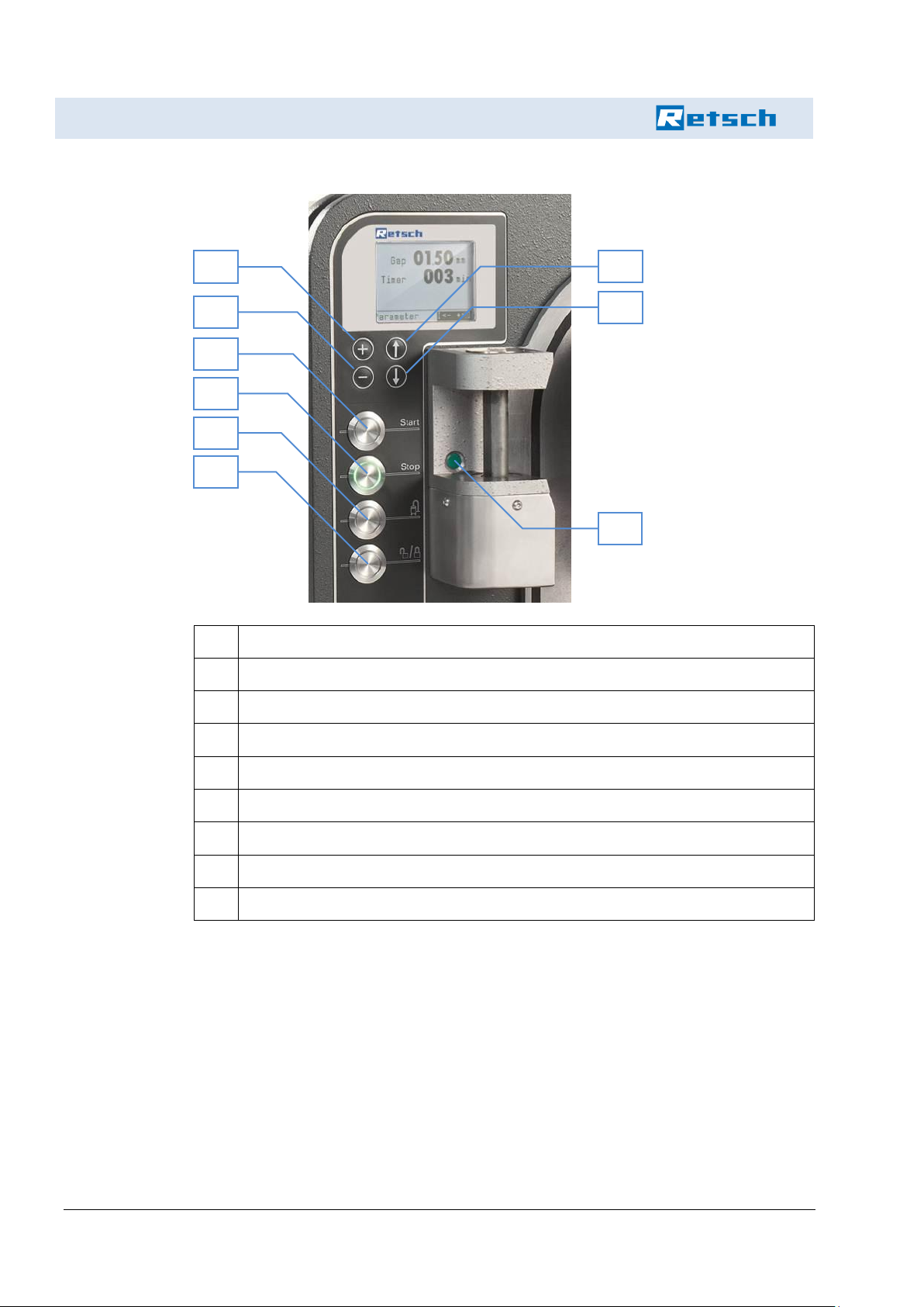
a
+ button (change parameters and gap width, menu navigation)
b
- button (change parameters and gap width, menu navigation)
c
Arrow up button (menu navigation)
d
Arrow down button (menu navigation)
e
Start button
f
Stop button
g
Button dust extraction (on/off)
h
Unlocking and locking the grinding chamber
i
Sensor grinding chamber
a b c d e f g h i
Page 9

Safety instructions and use
9
This Operating Manual is intended for persons commissioned with
the operation and monitoring of the DM400. The Operating Manual,
and in particular the safety instructions, should be heeded by all persons working on or with the equipment. Furthermore the regulations
and provisions on accident prevention applicable at the application
site must be observed. The Operating Manual must always be kept
where the DM400 is used.
Persons with health disorders or who are under the influence of medication, drugs, alcohol or extreme tiredness must not operate the device.
The DM400 may only be operated by authorised persons and serviced and repaired by trained specialists. Technically qualified personnel must conduct all maintenance, servicing and repair work!
Qualified personnel are people who have been authorised by persons
responsible for the safety of the system to execute the required activities and are able to recognise potential dangers and avoid them
based on their training, experience and instruction, as well as their
knowledge of relevant standards, regulations, accident prevention
regulations and operating conditions (definition of skilled personnel
according to IEC 364).
The instructions in this Manual should be followed in order to prevent
danger to the user.
Faults which can impair the safety of persons, the DM400 or other
material assets should be rectified immediately. The following instructions serve both personal safety of operating staff and the safety of
the described products as well as connected equipment: all servicing
and repair work may only be carried out by technically qualified personnel!
This Operating Manual is not a full technical description. It only describes information required for safe operation and maintenance of
serviceability.
Retsch has prepared and checked this Operating Manual very carefully. However no liability can be assumed regarding completeness and
accuracy.
Subject to technical amendments.
2 Safety instructions and use
2.1 Requirements for the user
Page 10
Safety instructions and use
10
2.2 Intended use
The DM400 is a disc mill for batch or continuous fine grinding of hard
brittle to medium hard solids from the areas of mining and metallurgy,
geology and mineralogy and the glass and ceramics industry.
The maximum feed size is 20 mm edge length; the achievable final
fineness level depending on the gap width set is approx. 12 mm (largest gap width) and 0.05 mm (smallest gap width).
The material throughput of the disc mill lies in the range of 20 to 150
kg/h. This depends on the setting of the outlet gap and the bulk
weight and grinding conduct of the sample.
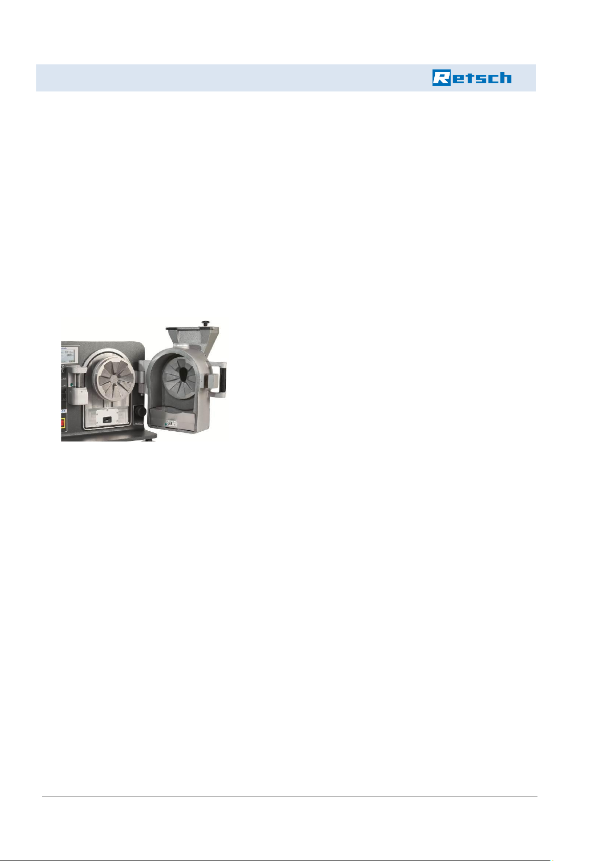
The grinding of the material sample takes place in a grinding
chamber which is dustproof to the outside and in which two
coarsely toothed grinding discs operate against each other.
The moving grinding disc is driven by a powerful, slow running
gear motor.
The sample material is filled through a lockable hopper into the
centre of the upright grinding disc and, after being ground by
compression and shear stress, escapes through the gap between the two discs. The gap width determines the mean particle size of the sample material. The grinding gap can be set to
an accuracy of 0.05 mm using the plus/minus buttons on the
control panel. The gap width can be read off the display (1).
When grinding batches, the sample material is collected in a
sample material container placed in the device (volume: 2l).
The closed design prevents dust escaping. A dust extraction
device may additionally be connected. To clean, the front housing is opened sideways - the grinding chamber is then freely
accessible.
This Manual should be read and understood before using the DM400.
Use of the DM400 demands expert knowledge and should be limited
to commercial users.
Operating personnel must be familiar with the contents of the Operating Manual. It is therefore very important for this Operating Manual to
be actually handed to these persons. It must be ensured that the
Operating Manual always remains with the device.
The DM400 may be used exclusively within the possible uses set out
in this Manual and within the specified regulations in this Manual. In
the event of contravention or incorrect use, the customer assumes full
2.2.1 Operating principle
2.3 Duties of the operating company
Page 11
Safety instructions and use
11
liability for the functionality of the DM400 or for damage arising from
an infringement of this duty.
Through use of the DM400 the customer agrees and recognises that
defects, faults or errors cannot be entirely ruled out. In order to avoid
the risk of personal injury or damage to property arising from this or
otherwise or of other indirect or direct damage, customers must take
adequate and comprehensive safety measures when working with the
device.
It is not possible for Retsch GmbH to monitor compliance with this
Manual or the conditions and methods used in the installation, operation, use and servicing of the DM400. Damage to property leading to
danger to persons may result from incorrect installation. We therefore
assume no responsibility and liability at all for loss, damage or costs
arising from or in any way associated with faulty installation, incorrect
operation or from incorrect use and servicing.
The applicable accident prevention regulations must be complied with.
Generally accepted statutory and other binding regulations on envi-
ronmental protection must be observed.
Safety instructions
Safety instructions are indicated in this Manual by symbols. The safety instructions are introduced by signal words which express the degree of danger.
DANGER!
This combination of symbol and signal word indicates a
direct hazardous situation leading to death or serious
injuries if it is not avoided.
WARNING!
This combination of symbol and signal word indicates a
potentially hazardous situation which can lead to death
or serious injuries if it is not avoided.
2.4 Hazard warnings and symbols used
Page 12

Safety instructions and use
12
CAUTION!
This combination of symbol and signal word indicates a
potentially hazardous situation which can lead to minor
or slight injuries if it is not avoided.
NOTICE!
This combination of symbol and signal word indicates a
potentially hazardous situation which can lead to
damage to property if it is not avoided.
NOTICE!
This combination of symbol and signal word indicates a
potentially hazardous situation which can lead to
damage to the environment if it is not avoided.
Page 13
Safety instructions and use
13
Special safety instructions
The following symbols are used in safety instructions to alert to specific hazards:
DANGER!
This combination of symbol and signal word indicates a
direct hazardous situation through electric current. If a
sign with this symbol is not heeded, serious or fatal
injuries will result.
DANGER!
This combination of symbol and signal word designates
content and instructions for intended use of the machine
in potentially explosive areas. If a sign with this symbol
is not heeded, serious or fatal injuries will result.
DANGER!
This combination of symbol and signal word designates
content and instructions for intended use of the machine
with flammable materials. If a sign with this symbol is
not heeded, serious or fatal injuries will result.
DANGER!
This combination of symbol and signal word designates
content and instructions for intended use of the machine
with potentially explosive substances. If a sign with this
symbol is not heeded, serious or fatal injuries will result.
WARNING!
This combination of symbol and signal word indicates a
direct hazardous situation due to moving parts. If a sign
with this symbol is not heeded, injuries to hands may
result.
Page 14
Safety instructions and use
14
WARNING!
This combination of symbol and signal word indicates a
direct hazardous situation due to hot surfaces. If a sign
with this symbol is not heeded, skin contact with hot
surfaces may cause serious burns to skin.
Safety instructions in
operating instructions
Safety instructions may refer to a specific, individual operating instruction. Such safety instructions are embedded in this operating instruction in order not to interrupt the flow of reading when performing the
action concerned. The signal words described above are used.
Example:
1.
Loosen screw.
2.
CAUTION!
Risk of pinching on the lid.
Close the lid carefully.
3.
Tighten the screw.
Tips and recommendations
This symbol highlights useful tips and recommendations
as well as information for efficient and fault-free
operation.
Other labelling
The following labels are used to emphasise operating instructions,
results, lists, references and other elements in this Manual:
Labelling
Explanation
1., 2., 3. ...
Step-by-step operating instructions
Results of operating steps
Lists without specified order
[Button]
Control elements (e.g. button, switch), indicators (e.g. signalling lamps)
"Display"
Screen elements (e.g. buttons, assignment
of function buttons)
Page 15

Safety instructions and use
15
2.5 Device safety instructions
Please note!
Only use original accessories and original spare parts. Failure to
do so can place the protection of the machine in doubt.
Safe conduct must be strictly followed during all work.
The current applicable national and international accident
prevention regulations must be complied with.
Page 16
Safety instructions and use
16
CAUTION!
Wear hearing protection!
Hearing protection should be worn when a noise level of
85dB (A) is reached or exceeded in order to prevent
damage to hearing.
WARNING!
The maximum workplace concentrations (threshold limit
values - TLV) in valid safety regulations must be
observed, and ventilation must be provided where
necessary or the machine operated under an extractor
hood.
DANGER!
Risk of explosion!
- When grinding oxidable substances (e.g. metals or
coal) there is a risk of spontaneous ignition (dust
explosion) if the fine fraction exceeds a certain
percentage. For this reason special safety measures
must be taken when grinding such substances and
the work must be supervised by a specialist.
- The device is not designed for use in potentially
explosive areas and is not suitable for grinding
explosive materials.
Do not remove signs.
NOTICE!
Replace damaged or illegible signs without delay.
Unauthorised modifications to the device lead to loss of the
conformity to European directives declared by Retsch and to loss
of the warranty claim.
Only use the DM400 in a technically perfect state and as intended,
with an awareness of safety and dangers as specified in the
Operating Manual. In particular have faults which might impair
safety rectified immediately!
If you have any questions or problems after reading the Operating
Manual, please contact our technical staff.
Page 17
Safety instructions and use
17
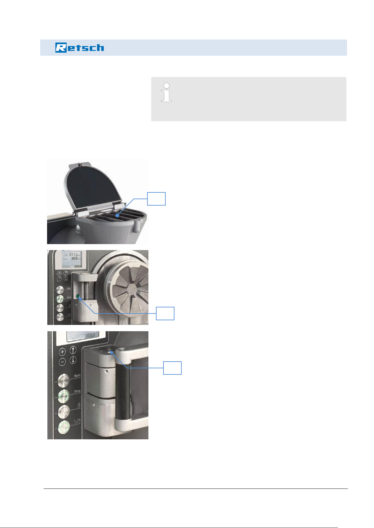
2.6 Safety equipment
Safety equipment must be used as intended and must
not be rendered unworkable or removed.
All safety equipment must be checked regularly for
completeness and function.
The disc mill has a comprehensive safety system:
1.
A grille (4G) prevents contact with the fill hopper (4).
2.
A sensor (i) monitors the closing of the grinding chamber before
operation and prevents the disc mill starting up after it has been
opened.
3.
A second safety device checks whether the grinding chamber has
been closed by means of the motorised closing mechanism (8).
4G i 8
Page 18
Safety instructions and use
18
4.
The interlock switch (13) pulls in the sample material container
after the start of grinding and locks it using the locking bolt (9) on
the container. During operation the interlock switch monitors
whether the device is closed correctly. It likewise prevents the
disc mill starting up after it has been opened.
The disc mill does not start if the grinding chamber
is open or the sample material container is missing.
CAUTION!
- Risk of crushing on hopper cover
- Risk of crushing when closing the grinding chamber
- Risk of crushing when cover of dust extraction is
removed during operation!
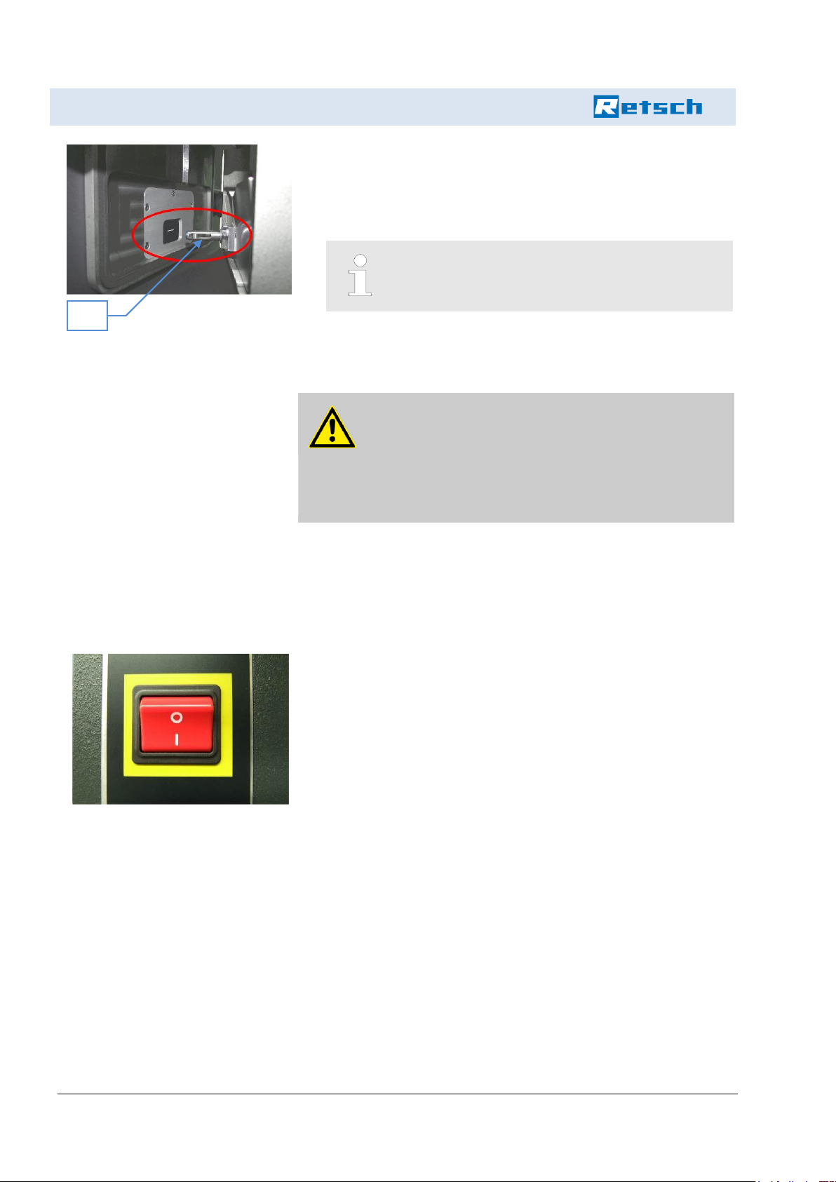
The disc mill is switched on and off with a main switch (3).
By pressing the switch to I (On):
Disc mill is activated and can be started using the start button (e)
as long as the grinding chamber is closed and the sample material
container is inserted!
By pressing the switch to O (off) during grinding:
The disc mill comes to a halt and is completely deactivated!
Grinding chamber and sample material container remain locked
when switched “off” and cannot be opened.
13
2.7 Danger areas
2.8 Electrical safety
2.8.1 General information
Page 19

Safety instructions and use
19
2.8.2 Protection against restarting
The device switches off in the event of a power failure during operation.
The mill comes to a halt within seconds!
Sample material container can only be opened with the emergency
release (k) inside the device! To do this the housing cover (14)
must be removed as follows (also see chapter “Positioning” )
DANGER!
Pull the plug out and secure the device to prevent
accidental restarting!
Open the housing cover (14) by releasing the quick acting
screws placed on either side.
After releasing the quick acting screws, pull the housing cover
(14) back by a few centimetres. Then lift the housing cover up
and out.
The emergency release (k) inside the device is then visible.
To release the sample material container, pull the emergency
release (k) backwards until the locking bolt (9) on the sample
material container (10) is released.
Considerable force is required to release it.
The emergency release can then be engaged again and the
housing cover closed. The sample material container is pulled in
when grinding next starts.
NOTICE!
Grinding chamber cannot be opened when the grinding
chamber interlock is closed or when switched off.
The disc mill does not start up by itself when supply voltage returns.
The mill has protection against restarting.
The motor is started again by pressing the start button (e), and the
mill begins operation.
Page 20

Safety instructions and use
20
Page 21

Technical data
21
3 Technical data
52 x 105 x 63 cm (width x depth x height)
228 kg (net) without griding discs
246 kg with tungsten carbide grinding discs
Workplace related emissions value in accordance with DIN EN ISO
3746:2005 LPA .
= 68.9 dB (A) The measurement was conducted with sand as sample
material, particle size 0.5 – 2 mm.
Voltage
400V / 3~ 50Hz
230V / 3~ 60Hz
Power consumption
3.2 A
5.6 A
Power input
1830 W
Under high load (significantly
lower in normal use)
1800 W
Under high load (significantly
lower in normal use)
The device may only be operated on a three phase supply network!
Transient electrical surges according to surge category II permissible
(also see chapter “Electrical connection”)
A thermal circuit breaker (motor circuit breaker) is integrated in the
main switch (3) and triggers on overheating; it is operational again
after a brief cooling phase.
3.1 Dimensions
3.2 Weight
3.3 Operating noise
3.4 Voltage, power consumption, power input
3.5 Fuse
Page 22

Technical data
22
3.6 Material
Maximum feed size 20mm (depending on the material)
Minimum feed quantity 20 - 30ml
Batch grinding with collecting container (max. 2l)
Maximum throughput 150kg/h with continuous grinding
The final fineness is between 0.05 and 12mm, depending on the sample material.
3.7 Final fineness
Page 23

Installation
23
4 Installation
The device is supplied on a transport pallet with wooden cover. We
recommend transporting the packaged device with a pallet truck or
forklift.
DANGER!
Do not walk under the transport pallet during transport.
WARNING!
Incorrect lifting can lead to injury or damage to property.
The machine should only be lifted using suitable
equipment and by appropriately qualified personnel!
Damage caused by incorrect transport does not justify any replacement or warranty claims.
Pull out the nails attaching the cover to the transport pallet. The
cover is the wooden box pulled over the transport pallet.
Lift the cover from the transport pallet.
CAUTION!
Risk of crushing!
Always lift with 2 people.
Compare the contents of delivery with your order.
4.1 Transport
4.2 Unpacking
Page 24

Installation
24
4.3 Positioning
DANGER!
Do not walk under the transport pallet during transport.
To position the disc mill you will need a crane or other suitable means
of transport as well as 2 carrying straps (not included with delivery)
with a minimum length of 40cm and loadbearing capacity of 500 kg.
CAUTION!
Weight of the disc mill is approx. 260 kg with grinding
discs (WC) and transport pallet!
NOTICE!
The disc mill must be placed on an even, stable surface.
It can be screwed to this or to a base plate.
1.
The disc mill is screwed to the transport pallet from underneath
using 3 screws. Loosen screws using a spanner wrench (17
mm).
2.
Open the housing cover (14) by unscrewing the quick acting
screws on either side.
14S
Page 25

Installation
25
3.
After unscrewing the quick acting screws, pull the housing cover
(14) back by a few centimetres.
Then lift the housing cover up and out.
4.
Two carrying lugs to attach the carrying straps are then visible.
5.
Attach the carrying straps to a crane or other auxiliary equipment.
6.
Now attach the carrying straps to the 2 carrying lugs provided.
7.
With the help of the crane, position the disc mill in the desired
place. Take care while positioning that the device does not swing
when hanging on the crane.
8.
Remove the carrying straps!
9.
Place the housing cover (14) back on and screw tight.
WARNING!
Mains voltage!
- The device may only be used inside.
- The surrounding air must not contain any conductive
dust.
4.4 Ambient conditions
Page 26

Installation
26
- Maximum relative humidity 80% for temperatures up
to 31°C, decreasing in a linear fashion to 50% relative
humidity at 40°C.
The room temperature must be between 5 and 40°C.
Height up to 2000m above sea level
Degree of pollution 2 in accordance with IEC 664.
Before connection, compare the voltage and current values on the
type plate with the values on the intended mains.
CAUTION!
Electrical as well as mechanical components may be
damaged by failure to heed to values on the type plate.
The DM400 is delivered with supply voltage adapted to suit your country.
The disc mill is supplied with mounted grinding discs. Before grinding
for the first time, check the desired gap width (see chapter “Adjusting
the gap width ”) The device is operational once you have positioned
the disc mill as described under chapter “Positioning“ and have connected the plug to the mains socket.
CAUTION!
- Grinding discs must not touch each other.
- The device may only be operated with mounted and
secured grinding discs.
- Smallest gap width 0.05mm
4.5 Electrical connection
4.5.1 Adjusting the disc mill to the mains network
4.6 Putting into service
Page 27

Installation
27
4.7 Switching on for the first time / function test
Only switch the device on when all work described as from the chapter “Installation” has been carried out!
Set the main switch (3) to I! The display (1) switches on and the
STOP button (f) is lit up in red! If the grinding chamber is locked, the
release and locking button (h) is lit up in green.
When the grinding chamber has been electrically closed and the sample material container is inserted, start using the start button (e). The
disc mill starts up. Then actuate the stop button (f), and the machine
comes to a halt. It is then possible to continue with the chapter “work-
ing with the disc mill”.
Set the main switch (3) to 0. The device switches off completely.
4.7.1 Switching on
4.7.1.1 Function test
4.7.2 Switching off
Page 28

Installation
28
Page 29

Working with the disc mill
29
WARNING!
No warranty or complaint will be accepted in the case of
damage to the device when grinding tools are used
which are not original accessories of the device.
WARNING!
Before starting the machine, ensure that the grinding
discs are correctly mounted and that there are no loose
parts inside the device. If this is not observed, no
warranty or complaint will be accepted for damage to the
device or personal injury that result.
CAUTION!
- Grinding discs must not touch each other.
- The device may only be operated with mounted and
secured grinding discs.
- Smallest gap width 0.05mm
CAUTION!
Ensure that the suction flange lid or adapter to use the
dust extractor are fitted securely. Never reach into the
opening of the suction flange during grinding
NOTICE!
Do not leave the disc mill to run unsupervised.
NOTICE!
Grinding discs wear during grinding. For this reason the
grinding gap must be checked and regulated if
necessary according to use and the degree of wear.
This is carried out as described in chapter 5.3
“Specifying the zero point” and in chapter 5.4 “Adjusting
the gap width”.
5 Working with the disc mill
Page 30

Working with the disc mill
30
5.1 Display and control panel
If the grinding chamber is open, the button (h) to lock the grinding
chamber is not lit up!
During the motorised closing of the grinding chamber, the button
(h) flashes green until the grinding chamber is closed. It is then lit
up in green.
When starting up, the start button (e) flashes green. When the
device has started up, it lights up in green.
After stopping the device, the stop button (f) flashes red until the
disc comes to a standstill. When it is at a standstill it lights up in
red.
When a dust extractor is connected, the button (g) lights up in
green after its activation.
The +/- buttons (a, b) are used to adjust values and for menu
changes.
The arrow buttons (c, d) are used to select menu items and to
make changes in the menu bar.
Menu selection
1.
The Parameter menu is used for the following:
‒ To adjust the gap width between the grinding discs → Gap
‒ To adjust the grinding time in minutes → Time
2.
In the Check/Setup menu you can:
‒ Define the “zero point” → no gap between the grinding discs
‒ Change the direction of rotation of the moving grinding disc (6)
→ Reverse
‒ Set the language → Language
5.2 Menu navigation
Page 31

Working with the disc mill
31
Menu change
1.
To move from the "Parameter" menu to the "Check/Setup" menu,
actuate the arrow buttons (c, d) until the - and + signs which are
visible on the bottom right of the display are highlighted in black!
Then use the buttons + (a) or - (b) to move to the Check/Setup
menu!
2.
The menu change from the Check/Setup menu to the Parameter
menu takes place in the same way.
Selecting menu items
1.
The menu items within menus are selected using the arrow buttons (c, d).
The zero point is the gap width at which the fixed and the
moving grinding disc rub slightly against each other so
that no gap is present. All other gap widths are actuated
from this zero point.
The zero point must be reset after every time the
grinding discs are changed. Grinding discs can vary in
thickness according to the degree of wear.
1.
To move from the "Parameter" menu to the "Check/Setup" menu,
actuate the arrow buttons (c, d) until the - and + signs which are
visible on the bottom right of the display are highlighted in black!
Then use the buttons + (a) or - (b) to move to the Check/Setup
menu!
2.
Close the grinding chamber and remove the sample material
container.
5.3 Specifying the zero point
Page 32

Working with the disc mill
32
3.
To change the grinding gap to adjust the zero point, the zero
point line must be selected in the Check / Setup menu using the
arrow buttons (c, d).
4.
Remove the suction flange lid (11). Check both grinding discs
while they are moving together through this opening. It should
only be possible to see a minimal light gap between the two
discs.
During the process of setting the zero point, no gap
information is shown on the display. You can hear a
mechanical noise of the servomotor and see how
the moving grinding disc (6) is aligned through the
suction flange (11)!
5.
CAUTION!
Risk of crushing between the grinding discs!
To check while adjusting the zero point, rotate the moving grinding disc by hand through the opening of the sample material container. While rotating, reduce the gap using the – button (b) until
slight rubbing of the two discs can be felt and heard!
6.
As soon as the smallest gap width has been set and a minimum
rubbing of the discs is registered, this may be defined as zero
point. Only when the zero point is highlighted in black can the
zero point be fixed by simultaneously pressing the stop (f) and +
(a) buttons.
7.
Reinsert the sample material container.
The adjustment of the gap width takes place automatically using the
Parameter menu item. The zero point must be set first (see chapter
“Specifying the zero point) to prevent damage to the grinding discs.
The gap width is adjusted as follows:
5.4 Adjusting the gap width
Page 33

Working with the disc mill
33
1.
To move from the "Check/Setup" menu to the "Parameter" menu,
actuate the arrow buttons (c, d) until the - and + signs which are
visible on the bottom right of the display are highlighted in black!
Then use the buttons + (a) or - (b) to move to the Parameter
menu
2.
Close the grinding chamber!
3.
In the Parameter menu, press the c button (arrow up) until the
line to enter the gap width is highlighted.
4.
Using the +/- buttons on the control panel, increase (+) or decrease (-) the gap width!
5.
The gap width between the discs adjusts automatically if:
☞the menu item is exited or
☞the grinding process is started using the start button (e).
NOTICE!
Grinding discs wear during grinding. For this reason the
gap width must be checked and possibly adjusted from
time to time. This takes place as described in the
chapter “Specifying the zero point and the chapter
“Adjusting the gap width ”.
CAUTION!
Risk of crushing between the grinding discs!
Reverse operation can be selected in the case of one-sided wear on
grinding discs.
5.5 Reverse operation
Page 34

Working with the disc mill
34
1.
To move from the "Parameter" menu to the "Check/Setup" menu,
actuate the arrow buttons (c, d) until the - and + signs which are
visible on the bottom right of the display are highlighted in black!
Then use the buttons + (a) or - (b) to move to the Check/Setup
menu!
2.
Select reverse using the arrow buttons (c, d), and activate (on) or
deactivate (off) reverse operation with + (c) or - (d) button.
NOTICE!
Grinding discs are subject to natural wear after
longer periods of use and must be replaced where
necessary. If you ascertain that the grinding discs
are worn on one side, they need not be replaced
immediately. Reverse the direction of rotation of the
drive motor using the reverse setting. The crushing
edges of the grinding discs that had been on the
back are then in use. At this point at the latest you
should order spare grinding discs (see chapter
“Replacing the grinding discs (5 + 6)”)
1.
To move from the "Check/Setup" menu to the "Parameter" menu,
actuate the arrow buttons (c, d) until the - and + signs which are
visible on the bottom right of the display are highlighted in black!
Then use the buttons + (a) or - (b) to move to the Parameter
menu!
5.6 Adjusting the grinding time
Page 35

Working with the disc mill
35
2.
Select the Time menu item using the arrow buttons (c, d) and
then adjust using the + / - button. If no grinding duration has
been specified, the grinding can be started and ended manually
using the start - (e) and stop- (f) button. The maximum timecontrolled grinding duration that can be set is 60 min!
1.
To move from the "Parameter" menu to the "Check/Setup" menu,
actuate the arrow buttons (c, d) until the - and + signs which are
visible on the bottom right of the display are highlighted in black!
Then use the buttons + (a) or - (b) to move to the Check/Setup
menu!
2.
Select the language line using the arrow buttons (c, d). The language (German or English) can be selected using the +/- button
and then set by exiting the menu item.
A number of points must be observed when grinding using zirconium
oxide grinding discs:
1.
Precise adjustment of the zero gap. Under no circumstances
may the discs touch each other during grinding. The localised
heating leads directly to stress cracks on the perimeter. These
cracks occur in a very short time and are easily identified.
2.
Localised heating can also occur if you add so much material that
high pressure grinding takes place permanently in the grinding
gap on the outer edge of the grinding discs. The leads to stress
cracks on the perimeter of the grinding disc or even to it breaking.
5.7 Changing the language
5.8 Grinding with zirconium oxide grinding discs
Page 36

Working with the disc mill
36
3.
The hardness of the zirconium oxide grinding disc is MOHS 8.5
(HV1350). No sample material that is harder may be ground
because this causes the outer edges of the grinding disc to chip.
Chipping of the edges can also occur with a sample material with
MOHS hardness of 6 or 7.
4.
Proceed very carefully when grinding using zirconium oxide
grinding discs. You should pre-grind your sample material with a
large gap width in the first run before achieving the desired fineness with the smallest gap in a second run. You should proceed
in a similar way if you have no information about the grindability
of your material. The grinding discs have a progressive chipping
geometry. Coarse grinding takes place in the inner area, and fine
grinding in the outer area of the grinding disc. The strain is
greatest in the fine grinding area. The chipping described may
occur here with very hard sample material.
5.
The adhesive used to adhere the securing bolts in the grinding
disc has a temperature resistance up to 80°C. The grinding discs
should therefore not be heated above 80°C in order to guarantee
the secure fit in the support.
6.
Please observe the chapter “Replacing the grinding discs (5 + 6)”
in the Operating Manual when assembling and removing the
grinding discs!
NOTICE!
Retsch GmbH guarantees that only zirconium oxide
grinding discs of the highest quality leave our company.
Used grinding discs which are cracked, chipped or
completely broken on the perimeter, cannot be accepted
as complaint.
DANGER
Risk of explosion
There is a risk of spontaneous ignition (dust
explosion) when grinding substances which oxidise
(e.g. metals or coal) if the fine fraction exceeds a set
percentage. Special safety precautions must
therefore be taken when grinding such materials and
the work must be supervised by a specialist.
The device does not have an ex-protected design
and is not suitable for grinding explosive materials.
5.9 Material feed
Page 37

Working with the disc mill
37
Before switching the device on, care must be taken that
the grinding chamber is locked and the sample material
container is placed straight in the insert and is not
twisted!
CAUTION!
Switch the device on before filling material in the hopper.
1.
The cover of the hopper is secured by a quarter turn quick release fastener. To open the lid, turn the quick release fastener a
quarter turn in an anticlockwise direction!
2.
Fill the sample in the hopper
3.
Add only as much material as will allow the hopper cover to be
closed!
4.
To close the cover you must press the pins on the quick release
fastener into the grooves on the hopper and lock again with a
quarter turn in a clockwise direction!
5.
Monitor the grinding process (grinding noise) and determine the
optimum feed quantity! Repeat this with each new material.
6.
Only add more material once the grinding noise has reduced!
7.
The maximum feed quantity depends on the grindability of the
material and the collecting volume of the sample material container.
8.
Place large lumps of material (max. 20mm edge length) individually in the hopper, close the cover and secure!
Page 38

Working with the disc mill
38
5.10 Sample removal
NOTICE!
The grinding disc support and the housing are made
from ductile cast iron. This cast steel is not rustproof. If
you grind slightly damp sample material, after grinding
you must dry the back of the grinding disc, the inside of
the grinding disc support and all parts of the housing
which come into contact with the sample. If you do not
do so, corrosion can be expected to occur.
Depending on the volume of the ground material, care
must be taken when removing the sample material
container (10) to remove it with both hands. Risk of tipping
over!
The achievable final fineness depends on the property of the sample
and the selected gap width (approx. 0.05 mm to approx. 12 mm).
Only one dimension of the individual particles in the fine material is
determined by the gap width, e.g. the material crushed in platelet form
in the fine product may well contain larger dimensions in an expansion
direction. Normally, however, after a second run with such materials,
the proportion of the sample with larger dimensions in this expansion
direction will have decreased significantly.
5.11 Final fineness
Page 39

Cleaning
39
6 Cleaning
DANGER!
Mains voltage!
- Before starting cleaning work, unplug the device and
protect it from restarting accidentally!
- Do not let liquid run into the device.
- Indicate cleaning work using a warning sign.
- Put safety equipment back into operation after
cleaning work.
NOTICE!
The grinding disc support and the housing are made
from ductile cast iron. This cast steel is not rustproof. If
you grind slightly damp sample material, after grinding
you must dry the back of the grinding disc, the inside of
the grinding disc support and all parts of the housing
which come into contact with the sample. If you do not
do so, corrosion can be expected to occur.
After completion of the grinding process, you can vacuum the dust
created during grinding.
NOTICE!
Do not switch on the dust extraction during grinding as
sample material may otherwise also be extracted.
To clean the grinding chamber, open the chamber. Clean the chamber using a brush and vacuum cleaner. Where necessary you can
also use liquid detergents (alcohol, benzene). However pay attention
to any rust if you use aqueous liquids.
It is important to allow the disc mill to dry completely.
6.1 Extracting dust after grinding
6.2 Grinding chamber
Page 40

Cleaning
40
WARNING!
Risk of poisoning and fire!
When using detergents which are flammable or harmful
to health, it is essential to heed the valid safety
regulations (TLV) and where applicable to clean the disc
mill in a ventilated safety zone.
The machine can be cleaned outside when switched off using a soft
damp cloth. A solution of water and mild detergent may be used here.
No not use a solvent for cleaning.
In special cases the hopper may also be removed and cleaned as
described in the chapter “Replacing the grinding discs (5 + 6)”. When
grinding with the same sample, it is sufficient to clean the hopper of
dirt using a brush and dust extraction. For more intensive cleaning,
the protective grille can be removed by unscrewing 4 M3 countersunk
screws. Clean the hopper with the help of a damp cloth!
CAUTION!
Mount the grille again after cleaning!
Never operate the disc mill without hopper or hopper
grille!
6.3 Housing
6.4 Cleaning the hopper
Page 41

Servicing
41
DANGER!
Mains voltage
- Before starting servicing work, unplug the device and
protect it from restarting accidentally!
- Indicate servicing work using a warning sign.
- Only have servicing carried out by skilled personnel.
- Put safety equipment back into operation after
servicing and repair work.
- We recommend keeping a safety logbook into which
all work (servicing, repairs etc.) to the device are
entered.
- The most important element of servicing is regular
cleaning:
- Cleaning of the entire device must observe the
regulations of the employer’s liability insurance
associations (BGV A3) – in particular when the device
is positioned in a dusty environment or dusty sample
material is processed.
7 Servicing
Page 42

Servicing
42
Function part
Task
Test
Service interval
Grinding chamber sensor
Start inhibitor
Open grinding chamber; start; error message
Always before use
Grinding chamber safety interlock
Start inhibitor
Do not close grinding
chamber electrically;
start; error message
Always before use
Grinding container
protective equipment
Start inhibitor
Sample material container not inserted;
start; error message
Always before use
Grinding disc gap width
Crush function
Check distance
Always before use
The grinding discs wear after a certain period of time according to
sample material. Check the surfaces at specific intervals. Refer to
the information in the chapter “Reverse operation” and the chapter
below “Replacing the grinding discs (5 + 6)” to change the direction of
rotation or to replace the discs.
CAUTION!
The device must be connected to the mains to open the
grinding chamber and to adjust the gap width.
7.1 Grinding discs
7.2 Replacing the grinding discs (5 + 6)
Page 43

Servicing
43
CAUTION!
- Risk of crushing when changing the grinding discs.
- When changing grinding discs, secure them to
prevent them falling down.
CAUTION!
Before inserting the new discs, clean the support and the
back of the discs thoroughly. This is in particular very
important when using the ZrO2 discs and also with
TC+CO discs, so that the discs are positioned without
tension and parallel to each other.
It is also important when tightening the screws that the
tightening torque is not too great (see table) and is the
same for both screws.
Rubber washers (I) which are placed under the steel
washers are used with ZrO2 grinding discs. The nuts are
then tightened until the rubber washer slightly squeezes
out beneath the steel washer. This ensures a tightening
torque of approx. 20Nm.
NOTICE!
When replacing grinding discs, hold them securely and
do not allow them to fall. In the case of zirconium oxide
discs, this can lead to breakage or chipping.
Tools required:
M20 spanner wrench (r)
Motor shaft retainer (s)
30 mm ratchet wrench (t)
6
5
Page 44

Servicing
44
DANGER!
Ensure that the plug is removed from the socket again
after step 5!
1. Connect the device to the power supply!
2.
3.
Switch the main switch (3) to I (ON)!
To ensure that the hexagon screws at the back of
the movable grinding disc can be reached, the
grinding gap should be moved to the smallest width
(see chapter “Adjusting the gap width”)
4.
Then press the release button (h) on the control panel.
5.
The grinding chamber interlock (8) is released! Now open the
grinding chamber. The grinding discs are visible. The moving
grinding disc (6) is screwed at the back with 2x M20 hexagon
screws.
DANGER!
Pull the plug out and secure the device to prevent
accidental restarting!
6.
In order to be able to remove the moving grinding disc, the housing cover (14) must be removed (see chapter “Positioning”)
3
Page 45

Servicing
45
7.
8.
Then hold the motor shaft in place with the help of the motor shaft
retainer (s).
CAUTION!
Do not lock the motor shaft retainer (s) by resting on
the component!
NOTICE!
Hold grinding discs securely when changing them and
do not let them fall. This can lead to breaking or
chipping in the case of zirconium oxide discs.
CAUTION!
Risk of crushing when changing the grinding discs.
Ensure that the grinding disc does not fall on the
floor.
Using the spanner wrench (r), unscrew the hexagon screw on the
moving grinding disc and remove.
Page 46

Servicing
46
9.
The fill hopper (4) must be removed to dismantle the fixed grinding disc (5).
10.
To do this, manually close the grinding chamber and remove the
3 cylinder screws shown.
11.
Remove hopper from the front.
The mounting screws on the fixed grinding disc are then visible!
Page 47

Servicing
47
12.
DANGER!
Risk of crushing when changing the grinding discs.
Ensure that the grinding disc does not fall on the
floor.
Loosen the 2x M20 mounting screws using the ratchet wrench
and open the grinding chamber. Hold the grinding disc in place.
Remove the hexagon screws and remove the grinding disc.
13.
Now take the replacement moving grinding disc and assemble
with the hexagon screws (see Point 5 + 6 in reverse order)
14.
15.
16.
Install the housing cover
Connect the mains plug again.
Switch the device on!
17.
18.
19.
20.
Close the grinding chamber electrically
Adjust the grinding width to at least 12mm as described in the
chapter “Adjusting the gap width”!I
Unlock the grinding chamber and unplug the device!
DANGER!
Pull the plug out and secure the device to prevent
accidental restarting!
Insert the replacement fixed grinding disc and secure with the
hexagon screws. Manually close the grinding chamber and secure the disc using the ratchet wrench (t).
21.
Secure the hopper again in reverse order (see Points 10 and 11)
22.
Plug in and lock the grinding chamber again with the help of the
locking button (h).
Zero point must be specified again (see the chapter
“Specifying the zero point”)
Page 48

Servicing
48
Material
Max. guide
value tightening
torque (Nm)
Density
g/cm³
Abrasion
resistance
Use for sample
material
Hardened steel 1112% Cr
At least 50
7.9
Good
Hard, brittle samples
Manganese steel
12-13% Mn
At least 50
7.9 - 8
Good
Hard, brittle samples
Tungsten carbide
90.3% TC + 9.5%
CO
At least 50
14.8
Very good
Hard, abrasive samples
Zirconium oxide
92.5 ZrO2
Approx. 20
5.9
Extremely good
Medium hard, abrasive
samples for iron-free
grinding
Page 49

Servicing
49
The gearbox of the motor is filled with gear oil on delivery (ISO VG
220). A removable fill screw (o) is present in the top of the gearbox
housing to change the gear oil. To reach this the housing cover must
be removed.
This oil must be changed after approx. 5 years.
1.
Run the DM400 for approx. 15 minutes so that the gear oil inside
warms up and drains off better.
2.
3.
Switch the device off and unplug.
DANGER!
Pull the plug out and secure the device to prevent
accidental restarting!
Unplug the device and remove the cover (see chapter “Position-
ing”)
4.
Remove the motor securing screw (m) under the oil drain plug (n)
using an M10 Allen key!
The gearbox contains approx. 0.22 litres of ISO VG
220 gear box oil!
7.3 Replacing the gear oil
7.3.1 Conducting the gear oil change
Page 50

Servicing
50
5.
Hold a flat container underneath the oil drain plug (n) and unscrew this using an Allen Key No. 5 until oil flows out.
6.
Allow all of the oil to drain from the gearbox (approx. 0.22 l).
Watch the size of the collecting container and empty at intervals
where necessary, screwing the oil drain plug back in to do so.
7.
When the gear oil has been completely emptied, remove the oil
drain plug!
8.
Wipe any spilt gear oil with a paper towel and clean the contact
surface of the oil drain plug.
9.
Screw the oil drain plug with washer tight again.
10.
Assemble the motor securing screw again
11.
The fill screw (o) is then removed!
12.
Place a funnel in the hole and fill the gearbox with 0.22 litres of
gear oil ISO VG 220.
13.
Screw the fill screw (o) with clean sealing ring tight again.
14.
Assemble the housing cover.
Page 51

Repair
51
8 Repair
DANGER!
Mains voltage!
- Before starting repair work, unplug the device and
protect it from restarting accidentally!
- Indicate repair work using a warning sign.
- Have all repair work conducted by skilled personnel.
- Put safety equipment back into operation after
servicing and/or repair work.
Page 52

Repair
52
8.1 Checklist for troubleshooting
Malfunction
Possible cause
Rectification of fault
Mill does not start
No mains connection
Plug in
Mains switch is off
Switch the mains switch on
Grinding chamber safety switch open
Correctly connect the grinding chamber
Sample material container safety switch
open
Correctly insert the sample material container
Thermal circuit breaker has triggered
Wait until the device has cooled down
Fuse in the control circuit has triggered
Have the fuse replaced by qualified specialists.
Discs do not rotate
Gap width set to 0
Adjust the gap width! See chapter “Working with
the disc mill”
Sample is blocking the disc
Open grinding chamber and remove the sample
Mill stands still during operation
Overload! Switch off by motor circuit
breaker switch (main switch)
Allow the mill to cool. Remove sample material,
reduce feed of sample material
Grinding chamber overfilled. Too large /
hard sample material has become stuck
Open the grinding chamber and empty
Mill produces poor grinding
result
Grinding discs are worn
Change the direction of rotation or replace grinding discs. See chapter “Reverse operation” or
chapter “Replacing the grinding discs (5 + 6)“
Grinding discs are not installed in parallel
Remove grinding discs, clean the support and
reinsert (see chapter “Working with the disc mill” )
Sample materials escapes
Grinding chamber seals and sample
material container seals dirty or faulty
Clean or replace seals
Collecting container overfilled (max. 2l)
Remove container and clean the inside
Error message sample material
container
Sample material container not recognised
Slide container in centrally
Soiling of the container guide
Cleaning
No release of the sample
material container after STOP
Release mechanism on sample material
container faulty
Release by emergency actuation inside the
device; see chapter “Protection against restart-
ing”. Contact Retsch!
Automatic gap adjustment not
possible
Control panel is faulty
Replace the control panel
Gap adjustment is faulty
Contact Retsch
Temporary problem solution using the set screw
(7) on the bottom right-hand side at the front!
Adjust the precise gap width manually!
Discs have got stuck
With the help of the set screw (7), loosen! Realign the zero point!
Error message
Gap width, grinding chamber, sample
material container
Actuate the STOP button
Page 53

Repair
53
Page 54

Disposal
54
9 Disposal
Observe the respective statutory regulations when disposing of the device.
Information on disposal of electrical and electronic devices in the European Community:
The disposal of electrical equipment within the European Community is
specified by national regulations based on EU Directive 2002/96/EC on
Waste Electrical and Electronic Equipment (WEEE).
Accordingly all equipment supplied after 13.08.2005 in the business-tobusiness area may no longer be disposed of with the municipal or
household waste. They are labelled as follows to document this:
Fig. 1: Disposal label
Since the disposal regulations may differ from one country to an-
other within the EU, we ask you to contain your supplier where
necessary.
In Germany this labelling duty has applied since 23.03.2006. As
from this date the manufacturer must offer a reasonable possibility
for returning all equipment supplied as from 13.08.2005. The last
user is responsible for correct disposal for all equipment delivered
before 13.08.2005.
Page 55

EC Declaration of Conformity
55
10 EC Declaration of Conformity
Page 56

EC Declaration of Conformity
56
Page 57

Index
57
11 Index
A
Accident prevention .............................................. 9
Adapting to the mains network ........................... 26
Adjusting the gap width ...................................... 32
Adjusting the grinding time ................................. 34
Authorised persons ............................................... 9
B
Basic construction ................................................ 7
C
Changing the language ...................................... 35
Checklist for troubleshooting .............................. 52
Cleaning after grinding ....................................... 39
Cleaning the grinding chamber .......................... 39
Cleaning the hopper ........................................... 40
Cleaning the housing .......................................... 39
Control panel ...................................................... 30
D
Dimensions ......................................................... 21
Display ................................................................ 30
Disposal label ..................................................... 54
E
Electrical connection ........................................... 26
Electrical safety .................................................. 18
Explanation of signs ........................................... 11
M
Material feed ....................................................... 36
Menu change ...................................................... 31
Menu navigation ................................................. 30
O
Operating noise .................................................. 21
Operating principle .............................................. 10
P
Positioning the device ......................................... 24
Power consumption ............................................ 21
Power input ......................................................... 21
Putting into service ............................................. 26
R
Remove motor cover .......................................... 24
Replacing the gear oil ......................................... 49
Requirements for the user .................................... 9
Reverse operation .............................................. 33
S
Safety equipment ................................................ 17
Safety instructions .............................................. 11
Sample material .................................................. 22
Selecting menu items ......................................... 31
Servicing ............................................................. 41
Specifying the zero point .................................... 31
F
Final fineness ............................................... 22, 38
Function test ....................................................... 27
Fuse .................................................................... 21
H
Hazard symbols used ......................................... 11
Hazard warnings ................................................. 11
L
Locking the hopper cover ................................... 37
T
Timer ................................................................... 34
V
Voltage ................................................................ 21
W
Weight ................................................................. 21
Z
Zirconium oxide grinding discs ........................... 35
Page 58

Index
58
Page 59

FB-EW-805-042 Änderungsstand D 01.2014
Page 60

Copyright
® Copyright by
Retsch GmbH
Haan, Retsch-Allee 1-5
D-42781 Haan
Federal Republic of Germany
 Loading...