

Page 1
Manual
Mixer Mill CryoMill
Translation
© Retsch GmbH, 42781 Haan, Retsch-Allee 1-5, Germany 13.03.2013 0002
Page 2

Copyright
© Copyright by
Retsch GmbH
Haan, Retsch-Allee 1-5
D-42781 Haan
Federal Republic of Germany
2
Page 3

1 Notes on the Operating Manual ............................................................................................................ 6
1.1 Explanations of the safety warnings .................................................................................................. 7
1.2 General safety instructions ................................................................................................................ 8
1.3 Repairs ............................................................................................................................................... 9
2 Confirmation ......................................................................................................................................... 10
3 Technical data ....................................................................................................................................... 11
3.1 Protective equipment ....................................................................................................................... 11
3.2 Emissions......................................................................................................................................... 11
3.3 Degree of protection ........................................................................................................................ 12
3.4 Rated power .................................................................................................................................... 12
3.5 Dimensions and weight .................................................................................................................... 12
3.6 Required floor space ........................................................................................................................ 12
4 Transport, scope of delivery, installation .......................................................................................... 13
4.1 Packaging ........................................................................................................................................ 13
4.2 Transport.......................................................................................................................................... 13
4.3 Temperature fluctuations and condensed water ............................................................................. 13
4.4 Conditions for the place of installation ............................................................................................. 13
4.5 Installation of the machine ............................................................................................................... 14
4.6 Removing the transport safeguard .................................................................................................. 14
4.7 Type plate description ...................................................................................................................... 18
4.8 Electrical connection ........................................................................................................................ 19
4.9 Connecting the cooling agent feed .................................................................................................. 19
4.10 Removing the liquid nitrogen feed line ............................................................................................ 23
4.11 Cold air outlet ................................................................................................................................... 24
4.12 Mounting the exhaust hose.............................................................................................................. 24
5 Operating the machine ........................................................................................................................ 26
5.1 Use of the machine for the intended purpose.................................................................................. 26
5.2 Operating elements and displays .................................................................................................... 27
5.3 Summary table of device parts ........................................................................................................ 28
5.4 Operating elements and displays .................................................................................................... 29
5.5 Inserting the grinding jar .................................................................................................................. 31
5.5.1 Inserting and removing CryoMill special grinding jar ................................................................... 31
5.5.2 Inserting the cooling jacket sealing plug ...................................................................................... 34
5.5.3 Insert the adapter for 4/2 x 5 ml grinding jar ................................................................................ 35
5.5.4 Insert the adapter for 6 / 4 / 2 x 2-ml Eppendorf reaction vial ..................................................... 36
5.6 Explanations of the grinding cycles ................................................................................................. 37
5.6.1 Grinding without cooling .............................................................................................................. 37
5.6.2 Grinding with cooling ................................................................................................................... 37
3
Page 4

5.7 Programs ......................................................................................................................................... 38
5.7.1 Grinding without program ............................................................................................................ 38
5.7.2 Grinding with program ................................................................................................................. 39
5.7.2.1 Selection of a program ......................................................................................................... 39
5.7.2.2 Display of the program grinding parameters ....................................................................... 39
5.7.2.3 Create/change a program .................................................................................................... 39
5.7.2.4 Delete program .................................................................................................................... 40
5.8 Setting grinding cycles ..................................................................................................................... 40
5.9 Setting the precooling time .............................................................................................................. 41
5.9.1 Precooling with definable precooling time ................................................................................... 41
5.9.2 Automatic precooling ................................................................................................................... 41
5.10 Setting the grinding time .................................................................................................................. 42
5.11 Setting the duration of intermediate cooling .................................................................................... 42
5.12 Setting the grinding frequency ......................................................................................................... 43
5.13 Starting the grinding process ........................................................................................................... 43
5.14 Interrupting and continuing the grinding process ............................................................................ 44
5.14.1 Pausing grinding ...................................................................................................................... 44
5.14.2 Cancelling grinding .................................................................................................................. 44
5.15 Stopping the grinding process ......................................................................................................... 44
5.16 Operating hours display ................................................................................................................... 45
5.17 Operating software display .............................................................................................................. 46
5.18 Replacing the machine fuses........................................................................................................... 46
6 Working instructions............................................................................................................................ 48
6.1 General ............................................................................................................................................ 48
6.2 The grinding process ....................................................................................................................... 48
6.3 Quantities of sample material and feed sizes .................................................................................. 48
6.4 Working instructions ........................................................................................................................ 49
7 Safety functions and fault display ...................................................................................................... 50
7.1 Fault messages ............................................................................................................................... 50
8 Cleaning, wear and service ................................................................................................................. 51
8.1 Cleaning ........................................................................................................................................... 51
8.2 Wear ................................................................................................................................................ 51
8.3 Wearing parts .................................................................................................................................. 51
8.4 Service ............................................................................................................................................. 51
8.5 Checks ............................................................................................................................................. 52
9 Safety and occupational health instructions ..................................................................................... 52
9.1 General ............................................................................................................................................ 52
9.2 Safety instructions on the handling of liquid nitrogen ...................................................................... 54
9.3 Oxygen deficiency ........................................................................................................................... 54
4
Page 5

9.3.1 Dangers ....................................................................................................................................... 54
9.3.2 Causes ......................................................................................................................................... 54
9.3.3 Recommendations ....................................................................................................................... 54
9.3.4 General conduct in the case of an accident ................................................................................ 55
9.4 Cryogenic burns ............................................................................................................................... 55
9.4.1 Dangers ....................................................................................................................................... 55
9.4.2 Causes ......................................................................................................................................... 55
9.4.2.1 Burns through splashes ....................................................................................................... 55
9.4.2.2 Burns through contact .......................................................................................................... 56
9.4.3 Recommendations ....................................................................................................................... 56
9.4.4 General rules of conduct for splashes with liquid nitrogen .......................................................... 56
9.4.4.1 To the eyes .......................................................................................................................... 56
9.4.4.2 On the skin ........................................................................................................................... 56
9.5 Danger of explosion ......................................................................................................................... 56
9.5.1 Dangers ....................................................................................................................................... 56
9.5.2 Causes ......................................................................................................................................... 56
9.5.3 Recommendations ....................................................................................................................... 57
9.5.4 General conduct in the case of an accident ................................................................................ 57
9.6 Oxygen enrichment .......................................................................................................................... 57
9.6.1 Dangers ....................................................................................................................................... 57
9.6.2 Causes ......................................................................................................................................... 57
9.6.3 Recommendations ....................................................................................................................... 57
9.7 Surrounding area of the machine .................................................................................................... 58
9.7.1 Rooms .......................................................................................................................................... 58
10 Disposal ................................................................................................................................................. 59
11 Index ...................................................................................................................................................... 60
Appendix ............................................................................................................................... following pages
5
Page 6

Notes on the Operating Manual
Pos: 1.1 /00005 Überschriften/1. Überschri ften/1 Hinweise zur Bedienungsanleitung @ 0\mod_1222347415287_9.doc @ 2 631 @ 1 @ 1
1 Notes on the Operating Manual
Pos: 1.2 /00003 Standard Kapitel/General Modul Hinweis zur Bedienungsanleitung @ 0\mod_1228722945175_9.doc @ 4058 @ @ 1
This operating manual is a technical guide on how to operate the device safely and
it contains all the information required for the areas specified in the table of
contents. This technical documentation is a reference and instruction manual. The
individual chapters are complete in themselves.
Familiarity (of the respective target groups defined according to area) with the
relevant chapters is a precondition for the safe and appropriate use of the device.
This operating manual does not contain any repair instructions. If faults arise or
repairs are necessary, please contact your supplier or get in touch with Retsch
GmbH directly.
Application technology information relating to samples to be processed is not
included but can be read on the Internet on the respective device’s page at
Pos: 1.3 /00003 Standard Kapitel/General Modul Änderungen @ 0\mod_12287 22944847_9.doc @ 4051 @ @ 1
www.retsch.com.
Changes
Pos: 1.4 /00003 Standard Kapitel/General Modul Urheberrecht @ 0\mod_12287 22945472_9.doc @ 4065 @ @ 1
Pos: 2.1 /00010 Bedienungsanleitungen Kapitelsammlungen/------- Seitenumbruch ----------- @ 0\mod_1222344373758_ 0.doc @ 2386 @ @ 1
Subject to technical changes.
Copyright
Disclosure or reproduction of this documentation, use and disclosure of its contents
are only permitted with the express permission of Retsch GmbH.
Infringements will result in damage compensation liability.
6
Page 7
Notes on the Operating Manual
WARNING
Type of danger / personal injury
Source of danger
– Possible consequences if the dangers are not observed.
• Instructions on how the dangers are to be avoided.
WARNING
CAUTION
Type of danger / personal injury
Source of danger
– Possible consequences if the dangers are not observed.
• Instructions on how the dangers are to be avoided.
CAUTION
NOTICE
Nature of the property damage
Source of property damage
– Possible consequences if the instructions are not observed.
• Instructions on how the dangers are to be avoided.
Pos: 2.2 /00005 Überschriften/1.1 Überschri ften/1.1 Überschriften BDA/11 Er klärungen zu den Sicherheitswarnungen @ 0\ mod_1222344569771_9.doc @ 2484 @ 2 @ 1
1.1 Explanations of the safety warnings
Pos: 2.3 /00003 Standard Kapitel/General Modul Warnhinweise Erklärung neu @ 0\ mod_1234858329746_9.doc @ 6190 @ @ 1
In this Operating Manual we give you the following safety warnings
Serious injury may result from failing to heed these safety warnings. We give you
the following warnings and corresponding content.
We also use the following signal word box in the text or in the instructions on action
to be taken:
Moderate or mild injury may result from failing to heed these safety warnings.
We give you the following warnings and corresponding content.
Pos: 2.4 /00010 Bedienungsanleitunge n Kapitelsammlungen/------- Seitenumbruch ----------- @ 0\mod_1222344373758_ 0.doc @ 2386 @ @ 1
We also use the following signal word box in the text or in the instructions on action
to be taken:
In the event of possible property damage we inform you with the word
“Instructions” and the corresponding content.
We also use the following signal word in the text or in the instructions on action to
be taken:
NOTICE
7
Page 8
Notes on the Operating Manual
CAUTION
Read the Operating Manual
Non-observance of these operating instructions
– The non-observance of these operating instructions can
result in personal injuries.
• Read the operating manual before using the device.
• We use the adjacent symbol to draw attention to the
necessity of knowing the contents of this operating
manual.
CAUTION
Changes to the machine
– Changes to the machine may lead to personal injury.
• Do not make any change to the machine and use spare parts and
accessories that have been approved by Retsch exclusively.
NOTICE
Changes to the machine
– The conformity declared by Retsch with the European Directives will lose
its validity.
– You lose all warranty claims.
• Do not make any change to the machine and use spare parts and
accessories that have been approved by Retsch exclusively.
Pos: 2.5 /00005 Überschriften/1.1 Überschrif ten/1.1 Überschriften BDA/11 Generelle Sicherheitshinweise @ 0\mod_122 2344568974_9.doc @ 2463 @ @ 1
1.2 General safety instructions
Pos: 2.6 /00004 Warnhinweise/V0002 V ORSICHT Bedienungsanleitung lesen @ 2\mod_1263894982815_9.doc @ 1863 0 @ @ 1
Pos: 2.7 /00003 Standard Kapitel/General Modul Zielgruppe und Sicherheit @ 0 \mod_1228722955300_9.doc @ 4100 @ @ 1
Target group : All persons concerned with the machine in any form
This machine is a modern, high performance product from Retsch GmbH and
complies with the state of the art. Operational safety is given if the machine is
handled for the intended purpose and attention is given to this technical
Pos: 2.8 /00003 Standard Kapitel/General Modul Sicherheitshinweise @ 0\mod_ 1228722954800_9.doc @ 4086 @ @ 1
Pos: 2.9 /00004 Warnhinweise/V0015 VORS ICHT + HINWEIS Sach- und Person enschäden @ 1\mod_1236238456676_9 .doc @ 7642 @ @ 1
documentation.
You, as the owner/managing operator of the machine, must ensure that the people
entrusted with working on the machine:
• have noted and understood all the regulations regarding safety,
• are familiar before starting work with all the operating instructions and
specifications for the target group relevant for them,
• have easy access always to the technical documentation for this machine,
• and that new personnel before starting work on the machine are familiarised
with the safe handling of the machine and its use for its intended purpose,
either by verbal instructions from a competent person and/or by means of
this technical documentation.
Improper operation can result in personal injuries and material damage. You are
responsible for your own safety and that of your employees.
Make sure that no unauthorised person has access to the machine.
Pos: 2.10 /00010 Bedienungsanleitungen K apitelsammlungen/------- Seitenumbruch ----------- @ 0\mod_1222344373758 _0.doc @ 2386 @ @ 1
8
Page 9

Notes on the Operating Manual
The Retsch representative in your country
Your supplier
Retsch GmbH directly
Pos: 2.11 /00005 Überschriften/1.1 Übersc hriften/1.1 Überschriften BDA/11 Reparat uren @ 0\mod_1223624336511_9.doc @ 2978 @ @ 1
Reperaturen
1.3 Repairs
Pos: 2.12 /00003 Standard Kapitel/Gen eral Modul Reparaturen @ 0\mod_1228 722954535_9.doc @ 4079 @ @ 1
This operating manual does not contain any repair instructions. For your own
safety, repairs may only be carried out by Retsch GmbH or an authorized
representative or by Retsch service engineers.
In that case please inform:
Your Service Address:
Pos: 3.1 /00020 BDA Software/20005 PM GC Kapitelsammlung/- - - - Seitenum bruch - - - - @ 0\mod_1208857688413_0.doc @ 337 @ @ 1
9
Page 10

Confirmation
I have read and taken note of the contents of all chapters in this operating
manual as well as all safety instructions and warnings.
User
Surname, first name (block letters)
Position in the company
Signature
Service technician or operator
Surname, first name (block letters)
Position in the company
Place, date and signature
Pos: 3.2 /00020 BDA Software/20005 PM GC Kapitelsammlung/Überschriften/1. Ü berschriften/1 Bestätigung (Formular für den Betreiber) @ 0\mod_1208870841095 _9.doc @ 430 @ 1 @ 1
Bestätigung
2 Confirmation
Pos: 3.3 /00003 Standard Kapitel/General Modul Bestätigung @ 0\mod_122872 2962707_9.doc @ 4114 @ @ 1
This operating manual contains essential instructions for operating and maintaining
the device which must be strictly observed. It is essential that they be read by the
operator and by the qualified staff responsible for the device before the device is
commissioned. This operating manual must be available and accessible at the
place of use at all times.
The user of the device herewith confirms to the managing operator (owner) that
(s)he has received sufficient instructions about the operation and maintenance of
the system. The user has received the operating manual, has read and taken note
of its contents and consequently has all the information required for safe operation
and is sufficiently familiar with the device.
As the owner/managing operator you should for your own protection have your
employees confirm that they have received the instructions about the operation of
the machine.
Pos: 4.1 /00010 Bedienungsanleitunge n Kapitelsammlungen/------- Seitenumbruch ----------- @ 0\mod_1222344373758_ 0.doc @ 2386 @ @ 1
10
Page 11
Technical data
Receptacle:
1 50ml steel grinding jar
Grinding component:
1 25mm steel ball each
Feed material:
Quartz gravel particles approx. 4.0 – 6.0mm
Feed quantity:
8ml
Frequency:
30 Hz
Receptacle:
4 5ml steel grinding jar
Grinding component:
2 8mm tungsten carbide balls each
Feed material:
Quartz gravel particles approx. 1.0 – 1.5mm
Feed quantity:
1.5ml
Frequency:
30 Hz
Pos: 4.2 /00005 Überschriften/1. Überschri ften/1 Technische Daten @ 0\mod_12 22344525522_9.doc @ 2407 @ 1 @ 1
3 Technical data
Pos: 4.3 /00005 Überschriften/1.1 Überschrif ten/1.1 Überschriften BDA/11 Schutzei nrichtungen @ 0\mod_1226486316130 _9.doc @ 3304 @ @ 1
3.1 Protective equipment
Pos: 4.4 /00010 Bedienungsanleitungen Kapitelsammlungen/CryoMill II/0005 Technisc he Daten/CryoMill II Modul Schutzeinic htung @ 5\mod_1343827811856_9.doc @ 33015 @ @ 1
The grinding chamber of the CryoMill laboratory mill is surrounded by a stable
hood.
Pos: 4.5 /00005 Überschriften/1.1 Überschrif ten/1.1 Überschriften BDA/11 E mmisionen @ 0\mod_1226487095021_9.doc @ 3310 @ @ 1
3.2 Emissions
Pos: 4.6 /00010 Bedienungsanleitungen Kapitelsammlungen/CryoMill II/0005 Technisc he Daten/CryoMill II Modul Emmisionen @ 5\mod_1343827808859_9.doc @ 3 2971 @ @ 1
It is only possible to start the device when the hood is closed.
Noise values:
The noise values are also influenced by the properties of the sample material.
No-load operation:
Emission value with regard
to workplace L
Example 1:
Emission value with regard
to workplace L
Operating conditions:
= 61,4 dB(A)
pAeq
= 75,2 dB(A)
pAeq
Example 2:
Emission value with regard
to workplace L
= 66,3 dB(A)
pAeq
Operating conditions:
11
Page 12

Technical data
CAUTION
Hearing loss
A high sound level may occur depending on the type of material, the
number of balls used, the set grinding frequency and the grinding time.
– Excess noise in terms of intensity and duration can lead to
impairments or permanent damage to hearing.
• Ensure you take suitable soundproofing measures or wear
hearing protection.
Pos: 4.7 /00005 Überschriften/1.1 Überschrif ten/1.1 Überschriften BDA/11 Schutzart @ 0\mod_1226491839164_9.doc @ 3 328 @ @ 1
3.3 Degree of protection
Pos: 4.8 /00010 Bedienungsanleitungen Kapitelsammlungen/CryoMill II/0005 Technisc he Daten/CryoMill II Modul Schutzart @ 5 \mod_1343827811016_9.doc @ 33 004 @ @ 1
Pos: 4.9 /00005 Überschriften/1.1 Überschrif ten/1.1 Überschriften BDA/11 Nennleistu ng @ 0\mod_1226491873164_9.doc @ 3334 @ @ 1
IP30
3.4 Rated power
Pos: 4.10 /00010 Bedienungsanleitungen K apitelsammlungen/CryoMill II/0005 Tech nische Daten/CryoMill II Modul Nennl eistung @ 5\mod_1343827810260_9.doc @ 32993 @ @ 1
Pos: 4.11 /00005 Überschriften/1.1 Übersc hriften/1.1 Überschriften BDA/11 Abmessu ngen und Gewicht @ 0\mod_122649 2212173_9.doc @ 3352 @ @ 1
260 watts
3.5 Dimensions and weight
Pos: 4.12 /00010 Bedienungsanleitungen K apitelsammlungen/CryoMill II/0005 Tech nische Daten/CryoMill II Modul Abmessu ngen und Gewicht @ 5\mod_13438278 08139_9.doc @ 32960 @ @ 1
Height : 370 to approx. 630 mm with open hood
Width: 385 mm
Depth: 570 mm
Pos: 4.13 /00005 Überschriften/1.1 Ü berschriften/1.1 Überschriften BDA/11 Erford erliche Standfläche @ 0\mod_122649 2678414_9.doc @ 3364 @ 2 @ 1
Weight: approx. 46 kg without grinding jar
3.6 Required floor space
Pos: 4.14 /00010 Bedienungsanleitungen K apitelsammlungen/CryoMill II/0005 Tech nische Daten/CryoMill II Modul Erforderli che Standfläche @ 5\mod_1343827809 560_9.doc @ 32982 @ @ 1
Pos: 5.1 /00010 Bedienungsanleitungen Kapitelsammlungen/------- Seitenumbruch ----------- @ 0\mod_1222344373758_ 0.doc @ 2386 @ @ 1
Supporting surface: 500 mm x 650 mm
12
Page 13

Transport, scope of delivery, installation
NOTICE
Storage of packaging
– In the event of a complaint or return, your warranty claims may be
endangered if the packaging is inadequate or the machine has not been
secured correctly.
• Please keep the packaging for the duration of the warranty period.
NOTICE
Transport
– Mechanical or electronic components may be damaged.
• The machine may not be knocked, shaken or thrown during
transport.
NOTICE
Temperature fluctuations
The machine may be subject to strong temperature fluctuations during transport
(e.g. aircraft transport)
– The resultant condensed water may damage electronic components.
• Protect the machine from condensed water.
NOTICE
Ambient temperature
– Electronic and mechanical components may be damaged and the
performance data alter to an unknown extent.
• Do not exceed or fall below the permitted temperature range of the
machine (5°C to 40°C / ambient temperature).
Pos: 5.2 /00005 Überschriften/1. Überschri ften/1 Verpackung, Transport und Aufst ellung @ 0\mod_1226494451893_9.doc @ 3380 @ 1 @ 1
4 Transport, scope of delivery, installation
Pos: 5.3 /00005 Überschriften/1.1 Überschrif ten/1.1 Überschriften BDA/11 Verpacku ng @ 0\mod_122649508897 3_9.doc @ 3392 @ 2 @ 1
4.1 Packaging
Pos: 5.4 /00010 Bedienungsanleitungen Kapitelsammlungen/CryoMill II/0006 Trans port, Lieferumfang und Aufstellen /CryoMill II Modul Verpackung @ 5\mod_134 3829055791_9.doc @ 33070 @ @ 1
The packaging is designed for the transport route. It corresponds to generally
Pos: 5.5 /00004 Warnhinweise/H0001 H INWEIS Aufbewahrung der Verpackung @ 0\mod_1228918881595_9.doc @ 475 3 @ @ 1
Pos: 5.6 /00005 Überschriften/1.1 Üb erschriften/1.1 Überschriften BDA/11 Tr ansport @ 0\mod_1226495164391_9.d oc @ 3398 @ 2 @ 1
4.2 Transport
Pos: 5.7 /00004 Warnhinweise/H0017 H INWEIS Transport @ 0\mod_122891888 3019_9.doc @ 4802 @ @ 1
acceptable packaging guidelines.
Pos: 5.8 /00005 Überschriften/1.1 Überschrif ten/1.1 Überschriften BDA/11 Temperatursc hwankungen @ 0\mod_1226495 190738_9.doc @ 3404 @ 2 @ 1
4.3 Temperature fluctuations and condensed water
Pos: 5.9 /00004 Warnhinweise/H0016 H INWEIS Temperaturschwankungen @ 0\ mod_1233564121287_9.doc @ 5570 @ @ 1
Pos: 5.10 /00005 Überschriften/1.1 Übersc hriften/1.1 Überschriften BDA/11 Bedingu ngen für den Aufstellort @ 0\mod_1 226497029322_9.doc @ 3428 @ 2 @ 1
4.4 Conditions for the place of installation
Pos: 5.11 /00003 Standard Kapitel/Gen eral Modul Umgebungstemperatur 5°C - 40°C @ 0\mod_1228918538881_9.doc @ 4745 @ @ 1
Pos: 5.12 /00004 Warnhinweise/H0021 HIN WEIS Umgebungstemperatur 5°C bis 4 0°C @ 0\mod_1228918883441_9.doc @ 4816 @ @ 1
Pos: 5.13 /00003 Standard Kapitel/Gen eral Modul Luftfeuchtigkeit @ 0\mod_122 8918538693_9.doc @ 4738 @ @ 1
Atmospheric humidity:
Maximum relative humidity 80% at temperatures up to 31°C, decreasing linearly up
Pos: 5.14 /00004 Warnhinweise/H0011 HIN WEIS Luftfeuchtigkeit @ 0\mod_12 28918882628_9.doc @ 4788 @ @ 1
to 50% relative humidity at 40°C
13
Page 14

Transport, scope of delivery, installation
NOTICE
Atmospheric humidity
– Electronic and mechanical components may be damaged and the
performance data alter to an unknown extent.
• Do not exceed the admissible range for atmospheric humidity.
NOTICE
Property damage
A very cold vapour plume escapes from the nitrogen gas outlet.
– The vapour plume can greatly cool objects. This is why the humidity in the
air condenses.
• The area above the nitrogen gas outlet (B) up to the ceiling must be
kept free.
NOTE
Installation
– Depending on the operating status of the mill, there may be slight
vibrations.
• Place the mill on an even, flat and balanced supporting surface only.
The supporting surface must be stable and must not vibrate.
NOTICE
Installation of the machine
– It must be possible to disconnet the machine from the mains at any time.
• Install the machine such that the connection for the mains cable is
easily accessible.
NOTICE
Transport safeguard
– Components may be damaged.
• Operate the machine only without the transport safeguard or
transport the machine only with transport safeguard.
Pos: 5.15 /00005 Überschriften/1.1 Übersc hriften/1.1 Überschriften BDA/11 Aufstell en des Gerätes @ 0\mod_12264988 49756_9.doc @ 3464 @ 2 @ 1
4.5 Installation of the machine
Pos: 5.16 /00003 Standard Kapitel/Gen eral Modul Aufstellungshöhe @ 0\mod_ 1228918538349_9.doc @ 4724 @ @ 1
Pos: 5.17 /00004 Warnhinweise/H0055 HIN WEIS CryoMill Dampf-Fahne @ 4\m od_1314082098654_9.doc @ 25428 @ @ 1
Installation height: maximum 2000 m above sea level
Pos: 5.18 /00004 Warnhinweise/H0004 HIN WEIS Boden Aufstellen Vibrationen Bod en @ 0\mod_1228918882236_9.doc @ 4774 @ @ 1
Pos: 5.19 /00004 Warnhinweise/H0002 HIN WEIS Aufstellung Zugang Gerätestec kdose @ 0\mod_1233836960983_9.doc @ 5820 @ @ 1
Pos: 5.20 /00005 Überschriften/1.1 Übersc hriften/1.1 Überschriften BDA/11 Trans portsicherung entfernen @ 0\mod_12275 30921618_9.doc @ 3980 @ 2 @ 1
4.6 Removing the transport safeguard
Pos: 5.21 /00004 Warnhinweise/H0018 HIN WEIS Transportsicherung @ 2\ mod_1278053972635_9.doc @ 20540 @ @ 1
Pos: 5.22 /00010 Bedienungsanleitungen K apitelsammlungen/CryoMill II/0006 Tr ansport, Lieferumfang und Aufstellen /Cr yoMill II Modul Auspacken und Transportsic herung entfernen @ 5\mod_134382905 3087_9.doc @ 33048 @ @ 1
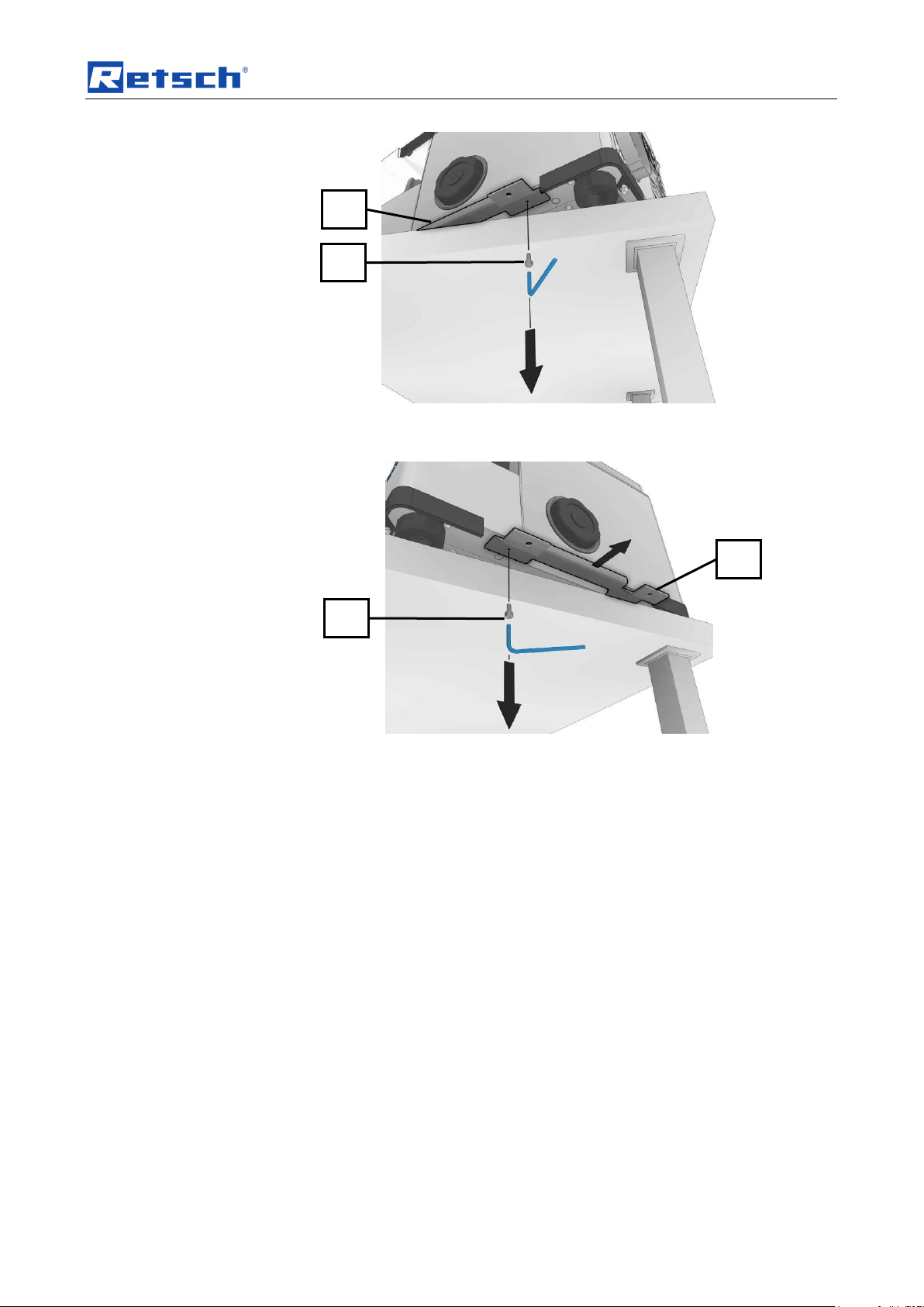
• Place the device on a stable table.
• Pull the device carefully beyond the edge of the table in order to be able to
14
reach the screw (TA).
Page 15
Transport, scope of delivery, installation
TA
TB
TL1
TL1
Fig. 1: Removing the transport bracket
• Remove the screw (TA) using an Allen key.
Fig. 2:
• Pull the device into the position shown in order to be able to remove
the screw (TB).
• Remove the second screw (TB) and remove the transport bracket
(TL1).
NOTICE
Keep the transport brackets, screws and transport lock for future transport!
15
Page 16
Transport, scope of delivery, installation
R
F1 U TL2
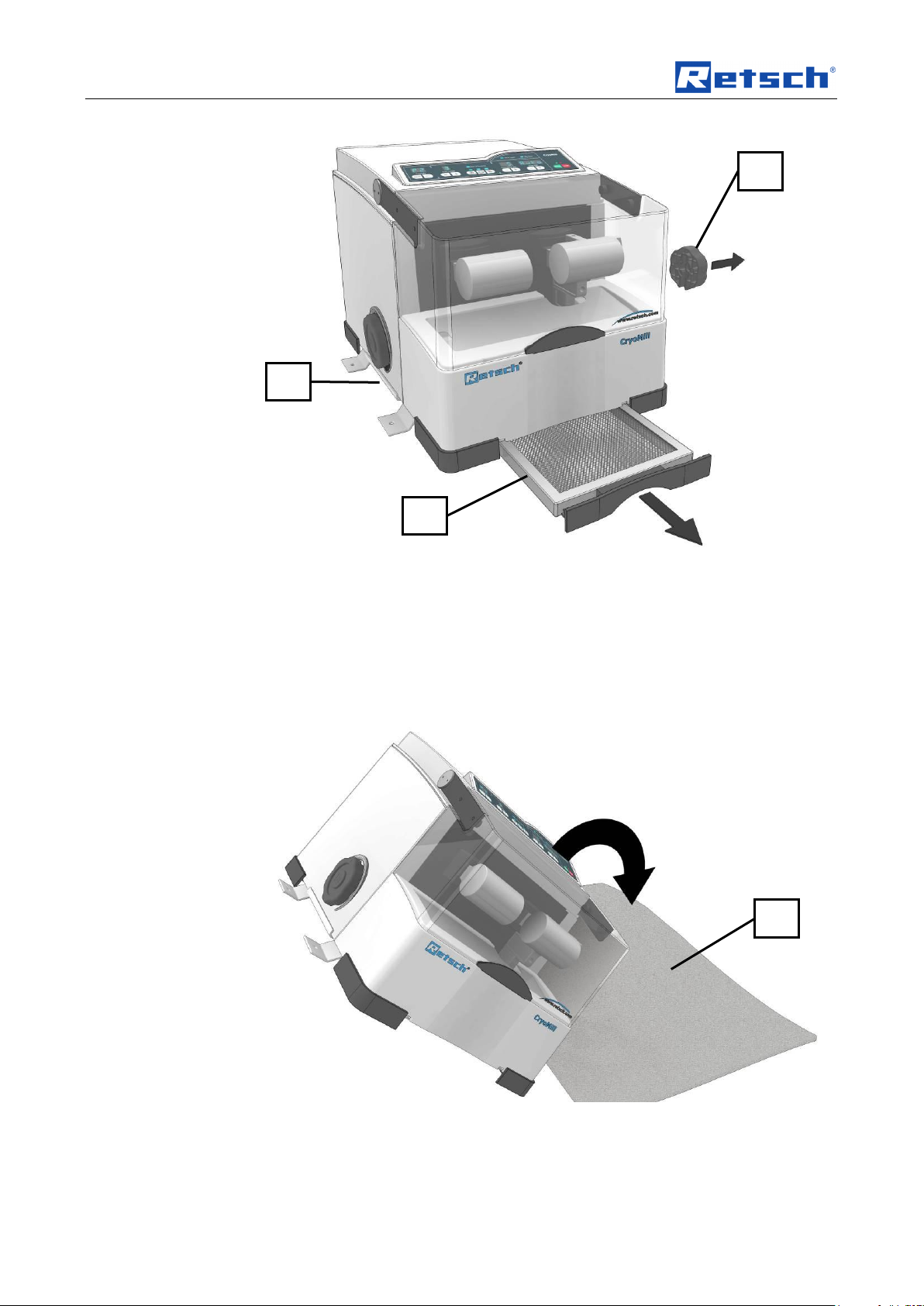
Fig. 3: Pulling out the condensation collecting filter
• Pull the condensation collecting filter (R) completely out of the device.
• Remove the opening aids (F1) on the side on which you have removed the
transport bracket (TL1).
• Place a soft, clean mat (U) next to the device.
• Tilt the device onto the side on which the transport bracket (TL1)
has been removed.
16
Fig. 4: Tilting the device onto its side
Page 17
Transport, scope of delivery, installation
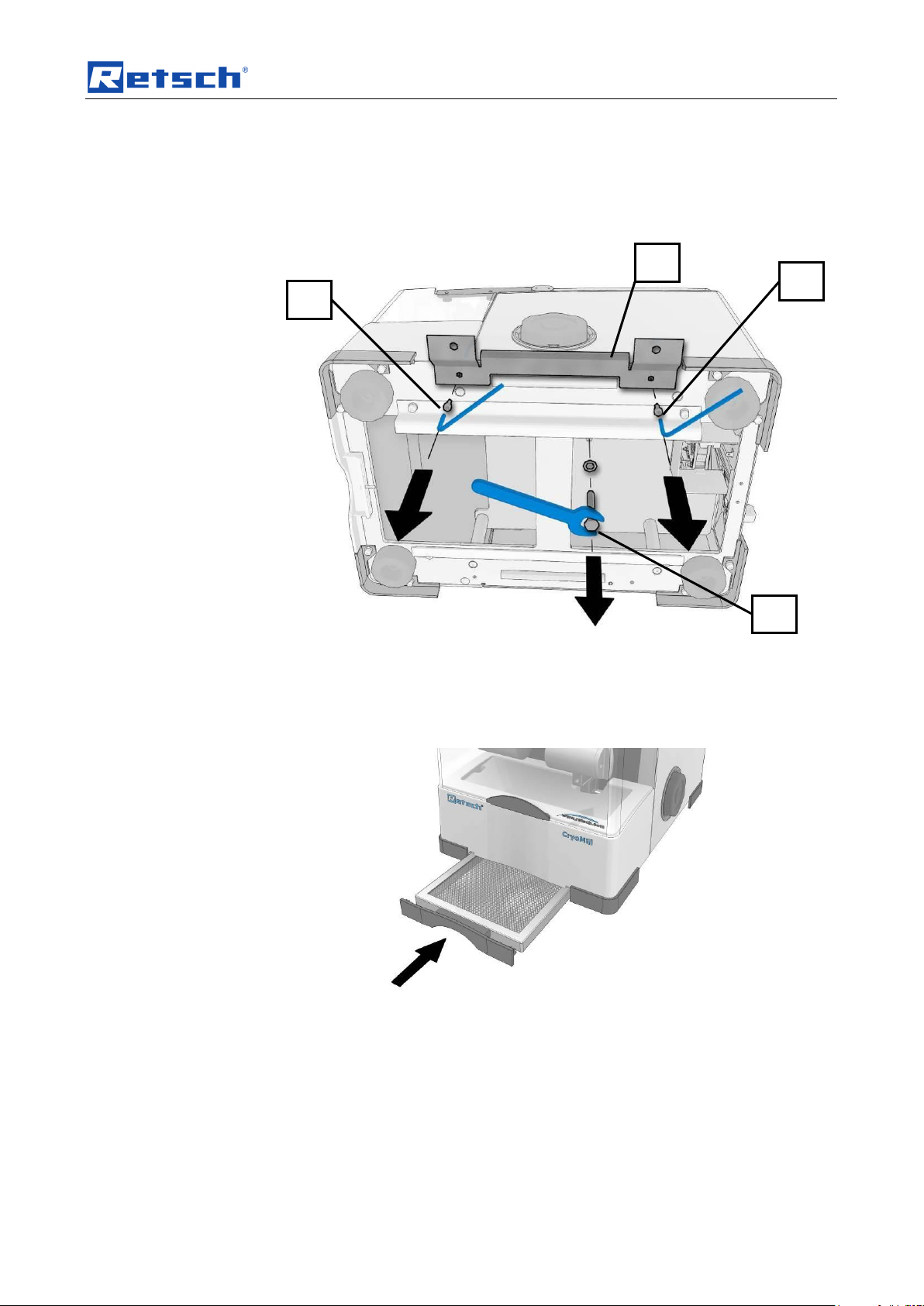
TS
TC
TD
TL2
The transport lock (TS), which is labelled with an arrow, is situated on the
underneath of the device.
Pos: 5.23 /00010 Bedienungsanleitungen K apitelsammlungen/CryoMill II/0006 Tra nsport, Lieferumfang und Aufstellen /0021 Cr yoMill II Modul Griffleiste @ 5\mod_1 355217974441_9.doc @ 36970 @ @ 1
Fig. 5: Removing the transport lock
• Loosen and remove the screw (TS).
• Unscrew the two screws (TC) and (TD).
• Remove the transport bracket (TL2).
Fig. 6:
• Re-insert the condensation collecting filter (R).
NOTICE
Keep the transport brackets, screws and transport lock for future transport!
17
Page 18
Transport, scope of delivery, installation
1 2 3 4 5 6 7 8 9
10
11
12
14
13
GL
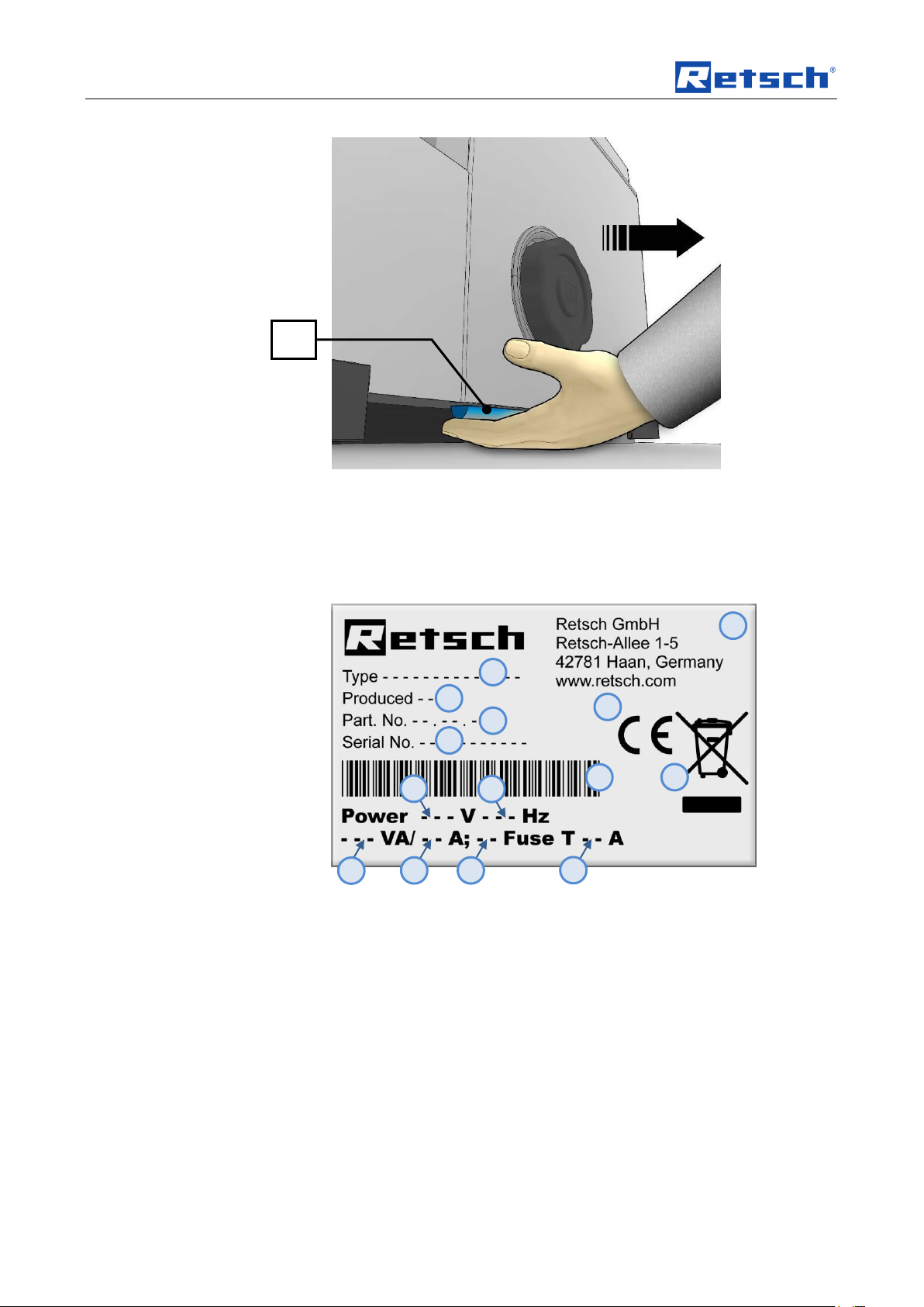
Fig. 7: Grip
A grip (GL) is situated underneath both sides of the device
Pos: 5.24.1 /00005 Überschriften/1.1 Ü berschriften/1.1 Überschriften BDA/11 Type nschild Beschreibung @ 3\mod_128093 3953941_9.doc @ 22302 @ 2 @ 1
• Use the grip (GL) to move the device.
4.7 Type plate description
Pos: 5.24.2 /00003 Standard Kapitel/Gen eral Modul Typenschild @ 3\mod_1280 931092443_9.doc @ 22278 @ @ 1
Fig. 8: Type plate lettering
1 Device designation
2 Year of production
3 Part number
4 Serial number
5 Manufacturer’s address
6 CE marking
7 Disposal label
8 Bar code
9 Power version
10 Mains frequency
18
Page 19
Transport, scope of delivery, installation
WARNING
WARNING
Risk of a fatal electric shock
- An electric shock can cause injuries in the form of burns and cardiac
arrhythmia, respiratory arrest or cardiac arrest.
• Do not clean the blender under running water. Use only a cloth dampened
with water.
• Disconnect the power supply plug before cleaning the blender.
NOTICE
Electrical connection
– Mechanical or electronic components may be damaged.
• Please observe the information on the type plate.
11 Capacity
12 Amperage
13 Number of fuses
14 Fuse type and fuse strength
In the case of questions please provide the device designation (1) or the part
Pos: 5.25 /00005 Überschriften/1.1 Übersc hriften/1.1 Überschriften BDA/11 Elektrisc her Anschluss @ 0\mod_122656506 7445_9.doc @ 3500 @ 2 @ 1
number (3) and the serial number (4) of the device.
4.8 Electrical connection
Pos: 5.26 /00003 Standard Kapitel/Gen eral Modul Elektrischer Anschluss @ 0\ mod_1228918538521_9.doc @ 4731 @ @ 1
When connecting the power cable to the mains supply, use an external fusethat
complies with the regulations applicable to the place of installation .
• Please check the type plate for details on the necessary voltage and
frequency for the device.
• Make sure the levels agree with the existing mains power supply.
• Use the supplied connection cable to connect the device to the mains power
Pos: 5.27 /00010 Bedienungsanleitungen K apitelsammlungen/CryoMill II/0006 Tra nsport, Lieferumfang und Aufstellen /CryoMil l II Modul externe Absicherung @ 5\mod_1343829054956_9.doc @ 33059 @ @ 1
Pos: 5.28 /00004 Warnhinweise/W0002 WARNUNG Kabelbruch Stromstoß @ 2\mod_1278055276120_9.doc @ 20557 @ @ 1
supply.
The external fuse must be at least T6.3A (230V) T8A (100/120V).
Pos: 5.29 /00004 Warnhinweise/H0008 HIN WEIS Elektrischer Anschluss @ 0\ mod_1228918882424_9.doc @ 4781 @ @ 1
Pos: 5.30 /00005 Überschriften/1.1 Ü berschriften/1.1 Überschriften BDA/11 Kü hlmittelzufluss anschließen @ 0\mod_122690 8410419_9.doc @ 3576 @ @ 1
4.9 Connecting the cooling agent feed
Pos: 5.31 /00004 Warnhinweise/H0062 HIN WEIS Risiko der Eisbildung (CryoMill) @ 4\mod_1314082100670_9.doc @ 25 455 @ @ 1
19
Page 20

Transport, scope of delivery, installation
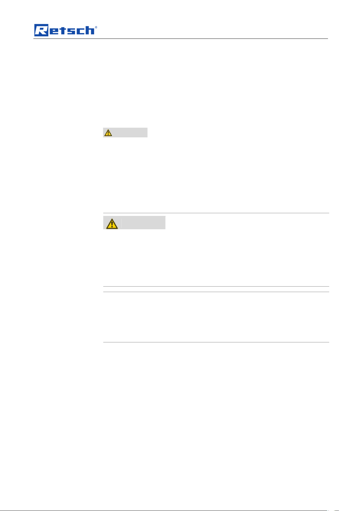
CAUTION
Blocked pipe
Ice formation
– Ice or impurities can block pipes and thereby cause malfunctions.
• Keep the cooling system and supply pipe dry and free from
impurities.
• Do not insert the grinding jar if it is damp or covered with frost.
• Insert the cooling jacket seal (KA) if you will not be using the device
for a long period.
• Do not operate the device unattended.
Pos: 5.32 /00010 Bedienungsanleitungen K apitelsammlungen/CryoMill II/0006 Tra nsport, Lieferumfang und Aufstellen /002 0 CryoMill II Modul Kühlmantel Abdichtung @ 5\mod_1344926871592_9.doc @ 34 120 @ @ 1
20
Page 21
Transport, scope of delivery, installation
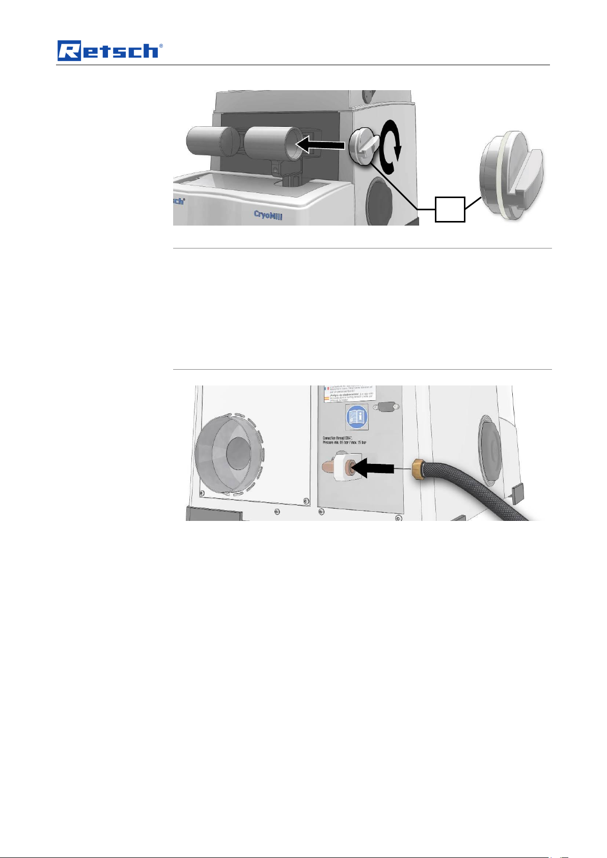
NOTICE
Damage to the machine
Incorrect cooling agent
– The use of cooling agents other than liquid nitrogen will cause the cooling
system to lose its leak tightness.
• Only liquid nitrogen (LN2) may be used as cooling agent with this
device.
KA
Pos: 5.33 /00010 Bedienungsanleitungen K apitelsammlungen/CryoMill II/0006 Tr ansport, Lieferumfang und Aufstellen /001 8 CryoMill II Modul Schematische Darstell ung des Kühlsystems @ 5\mod_134451 1088330_9.doc @ 33941 @ @ 1
Fig. 9: Cooling jacket seal
Fig. 10: Connecting the cooling agent supply
21
Page 22

Transport, scope of delivery, installation
CAUTION
The maximum pressure in the external liquid
nitrogen supply line may be a maximum of 1.5
bar.
The use of a safety valve (SV)
is absolutely essential!
B1 (MV)
B2 (TSM)
TSD
TSM
MV
SV
Pos: 5.34 /00010 Bedienungsanleitung en Kapitelsammlungen/CryoMill II/0006 Tr ansport, Lieferumfang und Aufstellen /00 13 CryoMill II Modul Kühlsystem @ 5\ mod_1344511110312_9.doc @ 33952 @ @ 1
Fig. 11: Diagram of the cooling system
Fig. 12: LED displays
The temperature sensor (TSD) in the LN2 outlet controls the solenoid valve (MV).
The LED (B1) lights up when the solenoid valve (MV) is open.
The temperature sensor (TSM), which is downstream of the solenoid valve,
registers whether liquid nitrogen is flowing into the CryoMill. The LED (B2) lights
up when liquid nitrogen flows into the cooling system.
The device must not be moved in a cryogenic state and no additional forces may
act on the cooling agent connection (N). The cooling agent inlet hose must not be
moved while the device is in a cryogenic state.
22
Page 23

Transport, scope of delivery, installation
CAUTION
Risk of injury and danger of frostbite
Bursting of the inlet hose.
– Depending on the operating state of the device, liquid nitrogen may be
enclosed in the supply line. When heated this may lead to the inlet hose
bursting.
• The maximum pressure in the external liquid nitrogen supply line
may be a maximum of 1.5 bar. The use of a safety valve is absolutely
essential!
CAUTION
Risk of injury and danger of frostbite
Uncontrolled escape of liquid nitrogen
– There is a risk of injury in the event of an uncontrolled escape of liquid
nitrogen.
• Stop the liquid nitrogen supply line immediately!
CAUTION
The connection for the liquid nitrogen (LN2) is a G 1/4 inch threaded connector .
The operating pressure in the liquid nitrogen supply line should be at least 0.5 bar.
The lower the pressure of the liquid nitrogen supply line, the longer the precooling
takes. At 0.5 bar supply line pressure and with the system at room temperature,
precooling requires approx. 10 minutes. Depending on the application, you can
execute up to 4 grinding operations with 10 litres of liquid nitrogen.
Throughout the entire duration of cooling, the air humidity in the chamber
condenses on all cooled parts as a layer of ice .
Pos: 5.35 /00004 Warnhinweise/V0070 VOR SICHT LN2 Austritt (CryoMill) @ 4\ mod_1314082103623_9.doc @ 25491 @ @ 1
Pos: 5.36 /00004 Warnhinweise/H0063 HIN WEIS Wasser aus dem Auffangfilter tro pfen (CryoMill) @ 4\mod_13140821013 89_9.doc @ 25464 @ @ 1
After cooling this condensation drips into the collecting filter and evaporates.
NOTICE
Depending on the ambient temperature, air humidity and duration of use, small
Pos: 5.37 /00005 Überschriften/1.1 Übersc hriften/1.1 Überschriften BDA/11 Kühlmittelz ufluss entfernen @ 1\mod_1238053 128286_9.doc @ 7970 @ @ 1
quantities of water may drip from the collecting filter.
4.10 Removing the liquid nitrogen feed line
Pos: 5.38 /00010 Bedienungsanleitungen K apitelsammlungen/CryoMill II/0006 Tra nsport, Lieferumfang und Aufstellen /001 2 CryoMill II Modul Kühlmittelzufluss entf ernen @ 5\mod_1344511338025_9.doc @ 33963 @ @ 1
Abb. 13: Removing the liquid nitrogen feed line
Before you remove the liquid nitrogen feed line, the pressure must be relieved for
safety reasons.
23
Page 24

Transport, scope of delivery, installation
CAUTION
Risk of injury to eyes and skin
Outlet for gaseous nitrogen
– Liquid nitrogen has a temperature of –196 °C and can cause burn-like
injuries or frostbite in the case of contact with the skin or eyes.
• Do not keep any parts of the body in front of the outlet for gaseous
nitrogen (B).
B
B10
B13
Abb. 14: pressure relief
• Press the (B10) pre-cooling and (B13) START keys simultaneously for 2
seconds.
Pos: 5.39 /00005 Überschriften/1.1 Übersc hriften/1.1 Überschriften BDA/11 Kaltluft- Austritt @ 0\mod_1232374121848_9.d oc @ 5510 @ @ 1
4.11 Cold air outlet
Pos: 5.40 /00010 Bedienungsanleitungen K apitelsammlungen/CryoMill II/0006 Tra nsport, Lieferumfang und Aufstellen /0010 Cr yoMill II Modul Kaltluftaustritt VORSICHT @ 5\mod_1344511373029_9.doc @ 33974 @ @ 1
As long as you keep the keys depressed, the solenoid valve will remain open.
Fig. 15: Outlet for gaseous nitrogen (B)
Pos: 5.41 /00005 Überschriften/1.1 Übersc hriften/1.1 Überschriften BDA/11 Abluftsc hlauch montieren @ 5\mod_134452 2887327_9.doc @ 34030 @ 2 @ 1
4.12 Mounting the exhaust hose
Pos: 5.42 /00010 Bedienungsanleitungen K apitelsammlungen/CryoMill II/0006 Tra nsport, Lieferumfang und Aufstellen /0005 Cr yoMill II Modul Abluftschlauch @ 5\ mod_1344519211701_9.doc @ 34020 @ @ 1
24
Page 25

Transport, scope of delivery, installation
B
BS
BR
Fig. 16: Exhaust hose
Pos: 6.1 /00010 Bedienungsanleitungen Kapitelsammlungen/------- Seitenumbruch ----------- @ 0\mod_1222344373758_ 0.doc @ 2386 @ @ 1
• Fasten the exhaust hose (BR) with the clamp (BS) to the outlet (B).
– The exhaust hose can be extended up to 1 m
25
Page 26

Operating the machine
NOTICE
Area of use of the machine
– This machine is a laboratory machine designed for 8-hour single-shift
operation.
• This machine may not be used as a production machine nor is it
intended for continuous operation.
Pos: 6.2 /00005 Überschriften/1. Überschri ften/1 Bedienung des Gerätes @ 0\m od_1226565880211_9.doc @ 3519 @ 1 @ 1
5 Operating the machine
Pos: 6.3 /00005 Überschriften/1.1 Überschrif ten/1.1 Überschriften BDA/11 Einsatz d er Maschine bei bestimmungsgemäßer V erwendung @ 0\mod_122647673224 8_9.doc @ 3243 @ 2 @ 1
5.1 Use of the machine for the intended purpose
Pos: 6.4 /00010 Bedienungsanleitungen Kapitelsammlungen/CryoMill II/0007 Bedie nung/0023 CryoMill II Modul Zielgruppe Ma schinentyp @ 5\mod_13438292597 04_9.doc @ 33389 @ @ 1
Target group: operating company, operator
Pos: 6.5 /00010 Bedienungsanleitungen Kapitelsammlungen/CryoMill II/0007 Bedie nung/0007 CryoMill II Modul Einsatz bei besti mmungsgemäße Verwendung Cr yoMill @ 5\mod_1343829239142_9.doc @ 33213 @ @ 1
Name of machine model: CryoMill
This machine is a laboratory device and is suitable for the particularly gentle
grinding and homogenisation of heat-sensitive, soft, fibrous, hard and brittle
materials in a dry and wet state.
The CryoMill is designed exclusively for special grinding jars with screw-top lids (no
standard grinding jars) with steel jacket. It is used for the fast pulverization of up to
six samples simultaneously (dpending on the type of grinding jar).
Available grinding jar volumes :
– 50ml;
– 35ml;
– 25ml;
– 10ml;
– 4 x 5ml including adapter; and
Pos: 6.6 /00004 Warnhinweise/H0007 H INWEIS Einsatzbereich des Gerätes 8 Stün diger @ 1\mod_1236240219096_9.doc @ 7693 @ @ 1
Pos: 6.7 /00010 Bedienungsanleitungen Kapitelsammlungen/------- Seitenumbruch ----------- @ 0\mod_1222344373758_ 0.doc @ 2386 @ @ 1
– 6 x 2ml Eppendorf vials.
The closed grinding system guarantees complete recovery of the samples . Due to
the extremely short grinding time and the high final fineness of the grinding sample,
the CryoMill is also ideally suitable for sample preparation for all spectral analyses.
Final fineness levels of up to 5 µm can be achieved depending on the grinding time
and the specific properties of the sample material.
The optimal grinding jar filling is generally 1/3 of the grinding jar volume.
Voluminous materials such as wool, leaves, grasses and similar are exceptions to
this. A fill level of 70 - 80% is necessary here.
26
Page 27

Operating the machine
C
F E F A T D FA
R
H
K,L,M
I O U
N P B J S
B
Pos: 6.8 /00005 Überschriften/1.1 Überschrif ten/1.1 Überschriften BDA/11 Grafisch e Ansichten der Bedienelemente und der Anzeige @ 0\mod_1226566362336_9. doc @ 3537 @ @ 1
5.2 Operating elements and displays
Pos: 6.9 /00010 Bedienungsanleitungen Kapitelsammlungen/CryoMill II/0007 Bedie nung/0003 CryoMill II Modul Bedienelemente und Bedienung Gafische Ansichte n @ 5\mod_1343829232365_9.doc @ 33 169 @ 2 @ 1
Fig. 17: Front view
27
Page 28

Operating the machine
Element
Description
Function
A
Display and control unit:
See below for explanations
Time preselection, frequency preselection and
starting/stopping the machine
B
Nitrogen gas outlet
Outlet for gaseous nitrogen
C
Counterweight left
Counterweight for the cooling jacket with grinding
jar
D
Cooling jacket
Forms the cooling system together with the
grinding jar (T)
E
Hood
Closes the grinding chamber
F
Opening aid
Can be mounted on the grinding jar cover for
simple removal of the grinding jar
FA
Support for opening aid
Storage of the opening aid
H
Fan
Ventilates the motor and the interior of the mill
I
Caution remove mains plug sign
Safety instruction
J
Type plate
Information about the device and connected loads
K
ON / OFF switch
Switches the device on and off
L
Fuse drawer
Accommodates two glass fuses
M
Connector
Connector for the mains lead of the device
N
Cooling agent connection
Connection for liquid nitrogen
O
RS232 interface
Enables updating of the operating software
P
Observe operating instructions sign
Safety instruction
R
Condensation collecting filter
Collects the condensation from the cooling system
and allows it to evaporate
S
Drip tray
Housing protection
T
Grinding jar
Forms the cooling system together with the cooling
jacket (D)
Fig. 18: Rear view
5.3 Summary table of device parts
Pos: 6.10 /00010 Bedienungsanleitungen K apitelsammlungen/------- Seitenumbruch ----------- @ 0\mod_1222344373758 _0.doc @ 2386 @ @ 1
28
Page 29

Operating the machine
Element
Description
Function
B1
LED on – valve open
LED off – valve closed
Indicates whether the internal solenoid valve on the
liquid nitrogen supply line is open or closed.
B2
LED on – liquid nitrogen is flowing
LED off – no liquid nitrogen
Indicates that liquid nitrogen is flowing into the device.
B3
LED precooling is running (Vkz)
Precooling is taking place / lights up when values are
set
B4
LED grinding is running (Mz)
The sample is ground / lights up when values are set
B5
LED intermediate cooling is running
(Zkz)
Intermediate cooling is taking plate / lights up when
values are set
B7
Frequency minus button
In setting mode and in operating mode:
reduces the set frequency by 1 Hz (1/s). Continuous
pressing switches on fast scrolling of numbers.
Frequency plus button
In setting mode and in operating mode:
increases the set frequency by 1 Hz (1/s). Continuous
pressing switches on fast scrolling of numbers.
B8
Cooling cycle minus button
Reduces the number of total cycles by 1
Cooling cycle plus button
Increases the number of total cycles by 1
B9
Time minus button
In setting mode and in operating mode:
Reducing the set
• Precooling
• Grinding time
• Intermediate cooling time
B10
B7
B8
B15
B2
B1
B11
B12
B13
B9
B14
B3
B4
B5
Pos: 6.11 /00005 Überschriften/1.1 Übersc hriften/1.1 Überschriften BDA/11 Bedie nelemente und Anzeigen @ 0\mod_122 6566557086_9.doc @ 3543 @ @ 1
5.4 Operating elements and displays
Pos: 6.12 /00010 Bedienungsanleitungen K apitelsammlungen/CryoMill II/0007 Bedi enung/0002 CryoMill II Modul Anzeige und Bedieneinheit @ 5\mod_1343829230 960_9.doc @ 33158 @ @ 1
Fig. 19: Control unit
29
Page 30

Operating the machine
Time plus button
In setting mode and in operating mode:
Increasing the set
• Precooling
• Grinding time
• Intermediate cooling time
B10
Setting precooling
Preselection button to set the precooling / switching
automatic precooling on or off)
B11
Setting grinding
Preselection button to set the grinding time
B12
Setting intermediate cooling
Preselection button to set the intermediate cooling time
B13
Start button
Green LED
Starts grinding operation
Indicates grinding operation
Stop button
Red LED and ON
Interrupts or ends grinding operation,
places the machine in stand-by mode
B14
LED - auto precooling
Indicates whether the automatic precooling is switched
on
B15
PROG button
Button to select a program
SET button
Button starts / saves a program editing
Pos: 6.13 /00010 Bedienungsanleitungen K apitelsammlungen/------- Seitenumbruch ----------- @ 0\mod_1222344373758 _0.doc @ 2386 @ @ 1
30
Page 31

Operating the machine
CAUTION
Danger of injury and frostbite
Escape of liquid nitrogen
– Liquid nitrogen has a temperature of –196 °C and may cause injuries
similar to burns on skin or eye contact or frostbite.
• Never switch the machine on without tightly closed cooling casing.
CAUTION
Crushed or bruised fingers
Falling grinding chamber protective hood
– The protective hood of the grinding chamber can cause crushed or bruised
fingers if it falls down.
• Hold the flap tight when closing.
CAUTION
Clogged piping
Formation of ice
– Ice or foreign matter can clog the pipe and subsequently cause
malfunctioning.
• Do not insert the grinding jar if it is damp or covered with frost.
• Use the cooling jacket sealing plug (KA) if you are not going to use
the device for a long time.
• Do not let the device run without supervision.
Pos: 6.14 /00005 Überschriften/1.1 Übersc hriften/1.1 Überschriften BDA/11 Mahlbe hälter einsetzen @ 0\mod_1226569844 414_9.doc @ 3555 @ @ 1
5.5 Inserting the grinding jar
Pos: 6.15 /00010 Bedienungsanleitungen K apitelsammlungen/CryoMill/0101 Warnhin weise/CryoMill VORSICHT Austritt von fl üssigem Stickstoff @ 0\mod_12287496 57712_9.doc @ 4360 @ @ 1
Pos: 6.16 /00004 Warnhinweise/V0008 VOR SICHT Klappe beim Schließen festhalte n (CryoMill) @ 2\mod_127805421350 5_9.doc @ 20549 @ @ 1
Pos: 6.17 /00005 Überschriften/1.1.1 Ü berschriften/111 CryoMill Spezial Mahlbecher einsetzen @ 0\mod_122751681255 5_9.doc @ 3966 @ @ 1
5.5.1 Inserting and removing CryoMill special grinding jar
Pos: 6.18 /00010 Bedienungsanleitungen K apitelsammlungen/CryoMill/0101 Warn hinweise/CryoMill HINWEIS Risiko der Eis bildung @ 0\mod_1234165670129_9. doc @ 6140 @ @ 1
Pos: 6.19 /00010 Bedienungsanleitungen K apitelsammlungen/CryoMill II/0007 Bedi enung/0014 CryoMill II Modul Mahlbecher Ei nsetzen wechseln @ 5\mod_13438 29248165_9.doc @ 33290 @ @ 1
31
Page 32

Operating the machine
KM
SM
1.
2.
Fig. 20: Dismantling the grinding jar retaining device
• Unscrew the lock nut (KM).
• Remove the screw (SM).
Fig. 21: Inserting the grinding jar
• Insert the special grinding jar filled with the grinding material and grinding
balls into the cooling jacket .
• Twist the grinding jar in completely.
32
Page 33

Operating the machine
CAUTION
Risk of injury to eyes and skin
The cooling jacket and grinding jar reach very low temperatures
during grinding.
– Risk of injury to eyes and skin from severe frostbite
• As a matter of principle, always wear goggles and
protective gloves when opening the cooling jacket and the
grinding jar.
KM
2.
1.
SM
Fig. 22: Securing the grinding jar
• First tighten the screw (SM) by hand (hand-tight).
• Then tighten the lock nut against the cooling jacket. Use the locking pin
provided to do this.
Ensure that the grinding jar is tightly screwed to the cooling jacket, otherwise liquid
nitrogen can escape.
The lock screw (SM) must be screwed tight and secured with the lock nut so that
no sample material escapes from the grinding jar.
Use the opening aid (F) that is kept on the side of the device to remove the
grinding jar .
• Unscrew the lock nut (KM)
• Remove the screw (SM)
• Mount the opening aid (F) on the grinding jar and open it.
33
Page 34

Operating the machine
NOTE
1.H0017
Damage to the PTFE grinding jar
– The threading on the grinding jar can become damaged.
• When it is being inserted into the device, the PTFE grinding jar must
be at room temperature and must not be pre-cooled.
NOTICE
Blocked pipe
Ice formation
– Ice or impurities can block pipes and thereby cause malfunctions.
• Insert the cooling jacket seal (KA) as soon as you are no longer using
the device.
F
Pos: 6.20 /00004 Warnhinweise/H0056 HIN WEIS Cryomill PTFE Mahlbecher nur mit Zimmertemperatur einsetzen - Nicht vorkühlen @ 4\mod_1314082879240_9.d oc @ 25509 @ @ 1
Pos: 6.21 /00005 Überschriften/1.1.1 Ü berschriften/111 Kühlmantel Abdichtung eins etzten @ 2\mod_1266314975785_9.doc @ 18787 @ @ 1
Fig. 23: Using the opening aid
5.5.2 Inserting the cooling jacket sealing plug
Pos: 6.22 /00010 Bedienungsanleitungen K apitelsammlungen/CryoMill II/0007 Bedi enung/0011 CryoMill II Modul Kühlmantela bdichtung einsetzen @ 5\mod_134 3829244950_9.doc @ 33257 @ @ 1
34
Page 35

Operating the machine
KA
Pos: 6.23 /00005 Überschriften/1.1.1 Ü berschriften/111 Adapter für 4/2 x 5ml Ma hlbecher einsetzen @ 0\mod_1227516748 177_9.doc @ 3960 @ @ 1
Fig. 24: Inserting the cooling jacket seal
5.5.3 Insert the adapter for 4/2 x 5 ml grinding jar
Pos: 6.24 /00010 Bedienungsanleitungen K apitelsammlungen/CryoMill II/0007 Bedi enung/0001 CryoMill II Modul 5ml Mahlbec her einsetzen @ 5\mod_13438292 29211_9.doc @ 33147 @ @ 1
You can operate the CryoMill with 4 or 2 (5 ml) grinding jars.
• Insert the 5 ml grinding jars into the adapter as shown in the following
diagram.
Fig. 25: Inserting a 5ml grinding jar
Note the positioning of the grinding jars. If you are using two grinding jars, these
must be inserted in opposite openings.
Fig. 26: 5ml grinding jar position
35
Page 36

Operating the machine
NOTICE
Breaking of Eppendorf reaction vials
Changing material properties
– The Eppendorf reaction vials that are available as accessories change
their material properties during the cryogen grinding.
• Do not reuse reaction vials after the cryogen grinding.
• Do not insert reaction vials in centrifuges after the cryogen grinding
• Grinding may take place with a maximum 25Hz.
Pos: 6.25 /00005 Überschriften/1.1.1 Ü berschriften/111 Adapter für 4/2 x 2 ml Epp endorf Reaktionsgefäße einsetzen @ 1\ mod_1243499921893_9.doc @ 10328 @ @ 1
Fig. 27: Inserting the grinding jar adapter
5.5.4 Insert the adapter for 6 / 4 / 2 x 2-ml Eppendorf reaction vial
Pos: 6.26 /00010 Bedienungsanleitungen K apitelsammlungen/CryoMill/0101 Warnhin weise/CryoMill HINWEIS Zerbrechen von Eppendorf Reaktionsgefäßen @ 1\m od_1243499975784_9.doc @ 10336 @ @ 1
Pos: 6.27 /00010 Bedienungsanleitungen K apitelsammlungen/CryoMill II/0007 Bedi enung/0008 CryoMill II Modul Eppendorf G efäße einsetzen @ 5\mod_134382 9240370_9.doc @ 33224 @ @ 1
You can operate the CryoMill with 2, 4 or 6 Eppendorf reaction vials (2ml).
NOTICE
Grinding with Eppendorf reaction vials may only take place with a maximum 25Hz.
(frequency 1/s)
• Insert the 2ml Eppendorf reaction vials into the adapter for reaction vials as
shown in the diagram below.
Fig. 28: Inserting 2ml Eppendorf reaction vials
36
Page 37

Operating the machine
Note the positioning of the Eppendorf reaction vials. If you are using two or four
reaction vials, these must be inserted in opposite openings.
Pos: 6.28 /00005 Überschriften/1.1 Übersc hriften/1.1 Überschriften BDA/11 Erläuter ungen zu den Mahlzyklen @ 0\mod_1 227686930552_9.doc @ 4010 @ @ 1
Fig. 29: Position of 2 ml reaction vials
5.6 Explanations of the grinding cycles
Pos: 6.29 /00010 Bedienungsanleitungen K apitelsammlungen/CryoMill II/0007 Bedi enung/0009 CryoMill II Modul Erläuterungen zu den Mahlzyklen @ 5\mod_13438 29242206_9.doc @ 33235 @ 33 @ 1
You can deploy the CryoMill for grinding with cooling or grinding without cooling.
5.6.1 Grinding without cooling
• Switch the CryoMill on at the main switch.
• Set the cryo cycles to - .
• Set the desired grinding time (B9)+(B11).
• Press the START button.
The START LED lights up. The remaining grinding time and the set frequency are
displayed.
5.6.2 Grinding with cooling
The following program points can be set when grinding with cooling.
– precooling (Vkz)
– grinding time (Mz)
– intermediate cooling time (Zkz)
– cryo cycles (Number of cooling/grinding cycles)
– frequency 1/s (Grinding frequency)
A single grinding cycle consists of the precooling and the set grinding time. The
intermediate cooling time does not apply in the case of a single grinding cycle.
37
Page 38

Operating the machine
B15
Vkz + Mz = total grinding time
Fig. 30: Sequence of a single grinding cycle
Multiple grinding cycles consist of the precooling, the set grinding time and the
intermediate cooling time.
Number of cryo cycles: n
Vkz + (n-1) (Mz + Zkz) + Mz = total grinding time
Precooling + [(number of set cryo cycles) - 1] x (grinding time + intermediate cooling time) +
grinding time = total grinding time
Pos: 6.30 /00005 Überschriften/1.1 Übersc hriften/1.1 Überschriften BDA/11 Prog ramme @ 5\mod_1344511635554_9.doc @ 33985 @ 2 @ 1
Fig. 31: Sequence of two grinding cycles
5.7 Programs
Pos: 6.31 /00005 Überschriften/1.1.1 Ü berschriften/111 Vermahlung ohne Program m @ 5\mod_1344590601015_9.doc @ 34040 @ 3 @ 1
5.7.1 Grinding without program
Pos: 6.32 /00010 Bedienungsanleitungen K apitelsammlungen/CryoMill II/0007 Bedi enung/0024 CryoMill II Modul Vermahlu ng ohne Programm @ 5\mod_13445117 04525_9.doc @ 33995 @ @ 1
Fig. 32: Grinding without program
• Press the PROG button (B15) until “- -” is shown in the memory display .
38
Page 39

Operating the machine
B15
B7
B8
B9
B10
B11
B12
The display advances one program each time the button is pressed
- - > P1 > P2 > P3 > P4 > P5 > P6 > P7 > P8 > P9
Pos: 6.33 /00005 Überschriften/1.1.1 Ü berschriften/111 Vermahlung mit Program m @ 5\mod_1344590647615_9.doc @ 34 050 @ 3 @ 1
– The SET button (B15) is blocked in the “- -” mode
5.7.2 Grinding with program
Pos: 6.34 /00010 Bedienungsanleitungen K apitelsammlungen/CryoMill II/0007 Bedi enung/0025 CryoMill II Modul Vermahlung mit Programm @ 5\mod_1344512 746227_9.doc @ 34005 @ 4444 @ 1
Fig. 33: Grinding with program
5.7.2.1 Selection of a program
• Press the PROG button (B15) until the required program is shown in the
memory display.
– The display advances one program each time the button is pressed .
- - > P1 > P2 > P3 > P4 > P5 > P6 > P7 > P8 > P9
– The buttons B8, B7, B9 are blocked due to the selection of a program.
5.7.2.2 Display of the program grinding parameters
Precooling
• Press the precooling button (B10).
– The set time for precooling appears in the time min (B9) display.
Grinding time
• Press the grinding time button (B11).
– The set time for the grinding time appears in the time min (B9) display.
Intermediate cooling
• Press the intermediate cooling button (B12).
– The set time for the intermediate cooling appears in the time min (B9)
display.
5.7.2.3 Create/change a program
• Press the PROG button (B15) until the required program (memory space) is
displayed in the memory display.
• Press the SET button (B15).
– All displays and the corresponding LEDs for which settings are possible light
up or flash.
39
Page 40

Operating the machine
B8
• Set the parameters for grinding as described in the following chapters:
- Number of grinding cycles
- Precooling
- Grinding time
- Intermediate cooling time
- Grinding frequency
– It is possible to cancel at any time using the PROG button (B15)
• Press the SET button (B15).
– Pressing the SET BUTTON (B15) again stores all parameters in the
program.
5.7.2.4 Delete program
• Press the PROG button (B15) until the program to be deleted is displayed in
the memory display.
• Press the shortcut SET (B15) and - (B8) for at least 5 seconds.
Fig. 34: Deleting a program
– The program is deleted and the parameters are assigned with the values “0”
or “-”.
Pos: 6.35 /00005 Überschriften/1.1 Übersc hriften/1.1 Überschriften BDA/11 Mahl- Zyklen einstellen @ 0\mod_12271852531 26_9.doc @ 3879 @ @ 1
– It is not possible to start a deleted program.
5.8 Setting grinding cycles
Pos: 6.36 /00010 Bedienungsanleitungen K apitelsammlungen/CryoMill II/0007 Bedi enung/0017 CryoMill II Modul Mahlzyklen ei nstellen @ 5\mod_1343829253169 _9.doc @ 33323 @ @ 1
Fig. 35: Setting the grinding cycles
40
• Switch the CryoMill on at the main switch.
– After switching on, the last used grinding parameters are displayed and can
be used.
– You can set 0 ("-") to 9 grinding cycles
NOTICE
If 0 ("-") CryoCycles are set, the grinding is conducted without nitrogen. In this
case the buttons B10, B11 and B12 are blocked.
Page 41

Operating the machine
B10
B9
ap
– The first cycle consists of the precooling phase and grinding time
– Cycles 2 to 9 each comprise an intermediate cooling and grinding.
• Press the respective buttons (B8) to set the grinding cycles.
• + Pressing briefly increases the number.
• - Pressing briefly reduces the number.
Pos: 6.37 /00005 Überschriften/1.1 Übersc hriften/1.1 Überschriften BDA/11 Vor kühlzeit einstellen @ 0\mod_12271851066 11_9.doc @ 3867 @ @ 1
– The display runs more quickly when pressed longer.
5.9 Setting the precooling time
Pos: 6.38 /00010 Bedienungsanleitungen K apitelsammlungen/CryoMill II/0007 Bedi enung/0022 CryoMill II Modul Vorkühlzeit ein stellen @ 5\mod_134382925856 7_9.doc @ 33378 @ 33 @ 1
NOTICE
The machine runs at a fixed frequency of 5 Hz during the precooling and
intermediate cooling.
A range of from 30 seconds to 99 minutes can be set for precooling.
Fig. 36: Setting precooling
After switching on, the last used grinding parameters are displayed and can be
used.
• Switch the CryoMill on at the main switch.
• Press the button (B10) to set precooling
– The precooling LED lights up.
You can choose between two precooling versions:
5.9.1 Precooling with definable precooling time
• Use the buttons (B9) to set precooling.
• + Pressing briefly increases the duration.
• - Pressing briefly shortens the duration.
The display runs more quickly when pressed longer.
5.9.2 Automatic precooling
In the case of automatic precooling the grinding only starts once the entire system
has been sufficiently cooled. This is checked by a sensor (see chapter
>>Connecting the cooling agent supply <<)
Switch automatic precooling on
• Press the button (B10) for at least 2 seconds.
41
Page 42

Operating the machine
B12
B9
LED
B11
B9
LED
– The auto precooling (ap) LED is lit up.
– “Auto” is shown in the time min display.
Switch automatic precooling off
• Press the button (B10) for at least 2 seconds.
– The auto precooling (ap) LED is extinguished.
Pos: 6.39 /00005 Überschriften/1.1 Übersc hriften/1.1 Überschriften BDA/11 Mahlda uer einstellen @ 0\mod_122690845696 5_9.doc @ 3582 @ @ 1
– “08:00" is shown in the time min display.
5.10 Setting the grinding time
Pos: 6.40 /00010 Bedienungsanleitungen K apitelsammlungen/CryoMill II/0007 B edienung/0015 CryoMill II Modul Mahldauer einstellen @ 5\mod_1343829251134_9. doc @ 33301 @ @ 1
Fig. 37: Setting the grinding time
• Press the button (B11) to set the grinding time.
The grinding time LED lights up.
• Use the buttons (B9) to set the grinding time
(5 to 30 Hz in 1Hz steps).
– + Pressing briefly increases the duration.
– - Pressing briefly shortens the duration.
The display runs more quickly when pressed longer.
NOTICE
In the case of grinding without cooling, the grinding time can be set directly using
Pos: 6.41 /00005 Überschriften/1.1 Übersc hriften/1.1 Überschriften BDA/11 Dauer d er Zwischenkühlung einstellen @ 0\ mod_1227185184595_9.doc @ 3873 @ @ 1
5.11 Setting the duration of intermediate cooling
Pos: 6.42 /00010 Bedienungsanleitungen K apitelsammlungen/CryoMill II/0007 Bedi enung/0006 CryoMill II Modul Dauer der Z wischenkühlung einstellen @ 5\mod_13 43829237941_9.doc @ 33202 @ @ 1
42
the buttons (B9).
Fig. 38: Setting the intermediate cooling
Page 43

Operating the machine
CAUTION
Danger of injury and frostbite
Escape of liquid nitrogen
– Liquid nitrogen has a temperature of –196 °C and may cause injuries
similar to burns on skin or eye contact or frostbite.
• Never switch the machine on without tightly closed cooling casing.
B7
• Press the button (B12) to set the intermediate cooling .
The intermediate cooling time LED lights up.
• Use the buttons (B9) to set the intermediate cooling time
(30 seconds to 99:00 minutes).
– + Pressing briefly increases the duration.
– - Pressing briefly shortens the duration.
Pos: 6.43 /00005 Überschriften/1.1 Übersc hriften/1.1 Überschriften BDA/11 Mahlfreq uenz einstellen @ 0\mod_122690855 9789_9.doc @ 3588 @ @ 1
The display runs more quickly when pressed longer.
5.12 Setting the grinding frequency
Pos: 6.44 /00010 Bedienungsanleitungen K apitelsammlungen/CryoMill II/0007 Bedi enung/0016 CryoMill II Modul Mahlfrequenz einstellen @ 5\mod_1343829252 220_9.doc @ 33312 @ @ 1
Fig. 39: Frequency 1/s
• Switch the CryoMill on at the main switch.
It is only possible to adjust the grinding frequency if the button (B11) for setting the
grinding parameters has been pressed and the LED (B11) is lit up.
• Press the button (B11).
• Press the respective buttons (B7) to set the grinding frequency .
The selectable frequency range is from 3 to 30 Hz.
• + Pressing briefly increases the frequency.
• - Pressing briefly reduces the frequency.
The display runs more quickly when pressed longer.
The frequency of precooling and intermediate cooling is fixed at 5 Hz. The
frequency cannot be adjusted while setting the precooling or intermediate cooling
Pos: 6.45 /00005 Überschriften/1.1 Übersc hriften/1.1 Überschriften BDA/11 Mahl vorgang starten @ 0\mod_122718500819 0_9.doc @ 3861 @ @ 1
time.
5.13 Starting the grinding process
Pos: 6.46 /00010 Bedienungsanleitungen K apitelsammlungen/CryoMill/0101 Warnhin weise/CryoMill VORSICHT Austritt von fl üssigem Stickstoff @ 0\mod_12287496 57712_9.doc @ 4360 @ @ 1
Pos: 6.47 /00010 Bedienungsanleitungen K apitelsammlungen/CryoMill/0101 Warnhin weise/CryoMill HINWEIS Der Mahlvorga ng kann nur gestartet werden, wenn die Haube geschlossen ist. @ 0\mod_12 28833855525_9.doc @ 4432 @ @ 1
NOTICE
Pos: 6.48 /00010 Bedienungsanleitungen K apitelsammlungen/CryoMill II/0007 Bedi enung/0020 CryoMill II Modul Start des Ma hlvorganges @ 5\mod_134382925 6297_9.doc @ 33356 @ @ 1
The grinding process can only be started if the hood is closed.
43
Page 44

Operating the machine
B13
B13
B13
Fig. 40: Starting the grinding process
• Press the START button to start the grinding process.
– The Start LED (green) lights up. At the same time the solenoid valve opens
Pos: 6.49 /00005 Überschriften/1.1 Ü berschriften/1.1 Überschriften BDA/11 Mahl vorgang unterbrechen und weiterführen @ 1 \mod_1241510629134_9.doc @ 8833 @ @ 1
and liquid nitrogen can flow into the cooling system.
5.14 Interrupting and continuing the grinding process
Pos: 6.50 /00010 Bedienungsanleitungen K apitelsammlungen/CryoMill II/0007 Bedi enung/0026 CryoMill II Modul Pausenfun ktion @ 5\mod_1345098786153_9.doc @ 34130 @ @ 1
5.14.1 Pausing grinding
Fig. 41: Pausing grinding
• Press the STOP button (B13) once.
– Grinding is interrupted and the LED above the START button flashes.
5.14.2 Cancelling grinding
Fig. 42:
• Press the STOP button (B13) twice.
– The grinding is ended and the two LEDs above the START and STOP
Pos: 6.51 /00005 Überschriften/1.1 Übersc hriften/1.1 Überschriften BDA/11 Mahl vorgang stoppen @ 0\mod_1226909892 231_9.doc @ 3643 @ @ 1
buttons are off.
5.15 Stopping the grinding process
Pos: 6.52 /00010 Bedienungsanleitungen K apitelsammlungen/CryoMill II/0007 Bedi enung/0021 CryoMill II Modul Stoppen des Ma hlvorganges @ 5\mod_1343829 257317_9.doc @ 33367 @ @ 1
44
Page 45

Operating the machine
K
Fig. 43: Ending the grinding process
• Press the STOP button to end the grinding process.
The STOP LED (red) lights up. At the same time the solenoid valve closes.
In the event that the supply of liquid nitrogen has been interrupted during
operation, this is indicated by the flashing of the remaining time LED (B6) at the
end of the grinding time.
Pressing once interrupts the grinding process, for example to appraise the grinding
sample. The remaining grinding time is still visible on the display.
By pressing the start button again, the mill continues running until the grinding time
has completely expired.
Pressing the stop button twice aborts the grinding process. The machine is now in
start mode.
By pressing the start button, the display is activated again and the grinding time is
reset to the last start setting.
The duration can be changed during the grinding process. The grinding process is
automatically ended on expiry of the grinding time. The display is reset to the last
Pos: 6.53 /00005 Überschriften/1.1 Übersc hriften/1.1 Überschriften BDA/11 Betriebss tunden-Anzeige @ 0\mod_1226909 921463_9.doc @ 3649 @ @ 1
value started.
5.16 Operating hours display
Pos: 6.54 /00010 Bedienungsanleitungen K apitelsammlungen/CryoMill II/0007 Bedi enung/0005 CryoMill II Modul Betriebsstun den anzeigen @ 5\mod_1343829236 125_9.doc @ 33191 @ @ 1
• Switch the device off at the mains switch.
Fig. 44: Switching the device on and off
• Keep the buttons cryo cycles (B8) + and frequency (B7) - pressed
simultaneously and with the buttons pressed, switch the device on at the
mains switch.
45
Page 46

Operating the machine
K
B7
B8
B7
B8
Fig. 45: Display of the operating hours
The total operating time in hours is displayed. The maximum value that can be
depicted is 999999 hours. The letters bS are displayed in the first two places.
Examples:
bS0 00 012 = 12 hours operating time
bS1 23 456 = 123456 hours operating time
Pos: 6.55 /00005 Überschriften/1.1 Übersc hriften/1.1 Überschriften BDA/11 Betriebss oftware-Anzeige @ 0\mod_1226909 994341_9.doc @ 3655 @ @ 1
• Press the STOP button to exit the operating hours display
5.17 Operating software display
Pos: 6.56 /00010 Bedienungsanleitungen Kapitelsammlungen/CryoMill II/0007 Bedi enung/0004 CryoMill II Modul Betriebssoft ware anzeigen lassen @ 5\mod_134 3829234568_9.doc @ 33180 @ @ 1
• Switch the device off at the mains switch.
Fig. 46: Switching the device on and off
• Keep the buttons cryo cycles (B8) + and frequency (B7) + pressed
simultaneously and...
• ...with the buttons pressed, switch on the device at the mains switch.
Fig. 47: Display of the software version
The current version of the operating software is displayed across the two right-
hand display windows. The letter S is shown in first place.
Examples:
S 1.23 = Version 1.23 of the operating software
S 2.00 = Version 2.00 of the operating software
• Press the STOP button to exit the display of the
Pos: 6.57 /00005 Überschriften/1.1 Übersc hriften/1.1 Überschriften BDA/11 Austa usch der Gerätesicherungen @ 0\mod_ 1228833758657_9.doc @ 4426 @ @ 1
operating software.
5.18 Replacing the machine fuses
Pos: 6.58 /00010 Bedienungsanleitungen K apitelsammlungen/CryoMill II/0007 Bedi enung/0019 CryoMill II Modul Sicheru ng austauschen @ 5\mod_134382925523 8_9.doc @ 33345 @ @ 1
46
Page 47

Operating the machine
L
M
Fig. 48: Replacing the device fuses
The following glass fuses are needed for the CryoMill:
2 T4A
• Pull the mains plug from the connector (M).
• Press in the catch at the side. This releases the fuse holder (L) so that it
can be pulled out.
• Replace the fuses.
Pos: 7.1 /00010 Bedienungsanleitungen Kapitelsammlungen/------- Seitenumbruch ----------- @ 0\mod_1222344373758_ 0.doc @ 2386 @ @ 1
• Push the fuse holder (L) in until it engages.
47
Page 48

Working instructions
CAUTION
2.V0004
Risk of explosion or fire
Changing sample properties
– Consider that the properties and therefore also the hazardousness of your
sample can change during the grinding process.
• Do not use any substances in this device which carry the risk of
explosion or fire.
CAUTION
Danger of personal injury
Dangerous nature of the sample
– Depending on the dangerous nature of your sample, take the
necessary measures to rule out any danger to persons.
• Observe the safety guidelines and datasheets of your
sample material.
Recommended ball filling (unit)
Pos: 7.2 /00005 Überschriften/1. Überschri ften/1 Arbeitsweise @ 0\mod_12269 10058402_9.doc @ 3661 @ @ 1
6 Working instructions
Pos: 7.3 /00005 Überschriften/1.1 Überschrif ten/1.1 Überschriften BDA/11 Allge meines @ 0\mod_1226913421529_9.doc @ 3723 @ @ 1
6.1 General
Pos: 7.4 /00010 Bedienungsanleitungen Kapitelsammlungen/CryoMill II/0008 Arbei tsweise/0001 CryoMill II Modul Allgem eines @ 5\mod_1343830265008_9.doc @ 33411 @ @ 1
The CryoMill is an extremely modern, efficient product from Retsch GmbH.
Due to the large selection of accessories, the CryoMill has a wide range of
potential applications in industrial and research laboratories.
It is primarily deployed in the chemical and pharmaceutical area, in mineralogy and
Pos: 7.5 /00004 Warnhinweise/V0004 VORS ICHT Explosions- oder Brandgefa hr Vermahlen @ 1\mod_1236238455830_9 .doc @ 7626 @ @ 1
Pos: 7.6 /00004 Warnhinweise/V0006 VORS ICHT Gefahr von Personenschäden Ge fährliche Stoffe @ 1\mod_1236238456 269_9.doc @ 7634 @ @ 1
biology etc.
Pos: 7.7 /00005 Überschriften/1.1 Überschrif ten/1.1 Überschriften BDA/11 Der Mahl vorgang @ 0\mod_1226910105487_9.d oc @ 3667 @ @ 1
6.2 The grinding process
Pos: 7.8 /00010 Bedienungsanleitungen Kapitelsammlungen/CryoMill II/0008 Arbei tsweise/0004 CryoMill II Modul Mahlvorgang @ 5\mod_1343830267351_9.doc @ 33444 @ @ 1
• Insert your grinding jar filled with grinding sample and grinding ball/s into the
grinding jar support as described in the chapter "Inserting the grinding jar”.
• Close the hood.
• Set the grinding parameters.
• Open your external liquid nitrogen supply line.
• Start the device.
Do not open the hood during the grinding process.
The grinding jars are brought to a halt immediately by the built-in brake, however
the grinding process can no longer be continued with the remaining grinding time.
Pos: 7.9 /00005 Überschriften/1.1 Überschrif ten/1.1 Überschriften BDA/11 Mahlgu tmengen und Aufgabe-Korngrößen @ 0\ mod_1226913488592_9.doc @ 3729 @ @ 1
The device must be restarted. The original parameters are available here.
6.3 Quantities of sample material and feed sizes
Pos: 7.10 /00010 Bedienungsanleitungen K apitelsammlungen/CryoMill II/0008 Arbeits weise/0003 CryoMill II Modul Mahlgut menge und Korngrößen @ 5\mod_13 43830266570_9.doc @ 33433 @ @ 1
48
Page 49

Working instructions
Grinding jar
nominal
volume
Sample
quantity
Max. feed
size
Ø7 mm
Ø10 mm
Ø12 mm
Ø15 mm
Ø20 mm
Ø25 mm
5.0 ml
0.5 - 2.0 ml
2 mm
1 or 2 - - - - - 10.0 ml
2.0 – 4.0 ml
4 mm
-
1 to 2
1 to 2 - - - 25.0 ml
4.0 – 10.0 ml
6 mm
-
5 or 6
2 to 4
1 or 2 - -
35.0 ml
6.0 - 15.0 ml
6 mm
-
6 to 9
4 to 6
2 or 3 1 -
50.0 ml
8.0 - 20.0 ml
8 mm
-
12 to 14
6 to 8
3 or 4 1 1
Pos: 7.11 /00005 Überschriften/1.1 Übersc hriften/1.1 Überschriften BDA/11 Funktio nsweise @ 0\mod_1222344568271_ 9.doc @ 2442 @ 2 @ 1
Arbeitsweise
6.4 Working instructions
Pos: 7.12 /00010 Bedienungsanleitungen K apitelsammlungen/CryoMill II/0008 Arbeits weise/0002 CryoMill II Modul Arbeitsweise @ 5\mod_1343830265920_9.doc @ 33422 @ @ 1
The grinding jar and its content are cooled by means of liquid nitrogen (LN2) until it
is possible to grind soft materials such as rubber.
Precooling is required until the ideal grinding temperature is reached. The drive
operates at a lower frequency (5Hz) here to prevent the moving parts of the device
from freezing. The fan is switched on during precooling and blows the air heated
by the motor in the front through the openings of the rocker arms into the grinding
chamber. This warm air prevents the rocker arm bearing from cooling down. It is
therefore also necessary to allow the fan to run on for a while after switching the
grinding off.
Pos: 8.1 /00010 Bedienungsanleitungen Kapitelsammlungen/------- Seitenumbruch ----------- @ 0\mod_1222344373758_ 0.doc @ 2386 @ @ 1
In the preliminary tests an average precooling of approx. 10 to 15 minutes was
determined. The grinding time was approx. 4 – 5 minutes.
The valve is switched off when the optimal temperature is reached. Grinding can
begin as from this time and the valve will be switched on and off according to the
temperature.
Grinding can also take place without cooling, in which case the cryo cycles are set
to -.
Manual cooling is started by pressing the shortcut (B10) and (START B13). The
valve remains open as long as the buttons are kept pressed.
49
Page 50

Safety functions and fault display
rror
cod
(FEHLER) BESCHREIBUNG
DEFECT DESCRIPTION
TRANSLATION
E10
ANTRIEB ÜBERLASTET
DRIVE OVERLOAD
E21
FEHLER DREHZAHL
FAILURE ROTATION SPEED
E22
FEHLER TASTATUR
FAILURE KEYPAD
E24
FEHLER VENTIL
FAILURE VALVE
E41
FEHLER DREHZAHLSENSOR
FAILURE SPEED SENSOR
E42
FEHLER TEMPERATURSENSOR 1
FAILURE TEMPERATURE
SENSOR 1
E43
FEHLER TEMPERATURSENSOR 2
FAILURE TEMPERATURE
SENSOR 2
E51
FEHLER SICHERHEITSSCHALTER
SATETY SWITCH DEFECTIVE
E85
KEIN STICKSTOFF
NO LIQUID NITROGEN
E86
LECKAGE
LEAKAGE
H40
MASCHINE SCHLIESSEN
CLOSE MACHINE
Pos: 8.2 /00005 Überschriften/1. Übersc hriften/1 Sicherheitsfunktionen und Fehlera nzeige @ 0\mod_1226908695377_9.d oc @ 3594 @ @ 1
7 Safety functions and fault display
Pos: 8.3 /00005 Überschriften/1.1 Überschrif ten/1.1 Überschriften BDA/11 Fehler meldungen @ 0\mod_1222344568006_9 .doc @ 2435 @ @ 1
7.1 Fault messages
Pos: 8.4 /00010 Bedienungsanleitungen Kapitelsammlungen/CryoMill II/0009 Sich erheitsfunktionen und Fehleranzeige/000 1 CryoMill II Modul Fehlermeldungen neu 0 004 @ 5\mod_1343830693200_9.doc @ 33467 @ @ 1
Pos: 9.1 /00010 Bedienungsanleitungen Kapitelsammlungen/------- Seitenumbruch ----------- @ 0\mod_1222344373758_ 0.doc @ 2386 @ @ 1
50
Page 51

Cleaning, wear and service
CAUTION
Personal injury
Incorrect repairs
– This operating manual does not include instructions for repair.
• For your own safety repairs should be carried out only by Retsch
GmbH or an authorised representative (service technicians).
R
Pos: 9.2 /00005 Überschriften/1. Überschri ften/1 Reinigung, Verschleiß und Wartung @ 0\mod_1228989974062_9.doc @ 4948 @ @ 1
8 Cleaning, wear and service
Pos: 9.3 /00005 Überschriften/1.1 Überschrif ten/1.1 Überschriften BDA/11 Reinigung @ 0\mod_1226909670239_9.doc @ 3 607 @ @ 1
8.1 Cleaning
Pos: 9.4 /00010 Bedienungsanleitungen Kapitelsammlungen/CryoMill II/0010 Reinigu ng Wartung Verschleiß/0001 CryoMill II M odul Reinigung @ 5\mod_1343830 765834_9.doc @ 33488 @ @ 1
Fig. 49: Pulling out the condensation collecting filter
Pos: 9.5 /00005 Überschriften/1.1 Überschrif ten/1.1 Überschriften BDA/11 Verschleiß @ 0\mod_1226909713106_9.doc @ 3619 @ @ 1
8.2 Wear
Pos: 9.6 /00010 Bedienungsanleitungen Kapitelsammlungen/CryoMill/0010 Reinigu ng Wartung Verschleiß/General Modul Versc hleißteile @ 0\mod_1226910875 207_9.doc @ 3697 @ @ 1
Pos: 9.7 /00005 Überschriften/1.1 Überschrif ten/1.1 Überschriften Rep/11 Rep Versc hleißteile @ 0\mod_122690980642 8_9.doc @ 3631 @ @ 1
8.3 Wearing parts
Pos: 9.8 /00004 Warnhinweise/V0013 VORS ICHT Reparaturen @ 0\mod_123244 3088492_9.doc @ 5530 @ @ 1
The condensation collecting filter must be cleaned regularly depending on the
ambient conditions, the degree of use and the general air humidity.
• Pull out the condensation collecting filter (R).
• Clean the condensation collecting filter under running water with a little
standard washing up liquid.
• Allow the collecting filter to dry and then insert in the device again.
The grinding tools may become worn, depending on the frequency of the grinding
operation and the sample material. The grinding jars and the balls should be
regularly checked for wear and replaced if necessary.
Pos: 9.9 /00005 Überschriften/1.1 Überschrif ten/1.1 Überschriften BDA/11 Wartu ng @ 0\mod_1226909694066_9.doc @ 36 13 @ @ 1
8.4 Service
Pos: 9.10 /00010 Bedienungsanleitungen K apitelsammlungen/CryoMill/0010 Reinig ung Wartung Verschleiß/General Modul Wartung @ 0\mod_1226910835081_ 9.doc @ 3691 @ @ 1
51
Page 52

Safety and occupational health instructions
CAUTION
Danger of injury to eyes and skin
Frostbites through liquid nitrogen
– Liquid nitrogen has a temperature of –196 °C and may cause
injuries similar to burns on skin or eye contact or cause frostbite.
• Always use goggles and wear protective gloves when
opening the cooling casing and the grinding jar.
CAUTION
Use of liquid nitrogen
– Retsch GmbH rules out any liability claims that may arise in the
use of liquid nitrogen or similar cooling agents.
• Please observe the safety regulations of the cooling liquid
supplier.
CAUTION
Handling liquid nitrogen
General hazardous situations
– The following hazardous situations may arise in the handling of liquid
The grinding tools may become worn, depending on the frequency of the grinding
operation and the sample material. The grinding jars and the balls should be
Pos: 9.11 /00005 Überschriften/1.1 Übersc hriften/1.1 Überschriften Rep/11 Rep Prüfu ngen @ 0\mod_1226909777281_9.d oc @ 3625 @ @ 1
regularly checked for wear and replaced if necessary.
8.5 Checks
Pos: 9.12 /00010 Bedienungsanleitungen Kapitelsammlungen/CryoMill II/0010 Rei nigung Wartung Verschleiß/0002 CryoMill II Mo dul Prüfungen @ 5\mod_134383 0767106_9.doc @ 33499 @ @ 1
Correct functioning of the hood switch must be checked regularly.
• Switch on the machine with switch (K).
• Start grinding operation with start button (B13 - Start).
• Lift the hood.
If there is an opening gap of a few cm the machine switches itself off and F04
appears in the display.
• Cancel F04 with stop button (B13 - Stop).
If this switching-off function does not take place the CryoMill must be checked
Pos: 10.1 /00005 Überschriften/1. Überschrif ten/1 Dewar Sicherheits- und Arbeitssc hutzhinweise @ 0\mod_123375178581 6_9.doc @ 5680 @ @ 1
immediately by Retsch-Service.
9 Safety and occupational health instructions
Pos: 10.2 /00010 Bedienungsanleitungen K apitelsammlungen/CryoMill/0101 Warnhin weise/CryoMill General VORSICHT Verl etzungsgefahr von Augen und Haut durch starke Erfrierungen @ 0\mod_12269 27213362_9.doc @ 3750 @ @ 1
Pos: 10.3 /00010 Bedienungsanleitungen K apitelsammlungen/CryoMill/0101 Warn hinweise/CryoMill General VORSICHT Ver wendung von flüssigem Stickstoff @ 0\ mod_1226927515928_9.doc @ 3756 @ @ 1
Pos: 10.4 /00005 Überschriften/1.1 Übersc hriften/1.1 Überschriften BDA/11 Allgem eines @ 0\mod_1226913421529_9.doc @ 3723 @ @ 1
9.1 General
Pos: 10.5 /00010 Bedienungsanleitungen K apitelsammlungen/CryoMill/0020 Cryo Sic herheitskapitel/0001 Cryo Kapitel Allg emeines VORSICHT @ 0\mod_123390 6970969_9.doc @ 5988 @ @ 1
This section summarises the general occupational health and safety guidelines for
the handling of liquid nitrogen.
52
Page 53

nitrogen: oxygen deficiency situations, cryogenic burns, danger of
explosion, oxygen enrichment
• All users must be informed about the dangers of working with liquid
nitrogen in order to be able to work safely.
Pos: 10.6 /00010 Bedienungsanleitungen K apitelsammlungen/------- Seitenumbruch ----------- @ 0\mod_1222344373758 _0.doc @ 2386 @ @ 1
Safety and occupational health instructions
53
Page 54

Safety and occupational health instructions
Pos: 10.7 /00005 Überschriften/1.1 Übersc hriften/1.1 Überschriften Dewar/11 Dewar Sicherheitshinweise beim Umgang mit flüssi gem Stickstoff @ 0\mod_12337 51965302_9.doc @ 5692 @ @ 1
9.2 Safety instructions on the handling of liquid nitrogen
Pos: 10.8 /00005 Überschriften/1.1 Übersc hriften/1.1 Überschriften Dewar/11 Dew ar Sauerstoffmangel @ 0\mod_123375 2064958_9.doc @ 5698 @ @ 1
9.3 Oxygen deficiency
Pos: 10.9 /00010 Bedienungsanleitungen K apitelsammlungen/CryoMill/0020 Cryo Sic herheitskapitel/0017 Cryo Kapitel Sauerst offmangel @ 0\mod_123390718017 4_9.doc @ 5994 @ @ 1
The main components of air according to volumes are as follows:
– Oxygen O2 21 %
– Nitrogen N2 78 %
– Argon Ar 1 %
The gases contained in the atmosphere are not toxic. However, a change in
concentration (in particular changes to the oxygen concentration) may have effects
on life and burns. It is therefore essential for the air breathed in to contain sufficient
oxygen (> 19 %).
Humans cannot detect changes in the composition of air within the time that will
Pos: 10.10 /00005 Überschriften/1.1.1 Üb erschriften/111 Dewar Gefahren @ 0\ mod_1233906093088_9.doc @ 5946 @ @ 1
9.3.1 Dangers
Pos: 10.11 /00010 Bedienungsanleitungen Kapitelsammlungen/CryoMill/0020 Cr yo Sicherheitskapitel/0019 Cryo Kapitel Sau erstoffmangel Gefahren @ 0\mod_123 3907181002_9.doc @ 6001 @ @ 1
actually be necessary because the components are colourless and odourless.
A danger of suffocation exists as a result of the normal evaporation of the liquid
nitrogen that pushes out the oxygen in the air. An oxygen deficiency is dangerous
and can cause death through suffocation. The reaction of the organism to oxygen
deficiency will differ greatly depending on the individual. It is not possible to provide
precise and generally applicable information on the symptoms of an oxygen
deficiency.
Example: under normal conditions (20° C; 1013 mbars) 1 l liquid nitrogen
Pos: 10.12 /00005 Überschriften/1.1.1 Üb erschriften/111 Dewar Ursachen @ 0\ mod_1233906124198_9.doc @ 5952 @ @ 1
evaporates to produce 680 l nitrogen gas.
9.3.2 Causes
Pos: 10.13 /00010 Bedienungsanleitunge n Kapitelsammlungen/CryoMill/0020 Cr yo Sicherheitskapitel/0021 Cryo Kapitel Sau erstoffmangel Ursachen @ 0\mod_1 233907185955_9.doc @ 6064 @ @ 1
An oxygen deficiency may arise during the following work or in the following
conditions:
– Nitrogen as liquid or gas
– Natural evaporation of liquid nitrogen
– Refilling of liquid nitrogen
– Leaks in containers for liquid or gaseous nitrogen
– Defect in the air feed or outlet
– Tipping over of the container
Pos: 10.14 /00005 Überschriften/1.1.1 Üb erschriften/111 Dewar Empfehlungen @ 0\mod_1233906148542_9.doc @ 595 8 @ @ 1
This list is not complete.
9.3.3 Recommendations
Pos: 10.15 /00010 Bedienungsanleitungen Kapitelsammlungen/CryoMill/0020 Cr yo Sicherheitskapitel/0018 Cryo Kapitel Sa uerstoffmangel Empfehlungen @ 0\mo d_1233907181658_9.doc @ 6008 @ @ 1
In order to prevent the danger of an oxygen deficiency, the following measures
must be taken.
The vessel:
• must be kept in a vertical position.
54
• must be provided with a suitable insulating lid.
• must be protected from direct sunlight and may not be set up near heat
sources.
Page 55

Safety and occupational health instructions
• may not be transported in vehicles in filled state.
• must be protected from impact, knocks and rapid movements.
• Ventilate all installation rooms constantly and appropriately.
• Wear protective clothing (suitable gloves, goggles or face protection and
safety shoes).
• Check the oxygen content of the room constantly.
• Always carry an oxygen metre.
• Only trained personnel may work with liquid nitrogen.
Pos: 10.16 /00005 Überschriften/1.1.1 Üb erschriften/111 Dewar Allgemeines Verhalt en im Falle eines Unfalles @ 0\mod_1 233906662030_9.doc @ 5970 @ @ 1
This list is not complete.
9.3.4 General conduct in the case of an accident
Pos: 10.17 /00010 Bedienungsanleitungen Kapitelsammlungen/CryoMill/0020 Cr yo Sicherheitskapitel/0020 Cryo Kapitel Sau erstoffmangel Unfall @ 0\mod_12339 07182220_9.doc @ 6015 @ @ 1
In the case of an accident from oxygen deficiency the following regulations should
be observed.
• Secure the surrounding area to avoid any subsequent accidents.
• Act quickly.
• The rescuers must take measures to protect themselves (respiratory
protection device).
• Move the injured persons from the hazardous area.
• Observe the company instructions for emergencies.
• Ventilate the rooms affected sufficiently.
• Investigate the cause of the accident.
Pos: 10.18 /00005 Überschriften/1.1 Übersc hriften/1.1 Überschriften Dewar/11 De war Kryogene Verbrennungen @ 0\mod _1233752093635_9.doc @ 5704 @ @ 1
This list is not complete.
9.4 Cryogenic burns
Pos: 10.19 /00010 Bedienungsanleitungen Kapitelsammlungen/CryoMill/0020 Cr yo Sicherheitskapitel/0012 Cryo Kapitel Kr yo Verbrennung @ 0\mod_1233907182 783_9.doc @ 6022 @ @ 1
Liquid nitrogen is very cold (-196° C).
The surfaces of vessels that were in contact in liquid nitrogen (in particular during
Pos: 10.20 /00005 Überschriften/1.1.1 Üb erschriften/111 Dewar Gefahren @ 0\ mod_1233906093088_9.doc @ 5946 @ @ 1
9.4.1 Dangers
Pos: 10.21 /00010 Bedienungsanleitungen Kapitelsammlungen/CryoMill/0020 Cr yo Sicherheitskapitel/0014 Cryo Kapitel Kr yo Verbrennung Gefahr @ 0\mod_1233 907183314_9.doc @ 6029 @ @ 1
the filling process) may cause skin burns on contact.
Cryogenic liquids may:
– bring about burns to the human body
– make specific materials (metal and plastic) that are not suitable for low
temperatures brittle
Pos: 10.22 /00005 Überschriften/1.1.1 Üb erschriften/111 Dewar Ursachen @ 0\ mod_1233906124198_9.doc @ 5952 @ @ 1
– generate strong misting depending on atmospheric humidity
9.4.2 Causes
Pos: 10.23 /00010 Bedienungsanleitungen Kapitelsammlungen/CryoMill/0020 Cr yo Sicherheitskapitel/0016 Cryo Kapitel Kr yo Verbrennung Ursachen @ 0\mod_1233 907183830_9.doc @ 6036 @ 44 @ 1
There are two types of cryogenic burns:
9.4.2.1 Burns through splashes
When handling samples and in general when handling liquid nitrogen, personnel
must protect themselves from splashes. They can cause cryogenic burns with
serious consequential damage, in particular to eyes and face.
55
Page 56

Safety and occupational health instructions
9.4.2.2 Burns through contact
Contact of the skin with cold material causes frostbite or cryogenic burns.
The interior of vessels or the samples may never be touched or held with bare
Pos: 10.24 /00005 Überschriften/1.1.1 Üb erschriften/111 Dewar Empfehlungen @ 0\mod_1233906148542_9.doc @ 595 8 @ @ 1
9.4.3 Recommendations
Pos: 10.25 /00010 Bedienungsanleitungen Kapitelsammlungen/CryoMill/0020 Cr yo Sicherheitskapitel/0013 Cryo Kapitel Kr yo Verbrennung Empfehlung @ 0\mod_1 233907184345_9.doc @ 6043 @ @ 1
hands.
In order to prevent the danger of burning the following points must be observed:
• Never bring cryogenic liquids in contact with the skin.
• Never touch the cold non-isolated or iced walls of a vessel.
• Wear personal protective equipment (suitable gloves, goggles or face
protection and safety shoes).
• Keep the vessel upright.
• Use suitable material (e.g. metal hose or PTFE hose) to refill.
• Train personnel.
Pos: 10.26 /00005 Überschriften/1.1.1 Üb erschriften/111 Dewar Allgemeine Verhalt ensregeln nach Spritzern von flüssigem Stic kstoff @ 0\mod_1233906744733_9.d oc @ 5982 @ @ 1
This list is not complete.
9.4.4 General rules of conduct for splashes with liquid nitrogen
Pos: 10.27 /00010 Bedienungsanleitungen Kapitelsammlungen/CryoMill/0020 Cr yo Sicherheitskapitel/0015 Cryo Kapitel Kr yo Verbrennung Spritzer @ 0\mod_12 33907184908_9.doc @ 6050 @ 44 @ 1
9.4.4.1 To the eyes
• Rinse eyes with much water for 15 min.
• Follow the company instructions for emergencies.
• Consult a doctor
9.4.4.2 On the skin
• Do not rub.
• If possible remove or loosen clothing.
• Slowly and gradually warm the parts affected.
• Do not apply anything to the burnt area.
• Follow the company instructions for emergencies.
• Consult a doctor.
Pos: 10.28 /00005 Überschriften/1.1 Übersc hriften/1.1 Überschriften Dewar/11 D ewar Explosionsgefahr @ 0\mod_1233 752125798_9.doc @ 5710 @ @ 1
Both lists are not complete.
9.5 Danger of explosion
Pos: 10.29 /00005 Überschriften/1.1.1 Üb erschriften/111 Dewar Gefahren @ 0\ mod_1233906093088_9.doc @ 5946 @ @ 1
9.5.1 Dangers
Pos: 10.30 /00010 Bedienungsanleitungen Kapitelsammlungen/CryoMill/0020 Cr yo Sicherheitskapitel/0004 Cryo Kapitel Kr yo Explosionsgefahr Gefahren @ 0\ mod_1233907414909_9.doc @ 6078 @ @ 1
Pos: 10.31 /00005 Überschriften/1.1.1 Üb erschriften/111 Dewar Ursachen @ 0\ mod_1233906124198_9.doc @ 5952 @ @ 1
9.5.2 Causes
Pos: 10.32 /00010 Bedienungsanleitungen Kapitelsammlungen/CryoMill/0020 Cr yo Sicherheitskapitel/0006 Cryo Kapitel Kr yo Explosionsgefahr Ursachen @ 0\mo d_1233907415425_9.doc @ 6085 @ @ 1
The evaporation of liquid nitrogen may lead to an overpressure in the vessel.
An increase in the vessel may be attributable to:
56
– incorrect set-up (use of a closable lid)
– icing on the neck and on the insulating lid
Page 57

Safety and occupational health instructions
Pos: 10.33 /00005 Überschriften/1.1.1 Üb erschriften/111 Dewar Empfehlungen @ 0\mod_1233906148542_9.doc @ 595 8 @ @ 1
This list is not complete.
9.5.3 Recommendations
Pos: 10.34 /00010 Bedienungsanleitungen Kapitelsammlungen/CryoMill/0020 Cr yo Sicherheitskapitel/0003 Cryo Kapitel Kr yo Explosionsgefahr Empfehlung @ 0\m od_1233907415909_9.doc @ 6092 @ @ 1
To avoid the danger of explosion:
• Always use suitable insulating lids (pay attention to waste gas opening).
• Observe filling levels to avoid the formation of ice on the insulating lid.
• Set up the vessel in dry and roofed rooms.
• Monitor atmospheric humidity in the installation room.
• Check vessel regularly for the collection of condensed water.
• Check vessel regularly for damage to surface or material damage
Pos: 10.35 /00005 Überschriften/1.1.1 Üb erschriften/111 Dewar Allgemeines Verhalt en im Falle eines Unfalles @ 0\mod_1 233906662030_9.doc @ 5970 @ @ 1
This list is not complete.
9.5.4 General conduct in the case of an accident
Pos: 10.36 /00010 Bedienungsanleitunge n Kapitelsammlungen/CryoMill/0020 Cr yo Sicherheitskapitel/0005 Cryo Kapitel Kr yo Explosionsgefahr Unfall @ 0\mod_ 1233907416394_9.doc @ 6099 @ @ 1
In the case of an accident from oxygen deficiency the following regulations should
be observed.
• Secure the surrounding area to avoid any subsequent accidents.
• Act quickly.
• The rescuers must take measures to protect themselves (respiratory
• Move the injured persons from the hazardous area.
• Observe the company instructions for emergencies.
• Ventilate the rooms affected sufficiently.
• Investigate the cause of the accident.
Pos: 10.37 /00005 Überschriften/1.1 Übersc hriften/1.1 Überschriften Dewar/11 De war Sauerstoffanreicherung @ 0\mod_ 1233752153835_9.doc @ 5716 @ @ 1
This list is not complete.
9.6 Oxygen enrichment
Pos: 10.38 /00005 Überschriften/1.1.1 Üb erschriften/111 Dewar Gefahren @ 0\ mod_1233906093088_9.doc @ 5946 @ @ 1
9.6.1 Dangers
Pos: 10.39 /00010 Bedienungsanleitungen Kapitelsammlungen/CryoMill/0020 Cr yo Sicherheitskapitel/0009 Cryo Kapitel Kr yo Sauerstoffanreicherung Gefahren @ 0\ mod_1233907417378_9.doc @ 6113 @ @ 1
Pos: 10.40 /00005 Überschriften/1.1.1 Üb erschriften/111 Dewar Ursachen @ 0\ mod_1233906124198_9.doc @ 5952 @ @ 1
9.6.2 Causes
Pos: 10.41 /00010 Bedienungsanleitunge n Kapitelsammlungen/CryoMill/0020 Cr yo Sicherheitskapitel/0010 Cryo Kapitel Kr yo Sauerstoffanreicherung Ursachen @ 0\mod_1233907417863_9.doc @ 6120 @ @ 1
Pos: 10.42 /00005 Überschriften/1.1.1 Üb erschriften/111 Dewar Empfehlungen @ 0\mod_1233906148542_9.doc @ 595 8 @ @ 1
9.6.3 Recommendations
Pos: 10.43 /00010 Bedienungsanleitungen Kapitelsammlungen/CryoMill/0020 Cr yo Sicherheitskapitel/0008 Cryo Kapitel Kr yo Sauerstoffanreicherung Empfehlungen @ 0\mod_1233907418394_9.doc @ 6 127 @ @ 1
Oxygen enrichment may increase the danger of explosion and fire.
Oxygen may be condensed from the air if liquid nitrogen is used and similarly be
liquefied because the boiling point of oxygen (approx. -183° C) is above that of
nitrogen (-196° C).
The following points must be considered in the case of oxygen enrichment:
protection device).
• Do not smoke.
• Where possible, keep easily inflammable materials away from the vessel.
57
Page 58

Safety and occupational health instructions
• Remove all sources of fire (naked flame and light, spark producers, matches,
lighters etc.).
• Ventilate installation rooms constantly and appropriately.
• Clean floor regularly.
• Train personnel.
• Wear personal protective equipment.
• Check oxygen content constantly.
• Always carry an oxygen metre.
Pos: 10.44 /00005 Überschriften/1.1 Übersc hriften/1.1 Überschriften Dewar/11 De war Umgebung des Gerätes @ 0\mod_ 1233752195937_9.doc @ 5722 @ @ 1
This list is not complete
9.7 Surrounding area of the machine
Pos: 10.45 /00005 Überschriften/1.1.1 Üb erschriften/111 Dewar Räumlichkeiten @ 0\mod_1233906712889_9.doc @ 597 6 @ @ 1
9.7.1 Rooms
Pos: 10.46 /00010 Bedienungsanleitunge n Kapitelsammlungen/CryoMill/0020 Cr yo Sicherheitskapitel/0011 Cryo Kapitel Kr yo Umgebung Räumlichkeiten @ 0\ mod_1233907185424_9.doc @ 6057 @ @ 1
The room in which the machine is located must:
• permit operation without danger to the employees
• have a constantly running and appropriate ventilation system
• have a level and non-porous floor that is also able to bear the load of the
vessel
• have safety datasheets on liquid nitrogen visible for all to see
• prevent unauthorised access
• permit the safe filling of the vessel
• permit accessibility to the vessel for inspection, cleaning and maintenance
Pos: 11.1 /00010 Bedienungsanleitungen K apitelsammlungen/------- Seitenumbruch ----------- @ 0\mod_1222344373758 _0.doc @ 2386 @ @ 1
This list is not complete.
58
Page 59

Disposal
Pos: 11.2 /00005 Überschriften/1. Überschrif ten/1 Entsorgung @ 0\mod_12342 58746831_9.doc @ 6173 @ @ 1
10 Disposal
Pos: 11.3 /00003 Standard Kapitel/Gen eral Modul Entsorgung @ 0\mod_1234269 404935_9.doc @ 6180 @ @ 1
Please observe the respective statutory requirements with respect to disposal.
Information on disposal of electrical and electronic machines in the European
Community.
Within the European Community the disposal of electrically operated devices is
regulated by national provisions that are based on the EU Directive 2002/96/EC on
Waste Electrical and Electronic Equipment (WEEE).
Accordingly, all machines supplied after 13.08.2005 in the business-to-business
area to which this product is classified, may no longer be disposed of with
municipal or household waste. To document this they have the following label:
=== Ende der Liste für Textmarke Inhalt ===
Fig. 50: Disposal label
Since the disposal regulations within the EU may differ from country to country we
would request you to consult your supplier.
59
Page 60

11 Index
4
4 A ....................................................................... 47
5
5ml grinding jar position ...................................... 35
A
Amperage ........................................................... 19
Assign/change memory space ........................... 39
Atmospheric humidity ......................................... 13
Automatic precooling .......................................... 41
B
Bar code ............................................................. 18
bS ........................................................................ 46
C
Capacity .............................................................. 19
Causes ............................................. 54, 55, 56, 57
CE marking ......................................................... 18
D
Danger of explosion ........................................... 56
Dangers ........................................... 54, 55, 56, 57
Degree of protection .......................................... 12
Delete program .................................................. 40
Depth.................................................................. 12
Device designation ............................................. 18
Diagram of the cooling system .......................... 22
Dimensions and weight ...................................... 12
Dismantling the grinding jar retaining device ..... 32
Display of the grinding parameters .................... 39
Display of the operating hours ........................... 46
Display of the software version .......................... 46
Disposal ............................................................. 59
Disposal label ..................................................... 18
Disposal label ..................................................... 59
E
Changes ............................................................... 6
Checks ................................................................ 52
Clean................................................................... 51
Cleaning .............................................................. 51
Cleaning, wear and service ................................ 51
Cold air outlet ...................................................... 24
Condensation ...................................................... 23
Condensation collecting filter ........................ 16, 51
Conditions for the place of installation ................ 13
Confirmation ....................................................... 10
Connecting the cooling agent feed ..................... 19
Connection cable ................................................ 19
Cooling jacket ..................................................... 32
Cooling jacket seal .............................................. 21
Copyright .............................................................. 6
Create/change a program ................................... 39
cryo cycles .......................................................... 37
Cryogenic burns .................................................. 55
Electrical connection .......................................... 19
Emission value with regard to workplace.......... 11
Emissions ........................................................... 11
Ending the grinding process .............................. 45
Eppendorf .......................................................... 36
Eppendorf reaction vial ...................................... 36
Exhaust hose ............................................... 24, 25
Explanations of the grinding cycles ................... 37
Explanations of the safety warnings .................... 7
External fuse ...................................................... 19
F
Fault messages .................................................. 50
Fill level .............................................................. 26
Final fineness levels ........................................... 26
Flashing of the remaining time LED ................... 45
frequency 1/s ..................................................... 37
Frequency range ................................................ 43
Front view .......................................................... 27
60
Page 61

Function of the hood switch ................................ 52
Fuse holder ......................................................... 47
Fuse strength ...................................................... 19
Fuse type ............................................................ 19
G
G 1/4 inch ........................................................... 23
General ......................................................... 48, 52
General conduct in the case of an accident . 55, 57
General rules of conduct for splashes with liquid
nitrogen ........................................................... 56
General safety instructions ................................... 8
Glass fuses ......................................................... 47
Grinding cycles ................................................... 41
Grinding frequency ............................................. 43
Grinding jar retaining device ............................... 32
Grinding jar volumes ........................................... 26
Grinding time ...................................................... 42
Intermediate cooling........................................... 43
Intermediate cooling time ................................... 37
Interrupting and continuing the grinding process44
L
Laboratory mill ................................................... 11
Layer of ice ........................................................ 23
Liquid nitrogen supply interrupted ...................... 45
L
.................................................................... 11
pAeq
M
Mains frequency ................................................. 18
Manufacturer’s address ..................................... 18
Materials ............................................................ 26
Maximum relative humidity ................................ 13
Moderate or mild injury ........................................ 7
N
Name of machine model .................................... 26
Grinding time ...................................................... 37
Grinding with cooling .......................................... 37
Grinding with program ........................................ 39
Grinding without cooling ..................................... 37
Grinding without program ................................... 38
Grip ..................................................................... 18
H
Height.................................................................. 12
Hood ................................................................... 48
I
Insert the adapter for 4/2 x 5 ml grinding jar ....... 35
Inserting a 5ml grinding jar ................................. 35
Inserting and removing CryoMill special
grinding jar .................................................... 31
Inserting reaction vials ........................................ 36
Inserting the cooling jacket seal ......................... 35
Inserting the cooling jacket sealing plug ............. 34
Noise values ...................................................... 11
Notes on the Operating Manual ........................... 6
Number of fuses ................................................. 19
O
Opening gap ...................................................... 52
Operating elements and displays ...................... 29
Operating elements and displays ...................... 27
Operating hours ................................................. 46
Operating hours display ..................................... 45
Operating hours display ..................................... 46
Operating software display ............................. 46
Operating the machine....................................... 26
Operating time ................................................... 46
Optimal grinding jar filling .................................. 26
Original parameters ........................................... 48
Outlet for gaseous nitrogen ............................... 24
Oxygen deficiency .............................................. 54
Inserting the grinding jar ..................................... 31
Inserting the grinding jar ..................................... 32
Inserting the grinding jar adapter ........................ 36
Installation height ................................................ 14
Installation of the machine .................................. 14
Oxygen enrichment ............................................ 57
P
Packaging .......................................................... 13
Part number ....................................................... 18
61
Page 62

Power version ..................................................... 18
Precooling ........................................................... 41
Precooling ........................................................... 37
Precooling with definable precooling time .......... 41
pressure relief ..................................................... 24
pressure relieve .................................................. 23
Programs ............................................................ 38
property damage ................................................... 7
Protective equipment .......................................... 11
Pulling out the condensation collecting filter ...... 16
Q
Quantities of sample material and feed sizes 48
R
Rated power ....................................................... 12
reaction vial ......................................................... 36
Rear view ............................................................ 28
Recommendations ..................................54, 56, 57
Recovery of the samples .................................... 26
Regulations for the place of installation .............. 19
Remaining grinding time ..................................... 48
Remove the grinding jar...................................... 33
Removing the liquid nitrogen feed line ............... 23
Removing the liquid nitrogen feed line ............... 23
Removing the transport safeguard ..................... 14
Repairs.................................................................. 9
Replacing the machine fuses .......................... 46
Required floor space ........................................... 12
Rooms................................................................. 58
S
Safety and occupational health instructions ....... 52
Safety functions and fault display ....................... 50
Safety instructions on the handling of liquid
nitrogen ........................................................... 54
Safety warnings .................................................... 7
Seal ..................................................................... 21
Serial number ..................................................... 18
serious injury ........................................................ 7
Service ............................................................... 51
Service Address ................................................... 9
Setting grinding cycles ................................... 40
Setting precooling .............................................. 41
Setting the duration of intermediate cooling 42
Setting the grinding cycles ................................. 40
Setting the grinding frequency ....................... 43
Setting the grinding time .................................... 42
Setting the precooling time ............................ 41
Single grinding cycle .......................................... 37
Software ............................................................. 46
Special grinding jars ........................................... 26
Starting the grinding process ............................. 43
Starting the grinding process ............................. 44
Stopping the grinding process ........................... 44
Summary table of device parts .......................... 28
Supply line pressure .......................................... 23
Surrounding of the machine ............................... 58
T
T 4 A................................................................... 47
Target group ...................................................... 26
Target group ........................................................ 8
Technical data .................................................... 11
Temperature fluctuation and condensed water . 13
The grinding process ...................................... 48
threaded connector ............................................ 23
Total operating time ........................................... 46
Transport ............................................................ 13
Transport, scope of delivery, installation ........... 13
Type plate .......................................................... 19
type plate description ......................................... 18
Type plate lettering ............................................ 18
U
Securing the grinding jar ..................................... 33
Selection of a program ........................................ 39
Sequence of a single grinding cycle ................... 38
Sequence of two grinding cycles ........................ 38
62
Use of the machine for the intended purpose .... 26
Using the opening aid ........................................ 34
Page 63

V
vapour plume ...................................................... 14
Version of the operating software ....................... 46
Voluminous materials ......................................... 26
W
Wear ............................................................. 51, 52
Wearing parts ................................................... 51
Weight ................................................................ 12
Width .................................................................. 12
Working instructions ........................................... 48
Working instructions ........................................... 49
Y
Year of production .............................................. 18
63
Page 64

Page 65

Authorized person for the compilation of technical documents:
J. Bunke (technical documentation)
The following records are held by Retsch GmbH in the form of Technical Documentation:
Detailed records of engineering development, construction plans, study (analysis) of the measures required for
conformity assurance, analysis of the residual risks involved and operating instructions in due form according to
the approved regulations for preparation of user information data.
The CE-conformity of the Retsch Mixer Mill Type CryoMill is assured herewith.
In case of a modification to the machine not previously agreed with us as well as the use of not
licensed spare parts and accessories this certificate will lose its validity.
Retsch GmbH Haan, january 2010
Dr. Stefan Mähler
Manager technical services
Ret sch GmbH Retsch-Alle e 1-5 427 81 Haan Germa n y w w w .retsch .com
Certificate of CE-Conformity according to:
EC Mechanical Engineering Directive 2006/42/EC
Applied harmonized standards, in particular:
DIN EN ISO 12100 Security of machines
EC Directive Electromagnetic Compatibility 2004/108/EC
Applied standards, in particular:
EN 61000-3-2/-3 Electromagnetic compatibility (EMC)
EN 61236 Electrical measuring, operating, controlling and laboratory equipment – EMC-
requirements in conjunction with EN 61000
EN 55011 Limit values and measuring procedures for noise suppression of industrial, scientific
and medical high frequency devices
Additional applied standards, in particular
DIN EN 61010-1 Safety prescriptions concerning measuring-, operating-, controlling- and
laboratory equipment
Mixer MILL
CryoMill
FB-EW-805-063 (E) Änderungsstand C 01/2012
CERTIFICATE OF CE-CONFORMITY
Translation
Page 66

Page 67

Page 68

Copyright
® Copyright by
Retsch GmbH
Haan, Retsch-Allee 1-5
D-42781 Haan
Federal Republic of Germany
 Loading...