

Page 1
© Retsch GmbH, 42781 Haan, Retsch-Allee 1-5, Germany | 07.10.2019 Version 0001
Manual
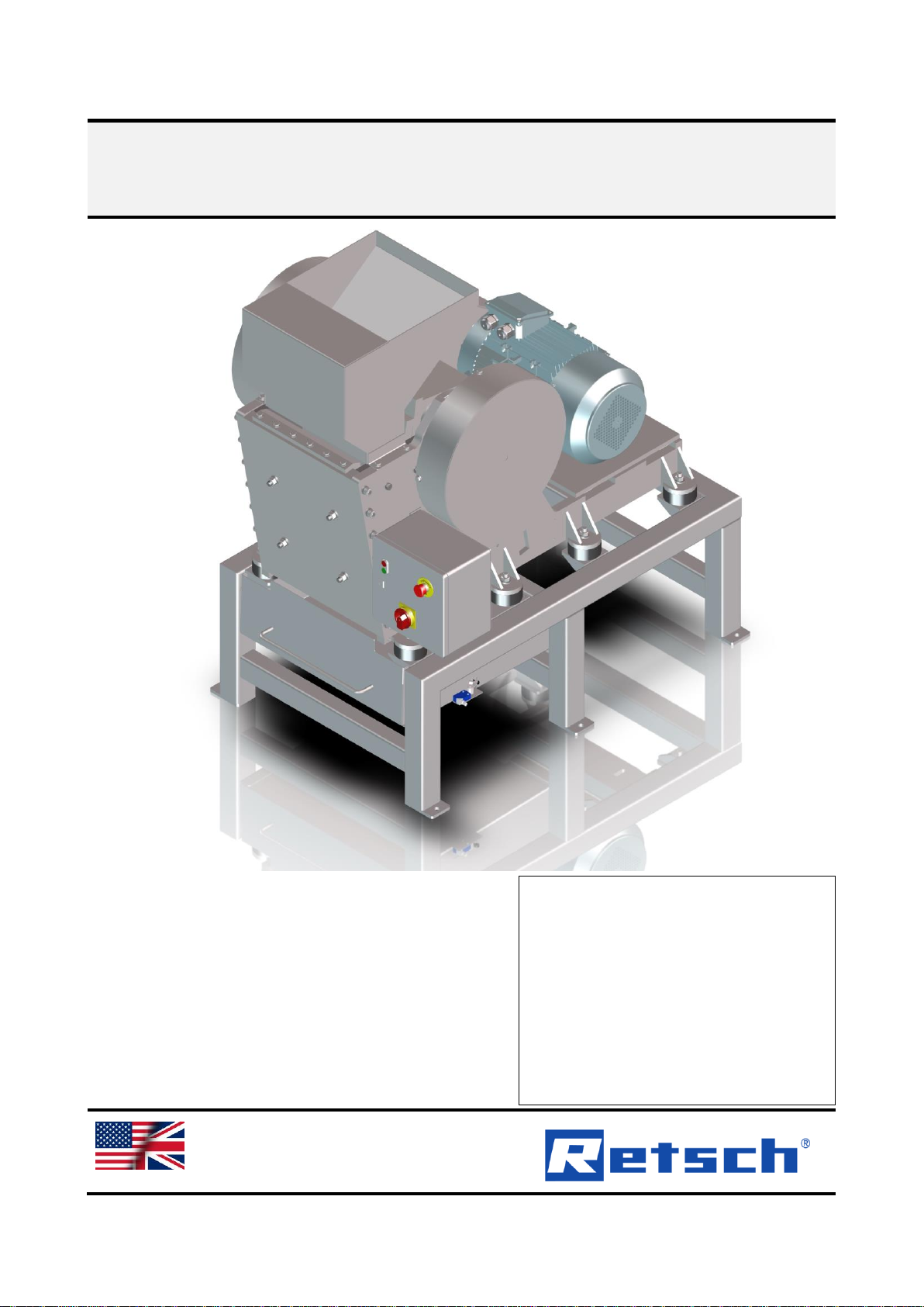
Jaw Crusher BB 600
Translation
Page 2

2
Copyright
© Copyright by
Retsch GmbH
Retsch-Allee 1-5
42781 Haan
Germany
Page 3

3
Table of Contents
1 Notes on the manual ........................................................................................................................ 5
1.1 Disclaimer .................................................................................................................................... 5
1.2 Copyright ...................................................................................................................................... 5
1.3 Repairs ......................................................................................................................................... 6
2 Safety ................................................................................................................................................ 7
2.1 Explanations of the Safety Instructions .......................................................................................... 8
2.2 General Safety Instructions ........................................................................................................... 9
2.3 Protective Equipment .................................................................................................................. 10
2.4 Intended use............................................................................................................................... 10
2.5 Improper use .............................................................................................................................. 10
2.6 Confirmation Form for the Managing Operator ............................................................................ 11
3 Technical Data................................................................................................................................ 12
3.1 Use of the Device for the Intended Purpose ................................ ................................................ 12
3.2 Principle of Operation ................................................................................................................. 12
3.3 Dimensions and Weight .............................................................................................................. 12
3.4 Required Floor Space ................................................................................................................. 13
3.5 Installation drawing ..................................................................................................................... 14
3.6 Rated Power............................................................................................................................... 15
3.7 Degree of Protection ................................ ................................................................ ................... 15
3.8 Emissions ................................................................................................................................... 15
3.9 Electromagnetic Compatibility (EMC) .......................................................................................... 16
3.10 Feed Grain Size.......................................................................................................................... 16
3.11 Degree of hardness of the sample material ................................................................ ................. 16
3.12 Gap width ................................ ................................................................ ................................ ... 16
4 Packaging, Transport and Installation .......................................................................................... 17
4.1 Packaging .................................................................................................................................. 17
4.2 Transport .................................................................................................................................... 17
4.3 Temperature Fluctuations and Condensation .............................................................................. 19
4.4 Conditions for the Installation Site ............................................................................................... 19
4.5 Electrical Connection .................................................................................................................. 20
4.6 Type Plate Description ................................................................................................................ 21
5 Views of the device ........................................................................................................................ 22
5.1 Front........................................................................................................................................... 22
5.2 Back ................................................................................................ ................................ ........... 23
5.3 View of the control unit................................................................................................................ 24
6 First Commissioning...................................................................................................................... 25
6.1 Installation of the Device ................................................................................................ ............. 26
6.2 Establishing the power supply ..................................................................................................... 27
7 Operating the Device ..................................................................................................................... 28
7.1 Switching On / Off ....................................................................................................................... 29
7.2 Adjusting the gap width ............................................................................................................... 30
7.3 Adding sample material .............................................................................................................. 32
7.4 Removing sample material after grinding .................................................................................... 33
8 Cleaning, Wear and Maintenance .................................................................................................. 35
8.1 Cleaning ................................................................................................................................ ..... 35
8.1.1 Cleaning the machine housing ................................................................................................ 36
8.1.2 Cleaning the feed hopper and grinding chamber ..................................................................... 36
8.2 Wear .......................................................................................................................................... 37
8.2.1 Replacing the breaking jaws ................................................................................................... 37
8.2.2 Replacing the wearing plates .................................................................................................. 40
8.3 Maintenance ............................................................................................................................... 42
Page 4

4
8.3.1 Lubricating the device ............................................................................................................. 42
8.3.2 Checking the limit switch ......................................................................................................... 43
8.4 Return for Service and Maintenance ........................................................................................... 44
9 Accessories.................................................................................................................................... 45
10 Disposal.......................................................................................................................................... 46
11 Index ................................................................ ................................................................ ............... 47
Page 5

Notes on the manual
5
1 Notes on the manual
This manual provides technical guidelines for the safe operation of the device. Read this
manual through carefully before installing, putting into service and operating the device.
Reading and understanding this manual is essential for handling the device safely and as
intended.
This manual does not contain any repair instructions. Please contact your supplier or contact
Retsch GmbH directly if anything is unclear or you have questions about these guidelines or the
device, or in the case of any faults or necessary repairs.
You can find further information about your device at http://www.retsch.com on the pages for
the specific device concerned.
Amendment status:
The document amendment 0001 of the "Jaw Crusher BB 600" manual has been prepared in
accordance with the Machinery Directive 2006/42/EC.
1.1 Disclaimer
This manual has been prepared with great care. We reserve the right to make technical
changes. We assume no liability for personal injuries resulting from the failure to follow the
safety information and warnings in this manual. No liability will be assumed for damage to
property resulting from the failure to follow the information in this manual.
1.2 Copyright
This document or parts of it or its content may not be reproduced, distributed, edited or copied
in any form without prior written permission of Retsch GmbH. Damage claims shall be asserted
in the case of infringements.
Page 6

Notes on the manual
6
1.3 Repairs
This manual does not contain any repair instructions. For safety reasons, repairs may only be
carried out by Retsch GmbH or an authorised representative or by qualified service technicians.
In case of repair, please inform…
…the Retsch GmbH representative in your country,
…your supplier, or
…Retsch GmbH directly.
Service address:
Page 7

Safety
7
2 Safety
Safety Officer
The operating company itself must ensure the following with respect to persons authorised to
work on the device:
− that they have read and understood all regulations contained in the chapter on safety;
− that they are aware before they start work of all instructions and regulations for the target
group related to the work;
− that they have easy access to the manual for this device at all times;
− that they have been familiarised with the safe and correct handling of the device before
starting work on it, by means of a verbal introduction by a competent person and/or using
this manual.
Improper operation can lead to personal injuries. The operating company itself is
responsible for its safety and that of its staff. The operating company itself must ensure that no
unauthorised persons have access to the device.
Target group
All those operating, cleaning or working with or on the device.
This device is a modern, powerful product from Retsch GmbH and has been developed in line
with the state-of-the art. The device is safe to use when operated correctly and when following
the instructions in this manual.
People under the influence of intoxicating substances (medications, drugs, alcohol) or who
are overtired may not operate the device or work on the device.
Page 8
Safety
8
2.1 Explanations of the Safety Instructions
The following warnings in this manual warn of possible risks and damage:
DANGER
D1.0000
Risk of fatal injuries
Source of danger
− Possible consequences if the danger is ignored.
• Instructions and information on how to avoid the risk.
Fatal or serious injuries may result if the “Danger” sign is disregarded. There is a very high
risk of a life-threatening accident or lasting personal injury. The signal word DANGER is
additionally used in the running text or in instructions.
WARNING
W1.0000
Risk of life-threatening or serious injuries
Source of danger
− Possible consequences if the danger is ignored.
• Instructions and information on how to avoid the risk.
Life-threatening or serious injuries may result if the “Warning” sign is disregarded. There is
an increased risk of a serious accident or of a possibly fatal personal injury. The signal word
WARNING is additionally used in the running text or in instructions.
CAUTION
C1.0000
Risk of injuries
Source of danger
− Possible consequences if the danger is ignored.
• Instructions and information on how to avoid the risk.
Average to slight injuries may result if the “Caution” sign is disregarded. There is an average
or slight risk of an accident or personal injury. The signal word CAUTION is additionally
used in the running text or in instructions.
Page 9

Safety
9
NOTICE
N1.0000
Type of damage to property
Source of the damage to property
− Possible consequences if the information is ignored.
• Instructions and information on how to avoid the damage to
property.
Damage to property may result if the information is disregarded. The signal word NOTICE is
additionally used in the running text or in instructions.
2.2 General Safety Instructions
CAUTION
C2.0002
Risk of injury
Lack of knowledge of the manual
− The manual contains all safety-related information. Disregarding the
manual can therefore lead to injuries.
• Read the manual carefully before operating the device.
CAUTION
C3.0015
Risk of injury
Improper modifications to the device
− Improper modifications to the device can result in injuries.
• Do not make any unauthorised changes to the device.
• Only use the spare parts and accessories approved by Retsch
GmbH!
NOTICE
N2.0012
Changes to the device
Improper modifications
− The conformity declared by Retsch GmbH with the European Directives
will lose its validity.
− Any warranty claims will be terminated.
• Do not make any modification to the device.
• Use spare parts and accessories that have been approved by Retsch
GmbH exclusively.
Page 10

Safety
10
2.3 Protective Equipment
• The Jaw Crusher BB 600 can only be started when the collecting receptacle has been
inserted into the base frame.
• A limit switch behind the collecting receptacle prevents the machine starting in an unsafe
state.
• Removing the collecting receptacle results in the grinding process stopping immediately.
• The motor protection switch turns the drive motor off when the jaws are blocked.
• In the event of danger, the machine can be shut down at any time by pressing the
emergency stop button .
2.4 Intended use
The Jaw Crusher BB 600 is suitable for grinding medium to extremely hard substances and for
brittle and hard ductile materials.
The machine has been designed for 8-hour single shift operation. Use is only permitted in the
laboratory by appropriately trained and qualified staff.
2.5 Improper use
The Jaw Crusher BB 600 is not designed for continuous operation. Use in the private sphere
and for applications other than those set out in the “Intended use” chapter is not permitted.
Repairs and modifications may only be carried out by Retsch GmbH by an authorised
representative, or by qualified service technicians.
Page 11

Safety
11
2.6 Confirmation Form for the Managing Operator
This manual contains essential instructions for operating and maintaining the device which must
be strictly observed. It is essential that they be read by the user and by the qualified staff
responsible for the device before the device is commissioned. This manual must be available
and accessible at the place of use at all times.
The user of the device herewith confirms to the managing operator (owner) that he has received
sufficient instructions about the operation and maintenance of the system. The user has
received the manual, has read and taken note of its contents and consequently has all the
information required for safe operation and is sufficiently familiar with the device.
The managing operator should for legal protection have the user confirm the instruction about
the operation of the device.
I have read and taken note of the contents of all chapters in this manual as well as all
safety instructions and warnings.
User
Surname, first name (block letters)
Position in the company
Place, date and signature
Managing operator or service technician
Surname, first name (block letters)
Position in the company
Place, date and signature
Page 12

Technical Data
12
3 Technical Data
3.1 Use of the Device for the Intended Purpose
Das
The Jaw Crusher BB 600 is suitable for grinding medium to medium-hard substances and brittle
and hard ductile materials.
The machine can be used to grind the following materials:
• Concrete
• Ores
• Rocks
• Glass
• Ceramics
• Coal
• Minerals
• Slag
• Cement clinker
NOTICE
N3.0007
Range of application of the device
Long-term operation
− This laboratory device is designed for eight-hour single-shift operation
with a duty cycle of 30 %.
• This device may not be used as a production machine nor is it
intended for continuous operation.
3.2 Principle of Operation
The Jaw Crusher BB 600 is tough and powerful.
The feed material passes through the splash-free hopper and into the grinding chamber.
Grinding takes place in the wedge-shaped shaft between the jaws. The feed material is
crushed and moved downwards by the elliptical motion.
The sample falls into a removable collecting receptacle as soon as it is finer than the smallest
discharge gap width.
The infinitely variable adjustment of the gap width ensures an optimum setting for the feed
material and for the desired final fineness level.
3.3 Dimensions and Weight
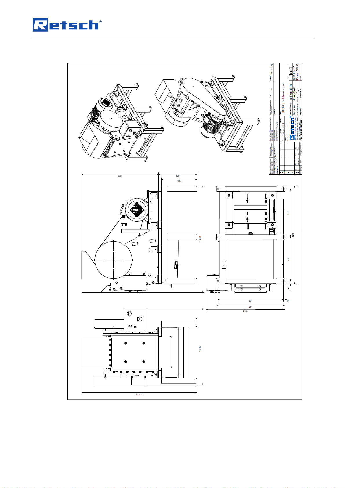
Height: ~1,575 mm
Width: ~1,073 mm
Depth: ~1,456 mm
Weight: ~1,300 kg net
Page 13

Technical Data
13
3.4 Required Floor Space
Width of floorspace: 1,080 mm
Depth of floorspace: 1,500 mm
No safety distance is required!
A space of around 50 cm should be planned on the left-hand side of the machine for better
operability.
Page 14
Technical Data
14
3.5 Installation drawing
Fig. 1: Installation drawing
Page 15
Technical Data
15
3.6 Rated Power
15000 watts
3.7 Degree of Protection
− IP 55
3.8 Emissions
Noise data
Noise measurement in accordance with DIN 45635-31-01-KL3
Noise levels are significantly influenced by the properties of the sample material.
Example 1:
Sound power level LWA = 101.7 dB(A)
Workplace-related emissions value L
pAeq
= 89.5 dB(A)
Operating conditions :
Feed material : marble pebbles, particle size <90 mm
Set gap width: < 6 mm
Final particle size: < 10 mm
Fill level of the grinding chamber: approx. 65 %
Example 2:
Sound power level LWA = 102 dB(A)
Workplace-related emissions value L
pAeq
= 90 dB(A)
Operating conditions:
Feed material: quartz pebbles, particle size <55 mm
Set gap width: < 6 mm
Final particle size: < 10 mm
Fill level of the grinding chamber: approx. 65 %
CAUTION
C4.0045
Damage to hearing
A high noise level may arise depending on the type of the material, the jaws
used and the duration of grinding
− Excessive noise in terms of level and duration can cause impairments or
lasting damage to hearing.
• Suitable sound insulation measures must be provided or hearing
protection worn.
Page 16

Technical Data
16
3.9 Electromagnetic Compatibility (EMC)
− EMC class in accordance with DIN EN 55011: B
3.10 Feed Grain Size
Feed size: < 350x170 mm
Final fineness: < 6 mm
3.11 Degree of hardness of the sample material
The degree of hardness of the sample material should be above 3 on the Mohs’ scale to
achieve effective grinding. The degree jaws should be harder than the sample material to
prevent increased wear on the jaws.
3.12 Gap width
The spacer plates permit a gap width adjustment of between 6 mm and approx. 60 mm:
Spacer plates [mm]
Gap opening [mm]
-
62 5 58
10
47
15
38
20
33
25
25
30
18
35
12
37 (maximum)
6
Page 17

Packaging, Transport and Installation
17
4 Packaging, Transport and Installation
4.1 Packaging
The packaging has been adapted to the mode of transport. It complies with the generally
applicable packaging guidelines.
NOTICE
N4.0001
Complaint or return
Keeping the packaging
− Inadequate packaging and insufficient securing of the device can
jeopardise the warranty claim in the event of a complaint or return.
• Keep the packaging for the duration of the warranty period.
4.2 Transport
DANGER
D2.0001
Serious personal injury
Suspended loads
− If dropped, the great weight of the device would result in serious injuries
or death.
• People must never stand below suspended loads!
WARNING
W2.0011
Serious injuries
Excessive weight
• The machine is extremely heavy, weighing 1300 kg, and can lead to
serious injuries when lifted.
• The machine may only be lifted and transported using lifting gear!
NOTICE
N5.0017
Damage to components
Transport
− Mechanical or electronic components may be damaged during transport.
• The device must not be knocked, shaken or thrown during transport.
Page 18

Packaging, Transport and Installation
18
NOTICE
N6.0014
Complaints
Incomplete delivery or transport damage
− The forwarding agent and Retsch GmbH must be notified immediately in
the event of transport damage. It is otherwise possible that subsequent
complaints will not be recognised.
• Please check the delivery on receipt of the device for its
completeness and intactness.
• Notify your forwarding agent and Retsch GmbH within 24 hours.
Fig. 2: Transport bolts
The Jaw Crusher BB 600 can be transported using a crane or other suitable means of transport:
• To do this, wind ropes through the two transport bolts (TS) on the machine.
CAUTION Only use suitable lifting gear that has been approved for the weight of the device.
The BB 600 has a base frame (Z) using which the device can be lifted and transported with the
help of lifting gear.
Move lifting gear such as a forklift under the base frame (Z).
Slowly lift the device using the lifting gear and stabilise it to prevent it from toppling over.
Fig. 3: Base frame
TS
TS
Z
Page 19

Packaging, Transport and Installation
19
4.3 Temperature Fluctuations and Condensation
NOTICE
N7.0016
Damaged components due to condensation
Temperature fluctuations
− The device may be exposed to substantial fluctuations in temperature
during transport. The ensuing condensation can damage electronic
components.
• Wait until the device has acclimatised before putting it into service.
Temporary storage:
Also in case of an interim storage the device must be stored dry and within the specified
ambient temperature range.
4.4 Conditions for the Installation Site
− Installation height: max. 2 000 m above sea level
− Ambient temperature: 5 °C – 40 °C
NOTICE
N8.0021
Ambient temperature
Temperatures outside the permitted range
− Electronic and mechanical components may be damaged.
− The performance data alter to an unknown extent.
• Do not exceed or fall below the permitted temperature range (5 °C to
40 °C ambient temperature) of the device.
− Maximum relative humidity < 80 % (at ambient temperatures ≤ 31 °C)
For ambient temperatures UT between 31 °C and 40 °C, the maximum relative humidity value LF
linearly decreases according to LF = –(UT – 55) / 0.3:
Ambient temperature
Max. rel. humidity
≤ 31 °C
80 %
33 °C
73.3 %
35 °C
66.7 %
37 °C
60 %
39 °C
53.3 %
40 °C
50 %
Page 20

Packaging, Transport and Installation
20
NOTICE
N9.0015
Humidity
High relative humidity
− Electronic and mechanical components may be damaged.
− The performance data alter to an unknown extent.
• The relative humidity in the vicinity of the device should be kept as
low as possible.
4.5 Electrical Connection
WARNING
W3.0005
Danger to life due to electric shock or fire
Incorrect connection to the power supply may result in parts of the housing or
cables being live and in fires starting.
− Serious injuries or death due to an electric shock.
− Serious injuries or death due to fires.
• The device may only be connected by a qualified electrician.
NOTICE
N10.0022
Electrical connection
Failure to observe the values on the type plate
− Electronic and mechanical components may be damaged.
• Connect the device only to a mains supply matching the values on
the type plate.
− Information about the required voltage and frequency of the device can be found on the
type plate .
− The device may only be connected to the power supply using the connection cable
supplied.
− The circuit breaker for connecting the power cable to the power supply at the installation
site should be suitable for higher start-up current and correspond to a type C
characteristic (slow blow fuse).
NOTICE
N11.0005
Electrical connection
Wrong direction of rotation on drive motor
− Electronic and mechanical components may be damaged.
− Insufficient grinding of the sample material.
• Before putting into operation for the first time, check whether the
direction of rotation of the motor (fan direction of rotation) complies
with the direction arrow on the belt cover.
Page 21

Packaging, Transport and Installation
21
4.6 Type Plate Description
Fig. 1: Type plate
1 Device designation
2 Year of production
3 Part number
4 Serial number
5 Manufacturer’s address
6 CE marking
7 Disposal label
8 Bar code
9 Power version
10 Mains frequency
11 Capacity
12 Amperage
13 Number of fuses
14 Fuse type and fuse strength
In the case of queries please provide the device designation (1) or part number (3), as well
as the serial number (4) of the device.
1
2
3
4
5
6
7 8 9
10
11
12
14
13
Page 22

Views of the device
22
5 Views of the device
5.1 Front
Fig. 4: Front view
Element
Description
Function
A
Feed hopper
For adding material.
B
Control element
For operating and controlling the machine.
C
Collecting receptacle
Collects the sample material.
The limit switch in the base frame actuates if the
collecting receptacle is removed during operation.
A
B
C
Page 23

Views of the device
23
5.2 Back
Fig. 5: Rear view
Element
Description
Function
D
Lock nuts
Counter the spacer plates when adjusting the gap
E
Spring
For adjusting the gap
E
D
Page 24

Views of the device
24
5.3 View of the control unit
Fig. 6: Control element
Element
Description
Function
F
On/Off switch
Switches the jaw crusher on or off.
G
Emergency stop button
Stops the machine in the event of danger.
H
Main switch
Switches the machine on or off.
F G H
Page 25

First Commissioning
25
6 First Commissioning
WARNING
W4.0002
Danger to life through electric shock
Damaged power cable
− Operating the device with a damaged power cable or plug can lead to lifethreatening injuries caused by an electric shock.
• Before operating the device, check the power cable and plug for
damage.
• Never operate the device with damaged power cable or plug!
WARNING
W5.0004
Danger to life due to electric shock
Electrically conductive parts of the housing due to contact with live cables inside
the housing
− An electric shock can result in burns, cardiac arrhythmia, respiratory
arrest and cardiac arrest.
• Always operate the device using a mains socket protected by a
residual current circuit breaker (RCCB).
NOTICE
N12.0002
Setting up the device
Disconnecting the device from the mains
− A separation of the device from the mains must be possible at any time.
• Set up the device in such a way, that the connection for the power
cable is always easily accessible.
NOTICE
N13.0004
Setting up the device
Vibrations during operation
− Depending on the operating mode of the device, slight vibrations may
occur.
• Set up the device only on a vibration-free, plane and stable surface.
Page 26

First Commissioning
26
6.1 Installation of the Device
Fig. 7: Securing to the transport pallet
On delivery, the Jaw Crusher BB 600 is screwed to the transport pallet.
• Remove the hex screws (SC) from the transport pallet.
• Using a forklift, lift the machine up.
• Secure the supplied stands (vibration absorbers) to the base frame.
• Place the machine onto the intended installation surface.
If the machine is installed without the stands (vibration absorbers), it must be screwed to a level,
firm base.
• Screw the machine firmly onto the base using suitable hex screws (SC).
Fig. 2: Device feet: do not push or pull device
NOTICE
N14.0002
Damage to the device feet
Pushing or pulling the device
− If the device is pushed or pulled across a surface, this can damage the
device feet (vibration dampers).
• Do not pull or push the device.
• Lift the device if you need to move it.
SC
Page 27

First Commissioning
27
6.2 Establishing the power supply
WARNING
W6.0005
Danger to life due to electric shock or fire
Incorrect connection to the power supply may result in parts of the housing or
cables being live and in fires starting.
− Serious injuries or death due to an electric shock.
− Serious injuries or death due to fires.
• The device may only be connected by a qualified electrician.
The Jaw Crusher BB 600 is connected to the power supply as follows:
• Ensure that the machine has been securely installed; see “Installation of the Device”.
• Using the connecting cable provided, connect the machine to the operator’s power supply.
Also see “Electrical Connection”.
• When doing so comply with local regulations and safety measures.
Page 28

Operating the Device
28
7 Operating the Device
CAUTION
C5.0005
Risk of injury
Potentially explosive atmosphere
− The device is not suitable for use in potentially explosive atmospheres.
Operating the device in a potentially explosive atmosphere can lead to
injuries caused by an explosion or fire.
• Never operate the device in a potentially explosive atmosphere!
CAUTION
C6.0006
Risk of injury
Sample material that is harmful to health
− Sample material that is harmful to health can injure people (illness,
contamination).
• Use suitable extraction systems with sample material that is
harmful to health.
• Use suitable personal protective equipment with sample material
that is harmful to health.
• Take note of the safety data sheets for the sample material.
CAUTION
C7.0010
Risk of burns or poisoning
Varying sample properties
− The properties and therefore also the chemical reactivity of the sample
can change during the grinding process and can cause burns or poisoning
as a result.
• Do not process any substances in this device whose chemical
reactivity is so changed by grinding that there is a risk of explosion
or poisoning.
• Take note of the safety data sheets for the sample material.
CAUTION
C8.0004
Risk of injury
Explosive or flammable samples
− Samples can explode or catch fire during the grinding process.
• Do not use any samples in this device that carry a risk of explosion
or fire.
• Take note of the safety data sheets for the sample material.
Page 29

Operating the Device
29
NOTICE
N15.0007
Range of application of the device
Long-term operation
− This laboratory device has been designed for 8-hour single shift operation.
• This device must not be used as a production machine or deployed
in continuous operation.
NOTICE
N16.0000
Selection of suitable materials
− You might be using unsuitable materials.
• Use the manufacturer’s application database to check whether
your sample material is suitable for use.
7.1 Switching On / Off
NOTICE The Jaw Crusher BB 600 may only be started up with an empty crushing chamber.
Grinding material placed in the crushing chamber or the feed hopper before starting the
machine will result in a blockage and possibly damage to mechanical components.
The control unit is located on the front of the Jaw Crusher BB 600, see “View of the control unit”.
Start the machine as follows:
• Turn the main switch (H) to the “ON” position and release the emergency stop button (G)
where applicable.
• Switch the machine on using the green button (F).
The motor is started up and the moving crusher arm is set in motion.
The grinding process can only be started if the drawer on the collecting receptacle (C) (see
“Front view”) has been completely pushed in. Please ensure that you close and lock the drawer
in order to prevent it slipping out due to vibrations.
When open, a limit switch prevents the machine starting (also see (C) in “Front view.
NOTICE Stop the Jaw Crusher BB 600 when there is no longer any grinding material in the
crushing chamber.
Mechanical components may be damaged by a possible blockage.
The control unit is on the front of the Jaw Crusher BB 600, see “View of the control unit”.
The machine is switched off as follows:
• Switch the machine off using the red knob (F).
• Turn the main switch (H) to the “OFF” position.
In an emergency: the machine is shut down immediately when the emergency stop button (G)
is pressed.
The motor is disconnected from the power supply and the moving crusher arm comes to a halt.
Page 30

Operating the Device
30
7.2 Adjusting the gap width
Fig. 8: Adjusting the gap width
The gap width can be adjusted as follows:
• Turn the Jaw Crusher BB 600 off at the main switch (H) (see “View of the control element“).
• Disconnect the machine from the power supply and secure to prevent it restarting.
• Unscrew the outer lock nuts (DML) and (DMR).
Wrench opening SW 36.
• Unscrew the middle lock nut (DMM).
Wrench opening SW 30.
• Screw in the middle screw (DSM), wrench opening SW 30.
Ensure that the spring (E) is tensioned at all times.
• Insert the desired combination of spacer plates (DB).
The gap will be wider when you remove the spacer plates and will be narrower when you
insert the spacer plates. Also see “Gap width”.
Fig. 9: Spacer plates
DSM
DML
DMM
DMR
DB
E
Page 31

Operating the Device
31
• Unscrew the middle screw (DSM).
Ensure that the spring (E) is tensioned at all times.
• Tighten the outer lock nuts (DML) and (DMR).
Torque approx. 190 Nm.
• Tighten the middle lock nut (DMM).
Torque approx. 110 Nm.
• Adjust the spring pre-load so that the spring is 55 mm long.
Wrench opening SW 30.
Fig. 10: Spring pre-load
Page 32

Operating the Device
32
7.3 Adding sample material
CAUTION
C9.0045
Damage to hearing
A high noise level may arise depending on the type of the material, the jaws
used and the duration of grinding
− Excessive noise in terms of level and duration can cause impairments or
lasting damage to hearing.
• Suitable sound insulation measures must be provided or hearing
protection worn.
NOTICE
N17.0003
Damage to mechanical components
Overfilling the feed hopper and the grinding chamber
− Feeding too much sample material can result in increased wear to the
jaws and wearing plates and to blockages.
• Do not use the feed hopper for storing sample material.
• Do not fill the grinding chamber to over 65% full.
• Do not exceed the specified maximum feed size for the sample
material.
• Fill larger and firmer sample material slowly and gradually into the
feed hopper.
• Pre-grind larger and firmer sample material with a larger gap where
necessary.
NOTICE Filling the crushing chamber to more than 2/3 full may damage the guide plates on the
feed hopper (A) and will result in sample material being conveyed by the activated crusher arm
into the crusher housing behind the crusher arm.
The fill volume also influences the fine share in the pre-ground sample. The fuller the crushing
chamber, the higher the fine share may be.
NOTICE With respect to the fill level, attention should also always be paid to the volume of the
collecting receptacle (D). The fill quantity must not exceed the volume of the collecting
receptacle (D).
NOTICE Only fill the feed hopper (A) and the crushing chamber when the machine is in operation.
The feed hopper (A) is not intended for storing sample material, rather its sole purpose is for
feeding the material into the crushing chamber. It furthermore prevents inadvertent access to the
crushing chamber and holds back any splashing sample material.
Page 33

Operating the Device
33
7.4 Removing sample material after grinding
CAUTION
C10.0005
Burns
Heating of the sample material during grinding
− Hot surfaces on the collecting receptacle or the grinding chamber can
cause burns.
− Hot sample material in the collecting receptacle can cause burns.
• Allow the hot sample material to cool down before removing the
collecting receptacle and opening the door.
• Wear protective gloves.
CAUTION
C11.0010
Heavy collecting receptacle
Depending on the density of the sample material or the filling level, the filled
collecting receptacle may be very heavy.
− Due to its weight, a filled collecting receptacle can cause personal injuries
when lifted out from the base frame.
• As a general rule, always use both hands to pull the collecting
receptacle out of the base frame.
• Two people should always remove a heavy collecting receptacle
from the base frame.
• Wear safety shoes.
NOTICE
N18.0004
Damage to mechanical components
Jaw blockage with the motor shutting down
− Due to the size and geometry of the grinding chamber, blockages may
occur when feeding a large quantity of big pieces of firmer sample
material. If the machine is not switched off in time in the event of
blockages, a motor protection switch turns the overloaded drive motor off.
• Switch the machine off immediately when there is a blockage and
remove the sample material causing the blockage.
• Reduce the feed of sample material to the feed hopper.
• Fill larger and firmer sample material slowly and gradually into the
feed hopper.
• If necessary, pre-grind larger and firmer sample material using a
larger gap width.
Page 34

Operating the Device
34
Fig. 11: Collecting receptacle
• Switch the Jaw Crusher BB 600 off.
• Pull the collecting receptacle (C) out of the base frame.
• Remove the ground sample material from the collecting receptacle (C).
C
Page 35

Cleaning, Wear and Maintenance
35
8 Cleaning, Wear and Maintenance
CAUTION
C12.0013
Risk of injury
Improper repairs
− Unauthorised and improper repairs can cause injuries.
• Repairs to the device may only be carried out by the Retsch GmbH ,
an authorised representative or by qualified service technicians.
• Do not carry out any unauthorised or improper repairs to the device!
8.1 Cleaning
WARNING
W7.0003
Risk to life caused by an electric shock
Cleaning live parts with water
− Cleaning the device with water can lead to life-threatening injuries caused
by an electric shock if the device has not been disconnected from the
power supply.
• Only carry out cleaning work on the device when it has been
disconnected from the power supply.
• Use a cloth moistened with water for cleaning.
• Do not clean the device under running water!
CAUTION
C13.0031
Risk of injury
Cleaning with compressed air
− When using compressed air for cleaning purposes dust and remnant of
the sample material can be flung around and injure eyes.
• Always wear safety glasses when cleaning with compressed air.
• Observe the material safety data sheets of the sample material.
NOTICE
N19.0009
Damage to the housing and device
Use of organic solvents
− Organic solvents may damage plastic parts and the coating.
• The use of organic solvents is not permitted.
Page 36

Cleaning, Wear and Maintenance
36
8.1.1 Cleaning the machine housing
The machine is best cleaned using an industrial vacuum cleaner and brush with a long handle:
• Clean the housing of the Jaw Crusher BB 600 with a damp cloth and standard household
detergent.
• Ensure that no water or detergent gets inside the machine.
8.1.2 Cleaning the feed hopper and grinding chamber
WARNING
W8.0003
Serious personal injury
Contact between moving jaws in the grinding chamber
− Accidentally reaching into the grinding chamber and between moving jaws
can cause serious injuries to hands.
• Always operate the device with the feed hopper installed.
Fig. 12: Feed hopper
• Turn the Jaw Crusher BB 600 off by the main switch (H) (see “View of the control unit”).
• Disconnect the machine from the power supply and secure to prevent it restarting.
• Unscrew the four hex screws (S) around the feed hopper (A).
• Lift the feed hopper (A) up and off.
• Clean the feed hopper (A) using a damp cloth and household detergent.
• Clean the grinding chamber and jaws with a brush and vacuum the loosened material
residue with an industrial vacuum cleaner.
• The grinding chamber may alternatively be carefully cleaned with compressed air.
• After cleaning, replace the feed hopper above the grinding chamber.
• Secure the feed hopper (A) again using the four hex screws (S).
A
S
Page 37

Cleaning, Wear and Maintenance
37
8.2 Wear
CAUTION
C14.0013
Risk of injury
Improper repairs
− Unauthorised and improper repairs can cause injuries.
• Repairs to the device may only be carried out by the Retsch GmbH ,
an authorised representative or by qualified service technicians.
• Do not carry out any unauthorised or improper repairs to the device!
Jaws may wear depending on the frequency of grinding and the property of the sample material.
The jaws and the wearing plates should be inspected regularly for wear and replaced where
necessary.
8.2.1 Replacing the breaking jaws
The jaws on the Jaw Crusher BB 600 are replaced as follows:
• Turn the machine off by the main switch (H) (see “View of the control unit”).
• Disconnect the machine from the power supply and secure to prevent it restarting.
Fig. 13: Feed hopper
• Unscrew the four hex screws (S) for the feed hopper (A).
• Lift the feed hopper (A) up and off.
• Set the gap width to maximum.
To do this, unscrew the lock nuts and remove the spacer plates (see “Adjusting the gap
width”).
A
S
Page 38

Cleaning, Wear and Maintenance
38
Fig. 14: Removing the cover plates
• Loosen the screws (AS) and remove the cover plates (P).
Fig. 15: Unscrewing the fixing screws
• Unscrew the four fixing screws (FS) on both jaws.
• Gently tap the surface of the jaws so that they come away from the support and slide
downwards.
P
P
AS
AS
FS
Page 39

Cleaning, Wear and Maintenance
39
Fig. 16: Removing the jaws
• Remove the jaws using the supplied lifting pins (TH).
The worn jaws have been removed and the new jaws can be inserted in reverse order.
TH
Page 40

Cleaning, Wear and Maintenance
40
8.2.2 Replacing the wearing plates
Proceed as follows to replace the wearing plates:
• Remove the feed hopper, see “Cleaning the feed hopper and grinding chamber”.
Fig. 17: Wearing plate fastening
• Unscrew the four fixing screws (SBS) on each wearing plate (SB).
Fig. 18: Wearing plate fastening
• Screw one eyebolt (RS) into each designated drill hole at the top of the wearing plate (RS).
• Lift the wearing plates (SB) slightly to release them.
SB
SBS
RS
SB
Page 41

Cleaning, Wear and Maintenance
41
• Using a crane, lift the wearing plates out from the crushing chamber by the eyebolts.
The wearing plates have been removed and the new wearing plates can be inserted in
reverse order.
Page 42

Cleaning, Wear and Maintenance
42
8.3 Maintenance
CAUTION
C15.0013
Risk of injury
Improper repairs
− Unauthorised and improper repairs can cause injuries.
• Repairs to the device may only be carried out by the Retsch GmbH ,
an authorised representative or by qualified service technicians.
• Do not carry out any unauthorised or improper repairs to the device!
8.3.1 Lubricating the device
The Jaw Crusher BB 600 must be lubricated again after around 60 operating hours:
Fig. 19: Lubrication points
• Apply a sufficient amount of grease (approx. 4 to 7 g) to the marked lubrication points (SP).
• Use natural coloured, lithium saponified and graphite-free grease, such as Shell Gadus S2
V220 2 or BP Energrease LS-EP 2 as lubricant.
• Apply the grease to the lubrication points using a standard grease press.
SP
SP
Page 43

Cleaning, Wear and Maintenance
43
8.3.2 Checking the limit switch
A functional inspection of the limit switch must be conducted every 6 months.
Check the function of the limit switch as follows:
• Start the Jaw Crusher BB 600.
• Open the draw on the collecting receptacle (D), see “Front view”.
The limit switch must activate, and the machine must stop or coast to a halt.
• Close the drawer on the collecting receptacle (D).
The machine must not start up.
• Turn the machine on by the main switch (H).
The machine starts and runs normally.
Page 44

Cleaning, Wear and Maintenance
44
8.4 Return for Service and Maintenance
Fig. 20: Return form
The acceptance of devices and accessories of the Retsch GmbH for repair, maintenance or
calibration can only be effected, if the return form including the decontamination declaration
service has been correctly and fully completed.
Download the return form located in the download section "Miscellaneous" on the Retsch
GmbH homepage (http://www.retsch.com/downloads/miscellaneous/).
When returning a device, attach the return form to the outside of the packaging.
In order to eliminate any health risk to the service technicians, Retsch GmbH reserves the right
to refuse the acceptance and to return the respective delivery at the expense of the sender.
Page 45

Accessories
45
9 Accessories
Information on available accessories as well as the respective manuals are accessible directly
on the Retsch GmbH homepage (http://www.retsch.com) under the heading "Downloads" of the
device.
Information on wear parts and small accessories can be found in the Retsch GmbH general
catalogue also available on the homepage.
In case of any questions concerning spare parts please contact the Retsch GmbH
representative in your country, or Retsch GmbH directly.
Page 46

Disposal
46
10 Disposal
In the case of a disposal, the respective statutory requirements must be observed. In the
following, information on the disposal of electrical and electronic devices in the European
Community are given.
Within the European Community the disposal of electrically operated devices is regulated by
national provisions that are based on the EU Directive 2012/19/EU on Waste Electrical and
Electronic Equipment (WEEE).
Accordingly, all devices supplied after August 13th 2005 in the business-to-business area, to
which this product is classified, may no longer be disposed of with municipal or household
waste. To document this, the devices are provided with the disposal label.
Fig. 3: Disposal label
Since the disposal regulations worldwide and also within the EU may differ from country to
country, the supplier of the device should be consulted directly in case of need.
This labelling obligation is applied in Germany since March 23rd 2006. From this date on, the
manufacturer must provide an adequate possibility of returning all devices delivered since
August 13th 2005. For all devices delivered before August 13th 2005 the end user is responsible
for the proper disposal.
Page 47

Index
47
11 Index
A
Accessories ......................................................46
Adjusting the gap width .....................................31
Adjusting the gap width .....................................30
Ambient temperature.........................................20
Amendment status ..............................................6
Amperage .........................................................22
B
Back .................................................................24
Bar code ................................ ...........................22
Base frame .......................................................19
Burns ................................................................34
C
Calibration ........................................................45
Capacity ...........................................................22
CE marking .......................................................22
Circuit breaker ..................................................21
Cleaning ...........................................................36
Cleaning the feed hopper ..................................37
Cleaning the grinding chamber ..........................37
Cleaning the machine housing ..........................37
Collecting receptacle ................................... 23, 35
Complaints.................................................. 18, 19
Condensation....................................................20
Confirmation form for the managing operator ....12
Control element .......................................... 23, 25
Copyright ............................................................6
D
Damage to hearing ..................................... 16, 33
Degree of hardness of the sample material .......17
Degree of protection .........................................16
Description
Back ..............................................................24
Front .............................................................23
Device designation............................................22
Device feet........................................................27
Dimensions .......................................................13
Depth ............................................................13
Height ...........................................................13
Weight ...........................................................13
Width.............................................................13
direction arrow ..................................................21
Disclaimer ...........................................................6
Disconnection from the mains ...........................26
Disposal............................................................47
label ........................................................ 22, 47
regulations ....................................................47
E
Electrical connection .........................................21
Electromagnetic compatibility ............................17
EMC .................................................................17
Emergency stop button .....................................11
Emissions .........................................................16
Establishing the power supply ...........................28
Explanations of the safety instructions .................9
F
Feed grain size .................................................17
Feed hopper ................................... 23, 33, 37, 38
First commissioning ..........................................26
Fixing screws for jaws .......................................40
Floorspace
Depth ............................................................14
Width.............................................................14
Frequency.........................................................21
Front .................................................................23
Front view .........................................................23
Fuse strength ....................................................22
Fuse type ..........................................................22
G
Gap width .........................................................17
General catalogue.............................................46
General safety instructions ................................10
H
Humidity ...........................................................21
I
Improper use ....................................................11
Installation ........................................................18
Establishing the power supply........................28
Installation drawing ...........................................15
Installation drawing ...........................................15
Installation height ..............................................20
Installation of the device ....................................27
Installation site
conditions ................................ ......................20
Intended use ................................ ..................... 11
L
Lift
with lifting gear ..............................................19
Limit switch .......................................................11
Checking .......................................................44
Long-term operation ..........................................30
Long-term operation ..........................................13
Lubrication points ..............................................43
M
Mains frequency ...............................................22
Mains supply .....................................................21
Maintenance ................................... 12, 36, 43, 45
lubricating......................................................43
Manual................................................................6
Manual..............................................................10
Manual..............................................................12
Manufacturer’s address .....................................22
Motor protection switch .....................................11
Page 48

Index
48
N
Noise level .................................................. 16, 33
Notes on the manual ...........................................6
Number of fuses ...............................................22
O
Operating instructions .......................................12
Operating the device .........................................29
P
Packaging .........................................................18
Part number ................................ ......................22
Power version ...................................................22
Principle of operation ........................................13
Protective equipment ........................................11
R
Range of application of the device .....................13
Range of application of the device .....................30
Rated power .....................................................16
Rear view..........................................................24
Relative humidity
maximum ......................................................20
Releasing the jaws ............................................39
Removing the cover plates ................................39
Repair ......................................... 7, 36, 38, 43, 45
Repair instructions ..............................................7
Replacing the breaking jaws..............................38
Replacing the wearing plates ............................41
Required floor space .........................................14
Return...............................................................18
for service and maintenance ..........................45
Return device....................................................47
Return form.......................................................45
S
Safety .................................................................8
Safety Officer ......................................................8
Sample material
adding ........................................................... 33
heated ...........................................................34
removing .......................................................34
Serial number ................................................... 22
Service address ..................................................7
Small accessories .............................................46
Spacer plates ....................................................31
Spare parts .......................................................46
Spring pre-load .................................................32
Switching on / off ..............................................30
T
Target group .......................................................8
Technical data ................................ ..................13
Temperature fluctuations...................................20
Temperature range ...........................................20
Temporary storage............................................20
Transport ..........................................................18
Transport bolts ..................................................19
Transport damage.............................................19
Transport pallet
Securing ........................................................27
Type C characteristic ........................................21
Type plate ................................................... 21, 22
description .....................................................22
U
Use of the device for the intended purpose........13
V
Vibrations .........................................................26
View of the control unit ......................................25
Views of the device ...........................................23
Voltage .............................................................21
W
Warning ..............................................................9
Information ................................ ....................10
Warranty claim ..................................................18
Warranty claims ................................................10
Wear ........................................................... 36, 38
Wear parts ........................................................46
Wearing plate fastening ....................................41
Wearing plate fastening ....................................41
Wearing plates ..................................................38
Weight ..............................................................13
Wrong direction of rotation motor ......................21
Y
Year of production.............................................22
Page 49

49
Page 50

Copyright
© Copyright by
Retsch GmbH
Retsch-Allee 1-5
42781 Haan
Germany
 Loading...