

Page 1
Manual
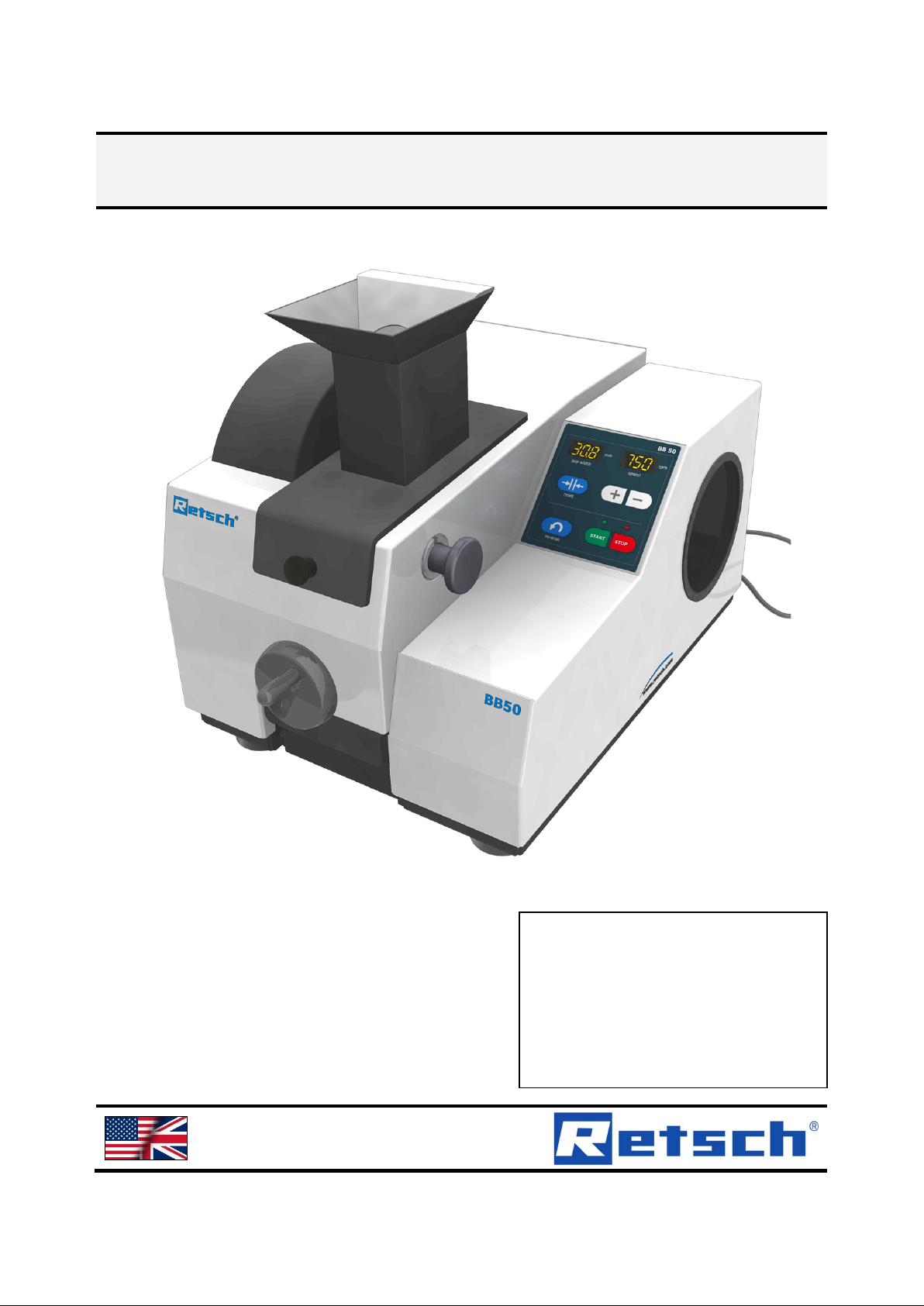
Jaw Crusher BB50
Translation
© Retsch GmbH, 42781 Haan, Retsch-Allee 1-5, Germany 10.02.2014 0001
Page 2

Copyright
© Copyright by
Retsch GmbH
Haan, Retsch-Allee 1-5
D-42781 Haan
Federal Republic of Germany
2
Page 3

3
Page 4

1 Notes on the Operating Manual ............................................................................................................ 6
1.1 Explanations of the safety warnings .................................................................................................. 7
1.2 General safety instructions ................................................................................................................ 8
1.3 Repairs ............................................................................................................................................... 9
2 Confirmation ......................................................................................................................................... 10
3 Technical data ....................................................................................................................................... 11
3.1 Use of the machine for the intended purpose.................................................................................. 11
3.1.1 Properties of the grinding material ............................................................................................... 11
3.2 Working instructions ........................................................................................................................ 12
3.3 Protective equipment ....................................................................................................................... 13
3.4 Emissions......................................................................................................................................... 13
3.5 Degree of protection ........................................................................................................................ 13
3.6 Motor rotation speed ........................................................................................................................ 13
3.7 Receptacle volume .......................................................................................................................... 13
3.8 Feed size ......................................................................................................................................... 13
3.9 Rated power .................................................................................................................................... 13
3.10 Dimensions and weight .................................................................................................................... 14
3.11 Required floor space ........................................................................................................................ 14
4 Transport, scope of delivery, installation .......................................................................................... 15
4.1 Packaging ........................................................................................................................................ 15
4.2 Transport.......................................................................................................................................... 15
4.3 Temperature fluctuations and condensed water ............................................................................. 15
4.4 Conditions for the place of installation ............................................................................................. 15
4.5 Electrical connection ........................................................................................................................ 16
4.6 Type plate description ...................................................................................................................... 16
4.7 Removing Transport Saf eg uards ..................................................................................................... 17
4.8 Removing the transport safeguard .................................................................................................. 18
4.9 Installation of the machine ............................................................................................................... 18
5 Operating the machine ........................................................................................................................ 19
5.1 Views of the Instrument ................................................................................................................... 19
5.2 Overview table of the parts of the device ........................................................................................ 21
5.3 Operating elements and displays .................................................................................................... 22
5.4 Overview Table of the Operating Elements and the Display ........................................................... 22
5.5 Switching On and Off ....................................................................................................................... 23
5.6 Setting the gap width to zero position .............................................................................................. 23
5.7 Setting the gap width ....................................................................................................................... 24
5.8 Reverse grinding .............................................................................................................................. 25
5.9 Setting the Speed ............................................................................................................................ 25
5.10 Starting the grinding process ........................................................................................................... 26
5.11 Stopping the grinding process ......................................................................................................... 26
5.12 Sample receptacle ........................................................................................................................... 27
6 Safety functions and fault display ...................................................................................................... 27
6.1 Fault messages ............................................................................................................................... 27
7 Cleaning, wear and service ................................................................................................................. 28
7.1 Cleaning ........................................................................................................................................... 28
7.1.1 Removing the feed hopper .......................................................................................................... 28
4
Page 5

7.1.2 Removing the splash-back protection ......................................................................................... 29
7.1.3 Removing the grinding chamber cover ........................................................................................ 29
7.2 Service ............................................................................................................................................. 29
7.2.1 Replacing the breaking jaws ........................................................................................................ 29
7.2.2 Replacing the front breaking jaw ................................................................................................. 30
7.3 Wear ................................................................................................................................................ 33
7.3.1 Resetting the wear alert ............................................................................................................... 33
7.3.1.1 Setting the operating time until the calibration alert is displayed ......................................... 33
8 Disposal ................................................................................................................................................. 35
9 Index – Verzeichnis .............................................................................................................................. 36
Anhang .................................................................................................................................... folgende Seiten
5
Page 6

22.04.2014
Pos: 1.1 /00 05 RETSCH /0015 RET SCH Repar atur- und M ontageanl eitungen/ 00000 Über schriften /1. Übersc hriften/1 Hinweis e zur Bedie nungsanl eitung @ 0\ mod_1222347415 287_9.docx @ 2631 @ 1 @ 1
1 0BNotes on the Operating Manual
Pos: 1.2 /0005 R ET SC H /0005 RET SC H Be di e n ung sanleit ung en Kapitels ammlunge n/CryoMil l /0 001 Hinweis e z ur B edi enungsa nl ei t u ng /Modul Hinweis zur Be dienungsanl eitung @ 0\mod_1222347341773_9.docx @ 2540 @ @ 1
This operating manual is a technical guide on how to operate the device safely and
it contains all the information required for the areas specified in the table of
contents. This technical documentation is a reference and instruction manual. The
individual chapters are complete in themselves.
Familiarity (of the respective target groups defined according to area) with the
relevant chapters is a precondition for the safe and appropriate use of the device.
This operating manual does not contain any repair instructions. If faults arise or
repairs are necessary, please contact your supplier or get in touch with Retsch
GmbH directly.
Application technology information relating to samples to be processed is not
included but can be read on the Internet on the respective device’s page at
Pos: 1.3 /0005 R ET SC H /0005 RET SC H Be di e n ung sanleit ung en Kapitels ammlunge n/CryoMil l /0 001 Hinweis e z ur B edi enungsa nl ei t u ng /Modul Änd er u ng e n @ 0\mod_1222347341241_9.docx @ 2526 @ @ 1
Pos: 1.4 /0005 R ET SC H /0005 RET SC H Be di e n ung sanleit ung en Kapitels ammlunge n/CryoMil l /0 001 Hinweis e z ur B edi enungsa nl ei t u ng /Modul Urh eb errecht @ 0\mod_1222347342038_9.docx @ 2547 @ @ 1
Pos: 2.1 /00 05 RETSCH /0005 RET SCH Bedie nungsanl eitungen K apitelsa mmlungen/------- Seit enumbruc h ----------- @ 0\mod_1222344373758_0.docx @ 2386 @ @ 1
www.retsch.com.
Changes
Subject to technical changes.
Copyright
Disclosure or reproduction of this documentation, use and disclosure of its contents
are only permitted with the express permission of Retsch GmbH.
Infringements will result in damage compensation liability.
6
Page 7
WARNING
Type of danger / personal injury
CAUTION
Type of danger / personal injury
CAUTION
NOTICE
Nature of the property damage
22.04.2014
Pos: 2.2 /00 20 Übersc hriften/ 1.1 Übersc hriften/1.1 Überschr iften BDA/ 11 Erklär ungen zu den Sicherh eitswarnu ngen @ 0\ mod_1222344569 771_9.docx @ 2484 @ 2 @ 1
1.1 9BExplanations of the safety warnings
Pos: 2.3 /00 10 RETSCH Standard KapitelGe neral Modul W ar n hi n w ei s e Erklärung ne u @ 0\ mod_1234858329746_9.docx @ 6190 @ @ 1
In this Operating Manual we give you the following safety warnings
Serious injury may result from failing to heed these safety warnings. We give you
the following warnings and corresponding content.
Source of danger
– Possible consequences if the dangers are not observed.
• Instructions on how the dangers are to be avoided.
We also use the following signal word box in the text or in the instructions on action
to be taken:
WARNING
Moderate or mild injury may result from failing to heed these safety warnings.
We give you the following warnings and corresponding content.
Pos: 2.4 /00 05 RETSCH /0005 RET SCH Bedie nungsanl eitungen K apitelsa mmlungen/------- Seit enumbruc h ----------- @ 0\mod_1222344373758_0.docx @ 2386 @ @ 1
Source of danger
– Possible consequences if the dangers are not observed.
• Instructions on how the dangers are to be avoided.
We also use the following signal word box in the text or in the instructions on action
to be taken:
In the event of possible property damage we inform you with the word
“Instructions” and the corresponding content.
Source of property damage
– Possible consequences if the instructions are not observed.
• Instructions on how the dangers are to be avoided.
We also use the following signal word in the text or in the instructions on action to
be taken:
NOTICE
7
Page 8
CAUTION
Read the Operating Manual
CAUTION
Changes to the machine
NOTICE
Changes to the machine
22.04.2014
Pos: 2.5 /00 20 Übersc hriften/ 1.1 Übersc hriften/1.1 Überschr iften BDA/ 11 Generel le Sicher heitshinw eise @ 0\ mod_1222344568974_9.docx @ 2463 @ 2 @ 1
1.2 10BGeneral safety instructions
Pos: 2.6 /0025 W ar n hinweise/V 0002 VORSIC HT Bedien ungsanlei tung lese n @ 2\mod_1263894982815_9.docx @ 18630 @ @ 1
Non-observance of these operating instructions
– The non-observance of these operating instructions can
result in personal injuries.
• Read the operating manual before using the device.
• We use the adjacent symbol to draw attention to the
necessity of knowing the contents of this operating
manual.
Pos: 2.7 /00 10 RETSCH Standard KapitelGe neral Mod ul Zielgr uppe und Si cherheit @ 0\mod_1228722955300_9.docx @ 4100 @ @ 1
Target group : All persons concerned with the machine in any form
This machine is a modern, high performance product from Retsch GmbH and
complies with the state of the art. Operational safety is given if the machine is
handled for the intended purpose and attention is given to this technical
Pos: 2.8 /00 10 RETSCH Standard KapitelGe neral Mod ul Sicher heitshin weise @ 0\mod_1228722954800_9.docx @ 4086 @ @ 1
Pos: 2.9 /00 25 Warnhi nweiseV00 15 VORSIC HT + HIN WEIS Sach- und Personenschäden @ 1\mod_123623845 6676_9.docx @ 7642 @ @ 1
documentation.
You, as the owner/managing operator of the machine, must ensure that the people
entrusted with working on the machine:
• have noted and understood all the regulations regarding safety,
• are familiar before starting work with all the operating instructions and
specifications for the target group relevant for them,
• have easy access always to the technical documentation for this machine,
• and that new personnel before starting work on the machine are familiarised
with the safe handling of the machine and its use for its intended purpose,
either by verbal instructions from a competent person and/or by means of
this technical documentation.
Improper operation can result in personal injuries and material damage. You are
responsible for your own safety and that of your employees.
Make sure that no unauthorised person has access to the machine.
Pos: 2.10 /0 005 RETSC H/0005 R ETSCH Bedi e nungsanlei tungen Kapi t elsammlung en/------- Seitenumbruch ----------- @ 0\mod_1222344373758_0.docx @ 2386 @ @ 1
8
– Changes to the machine may lead to personal injury.
• Do not make any change to the machine and use spare parts and
accessories that have been approved by Retsch exclusively.
– The conformity declared by Retsch with the European Directi ves w ill lose
its validity.
– You lose all warranty claims.
• Do not make any change to the machine and use spare parts and
accessories that have been approved by Retsch exclusively.
Page 9

Pos: 2.11 /0 020 Übers chriften/ 1.1 Übersc hriften/1. 1 Überschr iften BDA /11 Repara turen @ 0 \mod_1223624336511_9.docx @ 2978 @ 2 @ 1
Reperaturen
1.3 11BRepairs
Pos: 2.12 /0 010 RETSC H Standar d KapitelG eneral Mo dul Repar aturen @ 0\ mod_122872295453 5_9.docx @ 4079 @ @ 1
This operating manual does not contain any repair instructions. For your own
safety, repairs may only be carried out by Retsch GmbH or an authorized
representative or by Retsch service engineers.
In that case please inform:
The Retsch repr es e ntative in your country
Your supplier
Retsch GmbH directly
Your Service Address:
Pos: 3.1 /0005 R ET SC H /0010 RET SC H So ft ware Anleit ung en/PMGr i nd C o nt r ol- - - - Seiten umbruch - - - - @ 0\mod_1208857688413_0.docx @ 337 @ @ 1
9
Page 10

22.04.2014
Pos: 3.2 /00 10 BDA S oftware/Üb erschrift en/1. Übers chriften/ 1 Bestätig ung (Form ular für d en Betreib er) @ 0\mod_1208870841095_9.docx @ 430 @ 1 @ 1
Bestätigung
2 1BConfirmation
Pos: 3.3 /0005 R ET SC H /0099 RET SC H St an dard Kapit el/ G e neral Modul Bes tätigung @ 0\ mod_1228722962707_9.docx @ 4114 @ @ 1
This operating manual contains essential instructions for operating and maintaining
the device which must be strictly observed. It is essential that they be read by the
operator and by the qualified staff responsible for the device before the device is
commissioned. This operating manual must be available and accessible at the
place of use at all times.
The user of the device herewith confirms to the managing operator (owner) that
(s)he has received sufficient instructions about the operation and maintenance of
the system. The user has received the operating manual, has read and taken note
of its contents and consequently has all the information required for safe operation
and is sufficiently familiar with the device.
As the owner/managing operator you should for your own protection have your
employees confirm that they have received the instructions about the operation of
the machine.
I have read and taken note of the contents of all chapters in this operating
manual as well as all safety instructions and warnings.
User
Surname, first name (block letters)
Position in the company
Signature
Service technician or operator
Surname, first name (block letters)
Position in the company
Place, date and signature
Pos: 4 /000 5 RETSCH/0 005 RETSC H Bedien ungsanleit ungen Kapi telsamml ungen/------- Seiten umbruch ----------- @ 0\mod_1222344373758_0.docx @ 2386 @ @ 1
10
Page 11

NOTICE
Area of use of the machine
Pos: 5.1 /00 20 Übersc hriften/ 1. Überschri ften/1 T echnische D aten @ 0\mod_1222344525522_9.docx @ 2407 @ 1 @ 1
3 2BTechnical data
Pos: 5.2 /00 20 Übersc hriften/ 1.1 Übersc hriften/1.1 Überschr iften BDA/ 11 Einsatz der Masc hine bei bestimmung sgemäßer Verwendung @ 0\mod_1226476732248_9.docx @ 3243 @ 2 @ 1
3.1 12BUse of the machine for the intended purpose
Pos: 5.3 /00 05 RETSCH /0005 RET SCH Bedie nungsanl eitungen K apitelsa mmlungen/B B50/0005 T echnische Daten/00 15 BB50 Mo dul Zielgr uppe Masc hinentyp @ 5\mod_1345704765275_9.docx @ 34380 @ @ 1
Target group: Operating company, operator
Pos: 5.4 /00 05 RETSCH /0005 RET SCH Bedie nungsanl eitungen K apitelsa mmlungen/B B50/0005 T echnische Daten/00 10 BB50 Mo dul Einsa tz bei besti m m ung s g emäßer Ver wendung @ 5\mod_1345704057222_9.docx @ 34350 @ 3 @ 1
Name of machine model: BB 50
The jaw crusher has been specially developed for sample preparation in the
laboratory.
It is used for the fast and gentle grinding and pre-crushing of medium-hard, hard,
brittle and tough materials.
The final fineness that can be achieved can be up to 0.5 mm or below depending
on the feed material.
The maximum feed size is 40 mm.
Materials that can be ground in the BB 50 include the following:
3.1.1
Pos: 5.5 /00 25 Warnhi nweise/H0 007 HINWE IS Einsatz bereich des Ger ätes 8 Stündi g er @ 1\ mod_1236240219096_9.docx @ 7693 @ @ 1
48BProperties of the grinding material
Bakelite
Bauxite
Basalt
Concrete building
materials
Dolomite
Ores
Feld spar
Granite
Glass
Limestone
Ceramic
Gravel
Boneblack
Coke
Corundum
Alloys
Oxide ceramic minerals
Quartz
Salts
Fireclay
Slag
Silicate
Silicon
Sintered material
Stones
Cement clinker
Rubblestone
In principle every hard and brittle grinding material with hardness grade >3
according to the Mohs scale can be ground using this machine.
Damp, greasy grinding material and grinding material with a hardness grade <3
according to Mohs tends to compact or cake in the crushing chamber under the
applied pressure. Grinding these products by fracturing and applying pressure is
not possible.
Small sample quantities are ground gently and without loss. This machine is
available with a grinding chamber made from ceramic materials for heavy metalfree grinding. The digital grinding gap display and the zero point alignment of the
machine enable reproducible grinding results.
– This machine is a laboratory machine designed for 8-hour single-shift
operation.
• This machine may not be used as a production machine nor is it
intended for continuous operation.
11
Page 12
2BTechnical data
T
TA
D
RB
SB
E
Pos: 5.6 /00 20 Übersc hriften/ 1.1 Übersc hriften/1.1 Überschr iften BDA/ 11 Funkti onsweise @ 0\mod_1222344568271_9. docx @ 2442 @ 2 @ 1
Arbeitsweise
3.2 13BWorking instructions
Pos: 5.7 /00 05 RETSCH /0005 RET SCH Bedie nungsanl eitungen K apitelsa mmlungen/B B50/0005 T echnische Daten/00 60 BB50 Mo dul Funkti onsweise @ 5\mod_1345706543471_9.docx @ 34478 @ @ 1
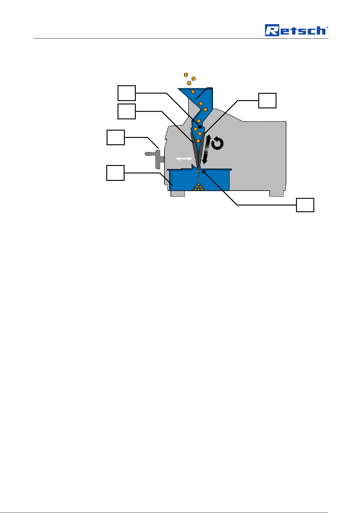
Fig. 1: Diagram of grinding
The grinding process in this machine takes place using pressure.
The grinding chamber (T) is funnel-shaped and narrows to the outlet opening (TA)
depending on the set gap width.
The gap width setting is infinitely adjustable.
The machine has a stationary crusher arm (RB) connected to the gap width
adjustment (D) and a mobile crusher arm (SB). Replaceable breaking jaws are
attached to both crusher arms, between which the grinding takes place by means
of pressure.
The eccentric movement of the actuated crusher arm (550...950/min) produces a
constant conveying of the grinding material until the final fineness has been
achieved that enables it to pass through the set gap (TA). It is then collected in a
removable collecting receptacle (E).
The convex shape of the replaceable breaking jaws made from different materials
ensures the best possible fine grinding and at the same time prevents material
compaction and a bridging effect.
12
Page 13
2BTechnical data
ES
BS A B
Pos: 5.8 /00 20 Übersc hriften/ 1.1 Übersc hriften/1.1 Überschr iften BDA/ 11 Schutz einricht ungen @ 0\mod_1226486316130_9.docx @ 3304 @ 2 @ 1
3.3 14BProtective equipment
Pos: 5.9 /00 05 RETSCH /0005 RET SCH Bedie nungsanl eitungen K apitelsa mmlungen/B B50/0005 T echnische Daten/00 65 BB50 Mo dul Schutz einricht ungen @ 5\mod_1345714560248_9.docx @ 34488 @ @ 1
Fig. 2: Protective devices
The machine is equipped with the following protective devices:
A: Splash-back protection
B: Fill hopper
BS: Switch for fill hopper
ES: Switch for drawer
Pos: 5.10 /0 020 Übersc hriften/1 .1 Übersc hriften/1. 1 Überschr iften BDA /11 Emmis ionen @ 0\ mod_1226487095021_9.docx @ 3310 @ 2 @ 1
3.4 15BEmissions
Pos: 5.11 /0 005 RETSC H/0005 R ETSCH Bedi enungsanl eitungen Kapitelsa mmlungen/B B50/0005 T echnisch e Daten/0020 BB50 Modul Emmisionen @ 5\mod_1345704766162_9.docx @ 34391 @ @ 1
Noise measurement
During grinding depending on the sample material:
– approx. 86,1 dB (A) without sample (speed 950 rpm)
Pos: 5.12 /0 020 Übers chriften/ 1.1 Übersc hriften/1. 1 Überschr iften BDA /11 Schut zart @ 0\mod_1226491839164_9.docx @ 3328 @ 2 @ 1
– approx. 88,6 dB (A) with marble break (speed 650 rpm)
3.5 16BDegree of protection
Pos: 5.13 /0 005 RETSC H/0005 R ETSCH Bedi enungsanl eitungen Kapitelsa mmlungen/B B50/0005 T echnisch e Daten/0 025 BB50 M odul Schu tzart @ 5\mod_1345704766746_9.docx @ 34402 @ @ 1
Pos: 5.14 /0 020 Übers chriften/ 1.1 Übersc hriften/1. 1 Überschr iften BDA /11 Motor drehzahl @ 1\mod_1241508280705_9.docx @ 8763 @ 2 @ 1
– IP20
3.6 17BMotor rotation speed
Pos: 5.15 /0 005 RETSC H/0005 R ETSCH Bedi enungsanl eitungen Kapitelsa mmlungen/B B50/0005 T echnisch e Daten/0 050 BB50 M odul Motor drehzahl @ 5\mod_1345704770208_9.docx @ 34457 @ @ 1
The motor speed is 550...950min
Pos: 5.16 /0 020 Übers chriften/ 1.1 Übersc hriften/1. 1 Überschr iften BDA /11 Aufna hmevolume n Retsch @ 1\mod_12415085339 45_9.docx @ 8777 @ 2 @ 1
550 - 600 - 650 - 700 - 750 - 800 - 850 - 900 - 950min
3.7 18BReceptacle volume
Pos: 5.17 /0 005 RETSC H/0005 R ETSCH Bedi enungsanl eitungen Kapitelsa mmlungen/B B50/0005 T echnisch e Daten/0 045 BB50 M odul Aufn ahmevolum e n @ 5\mod_1345704769680_9.docx @ 34446 @ @ 1
Pos: 5.18 /0 020 Übers chriften/ 1.1 Übersc hriften/1. 1 Überschr iften BDA /11 Aufga bekorngrö ße Retsch @ 3\mod_1302161462732_9.docx @ 24620 @ 2 @ 1
The collection volume is < 3 l.
Prevents sample ejection
Protects against reaching inside the machine
Checks position of the fill hopper and switches the
drive off
Checks drawer position
-1
and can be adjusted in increments of 50.
-1
3.8 19BFeed size
Pos: 5.19 /00 05 RETSCH/ 0005 RETS CH Bedie nungsanlei tungen Ka pitelsamml ungen/B B50/0005 T echnische D aten/00 55 BB50 Mod ul Aufga bekorngröß e @ 5\mod_1345705248780_9.docx @ 34468 @ @ 1
Pos: 5.20 /0 020 Übersc hriften/1 .1 Übersc hriften/1. 1 Überschr iften BDA /11 Nennl eistung @ 0\mod_1226491873164_9.docx @ 3334 @ 2 @ 1
3.9 20BRated power
Pos: 5.21 /0 005 RETSC H/0005 R ETSCH Bedi enungsanl eitungen Kapitelsa mmlungen/B B50/0005 T echnisch e Daten/0 030 BB50 M odul Nennl eistung @ 5\mod_1345704767288_9.docx @ 34413 @ @ 1
The maximum feed size is 40mm.
– 200-240 V: 1150W, 2 x 8A
13
Page 14

2BTechnical data
22.04.2014
Pos: 5.22 /0 020 Übers chriften/ 1.1 Übersc hriften/1. 1 Überschr iften BDA /11 Abmess ungen un d Gewicht R etsch @ 0\mod_1226492212173_9.docx @ 3352 @ 2 @ 1
3.10 21BDimensions and weight
Pos: 5.23 /0 005 RETSC H/0005 R ETSCH Bedi enungsanl eitungen Kapitelsa mmlungen/B B50/0005 T echnisch e Daten/0 035 BB50 M odul Abmes sungen un d Ge wi c ht @ 5\mod_1345704767776_9.d ocx @ 34424 @ @ 1
When closed:
Height: 463 mm
Width: 421 mm
Depth: 607 / 562 mm
Weight: approx. 76 kg
Pos: 5.24 /0 020 Übers chriften/ 1.1 Übersc hriften/1. 1 Überschr iften BDA /11 Erfor derliche S tandfläch e @ 0\mod_1226492678414_9.do cx @ 3364 @ 2 @ 1
Fig. 3: Dimensions
3.11 22BRequired floor space
Pos: 5.25 /0 005 RETSC H/0005 R ETSCH Bedi enungsanl eitungen Kapitelsa mmlungen/B B50/0005 T echnisch e Daten/0 040 BB50 M odul Erf orderliche Standfläche @ 5\mod_1345704768929_9.docx @ 34435 @ @ 1
607 mm (+ space for power plug) x 421 mm
- no safety distance necessary
Pos: 6 /000 5 RETSCH/0 005 RETSC H Bedien ungsanleit ungen Kapi telsamml ungen/------- Seiten umbruch ----------- @ 0\mod_1222344373758_0.docx @ 2386 @ @ 1
Space is required in front of the machine to pull the drawer out.
14
Page 15

Transport, scope of delivery, installation
NOTICE
Storage of packaging
NOTICE
Transport
NOTICE
Temperature fluctuations
NOTICE
Ambient temperature
Pos: 7.1 /00 20 Übersc hriften/ 1. Überschri ften/1 Ver packung, Transpor t und Aufst ellung @ 0 \mod_1226494451893 _9.docx @ 3380 @ 1 @ 1
4 Transport, scope of delivery, installation
Pos: 7.2 /00 20 Übersc hriften/ 1.1 Übersc hriften/1.1 Überschr iften BDA/ 11 Verpac kung @ 0\mod_1226495088973_9.docx @ 3392 @ 2 @ 1
4.1 23BPackaging
Pos: 7.3 /00 05 RETSCH /0099 RET SCH Standar d Kapit el/General Modul Ver packung @ 0\mod_1228984618355_9.docx @ 4892 @ @ 1
Pos: 7.4 /00 25 Warnhi nweise/H0 001 HINWE IS Aufbew ahrung der Verpacku ng @ 0\mod_1228918881595_9.docx @ 4753 @ @ 1
Pos: 7.5 /00 20 Übersc hriften/ 1.1 Übersc hriften/1.1 Überschr iften BDA/ 11 Transp ort @ 0\mod_1226495164391_9.docx @ 3398 @ 2 @ 1
4.2 24BTransport
Pos: 7.6 /00 25 Warnhinweise/H0017 HINWEIS Transport @ 0\mod_1228918883019_9.docx @ 4802 @ @ 1
The packaging has been adapted to the mode of transport. It complies with the
generally applicable packaging guidelines.
– In the event of a complaint or return, your warranty claims may be
endangered if the packaging is inadequate or the machine has not been
secured correctly.
• Please keep the packaging for the dura tion of the warranty period.
– Mechanical or electronic components may be damaged.
• The machine may not be knocked, shaken or thrown during
transport.
Pos: 7.7 /0020 Ü berschrif ten/1.1 Üb erschrift en/1.1 Üb erschrift en BDA/11 Temperatur schwank ungen @ 0\mod_1226495190738_9.docx @ 3404 @ 2 @ 1
4.3 25BTemperature fluctuations and condensed water
Pos: 7.8 /00 25 Warnhi nweise/H0 016 HINWE IS Temper aturschwa nkungen @ 0\mod_1233564121287_9 .docx @ 5570 @ @ 1
The machine may be subject to strong temperature fluctuations during transport
(e.g. aircraft transport)
– The resultant condensed water may damage electronic components.
• Protect the machine from condensed water.
Pos: 7.9 /00 20 Übersc hriften/ 1.1 Übersc hriften/1.1 Überschr iften BDA/ 11 Beding ungen für den Aufst ellort Rets ch @ 0\mod_1226497029322_9.docx @ 3428 @ 2 @ 1
4.4 26BConditions for the place of installation
Pos: 7.10 /0 005 RETSC H/0099 R ETSCH Sta ndard Kapi tel/General Modul U mgebungst emperatur 5°C - 40°C @ 0\mod_1228918538881_9.d ocx @ 4745 @ @ 1
Pos: 7.11 /0 025 Warnhi nweise/H 0021 HINW EIS Umgeb ungstemper atur 5°C bis 40°C @ 0\mod_1228918883441_9 .docx @ 4816 @ @ 1
Pos: 7.12 /0 005 RETSC H/0099 R ETSCH Sta ndard Kapi tel/General Modul L uftfeuchtig keit @ 0\ mod_1228918538693_9.docx @ 4738 @ @ 1
Ambient temperature: 5°C to 40°C
– Electronic and mechanical components may be damaged and the
performance data alter to an unknown extent.
• Do not exceed or fall below the permitted temperature range of the
machine (5°C to 40°C / ambient temperature).
Atmospheric humidity:
Maximum relative humidity 80% at temperatures up to 31°C, decreasing linearl y up
to 50% relative humidity at 40°C
15
Page 16

Transport, scope of delivery, installation
NOTICE
Atmospheric humidity
WARNING
NOTICE
NOTICE
Installation of the machine
1 2 3
4 5 6 7 8
9
10
11
12
14
13
Pos: 7.13 /0 025 Warnhi nweise/H 0011 HINW EIS Luftfe uchtigkeit @ 0\mod_1228918882628_9.docx @ 4788 @ @ 1
– Electronic and mechanical components may be damaged and the
performance data alter to an unknown extent.
• Do not exceed the admissible range for atmospheric humidity.
Pos: 7.14 /0020 Üb er s c hriften/1 .1 Ü b erschrifte n/1.1 Über sc hr i f t e n BD A / 1 1 El e k tr i s ch er A ns c hl uss @ 0\mod_1226565067445_9.do cx @ 3500 @ 2 @ 1
4.5 27BElectrical connection
Pos: 7.15 /0 005 RETSC H/0099 R ETSCH Sta ndard Kapi tel/General Modul El ektrischer Anschluss @ 0\mod_1228918538521_9.docx @ 4731 @ @ 1
When connecting the power cable to the mains supply, use an external fusethat
complies with the regulations applicable to the place of installation .
• Please check the type plate for details on the necessary voltage and
frequency for the device.
• Make sure the levels agree with the existing mains power supply.
• Use the supplied connection cable to connect the device to the mains power
Pos: 7.16 /0025 War nhinweis e/H 0008 HINW EI S Elektrisc h er Ans chluss @ 0\ mod_1228918882424_9.docx @ 4781 @ @ 1
supply.
Electrical connection
– Mechanical or electronic components may be damaged.
• Please observe the information on the type plate.
Pos: 7.17 /0 025 Warnhi nweise/H 0002 HINW EIS Aufst ellung Zug ang Gerät esteckdose @ 0\mod_1233836960983_9.docx @ 5820 @ @ 1
– It must be possible to disconnet the machine from the mains at any time.
• Install the machine such that the connection for the mains cable is
easily accessible.
Pos: 7.18.1 /0020 Über schriften /1.1 Über schriften/ 1.1 Übers chriften B DA/11 Typ enschild B eschreib ung @ 3\mod_1280933953941_9.docx @ 22302 @ 2 @ 1
4.6 28BType plate description
Pos: 7.18.2 /0005 RET SCH/0099 R ETSCH S tandard Ka pitel/Gen eral Modul Typenschi ld @ 3\mod_1280931092443_9.docx @ 22278 @ @ 1
16
Fig. 4: Type plate lettering
1 Device designation
Page 17

Transport, scope of delivery, installation
B R E P G
2 Year of production
3 Part number
4 Serial number
5 Manufacturer’s address
6 CE marking
7 Disposal label
8 Bar code
9 Power version
10 Mains frequency
11 Capacity
12 Amperage
13 Number of fuses
14 Fuse type and fuse strength
In the case of questions please provide the device designation (1) or the part
Pos: 7.19 /0 020 Übers chriften/ 1.1 Übersc hriften/1. 1 Überschr iften BDA /11 Trans porthilfe entferne n @ 0\mod_1229076673566_9.docx @ 5020 @ 2 @ 1
number (3) and the serial number (4) of the device.
4.7 29BRemoving Transport Safeguards
Pos: 7.20 /0005 RETSCH/0005 RETSCH Bedienungsanleitungen Kapi telsamml ungen/BB5 0/0006 Ver packung, T ransport und Aufs tellung/00 05 BB50 Mo dul Trans porthilfe entfernen @ 5\mod_1345721568835_9.docx @ 34508 @ @ 1
Fig. 5: Carrying the machine - preparation
• Before installing the carry support, remove the hopper (B) and the
grinding room cover (P).
(see chapter Cleaning removing the fill hopper / removing the splash-back
protection)
• Before carrying the machine, remove the bolt (G), the crusher arm
(R) and the drawer (E) to make the machine lighter.
(see chapter Servicing replacing the breaking jaws)
17
Page 18

Transport, scope of delivery, installation
TS
TB
WS
W
22.04.2014
Fig. 6: Mounting the transport aid
Pos: 7.21 /0 020 Übers chriften/ 1.1 Übersc hriften/1. 1 Überschr iften BDA /11 Trans portsicher ung entf ernen @ 0\mod_1227530921618_9.docx @ 3980 @ 2 @ 1
• Fix the two transport aids (W) using screws (WS) to the machine.
4.8 30BRemoving the transport safeguard
Pos: 7.22 /0 005 RETSC H/0005 R ETSCH Bedi enungsanl eitungen Kapitelsa mmlungen/B B50/0006 Verpacku ng, Transp ort und A ufstellung/ 0010 BB50 Modul Tra nsportsic herung ent fernen @ 5\mod_1357546736532_9.docx @ 37050 @ @ 1
Fig. 7: Removing the transport lock
The machine is secured by steel plates on both sides.
• Remove the two screws (TS).
Pos: 7.23 /0 020 Übers chriften/ 1.1 Übersc hriften/1. 1 Überschr iften BDA /11 Aufst ellen des G erätes Re tsch @ 0\ mod_1226498849756_9.docx @ 3464 @ 2 @ 1
• Pull the transport lock (TB) out sideways.
4.9 31BInstallation of the machine
Pos: 7.24 /0 005 RETSC H/0099 R ETSCH Sta ndard Kapi tel/General Modul A ufstellung shöhe @ 0 \mod_1228918538349_9.docx @ 4724 @ @ 1
Pos: 8 /000 5 RETSCH/0 005 RETSC H Bedien ungsanleit ungen Kapi telsamml ungen/------- Seiten umbruch ----------- @ 0\mod_1222344373758_0.docx @ 2386 @ @ 1
18
Installation height: maximum 2000 m above sea level
Page 19

Operating the machine
D E B A C G F
H,K,L
M N O
Pos: 9.1 /00 20 Übersc hriften/ 1. Überschri ften/1 Be dienung de s Gerätes @ 0\mod_1226565880211_9.docx @ 3519 @ 1 @ 1
5 Operating the machine
Pos: 9.2 /00 20 Übersc hriften/ 1. 1 Üb er s c hr i f t en / 1 .1 Überschri ft en BDA/11 Ansi c hten des Ger ät es Retsch @ 0\mod_1228990581782_9.docx @ 4966 @ 2 @ 1
5.1 32BViews of the Instrument
Pos: 9.3 /00 05 RETSCH /0005 RET SCH Bedie nungsanl eitungen K apitelsa mmlungen/B B50/0007 Bedienung/000 5 BB50 Modul Ansichten des Gerätes @ 5\mod_1345555394077_9.docx @ 34280 @ @ 1
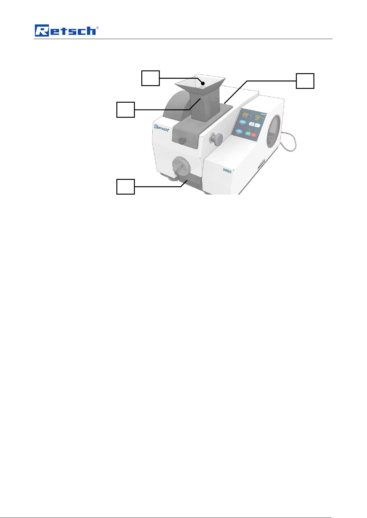
Fig. 8: Front view
Fig. 9: Rear view
19
Page 20

Operating the machine
P R G
22.04.2014
S E D
F
Fig. 10: Machine partially open
Pos: 9.4 /00 05 RETSCH /0005 RET SCH Bedie nungsanl eitungen K apitelsa mmlungen/------- Seit enumbruc h ----------- @ 0\mod_1222344373758_0.docx @ 2386 @ @ 1
20
Page 21

Operating the machine
22.04.2014
Pos: 9.5 /00 20 Übersc hriften/ 1.1 Übersc hriften/1.1 Überschr iften BDA/ 11 Übersi chtstabell e der Ger äteteile @ 0\mod_1228990616846_9.docx @ 4972 @ 2 @ 1
5.2 33BOverview table of the parts of the device
Pos: 9.6 /00 05 RETSCH /0005 RET SCH Bedie nungsanl eitungen K apitelsa mmlungen/B B50/0007 B edienung /0006 BB50 M odul Üb ersichtst abelle Ger äteteile @ 5\mod_1345618254846_9.docx @ 34290 @ @ 1
Element Description Function
A
B
C
D
E
F
G
H
K
L
M
N
Splash-back protection Prevents sample ejection
Fill hopper Receives the grinding material
Release handle Releases the folding hopper
Hand wheel with folding handle Setting the gap width
Drawer Receives the ground sample material
Operator panel and display (see below)
Bolt for front crusher arm Holds the front crusher arm
On and off switch Disconnects the controller from or connects it to the
mains.
Machine fuse Overload protection. Disconnects the motor from
the mains in the event of overload.
Mains connection Connection for power supply
Warning sign Caution electric shock! Housing may only be
opened by trained staff. Pull the mains plug before
servicing!
Instruction to read the operating
manual
Read the operating manual before putting into
operation!
O
P
R
S
Pos: 9.7 /00 05 RETSCH /0005 RET SCH Bedie nungsanl eitungen K apitelsa mmlungen/------- Seit enumbruc h ----------- @ 0\mod_1222344373758_0.docx @ 2386 @ @ 1
Type plate Machine designation
Grinding chamber cover Dirt protection, dust protection
Front crusher arm (shown partially
Support for front breaking jaw
pulled out)
Rear crusher arm (hidden) Support for rear breaking jaw
21
Page 22

Operating the machine
F1
F3
F5
F2
F4
F6
22.04.2014
Pos: 9.8 /00 20 Übersc hriften/ 1.1 Übersc hriften/1.1 Überschr iften BDA/ 11 Bedien elemente und Anzeig en Retsch @ 0\mod_1226566557086_9.docx @ 3543 @ 2 @ 1
5.3 34BOperating elements and displays
Pos: 9.9 /00 05 RETSCH /0005 RET SCH Bedie nungsanl eitungen K apitelsa mmlungen/BB50/0007 Bedienung/0007 BB50 Modul Ansichten des Bedienfeldes @ 5\mod_1345621570910_9.docx @ 34300 @ @ 1
Fig. 11: View of the operator panel and displays
Pos: 9.10 /0 020 Übers chriften/ 1.1 Übersc hriften/1. 1 Überschr iften BDA /11 Übersi chtstabel le der Be dieneleme nte und der Anzeige @ 0\mod_1228990697273_9. docx @ 4978 @ 2 @ 1
5.4 35BOverview Table of the Operating Elements and the Display
Pos: 9.11 /0 005 RETSC H/0005 R ETSCH Bedi enungsanl eitungen Kapitelsa mmlungen/B B50/0007 Bedienung /0008 BB5 0 Modul Ü bersichtst abelle Be dienfeld @ 5\mod_1345622654959_9.docx @ 34310 @ @ 1
Element Description Function
F1
F2
F3
F4 + and - buttons
F5
F6
Pos: 9.12 /0 005 RETSC H/0005 R ETSCH Bedi enungsanl eitungen Kapitelsa mmlungen/------- Seitenumbruch ----------- @ 0\mod_1222344373758_0.docx @ 2386 @ @ 1
Display of the gap width in m m Displays the gap width
Display of the speed Number of crushing jaw lifts per minute
Gap width zeroing Zero value setting on crushing jaw contact
Setting the crushing jaw speed
Reverse running Dislodging or loosening a sample blockage
START and STOP buttons Starting and stopping the motor
22
Page 23

Operating the machine
D
H
Pos: 9.13 /0 020 Übers chriften/ 1.1 Übersc hriften/1. 1 Überschr iften BDA /11 Ein- / A usschalt en @ 0\mod_1229416527496_9.docx @ 5058 @ 2 @ 1
5.5 36BSwitching On and Off
Pos: 9.14 /0005 RETSCH/0005 RETSCH Bedienungsanleitungen Kapi t elsammlung en/BB50/ 0007 Bedi en ung / 0009 BB50 M od ul Ein Aus Schal t en @ 5\mod_1345800934785_9.docx @ 34520 @ @ 1
Fig. 12: Switching on / off
– The main switch (H) can be found on the back of the machine.
• Switch the main switch (H) on.
– The displays for the gap width and the speed light up.
Pos: 9.15 /0 020 Übers chriften/ 1.1 Übersc hriften/1. 1 Überschr iften BDA /11 Spalt weite auf N ullstell ung setzen @ 5\mod_1345445748972_9.docx @ 34160 @ 2 @ 1
– The machine is ready to use.
5.6 37BSetting the gap width to zero position
Pos: 9.16 /0 005 RETSC H/0005 R ETSCH Bedi enungsanl eitungen Kapitelsa mmlungen/B B50/0007 Bedienung /0011 BB5 0 Modul Sp altweite N ullstell ung @ 5\ mod_1346050929641_9.docx @ 34540 @ @ 1
NOTICE
The gap width may only be adjusted during idl in g witho ut grindi ng m ater ia l.
Grinding material may be neither in the crushing chamber nor in the fill hopper.
The breaking jaws may not have any contact so as to prevent a blockage and the
associated potential damage to the breaking jaws.
Preparation:
• Switch the machine on at the main switch.
• Remove all grinding material from the fill hopper and crushing chamber.
When aligning the gap width, the breaking jaws must not demonstrate any contact
to each other when beginning the adjustment.
• Before starting the machine, twist the hand wheel (D)
2 revolutions in an anti-clockwise direction.
Fig. 13: Aligning the gap width
• Start the machine by pressing the START button (F6)
• Turn the hand wheel (D) clockwise until a clicking acoustically signals
the contact of the crusher arms.
• Press the button (F3).
23
Page 24

Operating the machine
sw D F3
Fig. 14:
The display (F1) shows 00.0. The current gap width and the display therefore
match.
The wear of the breaking jaws is not recorded by the gap width measurement. For
this reason the alignment of the gap width should be performed regularly in order
to guarantee matching between the information in the display and actual gap width.
The greater the load on the BB 50 and the harder and more abrasive the grinding
material, the more frequently a zero point alignment to compensate for wear is
required.
Pos: 9.17 /0 020 Übers chriften/ 1.1 Übersc hriften/1. 1 Überschr iften BDA /11 Spalt weite eins tellen @ 5\mod_1345445670122_9.docx @ 34150 @ 2 @ 1
The reading in the display will otherwise not correspond to the actual gap width.
5.7 38BSetting the gap width
Pos: 9.18 /0 005 RETSC H/0005 R ETSCH Bedi enungsanl eitungen Kapitelsa mmlungen/B B50/0007 Bedienung /0010 BB5 0 Modul Sp altweiten einstellung @ 5\mod_1346050883310_ 9.docx @ 34530 @ @ 1
NOTICE
Before starting the machine, do not put any grinding material in the grinding
chamber or fill hopper. This can lead to a blockage and cause damage to
mechanical components.
• You can reduce the gap width (sw) with a twist of the hand wheel (D)
in a clockwise direction.
• You can increase the gap widt h (sw) with a twist of the hand wheel (D)
in an anti-clockwise direction
24
Fig. 15: Gap width
Page 25

Operating the machine
F5
F2
bb
F4
Pos: 9.19 /0 020 Übers chriften/ 1.1 Übersc hriften/1. 1 Überschr iften BDA /11 Rever se - Verma hlung @ 3\ mod_1279717723614_9.docx @ 21493 @ 2 @ 1
5.8 39BReverse grinding
Pos: 9.20 /0 005 RETSC H/0005 R ETSCH Bedi enungsanl eitungen Kapitelsa mmlungen/B B50/0007 Bedienung /0012 BB5 0 Modul R everse-Ver mahlung @ 5\mod_1346050964001_9.docx @ 34551 @ @ 1
Fig. 16: Bridging effect in the grinding chamber
Fig. 17: Reverse button
Using the reverse function you can release grinding material in the event of a
blockage in the machine or of bridging.
• Stop grinding.
• Press the reverse button (F5).
The machine will run backwards as long as you keep t he reverse button pressed,
Pos: 9.21 /0 020 Übers chriften/ 1.1 Übersc hriften/1. 1 Überschr iften BDA /11 Drehz ahl einstel len @ 1\mod_1250081022665_9.docx @ 13816 @ 2 @ 1
and wedged material will be dislodged.
5.9 40BSetting the Speed
Pos: 9.22 /0 005 RETSC H/0005 R ETSCH Bedi enungsanlei tungen Kapitelsam mlungen/B B50/0007 Bedienung/ 0013 BB5 0 Modul Dr ehzahl ei nstellen @ 5\mod_1346050969438_9.docx @ 34650 @ @ 1
Fig. 18: Setting the speed
• Switch the machine on at the main switch.
The selectable grinding speed lies bet ween 550 and 950 revolutions per minute
Briefly press button (F4 +) to increase the speed in increments of 50.
•
Briefly press button (F4 -) to decrease the speed in increments of 50.
•
When pressed for longer the speed levels are run through quickly. The display
shows the last value which is updated when the button is released.
25
Page 26

Operating the machine
F1
F6
D
Pos: 9.23 /0 020 Übers chriften/ 1.1 Übersc hriften/1. 1 Überschr iften BDA /11 Mahlv organg st arten @ 0\mod_1227185008190_9.docx @ 3861 @ 2 @ 1
5.10 41BStarting the grinding process
Pos: 9.24 /0 005 RETSC H/0005 R ETSCH Bedi enungsanl eitungen Kapitelsa mmlungen/B B50/0007 Bedienung /0014 BB5 0 Modul M ahl vorgang st ar te n @ 5\ mod_1346050969994_9.docx @ 34661 @ @ 1
Fig. 19: Start grinding
• Press the START button (F6).
The green LED above the START button lights up. The machine starts up.
Fig. 20: Gap width
• Adjust the gap width as required using the hand wheel (D).
You can reduce the gap width (sw) with a twist of the hand wheel (D)
in a clockwise direction.
You can increase the gap widt h (sw) with a twist of the hand wheel (D)
in an anti-clockwise direction.
The values on the display (F1) specify the gap width in mm. The display accuracy
is ± 0.1mm.
The end of the grinding process may be recognised acoustically by a change in
Pos: 9.25 /0 020 Übers chriften/ 1.1 Übersc hriften/1. 1 Überschr iften BDA /11 Mahlv organg st oppen @ 0\mod_1226909892231_9.docx @ 3643 @ 2 @ 1
sound and the machine can be switched off.
5.11 42BStopping the grinding proce ss
Pos: 9.26 /0 005 RETSC H/0005 R ETSCH Bedi e nungsanlei tungen Kapi t elsammlung en/BB50/ 0007 Bedi en ung / 0015 BB50 M od ul M ahl vorgang st op pe n @ 5\ mod_1346050970540_9.docx @ 34672 @ @ 1
NOTICE
Only interrupt the grinding if no more grinding material is in the fill hopper or
crushing chamber.
Mechanical components might be damaged by a blockage when starting up.
• Press the STOP button (F6).
26
Page 27

Safety functions and fault display
The red LED above the STOP button lights up and the green LED above the
Pos: 9.27 /0 020 Übers chriften/ 1.1 Übersc hriften/1. 1 Überschri f te n BDA/11 Pro be n behälter @ 5\ mod_1345454254753_9.docx @ 34220 @ 2 @ 1
START button goes out. The machine stops.
5.12 43BSample receptacle
Pos: 9.28 /0 005 RETSC H/0005 R ETSCH Bedi enungsanl eitungen Kapitelsa mmlungen/B B50/0007 Bedienung /0016 BB5 0 Modul Pr obenbehäl ter @ 5\mod_1346050971062_9.docx @ 34683 @ @ 1
Fig. 21: Sample receptacle
Pos: 11.1 /0020 Überschriften/1. Überschriften/1 Sicherheitsfunktionen und Fehleranzeige @ 0\mod_1226908695377_9.docx @ 3594 @ 1 @ 1
6 Safety functions and fault display
Pos: 11.2 /0 020 Übers chriften/ 1.1 Übersc hriften/1. 1 Überschr iften BDA /11 Fehler meldunge n @ 0\mod_1222344568006_9.docx @ 2435 @ 2 @ 1
6.1 44BFault messages
Pos: 11.3 /0005 RETSCH/0005 R ET SC H Bedienung sa nleitunge n Kapitelsa m ml ungen/BB 5 0/ 0 009 Sicherh ei ts funktio ne n un d F e hl er anzeige /0 00 8 B B50 Modul Fe hl er meldunge n @ 5\ mod_1346844648119_9.docx @ 34851 @ @ 1
Error code
DESCRIPTION
E 10 DRIVE OVERLOADED E 10
E 22 ERROR KEYPAD E 22 Switch machine off and back on.
E 26
ERROR FREQUENCY
CONVERTER
E 50 ERROR SAFETY CIRCUIT E 50
E 80 ERROR INTERFACE E80
Display
gap width
Display speed
E 26
Switch machine off and back on. Where
necessary wait 10 minutes
Frequency converter is faulty. Service is
required
Safety circuit is faulty. Service is
required
Communication fault in controller
Service is required
H 41 CLOSE GRINDING CHAMBER H41 Close hopper/drawer and press STOP
H 43 WEAR LIMIT REACHED H 43 Replace breaking jaws
H 44 PLEA SE C A LIBRATE PLS CAL Calibrate gap width
"Gap width" und "Speed" displays flash 88.8 888
Close hopper and drawer;
restart the machine
27
Page 28

Cleaning, wear and service
WARNING
Risk of a fatal electric shock
C
B
B
Pos: 12.1 /0 020 Übers chriften/ 1. Übersc hriften/1 R einigung , Verschleiß und Wart ung @ 0\mod_1228989974062_9.docx @ 4948 @ 1 @ 1
7 Cleaning, wear and service
Pos: 12.2 /0020 Überschriften/1.1 Überschrifte n/1.1 Über schrifte n BDA/11 R einigung @ 0\mod_1226909670239_9.docx @ 3607 @ 2 @ 1
7.1 45BCleaning
Pos: 12.3 /0025 War nhinweis e/ W0003 WARN U N G R ei nigung Str om s t oß neu @ 1\mod_1236239978437_9.docx @ 7686 @ @ 1
- An electric shock can cause injuries in the form of burns and cardiac
arrhythmia, respiratory arrest or cardiac arrest.
• Do not clean the blender under running water. Use only a cloth dampened
with water.
• Disconnect the power supply plug before cleaning the blender.
Pos: 12.4 /0 005 RETSC H/0005 R ETSCH Bedi enungsanl eitungen Kapitelsa mmlungen/B B50/0010 R einigung Wartung V erschleiß /0004 BB5 0 Modul R einigung @ 5\mod_1346079086585_9.docx @ 34787 @ @ 1
Pos: 12.5 /0020 Überschriften/1.1.1. Überschr iften/11 1 Einfülltri chter entf ernen @ 5 \mod_1345454411097_9.docx @ 34240 @ 3 @ 1
7.1.1 49BRemoving the feed hopper
Pos: 12.6 /0005 RETSCH/0005 RETSCH Bedienungsanleitungen Kapitelsammlungen/BB50/0010 Rei nig ung Wartu ng Ver s c hleiß/000 6 B B50 Modul Einfül l tr i c hter entfer nen @ 5\mod_1346078728003_9.docx @ 34710 @ @ 1
Fig. 1: Opening the hopper flap
• Pull the release handle (C) and fold back the fill hopper (B).
Fig. 2: Remove the hopper flap
• Pull off the fill hopper (B) against the resistance of the locks.
28
Page 29

Cleaning, wear and service
CAUTION
V0072
Risk of injury to eyes and skin
A
P
As
Pos: 12.7 /0 020 Übers chriften/ 1.1.1. Über schriften /111 Rüc kspritzschu tz entfer nen @ 5\mod_1345454468347_9.docx @ 34250 @ 3 @ 1
7.1.2 50BRemoving the splash-back protection
Pos: 12.8 /0 025 Warnhi nweise/V 0072 VORS ICHT Aug en Verletzu ng Heraus geschleu dertes Mahl gut Rücks pritzschut z @ 5\mod_1346142066348_9.docx @ 34811 @ @ 1
Ejected sample material
– Sample material can be ejected from the machine if the splash-
back protection is missing.
• Never operate the machine without the splash-back
protection.
Pos: 12.9 /0005 RETSCH/0005 RETSCH Bedienungsanleitungen Kapi telsamml ungen/BB5 0/0010 Rei nigung W artung Vers chleiß/0 007 BB50 M odul Rüc kspritzsch utz entfern en @ 5\mod_1346078784486_9.docx @ 34721 @ @ 1
Fig. 22: Removing the splash-back protection
• Unscrew both screws (As).
• Remove the splash-back protection for cleaning (A).
Pos: 12.10 / 0020 Über schriften/ 1.1.1. Üb erschrifte n/111 Ma hlraumkla ppe entfern en @ 5\mod_1345454523628_9.docx @ 34260 @ 3 @ 1
7.1.3 51BRemoving the grinding chamber cover
Pos: 12.11 / 0005 RET SCH/0005 R ETSCH Bedi enungsa nleitungen Kapitels ammlungen/ BB50/001 0 Reinigu ng Wartung Verschlei ß/0008 BB 50 Modul Mahlraumklappe entf ernen @ 5\mod_1346078785220_9.docx @ 34732 @ @ 1
• Secure the splash-back protection to the fill hopper again after cleaning.
1.
Pos: 12.12 / 0020 Über schriften/ 1.1 Übers chriften/ 1.1 Übersc hriften BD A/11 Wart ung @ 0\mod_1226909694066_9.docx @ 3613 @ 2 @ 1
7.2 46BService
Pos: 12.13 / 0005 RET SCH/0005 R ETSCH Bedi enungsa nleitungen Kapitels ammlungen/ BB50/001 0 Reinigu ng Wartung Verschlei ß/0012 BB 50 Modul Wartung @ 5\mod_1346078787835_9.docx @ 34776 @ @ 1
Pos: 12.14 / 0020 Über schriften/ 1.1.1. Üb erschrifte n/111 Bre chbacken austausch en @ 5\mod_1345454370810_9.docx @ 34230 @ 3 @ 1
7.2.1 52BReplacing the breaking jaws
Pos: 12.15 / 0005 RET SCH/0005 R ETSCH Bedi enungsa nleitungen Kapitels ammlungen/ BB50/001 0 Reinigu ng Wartung Verschlei ß/0009 BB 50 Modul Br echback en vorn aus tauschen @ 5\mod_1346078785877_9.docx @ 34 74 3 @ 3 @ 1
ntv
Fig. 23: Removing the grinding chamber cover
• Remove the grinding chamber cover (P) as shown in the above figure.
This machine requires no servicing. When correctly used no adjustment work is
required.
29
Page 30

Cleaning, wear and service
G
Gp
G
G
Rn
ZV
ZB
7.2.2
53BReplacing the front breaking jaw
NOTICE
Zircon breaking jaws (ZB) are bonded across the entire surface (ZV).
• Have the zircon breaking jaws replaced by an authorised service
technician.
Fig. 24: Bonding the zircon breaking jaws
• Empty the grinding chamber before replacing the breaking jaws.
• Set the gap width to between 2 and 10 mm.
Fig. 25: Removing the bolt
• Twist the grip of the bolt (G) until the locking pin (Gp) can be seen in the top opening of the guide.
Fig. 26: Using the (bolt) removal tool
30
Page 31

Cleaning, wear and service
Rn
G
RB
R
RS
RH
• Pull the bolt (G) out of the guide.
• Place the bolt (G) in the removal groove (Rn) of the front crusher arm.
Fig. 27: Removing the break ing jaw
• Pull the crusher arm upwards out of the machine.
Fig. 28: Replacing the breaking jaw
• Unscrew the two screws (RS).
• Remove the retaining plate (RH)
• Replace the breaking jaw (RB).
31
Page 32

Cleaning, wear and service
RS
RH
RB
RS
RL
Fig. 29: Screw securing adhesive
• Use two new screws (RS) for installation or secure
Pos: 12.16 / 0005 RET SCH/0005 R ETSCH Bedi enungsa nleitungen Kapitels ammlungen/ BB50/001 0 Reinigu ng Wartung Verschlei ß/0010 BB 50 Modul Br echback en hinten a ustausche n @ 5\mod_1346078786485_9.docx @ 34754 @ @ 1
both screws with liquid screw securing adhesive (RL).
Fig. 30: Replacing the rear breaking jaw
The rear breaking jaw is replaced directly in the machine. The rear crusher arm
remains in the machine in the process.
• Unscrew the two screws (RS).
• Remove the retaining plate (RH)
• Replace the breaking jaw (RB).
32
Page 33

Pos: 12.17 / 0020 Über schriften/ 1.1 Übers chriften/ 1.1 Übersc hriften BD A/11 Versc hleiß @ 0\ mod_1226909713106_9.docx @ 3619 @ 2 @ 1
F1
F2
RS
RL
Cleaning, wear and service
Fig. 31: Screw securing adhesive
• Use two new screws (RS) for installation or secure both screws with liquid
screw securing adhesive (RL).
7.3 47BWear
Pos: 12.18 / 0005 RET SCH/0005 R ETSCH Bedi enungsa nleitungen Kapitels ammlungen/ BB50/001 0 Reinigu ng Wartung Verschlei ß / 00 1 1 BB50 Modul Ver sc hleiß @ 5\mod_1346078787141_9.docx @ 34765 @ 34 @ 1
7.3.1 54BResetting the wear alert
NOTICE
After replacing the breaking jaws, the wear warning should be reset.
Fig. 32: Wear alert
The wear alert (F42) appears when the breaking jaws are worn.
The currently set gap width flashes in the gap width (F1) display and the error
code H43 is displayed in the speed (F2) display.
• Press the STOP button.
7.3.1.1 Setting the operating time until the calibration alert is displayed
You can set the time until the calibration reminder appears. The time until the next
calibration depends on the sample material and application.
• Press the STOP button (F6).
33
Page 34

Cleaning, wear and service
F6
22.04.2014
• Simultaneously press the buttons RESET+START for 2 seconds.
The currently set operating time until calibration flashes in the gap width (F1)
display (default: 50h) and h is displayed in the speed (F2) display.
Briefly press the button (F4 +) to increase the operating time in increments of
•
10.
Briefly press the button (F4 -) to decrease the operating time in increments
•
of 10.
Pos: 13.1 /0005 RETSCH/0005 RETSCH Bedienungsanleitungen Kapitelsammlungen/------- Seitenumbruch ----------- @ 0\mod_122234437375 8_0.docx @ 2386 @ @ 1
Fig. 33: Operating time until the calibration alert
34
Page 35

Pos: 13.2 /0005 RETSCH/0015 RETSCH Reparat ur- und Mon tageanleit ungen/00 000 Übersc hriften/1. Übersc hriften/1 E ntsorgung @ 0\mod_1234258746831_9.docx @ 6173 @ 1 @ 1
8 Disposal
Pos: 13.3 /0 010 RETSC H Standar d KapitelG eneral Mo dul Entsor gung @ 0\mod_1234269404935_9.docx @ 6180 @ @ 1
Disposal
Please observe the respective statutory requirements with respect to disposal.
Information on disposal of electrical and electronic machines in the European
Community.
Within the European Community the disposal of electrically operated devices is
regulated by national provisions that are based on the EU Directive 2002/96/EC on
Waste Electrical and Electronic Equipment (WEEE).
Accordingly, all machines supplied after 13.08.2005 in the business-to-business
area to which this product is classified, may no longer be disposed of with
municipal or household waste. To document this they have the following label:
=== Ende der Liste für Textmar ke Inhalt == =
Fig. 34: Disposal label
Since the disposal regulations within the EU may differ from country to country we
would request you to consult your supplier.
35
Page 36

9 8BIndex – Verzeichnis
8
88.8/888 27
A
Aligning the gap width 23
Ambient temperature 15
Amperage 17
Atmospheric humidity 15
B
Bar code 17
Bonding 30
Bridging effect 25
C
CAL 27
Calibration alert 34
Calibration reminder 33
Capacity 17
Carrying the machine - preparation 17
CE marking 17
Changes 6
Cleaning 28
Cleaning, wear and service 28
collection volume 13
Conditions for the place of installation 15
Confirmation 10
Connection cable 16
Copyright 6
D
Degree of protection 13
Device designation 16
Dimensions 14
Dimensions and weight 14
Disposal 35
Disposal label 17
Disposal label 35
E
E10; E22; E26; E50 27
Electrical connection 16
Emissions 13
Error code 27
Explanations of the safety warnings 7
External fuse 16
F
Fault messages 27
feed size 13
Feed size 13
Front view 19
funnel-shaped 12
Fuse strength 17
Fuse type 17
G
Gap width 24
General safety instructions 8
Grinding process 12
Grinding speed 25
H
H41; H43 27
I
Installation height 18
Installation of the machine 18
IP20 13
M
Mains frequency 17
Manufacturer’s address 17
Maximum feed size 13
Maximum relative humidity 15
Moderate or mild injury 7
Motor rotation speed 13
Motor speed 13
Mounting the transport aid 18
N
Noise measurement 13
Notes on the Operating Manual 6
Number of fuses 17
O
Operating elements and displays 22
Operating the machine 19
Operating time until the calibration alert 33
Overview Table of the Operating Elements and
the Display 22
Overview table of the parts of the device 21
P
Packaging 15
Part number 17
PLS 27
Power version 17
property damage 7
Protective devices 13
Protective equipment 13
R
Rated power 13
Rear view 19
Receptacle volume 13
Regulations for the place of installation 16
Removing the feed hopper 28
Removing the grinding chamber cover 29
Removing the splash-back protection 29
Removing the splash-back protection 29
36
Page 37

Removing the transport lock 18
Removing the transport safeguard 18
Removing Transport Safeguards 17
Repairs 9
Replacing the breaking jaws 29
Required floor space 14
Reverse 25
Reverse grinding 25
S
Safety functions and fault display 27
Safety warnings 7
Sample receptacle 27
Screw securing adhesive 33
Serial number 17
serious injury 7
Service 29
Service Address 9
Setting the gap width 24
Setting the Speed 25
Starting the grinding process 26
Stopping the grinding process 26
Switching On and Off 23
T
Target group 8
Technical data 11
Temperature fluctuation and condensed water 15
Transport 15
Transport, scope of delivery, installation 15
Type plate 16
type plate description 16
Type plate lettering 16
U
Use of the machine for the intended purpose 11
V
Views of the Instrument 19
W
Wear 33
Wear alert 33
Working instructions 12
Y
Year of production 17
Z
Zero position 23
Zircon breaking jaws 30
37
Page 38

Authorized person for the compilation of technical documents:
Certificate of CE-Conformity according to:
LABORATORY J AW CRUSHER
CERTIFICATE OF CE-CONFORMITY
BB50
EC Mechanical Engineering Directive 2006/42/EC
Applied harmonized standards, in particular:
DIN EN ISO 12100 Security of machines
EC Directive Electromagnetic Compatibility 2004/108/EC
Applied standards, in particular:
EN 55011:2009 + A1:2010, Group 1, Class B Radio Interference - limits and measurement methods
EN 61000-3-3:2008
EN 61326-1:2006 incl. IEC 61000-4-2 to …4-6 and …4-11
Additional applied standards, in p ar ticular
DIN EN 61010-1:2011-07 Safety prescriptions concerning measuring-, operating-, controlling- and
laboratory equipment
Translation
J. Bunke (technical documentation)
The following records are held by Rets ch GmbH in the form of Technical Documentation:
Detailed records of engin eering dev elopm ent, constru ction plans, s tudy (anal ysis) of the measur es required f or
conformity assurance, analysis of the residual risks involved and operating instructions in due form according to
the approved regulations for preparation of user information data.
The CE-conformity of the Retsch Laboratory Jaw Crusher is assured herewith.
In case of a modification to the machine not previously agreed with us as well as the use of not
licensed spare parts and accessories this certificate will lose its validity.
Retsch GmbH Haan, january 2013
Dr. –Ing. Frank Janetta
Manager Development
FB-EW-805-079 (E) Änderungsstand A 01/2013
Retsch GmbH • Retsch-Allee 1- 5 • 42781 Haan • Germany • www.retsch.com
Page 39

Page 40

Page 41

Copyright
® Copyright by
Retsch GmbH
Haan, Retsch-Allee 1-5
D-42781 Haan
Federal Republic of Germany
 Loading...