

Page 1
Manual
Air Jet Sieving Machine AS200jet
Translation
© Retsch GmbH, 42781 Haan, Retsch-Allee 1-5, Germany 18.09.2014 0011
Page 2

Copyright
© Copyright by
Retsch GmbH
Haan, Retsch-Allee 1-5
D-42781 Haan
Federal Republic of Germany
2
Page 3

3
Page 4

1 Notes on the Operating Manual ............................................................................................................ 6
1.1 Explanations of the safety warnings .................................................................................................. 7
1.2 General safety instructions ................................................................................................................ 8
1.3 Repairs ............................................................................................................................................... 9
2 Confirmation ......................................................................................................................................... 10
3 Technical data ....................................................................................................................................... 11
3.1 Use of the machine for the intended purpose.................................................................................. 11
3.2 Emissions......................................................................................................................................... 12
3.3 Maximum Load ................................................................................................................................ 13
3.4 Degree of protection ........................................................................................................................ 13
3.5 Dimensions and weight .................................................................................................................... 13
3.6 Required floor space ........................................................................................................................ 13
3.7 Rated power .................................................................................................................................... 13
3.8 Type plate description ...................................................................................................................... 14
4 Transport, scope of delivery, installation .......................................................................................... 15
4.1 Packaging ........................................................................................................................................ 15
4.2 Transport.......................................................................................................................................... 15
4.3 Temperature fluctuations and condensed water ............................................................................. 15
4.4 Conditions for the place of installation ............................................................................................. 15
4.5 Installation of the machine ............................................................................................................... 15
4.6 Electrical connection ........................................................................................................................ 16
5 Operating the machine ........................................................................................................................ 18
5.1 Views of the Instrument ................................................................................................................... 18
5.2 Operating elements and displays .................................................................................................... 20
5.3 Overview table of the parts of the device ........................................................................................ 21
5.4 Working procedure .......................................................................................................................... 22
5.5 Switching On and Off ....................................................................................................................... 22
5.6 Inserting the test sieve ..................................................................................................................... 22
5.6.1 Sieve lid for 50--mm/25--mm sieve height ................................................................................... 23
5.7 Soft-faced mallet – Application and Use .......................................................................................... 23
5.8 Connecting the external Industrial Vacuum cleaner ........................................................................ 23
5.8.1 Vacuum cleaner function ............................................................................................................. 24
5.8.1 Setting options using the display menu ....................................................................................... 27
5.8.2 Navigation between operating modes ......................................................................................... 27
5.9 Symbols in the Display Unit ............................................................................................................. 28
5.10 Direct access to the language menu ............................................................................................... 29
5.11 Menu structure ................................................................................................................................. 30
5.12 Operating modes ............................................................................................................................. 31
5.12.1.1 Manual ............................................................................................................................. 31
5.12.1.2 Program 01 to 09 ............................................................................................................ 31
5.12.1.3 Quick Start ....................................................................................................................... 31
5.12.1.4 Basic settings ................................................................................................................... 31
5.13 Manual operation ............................................................................................................................. 32
5.13.1 Sieve duration .......................................................................................................................... 32
5.13.2 Speed ....................................................................................................................................... 32
5.13.3 Vacuum .................................................................................................................................... 32
4
Page 5

5.13.4 Open Mesh .............................................................................................................................. 32
5.13.5 Save parameters ..................................................................................................................... 32
5.13.6 Suction apparatus .................................................................................................................... 32
5.14 Programs ......................................................................................................................................... 33
5.14.1 Sieve duration .......................................................................................................................... 33
5.14.2 Speed ....................................................................................................................................... 33
5.14.3 Vacuum .................................................................................................................................... 33
5.14.4 Open Mesh .............................................................................................................................. 33
5.14.4.1 Change program .............................................................................................................. 33
5.14.4.2 Delete program ................................................................................................................ 34
5.15 Quick Start ....................................................................................................................................... 34
5.16 Basic settings ................................................................................................................................... 34
5.16.1 Vacuum .................................................................................................................................... 34
5.16.2 Languages ............................................................................................................................... 34
5.16.3 Brightness ................................................................................................................................ 34
5.16.4 Date ......................................................................................................................................... 35
5.16.5 Time ......................................................................................................................................... 35
5.16.6 Signal tone ............................................................................................................................... 35
5.16.7 Interface ................................................................................................................................... 35
5.16.8 Service ..................................................................................................................................... 35
5.16.8.1 Operating hours ............................................................................................................... 35
5.16.8.2 Software version display .................................................................................................. 35
5.16.8.3 Software version controller .............................................................................................. 35
5.16.8.4 Update software ............................................................................................................... 35
5.16.8.4.1 Display ......................................................................................................................... 35
5.16.8.4.2 Controller ..................................................................................................................... 36
5.16.8.5 Sensor calibration ............................................................................................................ 36
5.16.9 Service level ............................................................................................................................. 36
5.17 Starting, Interrupting, Stopping .................................................................................................... 36
5.18 Stand-by ....................................................................................................................................... 36
5.19 Controlled suction force adjuster ................................................................................................. 37
5.20 Cyclone assembly ........................................................................................................................ 37
6 EasySieve® ........................................................................................................................................... 42
6.1 Control, evaluation, documentation................................................................................................... 42
6.2 Serial PC connection ......................................................................................................................... 42
7 Cleaning and service ........................................................................................................................... 44
7.1.1 Cleaning ....................................................................................................................................... 44
7.1.2 Vacuum cleaner – changing the vacuum cleaner bag ................................................................ 44
7.1.3 Maintenance ................................................................................................................................ 44
7.2 Calibrating the pressure sensor (checking of the differential pressure) ............................................ 44
8 Fault messages ..................................................................................................................................... 46
9 Index ...................................................................................................................................................... 47
Appendix .................................................................................................................................. following page
5
Page 6

Notes on the Operating Manual
Pos: 1.1 /0005 RETSCH/0015 RETSCH R eparatur- und Montageanleitungen/0 0000 Überschriften/1. Überschriften/1 Hinw eise zur Bedienungsanleitung @ 0\ mod_1222347415287_9.docx @ 2631 @ 1 @ 1
1 Notes on the Operating Manual
Pos: 1.2 /0005 RETSCH/0005 RETSCH Bedienungsanleitungen Kapitelsammlu ngen/CryoMill/0001 Hinweise zur Bedienu ngsanleitung/Modul Hinweis zur Bedienungs anleitung @ 0\mod_1222347341773 _9.docx @ 2540 @ @ 1
This operating manual is a technical guide on how to operate the device safely and
it contains all the information required for the areas specified in the table of
contents. This technical documentation is a reference and instruction manual. The
individual chapters are complete in themselves.
Familiarity (of the respective target groups defined according to area) with the
relevant chapters is a precondition for the safe and appropriate use of the device.
This operating manual does not contain any repair instructions. If faults arise or
repairs are necessary, please contact your supplier or get in touch with Retsch
GmbH directly.
Application technology information relating to samples to be processed is not
included but can be read on the Internet on the respective device’s page at
Pos: 1.3 /0005 RETSCH/0005 RET SCH Bedienungsanleitungen Kapitelsam mlungen/CryoMill/0001 Hinweise zur Bedi enungsanleitung/Modul Änderungen @ 0\mod_1222347341241_9.docx @ 2526 @ @ 1
Pos: 1.4 /0005 RETSCH/0005 RETSCH Bedienungsanleitungen Kapitelsammlu ngen/CryoMill/0001 Hinweise zur Bedienu ngsanleitung/Modul Urheberrecht @ 0\ mod_1222347342038_9.docx @ 2547 @ @ 1
Pos: 2.1 /0005 RETSCH/0005 RETSCH Bedienungsanleitungen Kapitelsammlunge n/------- Seitenumbruch ----------- @ 0\mod_1222344373758_0.docx @ 2386 @ @ 1
www.retsch.com.
Changes
Subject to technical changes.
Copyright
Disclosure or reproduction of this documentation, use and disclosure of its contents
are only permitted with the express permission of Retsch GmbH.
Infringements will result in damage compensation liability.
6
Page 7
Notes on the Operating Manual
WARNING
Type of danger / personal injury
Source of danger
– Possible consequences if the dangers are not observed.
• Instructions on how the dangers are to be avoided.
WARNING
CAUTION
Type of danger / personal injury
Source of danger
– Possible consequences if the dangers are not observed.
• Instructions on how the dangers are to be avoided.
CAUTION
NOTICE
Nature of the property damage
Source of property damage
– Possible consequences if the instructions are not observed.
• Instructions on how the dangers are to be avoided.
Pos: 2.2 /0020 Überschriften/1.1 Übersc hriften/1.1 Überschriften BDA/11 Erkläru ngen zu den Sicherheitswarnungen @ 0 \mod_1222344569771_9.docx @ 2484 @ 2 @ 1
1.1 Explanations of the safety warnings
Pos: 2.3 /0010 RETSCH Standard Kapitel General Modul Warnhinweise Erklärung neu @ 0\mod_1234858329746_9.doc x @ 6190 @ @ 1
In this Operating Manual we give you the following safety warnings
Serious injury may result from failing to heed these safety warnings. We give you
the following warnings and corresponding content.
We also use the following signal word box in the text or in the instructions on action
to be taken:
Moderate or mild injury may result from failing to heed these safety warnings.
We give you the following warnings and corresponding content.
Pos: 2.4 /0005 RETSCH/0005 RETSCH Bedienungsanleitungen Kapitelsammlunge n/------- Seitenumbruch ----------- @ 0\mod_1222344373758_0.docx @ 2386 @ @ 1
We also use the following signal word box in the text or in the instructions on action
to be taken:
In the event of possible property damage we inform you with the word
“Instructions” and the corresponding content.
We also use the following signal word in the text or in the instructions on action to
be taken:
NOTICE
7
Page 8
Notes on the Operating Manual
CAUTION
Read the Operating Manual
Non-observance of these operating instructions
– The non-observance of these operating instructions can
result in personal injuries.
• Read the operating manual before using the device.
• We use the adjacent symbol to draw attention to the
necessity of knowing the contents of this operating
manual.
CAUTION
Changes to the machine
– Changes to the machine may lead to personal injury.
• Do not make any change to the machine and use spare parts and
accessories that have been approved by Retsch exclusively.
NOTICE
Changes to the machine
– The conformity declared by Retsch with the European Directives will lose
its validity.
– You lose all warranty claims.
• Do not make any change to the machine and use spare parts and
accessories that have been approved by Retsch exclusively.
Pos: 2.5 /0020 Überschriften/1.1 Übersc hriften/1.1 Überschriften BDA/11 Generell e Sicherheitshinweise @ 0\mod_1222 344568974_9.docx @ 2463 @ 2 @ 1
1.2 General safety instructions
Pos: 2.6 /0025 Warnhinweise/V0002 VOR SICHT Bedienungsanleitung lesen @ 2 \mod_1263894982815_9.docx @ 186 30 @ @ 1
Pos: 2.7 /0010 RETSCH Standard Kapitel General Modul Zielgruppe und Sicherheit @ 0\mod_1228722955300_9.docx @ 4100 @ @ 1
Target group : All persons concerned with the machine in any form
This machine is a modern, high performance product from Retsch GmbH and
complies with the state of the art. Operational safety is given if the machine is
handled for the intended purpose and attention is given to this technical
Pos: 2.8 /0010 RETSCH Standard Kapitel General Modul Sicherheitshinweise @ 0\mod_1228722954800_9.docx @ 4086 @ @ 1
Pos: 2.9 /0025 WarnhinweiseV0015 VORS ICHT + HINWEIS Sach- und Person enschäden @ 1\mod_1236238456676_9.d ocx @ 7642 @ @ 1
documentation.
You, as the owner/managing operator of the machine, must ensure that the people
entrusted with working on the machine:
• have noted and understood all the regulations regarding safety,
• are familiar before starting work with all the operating instructions and
specifications for the target group relevant for them,
• have easy access always to the technical documentation for this machine,
• and that new personnel before starting work on the machine are familiarised
with the safe handling of the machine and its use for its intended purpose,
either by verbal instructions from a competent person and/or by means of
this technical documentation.
Improper operation can result in personal injuries and material damage. You are
responsible for your own safety and that of your employees.
Make sure that no unauthorised person has access to the machine.
Pos: 2.10 /0005 RETSCH/0005 RETSCH Bedienungsanleitungen Kapitelsammlung en/------- Seitenumbruch ----------- @ 0\mod_1222344373758_0.docx @ 2386 @ @ 1
8
Page 9
The Retsch representative in your country
Your supplier
Retsch GmbH directly
Pos: 2.11 /0020 Überschriften/1.1 Übersc hriften/1.1 Überschriften BDA/11 Reparatur en @ 0\mod_1223624336511_9.doc x @ 2978 @ 2 @ 1
Reperaturen
1.3 Repairs
Pos: 2.12 /0010 RETSCH Standard KapitelG eneral Modul Reparaturen @ 0\mod _1228722954535_9.docx @ 4079 @ @ 1
Notes on the Operating Manual
This operating manual does not contain any repair instructions. For your own
safety, repairs may only be carried out by Retsch GmbH or an authorized
representative or by Retsch service engineers.
In that case please inform:
Your Service Address:
Pos: 3.1 /0005 RETSCH/0010 RETSCH Software Anleitungen/PMGrindControl- - - - Seitenumbruch - - - - @ 0\mod_120 8857688413_0.docx @ 337 @ @ 1
9
Page 10
Confirmation
I have read and taken note of the contents of all chapters in this operating
manual as well as all safety instructions and warnings.
User
Surname, first name (block letters)
Position in the company
Signature
Service technician or operator
Surname, first name (block letters)
Position in the company
Place, date and signature
Pos: 3.2 /0010 BDA Software/Überschrift en/1. Überschriften/1 Bestätigung (Formular für den Betreiber) @ 0\mod_120887 0841095_9.docx @ 430 @ 1 @ 1
Bestätigung
2 Confirmation
Pos: 3.3 /0005 RETSCH/0099 RETSCH Standard Kapitel/General Modul Bestätig ung @ 0\mod_1228722962707_9.docx @ 4114 @ @ 1
This operating manual contains essential instructions for operating and maintaining
the device which must be strictly observed. It is essential that they be read by the
operator and by the qualified staff responsible for the device before the device is
commissioned. This operating manual must be available and accessible at the
place of use at all times.
The user of the device herewith confirms to the managing operator (owner) that
(s)he has received sufficient instructions about the operation and maintenance of
the system. The user has received the operating manual, has read and taken note
of its contents and consequently has all the information required for safe operation
and is sufficiently familiar with the device.
As the owner/managing operator you should for your own protection have your
employees confirm that they have received the instructions about the operation of
the machine.
Pos: 4 /0005 RETSCH/0005 RETSCH Be dienungsanleitungen Kapitelsammlunge n/------- Seitenumbruch ----------- @ 0\mod_1222344373758_0.docx @ 2386 @ @ 1
10
Page 11
Technical data
CAUTION
Risk of explosion or fire
– On account of its design, the device is not suitable for use in hazardous
(potentially explosive) atmospheres.
• Do not operate the device in a hazardous atmosphere.
CAUTION
Risk of explosion or fire
Changing sample characteristics
– Note that the characteristics and accordingly the danger presented by a
sample can change during sieving.
• Do not sieve any potentially explosive or combustible materials in
this device.
CAUTION
Danger of personal injury
Dangerous nature of the sample
– Depending on the dangerous nature of your sample, take the
necessary measures to rule out any danger to persons.
• Observe the safety guidelines and datasheets of your
sample material.
Pos: 5.1 /0020 Überschriften/1. Überschrift en/1 Technische Daten @ 0\mod_122 2344525522_9.docx @ 2407 @ 1 @ 1
3 Technical data
Pos: 5.2 /0020 Überschriften/1.1 Übersc hriften/1.1 Überschriften BDA/11 Einsatz der Maschine bei bestimmungsgemäßer Verwendung @ 0\mod_1226476732248 _9.docx @ 3243 @ 2 @ 1
3.1 Use of the machine for the intended purpose
Pos: 5.3 /0025 Warnhinweise/V0005 VOR SICHT explosionsgefärdete Atmosphäre @ 1\mod_1239868668923_9.doc x @ 8140 @ @ 1
Pos: 5.4 /0025 Warnhinweise/V0003 VOR SICHT Explosions- oder Brandgefahr Sieben @ 1\mod_1243924323407_9.doc x @ 10360 @ @ 1
Pos: 5.5 /0025 Warnhinweise/V0006 VOR SICHT Gefahr von Personenschäden G efährliche Stoffe @ 1\mod_123623845 6269_9.docx @ 7634 @ @ 1
Pos: 5.6 /0005 RETSCH/0005 RETSCH Bedienungsanleitungen Kapitelsammlunge n/AS200Jet/0005 AS200Jet Technische Da ten/AS200Jet Modul Einsatz bei bes timmungsgemäße Verwendung @ 1\m od_1236585801365_9.docx @ 7778 @ @ 1
Target group: Owner/managing operator, operator
Machine Type Designation: AS200jet
The AS200jet is specially designed for the dry sieving and the particle size
determination of fine-grained, dry, pourable and dispersed bulk materials. The
sieve holder is particularly suitable for the Retsch 203-mm-diameter test sieves.
This device offers user-friendly operation with rotary knob control and a large
graphic display. All sieve parameters are set, indicated and monitored digitally.
Work is also made easier by the possibility of storing up to 9 and 10 (QUICK
START) parameter combinations directly in the sieve shaker for frequently
repeated sieving operations under the same conditions. The QUICK START key
allows direct access to a combination of parameters.
The device can be controlled and adjusted with the EasySieve® evaluation
software. With EasySieve® all sieve parameters are displayed on the screen
before and during the sieving procedure.
The AS200jet can then reduce the average sieving times in samples with a high
fine fraction.
11
Page 12
Technical data
NOTICE
Area of use of the machine
– This machine is a laboratory machine designed for 8-hour single-shift
operation.
• This machine may not be used as a production machine nor is it
intended for continuous operation.
NOTE
Defects in components due to liquids
Penetration of liquids inside the housing
– Components are damaged and the correct functioning of the device is no
longer assured.
• Do not use this device for any wet sieving.
CAUTION
Hearing damage or hearing loss
Suction noise at the suction opening
– The volume and/or force of drawn-in air can damage
hearing or cause hearing loss.
• Keep your ears away from the air inlet in the channel.
Use hearing protection.
CAUTION
V0050
Failure to hear acoustic signals
Loud suction noise on the air inlet
– It is possible that some acoustic warnings and voice communication may
not be noticed.
• Take the strength of the suction noise into consideration when
designing your acoustic signals in the working environment.
Possibly additionally use visual signals.
Pos: 5.7 /0025 Warnhinweise/H0007 HIN WEIS Einsatzbereich des Gerätes 8 Stündig er @ 1\mod_1236240219096_9.doc x @ 7693 @ @ 1
Pos: 5.8 /0025 Warnhinweise/H0005 HIN WEIS Defekt von Bauteilen durch Flüssig keiten Nassiebung @ 1\mod_12439 25266971_9.docx @ 10369 @ @ 1
Pos: 5.9 /0020 Überschriften/1.1 Übersc hriften/1.1 Überschriften BDA/11 Emmision en @ 0\mod_1226487095021_9.doc x @ 3310 @ 2 @ 1
3.2 Emissions
Pos: 5.10 /0025 Warnhinweise/V0046 VORS ICHT Gehörschaden Gehörverlust (AS 200Jet) @ 3\mod_1282734262384 _9.docx @ 22771 @ @ 1
Pos: 5.11 /0025 Warnhinweise/V0050 VORS ICHT Überhören akustischer Signale ( AS200Jet) @ 3\mod_1282734265322 _9.docx @ 22798 @ @ 1
Pos: 5.12 /0005 RETSCH/0005 RETSCH Bedienungsanleitungen Kapitelsammlung en/AS200Jet/0005 AS200Jet Technische D aten/AS200Jet Modul Emmisionen @ 1\mod_1236585801662_9.docx @ 77 86 @ @ 1
Noise characteristics:
The noise is measured in accordance with DIN 45635-031-01-KL3
The AS 200 jet itself is constructed in a manner that prevents any significant
development of noise.
The noise characteristics of the connected industrial vacuum cleaner depend on
the set suction force and suction load.
When the NILFISK HDS2000 is used at max. suction stage II, the average sound
pressure level without sample filling is 72dB.
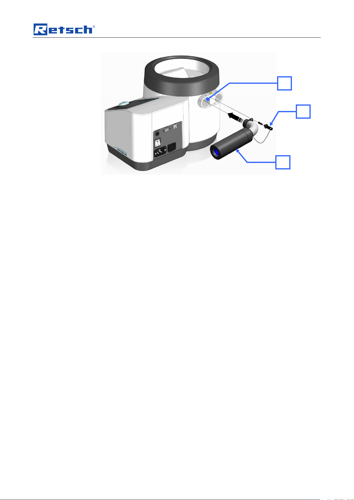
To reduce the suction noise, the provided sound absorber (IS) can be connected to
the air inlet channel (I).
12
Page 13
Pos: 5.13 /0020 Überschriften/1.1 Übersc hriften/1.1 Überschriften BDA/11 Maxi male Belastung @ 0\mod_12289835289 05_9.docx @ 4880 @ 2 @ 1
I
IS
IB
Technical data
Fig. 1: Connecting the sound absorber
Put the position pin (IB) into the opening marked in the picture in order to lock the
sound absorber in a horizontal position.
3.3 Maximum Load
Pos: 5.14 /0005 RETSCH/0005 RETSCH Bedienungsanleitungen Kapitelsammlung en/AS200Jet/0005 AS200Jet Technische D aten/AS200Jet Modul Siebgutmenge M aximale Siebturmmasse @ 1\mod_12 36585803100_9.docx @ 7826 @ @ 1
NOTICE
Ensure that the differential pressure or vacuum generated by your vacuum cleaner
or the suction is not greater than 100 mbar (9999 Pa).
The maximum quantity of material to be sieved depends on the mesh size and
Pos: 5.15 /0020 Überschriften/1.1 Übersc hriften/1.1 Überschriften BDA/11 Schutzart @ 0\mod_1226491839164_9.doc x @ 3328 @ 2 @ 1
sieve size.
3.4 Degree of protection
Pos: 5.16 /0005 RETSCH/0005 RETSCH Bedienungsanleitungen Kapitelsammlung en/AS200Jet/0005 AS200Jet Technische D aten/AS200Jet Modul Schutzart @ 1 \mod_1236585802584_9.docx @ 781 0 @ @ 1
Pos: 5.17 /0020 Überschriften/1.1 Übersc hriften/1.1 Überschriften BDA/11 Abmess ungen und Gewicht Retsch @ 0\mo d_1226492212173_9.docx @ 3352 @ 2 @ 1
– IP40
3.5 Dimensions and weight
Pos: 5.18 /0005 RETSCH/0005 RETSCH Bedienungsanleitungen Kapitelsamml ungen/AS200Jet/0005 AS200Jet Technisch e Daten/AS200Jet Modul Abmessunge n und Gewicht @ 1\mod_1236585800975 _9.docx @ 7770 @ @ 1
Height : 288 mm (without lid)
Width: 460 mm
Depth: 305 mm
Pos: 5.19 /0020 Überschriften/1.1 Übersc hriften/1.1 Überschriften BDA/11 Erforderlic he Standfläche @ 0\mod_1226492 678414_9.docx @ 3364 @ 2 @ 1
Weight: approx. 14 kg
3.6 Required floor space
Pos: 5.20 /0005 RETSCH/0005 RETSCH Bedienungsanleitungen Kapitelsammlung en/AS200Jet/0005 AS200Jet Technische D aten/AS200Jet Modul Erforderliche S tandfläche @ 1\mod_1236585801975 _9.docx @ 7794 @ @ 1
Pos: 5.21 /0020 Überschriften/1.1 Übersc hriften/1.1 Überschriften BDA/11 Nennl eistung @ 0\mod_1226491873164_9.doc x @ 3334 @ 2 @ 1
460 mm x 320 mm; no safety spacing required
3.7 Rated power
Pos: 5.22 /0005 RETSCH/0005 RETSCH Bedienungsanleitungen Kapitelsammlung en/AS200Jet/0005 AS200Jet Tech nische Daten/AS200Jet Modul Nennleistung @ 1\mod_1236585802287_9.docx @ 7 802 @ @ 1
• AS200jet: maximum 50 watts
• AS200jet + HDS200 or GM80 vacuum cleaner: maximum 1450 watts
13
Page 14
Technical data
1 2 3
4 5 6 7 8 9 10
11
12
14
13
Pos: 6.1 /0020 Überschriften/1.1 Übersc hriften/1.1 Überschriften BDA/11 Type nschild Beschreibung @ 3\mod_12809339 53941_9.docx @ 22302 @ 2 @ 1
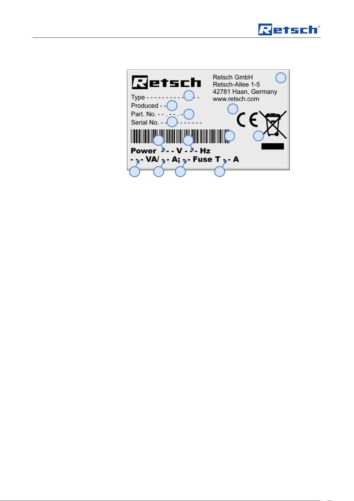
3.8 Type plate description
Pos: 6.2 /0005 RETSCH/0099 RETSCH Standard Kapitel/General Modul Typenschild @ 3\mod_1280931092443_9.doc x @ 22278 @ @ 1
Fig. 2: Type plate lettering
1 Device designation
2 Year of production
3 Part number
4 Serial number
5 Manufacturer’s address
6 CE marking
7 Disposal label
8 Bar code
9 Power version
10 Mains frequency
11 Capacity
12 Amperage
13 Number of fuses
14 Fuse type and fuse strength
In the case of questions please provide the device designation (1) or the part
Pos: 7 /0005 RETSCH/0005 RETSCH Be dienungsanleitungen Kapitelsammlunge n/------- Seitenumbruch ----------- @ 0\mod_1222344373758_0.docx @ 2386 @ @ 1
number (3) and the serial number (4) of the device.
14
Page 15
Transport, scope of delivery, installation
NOTICE
Transport
– Mechanical or electronic components may be damaged.
• The machine may not be knocked, shaken or thrown during
transport.
NOTICE
Temperature fluctuations
The machine may be subject to strong temperature fluctuations during transport
(e.g. aircraft transport)
– The resultant condensed water may damage electronic components.
• Protect the machine from condensed water.
NOTICE
Ambient temperature
– Electronic and mechanical components may be damaged and the
performance data alter to an unknown extent.
• Do not exceed or fall below the permitted temperature range of the
machine (5°C to 40°C / ambient temperature).
CAUTION
V0047
Device falling down
Incorrect erection or insufficient working space
– Due to its weight, the device can inflict personal injury if it falls down.
• Only operate the device on a sufficiently large, strong and stable
workplace.
• Ensure that all feet of the device are positioned securely.
Pos: 8.1 /0020 Überschriften/1. Überschrift en/1 Verpackung, Transport und Aufst ellung @ 0\mod_1226494451893_9.d ocx @ 3380 @ 1 @ 1
4 Transport, scope of delivery, installation
Pos: 8.2 /0020 Überschriften/1.1 Übersc hriften/1.1 Überschriften BDA/11 Verpac kung @ 0\mod_1226495088973_9.docx @ 3392 @ 2 @ 1
4.1 Packaging
Pos: 8.3 /0005 RETSCH/0099 RETSCH Standard Kapitel/General Modul Verpacku ng @ 0\mod_1228984618355_9.doc x @ 4892 @ @ 1
Pos: 8.4 /0020 Überschriften/1.1 Übersc hriften/1.1 Überschriften BDA/11 Transport @ 0\mod_1226495164391_9.docx @ 3398 @ 2 @ 1
4.2 Transport
Pos: 8.5 /0025 Warnhinweise/H0017 HIN WEIS Transport @ 0\mod_1228918883 019_9.docx @ 4802 @ @ 1
Pos: 8.6 /0020 Überschriften/1.1 Übersc hriften/1.1 Überschriften BDA/11 Temperat urschwankungen @ 0\mod_122649 5190738_9.docx @ 3404 @ 2 @ 1
4.3 Temperature fluctuations and condensed water
Pos: 8.7 /0025 Warnhinweise/H0016 HIN WEIS Temperaturschwankungen @ 0\ mod_1233564121287_9.docx @ 5570 @ @ 1
The packaging has been adapted to the mode of transport. It complies with the
generally applicable packaging guidelines.
Pos: 8.8 /0020 Überschriften/1.1 Übersc hriften/1.1 Überschriften BDA/11 Bedingu ngen für den Aufstellort Retsch @ 0\ mod_1226497029322_9.docx @ 3428 @ 2 @ 1
4.4 Conditions for the place of installation
Pos: 8.9 /0005 RETSCH/0099 RETSCH Standard Kapitel/General Modul Umgebungst emperatur 5°C - 40°C @ 0\mod_1 228918538881_9.docx @ 4745 @ @ 1
Pos: 8.10 /0025 Warnhinweise/H0021 H INWEIS Umgebungstemperatur 5°C bis 40 °C @ 0\mod_1228918883441_9.doc x @ 4816 @ @ 1
Pos: 8.11 /0020 Überschriften/1.1 Übersc hriften/1.1 Überschriften BDA/11 Aufstelle n des Gerätes Retsch @ 0\mod_12 26498849756_9.docx @ 3464 @ 2 @ 1
Ambient temperature: 5°C to 40°C
4.5 Installation of the machine
Pos: 8.12 /0025 Warnhinweise/V0047 VORS ICHT Herabfallen des Gerätes / Sta ndfestigkeit @ 3\mod_1282734263400_ 9.docx @ 22780 @ @ 1
15
Page 16
Transport, scope of delivery, installation
CAUTION
V0048
Parts connected to voltage
The power supply is suddenly switched on
– When you switch the device on there is danger of an electrical shock at the
electrical connection for the external suction device.
• Do not touch the electrical connection for the external suction device
and do not insert any parts into the openings.
WARNING
Pos: 8.13 /0005 RETSCH/0099 RETSCH Standard Kapitel/General Modul Aufstell ungshöhe @ 0\mod_1228918538349_9. docx @ 4724 @ @ 1
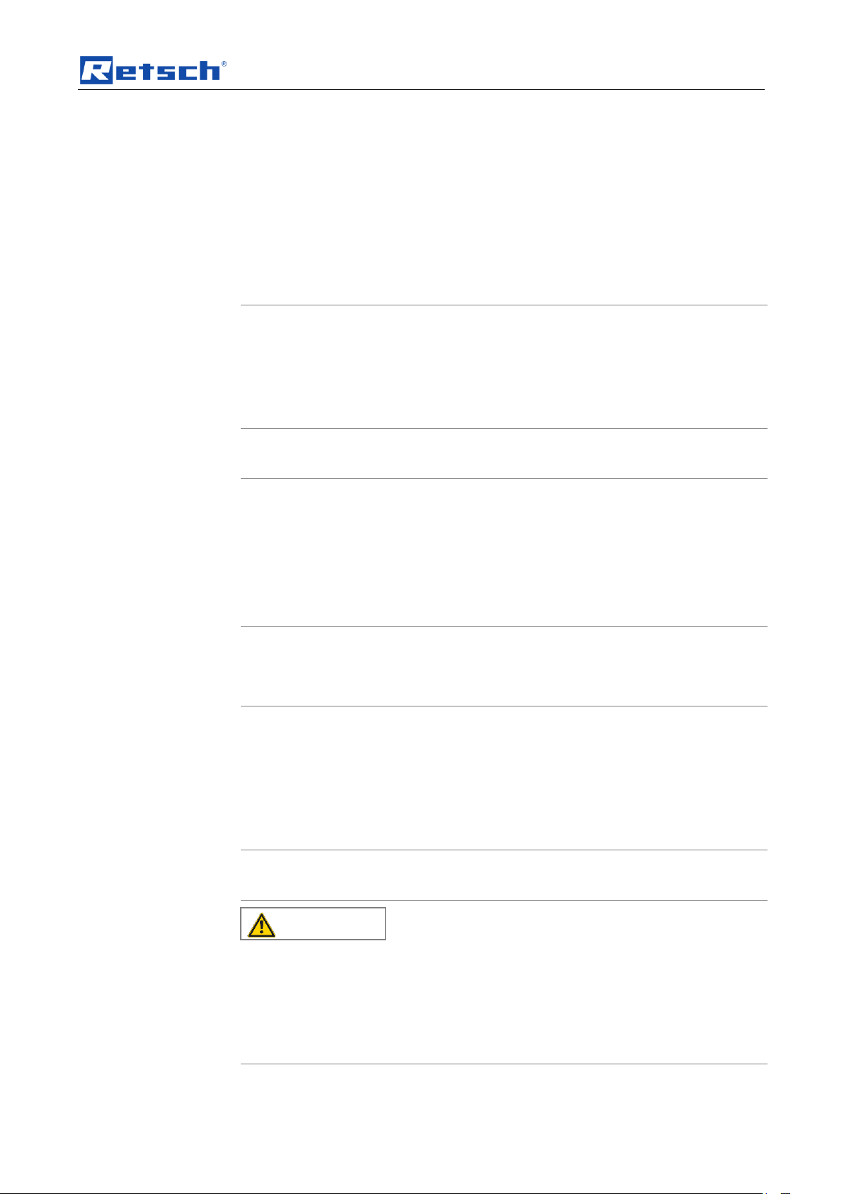
Pos: 8.14 /0005 RETSCH/0005 RETSCH Bedienungsanleitungen Kapitelsamml ungen/AS200Jet/0006 AS200Jet Transport, Lieferumfang und Aufstellen/AS200Jet M odul Grafiken Lufteinlass offen halten @ 3\mod_1307347943605_9.docx @ 2 5260 @ @ 1
Installation height: maximum 2000 m above sea level
Pos: 8.15 /0020 Überschriften/1.1 Üb erschriften/1.1 Überschriften BDA/11 Elektri scher Anschluss @ 0\mod_1226565067 445_9.docx @ 3500 @ 2 @ 1
4.6 Electrical connection
Pos: 8.16 /0025 Warnhinweise/V0048 VORS ICHT Unter Stromspannung stehende Teile (AS200Jet) @ 3\mod_1282734 266259_9.docx @ 22807 @ @ 1
Pos: 8.17 /0005 RETSCH/0099 RETSCH Standard Kapitel/General Modul Elektrisc her Anschluss @ 0\mod_122891853 8521_9.docx @ 4731 @ @ 1
When connecting the power cable to the mains supply, use an external fusethat
complies with the regulations applicable to the place of installation .
• Please check the type plate for details on the necessary voltage and
frequency for the device.
• Make sure the levels agree with the existing mains power supply.
16
Page 17
Pos: 8.18 /0005 RETSCH/0005 RETSCH Bedienungsanleitungen Kapitelsammlung en/AS200Jet/0006 AS200Jet Transport, Li eferumfang und Aufstellen/AS200J et Modul externe Absicherung @ 1\mod _1243926769314_9.docx @ 10385 @ @ 1
WARNING
W0002
Danger to life through electric shock
– An electric shock can lead to burns and to cardiac arrhythmias or to
respiratory arrest and cardiac arrest.
• The device may only be operated with plugs that have a protective
conductor (earthed).
Pos: 8.19 /0025 Warnhinweise/W0015 WARNUNG Kabelbruch Stromstoß Erdung @ 4\mod_1334064762171_9.docx @ 27560 @ @ 1
Pos: 9.1 /0005 RETSCH/0005 RETSCH Bedienungsanleitungen Kapitelsammlunge n/------- Seitenumbruch ----------- @ 0\mod_1222344373758_0.docx @ 2386 @ @ 1
Transport, scope of delivery, installation
• Use the supplied connection cable to connect the device to the mains power
supply.
The external fuse must be at least T15A (230V) T15A (100/120V).
17
Page 18

Operating the machine
A
B
C
D G F
E
Pos: 9.2 /0020 Überschriften/1. Überschrift en/1 Bedienung des Gerätes @ 0\ mod_1226565880211_9.docx @ 3519 @ 1 @ 1
5 Operating the machine
Pos: 9.3 /0020 Überschriften/1.1 Übersc hriften/1.1 Überschriften BDA/11 Ansic hten des Gerätes Retsch @ 0\mod_122 8990581782_9.docx @ 4966 @ 2 @ 1
5.1 Views of the Instrument
Pos: 9.4 /0005 RETSCH Bedienungsanlei tungen Kapitelsammlungen/AS200Jet/00 07 AS200Jet Bedienung/AS200Jet M odul Grafische Ansichten des Gerätes @ 1\ mod_1239699996835_9.docx @ 8127 @ @ 1
Fig. 3: Front view
18
Page 19

Operating the machine
H
I
J K M O P H R
S T L
Fig. 4: Rear view
Fig. 5: View of the sieve compartment (without sieve)
19
Page 20

Operating the machine
C D G F E
Pos: 9.5 /0020 Überschriften/1.1 Übersc hriften/1.1 Überschriften BDA/11 Ansichten der Bedienelemente und der Anzeige @ 0\mod_1226566362336_9.docx @ 3 537 @ 2 @ 1
5.2 Operating elements and displays
Pos: 9.6 /0005 RETSCH Bedienungsanlei tungen Kapitelsammlungen/AS200Jet/00 07 AS200Jet Bedienung/AS200Jet Modul Ansicht der Displayeinheit @ 1\mod _1236682005889_9.docx @ 7916 @ @ 1
Fig. 6: View of the display unit
Pos: 9.7 /0005 RETSCH/0005 RETSCH Bedienungsanleitungen Kapitelsammlunge n/------- Seitenumbruch ----------- @ 0\mod_1222344373758_0.docx @ 2386 @ @ 1
20
Page 21

Operating the machine
Element
Description
Function
A
Lid for air jet sieving
Lid for the test sieve
B
Test sieve
Sieve for the dry sieving and/or particle size
determination
C
Display
Displays the control functions and parameters
D
Start button
Starts sieving
E
Stop button
Stops sieving
F
Operating knob
Dial for changing the device settings
G
Quick start button
Starts quick sieving
H
Air outlet channel
Connection for external exhaust
I
Air inlet channel
Opening for air inlet
J
Connection for automatic air flow
regulation
Connector socket for external air flow regulation
K
Serial PC - Port (RS232)
PC connection for data communication with
EasySieve®
L
USB interface
PC connection for data communication with
EasySieve®
M
On/Off switch
Disconnects the device from the mains / including
thermal and switchable power fuse
O
IEC C14 appliance inlet
Mains connection
P
IEC C13 connector
Power connection for the external vacuum cleaner
R
Cover for differential pressure sensor
Protects the differential pressure sensor
S
Air nozzle
Conducts the air jet upwards onto the sieve
T
Nozzle compartment
Feeds the material to be sieved to the air outlet
channel
Pos: 9.8 /0020 Überschriften/1.1 Übersc hriften/1.1 Überschriften BDA/11 Übersichtst abelle der Geräteteile @ 0\mod_12 28990616846_9.docx @ 4972 @ 2 @ 1
5.3 Overview table of the parts of the device
Pos: 9.9 /0005 RETSCH Bedienungsanlei tungen Kapitelsammlungen/AS200Jet/00 07 AS200Jet Bedienung/AS200Jet Modul T abelle der Geräteteile @ 1\mod_12 39875152197_9.docx @ 8150 @ @ 1
Pos: 9.10 /0005 RETSCH/0005 RETSCH Bedienungsanleitungen Kapitelsammlung en/------- Seitenumbruch ----------- @ 0\mod_1222344373758_0.docx @ 2386 @ @ 1
21
Page 22

Operating the machine
T
A
Pos: 9.11 /0020 Überschriften/1.1 Übersc hriften/1.1 Überschriften BDA/11 Arbeits weise Retsch @ 0\mod_1228990496 537_9.docx @ 4960 @ 2 @ 1
5.4 Working procedure
Pos: 9.12 /0005 RETSCH Bedienungsa nleitungen Kapitelsammlungen/AS200Jet /0007 AS200Jet Bedienung/AS200Jet Mo dul Arbeitsweise @ 1\mod_1243413970 772_9.docx @ 9550 @ @ 1
The AS 200 jet has an air nozzle, which is set rotating. The sieve with lid is put on
top of that. A vacuum unit generates a jet of air, which disperses the particles
through the air nozzle on the sieve. The material, which is smaller than the sieve’s
mesh size is transported by the backflow of the air into the cyclone or directly into
the vacuum cleaner. The jet of air de-agglomerates the particles and cleans the
Pos: 9.13 /0020 Überschriften/1.1 Übersc hriften/1.1 Überschriften BDA/11 Ein- / Ausschalten @ 0\mod_1229416527496_ 9.docx @ 5058 @ 2 @ 1
sieve mesh constantly.
5.5 Switching On and Off
Pos: 9.14 /0005 RETSCH Bedienungsa nleitungen Kapitelsammlungen/AS200Jet /0007 AS200Jet Bedienung/AS200Jet Mo dul Ein und Ausschalten @ 1\mod_1239 194085237_9.docx @ 8018 @ @ 1
• Press the on/off switch (M) at the back to turn on the device.
When the switch is in the "off" position, the device must be disconnected
Pos: 9.15 /0020 Überschriften/1.1 Übersc hriften/1.1 Überschriften BDA/11 Einsetze n des Analysesiebes @ 1\mod_1236 591586574_9.docx @ 7875 @ 2 @ 1
completely from the mains power supply.
5.6 Inserting the test sieve
Pos: 9.16 /0005 RETSCH Bedienungsa nleitungen Kapitelsammlungen/AS200Jet/0 007 AS200Jet Bedienung/AS200Jet Modul Einsetzen des Analysesiebes @ 1\ mod_1239194012458_9.docx @ 8004 @ 3 @ 1
The AS200jet is intended for Retsch test sieves with a diameter of 203mm (8
inches) and a height of 25mm (1 inch) or 50mm (2 inches). The range of mesh
fineness extends from 10µm to approx. 4mm.
Fig. 7: Inserting the test sieve
Place the sieve in the nozzle compartment (T).
Close the sieve with the air jet sieve lid (A) intended for the respective sieve height.
NOTE
The AS200jet cannot be started until the sieve has been inserted and the lid put
on.
22
Page 23

Operating the machine
WARNING
W0007
Electric shock
Faulty power cable
– When you switch the device on there is danger of an electrical shock if the
power cable for the external suction device is damaged.
• Before use, check the power cable between the sieve device and the
suction device for possible damage.
• Never use a damaged power cable!
2
1
5.6.1 Sieve lid for 50--mm/25--mm sieve height
Fig. 8: Sieve lid
The sieve lid for 50-mm (2-inch) sieves lies on the top edge of the sieve (1).
Pos: 9.17 /0020 Überschriften/1.1 Übersc hriften/1.1 Überschriften BDA/11 Schonha mmer – Anwendung und Gebrauch @ 2\mod_1256728342926_9.docx @ 174 60 @ 2 @ 1
The sieve lid for 25-mm (1-inch) sieves lies on the ledge inside the sieve (2).
5.7 Soft-faced mallet – Application and Use
Pos: 9.18 /0005 RETSCH Bedienungsa nleitungen Kapitelsammlungen/AS200Jet/0 007 AS200Jet Bedienung/AS200jet Mo dul Schonhammer verwenden @ 2\ mod_1256728441363_9.docx @ 17467 @ @ 1
Any caking that has built up during the sieving process is knocked off the inside of
the lid by means of the soft-faced mallet.
Tap lightly, striking the centre of the knob as far as possible.
Pos: 9.19 /0020 Überschriften/1.1 Übersc hriften/1.1 Überschriften BDA/11 Anschluss des externen Industrie-Saugers R etsch @ 1\mod_1239966706099_9.docx @ 8160 @ 2 @ 1
Fig. 9: Using the soft-faced mallet
5.8 Connecting the external Industrial Vacuum cleaner
Pos: 9.20 /0025 Warnhinweise/W0007 WARNUNG Stromschlag Defektes Stromka bel (AS200Jet) @ 3\mod_128273426 7244_9.docx @ 22816 @ @ 1
23
Page 24

Operating the machine
CAUTION
Objects thrown-out or falling down
Connection of compressed air instead of vacuum cleaner
– If compressed air is connected to one of the two air openings, the sieve lid
and the sieve will be hurled out.
• This device may not be operated with compressed air.
CAUTION
H
P
Pos: 9.21 /0025 Warnhinweise/V0049 V ORSICHT Herausgeworfenen Gegenstä nde (AS200Jet) @ 3\mod_128273426436 9_9.docx @ 22789 @ @ 1
Pos: 9.22 /0005 RETSCH Bedienungsa nleitungen Kapitelsammlungen/AS200Jet/0 007 AS200Jet Bedienung/AS200Jet Modul Anschluss Industrie Staubsauger @ 1\mod_1239966838301_9.docx @ 8167 @ 3 @ 1
The AS200jet can be operated only with a suction extractor, such as for example a
vacuum cleaner. We recommend the use of the Retsch industrial vacuum cleaner,
which is available as an accessory.
Before starting to use the Retsch industrial vacuum cleaner, read the
accompanying operating manual.
Fig. 10: Connection of the Retsch industrial vacuum cleaner
• As required, connect the manual suction force adjuster to the
air outlet channel (H).
• Connect your vacuum cleaner’s suction tube to the air outlet
channel (H) or to the manual suction force adjuster.
• Insert the type F IEC C14 connector on the vacuum cleaner
into the IEC C13 panel-mounted outlet (P).
The power for the Retsch industrial vacuum cleaner is supplied from the AS200jet.
5.8.1 Vacuum cleaner function
By means of the vacuum cleaner menu item, the industrial vacuum cleaner
connected to the IEC C13 panel-mounted outlet (P) can be used for cleaning the
device too.
• Pull the industrial vacuum cleaner’s suction hose out of the air outlet channel
(H).
• Navigate to the menu item Manual suction apparatus.
• Press the start button.
24
Page 25

Pos: 9.23 /0020 Überschriften/1.1 Übersc hriften/1.1 Überschriften BDA/11 Steueru ng der Luftstrom-Stärke @ 1\mod_12 40308048818_9.docx @ 8180 @ 2 @ 1
NB
H0051
Objects are sucked in
Vacuum in the sieve area
– Small objects can be sucked into the inside of the machine.
• No small objects or parts of the body may be placed near the suction
opening.
CAUTION
V0050
Failure to hear acoustic signals
Loud suction noise on the air inlet
– It is possible that some acoustic warnings and voice communication may
not be noticed.
• Take the strength of the suction noise into consideration when
designing your acoustic signals in the working environment.
Possibly additionally use visual signals.
U
1
1
2
3 4
V
U
V
Pos: 9.24 /0020 Überschriften/1.1.1. Übersc hriften/111 Manuelle Steuerung der Luftstr omstärke @ 1\mod_124030929594 3_9.docx @ 8201 @ 3 @ 1
Pos: 9.25 /0025 Warnhinweise/H0051 H INWEIS Gegensstände werden anges augt (AS200Jet) @ 3\mod_1282734261369 _9.docx @ 22762 @ @ 1
Pos: 9.26 /0025 Warnhinweise/V0050 VORS ICHT Überhören akustischer Signale ( AS200Jet) @ 3\mod_1282734265322 _9.docx @ 22798 @ @ 1
Operating the machine
• To turn the vacuum cleaner off, press the STOP button or use the turn-andpush dial.
Pos: 9.27 /0005 RETSCH Bedienungsa nleitungen Kapitelsammlungen/AS200Jet/0 007 AS200Jet Bedienung/AS200Jet Modul manuelles Verstellen des Luftstro mes (Querschnitt) @ 1\mod_12403096044 54_9.docx @ 8222 @ @ 1
Fig. 11: Air jets through the manual suction force adjuster
Fig. 12: Manual adjustment of the air jet (cross section)
25
Page 26

Operating the machine
The air jet can be changed by turning the manual air jet setting (U).
[1] Air entry opening (V) closed maximum air jet
[2] Air entry opening (V) open minimum air jet
The difference in air pressure (differential pressure) between the air inlet and air
Pos: 9.28 /0005 RETSCH Bedienungsa nleitungen Kapitelsammlungen/AS200Jet/0 007 AS200Jet Bedienung/AS200Jet Modul Anschließen Manuelle Saugkraft verstellung @ 3\mod_1290606663037_9.doc x @ 24030 @ @ 1
outlet at a given moment is displayed on the screen.
Pos: 9.29 /0005 RETSCH/0005 RETSCH Bedienungsanleitungen Kapitelsammlung en/------- Seitenumbruch ----------- @ 0\mod_1222344373758_0.docx @ 2386 @ @ 1
Fig. 13: connecting the manual suction force adjuster
26
Page 27

Operating the machine
to .
to .
Pos: 9.30 /0020 Überschriften/1.1 Übersc hriften/1.1 Überschriften BDA/11 Displa yeinheit - Bedienung des Gerätes @ 1\ mod_1236677049299_9.docx @ 7890 @ 2 @ 1
Pos: 9.31 /0005 RETSCH/0099 RETSCH Standard Kapitel/General Modul Displa yeinheit - Bedienung des Gerätes @ 1\m od_1236681950483_9.docx @ 7908 @ 33 @ 1
This device offers a new, very convenient operator guidance. All relevant data can
be entered or retrieved by means of a graphics display with one-button operation.
The menu guidance is in several languages.
5.8.1 Setting options using the display menu
The selection bar in the display should be operated as follows:
Rotation function I)
• Turn the operating button to get to the various menu points. The selected
menu points are marked by the dark selection bar. Areas which cannot be
changed are skipped.
Rotation function II)
• Turn the operating button to change figures and decisions in the menu
points.
Press I)
• Press the operating button to open selected menu points.
Press II)
• Press the operating button to confirm settings.
Press III)
• Keeping the operating button pressed takes you back to the basic screen
(level 1).
5.8.2 Navigation between operating modes
• Turn the operating button clockwise until the dark line cursor is in the
navigation menu (C1).
• Press the operating button (F).
– The icon for scrolling direction (C4) changes from
• By turning the operating button, switch between the operating modes
manual, Program 01 to 09, Quick Start and basic settings.
• To activate the selected operating mode, press the operating button (F).
– The icon for scrolling direction (C4) changes from
• By turning the operating button, switch to the sub-points of the selected
menu point.
27
Page 28
Operating the machine
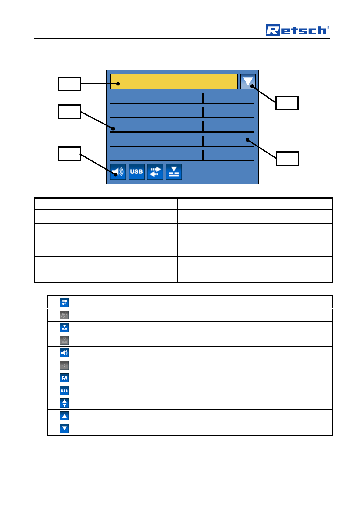
Element
Description
Function
C1
Menu navigation
Switch between manual, program and basic settings
C2
Specification of sieve parameters
Sieve parameter display and adjustment
C3
Icons for device functions
Display of function statuses of sound, interface, Open
Mesh and automatic vacuum force adjustment
C4
Icon for scrolling direction
Shows possible scrolling directions
C5
Sieve parameters
Display of values
Open Mesh switched on (see Open Mesh chapter)
Open Mesh switched off
Automatic vacuum adjustment connected
No automatic vacuum adjustment
Signal tone on
Signal tone off
RS232 interface active
USB interface active
Scrolling up or down possible
Scrolling up only is possible
Scrolling down only is possible
MANUAL
SIEVE DURATION
SPEED
VACUUM
OPEN MESH
SAVE PARAMETERS
00:10 mm:ss
05 rpm
0000 Pa
ON
C4
C1
C5
C2
C3
Pos: 9.32 /0020 Überschriften/1.1 Übersc hriften/1.1 Überschriften BDA/11 Symbol e in der Displayeinheit @ 1\mod_12499 91350589_9.docx @ 13770 @ 2 @ 1
5.9 Symbols in the Display Unit
Pos: 9.33 /0005 RETSCH Bedienungsa nleitungen Kapitelsammlungen/AS200Jet /0007 AS200Jet Bedienung/AS200Jet Mo dul Grafikdisplay Menü neu @ 7\mod_ 1386159686424_9.docx @ 53360 @ @ 1
Fig. 1: View of the menu in the display unit
Pos: 9.34 /0005 RETSCH Bedienungsa nleitungen Kapitelsammlungen/AS200Jet /0007 AS200Jet Bedienung/AS200Jet Mo dul Symbole in der Displayeinheit neu @ 1 \mod_1239194092534_9.docx @ 809 8 @ @ 1
Pos: 9.35 /0005 RETSCH/0005 RETSCH Bedienungsanleitungen Kapitelsamml ungen/------- Seitenumbruch ----------- @ 0\mod_1222344373758_0.docx @ 2386 @ @ 1
28
Page 29

Operating the machine
Pos: 9.36 /0020 Überschriften/1.1 Übersc hriften/1.1 Überschriften BDA/11 Direktz ugriff auf das Sprachenmenü @ 7\mod_ 1386851099017_9.docx @ 53612 @ 2 @ 1
5.10 Direct access to the language menu
Pos: 9.37 /0005 RETSCH Bedienungsa nleitungen Kapitelsammlungen/AS200Jet/0 007 AS200Jet Bedienung/AS200jet Mo dul Spracheinstellungen extra @ 7\mod _1386769736915_9.docx @ 53474 @ @ 1
If you have inadvertently set the wrong language you can go straight to the
language menu using the following steps.
• Switch the device off by the main switch.
• Switch the device on, simultaneously pressing the buttons START - STOP -
QUICK START.
• After selecting the correct language, switch the device off and immediately
back on.
• Confirm your selection by pressing the operating button.
The device has now been permanently set to your language and you are in the
main menu.
Pos: 9.38 /0005 RETSCH/0005 RETSCH Bedienungsanleitungen Kapitelsammlung en/------- Seitenumbruch ----------- @ 0\mod_1222344373758_0.docx @ 2386 @ @ 1
29
Page 30

Operating the machine
Manual
Sieve duration
Speed
Vacuum
Open Mesh
Save parameters
Program
Save
Back Suction apparatus
Program [01 - 09]
Sieve duration
Speed
Vacuum
Open Mesh
Change program
Program
Sieve duration
Speed
Vacuum
Open Mesh
Save
Back Delete program
Program
Delete
Back
Quick Start
Sieve duration
Speed
Vacuum
Open Mesh
Change program
Program
Sieve duration
Speed
Vacuum
Open Mesh
Save
Back
Delete program
Basic settings
Vacuum
Languages
Brightness
Date Time Signal tone
Interface
Service
Operating hours
Display software version
Controller software version
Software updates
Display
Start
Back Controller
Start
Back Back
Calibrate sensor
Service level
Calibrate rotation speed
Test motor
Back
Back
Pos: 9.39 /0020 Überschriften/1.1 Übersc hriften/1.1 Überschriften BDA/11 Menüstr uktur @ 1\mod_1239699858524_9.doc x @ 8120 @ 2 @ 1
5.11 Menu structure
Pos: 9.40 /0005 RETSCH Bedienungsa nleitungen Kapitelsammlungen/AS200Jet/0 007 AS200Jet Bedienung/AS200jet Mo dul Gesamtmenüstruktur 01 @ 7\mod _1386754070774_9.docx @ 53451 @ @ 1
Overview of all menu points:
30
Page 31

Operating the machine
G
Pos: 9.41 /0020 Überschriften/1.1 Üb erschriften/1.1 Überschriften BDA/11Betri ebsmodi @ 7\mod_1386851520343_9.doc x @ 53623 @ 2 @ 1
5.12 Operating modes
Pos: 9.42 /0005 RETSCH Bedienungsa nleitungen Kapitelsammlungen/AS200Jet/0 007 AS200Jet Bedienung/AS200jet Mo dul Betriebsmodi @ 7\mod_13867699 49365_9.docx @ 53496 @ 2444 @ 1
You can select the following operating modes using the menu navigation (C1):
5.12.1.1 Manual
If this function has been set, all parameters and functions can be retrieved and
changed at any time. This is also possible while sieving.
5.12.1.2 Program 01 to 09
In programs 01 to 09 the previously set parameters such as sieve duration, speed,
vacuum (only with connected automatic suction force adjustment) and Open Mesh
can be saved in a memory.
5.12.1.3 Quick Start
Under the Quick Start menu point, as with a program you can save previously set
parameters such as sieve duration, speed, vacuum (only with connected automatic
suction force adjustment) and Open Mesh in a memory.
The Quick Start sieving can also be started directly using
the Quick Start button (G).
– The Quick Start button has no function if you are in a settings menu.
Fig. 2: Quick Start button
5.12.1.4 Basic settings
In this settings menu, you can perform the following device settings:
– Vacuum
– Languages
– Brightness
– Date
– Time
– Signal tone
– Interface
– Service
31
Page 32

Operating the machine
Open Mesh switched on
Open Mesh switched off
P
Pos: 9.43 /0020 Überschriften/1.1 Übersc hriften/1.1 Überschriften BDA/11 Manueller Betrieb @ 7\mod_1386773101603_ 9.docx @ 53507 @ 3 @ 1
5.13 Manual operation
Pos: 9.44 /0005 RETSCH Bedienungsa nleitungen Kapitelsammlungen/AS200Jet/0 007 AS200Jet Bedienung/AS200jet Mo dul Manueller Betrieb @ 7\mod_138677 4886925_9.docx @ 53540 @ 233333 @ 1
5.13.1 Sieve duration
00:01 to 99:59 (minutes : seconds)
5.13.2 Speed
5 to 55 revolutions per minute (10 revolutions per minute “Open Mesh”
5.13.3 Vacuum
You can adjust the vacuum when the automatic suction force adjustment has been
connected. (Pa; mbar; psi)
5.13.4 Open Mesh
Display whether Open Mesh is active: YES / NO
The air nozzle is moved two steps in the direction of rotation and then one step
back. The speed is fixed when Open Mesh is switched on to 10 revolutions per
minute.
5.13.5 Save parameters
All previously set parameters such as sieve duration, speed, vacuum (only with
connected automatic suction force adjustment) and Open Mesh can be saved in a
memory here.
• Set the desired parameters.
• By turning the operating button (F), switch to the menu point Save
• Press the operating button (F).
– The Save parameters menu opens and the dark line cursor is on Program.
• Press the operating button (F) to select a program memory location or Quick
• By turning the operating button (F) switch to the desired memory location.
• Press the operating button (F) to exit the memory location selection.
• Select either
– Save to save settings or
– back to cancel without saving.
5.13.6 Suction apparatus
parameters.
Start.
32
Fig. 3: Connector (electrical connection for the external suction apparatus)
Using the suction apparatus menu point, you can switch on the vacuum cleaner
connected to the connector (P) independently of sieving.
• By turning the operating button (F) switch to the suction apparatus menu
point.
Page 33

Operating the machine
Open Mesh switched on
Open Mesh switched off
• Press the operating button (F).
– The Off display appears in the suction apparatus menu point.
• Press the START button to switch the power on.
• Press the STOP button to turn the power off.
• Press the operating button (F) to exit the suction apparatus menu point.
Pos: 9.45 /0020 Überschriften/1.1 Übersc hriften/1.1 Überschriften BDA/11 Program m @ 5\mod_1344511635554_9.docx @ 33985 @ 2 @ 1
5.14 Programs
Pos: 9.46 /0005 RETSCH Bedienungsa nleitungen Kapitelsammlungen/AS200Jet /0007 AS200Jet Bedienung/AS200jet Mo dul Programme @ 7\mod_1386774927 066_9.docx @ 53551 @ 233344 @ 1
5.14.1 Sieve duration
Display of the stored sieve duration:
00:01 to 99:59 (minutes : seconds)
5.14.2 Speed
Display of the stored speed:
5 to 55 revolutions per minute (10 revolutions per minute “Open Mesh”)
5.14.3 Vacuum
Display of the vacuum with connected automatic vacuum force adjustment.
5.14.4 Open Mesh
Display whether Open Mesh is active: YES / NO
NOTE
The air nozzle is moved two steps in the direction of rotation and then one step
back. The speed is fixed when Open Mesh is switched on to 10 revolutions per
minute.
5.14.4.1 Change program
In this menu you can change the stored parameters of each program incl. Quick
Start.
• By turning the operating button (F) switch to the Change program menu
• Press the operating button (F).
– The Save parameters menu opens and the dark line cursor is on Program.
NOTE
You can change the active or any other program.
• Press the operating button (F) to activate the program selection.
• By turning the operating button (F) switch to the desired memory location.
• Press the operating button (F) to exit the memory location selection.
• Set the desired sieve parameters.
• Finally select either
point.
- Save to save the settings or
33
Page 34

Operating the machine
- Back to cancel without saving.
– This returns you to the program level.
NOTE
A program which has not been saved cannot be started.
5.14.4.2 Delete program
In this menu you can delete the stored parameters of each program.
NOTE
Only the parameters saved in the respective program are deleted. The program
memory location remains in place. The parameters in the Quick Start program
cannot be deleted.
• By turning the operating button (F) switch to the Delete program menu point.
• Press the operating button (F).
– The Delete program menu opens and the dark line cursor is on Program.
• Press the operating button (F) to activate the program selection.
• By turning the operating button (F) switch to the desired program.
• Press the operating button (F) to exit the program selection.
• Finally select either
– Delete to delete the settings or
– Back to cancel without deleting.
Pos: 9.47 /0020 Überschriften/1.1 Übersc hriften/1.1 Überschriften BDA/11 Quick Start @ 7\mod_1386773204943_9.doc x @ 53518 @ 2 @ 1
– You return to the program level.
5.15 Quick Start
Pos: 9.48 /0005 RETSCH Bedienungsa nleitungen Kapitelsammlungen/AS200Jet/0 007 AS200Jet Bedienung/AS200jet Mo dul Quick Start @ 7\mod_138677493167 6_9.docx @ 53563 @ @ 1
Pos: 9.49 /0020 Überschriften/1.1 Übersc hriften/1.1 Überschriften BDA/11 Grundein stellungen neu @ 7\mod_138753561 4794_9.docx @ 53850 @ 2 @ 1
5.16 Basic settings
Pos: 9.50 /0005 RETSCH Bedienungsa nleitungen Kapitelsammlungen/AS200Jet/0 007 AS200Jet Bedienung/AS200jet Mo dul Grundeinstellungen @ 7\mod_1386 774936450_9.docx @ 53575 @ 33333333 44445543 @ 1
5.16.1 Vacuum
Fig. 4: Quick Start button
Using the QUICK START button you can start sieving directly with the parameters
saved in the Quick Start program location.
(see programs)
NOTE
No sieving can be started while the basic settings menu is active.
You can set the display unit for the vacuum in this menu:
– Pa
– mbar;
– psi
5.16.2 Languages
5.16.3 Brightness
34
You can selecte the languages menu here. After selecting and pressing the
operating button, the entire menu structure is displayed in your language.
The brightness can be adjusted to the respective user or environment (sunshine,
glare etc.).
Page 35

5.16.4 Date
Signal tone on
Signal tone off
RS232 interface active
USB interface active
K
L
5.16.5 Time
5.16.6 Signal tone
5.16.7 Interface
Operating the machine
The current date can be entered here.
The device can be disconnected from the mains for up to 30 days without losing
the settings.
The time can be entered here.
The time then appears in the stand-by screen.
The device can be disconnected from the mains for up to 30 days without losing
the settings.
The error messages on incorrect operation can be supported by an acoustic signal
tone. When the function is switched off, the corresponding pictogram appears
Fig. 5: Interfaces
In this menu you can switch from using the RS232 (K) or the USB (L) interface.
5.16.8 Service
5.16.8.1 Operating hours
The hours counted are sieving hours, i.e. the total times between START and
STOP. The times cannot be manipulated.
5.16.8.2 Software version display
Shows the software version of the display.
5.16.8.3 Software version controller
Shows the software version of the controller.
5.16.8.4 Update software
5.16.8.4.1 Display
– The target display unit is selected on the PC via a software update selection
menu.
35
Page 36

Operating the machine
– The data are sent by the connected PC via interface cable (RS232 or USB)
to the controller PCB. The controller PCB forwards the data on to the boot
loader of the display unit.
5.16.8.4.2 Controller
– The target device controller is selected on the PC via a software update
selection menu.
– The data are sent by the connected PC via interface cable (RS232 or USB)
to the controller PCB. The controller PCB forwards the data on to the boot
loader of the display unit.
5.16.8.5 Sensor calibration
See chapter “pressure sensor calibration”
5.16.9 Service level
NOTE
Access to this menu point is exclusively permitted for service employees or
Pos: 9.51 /0020 Überschriften/1.1 Übersc hriften/1.1 Überschriften BDA/11 Starten, Un terbrechen, Stoppen @ 0\mod_12 29417133049_9.docx @ 5070 @ 3 @ 1
authorised service personnel.
5.17 Starting, Interrupting, Stopping
Pos: 9.52 /0005 RETSCH Bedienungsa nleitungen Kapitelsammlungen/AS200Jet/0 007 AS200Jet Bedienung/AS200Jet Modul Starten Stoppen @ 1\mod_12391 94086237_9.docx @ 8026 @ @ 1
• Switch the device on by pressing the on/off switch at the back.
• Use the operating knob (F) to set the sieving parameters you want.
• Put the test sieve with the sample onto the nozzle compartment.
• Place the lid on the sieve.
NOTE
The sieving will not start if the lid is not on.
• Start sieving by pressing the START button (D).
• You can also start the air jet sieving directly by pressing the QUICK START
Pos: 9.53 /0020 Überschriften/1.1 Übersc hriften/1.1 Überschriften BDA/11 Quick S tart - Tastenfunktion @ 1\mod_1240 313233592_9.docx @ 8229 @ 2 @ 1
Pos: 9.54 /0005 RETSCH Bedienungsa nleitungen Kapitelsammlungen/AS200Jet/0 007 AS200Jet Bedienung/AS200Jet Modul Quick Start Tastenfunktion @ 1\mod _1239194087706_9.docx @ 8042 @ @ 1
Pos: 9.55 /0020 Überschriften/1.1 Übersc hriften/1.1 Überschriften BDA/11 Stand-b y @ 7\mod_1386841122969_9.doc x @ 53601 @ 2 @ 1
key (G). (see chapter on Quick Start key functions)
The QUICK START (G) key can be used to start a pre-programmed sieving
process directly without accessing the menu.
5.18 Stand-by
Pos: 9.56 /0005 RETSCH Bedienungsa nleitungen Kapitelsammlungen/AS200Jet/0 007 AS200Jet Bedienung/AS200jet Mo dul Stand-By-Monitor @ 7\mod_1386841015177_ 9.docx @ 53590 @ @ 1
36
After the device has been inactive for 15 minutes (time after a STOP command),
the stand-by screen switches on automatically.
By pressing one of the buttons or touching the operating button, the stand-by
screen disappears without executing the command given.
If you were in a sub-menu when the stand-by screen was activated, you return
automatically to this selection window.
NOTE
The stand-by screen cannot be deactivated.
Page 37
Operating the machine
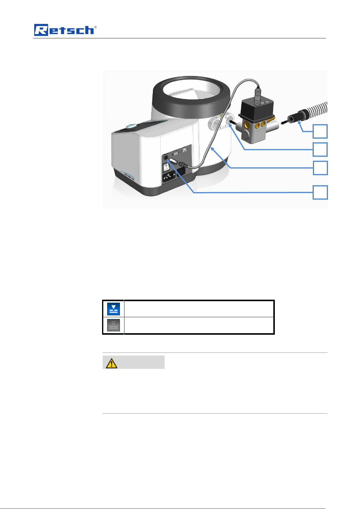
Automatic vacuum force adjustment connected
No automatic vacuum force adjustment
WARNING
W0002
Danger to life through electric shock
– An electric shock can lead to burns and to cardiac arrhythmias or to
respiratory arrest and cardiac arrest.
• The device may only be operated with plugs that have a protective
conductor (earthed).
SK
J IS
H
Pos: 9.57 /0020 Überschriften/1.1.1. Übersc hriften/11 Anschluss der geregelten S augkrauftsteuerung @ 1\mod_1240308 097272_9.docx @ 8187 @ 1 @ 1
5.19 Controlled suction force adjuster
Pos: 9.58 /0005 RETSCH Bedienungsa nleitungen Kapitelsammlungen/AS200Jet/0 007 AS200Jet Bedienung/AS200Jet Modul Anschluss des Motor-Regelventils @ 1\mod_1240309232193_9.docx @ 8194 @ @ 1
Fig. 14: Connecting the automatic suction force adjuster
The automatic suction force adjuster available as a Retsch accessory allows the air
jet force to be controlled automatically. The AS200jet measures the momentary
differential pressure and controls the automatic suction force adjuster accordingly.
• Insert the automatic suction force adjuster into the air outlet channel (H) as
• Connect the automatic suction force adjuster’s control cable (SK) to the
• Connect the industrial vacuum cleaner’s suction tube to the opening (IS).
As long as the automatic suction force adjuster’s control cable is connected, the
following symbol appears in the display:
Pos: 9.59 /0020 Überschriften/1.1 Übersc hriften/1.1 Überschriften BDA/11 Zyklon M ontage @ 2\mod_1277451406744_9. docx @ 20490 @ 3 @ 1
5.20 Cyclone assembly
Pos: 9.60 /0025 Warnhinweise/W0015 WARNUNG Kabelbruch Stromstoß Erdung @ 4\mod_1334064762171_9.docx @ 27560 @ @ 1
shown in the picture.
control connection (J).
37
Page 38

Operating the machine
CAUTION
Risk of explosion or fire
Changing sample characteristics
– Note that the characteristics and accordingly the danger presented by a
sample can change during sieving.
• Do not sieve any potentially explosive or combustible materials in
this device.
Element
Description
Function
Z1
Knurled head screw
Fastens the cyclone
Z2
Pin
Anti-rotation device for support Z3
Z3
Housing support for cyclone
Cyclone support
Z4
Fixing screw
Fastens the cyclone support
Z5
Manual suction power adjuster
To adjust the air current
Z1
Z3
Z4
Z5
Z6
Z9
Z2
Z7
Z8
Pos: 9.61 /0025 Warnhinweise/V0003 VORS ICHT Explosions- oder Brandgefa hr Sieben @ 1\mod_1243924323407_9.d ocx @ 10360 @ @ 1
Pos: 9.62 /0005 RETSCH Bedienungsa nleitungen Kapitelsammlungen/AS200Jet/0 007 AS200Jet Bedienung/AS200jet Mo dul Hinweis Elektrostatische Aufladung @ 4\mod_1338364384983_9.docx @ 29490 @ @ 1
Electrostatic charge inside the devices is prevented by earthing the device via the
protective conductor on the electrical connection. Ensure the correct assembly of
the cyclone in order to guarantee sufficient earthing.
NOTICE
Despite this, electrostatic charge separation may however still occur between the
sample and receptacle wall inside the collecting receptacle (Z9) depending on the
Pos: 9.63 /0005 RETSCH Bedienungsa nleitungen Kapitelsammlungen/AS200Jet /0007 AS200Jet Bedienung/AS200Jet Mo dul Zyklon Anschließen @ 2\mod_127 7131181425_9.docx @ 20450 @ @ 1
sample property, flow speed and air humidity.
Fig. 15: Individual cyclone parts
38
Page 39

Operating the machine
Z6
Air outlet
Connection for the industrial vacuum cleaner
Z7
Cyclone cover
Removable cover with air outlet
Z8
Cyclone
Separates sample material from air current
Z9
Collecting vessel
Collecting tank for sieved sample material
Z2
Z3
Fig. 16: Connection of the cyclone
Fig. 17: Steps 1 and 2
1. Push the pin (Z2) into the upper opening on the outer edge of the housing.
2. Push the cyclone support (Z3) onto the pin.
39
Page 40

Operating the machine
Z4
Z5
H
Z1
Fig. 18: Steps 3 and 4
3. Screw the screw (Z4) in.
4. Push the manual suction power adjuster (Z5) into the air outlet‘ (H).
40
Fig. 19: Steps 5 and 7
5. Push the cyclone with cover into the manual suction power adjuster.
Position the cyclone with cover such that the support on the cyclone fits into
the housing support (Z3).
6. Screw the knurled head screw (Z1) into the housing support.
Page 41

Pos: 10 /0005 RETSCH/0005 RETSCH B edienungsanleitungen Kapitelsammlung en/------- Seitenumbruch ----------- @ 0\mod_1222344373758_0.docx @ 2386 @ @ 1
Operating the machine
Fig. 20: Connect the vacuum cleaner
7. Place the hose of the vacuum cleaner in the upper opening of the cyclone.
41
Page 42

EasySieve®
K
L
Pos: 11.1 /0005 RETSCH/0015 RETSCH Reparatur- und Montageanleitungen/ 00000 Überschriften/1. Überschriften/1 E asySieve® @ 0\mod_1229520770280_9.d ocx @ 5246 @ 2 @ 1
6 EasySieve®
Pos: 11.2 /0020 Überschriften/1.1 Übersc hriften/1.1 Überschriften Software BDA1 1 Steuern, auswerten, dokumentieren @ 0 \mod_1231151811461_9.docx @ 5357 @ 2 @ 1
6.1 Control, evaluation, documentation
Pos: 11.3 /0010 RETSCH Standard KapitelG eneral Modul EasySieve @ 0\mo d_1231151891210_9.docx @ 5363 @ @ 1
EasySieve®, the software package from RETSCH for grain size analyses, is
superior to manual evaluation in many respects. This is because the software is
able to perform the required measuring and weighing processes automatically –
from determining the weights of the sieves to evaluating the data. And in a much
more simple and comfortable manner – thus making life “easier”.
The software is structured in a self-explanatory way and follows the logical chain of
events involved in analysing grain sizes. This makes it possible to use it with
confidence in a fairly short time. The multiplicity of evaluation options additionally
provides the utmost flexibility in adapting to demanding, individual applications.
Abb. 21: Parameter input – Trend analysis of product processes - Comparison with specification limits
Pos: 11.4 /0020 Überschriften/1.1 Übersc hriften/1.1 Überschriften Software BDA1 1 PC - Anschluss seriell @ 0\mod_123 1157519470_9.docx @ 5369 @ 3 @ 1
6.2 Serial PC connection
Pos: 12 /0005 RETSCH Bedienungsanleit ungen Kapitelsammlungen/AS200Jet/00 091 AS200Jet PC Anschluss Seriell/AS200 Jet Modul PC Anschluss Seriell @ 1\ mod_1249992786844_9.docx @ 13787 @ @ 1
The AS200jet can be connected in series with a personal computer for data
migration and data transfer. Either use a standard 9-pole RS232 cable or a type B
USB cable. This enables analysis communication between sieving and the
EasySieve ® software which is available as an accessory.
Depending on the model, connect either
• the 9-pole RS232 cable to the RS232 interface (K) or
• the USB type B cable to the USB interface (L).
42
Fig. 22: Schnittstellen
Page 43

EasySieve®
Pos: 13 /0005 RETSCH/0005 RETSCH B edienungsanleitungen Kapitelsammlung en/------- Seitenumbruch ----------- @ 0\mod_1222344373758_0.docx @ 2386 @ @ 1
43
Page 44

Cleaning and service
WARNING
Risk of a fatal electric shock
- An electric shock can cause injuries in the form of burns and cardiac
arrhythmia, respiratory arrest or cardiac arrest.
• Do not clean the blender under running water. Use only a cloth dampened
with water.
• Disconnect the power supply plug before cleaning the blender.
Pos: 14.1 /0020 Überschriften/1. Überschri ften/1 Reinigung und Wartung @ 0\m od_1231167007723_9.docx @ 5450 @ 1 @ 1
7 Cleaning and service
Pos: 14.2 /0025 Warnhinweise/W0003 WARNUNG Reinigung Stromstoß neu @ 1\mod_1236239978437_9.docx @ 7686 @ @ 1
Pos: 14.3 /0001 Bedienungsanleitungen/ 00106 Kapitelsammlung AS200Jet/001 0 AS200Jet Reinigung und Wartung/AS20 0Jet Modul Reinigung und Wartung @ 1 \mod_1235638688043_9.docx @ 7479 @ 33 @ 1
7.1.1 Cleaning
We recommend Retsch ultrasonic baths for thorough, gentle and time-saving
cleaning of your test sieves.
Ask for our free special publication “Looking after and cleaning test sieves”.
Fig. 22: Cleaning the air outlet channel
Clean the air outlet channel regularly using a brush to remove any deposits.
7.1.2 Vacuum cleaner – changing the vacuum cleaner bag
Change the vacuum cleaner bag or empty the dust container on your vacuum
cleaner regularly as required.
Check the degree of soiling of the vacuum cleaner filter regularly and change the
filter where applicable.
The vacuum or differential pressure generated by the vacuum cleaner may
Pos: 14.4 /0001 Bedienungsanleitungen/ 00106 Kapitelsammlung AS200Jet/0010 AS 200Jet Reinigung und Wartung/AS20 0Jet Modul Wartung @ 1\mod_124999 2352900_9.docx @ 13778 @ 2 @ 1
otherwise be too low for sieving.
7.1.3 Maintenance
This device is essentially maintenance-free if cleaned regularly.
It is possible to calibrate the differential pressure sensor within the context of the
DIN EN ISO 9001:2000 ff. Please contact your dealer or Retsch GmbH.
Pos: 14.5 /0020 Überschriften/1.1 Übersc hriften/1.1 Überschriften BDA/11 Kalibriere n des Drucksensors (überprüfen des Diff erenzdruckes ) @ 2\mod_12779715 14050_9.docx @ 20528 @ 2 @ 1
www.retsch.com
7.2 Calibrating the pressure sensor (checking of the differential pressure)
Pos: 14.6 /0005 RETSCH/0005 RETSCH Bedienungsanleitungen Kapitelsammlung en/AS200Jet/0010 AS200Jet Reinigung u nd Wartung/AS200Jet Modul Kalibri erung @ 2\mod_1277967985047_9.docx @ 20520 @ @ 1
44
• Unscrew the sealing screws (MS).
Page 45

Cleaning and service
MS
Fig. 2 Sealing screws
• Install a test sieve.
• Install a sieve cover.
• Connect the vacuum cleaner to the manual vacuum regulation.
• Connect the two hoses of the manometer (Digital Manometer PCE-P05 or
similar) to the two measuring ports.
Pos: 15.1 /0005 RETSCH/0005 RETSCH Bedienungsanleitungen Kapitelsammlung en/------- Seitenumbruch ----------- @ 0\mod_1222344373758_0.docx @ 2386 @ @ 1
Abb. 23: Connecting the Manometer
• With the operating button, navigate to the sensor calibration menu point.
Manual operation sensor
• Confirm the start of calibration by pressing the operating button.
• Press the START button
The instrument will now activate the vacuum cleaner and you can start the
measurement. The air nozzle will not turn and the analog value of the differential
pressure will be shown in the display.
• Compare this value on the display of your AS200 jet with the reading of your
measuring tool.
If necessary change the setting of the manual vacuum regulation to check further
measuring points. The actual pressure will be displayed until to press the STOP
button.
45
Page 46

Fault messages
E11
FAULT DRIVE/MOTOR
Service necessary
E20
FAULT CONTROLLER
Service necessary
E24
FAULT VALVE
Connection to electrical vacuum force adjustment
disconnected.
• Confirm the message in the display (C) by
pressing the operating button (F) on the
operating element.
E83
VACUUM TOO LOW
Check whether
• The suction apparatus is connected;
• The suction apparatus is generating
sufficient vacuum;
• The collecting receptacle in the suction
apparatus is full;
• The sieve cover is attached.
E84
DROP IN VACUUM
Check whether
• The suction apparatus is connected;
• The suction apparatus is generating
sufficient vacuum;
• The collecting receptacle in the suction
apparatus is full;
• The sieve cover is attached.
H45
INTERRUPTION DUE TO MAINS FAILURE
Restart the device
Pos: 15.2 /0020 Überschriften/1. Übersc hriften/1 Fehlermeldungen @ 2\mod_1 259056589728_9.docx @ 17580 @ 1 @ 1
8 Fault messages
Pos: 15.3 /0005 RETSCH/0005 RETSCH Bedienungsanleitungen Kapitelsammlung en/AS200Jet/0013 AS200Jet Fehlermeld ungen/1301 AS200Jet Modul Fehlermel dungen @ 2\mod_1263548251088_9.d ocx @ 18608 @ @ 1
=== Ende der Liste für Textmarke Inhalt ===
46
Page 47

9 Index
1
1 inch 23
2
2 inch 23
25mm 23
5
50mm 23
9
9 polig 43
A
Air jets through the manual suction force adjuster
25
Air outlet channel 44
Ambient temperature 15
Amperage 14
Auswertekommunikation 43
B
Bar code 14
Basic settings 31, 34
Brightness 34
C
Calibrating the pressure sensor 44
Capacity 14
CE marking 14
Change languages 34
Change program 33
Changes 6
Changing the vacuum cleaner bag 44
checking of the differential pressure 44
Cleaning and service 44
Comparison with specification limits 42
Conditions for the place of installation 15
Confirmation 10
Connect the vacuum cleaner 41
Connecting the automatic suction force adjuster
37
Connecting the external Industrial Vacuum
cleaner 23
Connecting the Manometer 45
Connecting the sound absorber 13
Connection cable 17
Connection of the cyclone 39
Connection of the Retsch industrial vacuum
cleaner 24
Control, evaluation, documentation 42
controlled suction force adjuster 37
Copyright 6
Cyclone assembly 37
D
Date 35
Datenübergabe 43
Datenübernahme 43
Degree of protection 13
Degree of soiling 44
Delete program 34
Depth 13
Description 21
Description 28
Description 38
Device designation 14
Differential pressure 44
Differential pressure, maximum 13
Dimensions and weight 13
Direct access to the language menu 29
Disposal label 14
DROP IN VACUUM 46
Dust container 44
E
E11 46
E20 46
E24 46
E83 46
E84 46
EasySieve 43
EasySieve® 42
Electrical connection 16, 32
Emissions 12
Evaluation options 42
Explanations of the safety warnings 7
External fuse 16
External suction apparatus 32
F
FAULT CONTROLLER 46
FAULT DRIVE/MOTOR 46
Fault messages 46
FAULT VALVE 46
Filter 44
Front view 18
Function 21, 28, 38
Fuse strength 14
Fuse type 14
G
General safety instructions 8
Grain size analyses 42
H
H45 46
Height 13
47
Page 48

I
Individual cyclone parts 38
Inserting the test sieve 22
Installation height 16
Installation of the machine 15
Interface 35
INTERRUPTION DUE TO MAINS FAILURE 46
M
Machine Type Designation 11
Mains frequency 14
Manual 31
Manual adjustment of the air jet (cross section) 25
Manual operation 32
Manufacturer’s address 14
Material to be sieved, maximum quantity 13
Maximum differential pressure 13
Maximum Load 13
Maximum quantity of material to be sieved 13
Maximum vacuum 13
mbar 32, 34
Menu structure 30
Moderate or mild injury 7
N
Noise characteristics 12
noise is measured 12
Notes on the Operating Manual 6
nozzle compartment 22
Number of fuses 14
O
Open Mesh 32, 33
Operating elements and displays 20
Operating hours 35
Operating modes 31
Operating the machine 18
Overview table of the parts of the device 21
P
Pa 32, 34
Packaging 15
Part number 14
Personal-Computer 43
position pin 13
Power version 14
Programs 33
property damage 7
psi 32, 34
Q
Quick Start 31, 34
R
Rated power 13
Rear view 19
Regulations for the place of installation 16
Repairs 9
Required floor space 13
Restart the device 46
Rückansicht 43
S
Safety Spacing 13
Safety warnings 7
Save parameters 32
Schnittstelle 43
Sealing screws 45
selection bar 27
Sensor calibration 36
Serial number 14
Serial PC connection 42
seriell 43
serious injury 7
Service 35
Service Address 9
Service level 36
Service necessary 46
Set vacuum 34
setting options via the display menu 27
Sieve duration 32, 33
sieve height 23
Sieve lid 23
Sieve program 01 to 09 31
Signal tone 35
Soft-faced mallet – Application and Use 23
Software 43
Software 42
Software version controller 35
Software version display 35
sound absorber 12
Speed 32, 33
Stand-by 36
Starting, Interrupting, Stopping 36
Suction apparatus 24, 32
suction noise 12
Switching On and Off 22
Symbols in the Display Unit 28
T
Target group 11
Target group 8
Technical data 11
Temperature fluctuation and condensed water 15
Time 35
To reduce the suction noise 12
Transport 15
Transport, scope of delivery, installation 15
Trend analysis of product processes 42
Typ B 43
Type plate 16
type plate description 14
Type plate lettering 14
U
USB Kabel 43
Use of the machine for the intended purpose 11
Using the soft-faced mallet 23
48
Page 49

V
Vacuum 32, 33, 34
Vacuum
setting 32
Vacuum cleaner 44
Vacuum cleaner bag 44
Vacuum cleaner bag 44
Vacuum cleaner function 24
VACUUM TOO LOW 46
Vacuum, maximum 13
View of the Display Unit 20
View of the menu in the display unit 28
View of the sieve compartment 19
Views of the Instrument 18
W
Weight 13
Width 13
Working procedure 22
Wrong language 29
Y
Year of production 14
49
Page 50

Authorized person for the compilation of technical documents:
J. Bunke (technical documentation)
The following records are held by Retsch GmbH in the form of Technical Documentation:
Detailed records of engineering development, construction plans, study (analysis) of the measures required for
conformity assurance, analysis of the residual risks involved and operating instructions in due form according to
the approved regulations for preparation of user information data.
The CE-conformity of the Retsch Analytical Sieve Shaker Type AS200jet is assured herewith.
In case of a modification to the machine not previously agreed with us as well as the use of not
licensed spare parts and accessories this certificate will lose its validity.
Retsch GmbH Haan, january 2010
Dr. Stefan Mähler
Manager technical services
Retsch GmbH Retsch-Allee 1-5 42781 Haan Germany www.retsch.com
SIEVE SHAKER
AS200jet
FB-EW-805-065 (E) Änderungsstand C 01.2012
CERTIFICATE OF CE-CONFORMITY
Translation
Certificate of CE-Conformity according to:
EC Mechanical Engineering Directive 2006/42/EC
Applied harmonized standards, in particular:
DIN EN ISO 12100 Security of machines
EC Directive Electromagnetic Compatibility 2004/108/EC
Applied standards, in particular:
EN 61000-3-2/-3 Electromagnetic compatibility (EMC)
EN 61236 Electrical measuring, operating, controlling and laboratory equipment – EMC-
requirements in conjunction with EN 61000
EN 55011 Limit values and measuring procedures for noise suppression of industrial, scientific
and medical high frequency devices
Additional applied standards, in particular
DIN EN 61010-1 Safety prescriptions concerning measuring-, operating-, controlling- and
laboratory equipment
Page 51

Page 52

Page 53

Page 54

Page 55

Page 56

Copyright
® Copyright by
Retsch GmbH
Haan, Retsch-Allee 1-5
D-42781 Haan
Federal Republic of Germany
 Loading...