

Page 1

G3-PLC Sample Program
User's Manual
Target Device
RX Series/RL78/R9A06G037
www.renesas.com
User’s Manual
All information contained in these materials, including products and product specifications,
represents information on the product at the time of publication and is subject to change by
Renesas Electronics Corp. without notice. Please review the latest information published by
Renesas Electronics Corp. through various means, including the Renesas Electronics Corp.
website (http://www.renesas.com).
Rev.1.01 Jun. 19, 2019
Page 2

Notice
1. Descriptions of circuits, software and other related information in this document are provided only to illustrate the operation of semiconductor products
and application examples. You are fully responsible for the incorporation or any other use of the circuits, software, and information in the design of your
product or system. Renesas Electronics disclaims any and all liability for any losses and damages incurred by you or third parties arising from the use of
these circuits, software, or information.
2. Renesas Electronics hereby expressly disclaims any warranties against and liability for infringement or any other claims involving patents, copyrights, or
other intellectual property rights of third parties, by or arising from the use of Renesas Electronics products or technical information described in this
document, including but not limited to, the product data, drawings, charts, programs, algorithms, and application examples.
3. No license, express, implied or otherwise, is granted hereby under any patents, copyrights or other intellectual property rights of Renesas Electronics or
others.
4. You shall not alter, modify, copy, or reverse engineer any Renesas Electronics product, whether in whole or in part. Renesas Electronics disclaims any
and all liability for any losses or damages incurred by you or third parties arising from such alteration, modification, copying or reverse engineering.
5. Renesas Electronics products are classified according to the following two quality grades: “Standard” and “High Quality”. The intended applications for
each Renesas Electronics product depends on the product’s quality grade, as indicated below.
"Standard": Computers; office equipment; communications equipment; test and measurement equipment; audio and visual equipment; home
electronic appliances; machine tools; personal electronic equipment; industrial robots; etc.
"High Quality": Transportation equipment (automobiles, trains, ships, etc.); traffic control (traffic lights); large-scale communication equipment; key
financial terminal systems; safety control equipment; etc.
Unless expressly designated as a high reliability product or a product for harsh environments in a Renesas Electronics data sheet or other Renesas
Electronics document, Renesas Electronics products are not intended or authorized for use in products or systems that may pose a direct threat to
human life or bodily injury (artificial life support devices or systems; surgical implantations; etc.), or may cause serious property damage (space system;
undersea repeaters; nuclear power control systems; aircraft control systems; key plant systems; military equipment; etc.). Renesas Electronics disclaims
any and all liability for any damages or losses incurred by you or any third parties arising from the use of any Renesas Electronics product that is
inconsistent with any Renesas Electronics data sheet, user’s manual or other Renesas Electronics document.
6. When using Renesas Electronics products, refer to the latest product information (data sheets, user’s manuals, application notes, “General Notes for
Handling and Using Semiconductor Devices” in the reliability handbook, etc.), and ensure that usage conditions are within the ranges specified by
Renesas Electronics with respect to maximum ratings, operating power supply voltage range, heat dissipation characteristics, installation, etc. Renesas
Electronics disclaims any and all liability for any malfunctions, failure or accident arising out of the use of Renesas Electronics products outside of such
specified ranges.
7. Although Renesas Electronics endeavors to improve the quality and reliability of Renesas Electronics products, semiconductor products have specific
characteristics, such as the occurrence of failure at a certain rate and malfunctions under certain use conditions. Unless designated as a high reliability
product or a product for harsh environments in a Renesas Electronics data sheet or other Renesas Electronics document, Renesas Electronics products
are not subject to radiation resistance design. You are responsible for implementing safety measures to guard against the possibility of bodily injury,
injury or damage caused by fire, and/or danger to the public in the event of a failure or malfunction of Renesas Electronics products, such as safety
design for hardware and software, including but not limited to redundancy, fire control and malfunction prevention, appropriate treatment for aging
degradation or any other appropriate measures. Because the evaluation of microcomputer software alone is very difficult and impractical, you are
responsible for evaluating the safety of the final products or systems manufactured by you.
8. Please contact a Renesas Electronics sales office for details as to environmental matters such as the environmental compatibility of each Renesas
Electronics product. You are responsible for carefully and sufficiently investigating applicable laws and regulations that regulate the inclusion or use of
controlled substances, including without limitation, the EU RoHS Directive, and using Renesas Electronics products in compliance with all these
applicable laws and regulations. Renesas Electronics disclaims any and all liability for damages or losses occurring as a result of your noncompliance
with applicable laws and regulations.
9. Renesas Electronics products and technologies shall not be used for or incorporated into any products or systems whose manufacture, use, or sale is
prohibited under any applicable domestic or foreign laws or regulations. You shall comply with any applicable export control laws and regulations
promulgated and administered by the governments of any countries asserting jurisdiction over the parties or transactions.
10. It is the responsibility of the buyer or distributor of Renesas Electronics products, or any other party who distributes, disposes of, or otherwise sells or
transfers the product to a third party, to notify such third party in advance of the contents and conditions set forth in this document.
11. This document shall not be reprinted, reproduced or duplicated in any form, in whole or in part, without prior written consent of Renesas Electronics.
12. Please contact a Renesas Electronics sales office if you have any questions regarding the information contained in this document or Renesas Electronics
products.
(Note1) “Renesas Electronics” as used in this document means Renesas Electronics Corporation and also includes its directly or indirectly controlled
subsidiaries.
(Note2) “Renesas Electronics product(s)” means any product developed or manufactured by or for Renesas Electronics.
(Rev.4.0-1 November 2017)
Corporate Headquarters
Contact information
TOYOSU FORESIA, 3-2-24 Toyosu,
Koto-ku, Tokyo 135-0061, Japan
www.renesas.com
For further information on a product, technology, the most up-to-date
version of a document, or your nearest sales office, please visit:
www.renesas.com/contact/.
Trademarks
Renesas and the Renesas logo are trademarks of Renesas
Electronics Corporation. All trademarks and registered trademarks
are the property of their respective owners.
© 2019 Renesas Electronics Corporation. All rights reserved
Page 3

General Precautions in the Handling of Microprocessing Unit and Microcontroller
Unit Products
The following usage notes are applicable to all Microprocessing unit and Microcontroller unit products from Renesas. For detailed usage notes on the products
covered by this document, refer to the relevant sections of the document as well as any technical updates that have been issued for the products.
1. Precaution against Electrostatic Discharge (ESD)
A strong electrical field, when exposed to a CMOS device, can cause destruction of the gate oxide and ultimately degrade the device operation. Steps
must be taken to stop the generation of static electricity as much as possible, and quickly dissipate it when it occurs. Environmental control must be
adequate. When it is dry, a humidifier should be used. This is recommended to avoid using insulators that can easily build up static electricity.
Semiconductor devices must be stored and transported in an anti-static container, static shielding bag or conductive material. All test and measurement
tools including work benches and floors must be grounded. The operator must also be grounded using a wrist strap. Semiconductor devices must not be
touched with bare hands. Similar precautions must be taken for printed circuit boards with mounted semiconductor devices.
2. Processing at power-on
The state of the product is undefined at the time when power is supplied. The states of internal circuits in the LSI are indeterminate and the states of
register settings and pins are undefined at the time when power is supplied. In a finished product where the reset signal is applied to the external reset
pin, the states of pins are not guaranteed from the time when power is supplied until the reset process is completed. In a similar way, the states of pins in
a product that is reset by an on-chip power-on reset function are not guaranteed from the time when power is supplied until the power reaches the level
at which resetting is specified.
3. Input of signal during power-off state
Do not input signals or an I/O pull-up power supply while the device is powered off. The current injection that results from input of such a signal or I/O
pull-up power supply may cause malfunction and the abnormal current that passes in the device at this time may cause degradation of internal elements.
Follow the guideline for input signal during power-off state as described in your product documentation.
4. Handling of unused pins
Handle unused pins in accordance with the directions given under handling of unused pins in the manual. The input pins of CMOS products are
generally in the high-impedance state. In operation with an unused pin in the open-circuit state, extra electromagnetic noise is induced in the vicinity of
the LSI, an associated shoot-through current flows internally, and malfunctions occur due to the false recognition of the pin state as an input signal
become possible.
5. Clock signals
After applying a reset, only release the reset line after the operating clock signal becomes stable. When switching the clock signal during program
execution, wait until the target clock signal is stabilized. When the clock signal is generated with an external resonator or from an external oscillator
during a reset, ensure that the reset line is only released after full stabilization of the clock signal. Additionally, when switching to a clock signal produced
with an external resonator or by an external oscillator while program execution is in progress, wait until the target clock signal is stable.
6. Voltage application waveform at input pin
Waveform distortion due to input noise or a reflected wave may cause malfunction. If the input of the CMOS device stays in the area between VIL (Max.)
and VIH (Min.) due to noise, for example, the device may malfunction. Take care to prevent chattering noise from entering the device when the input level
is fixed, and also in the transition period when the input level passes through the area between VIL (Max.) and VIH (Min.).
7. Prohibition of access to reserved addresses
Access to reserved addresses is prohibited. The reserved addresses are provided for possible future expansion of functions. Do not access these
addresses as the correct operation of the LSI is not guaranteed.
8. Differences between products
Before changing from one product to another, for example to a product with a different part number, confirm that the change will not lead to problems.
The characteristics of a microprocessing unit or microcontroller unit products in the same group but having a different part number might differ in terms of
internal memory capacity, layout pattern, and other factors, which can affect the ranges of electrical characteristics, such as characteristic values,
operating margins, immunity to noise, and amount of radiated noise. When changing to a product with a different part number, implement a systemevaluation test for the given product.
Page 4

Table of Contents
1. Introduction ........................................................................................................................ 1
1.1 List of Abbreviations and Acronyms .......................................................................................................... 1
1.2 Reference .................................................................................................................................................. 1
2. Software Structure ............................................................................................................. 2
2.1 Development Environment......................................................................................................................... 3
2.1.1 Hardware .......................................................................................................................................... 3
2.1.2 Software ........................................................................................................................................... 3
2.2 File structure .............................................................................................................................................. 4
3. Project Settings ............................................................................................................... 11
3.1 Start e2studio ............................................................................................................................................ 11
3.1.1 Workspace settings ........................................................................................................................ 11
3.1.2 Import project ................................................................................................................................. 12
3.1.3 Building project ............................................................................................................................... 13
3.2 Built Environment ..................................................................................................................................... 14
3.3 Macro Definition ....................................................................................................................................... 15
3.3.1 R_DEFINE_APP_MODE ............................................................................................................... 15
3.3.2 R_RL78_PLC ................................................................................................................................. 16
3.3.3 R_DEFINE_APP_BOOT ................................................................................................................ 16
3.4 Memory Map ............................................................................................................................................ 19
3.4.1 RX631 ............................................................................................................................................ 19
3.4.2 RX651 ............................................................................................................................................ 21
3.4.3 RL78G13 ........................................................................................................................................ 23
4. Sample Program .............................................................................................................. 25
4.1 G3-PLC Sample Application .................................................................................................................... 25
4.1.1 Application Control Parameters ..................................................................................................... 28
4.1.2 Command Processing Unit ............................................................................................................ 33
4.1.3 G3 Processing Unit ........................................................................................................................ 37
4.1.4 G3 API Wrapper ............................................................................................................................. 49
4.1.5 Flash control unit ............................................................................................................................ 52
4.1.6 IPv6 unit ......................................................................................................................................... 63
4.2 CPX3 SAP ............................................................................................................................................... 69
4.3 Common Process .................................................................................................................................... 69
4.3.1 CRC control .................................................................................................................................... 69
4.3.2 LED control ..................................................................................................................................... 69
4.3.3 Memory management .................................................................................................................... 69
4.3.4 Queue control ................................................................................................................................. 69
4.3.5 Console control .............................................................................................................................. 69
4.3.6 Soft timer control ............................................................................................................................ 70
4.3.7 Data operation ................................................................................................................................ 70
4.4 BSP .......................................................................................................................................................... 71
4.4.1 FIT .................................................................................................................................................. 71
4.4.2 API Functions ................................................................................................................................. 71
4.4.3 Library ............................................................................................................................................ 73
4.4.4 Startup ............................................................................................................................................ 73
4.5 Framework ............................................................................................................................................... 78
4.5.1 Sequence ....................................................................................................................................... 78
4.5.2 Process Flow .................................................................................................................................. 83
5. Resources Used .............................................................................................................. 86
5.1 Hardware Resources ............................................................................................................................... 86
5.1.1 RX631 ............................................................................................................................................ 86
5.1.2 RX651 ............................................................................................................................................ 87
Page 5

5.1.3 RL78G13 ........................................................................................................................................ 88
5.2 ROM/RAM Usage Amount ....................................................................................................................... 89
Page 6
R11UM0114EJ0101 Rev.1.01 Page 1 of 89
Jun. 19, 2019
RENESAS CONFIDENTIAL
1. Introduction
This document is a user’s manual for a sample program to perform power line communication using
R9A06G037.
1.1 List of Abbreviations and Acronyms
Table 1-1 shows an abbreviation used this document .
Table 1-1 List of Abbreviations and Anonyms
Acronym
Description
CPX3
It refers to R9A06G037.
FIT
Abbreviation for "Firmware Integration Technology"
IB
Abbreviation for "Information Base"
NVM
Abbreviation for "Non-Volatile Memory"
SROM
Abbreviation for "Serial flash ROM"
1.2 Reference
Table 1-2 References
No
References
Number
[1]
G3-PLC Sample API Specification for Renesas RX Series
R11UM0041EJ0105
[2]
G3-PLC Sample Application Start Guide for GCPX3 board
R11QS0003EJ0102
[3]
G3-PLC Serial Command Specification
R11UM0042EJ0112
[4]
Serial Boot Operating Manual
R11UM0059EJ0102
[6]
GCPX3 Evaluation Kit J70D1
R30UZ0081EJ0100
[7]
BCPX3 Evaluation Kit J80D1
R30UZ0098EJ0100
[8]
BCPX3 Evaluation Kit J80D2
R30UZ0099EJ0100
Page 7
G3-PLC Sample Program User's Manual 2. Software Structure
R11UM0114EJ0101 Rev.1.01 Page 2 of 89
Jun. 19, 2019
RENESAS CONFIDENTIAL
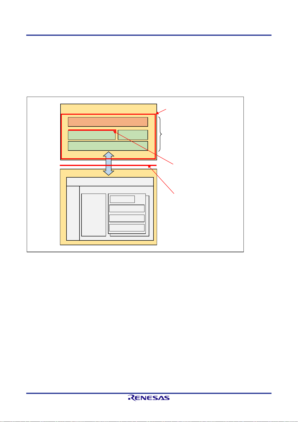
2.Software Structure
This sample program consists of the G3-PLC sample application unit, BSP unit, CPX3 SAP unit, and common
processing unit. The sample program is implemented on the host controller (microcontroller) and accesses to
the system block and the G3 block within R9A06G037 by using serial commands. By using API functions
provided by CPX3 SAP, it is possible to access each block within R9A06G037 without considering the serial
commands. All source codes for this sample program are open to the public. Figure 2-1 shows the software
configuration diagram. For details on specifications in red lines, refer to corresponding documents such as the
API specification and the serial command specification.
Figure 2-1 Software structure
Sample program
G3-PLC sample application
R9A06G037
UART I/F
G3 Block
G3
Controller
Open source codes
BSP
Sample API specification
Target of this document
System
Block
G3-PLC serial command specification
System block serial command
EAP Layer
ADP Sub Layer
MAC Sub Layer
PHY Layer
CPX3 SAP
Common part
Page 8
G3-PLC Sample Program User's Manual 2. Software Structure
R11UM0114EJ0101 Rev.1.01 Page 3 of 89
Jun. 19, 2019
RENESAS CONFIDENTIAL
2.1 Development Environment
2.1.1 Hardware
Table 2-1 shows evaluation boards supported in this sample program.
Table 2-1 List of evaluation board
Evaluation board
MCU
Note
J70D1/J70D2
RX631
RX631 represents R5F5631EDD FP.
(ROM:2Mbytes / RAM:128Kbytes / E2 Data Flash:32Kbytes)
Refer to the manual "GCPX3 Evaluation Kit J70D1" for board setting.
J80D1
RX651
RX651 represents R5F56519AD FP.
(ROM:1Mbytes / RAM:256Kbytes / Data Flash:none)
Refer to the manual "BCPX3 Evaluation Kit J80D1" for board setting.
J80D2
RL78G13
RL78G13 represents R5F100GLAFB.
(ROM:512Kbytes / RAM:32Kbytes / Data Flash:8Kbytes)
Refer to the manual "BCPX3 Evaluation Kit J80D2" for board setting.
2.1.2 Software
The projects on this sample program are operationally tested on the following integrated development
environments.
Table 2-2 List of integrated development environments
Integrated development environment
Details
e2studio
e2studio Ver 7.3.0
Compiler (RX631/RX651)
GCC for Renesas 4.8.4.201803-GNURX
Compiler (RL78G13)
CC-RL Ver 1.8.00
Page 9
G3-PLC Sample Program User's Manual 2. Software Structure
R11UM0114EJ0101 Rev.1.01 Page 4 of 89
Jun. 19, 2019
RENESAS CONFIDENTIAL
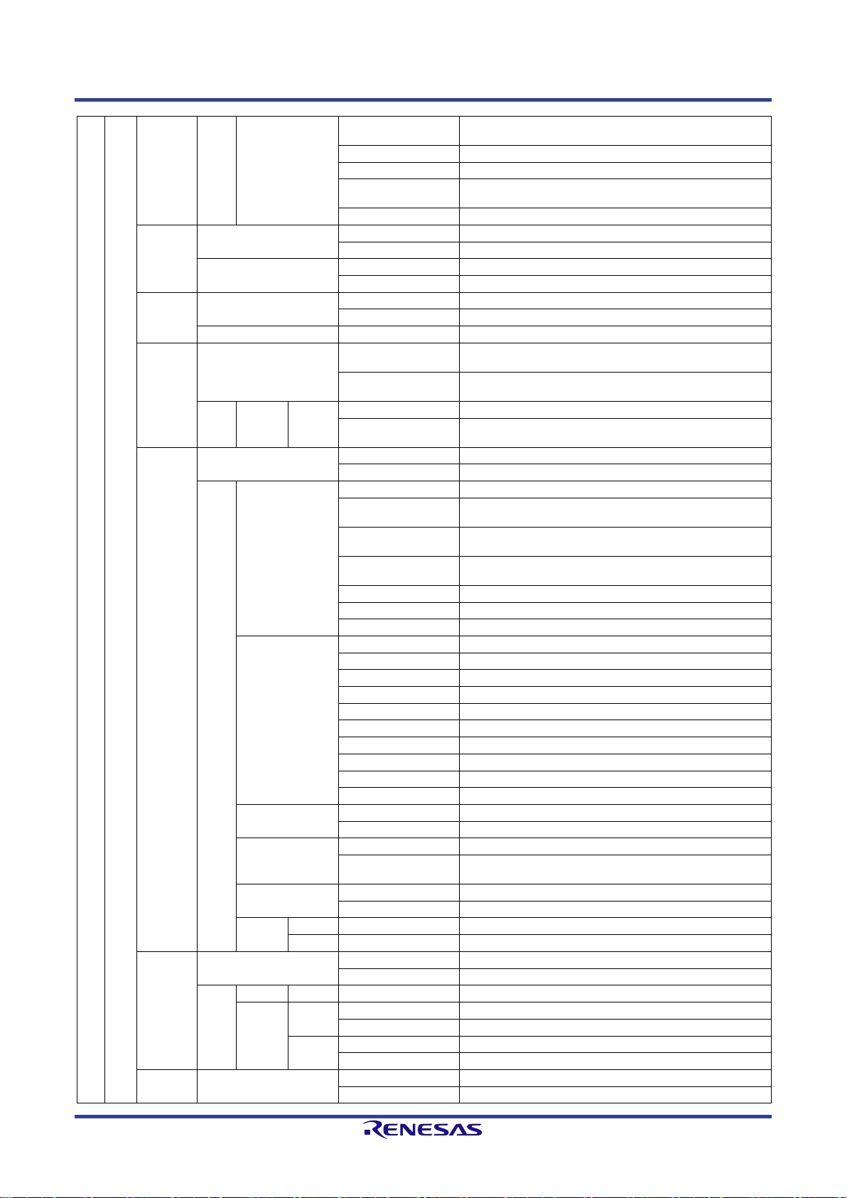
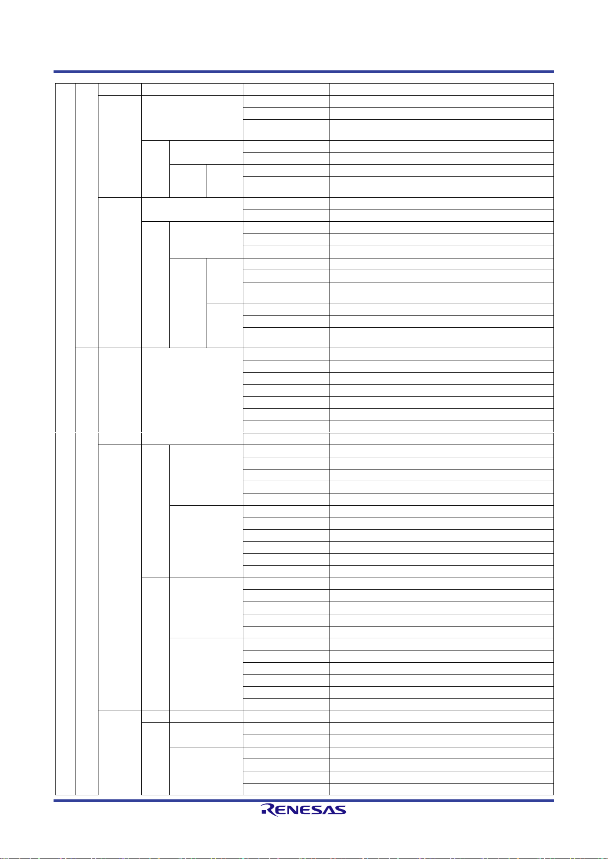
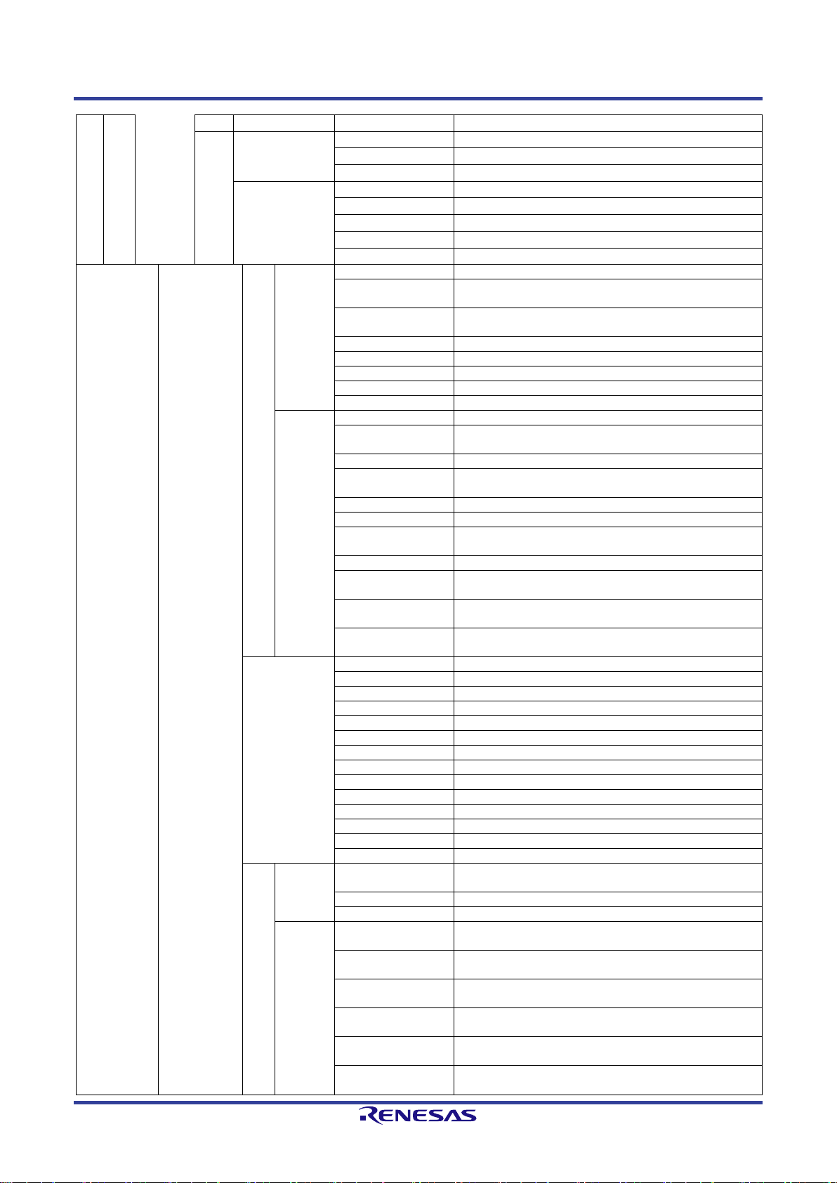
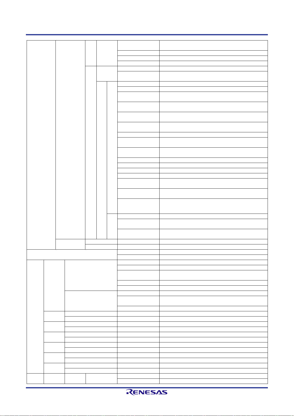
2.2 File structure
Table 2-3 shows file configuration of this sample application.
Table 2-3 File structure
Folder Name
File Name
Description
bsp
api
rl
inc
r_bsp_api.h
Header file for RL78 BSP API function
r_bsp_int.h
Header file for RL78 BSP interrupt function
src
r_bsp_api.c
RL78 BSP API function
rx
inc
r_bsp_api.h
RX BSP API function
src
r_bsp_api.c
RX BSP API function
rl_fit
r_bsp
platform.h
RL BSP common definition file
mcu
rl78g13
cpu.c
RL78-dedicated function
cpu.h
Header file for RL78-dedicated function
r_flash_rl
inc
r_flash_rl_if.h
Header file for FLASH API function open to the public
src
r_flash_rl.c
FLASH API function
r_flash_rl.h
Header file for FLASH API function
flash_ty
pe_4
r_flash_rl78.h
Header file for FLASH_TYPE_4 FLASH API function
incrl78
pfdl.h
Header file for flash data library(PicoFDL)
pfdl.inc
Flash data library(PicoFSL) include file
pfdl_types.h
Flash data library(PicoFDL) definition file
librl78
pfdl.lib
Flash data library(PicoFDL)
rx_fit
r_bsp
platform.h
RX BSP common definition file
mcu
all
r_bsp_common.c
MCU common function
r_bsp_common.h
Header file for MCU common function
rx631
cpu.c
RX631-dedicated function
cpu.h
Header file for RX631-dedicated function
locking.c
Header file for RX631 exclusive control function
locking.h
Header file for RX631 exclusive control function
mcu_clocks.c
RX631 clock control function
mcu_info.h
RX631 configuration
mcu_init.c
RX631 initial function
mcu_init.h
Header file for RX631 initial function
mcu_interrupts.c
RX631 interrupt function
mcu_interrupts.h
Header file for RX631 interrupt function
mcu_locks.c
RX631 exclusive control function by resource
mcu_locks.h
Header file for RX631exclusive control function by
resource
r_bsp.h
RX631 BSP header file
r_bsp_config.h
RX631 BSP configuration file
r_mcu_config.h
FLASH configuration when not using FIT
rx651
cpu.c
RX651-dedicated function
cpu.h
Header file for RX651-dedicated function
locking.c
RX651 exclusive control function
locking.h
Header file for RX651 exclusive control function
mcu_clocks.c
RX651 clock control function
mcu_info.h
RX651 configuration
mcu_init.c
RX651 initial function
mcu_init.h
Header file for RX651 initial function
mcu_interrupts.c
RX651 interrupt function
mcu_interrupts.h
Header file for RX651 interrupt function
mcu_locks.c
RX651 exclusive control function by resource
mcu_locks.h
Header file for RX651 exclusive control function by
resource
mcu_mapped_interr
upts.c
Interrupt function mapped to RX651
mcu_mapped_interr
upts.h
Header file for interrupt function mapped to RX651
Page 10
G3-PLC Sample Program User's Manual 2. Software Structure
R11UM0114EJ0101 Rev.1.01 Page 5 of 89
Jun. 19, 2019
RENESAS CONFIDENTIAL
mcu_mapped_interr
upts_private.h
Definition file for mapped interrupt function
r_bsp.h
Header file for RX651 BSP header file
r_bsp_config.h
RX651 BSP configuration file
r_bsp_interrupt_con
fig.h
Mapped interrupt function configuration
r_mcu_config.h
FLASH configuration when not using FIT
r_byteq
r_byteq_config.h
Queue configuration
r_byteq_if.h
Header file for external public queue API function
src
r_byteq.c
Queue API function
r_byteq_private.h
Queue API definition file
r_cmt
r_cmt_rx_config.h
CMT configuration
r_cmt_rx_if.h
Header file for external public CMT
src
r_cmt_rx.c
CMT API function
r_eeprom
_riic_rx
r_eeprom_riic_rx_co
nfig.h
EEPROM configuration
r_eeprom_riic_rx_if.
h
Header file for external public EEPROM API function
src
targets
eeprom
_riic
r_eeprom_riic_rx.c
EEPROM API function
r_eeprom_riic_rx_pr
ivate.h
EEPROM API definition file
r_flash_rx
r_flash_rx_config.h
FLASH configuration
r_flash_rx_if.h
Header file for external public FLASH API function
src
r_flash_fcu.c
FLASH_TYPE_3/FLASH_TYPE_4 common function
r_flash_fcu.h
Header file for FLASH_TYPE_3/FLASH_TYPE_4
common function
r_flash_group.c
FLASH_TYPE_1, FLASH_TYPE_3/FLASH_TYPE_4
common function
r_flash_group.h
Header file for FLASH_TYPE_1,
FLASH_TYPE_3/FLASH_TYPE_4 common function
r_flash_rx.c
FLASH API function
r_flash_rx.h
Header file for FLASH API function
r_flash_targets.h
FLASH API definition file
flash_type_1
r_codeflash.c
E2 code flash control function
r_codeflash.h
Header file for E2 code flash control function
r_codeflash_extra.c
Access window control function
r_codeflash_extra.h
Header file for access window control function
r_dataflash.c
E2 data flash control function
r_dataflash.h
Header file for E2 data flash control function
r_flash_common.h
Flash common definition file
r_flash_type1.c
FLASH_TYPE_1 API function
r_flash_type1_if.h
Header file for FLASH_TYPE_1 API function
r_flash_utils.c
FLASH API for RX11x series-dedicated section
flash_type_2
r_flash_type2.c
FLASH_TYPE_2 API function
r_flash_type2_if.h
Header file for FLASH_TYPE_2 API function
flash_type_3
r_flash_type3.c
FLASH_TYPE_3 API function
r_flash_type3_if.h
Header file for Header file for FLASH_TYPE_3 API
function
flash_type_4
r_flash_type4.c
FLASH_TYPE_4 API function
r_flash_type4_if.h
Header file for FLASH_TYPE_4 API function
targets
rx63n
r_flash_rx63n.h
RX631 FLASH definition file
rx65n
r_flash_rx65n.h
RX651 FLASH definition file
r_gpio
r_gpio_rx_config.h
GPIO configuration
r_gpio_rx_if.h
Header file for external public GPIO API function
src
r_gpio_rx.c
GPIO API function
targets
rx631
r_gpio_rx631.c
RX631 data file
r_gpio_rx631.h
RX631 definition file
rx651
r_gpio_rx651.c
RX651 data file
r_gpio_rx651.h
RX651 definition file
r_mpc
r_mpc_rx_config.h
MPC configuration
r_mpc_rx_if.h
Header file for external public MPC API function
Page 11
G3-PLC Sample Program User's Manual 2. Software Structure
R11UM0114EJ0101 Rev.1.01 Page 6 of 89
Jun. 19, 2019
RENESAS CONFIDENTIAL
src
r_mpc_rx.c
MPC API function
r_riic_rx
r_riic_rx_config.h
IIC configuration
r_riic_rx_if.h
Header file for external public IIC API function
r_riic_rx_pin_config.
h
PIN configuration for IIC use
src
r_riic_rx.c
IIC API function
r_riic_rx_private.h
IIC API definition file
targets
rx65n
r_riic_rx65n.c
RX651 IIC function
r_riic_rx65n_private.
h
RX651 definition file
r_sci
r_sci_rx_config.h
SCI configuration
r_sci_rx_if.h
Header file for external public SCI API function
src
r_sci_rx.c
SCI API function
r_sci_rx_platform.h
RX BSP SCI common definition
r_sci_rx_private.h
SCI API definition file
rx631
r_sci_rx631.c
RX631 SCI function
r_sci_rx631_data.c
RX631 data file
r_sci_rx631_private.
h
RX631 definition file
rx65n
r_sci_rx65n.c
RX651 SCI function
r_sci_rx65n_data.c
RX651 data file
r_sci_rx65n_private.
h
RX651 definition file
setu
p
ccrl
rl78g13
bin_include.asm
Binary file for include
cstart.asm
Startup routine
hwsetup.c
Hardware setting file
intprg.c
RL78G13 interrupt function
iodefine.h
RL78G13 register definition
machine.h
Header file for hardware control function
stkinit.asm
Stack area setting
vect.h
RL78G13 vector prototype
ccrx
rx631
inc
iodefine.h
RX631 I/O register definition
sbrk.h
Heap size definition
stacksct.h
Stack area setting
typedefine.h
Type definition
vect.h
RX631 vector prototype
src
dbsct.c
B/R section setting
hwsetup.c
Hardware setting file
intprg.c
RX631 interrupt function
resetprg.c
Startup routine
sbrk.c
Heap memory setting
vecttbl.c
RX631 vector table
rx651
inc
iodefine.h
RX651 ICU register definition
sbrk.h
Heap size definition
stacksct.h
Stack area setting
typedefine.h
Type definition
vect.h
RX651 vector prototype
src
dbsct.c
B/R section setting
hwsetup.c
Hardware setting file
intprg.c
RX651 interrupt function
resetprg.c
Startup routine
sbrk.c
Heap memory setting
vecttbl.c
RX651 vector table
gcc
rx631
inc
interrupt_handlers.h
Header file for RX631 interrupt function
iodefine.h
RX631 I/O register definition
machine.h
Header file for hardware control function
src
hardware_setup.c
Hardware setting file
interrupt_handlers.c
RX631 interrupt function
machine.c
Hardware control function
resetprg.c
Startup routine
Page 12
G3-PLC Sample Program User's Manual 2. Software Structure
R11UM0114EJ0101 Rev.1.01 Page 7 of 89
Jun. 19, 2019
RENESAS CONFIDENTIAL
vector_table.c
RX631 vector table
rx651
inc
interrupt_handlers.h
Header file for RX651 interrupt function
iodefine.h
RX651 I/O register definition
machine.h
Header file for hardware control function
src
hardware_setup.c
Hardware setting file
interrupt_handlers.c
RX651 interrupt function
machine.c
Hardware control function
resetprg.c
Startup routine
vector_table.c
RX651 vector table
cpx3_api
cpx3_sap
g3
inc
r_adp_binstruct.h
Header file for ADP layer binary command
r_c3sap_g3_buffsiz
e.h
Buffer and stack definition file
r_c3sap_g3_depend
.h
Environmental dependent part definition file
r_c3sap_g3_if.h
Header file for G3 layer API function
r_eap_binstruct.h
Header file for EAP layer binary command
r_g3ctrl_binstruct.h
Header file for G3 layer binary command
r_g3mac_binstruct.h
Header file for MAC layer binary command
r_g3_cmd.h
G3 block command ID definition file
src
r_c3sap_adp.c
ADP layer API function
r_c3sap_adp_conve
rt.c
ADP layer convert function
r_c3sap_eap.c
EAP layer API function
r_c3sap_eap_conve
rt.c
EAP layer convert function
r_c3sap_g3.c
G3 layer API function
r_c3sap_g3.h
G3 layer definition file
r_c3sap_g3ctrl_con
vert.c
G3 layer convert function
r_c3sap_g3mac.c
MAC layer API function
r_c3sap_g3mac_co
nvert.c
MAC layer convert function
r_c3sap_g3_convert
.h
Header file for G3 block convert function
r_c3sap_g3_depend
.c
API function for environment dependent G3 layer
inc
r_adp_sap.h
ADP layer definition file
r_adp_statistics.h
Definition file for ADP layer statistics information
r_c3sap_api.h
CPX3 SAP API definition file
r_c3sap_config.h
CPX3 SAP configuration
r_eap_sap.h
EAP layer definition file
r_eap_statistics.h
Definition file for EAP layer statistics information
r_g3mac_sap.h
MAC layer definition file
r_g3mac_statistics.h
Definition file for MAC layer statistics information
r_g3_api.h
Header file for G3 layer API header file
r_g3_sap.h
G3 layer definition file
r_lml_statistics.h
Definition file for LMAC layer statistics information
r_sys_api.h
Header file for SYSTEM layer API header file
r_sys_sap.h
SYSTEM layer definition file
r_uif_statistics.h
Definition file for UART-IF statistics information
sys
inc
r_c3sap_sys_depen
d.h
Definition file for environment dependent system block
r_c3sap_sys_if.h
Header file for system block API function
r_constants.h
Definition file(handler) for SAP layer constant
src
r_c3sap_sys.c
System block API function
(not depending on environment)
r_c3sap_sys.h
Header file for system block API function(not
depending on environment )
r_c3sap_sys_conve
rt.c
System block convert function
r_c3sap_sys_conve
rt.h
Header file for system block convert function
r_c3sap_sys_depen
d.c
System block API function
(environment dependent)
r_c3sap_sys_thread
.c
CPX3 SAP pseudo thread function
Page 13
G3-PLC Sample Program User's Manual 2. Software Structure
R11UM0114EJ0101 Rev.1.01 Page 8 of 89
Jun. 19, 2019
RENESAS CONFIDENTIAL
r_c3sap_sys_thread
.h
Header file for CPX3 SAP pseudo thread function
r_c3sap_sys_ver.h
CPX3 SAP version definition file
r_sys_binstruct.h
Header file for system block binary command
r_sys_cmd.h
System block command ID definition file
uif
inc
r_uif_sap_if.h
Header file for external public UIF API function
r_uif_thread_if.h
Header file for UIF API function
(IF/core)
src
core
r_uif_base.h
UIF core-based header file
r_uif_base_param.h
UIF core parameter definition file
r_uif_buff_declared.
c
UIF core buffer management function
r_uif_buff_declared.
h
Header file for UIF core buffer management function
r_uif_data_manage.
c
UIF core data management function
r_uif_data_manage.
h
Header file for UIF core data management function
r_uif_hdlc.h
HDLC packet definition file
r_uif_hdlc_process.
c
HDLC packet control function
r_uif_hdlc_process.
h
Header file for HDLC packet control
r_uif_intc.c
UIF transfer interrupt function
r_uif_intc.h
Header file for UIF transfer interrupt function
r_uif_rx_process.c
UIF reception control function
r_uif_rx_process.h
Header file for UIF reception control function
r_uif_statistics_inter
nal.h
UIF statistics information internal definition file
r_uif_tx_process.c
UIF transmission
control function
r_uif_tx_process.h
Header file for UIF
transmission control
function
if
r_c3sap_uif.c
UIF API function
r_c3sap_uif_drv.c
Part function within
UIF
r_c3sap_uif_drv.h
Header file for part
function within UIF
fw_download
inc
r_fw_download.h
Header file for R9A06G037 boot function
src
r_fw_download.c
R9A06G037 boot function
cpx3_fw
cpx3_fw_release.bin
Binary file for R9A06G037 firmware
cpx3_fw_release.h
Header file for R9A06G037 firmware
extern
common
inc
r_byte_swap.h
Header file for array/integer data convert function
r_config.h
Sample program setting configuration
r_io_vec.h
Header file for function connecting distributed data to
1 stream
r_mem_tools.h
Header file for memory tool function
r_typedefs.h
Type definition
src
r_byte_swap.c
Array/Integer data convert function
r_io_vec.c
Header file for function connecting distributed data to
1 stream
r_mem_tools.c
Memory tool function
crc
inc
r_crc32_api.h
Header file for CRC32 API function
src
r_crc32_api.c
CRC32 API function
led
inc
r_led_api.h
Header file for LED control API function
src
r_led_api.c
LED control API function
memory
inc
r_memory_api.h
Header file for memory management API function
src
r_memory_api.c
Memory management API function
queue
inc
r_queue_api.h
Header file for queue management API function
src
r_queue_api.c
Queue management API function
stdio
inc
r_stdio_api.h
Header file for console I/O API function
src
r_stdio_api.c
Console I/O API function
timer
inc
r_timer_api.h
Header file for software timer API function
src
r_timer_api.c
Software timer API function
project
e2s
rl78g13
G3PLC
.Certificationlinker
Linker file for certification build
.cproject
Tool chain setting file
Page 14
G3-PLC Sample Program User's Manual 2. Software Structure
R11UM0114EJ0101 Rev.1.01 Page 9 of 89
Jun. 19, 2019
RENESAS CONFIDENTIAL
.Demolinker
Linker file for demo build
.info
Development environment information
.project
Project setting file
.Releaselinker
Linker file for release build
G3PLC
Release.launch
Debug setting file
makefile.init
Makefile initial setting
rx631
G3PLC
.Certificationlinker
Linker file for certification build
.cproject
Tool chain setting file
.Demolinker
Linker file for demo build
.info
Development environment information
.project
Project setting file
.Releaselinker
Linker file for release build
G3PLC
Release.launch
Debug setting file
makefile.init
Makefile initial setting
rx651
G3PLC
.Certificationlinker
Linker file for certification build
.cproject
Tool chain setting file
.Demolinker
Linker file for demo build
.info
Development environment information
.project
Project setting file
.Releaselinker
Linker file for release build
G3PLC
Release.launch
Debug setting file
makefile.init
Makefile initial setting
sample_app
extern
flash
inc
r_demo_nvm_proce
ss.h
Header file for NVM management function
r_demo_print.h
Header file for string operation function
r_demo_status2text.
h
Header file for status information and string convert
function
r_flash_lib.h
Header file for FLASH driver wrapper function
r_flash_usage_map.
h
Macro definition file for address acquisition in NVM
area
src
r_demo_nvm_proce
ss.c
NVM management function
r_demo_print.c
String operation function
r_demo_status2text.
c
Status information and string convert function
r_flash_lib.c
FLASH driver wrapper function
ipv6
inc
r_check_sum.h
Header file for checksum calculation function
r_icmp_v6.h
icmp v6 definition file
r_ipv6_headers.h
IPv6 packet definition file
r_udp_headers.h
UDP packet definition file
src
r_check_sum.c
Checksum calculation function
r_icmp_v6.c
ICMP v6 packet control function
r_ipv6_headers.c
IPv6 packet control function
r_udp_headers.c
UDP packet control function
inc
r_cpx3_scramble_m
atrix.h
Encryption matrix definition file
r_demo_api.h
Header file for wrapper function of calling CPX3
SAP(MAC,ADP)
r_demo_app.h
Header file for main application
r_demo_app_eap.h
Header file for CPX3 SAP wrapper function (EAP)
r_demo_app_thread
.h
Header file for application pseudo thread
r_demo_app_ver.h
Version definition file of sample application
r_demo_common.h
Header file for IPv6 packet control API function
r_demo_config.h
Header file for configuration of application
r_demo_ib_access.
h
Header file for IB access API function
r_demo_main.h
Header file for main function
r_demo_metric_com
putation.h
Header file for link cost calculation
r_demo_os_wrapper
.h
Header file for OS wrapper function
r_demo_parameters
.h
Configuration parameter definition file
Page 15
G3-PLC Sample Program User's Manual 2. Software Structure
R11UM0114EJ0101 Rev.1.01 Page 10 of 89
Jun. 19, 2019
RENESAS CONFIDENTIAL
r_demo_statistics.h
Header file for statistics information /log acquisition
r_demo_sys.h
Header file for system menu API function
r_demo_tools.h
Header file for string control API function
src
main.c
Main function
r_demo_api.c
CPX3 SAP wrapper function (MAC,ADP)
r_demo_app.c
Main function for sample application
r_demo_app_thread
.c
Pseudo thread for applications
r_demo_bootstrap.c
Network start function
r_demo_common.c
API function for IPv6 packet control
r_demo_config.c
API function for configuration information
management
r_demo_eap.c
CPX3 SAP wrapper function (EAP)
r_demo_g3_cb.c
CPX3 SA callback function
r_demo_ib_access.c
API function for IB access
r_demo_main.c
Sample application start
r_demo_metric_com
putation.c
API function for link cost calculation
r_demo_os_wrapper
.c
OS wrapper function
r_demo_parameters
.c
Configuration parameter
r_demo_statistics.c
API function for statistics information / log acquisition
r_demo_sys.c
API function for system menu
r_demo_sys_cb.c
Callback function for system menu
r_demo_tools.c
String control API function
Page 16
G3-PLC Sample Program User's Manual 3. Project Settings
R11UM0114EJ0101 Rev.1.01 Page 11 of 89
Jun. 19, 2019
RENESAS CONFIDENTIAL
3.Project Settings
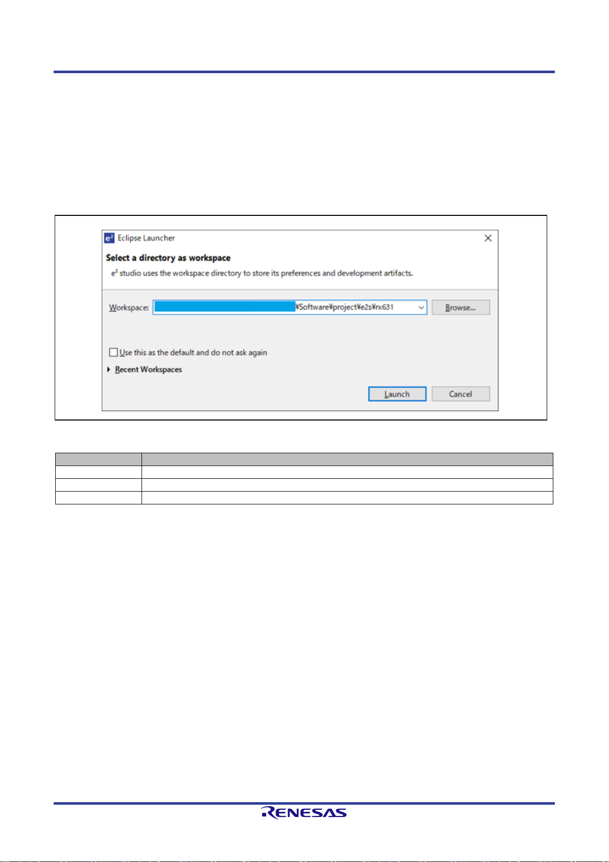
3.1 Start e2studio
3.1.1 Workspace settings
Start e2studio and set up the following workspace. For this sample program, a project is prepared for each
evaluation board.
Figure 3-1 Select workspace
Evaluation board
Workspace path
J70D1/J70D2
(Installed directory path)\Software\project\e2s\rx631
J80D1
(Installed directory path)\Software\project\e2s\rx651
J80D2
(Installed directory path)\Software\project\e2s\rl78g13
Page 17
G3-PLC Sample Program User's Manual 3. Project Settings
R11UM0114EJ0101 Rev.1.01 Page 12 of 89
Jun. 19, 2019
RENESAS CONFIDENTIAL
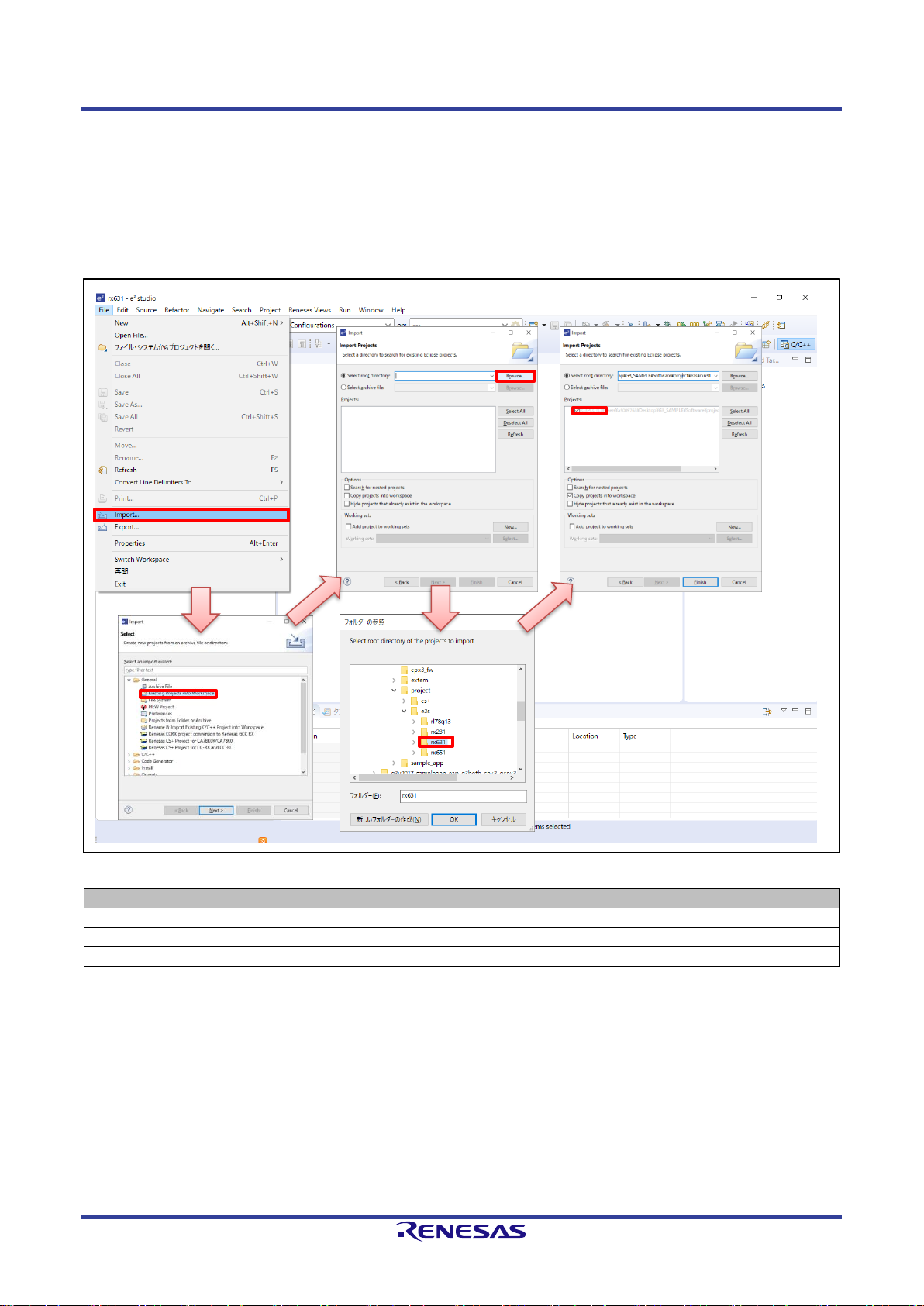
3.1.2 Import project
The project will be imported by the following procedure.
1. File -> Import
2. Existing Project into Workspace
3. Set the following path in the root directory
4. Select G3PLC
Figure 3-2 Import Project
Evaluation board
Root directory path
J70D1/J70D2
(Installed directory path)\Software\project\e2s\rx631
J80D1
(Installed directory path)\Software\project\e2s\rx651
J80D2
(Installed directory path)\Software\project\e2s\rl78g13
G3PLC
[1]
[2]
[3]
[4]
Page 18
G3-PLC Sample Program User's Manual 3. Project Settings
R11UM0114EJ0101 Rev.1.01 Page 13 of 89
Jun. 19, 2019
RENESAS CONFIDENTIAL
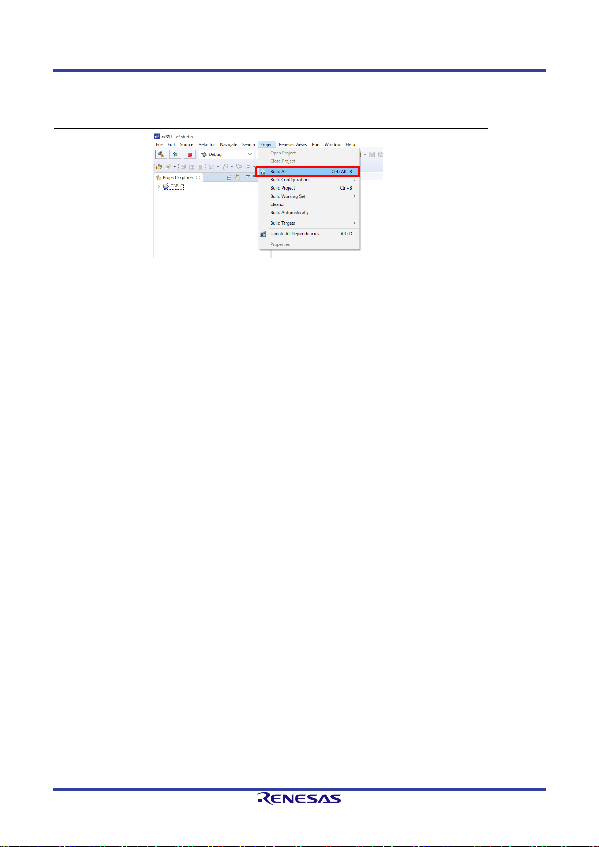
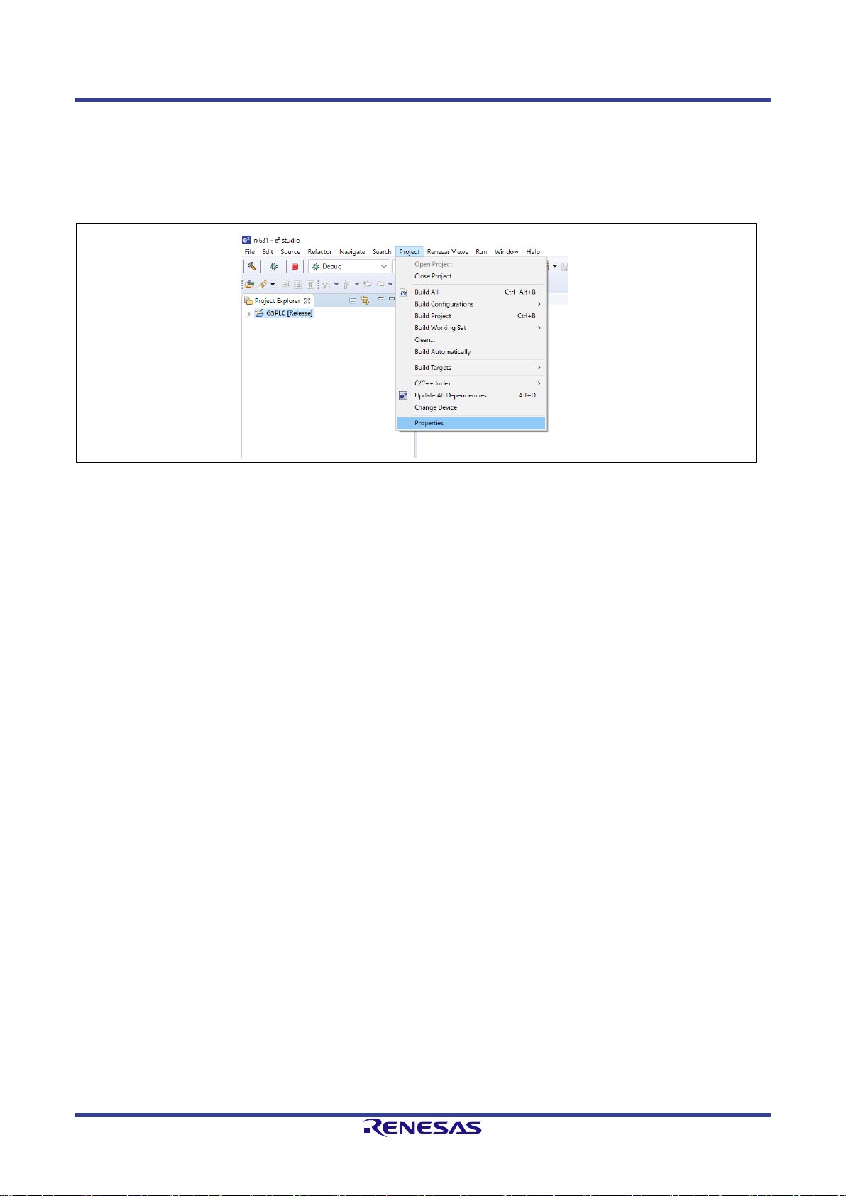
3.1.3 Building project
Select Project -> Build All and do the build.
Figure 3-3 Build project
Page 19
G3-PLC Sample Program User's Manual 3. Project Settings
R11UM0114EJ0101 Rev.1.01 Page 14 of 89
Jun. 19, 2019
RENESAS CONFIDENTIAL
3.2 Built Environment
There are 3 types of built environments for 1 project, and the parameter to be set can be switched at startup.
The Macro definitions to be defined vary depending on the built environment. For some built environments,
the setting can be changed by DipSw. The DipSw-bit is assigned as PORT_ID and managed by common
control as DipSw allocation varies depending on the evaluation board type. Table 3-1 shows the relationship
between DipSw and PORT_ID. Refer to the start guide (G3-PLC Sample Application Start Guide for GCPX3
board) for functions in detail.
Table 3-1 DipSw setting
PORT ID
J70D1/J70D2
J80D1/J80D2
Function
SW
No
SW
No
PORT_ID_AUTO_MODE
SW1
1
SW9
1
Application mode (Refer to 3.3) setting
PORT_ID_CERT_MODE
2
2
Application mode (Refer to 3.3) setting
- 3 3
-
- 4 4
-
PORT_ID_ROUTE_TYPE
5
SW8
1
Route type setting
PORT_ID_BANDPLAN_1
6
2
BandPlan setting
PORT_ID_BANDPLAN_0
7
3
PORT_ID_DEVICE_TYPE
8
4
Device type (Coordinator/Peer) setting
This program provides 3 types of built environments.
・Release build :When ”Release” is selected for the build configuration of the development
environment. This manual is based on this built environment if not explicitly stated.
The parameters to be set at startup will be reflected by the DipSw setting.
・Demo build :When “Demo” is selected for the build configuration of the development environment.
The parameters will be reflected based on data recorded in NVM. The memory used
for NVM varies depending on the evaluation board, yet NVM is accessed from via the
flash control unit(Chapter 4.1.5) in this program. The following macro is defined in the
project file. R_DEFINE_APP_MODE=1
・Certification mode :When “Certification” is selected for the build configuration of the development
environment. This configuration is used to execute the authentication test by
connecting to an authentication device supporting G3. After power supply, the sample
application will automatically work and start test communication with the authentication
device. This mode is driven by the G3 authentication parameters, and therefore it is
not possible to communicate with the evaluation board running on the Release/Demo
build. The following macro is defined in the project file. R_DEFINE_APP_MODE=2
Details on macros are explained in Chapter 3.3.
Page 20
G3-PLC Sample Program User's Manual 3. Project Settings
R11UM0114EJ0101 Rev.1.01 Page 15 of 89
Jun. 19, 2019
RENESAS CONFIDENTIAL
3.3 Macro Definition
This section describes the macro definitions to be set on the project.
3.3.1 R_BOARD_TYPE
This is the definition for determining the evaluation board that will work the sample application.
Table 3-2 R_BORAD_TYPE description
Define name
Value
Description
R_BOARD_NOT_SET
0
Do not use
R_BOARD_G_CPX3
5
J70/D1 and J70/D2 evaluation board.
R_BOARD_J80D1
9
J80/D1 evaluation board.
R_BOARD_J80D2
10
J80/D2 evaluation board.
3.3.2 R_DEFINE_APP_MODE
By defining this macro, it is possible to change the parameter to be set at startup . Table 3-3 shows setting
values for this macro.
Table 3-3 R_DEFINE_APP_MODE setting value
Definition
Value
R_DEMO_APP_MODE_NORMAL
0u
R_DEMO_APP_MODE_DEMO
1u
R_DEMO_APP_MODE_CERT
2u
Table 3-4 shows parameters to be set at startup.
Table 3-4 Relationship between R_DEFINE_APP_MODE and parameters
Parameter
R_DEFINE_APP_MODE
R_DEMO_APP_MODE_NORM
AL
R_DEMO_APP_MODE_DEMO
R_DEMO_APP_MODE_CERT
bandPlan
Select by DipSw
(PORT_ID_BANDPLAN_0,
PORT_ID_BANDPLAN_1)
Data value recorded in NVM
R_G3_BANDPLAN_
CENELEC_A when no effective
data exist
Select by DipSw
(PORT_ID_BANDPLAN_0,
PORT_ID_BANDPLAN_1)
deviceType
Select by DipSw
(PORT_ID_DEVICE_TYPE)
Data value recorded in NVM
R_ADP_DEVICE_
TYPE_PEER when no effective
data exist
Select by DipSw
(PORT_ID_DEVICE_TYPE)
startMode
(appMode)
*1
Select by DipSw
(PORT_ID_AUTO_MODE,
PORT_ID_CERT_MODE)
Data value recorded in NVM
R_DEMO_MODE_CUI when no
effective data exist
Set R_DEMO_MODE_CERT
routeType
Select by DipSw
(PORT_ID_ROUTE_TYPE)
Data value recorded in NVM
R_G3_ROUTE_TYPE_NORMA
L when no effective data exist
R_G3_ROUTE_TYPE_JP_B for
ARIB depending on bandPlan
R_G3_ROUTE_TYPE_NORMA
L for other than the above
*1 application mode
Page 21
G3-PLC Sample Program User's Manual 3. Project Settings
R11UM0114EJ0101 Rev.1.01 Page 16 of 89
Jun. 19, 2019
RENESAS CONFIDENTIAL
The sample program defines the following 3 modes as an application mode.
・CUI mode(R_DEMO_MODE_CUI) :Coordinator or Peer selectable by the user.
・AUTO mode(R_DEMO_MODE_AUTO) :Start operation according to PORT_ID_DEVICE_TYPE.
・CERT mode(R_DEMO_MODE_CERT) :Start test communication with the authentication device by
automatically starting the sample application.
3.3.3 R_RL78_PLC
This macro definition is used to switch the process depending on the microcontroller type (RL78/RX series).
Table 3-5 shows parameters to be changed by this macro definition.
Table 3-5 Parameter to be changed by the definition R_RL78_PLC.
Parameter
Defined (RL78G13)
Not defined (RX)
Far modifier
Yes
No
Timer
16-bit timer
8-bit timer and
compare match timer
The number of stages in the queue
3 8 Data size to be saved in 1 stage of the queue
1400 bytes
1500 bytes
Refer to 4.5.2 for the queue usage.
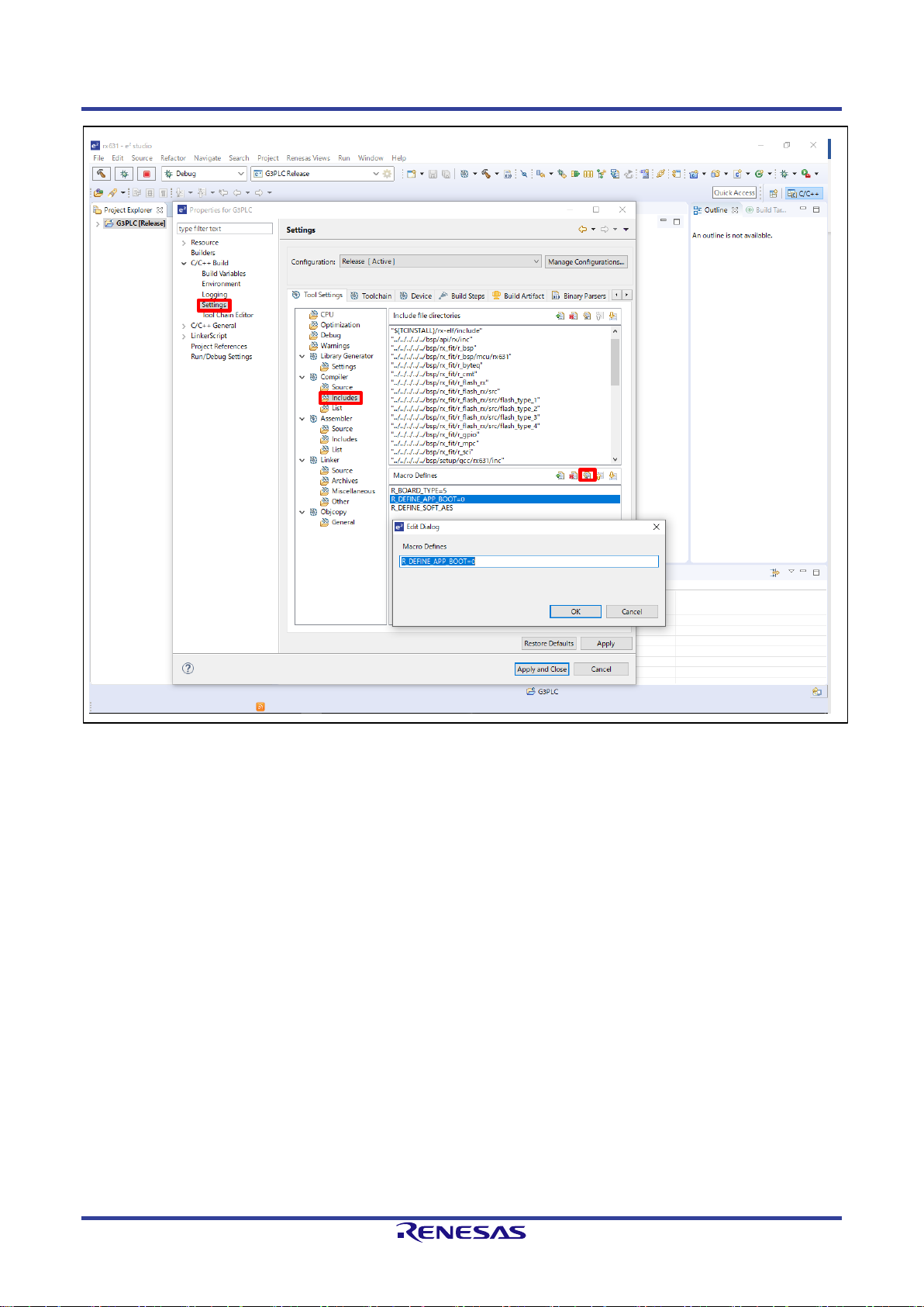
3.3.4 R_DEFINE_APP_BOOT
This macro definition is used to switch the CPX3 boot mode. Table 3-6 shows setting values for this macro.
Table 3-6 R_DEFINE_APP_BOOT setting value
Definition
Value
R_DEMO_APP_UART_BOOT
0u
R_DEMO_APP_SROM_BOOT
1u
Table 3-7 shows parameters to be changed by this macro definition.
Table 3-7 Parameter to be changed by definition R_DEFINE_APP_BOOT
Parameter
R_DEMO_APP_UART_BOOT
R_DEMO_APP_SROM_BOOT
R_DEFINE_APP_BOOT
Boot by downloading FW via UART from
the host microcontroller.
Boot by downloading FW saved in the
serial flash memory connecting to CPX3.
Page 22
G3-PLC Sample Program User's Manual 3. Project Settings
R11UM0114EJ0101 Rev.1.01 Page 17 of 89
Jun. 19, 2019
RENESAS CONFIDENTIAL
In the e2studio project, the procedure to change the macro definition is as follows.
1. Project -> Properties
2. C++ Build -> Settings
3. Tool Settings Tab-> Compiler -> Includes
4. Change Macro define value
Figure 3-4 Change macro definition (1/2)
Page 23
G3-PLC Sample Program User's Manual 3. Project Settings
R11UM0114EJ0101 Rev.1.01 Page 18 of 89
Jun. 19, 2019
RENESAS CONFIDENTIAL
Figure 3-5 Change macro definition (2/2)
Page 24
G3-PLC Sample Program User's Manual 3. Project Settings
R11UM0114EJ0101 Rev.1.01 Page 19 of 89
Jun. 19, 2019
RENESAS CONFIDENTIAL
3.4 Memory Map
The section layouts for each MCU are shown below.
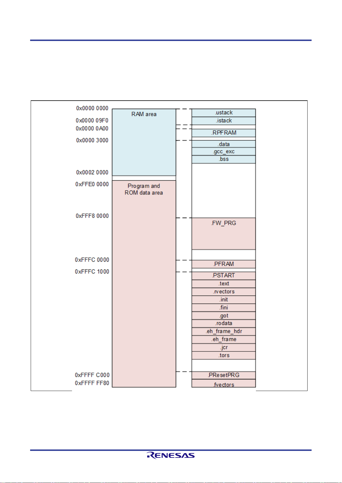
3.4.1 RX631
Figure 3-6 shows the section layout for the sample program and Table 3-8 describes each section in detail.
Figure 3-6 Section layout (RX631(R5F5631EDxFP))
Page 25

G3-PLC Sample Program User's Manual 3. Project Settings
R11UM0114EJ0101 Rev.1.01 Page 20 of 89
Jun. 19, 2019
RENESAS CONFIDENTIAL
Table 3-8 Section list (RX631)
Section
Section start address
Description
.ustack
0x00000000
User stack section.
Allocation size is 0 as it is not used.
.istack
0x000009F0
Interrupt stack section.
.RPFRAM
0x00000A00
Section for expanding sections of the PFRAM section to RAM.
.data
0x00003000
Section for variables with the initial value.
.gcc_exc
Located after.data
Section for GCC exceptions.
.bss
Located after.gcc_exc
Section for variables without the initial value.
.FW_PRG
0xFFF80000
Section for CPX3 FW
.PFRAM
0xFFFC0000
Section to mapping Flash driver to operate in RAM
.PSTART
0xFFFC1000
Section for startup code.
.text
Located after .PSTART
Section for program codes.
.rvectors
Located after .text
Section for variable (interrupt) vector table.
.init
Located after.rvectors
Section for initial setting codes.
.finit
Located after.init
Section for end codes.
.got
Located after.finit
Section for global offset table.
.rodata
Located after.got
Section for ROM data.
.eh_frame_hdr
Located after.rodata
Section for exceptional handler data.
.eh_frame
Located after.eh_frame_hdr
Section for exceptional handler frame.
.jcr
Located after.eh_frame
Java section.
.tors
Located after.jcr
Section for C++ constructor/ destructor.
.PResetPRG
0xFFFFC000
Section assigned with the function to be executed after reset.
.fvectors
0xFFFFFF80
Section for fixed(exceptional)vector table.
Page 26
G3-PLC Sample Program User's Manual 3. Project Settings
R11UM0114EJ0101 Rev.1.01 Page 21 of 89
Jun. 19, 2019
RENESAS CONFIDENTIAL
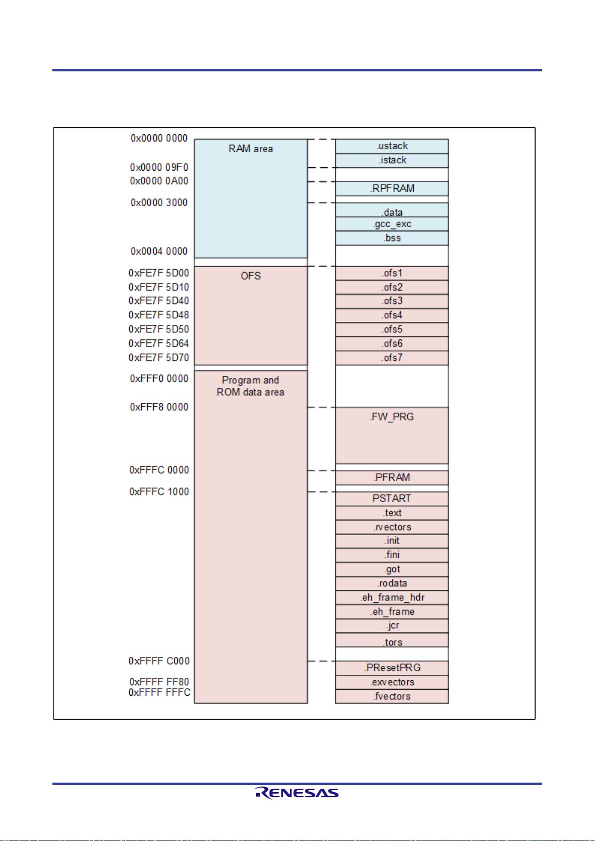
3.4.2 RX651
Figure 3-7 shows the section layout for the sample program, and Table 3-9 describes each section in detail.
Figure 3-7 Section layout (RX651(R5F56519AxFP))
Page 27

G3-PLC Sample Program User's Manual 3. Project Settings
R11UM0114EJ0101 Rev.1.01 Page 22 of 89
Jun. 19, 2019
RENESAS CONFIDENTIAL
Table 3-9 Section list (RX651)
Section
Section start address
Description
.ustack
0x00000000
User stack section.
Allocation size is 0 as it is not used.
.istack
0x000009F0
Interrupt stack section.
.RPFRAM
0x00000A00
Section for expanding sections of the PFRAM section to RAM.
.data
0x00003000
Section for variables with the initial value.
.gcc_exc
Located after.data
Section for GCC exceptions.
.bss
Located after.gcc_exc
Section for variables without the initial value.
.ofs1
0xFE7F5D00
Option setting memory section.
.ofs2
0xFE7F5D10
Option setting memory section.
.ofs3
0xFE7F5D40
Option setting memory section.
.ofs4
0xFE7F5D48
Option setting memory section.
.ofs5
0xFE7F5D50
Option setting memory section.
.ofs6
0xFE7F5D64
Option setting memory section.
.ofs7
0xFE7F5D70
Option setting memory section.
.FW_PRG
0xFFF80000
Section for CPX3 FW
.PFRAM
0xFFFC0000
Section to mapping Flash driver to operate in RAM
.PSTART
0xFFF00000
Section for startup code.
.text
Located after .PSTART
Section for program codes.
.rvectors
Located after .text
Section for variable (interrupt) vector table.
.init
Located after.rvectors
Section for initial setting codes.
.finit
Located after.init
Section for end codes.
.got
Located after.finit
Section for global offset table.
.rodata
Located after.got
Section for ROM data.
.eh_frame_hdr
Located after.rodata
Section for exceptional handler data.
.eh_frame
Located after.eh_frame_hdr
Section for exceptional handler frame.
.jcr
Located after.eh_frame
Java section.
.tors
Located after.jcr
Section for C++ constructor/ destructor
.PResetPRG
0xFFFFC000
Section assigned with the function to be executed after reset.
.exvectors
0xFFFFFF80
Section for exceptional vector table.
.fvectors
0xFFFFFFFC
Section for fixed vector table.
Page 28
G3-PLC Sample Program User's Manual 3. Project Settings
R11UM0114EJ0101 Rev.1.01 Page 23 of 89
Jun. 19, 2019
RENESAS CONFIDENTIAL
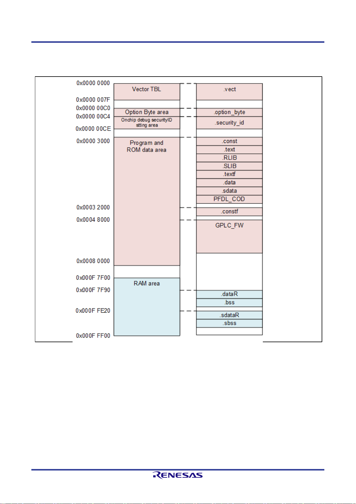
3.4.3 RL78G13
Figure 3-8 shows the section layout for the sample program, and Table 3-10 describes each section in detail.
Figure 3-8 Section layout (RL78G13(R5F100GL))
Page 29

G3-PLC Sample Program User's Manual 3. Project Settings
R11UM0114EJ0101 Rev.1.01 Page 24 of 89
Jun. 19, 2019
RENESAS CONFIDENTIAL
Table 3-10 Section list (RL78G13)
Section
Section start address
Description
.vect
0x00000000
Section for vector table.
.option_byte
0x000000C0
Section for optional bytes.
.security_id
0x000000C4
Section for security ID.
.const
0x0000300
Section for ROM data(near area allocation).
.text
Located after .const
Section for program codes(near area allocation).
.RLIB
Located after.text
Section for Runtime/Library codes.
.SLIB
Located after.RLIB
Section for standard library codes.
.textf
Located after.SLIB
Section for program codes(far area allocation).
.data
Located after.textf
Section for variables with the near initial value.
.sdata
Located after.data
Section for variables with the initial value( variables of saddr
allocation ).
.PFDL_COD
Located after.sdata
Section for data flash library codes.
.constf
0x00032000
Section for ROM data(far area allocation).
.GPLC_FW
0x00048000
Section for CPX3 FW.
.dataR
0x000F7F90
Section to be mapped from ROM to RAM.
.bss
Located after.dataR
Section for variables without the initial value ( near area
allocation).
.sdataR
0x000FFE20
Section to be mapped from ROM to RAM.
.sbss
Located after.sdataR
Section for variables without the initial value(variables of saddr
allocation ).
Page 30
G3-PLC Sample Program User's Manual 4. Sample Program
R11UM0114EJ0101 Rev.1.01 Page 25 of 89
Jun. 19, 2019
RENESAS CONFIDENTIAL
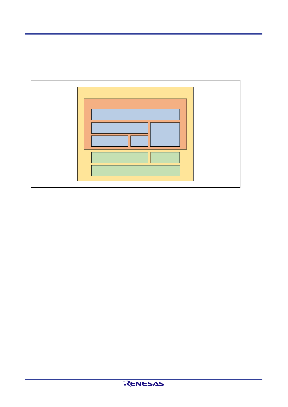
4.Sample Program
This sample program consists of the G3-PLC sample application unit, BSP unit ,CPX3 SAP unit, and common
processing unit and operates on the framework using timer interrupts after startup sequence initialization.
Refer to Chapter 4.5 for the framework in detail.
Figure 4-1 Sample program block diagram
4.1 G3-PLC Sample Application
The G3-PLC sample application consists of process blocks from the command processing unit,G3 processing
unit,G3 API wrapper unit,IPV6 unit and flash control unit. The overview of each process block is as below:
(1) Command processing unit :provides user interface(CUI) to control sample applications.
(2) G3 processing unit :provides functions used for G3-PLC communication process.
(3) G3 API wrapper :provides the wrapper layer to convert CPX3 SAP API from asynchronous to
synchronous.
(4) IPV6 unit :provides function to generate/analyze IPV6 packets.
(5) Flash control unit :provides function to manage communication parameters.
The sample application performs initialization in the main function and calls the function R_DEMO_Main().
The function R_DEMO_Main() executes command process and G3 process for user interfaces. Figure 4-2
and Figure 4-3 show process flows of the main function and the function R_DEMO_Main() respectively.
Sample program
G3-PLC sample application
Command processing unit
G3 processing unit
CPX3 SAP
G3 API wrapper
BSP
IPV6
Flash control
unit
Common
processing
Page 31

G3-PLC Sample Program User's Manual 4. Sample Program
R11UM0114EJ0101 Rev.1.01 Page 26 of 89
Jun. 19, 2019
RENESAS CONFIDENTIAL
Figure 4-2 Main function process flow
(1) Preform initialization to control LED on the evaluation board
(2) Set the CPX3FW boot mode(Setting CPX3 BOOT0 terminal level ).
(3) Perform standard I/O initialization such as terminal software(PC) and debug output(PC) etc.
(4) Initialize the software timer.
(5) Execute demo application main process.
Page 32

G3-PLC Sample Program User's Manual 4. Sample Program
R11UM0114EJ0101 Rev.1.01 Page 27 of 89
Jun. 19, 2019
RENESAS CONFIDENTIAL
Figure 4-3 The function R_DEMO_Main process flow
(1) Initialize CPX3 SAP and boot CPX3.
(2) Initialize the flash driver.
(3) Startup the thread for applications.
(4) Check the validity of the NVM area (check presence/absence of SyncWord). When it is judged as invalid,
the default value will be written into the NVM area.
(5) Set the communication parameter. Note that the setting value varies depending on the built environment.
Refer to 4.1.1.1 for details.
(6)(7) When the application mode (appMode) is AUTO mode/CERT mode, the function R_DEMO_App() will
be executed. For the CUI mode, the function R_DEMO_AppMainMenu() will be executed.
Page 33

G3-PLC Sample Program User's Manual 4. Sample Program
R11UM0114EJ0101 Rev.1.01 Page 28 of 89
Jun. 19, 2019
RENESAS CONFIDENTIAL
4.1.1 Application Control Parameters
The sample application has control parameters such as table size and LQI threshold values retained internally
for G3-PLC communication. It also has management information as a configuration such as whether operating
on Coordinator or Peer and BandPlan etc.
4.1.1.1 Control Parameters
There are 3 types of control parameters for CPX3 or for applications. By defining R_PROFILE_DEFAULT,
R_PROFILE_METERING or R_PROFILE_NO_HOP as a header file r_demo_parameters.h, the parameter
setting value changes partly. In the sample application, R_PROFILE_METERING is defined for parameter
setting for meter applications. For no hop application define R_PROFILE_NO_HOP and the other application
define R_PROFILE_DEFAULT. Table 4-1 and Table 4-2 show parameters to be set for CPX3. Table 4-3 show
parameters used only for applications.
Table 4-1 CPX3 setting parameters(when r_demo_parameters.h: Common profile)
Parameter
Definition
Value
Neigbour table size
R_DEMO_G3MAC_NEIGBOUR_TABL
E_SIZE
500
Device table size
R_DEMO_G3MAC_DEVICE_TABLE_S
IZE
500
adpdBuffNum
R_DEMO_ADP_ADPD_DATA_QUEUE
_SIZE
2
Routing table size
R_DEMO_ADP_ROUTING_TABLE_SI
ZE
500
The maximum PAN descriptor value
R_DEMO_ADP_MAX_PAN_DESCRIP
TORS
64
LBP buffer size
R_DEMO_EAP_LBP_BUFF_SIZE
8
Client Info table size
R_DEMO_EAP_CINFO_TABLE_SIZE
64
Interval for frame counter indications
R_FRAMECOUNT_INTERVAL
0x100
SNR offset (CENELEC-A)
R_VAL_MAC_OFFSET_SNR_CA
0xFD
SNR offset (ARIB)
R_VAL_MAC_OFFSET_SNR_ARIB
0xFA
SNR offset (FCC)
R_VAL_MAC_OFFSET_SNR_FCC
0xFA
TMR Indication enable/disable setting
R_VAL_MAC_TMR_IND_ENABLE
R_TRUE
Route Indication enable/disable setting
R_VAL_ADP_ROUTE_IND_ENABLE
R_TRUE
RREP Indication enable/disable setting
R_VAL_ADP_RREP_IND_ENABLE
R_TRUE
SATT enable / disable setting
R_VAL_PHY_SATT_CTRL_DISABLE
R_FALSE
Page 34

G3-PLC Sample Program User's Manual 4. Sample Program
R11UM0114EJ0101 Rev.1.01 Page 29 of 89
Jun. 19, 2019
RENESAS CONFIDENTIAL
Table 4-2 CPX3 setting parameters(when r_demo_parameters.h: Individual profile )
Parameter
Definition
Value
Default
Metering
The maximum number of hops
R_VAL_ADP_MAX_HOPS
8
14
Whether to enable default route to Coordinator or not
R_VAL_ADP_DEFAULT_COO
RD_ROUTE_ENABLED
R_TRUE
R_TRUE
The maximum join process wait time
R_VAL_ADP_MAX_JOIN_WA
IT_TIME
20
180
Threshold value to judge the communication status.
When the LQI(Link quality indicator) becomes lower
than this value, the communication is judged as
disconnected.
R_VAL_ADP_LOW_LQI
0
52
Threshold value to judge the communication status.
When the LQI(Link quality indicator) becomes higher
than this value, the communication is judged as fully
established.
R_VAL_ADP_HIGH_LQI
255
100
Threshold value to judge the communication status.
When the LQI(Link quality indicator) becomes lower
than this value, the communication is judged as Weak
Link.
R_VAL_ADP_WEAK_LQI
52
58
Kq value
R_VAL_ADP_KQ
10
30
Krt value
R_VAL_ADP_KRT
0
8
Controls the default disable routing when
routeType=ROUTE_TYPE_NORMAL
R_VAL_ADP_DEFAULT_ROU
TING_DISABLE
R_FALSE
R_FALSE
adpNetTraversalTime to be used
R_VAL_ADP_NET_TRAVERS
AL_TIME
20
40
adpRREPWait to be used
R_VAL_ADP_RREP_WAIT
4 8 macMaxBe to be used
R_VAL_MAC_MAX_BE
8 9 macMinBe to be used
R_VAL_MAC_MIN_BE
3 3 macA to be used
R_VAL_MAC_A
8
3
macBeaconRandomizationWindowLength to be used
R_VAL_MAC_BEACON_RAN
D_WIDTH
12
45
macBroadcastDataTxTimeout to be used
R_VAL_MAC_BCAST_TX_TI
MEOUT
30 5 macRetryMaxCw to be used
R_VAL_MAC_RETRY_MAC_
CW
R_FALSE
R_FALSE
Table 4-3 Application setting parameter (when r_demo_parameters.h: Individual profile)
Parameter
Definition
Value
Default
Metering
The minimum LQI value during the initial scanning
R_MIN_JOIN_LQI_START
80
80
LQI decreasing step width after the second scanning
R_MIN_JOIN_LQI_STEP
5
5
Wait time after completing the route scanning to the
next scanning
R_WAIT_BETWEEN_DISCOVE
RIES
3000
3000
Route scanning duration
R_SCAN_DURATION
15
90
The number of re-transmissions when joining the
same LBA
R_JOIN_RETRYNUM_TO_SAM
E_LBA
2 2 The maximum number of retries when joining the
same PAN
R_JOIN_RETRYNUM_PER_DIS
COVERY
3
3
Wait time to rejoining
R_WAIT_BETWEEN_JOINREQ
5000
5000
LQI threshold value for the initial scanning
R_WEAK_LQI_TH
60
60
Whether to execute route scanning after joining or not
R_ROUTE_DISCOVERY_AFTE
R_JOIN
R_FALSE
R_TRUE
Page 35

G3-PLC Sample Program User's Manual 4. Sample Program
R11UM0114EJ0101 Rev.1.01 Page 30 of 89
Jun. 19, 2019
RENESAS CONFIDENTIAL
4.1.1.2 Configration
The management information is retained in global variable g_demo_config which is of type r_demo_config_t
as a sample application configuration. The information to be retained after power off will be saved regularly in
NVM area. Refer to Chapter 4.1.5 for details. The setting value varies depending on the define
macro(R_DEFINE_APP_MODE) after initialization processing. The setting values for each mode is shown
below. The configuration can be changed by the user command input. Table 4-4, Table 4-5 and Table 4-6
shows the list of menu commands and change methods.
Table 4-4 Sample application configuration (Release build)
Item
Setting value after initialization processing
Change method
PLC communication modem
R_PLATFORM_TYPE_CPX3
None
Evaluation board
R_BOARD_TYPE_G_CPX3
None
Band plan
Refer to Table 3-4
1. BandPlan menu
2. DipSw
(PORT_ID_BANDPLAN_0,
PORT_ID_BANDPLAN_1)
Device type
Refer to Table 3-4
1. Start menu
1 - Demo Application
2. DipSw
(PORT_ID_DEVICE_TYPE)
Route type
Refer to Table 3-4
1. DipSw
(PORT_ID_ROUTE_TYPE)
Verbose mode setting
R_TRUE
1. Start menu
7 - Toggle Verbose Mode
2. Coordinator/Peer main menu,G3
common menu
8 - Toggle verbose mode
Mac promiscuous mode
setting
R_FALSE
1. Start menu, Coordinator/Peer main
menu
4 - Toggle Mac promiscuous mode
Application mode
Refer to Table 3-4
1. DipSw
(PORT_ID_AUTO_MODE,
PORT_ID_CERT_MODE)
Quality of Service
R_G3MAC_QOS_NORMAL
1. G3 common menu
1 - Send data frame
-> Priority (0:normal/1:high)
Auto Route Discovery setting
R_TRUE
1. G3 common menu
1 - Send data frame
-> Allow route discovery (1:yes/0:no)
EUI64 address
0xFF0102FFFE000000
1. Data flash menu
1 - edit dev config and reboot MCU
PAN ID
0x781D
Automatically set by the EUI64 address
Coordinator short address
0x0000
None
PSK
0x00112233445566778899AABBCCDDEEF
F
None
GMK[0]
0xAF4D6DCCF14DE7C1C4235E6FEF6C15
1F
None
GMK[1]
0x123456789ABCDEF0FFEEDDCCBBAA99
88
None
Active key
0
None
Peer device reset wait time
0x00000000
None
Tone mask
0xFFFFFFFFFFFFFFFFFF
None
ExtID length(Peer)
0x10u
None
ExtID (Peer)
0x48454D530001030405060708090A0B0C
None
ExtID length (Coordinator)
0x10u
None
ExtID (Coordinator)
0x534D0001030405060708090A0B0C0D0E
None
Page 36

G3-PLC Sample Program User's Manual 4. Sample Program
R11UM0114EJ0101 Rev.1.01 Page 31 of 89
Jun. 19, 2019
RENESAS CONFIDENTIAL
Table 4-5 Sample application configuration (Demo build)
Item
Setting value after initialization processing
Change method
PLC communication modem
R_PLATFORM_TYPE_CPX3
None
Evaluation board
R_BOARD_TYPE_G_CPX3
None
Band plan
Refer to Table 3-4
1. BandPlan menu
Device type
Refer to Table 3-4
1. Start menu
Route type
Refer to Table 3-4
1 - Demo Application
Verbose mode setting
R_TRUE
None
Mac promiscuous mode
setting
R_FALSE
1. Start menu
Application mode
Refer to Table 3-4
7 - Toggle Verbose Mode
Quality of Service
R_G3MAC_QOS_NORMAL
2. Coordinator/Peer main menu,G3
common menu
Auto Route Discovery setting
R_TRUE
8 - Toggle verbose mode
EUI64 address
0xFF0102FFFE000000
1. Start menu, Coordinator/Peer main
menu
PAN ID
Flash recording data /
0x781D(when no valid data exists in flash)
4 - Toggle Mac promiscuous mode
Coordinator short address
0x0000
None
PSK
0x00112233445566778899AABBCCDDEEF
F
1. G3 common menu
GMK[0]
0xAF4D6DCCF14DE7C1C4235E6FEF6C15
1F
1 - Send data frame
GMK[1]
0x123456789ABCDEF0FFEEDDCCBBAA99
88
-> Priority (0:normal/1:high)
Active key
0
1. G3 common menu
Peer device reset wait time
0x00000000
1 - Send data frame
Tone mask
0xFFFFFFFFFFFFFFFFFF
-> Allow route discovery (1:yes/0:no)
ExtID length(Peer)
0x10u
1. Data flash menu
ExtID (Peer)
0x48454D530001030405060708090A0B0C
1 - edit dev config and reboot MCU
ExtID length (Coordinator)
0x10u
Automatically set by the EUI64 address
ExtID (Coordinator)
0x534D0001030405060708090A0B0C0D0E
None
Page 37

G3-PLC Sample Program User's Manual 4. Sample Program
R11UM0114EJ0101 Rev.1.01 Page 32 of 89
Jun. 19, 2019
RENESAS CONFIDENTIAL
Table 4-6 Sample application configuration (Certification build)
Item
Setting value after initialization processing
Change method
PLC communication modem
R_PLATFORM_TYPE_CPX3
None
Evaluation board
R_BOARD_TYPE_G_CPX3
None
Band plan
Refer to Table 3-4
1. DipSw
(PORT_ID_BANDPLAN_0,
PORT_ID_BANDPLAN_1)
Device type
Refer to Table 3-4
1. DipSw
(PORT_ID_DEVICE_TYPE)
Route type
Refer to Table 3-4
1. DipSw
(PORT_ID_ROUTE_TYPE)
Verbose mode setting
R_TRUE
1. Coordinator main manue,G3
common menu
8 - Toggle verbose mode
Mac Promiscuous mode
setting
R_FALSE
1. Coordinator main menu
4 - Toggle Mac promiscuous mode
Application mode
Refer to Table 3-4
1. DipSw
(PORT_ID_AUTO_MODE,
PORT_ID_CERT_MODE)
Quality of Service
R_G3MAC_QOS_NORMAL
1. G3 common menu
1 - Send data frame
-> Priority (0:normal/1:high)
Auto Route Discovery setting
R_TRUE
1. G3 common menu
1 - Send data frame
-> Allow route discovery (1:yes/0:no)
EUI64 address
0xF8726FBA00000001
1. Data flash menu
1 - edit dev config and reboot MCU
PAN ID
0x781D
Automatically set by the EUI64 address
Coordinator short address
0x0000
None
PSK
0x7FFE8001000000000000000000000000
None
GMK[0]
0xAF4D6DCCF14DE7C1C4235E6FEF6C15
1F
None
GMK[1]
0x123456789ABCDEF0FFEEDDCCBBAA99
88
None
Active key
0
None
Peer device reset wait time
0x00000000
None
Tone mask
0xFFFFFFFFFFFFFFFFFF
None
ExtID length(Peer)
0x24u
None
ExtID (Peer)
0x48454D53000102030405060708090A0B0
C0D0E0F101112131415161718191A1B1C1
D1F2021
None
ExtID length (Coordinator)
0x22u
None
ExtID (Coordinator)
0x534D000102030405060708090A0B0C0D0
E0F101112131415161718191A1B1C1D1F2
021
None
Page 38

G3-PLC Sample Program User's Manual 4. Sample Program
R11UM0114EJ0101 Rev.1.01 Page 33 of 89
Jun. 19, 2019
RENESAS CONFIDENTIAL
4.1.2 Command Processing Unit
The command processing unit displays menu commands on the console and accepts inputs from the user. It
also moves the menu hierarchy and executes function calls for the G3 processing unit according to the input.
The sample application startup procedure changes depending on the application mode(refer to 3.3).
• AUTO/CERT mode:Automatically judges Coordinator/Peer by the DipSw setting and executes initialization.
After executing the function R_DEMO_App(), the main menu for Coordinator or Peer
will start. The user operation becomes possible after shifting into the Coordinator /Peer
dedicated menu.
• CUI mode: Executes initialization after Coordinator/Peer being selected by the user. After
processing the function R_DEMO_AppMainMenu(), the start menu will be displayed on
the console, and the function R_DEMO_App() will be executed after being specified by
the user. It is also possible to set the BandPlan before initialization process.
The list of menu commands and corresponding processes is shown as below. The menus marked with *
(asterisk) are commands which can be executed from the multiple parts in the list.
Table 4-7 Menu commands and corresponding processes in detail
Menu command
Process block
Process (chapter title)
1 - Demo Application
G3 process
1 - Peer
G3 process
1 - Re-Join a network(with discovery)
after SAP-Reset
G3 process
4.1.3.2 Network Join
2 - Leave a network
G3 process
4.1.3.2 Leave Network
4 - Toggle Mac promiscuous mode *1
G3 process
4.1.3.2 Promiscuous Mode
7 - G3 common SAP *2
1 - Send data frame
G3 process
4.1.3.2 Send data frame
2 - Start route discovery
G3 process
4.1.3.2 Route Discovery
3 - Start path discovery
G3 process
4.1.3.2 Path Discovery
4 - Scan for devices (Discovery)
G3 process
4.1.3.2 Network Discovery
5 - Configuration (IB)
G3 process
4.1.3.2 Config
1 - Get MAC PIB entry
G3 process
2 - Set MAC PIB entry
G3 process
3 - Show all MAC PIB entries
G3 process
4 - Get ADP IB entry
G3 process
5 - Set ADP IB entry
G3 process
6 - Show all ADP IB entries
G3 process
7 - Get EAP IB entry
G3 process
8 - Set EAP IB entry
G3 process
9 - Show all EAP IB entries
G3 process
z - Return
6 - Reset ADP
G3 process
4.1.3.2 Reset Device
7 - Statistics/Log
G3 process
4.1.3.2 Statistics/Log
0 - Clear Statistics
G3 process
1 - Clear Log
G3 process
2 - Get LML Statistics
G3 process
3 - Get MAC Statistics
G3 process
4 - Get ADP Statistics
G3 process
5 - Get EAP Statistics
G3 process
6 - Get LML Log
G3 process
7 - Get MAC Log
G3 process
8 - Get ADP Log
G3 process
9 - Get EAP Log
G3 process
Page 39

G3-PLC Sample Program User's Manual 4. Sample Program
R11UM0114EJ0101 Rev.1.01 Page 34 of 89
Jun. 19, 2019
RENESAS CONFIDENTIAL
z - Return
G3 process
8 - Toggle verbose mode *4
Command process
4.1.2.1 Verbose Mode
0 - Data Flash Menu *3
Flash control
z - Return
8 - Toggle verbose mode *4
Command process
4.1.2.1 Verbose Mode
s - SYS Menu *5
G3 process
4.1.3.2 System
0 - Data Flash Menu *3
Flash control
4.1.5.4 Menu Command
z - Return
2 - Coordinator
1 - Re-Start Network after SAP-Reset
G3 process
4.1.3.2 Network Start
2 - Show connected devices
G3 process
4.1.3.2 Join list
3 - Kick device
G3 process
4.1.3.2 Kick Device
4 - Toggle Mac promiscuous mode *1
G3 process
4.1.3.2 Promiscuous Mode
7 - G3 common SAP *2
G3 process
8 - Toggle verbose mode *4
Command process
4.1.2.1 Verbose Mode
s - SYS Menu *5
G3 process
4.1.3.2 System
0 - Data Flash Menu *3
Flash control
4.1.5.4 Menu Command
z - Return
4 - Toggle Mac Promiscuous mode *1
G3 process
7 - Toggle Verbose Mode *4
Command process
4.1.2.1 Verbose Mode
8 - Change BandPlan
Command process
4.1.2.2 BandPlan
0 - Cenelec-A
Command process
1 - Cenelec-B
Command process
2 - ARIB
Command process
3 - FCC
Command process
z - Return
s - SYS Menu *5
G3 process
4.1.3.2 System
0 - ping
G3 process
4.1.3.2 Ping
1 - version
G3 process
4.1.3.2 Version
7 - Statistics/Log
G3 process
4.1.3.2 Statistics/Log
0 - Clear Statistics
G3 process
1 - Clear Log
G3 process
2 - Get UIF Statistics
G3 process
3 - Get UIF Log
G3 process
z - Return
9 - mcu reboot
G3 process
4.1.3.2 Reset MCU
s - S-ROM menu *6
G3 process
r - Read baud rate setting and firmware
header
G3 process
4.1.3.2 SROM-Read
b - Erase and set new baud rate parameter
G3 process
4.1.3.2 SROM-Baudrate-Set
e - Erase everything
G3 process
4.1.3.2 SROM-Erase
c - Copy current firmware into S-ROM
G3 process
4.1.3.2 SROM-Copy-FW
z - Return
0 - Data Flash Menu *3
Flash control
4.1.5.4 Menu Command
0 - init dev config and reboot MCU
Flash control
4.1.5.4 Init Device Config
1 - edit dev config and reboot MCU
Flash control
4.1.5.4 Edit Device Config
2 - disp all config
Flash control
4.1.5.4 Display Config
3 - erase preserved
Flash control
4.1.5.4 Erase Preserved
z - Return
z - Return
*1:Toggle Mac promiscuous mode
*2:G3 common SAP menu. Common to Coordinator/Peer.
Page 40

G3-PLC Sample Program User's Manual 4. Sample Program
R11UM0114EJ0101 Rev.1.01 Page 35 of 89
Jun. 19, 2019
RENESAS CONFIDENTIAL
*3:Menu to access the NVN area. Called from the different hierarchies.
*4:Toggle verbose mode. Turn ON/OFF operation log display on the console.
*5:System-related menu. Called from the different hierarchies.
*6:Not Support in RL78 project.
The command processing unit executes processes such as sample application startup and calling sub menus
such as device setting etc. According to the menu command selected by the user. It also calls other process
blocks and executes process within the called block. Details on processes executed within the command
processing unit are as follows:
4.1.2.1 Verbose Mode
This command is used to toggle verbose mode setting of the configuration. After changing the setting, it
executes the function R_DEMO_AppMainMenu again and returns to the start menu. For the operation
procedures in detail, refer to the start guide (G3-PLC Sample Application Start Guide for GCPX3 board).
4.1.2.2 BandPlan
This command is used to change the BandPlan during sample application operation. After changing the
configuration setting(g_demo_config) , it executes the function R_DEMO_AppMainMenu() and returns to the
start menu. The changed BandPlan setting is not saved in NVM area, and therefore when resetting the
device, the value will be based on the PORT_ID_BANDPLAN_0/1 setting
4.1.2.3 Indication Reception
When receiving an indication, the sample application displays the contents on the console. The process will
be executed after calling the process functions from the thread for applications. Table 4-8 shows a relationship
between indication types and each process unit. Refer to 4.1.2.3(1) to (3) and 4.1.3.3(1) to (3) for indication
where there is processing other than display of contents.
Table 4-8 Indication reception process functions
Function
Process unit
Reference chapter
R_DEMO_AppHandleDataIndication
Command process
(1)
R_DEMO_AppHandleLeaveIndication
G3 process
(3)
R_DEMO_AppHandleBufferInd
Command process
-
R_DEMO_AppHandleStatusInd
Command process
-
R_DEMO_AppHandlePathDiscInd
Command process
-
R_DEMO_AppHandleSysRebootReqInd
G3-PLC sample application
-
R_DEMO_AppHandleFrameCntInd
Command process
(2)
R_DEMO_AppHandleEapNwkJoinInd
G3 process
(1)
R_DEMO_AppHandleEapNwkLeaveInd
G3 process
(2)
R_DEMO_AppHandleEapNewDeviceInd
G3 API wrapper
(3)
R_DEMO_AppHandleEapEapKeyInd
Command process
-
R_DEMO_AppHandleMcpsDataInd
Command process
-
R_DEMO_AppHandleRouteInd
Command process
-
R_DEMO_AppHandleLoadInd
Command process
-
R_DEMO_AppHandleMacTmrRcvInd
Command process
-
R_DEMO_AppHandleMacTmrTransmitInd
Command process
-
R_DEMO_AppHandleRrepInd
command process
-
Page 41

G3-PLC Sample Program User's Manual 4. Sample Program
R11UM0114EJ0101 Rev.1.01 Page 36 of 89
Jun. 19, 2019
RENESAS CONFIDENTIAL
(1) ADPD-DATA
When receiving ADPD-DATA, the data will be analyzed within the function
R_DEMO_AppHandleDataIndication() and only the following data will return responses. The responding data
will return the payload part of the reception data without changing.
・ICMP echo
・UDP packet with the destination port number 0xF0BF,0xF0B8 , or 0xF0B0.
(2) ADPM-FRAME-COUNTER
When receiving ADPM-FRAME-COUNTER, the console will be displayed within the function
R_DEMO_AppHandleFrameCntInd(), and the frame counter and sequence number will be saved in the NVM
area.
(3) EAPM-NEWDEVICE
When receiving EAPM-NEWDEVICE, the wrapper function R_DEMO_EapmSetClientinfoWrap() will be called
within the function R_DEMO_AppHandleEapNewDeviceInd(). Short address to be passed as an argument will
be automatically assigned in the connecting order such as 0x0001 for the first device and 0x0002 for the
second device.
When receiving the following data on network, the process will be executed in the G3 processing unit. Refer to
4.1.3.3 for details.
・ADPM-NETWORK-LEAVE
・EAPM-NETWORK-JOIN
・EAPM-NETWORK-LEAVE
Page 42

G3-PLC Sample Program User's Manual 4. Sample Program
R11UM0114EJ0101 Rev.1.01 Page 37 of 89
Jun. 19, 2019
RENESAS CONFIDENTIAL
4.1.3 G3 Processing Unit
The G3 processing unit provides functions required for G3-PLC communication process. It is necessary to
boot as Coordinator/Peer to perform communication with the function R_DEMO_App(). Figure 4-4 shows a
process flow for the function R_DEMO_App(). The blue frame represents processing units for Coordinator,
and the dotted blue frame represents the Coordinator boot processing. The red frame represents units for
Peer, and the dotted red frame represents Peer boot processing. The details on the G3 processing unit will be
explained in the following sections: (1) Initialize Sequence,(2) Menu Command, and (3) Indication Reception.
Figure 4-4 The function R_DEMO_App process flow
Page 43

G3-PLC Sample Program User's Manual 4. Sample Program
R11UM0114EJ0101 Rev.1.01 Page 38 of 89
Jun. 19, 2019
RENESAS CONFIDENTIAL
4.1.3.1 Initialize Sequence
(1) Coordinator
Figure 4-5 shows the sequence in the dotted blue frame (Coordinator initialize processing) in Figure 4-4,
which is to start network by starting up as Coordinator.
Figure 4-5 Coordinator initialize sequence
The sequence will be executed based on the sample sequence “G3-PLC Sample API Specification for
Renesas RX Series". For the (a) part in the blue frame above, IB and IB setting value vary depending on the
application mode and BandPlan etc. In This sample application, values optimized for Renesas Electronics
evaluation board are set. For details, refer to 4.1.3.1(3).The (b) part in the blue frame above will be executed
for the CERT mode only.
Page 44

G3-PLC Sample Program User's Manual 4. Sample Program
R11UM0114EJ0101 Rev.1.01 Page 39 of 89
Jun. 19, 2019
RENESAS CONFIDENTIAL
(2) Peer
Figure 4-6 shows the sequence of the dotted red frame (Peer initialize processing) in Figure 4-4, which is to
join the network as Peer.
Figure 4-6 Peer initialize sequence
Like a Coordinator, the sequence will be executed based on the sample sequence “G3-PLC Sample API
Specification for Renesas RX Series“. For the (a) part in the blue frame above, IB and IB setting value vary
depending on the application mode and BandPlan etc. In This sample application, values optimized for
Renesas Electronics evaluation board are set. For details, refer to 4.1.3.1(3).For the(b) part in the blue frame
above, only PAN meeting the linkQuality/rcCoord conditions will be selected from PAN detected by ADPMDISCOVERY. When no PAN is detected, the threshold value for linkQualit will be lowered to select the PAN
meeting the condition. Join will be performed to the selected PAN by ADPM-NETWORK-JOIN.
Page 45

G3-PLC Sample Program User's Manual 4. Sample Program
R11UM0114EJ0101 Rev.1.01 Page 40 of 89
Jun. 19, 2019
RENESAS CONFIDENTIAL
(3) PHY parameters to be set at initialization
For applications using CPX3, it is necessary to set PHY parameters at initialization. In the sample application,
values optimized for Renesas Electronics evaluation board (see Table 4-9) are set. The setting value differs
for each Bandplan.
Table 4-9 PHY parameter set by the application
Parameter
PIB value
Cenelec
ARIB
FCC
plTxPower
0x8340
12
18
18
plTxFilterScale
0x8341
0x0E31
0x01C9
0x0286
plTxDigitalPreambleGain
0x8342
28
25
25
plTxDigitalGain
0x8343
25
22
22
plTxEnbPolarity
0x8344
0 0 0
plTxWaitTime
0x8345
0 0 0
plTPgaCAj
0x834F
0 or 7
0 or 7
0 or 7
(a) plTxPower
Size
Range
Default value
Description
1byte
0 to 21
CENELEC A:12
CENELEC B:12
ARIB:18
FCC:18
The base power related to a PLC board. It is chosen so that the
spectrum of the transmitted signal with maximum TxGain or
TxAckGain can comply with the spectrum regulation.
(b) plTxFilterScale
Size
Range
Default value
Description
2byte
0x0000 to
0xFFFF
CENELEC A:0x0E31
CENELEC B:0x0FED
ARIB:0x01C9
FCC:0x0286
It is a scaling factor for transmission signal which applied at the
output/input of the digital filter embedded in CPX3. It is specified with
plTxPower.
(c) plTxDigitalPreambleGain
Size
Range
Default value
Description
1byte
-18 to 30
CENELEC A:28
CENELEC B:28
ARIB:25
FCC:25
It is a scaling factor for Preamble signal applied to the signal output
from IFFT. It is specified with plTxPower.
(d) plTxDigitalGain
Size
Range
Default value
Description
1byte
-18 to 30
CENELEC A:25
CENELEC B:25
ARIB:22
FCC:22
It is a scaling factor for a packet signal after preamble applied to the
signal output from IFFT. It is specified with plTxPower.
Page 46

G3-PLC Sample Program User's Manual 4. Sample Program
R11UM0114EJ0101 Rev.1.01 Page 41 of 89
Jun. 19, 2019
RENESAS CONFIDENTIAL
(e) plTxEnbPolarity
Size
Range
Default value
Description
1byte
0 or 1
0
It specifies the polality of Tx enable signal (TxEnb) for a Tx driver
outside CPX3.
plTxEnbPolarity
Tx driver on
Tx driver off
TxEnb
(GPIO14)
0
Low
High
1
High
Low
(f) plTxWaitTime
Size
Range
Default value
Description
1byte
0 to 100
0
Specify time to wait after TXEN in usec.
Value: 0 to 100 (0usec to 100usec)
(g) plTPgaCAj
Size
Range
Default value
Description
1byte
0 to 7
0
It specifies a setting of TPGACAJ register.
TPGACAJ register is used to adjust current of TX PGA inside CPX3.
When a CPX3 is used without an external power amplifier, it is
necessary to set the register.
Page 47

G3-PLC Sample Program User's Manual 4. Sample Program
R11UM0114EJ0101 Rev.1.01 Page 42 of 89
Jun. 19, 2019
RENESAS CONFIDENTIAL
4.1.3.2 Menu Commands
There are 3 types of menu commands which can be selected by the user. Coordinator-dedicated, Peerdedicated, and Coordinator/Peer common. The function executed in each menu command are explained as
below.
(1) Coordinator -dedicated
(a) Network Start
This menu is Coordinator-dedicated function to start the network after device initialization. The execution
process is partly the same with Coordinator initialize processing (R_DEMO_AppResetDevice(),
menu_network_start). This function can be executed by ” 1 - Re-Start Network after SAP-Reset “ in the menu
command.
(b) Join list
This menu is Coordinator-dedicated function to display the short address of the device joining in PAN by the
function R_LBS_ShowDeviceList(). This function can be executed by ” 2 - Show connected devices “ in the menu
command, Figure 4-7 shows the sequence.
Figure 4-7 Join list sequence diagram
(c) Kick Device
This menu is Coordinator-dedicated function to kick the joining device. It displays the short address of the
joining device and kick the specified device. This function can be executed by ” 3 - Kick device “ in the menu
command. Figure 4-8 shows the sequence.
Figure 4-8 Kick device sequence
Page 48

G3-PLC Sample Program User's Manual 4. Sample Program
R11UM0114EJ0101 Rev.1.01 Page 43 of 89
Jun. 19, 2019
RENESAS CONFIDENTIAL
(2) Peer-dedicated
(a) Network Join
This menu is Peer-dedicated function to join the network after device initialization. The execution process is
partly the same with Peer initialize processing (R_DEMO_AppResetDevice(), R_DEMO_AppJoinNetwork()).
This function can be executed by ” 1 - Re-Join a network(with discovery) after SAP-Reset “ in the menu command.
(b) Leave Network
This menu is Peer-dedicated function to leave from the network. The device will be initialized after leaving.
This function can be executed by ” 2 - Leave a network “, in the menu command. Figure 4-9 shows the
sequence.
Figure 4-9 Peer Leave sequence
Page 49

G3-PLC Sample Program User's Manual 4. Sample Program
R11UM0114EJ0101 Rev.1.01 Page 44 of 89
Jun. 19, 2019
RENESAS CONFIDENTIAL
(3) G3 common SAP
This function is common to Coordinator/Peer.
(a) Promiscuous Mode
This function switches promiscuous mode. This function can be executed by ” 4 - Toggle Mac promiscuous mode
*1 “ in the menu command. Figure 4-10 shows the sequence. Refer to the serial command specification (G3-
PLC Serial Command Specification) for the promiscuous mode in detail.
Figure 4-10 Promiscuous mode switch sequence diagram
Promiscous Mode = ON
Promiscous Mode = OFF
Page 50

G3-PLC Sample Program User's Manual 4. Sample Program
R11UM0114EJ0101 Rev.1.01 Page 45 of 89
Jun. 19, 2019
RENESAS CONFIDENTIAL
(b) Send data frame
This function generates and sends IPV6 packet after executing ADPD-DATA.request. Refer to Chapter 4.1.6
for IPV6 packet generation. This function can be executed by ” 1 - Send data frame “ in the menu command.
(c) Route Discovery
This function specifies the destination address and the maximum number of hops request and executes
ADPM-ROUTE-DISCOVERY. This function can be executed by “2 - Start route discovery “ in the menu
command.
(d) Path Discovery
This function specifies the estimation address and the metric type and execute ADPM-PATHDISCOVERY.request. This function can be executed by “3 - Start path discovery “ in the menu command.
(e) Network Discovery
This function specifies duration= R_SCAN_DURATION and execute ADPM-DISCOVERY.request. This
function can be executed by “4 - Scan for devices (Discovery) “ in the menu command.
(f) Reset Device
This function initializes layers (MAC/ADP) under CPX3 ADP (execute R_DEMO_AppResetDevice). This
function can be executed by “6 - Reset ADP “ in the menu command.
(g) Config
This function sets IB (MLME-SET/ADPM-SET/EAPM-SET.request) and acquirs (MLME-GET/ ADPM-GET/
EAPM-GET.request) of each layer(MAC/ADP/EAP). This function can be executed by “5 - Configuration (IB)
“ in the menu command.
(h) Statistics/Log
This function gets Statistics/Log (G3-GETINFO.request) of G3 each layer (LMAC/UMAC/ADP/EAP). It also
clears Statistics/Log (G3-CLEARINFO.request) of each layer. This function can be executed by “7 -
Statistics/Log “ in the menu command.
(4) System
This function is for system blocks. Common to Coordinator/Peer.
(a) Ping
This function executes SYSTEM-PING.request. This function can be executed by “0 - ping “ in the menu
command.
(b) Version
This function gets the system block version (SYSTEM-VERSION.request). This function can be executed by
“1 - version “ in the menu command.
(c) Statistics/Log
This function gets Statistics/Log (SYSTEM-GETINFO.request) of system blocks(UIF0). It also clears
Statistics/Log (SYSTEM-CLEARINFO.request) of the system blocks. This function can be executed by “7 -
Statistics/Log “ in the menu command.
(d) Reset MCU
Function to generate reset to the microcontroller. This function can be executed by “9 - mcu reboot“ in the
menu command.
Page 51

G3-PLC Sample Program User's Manual 4. Sample Program
R11UM0114EJ0101 Rev.1.01 Page 46 of 89
Jun. 19, 2019
RENESAS CONFIDENTIAL
(e) SROM-Read
Function to execute SYSTEM-SROM-READ.request and get the baud rate of UART communication between
the microcontroller and CPX3 during SROM boot from SROM. It also gets CPX3FW header information. This
function can be executed by “r - Read baud rate setting and firmware header“ in the menu command.
(f) SROM-Baudrate-Set
Function to execute SYSTEM-SROM-ERASE,SYSTEM-SROM-WRITE.request and write the baud rate of
UART communication between the microcontroller and CPX3 during SROM boot into SROM. This function
can be executed by “b - Erase and set new baud rate parameter“ in the menu command.
(g) SROM-Erase
Function to execute SYSTEM-SROM-ERASE.request. This function can be executed by “e - Erase
everything“ in the menu command.
(h) SROM-Copy-FW
Function to execute SYSTEM-SROM-WRITE.request and write (copy) g_cpxprogtbl data into SROM. This
function can be executed by “c - Copy current firmware into S-ROM“ in the menu command.
Page 52

G3-PLC Sample Program User's Manual 4. Sample Program
R11UM0114EJ0101 Rev.1.01 Page 47 of 89
Jun. 19, 2019
RENESAS CONFIDENTIAL
4.1.3.3 Indication Reception
The process executed in the G3 processing unit after receiving the indication from G3-PLC is explained as
follows.
(1) EAPM-NETWORK-JOIN
When receiving this indication, the function R_DEMO_AppHandleEapNwkJoinInd() is executed and change
the state of client information retained in the sample application to R_DEMO_CSTATE_JOINED. Figure 4-11
shows the sequence when join is received by Coordinator.
Figure 4-11 Network join reception sequence
(2) EAPM-NETWORK-LEAVE
When receiving this indication, the function R_DEMO_AppHandleEapNwkLeaveInd() is executed and change
the state of the client information retained in the sample application to R_DEMO_CSTATE_LEAVED.
Page 53

G3-PLC Sample Program User's Manual 4. Sample Program
R11UM0114EJ0101 Rev.1.01 Page 48 of 89
Jun. 19, 2019
RENESAS CONFIDENTIAL
(3) ADPM-NETWORK-LEAVE
When receiving this indication, the function R_DEMO_AppHandleLeaveIndication() is executed and perform
re-boot and join. Figure 4-12 shows the sequence.
Figure 4-12 Leave Network reception sequence
When receiving this indication, the sequence will be executed as in the Peer boot. For the (a) part in the blue
frame above, IB and IB setting value vary depending on the application mode and BandPlan etc. For the (b)
part in the blue frame above, only PAN meeting the linkQuality/ rcCoord conditions will be selected from PAN
detected by ADPM-DISCOVERY. When no PAN is detected, the threshold value for linkQualit will be lowered
to select the PAN meeting the condition. Join will be performed to the selected PAN by ADPM-NETWORKJOIN.
Page 54

G3-PLC Sample Program User's Manual 4. Sample Program
R11UM0114EJ0101 Rev.1.01 Page 49 of 89
Jun. 19, 2019
RENESAS CONFIDENTIAL
4.1.4 G3 API Wrapper
The G3 API wrapper function converts the CPX3 SAP API from asynchronous to synchronous. To be more
specific, it executes CPX3 SAP API after clearing the event flag, and waits for the event flag setting. The
event flag will be set after detecting confirm from CPX3. (Figure 4-13). For the ADPD-DATA wrapper function
(R_DEMO_AdpdData) , timeout occurs for event flag setting wait. No timeout occurs for functions other than
ADPD-DATA wrappers.
Figure 4-13 G3 API wrapper process flow
Page 55

G3-PLC Sample Program User's Manual 4. Sample Program
R11UM0114EJ0101 Rev.1.01 Page 50 of 89
Jun. 19, 2019
RENESAS CONFIDENTIAL
Table 4-10 shows wrapper functions in the ADP/MAC layers.
Table 4-10 G3 API wrapper functions (r_demo_api.c:MAC,ADP layer)
G3 API wrapper function
Process in detail
R_DEMO_G3SetConfig
Executes R_G3_SetConfigReq and returns after receiving a notification (G3SETCONFIG.confirm) from CPX3.
R_DEMO_G3GetInfo
Executes R_G3_GetInfoReq and returns after receiving a notification (G3GETINFO.confirm) from CPX3.
R_DEMO_G3ClearInfo
Executes R_G3_ClearInfoReq and returns after receiving a notification (G3CLEARINFO.confirm) from CPX3.
R_DEMO_DeInit
Executes R_G3_Deinit.
R_DEMO_MacInit
Executes R_G3_Init(MAC parameter setting).
R_DEMO_McpsData
Executes R_G3MAC_McpsDataReq and returns after receiving a notification
(MCPS-DATA.confirm) from CPX3.
R_DEMO_MlmeReset
Executes R_G3MAC_MlmeResetReq and returns after receiving a notification
(MLME-RESET.confirm) from CPX3.
R_DEMO_MlmeStart
Executes R_G3MAC_MlmeStartReq and returns after receiving a notification
(MLME-START.confirm) from CPX3.
R_DEMO_MlmeScan
Executes R_G3MAC_MlmeScanReq and returns after receiving a notification
(MLME-SCAN.confirm) from CPX3.
R_DEMO_MlmeSet
Executes R_G3MAC_MlmeSetReq and returns after receiving a notification
(MLME-SET.confirm) from CPX3.
R_DEMO_MlmeGet
Executes R_G3MAC_MlmeGetReq and returns after receiving a notification
(MLME-GET.confirm) from CPX3.
R_DEMO_MlmeGetWrap
Wrapper function for R_DEMO_MlmeGet. This function is different argument and return
value from R_DEMO_MlmeGet.
R_DEMO_MlmeSetWrap
Wrapper function for R_DEMO_MlmeSet. This function is different argument and return
value from R_DEMO_MlmeSet.
R_DEMO_AdpInit
Executes R_G3_Init(ADP parameter setting).
R_DEMO_AdpmLbp
Executes R_ADP_AdpmLbpReq and returns after receiving a notification (ADPMLBP.confirm) from CPX3.
R_DEMO_AdpmNetworkLeave
Executes R_ADP_AdpmNetworkLeaveReq and returns after receiving a notification
(ADPM-NETWORK-LEAVE.confirm) from CPX3.
R_DEMO_AdpmNetworkJoin
Executes R_ADP_AdpmNetworkJoinReq and returns after receiving a notification
(ADPM-NETWORK-JOIN.confirm) from CPX3.
R_DEMO_AdpmDiscovery
Executes R_ADP_AdpmDiscoveryReq and returns after receiving a notification
(ADPM-DISCOVERY.confirm) from CPX3.
R_DEMO_AdpdData
Executes R_ADP_AdpdDataReq and returns after receiving a notification (ADPDDATA.confirm) from CPX3.Timeout occurs when waiting for a notification from CPX3.
R_DEMO_AdpmNetworkStart
Executes R_ADP_AdpmNetworkStartReq and returns after receiving a notification
(ADPM-NETWORK-START.confirm) from CPX3.
R_DEMO_AdpmSet
Executes R_ADP_AdpmSetReq and returns after receiving a notification (ADPMSET.confirm) from CPX3.
R_DEMO_AdpmGet
Executes R_ADP_AdpmGetReq and returns after receiving a notification (ADPMGET.confirm) from CPX3.
R_DEMO_AdpmRouteDiscovery
Executes R_ADP_AdpmRouteDiscoveryReq and returns after receiving a notification
(ADPM-ROUTE-DISCOVERY.confirm) from CPX3.
R_DEMO_AdpmPathDiscovery
Executes R_ADP_AdpmPathDiscoveryReq and returns after receiving a notification
(ADPM-PATH-DISCOVERY.confirm) from CPX3.
R_DEMO_AdpmReset
Executes R_ADP_AdpmResetReq and returns after receiving a notification
(ADPM-RESET.confirm) from CPX3.
R_DEMO_AdpmGetWrap
Wrapper function for R_DEMO_AdpmGet. This function is different argument and
return value from R_DEMO_AdpmGet.
R_DEMO_AdpmSetWrap
Wrapper function for R_DEMO_AdpmSet. This function is different argument and
return value from R_DEMO_AdpmSet.
R_DEMO_AdpSetConfig
Executes R_DEMO_G3SetConfig (ADP parameter setting).
Page 56

G3-PLC Sample Program User's Manual 4. Sample Program
R11UM0114EJ0101 Rev.1.01 Page 51 of 89
Jun. 19, 2019
RENESAS CONFIDENTIAL
Table 4-11 shows EAP layer wrapper functions.
Table 4-11 G3 API wrapper functions (r_demo_eap.c:EAP layer)
G3 API wrapper function
Process in detail
R_DEMO_EapInit
Executes R_G3_Init(EAP parameter setting).
R_DEMO_EapmStart
Executes R_EAP_EapmStartReq and returns after receiving a notification
(EAPM-START.confirm) from CPX3.
R_DEMO_EapmNetwork
Executes R_EAP_EapmNetworkReq and returns after receiving a notification
(EAPM-NETWORK.confirm) from CPX3.
R_DEMO_EapmSet
Executes R_EAP_EapmSetReq and returns after receiving a notification (EAPMSET.confirm) from CPX3.
R_DEMO_EapmSetClientinfo
Executes R_EAP_EapmSetClientinfoReq and returns after receiving a notification
(EAPM-SETCLIENTINFO.confirm) from CPX3.
R_DEMO_EapmGet
Executes R_EAP_EapmGetReq and returns after receiving a notification (EAPMGET.confirm) from CPX3.
R_DEMO_EapmReset
Executes R_EAP_EapmResetReq and returns after receiving a notification
(EAPM-RESET.confirm) from CPX3.
R_DEMO_EapmGetWrap
Wrapper function for R_DEMO_EapmGet. This function hs different argument and
return value from R_DEMO_EapmGet.
R_DEMO_EapmSetWrap
Wrapper function for R_DEMO_EapmSet. This function hs different argument and
return value from R_DEMO_EapmGet.
R_DEMO_EapmSetClientinfoWrap
Wrapper function for R_DEMO_EapmSetClientinfo. This function hs different
argument and return value from R_DEMO_EapmSetClientinfo.
Table 4-12 shows wrapper functions for the system blocks.
Table 4-12 G3 API wrapper functions (r_demo_sys.c:SYS block)
G3 API wrapper function
Process in detail
R_DEMO_SysPing
Executes R_SYS_PingReq and returns after receiving a notification
(SYSTEM-PING.confirm) from CPX3.
R_DEMO_SysVersion
Executes R_SYS_VersionReq and returns after receiving a notification
(SYSTEM-VERSION.confirm) from CPX3.
R_DEMO_SysGetInfo
Executes R_SYS_GetInfoReq and returns after receiving a notification
(SYSTEM-GETINFO.confirm) from CPX3.
R_DEMO_SysClearInfo
Executes R_SYS_ClearInfoReq and returns after receiving a notification
(SYSTEM-CLEARINFO.confirm) from CPX3.
Page 57

G3-PLC Sample Program User's Manual 4. Sample Program
R11UM0114EJ0101 Rev.1.01 Page 52 of 89
Jun. 19, 2019
RENESAS CONFIDENTIAL
4.1.5 Flash control unit
In the flash control unit, data storage area for the sample program is defined as an NVM area, which is
assigned per microcontroller by dividing the area as follows. Each divided area is treated as ITEM, and the
management data is read and written per ITEM. RX651 uses EEPROM with the evaluation board as it does
not have data flash.
Table 4-13 NVM area allocation
Evaluation board
Flash
Area
All size
ITEM size
J70D1/J70D2
(MCU:RX631)
Data flash in RX631
0x00100000 –
0x00107FFF
32K byte
2K byte
J80D1
(MCU:RX651)
EEPROM with J80D1
evaluation board
0x00000000 –
0x00001FFF
8K byte
512 byte
J80D2
(MCU:RL78G13)
Data flash in RL78G13
0x000F1000 –
0x000F2FFF
8K byte
1K byte
4.1.5.1 NVM area allocation
The NVM area per microcontroller is shown below.
Figure 4-14 NVM area allocation (RX631)
R_NVM_ID_RANDWAIT
R_NVM_ID_FWMANAGE_BACKUP
R_NVM_ID_FWMANAGE_UPDATE
R_NVM_ID_FWMANAGE_BOOT
R_NVM_ID_BOOT_MODE
R_NVM_ID_DEVICE_CONFIG
R_NVM_ID_BACKUP
R_NVM_ID_SETTING
0x0
0x1
0x2
0x3
0x4
0x5
0x6
0x7
ITEM number
:R_DEMO_G3_USE_SECONDARY_CH
:R_NVM_COMMON_CH
:R_DEMO_G3_USE_PRIMARY_CH
R_NVM_ID_DEVICE_CONFIG
R_NVM_ID_BACKUP
R_NVM_ID_SETTING
0x8
0x9
Reserved
Reserved
Reserved
Reserved
0xA
0xB
0xC
0xD
0xE
Each ITEM size is 2K byte
0x00100000
0x00107FFF
Reserved
0xF
Page 58

G3-PLC Sample Program User's Manual 4. Sample Program
R11UM0114EJ0101 Rev.1.01 Page 53 of 89
Jun. 19, 2019
RENESAS CONFIDENTIAL
Figure 4-15 NVM area allocation (RX651)
Figure 4-16 NVM area allocation (RL78G13)
R_NVM_ID_RANDWAIT
R_NVM_ID_FWMANAGE_BACKUP
R_NVM_ID_FWMANAGE_UPDATE
R_NVM_ID_FWMANAGE_BOOT
R_NVM_ID_BOOT_MODE
R_NVM_ID_DEVICE_CONFIG
R_NVM_ID_BACKUP
R_NVM_ID_SETTING
0x0
0x1
0x2
0x3
0x4
0x5
0x6
0x7
ITEM number
R_NVM_ID_DEVICE_CONFIG
R_NVM_ID_BACKUP
R_NVM_ID_SETTING
:R_DEMO_G3_USE_SECONDARY_CH
:R_NVM_COMMON_CH
:R_DEMO_G3_USE_PRIMARY_CH
0x8
Reserved
Reserved
Reserved
Reserved
0x9
0xA
0xB
0xC
0xD
0xE
Each ITEM size is 512 byte
0x00000000
Reserved
0x00001FFF
0xF
R_NVM_ID_RANDWAIT
R_NVM_ID_FWMANAGE_BACKUP
R_NVM_ID_FWMANAGE_UPDATE
R_NVM_ID_FWMANAGE_BOOT
R_NVM_ID_BOOT_MODE
R_NVM_ID_DEVICE_CONFIG
R_NVM_ID_BACKUP
R_NVM_ID_SETTING
0x0
0x1
0x2
0x3
0x4
0x5
0x6
0x7
ITEM number
:R_NVM_COMMON_CH
:R_DEMO_G3_USE_PRIMARY_CH
Each ITEM size is 1K byte
0x000F1000
0x000F2FFF
Page 59

G3-PLC Sample Program User's Manual 4. Sample Program
R11UM0114EJ0101 Rev.1.01 Page 54 of 89
Jun. 19, 2019
RENESAS CONFIDENTIAL
Table 4-14 NVM area and data type
NVM block
Data typde
R_DEMO_G3_USE_PRIMARY_CH
R_NVM_ID_DEVICE_CONFIG
Unused
R_NVM_ID_BACKUP
r_demo_backup_t
R_NVM_ID_SETTING
Unused
R_DEMO_G3_USE_SECONDARY_CH
R_NVM_ID_DEVICE_CONFIG
Unused
R_NVM_ID_BACKUP
Unused
R_NVM_ID_SETTING
Unused
R_NVM_COMMON_CH
R_NVM_ID_BOOT_MODE
r_nvm_config_t
R_NVM_ID_FWMANAGE_BOOT
Unused
R_NVM_ID_FWMANAGE_UPDATE
Unused
R_NVM_ID_FWMANAGE_BACKUP
Unused
R_NVM_ID_RANDWAIT
r_demo_randwait_t
4.1.5.2 NVM data type
Table 4-15 to Table 4-17 describe NMV data type.
Table 4-15 r_demo_backup_t description
Member name
Description
r_demo_backup_t
crc32[4]
CRC value of "bkup"
bkup
FrameCounter[4]
Frame counter
LoadSeqNo[2]
LoadNG sequence number
FrameCounter and LoadSeqNo are recorded to NVM with indication of Frame Counter at ADP layer as a
trigger.
Page 60

G3-PLC Sample Program User's Manual 4. Sample Program
R11UM0114EJ0101 Rev.1.01 Page 55 of 89
Jun. 19, 2019
RENESAS CONFIDENTIAL
Table 4-16 r_nvm_config_t description
Member name
Description
r_nvm_config_t
SyncWord[4]
Unique text to check if it is recorded normally in NVM area
demoMode
bandPlan
Bandplan
tonemask[9]
Tonemask
ch[2]
Channel information
g3mode
G3 mode
startMode
Application start mode
R_DEMO_MODE_CUI
R_DEMO_MODE_AUTO
R_DEMO_MODE_CERT
routeType
Route type
R_G3_ROUTE_TYPE_JP_B
R_G3_ROUTE_TYPE_NORMAL
rsv
Reserved
devCfg[2]
Device configuration
extendedAddress[8]
Device's EUI 64 address
psk[16]
PSK
coordAddr[2]
Coordinator Short Address
panid[2]
PAN ID
gmk[2][16]
GMK
extID[2]
extendID of PAN device and PAN coordinator
0: Device
1: Coordinator
length
Valid data length of extendID
id[36]
extendID
cpxbootarea
Segment number of boot area
Table 4-17 r_demo_randwait_t description
Member name
Description
r_demo_randwait_t
wait[4]
Random reset wait time of Peer device
This sample application holds device management information as a global variable g_demo_config of type
r_demo_config_t. In initialization process, This sample application sets the value of constant g_cdemo_config
in the variable g_demo_config. After that, this sample application sets to the value corresponding to DipSw or
user input, and only necessary information records to NVM. The values of g_cdemo_config are shown below.
Page 61

G3-PLC Sample Program User's Manual 4. Sample Program
R11UM0114EJ0101 Rev.1.01 Page 56 of 89
Jun. 19, 2019
RENESAS CONFIDENTIAL
Table 4-18 Device management information(r_demo_config_t)
Type
Member name
Description
r_modem_platform_type_t
modemPlatformType
CPX modem platform type
r_modem_board_type_t
modemBoardType
CPX modem board type
r_g3_bandplan_t
bandPlan
Bandplan
r_adp_device_type_t
devType
Device type
r_g3_route_type_t
routeType
Route type
r_boolean_t
verboseEnabled
Verbose enabled
r_boolean_t
macPromiscuousEnabled
MAC promiscuous enabled
r_demo_operation_mode_t
appMode
Application start mode
r_g3mac_qos_t
qualityOfService
quality of service
r_boolean_t
discoverRoute
ON / OFF setting of discoverRoute at the time of data
transmission
uint64_t
deviceEUI64
Device's EUI 64 address
uint16_t
panId
PAN ID
uint16_t
coordShortAddress
Coordinator Short Address
uint8_t
pskKey[16]
PSK
uint8_t
gmk0[16]
GMK0
uint8_t
gmk1[16]
GMK1
uint8_t
activeKeyIndex
Active key index
uint8_t
wait[4]
Random reset wait time of Peer device
uint8_t
tonemask[9]
Tonemask
r_g3_config_extid_t
extId
Extend ID for Coordinator and Peer
Table 4-19 Constant g_cdemo_config value
Member name
Value
modemPlatformType
R_PLATFORM_TYPE_CPX3
modemBoardType
R_BOARD_TYPE_G_CPX3
bandPlan
R_G3_BANDPLAN_CENELEC_A
devType
R_ADP_DEVICE_TYPE_PEER
routeType
R_G3_ROUTE_TYPE_NORMAL
verboseEnabled
R_TRUE
macPromiscuousEnabled
R_FALSE
appMode
R_DEMO_MODE_CUI
qualityOfService
R_G3MAC_QOS_NORMAL
discoverRoute
R_TRUE
deviceEUI64
0xFF0102FFFE000000
panId
0x781D
coordShortAddress
0x0000
pskKey[16]
0x00, 0x11, 0x22, 0x33, 0x44, 0x55, 0x66, 0x77, 0x88, 0x99, 0xAA, 0xBB, 0xCC,
0xDD, 0xEE, 0xFF
gmk0[16]
0xAF, 0x4D, 0x6D, 0xCC, 0xF1, 0x4D, 0xE7, 0xC1, 0xC4, 0x23, 0x5E, 0x6F, 0xEF,
0x6C, 0x15, 0x1F
gmk1[16]
0x12, 0x34, 0x56, 0x78, 0x9A, 0xBC, 0xDE, 0xF0, 0xFF, 0xEE, 0xDD, 0xCC, 0xBB,
0xAA, 0x99, 0x88
activeKeyIndex
0
wait[4]
0x00000000
tonemask[9]
0xFF,0xFF,0xFF,0xFF,0xFF,0xFF,0xFF,0xFF,0xFF
extId
0x10 : extIDPeerLength
0x48, 0x45, 0x4D, 0x53, 0x00, 0x01, 0x03, 0x04, 0x05, 0x06, 0x07, 0x08, 0x09, 0x0A,
0x0B, 0x0C : extIDPeer
0x10 : extIDCoordLength
0x53, 0x4D, 0x00, 0x01, 0x03, 0x04, 0x05, 0x06, 0x07, 0x08, 0x09, 0x0A, 0x0B,
0x0C, 0x0D, 0x0E : extIDCoord
Page 62

G3-PLC Sample Program User's Manual 4. Sample Program
R11UM0114EJ0101 Rev.1.01 Page 57 of 89
Jun. 19, 2019
RENESAS CONFIDENTIAL
4.1.5.3 Functions list
In the flash control unit, the NVM area is accessed via the flash driver or RIIC driver. Flash control functions
are shown below.
Table 4-20 Function list for r_flash_lib.c
Function name
Description
r_flash_init
Initializes the flash driver or RIIC driver.
r_flash_tmp_buff
Returns a buffer address for the NVM area.
r_flash_erase
Clears the NVM area with the flash driver, or returns SUCCESS without any
operation when using EEPROM.
r_flash_write
Writes to the NVM area with the flash driver or RIIC driver.
r_flash_read
Reads from the NVM area with the flash driver or RIIC driver.
Table 4-21 Function list for r_demo_nmv_process.c
Function name
Description
demo_get_port_bit
Get state (ON / OFF) of DipSw.
If it is necessary to change the value of DipSW, user needs to change this
function code.
r_demo_nvm_init
Dummy function
r_demo_nvm_read
Call r_flash_read() to read the NVM area in ITEM units.
r_demo_nvm_write
Calls r_flash_write() and writes it to the NVM area in ITEM units.
r_demo_nvm_erase
Call r_flash_erase() to erase NVM area by ITEM unit.
r_demo_nvm_config_init
Initialize data saved in R_NVM_ID_BOOT_MODE area.
r_demo_nvm_config_edit
Change data saved in R_NVM_ID_BOOT_MODE area.
r_demo_nvm_backup_write
Saved data in R_NVM_ID_BACKUP area.
r_demo_et_gen_dev_config
Generate data to be saved in NVM area from configuration parameters.
r_demo_et_gen_cert_dev_config
Generate configuration parameters to be used in CERT mode.
r_demo_et_read_apl_mode
Read aplMode from the data saved in R_NVM_ID_BOOT_MODE area.
r_demo_et_read_dev_config
Read devCfg from the data saved in R_NVM_ID_BOOT_MODE area.
r_demo_et_gen_backup_crc
Generate CRC data to be saved in R_NVM_ID_BACKUP area.
r_demo_et_read_backup
Read the data saved in R_NVM_ID_BACKUP area.
r_demo_et_gen_backup
Generate the data to be saved in R_NVM_ID_BACKUP area.
Page 63

G3-PLC Sample Program User's Manual 4. Sample Program
R11UM0114EJ0101 Rev.1.01 Page 58 of 89
Jun. 19, 2019
RENESAS CONFIDENTIAL
Table 4-22 Function list for r_demo_print.c
Function name
Description
r_demo_print_version
Display the build date and time for sample application.
r_demo_print_cert_version
Display version information for sample application.
r_demo_print_bandplan
Display BandPlan.
r_demo_print_devinfo
Display EUI64,PSK, and CoordShortAddress for device.
r_demo_print_config
Diplay tonemask, bandplan, route type, device type and call
r_demo_print_devinfo().
r_demo_print_frame_conter
Display frame counter.
r_demo_print_devinfo_all
Display all device information.
r_demo_print_devinfo_sel
Displays arbitrary items from device information.
r_demo_print_bakup
Displays the data saved in R_NVM_ID_BACKUP area.
r_demo_disp_ib_info
Displays IB list of MAC, ADP, EAP layer.
Table 4-23 Function list for r_demo_status2text.c
Function name
Description
*status_to_text
Returns the character string of status code.
*ibid_to_text
Returns the character string of ID code for IB.
*statsindex_to_text
Returns the character string of G3 statistics code.
*R_LOG_Stats2TextSys
Returns the character string of UIF statistics code.
Page 64

G3-PLC Sample Program User's Manual 4. Sample Program
R11UM0114EJ0101 Rev.1.01 Page 59 of 89
Jun. 19, 2019
RENESAS CONFIDENTIAL
4.1.5.4 Menu Command
Figure 4-17 below shows a functional flow block diagram when executing the data flash menu.
(1) Init Device Config
This function initializes the NVM area. It can be executed from” 0 - init dev config and reboot MCU “ in the data
flash menu. Figure 4-17 shows the command flow.
Figure 4-17 Data flash initialization flow
(1) Overwrite the configuration with the default value Valueg_cdemo_config.
(2) Save the configuration in the R_NVM_ID_BOOT_MODE area.
(3) Delete the R_NVM_ID_BACKUP area.
(4) Delete the R_NVM_ID_SETTING area.
(5) Wait for 1000[ms] for flash to be deleted.
(6) Execute reset for the evaluation board software to enable initialized flash and configuration.
Initialize Device Configuration
START
Initialize NVM configuration
(r_demo_nvm_config_init)
Erase R_NVM_ID_BACKUP
(r_demo_nvm_erase)
Erase R_NVM_ID_SETTING
(r_demo_nvm_erase)
Wait Flash access
(R_DEMO_BusyWait)
Initialize Device Configuration
END
Copy g_cdemo_config(default
value) to Config
---(1)
---(2)
---(3)
---(4)
---(5)
Software reset
(R_BSP_SoftReset)
---(6)
Page 65

G3-PLC Sample Program User's Manual 4. Sample Program
R11UM0114EJ0101 Rev.1.01 Page 60 of 89
Jun. 19, 2019
RENESAS CONFIDENTIAL
(2) Edit Device Config
This function changes data saved in the NVM area. It can be executed from” 1 - edit dev config and reboot MCU
“ in the data flash menu. Figure 4-18 shows the command flow.
Figure 4-18 Data flash setting flow
(1) Save lower 16 bits of EUI64 address by user input in the buffer as the setting value.
(2) Overwrite the configuration with the default Valueg_cdemo_config.
(3) Edit and save the configuration in the R_NVM_ID_BOOT_MODE area.
(4) Delete the R_NVM_ID_BACKUP area.
(5) Delete the R_NVM_ID_SETTING area.
(6) Wait for 1000[ms] for flash to be deleted.
(7) Execute reset for the evaluation board software to enable initialized flash and configuration.
Edit Device Configuration
START
Edit NVM configuration
(r_demo_nvm_config_edit)
Erase R_NVM_ID_BACKUP
(r_demo_nvm_erase)
Erase R_NVM_ID_SETTING
(r_demo_nvm_erase)
Wait Flash access
(R_DEMO_BusyWait)
Edit Device Configuration
END
Enter last 16-bit address of EUI64
Copy g_cdemo_config(default
value) to Config
---(1)
---(2)
---(3)
---(4)
---(5)
---(6)
Software reset
(R_BSP_SoftReset)
---(7)
Page 66

G3-PLC Sample Program User's Manual 4. Sample Program
R11UM0114EJ0101 Rev.1.01 Page 61 of 89
Jun. 19, 2019
RENESAS CONFIDENTIAL
(3) Display Config
This function displays data saved in the NVM area on the console. It can be executed from ” 2 - disp all config
“ in the data flash menu. Figure 4-19 shows the command flow.
Figure 4-19 Data flash setting value display process
(1) Read the R_NVM_ID_BOOT_MODE area.
(2) Read the R_NVM_ID_BACKUP area.
(3) Display information successful readout from the R_NVM_ID_BOOT_MODE area and the
R_NVM_ID_BACKUP area on the console. For “ Display R_NVM_ID_BOOT_MODE”(r_demo_print_config
function) , only information in the R_NVM_ID_BOOT_MODE area will be displayed on the console.
Display Configuration
START
Read R_NVM_ID_BOOT_MODE
(r_demo_et_read_dev_config)
Display Configuration
END
r_demo_et_read_backup ==
R_RESULT_SUCCESS
Display R_NVM_ID_BOOT_MODE,
R_NVM_ID_BACKUP
(r_demo_print_config)
Display R_NVM_ID_BOOT_MODE
(r_demo_print_config)
---(1)
---(2) ---(3)
Page 67

G3-PLC Sample Program User's Manual 4. Sample Program
R11UM0114EJ0101 Rev.1.01 Page 62 of 89
Jun. 19, 2019
RENESAS CONFIDENTIAL
(4) Erase Preserved
This function deletes the preserved information in the NVM area. It can be executed from ” 3 - erase preserved
“ in the data flash menu. Figure 4-20 shows the command flow
Figure 4-20 Backup information delete flow diagram
(1) Delete the R_NVM_ID_BACKUP area.
Erase Preserved Information
START
Erase R_NVM_ID_BACKUP
(r_demo_nvm_erase)
Erase Preserved Information
END
---(1)
Page 68

G3-PLC Sample Program User's Manual 4. Sample Program
R11UM0114EJ0101 Rev.1.01 Page 63 of 89
Jun. 19, 2019
RENESAS CONFIDENTIAL
4.1.6 IPv6 unit
The IPv6 unit provides header generation/analysis for communication packets and checksum calculation as a
function (r_ipv6_headers.c,r_udp_headers.c,r_check_sum.c,r_icmp_v6.c).
Table 4-24 List of IPv6 process functions (r_ipv6_headers.c)
IPv6 process function
Process in detail
R_IPV6_PackHeader
Generates the header part for IPv6 packets from inputted parameters.
R_IPV6_UnpackHeader
Analyzes the header part for IPv6 packets and saves the parameters in the
argument structure.
R_IPV6_PackTrafficClassHeader
Generates the traffic class part for IPv6 packets header from inputted
parameters.
R_IPV6_UnpackTrafficClassHeader
Analyzes the inputted packet and saves the traffic class information in the
argument structure.
R_IPV6_BuildPseudoHeader
Generates the pseudo header for checksum calculation.
Table 4-25 List of IPv6 process functions (r_udp_headers.c)
IPv6 process function
Process in detail
R_UDP_PackHeader
Generates the header part for UDP packets from inputted parameters.
R_UDP_UnpackHeader
Analyzes the header part for UDP packets and saves the parameters in the
argument structure.
R_UDP_ComputeCheckSum
Calculates UDP packet checksum.
Table 4-26 List of IPv6 process functions (r_icmp_v6.c)
IPv6 process function
Process in detail
R_ICMP_CreateEchoMessage
Generates ICMP echo message from inputted parameters.
R_ICMP_Checksum
Calculates ICMP message checksum.
Table 4-27 List of IPv6 process functions (r_check_sum.c)
IPv6 process function
Process in detail
R_CS_ComputeCheckSum
Calculates checksum from inputted parameters.
The function calling method and flow are shown by the following patterns:
• Packet transmission
• Packet reception
• UDP packet response
• ICMP packet response
• ICMP extended header response
Page 69

G3-PLC Sample Program User's Manual 4. Sample Program
R11UM0114EJ0101 Rev.1.01 Page 64 of 89
Jun. 19, 2019
RENESAS CONFIDENTIAL
4.1.6.1 Packet Transmission
Figure 4-21 shows the function flow diagram when the sample application sends data from the command
menu. For UDP packet transmission, data incremented per byte from 0 will be saved in the payload. For ICMP
packets, the payload is fixed to 0xFF.
Figure 4-21 IPv6 transmission flow
(1) Generate the IPv6 packet link local address
(2) Generate the IPv6 packet header part
(3) Calculate the UDP packet checksum value
(4) Generate the UDP packet header part
(5) Send the packet after calling the G3 API wrapper function R_DEMO_AdpdData()
(6) Generate the IPv6 packet link local address
(7) Generate the IPv6 packet header part
(8) Generate the ICMP echo request message
(9) Calculate the ICMP message checksum value
(10) Send the packet after calling the G3 API wrapper function R_DEMO_AdpdData()
R_DEMO_GenerateUdpFrame
START
Payload:Increases in 1 for 1 byte
Generate Link Local Address
(generate_linklocal_ipv6_address)
Packing IPv6 header
(R_IPV6_PackHeader)
Compute checksum of UDP frame
(R_UDP_ComputeCheckSum)
Packing UDP header
(R_UDP_PackHeader)
Transmit Data
(R_DEMO_AdpdData)
Payload:0xFF Fixed
Generate Link Local Address
(generate_linklocal_ipv6_address)
Packing IPv6 header
(R_IPV6_PackHeader)
Create ICMP echo message
(R_ICMP_CreateEchoMessage)
Calculate checksum of ICMP message
(R_ICMP_Checksum)
---(1)
---(2)
---(3)
---(4)
---(5)
---(7)
---(8)
---(9)
---(10)
---(6)
Transmit Data
(R_DEMO_AdpdData)
R_DEMO_GenerateUdpFrame
END
R_DEMO_GenerateIcmpRequest
START
R_DEMO_GenerateIcmpRequest
END
Page 70

G3-PLC Sample Program User's Manual 4. Sample Program
R11UM0114EJ0101 Rev.1.01 Page 65 of 89
Jun. 19, 2019
RENESAS CONFIDENTIAL
4.1.6.2 Packet Reception
Figure 4-22 shows a function flow diagram when receiving data from other devices. After ADPDDATA.indication is issued, the function R_DEMO_AppHandleDataIndication() is called within the pseudo
thread for CPX3 SAP to call the function corresponding to the received packet.
Figure 4-22 IPv6 reception flow
(1) Respond to the received packet by the data reception indication (ADPD-DATA. Indication) as a trigger.
(2) Analyze the IPv6 packet header part.
(3) Respond to the received UDP packet.
(4) Respond to the received ICMP echo request.
(5) Respond to the ICMP extended header packet.
IPv6 receive
START
IPv6 receive
END
Next Header
Respond to ICMP frame with extend header
(R_DEMO_ReplyIcmpRequestExtHeaders)
Hop-by-Hop Option
Receive Data
(R_DEMO_AppHandleDataIndication)
Parse receive packet header
(R_IPV6_UnpackHeader)
Respond to ICMP frame
(R_DEMO_ReplyIcmpRequest)
Respond to UDP frame
(R_DEMO_ReplyUdpFrame)
ICMPv6
UDP
---(1)
---(2)
---(3) ---(4) ---(5)
Page 71

G3-PLC Sample Program User's Manual 4. Sample Program
R11UM0114EJ0101 Rev.1.01 Page 66 of 89
Jun. 19, 2019
RENESAS CONFIDENTIAL
4.1.6.3 UDP Packet Response
Figure 4-23 shows a function flow diagram when receiving an UDP packet. The sample application returns a
response only to the packet assigned with the specified port number.
Figure 4-23 R_DEMO_ReplyUdpFrame function flow
(1) Analyze the header part of the UDP packet
(2) Generate the IPv6 header for the response packet
(3) Calculate the UDP packet checksum value
(4) Generate the UDP header
(5) Send the packet after calling G3 API wrapper function R_DEMO_AdpdData()
R_DEMO_ReplyUdpFrame
START
R_DEMO_ReplyUdpFrame
END
Parse UDP header
(R_UDP_UnpackHeader)
Destination
Port Num
Packing IPv6 header
(R_IPV6_PackHeader)
Compute checksum of UDP frame
(R_UDP_ComputeCheckSum)
Packing UDP header
(R_UDP_PackHeader)
Transmit Data
(R_DEMO_AdpdData)
0xF0B0, 0xF0B8, 0xF0BF
Others
---(1)
---(2)
---(3)
---(4)
---(5)
Page 72

G3-PLC Sample Program User's Manual 4. Sample Program
R11UM0114EJ0101 Rev.1.01 Page 67 of 89
Jun. 19, 2019
RENESAS CONFIDENTIAL
4.1.6.4 ICMP packet response
Figure 4-24 shows a function flow diagram when receiving an ICMP packet. The sample application only
returns a response to echo requests.
Figure 4-24 R_DEMO_ReplyIcmpRequest function flow
R_DEMO_ReplyIcmpRequest
START
R_DEMO_ReplyIcmpRequest
END
ICMP echo request?
Create ICMP echo message
(R_ICMP_CreateEchoMessage)
Calculate checksum of ICMP
message
(R_ICMP_Checksum)
Transmit Data
(R_DEMO_AdpdData)
Yes
R_FALSE ==
allFramesSent
Yes
Does receive packet
have SyncWord?
No
Yes
Packing IPv6 header
(R_IPV6_PackHeader)
Handle remote get/set request
(handle_remote_getset_req)
Handle remote get set is
Success?
Yes
No
Copy the receive packet payload to
the response packet payload.
No
No
---(1)
---(2)
---(3)
---(4)
---(5)
Page 73

G3-PLC Sample Program User's Manual 4. Sample Program
R11UM0114EJ0101 Rev.1.01 Page 68 of 89
Jun. 19, 2019
RENESAS CONFIDENTIAL
(1) Analyze Nsdu and execute the process
(2) Generate the IPv6 packet header part
(3) Generate the ICMP echo request message
(4) Calculate the checksum value of the ICMP message
(5) Send the packet after calling the G3 API wrapper function R_DEMO_AdpdData()
4.1.6.5 ICMP Extended Header Response
Figure 4-25 shows a function flow diagram when the extended header received the specified ICMP packet.
Figure 4-25 R_DEMO_ReplyIcmpRequestExtHeaders function flow
(1) Generate the IPv6 packet header part
(2) Generate the ICMP echo request message
(3) Calculate the checksum value of the ICMP message
(4) Send the packet after calling the G3 API wrapper function R_DEMO_AdpdData()
R_DEMO_ReplyIcmpRequestExtHeaders
START
ICMP echo
request
Transmit Data
(R_DEMO_AdpdData)
Yes
Packing IPv6 header
(R_IPV6_PackHeader)
No
R_DEMO_ReplyIcmpRequestExtHeaders
END
Create ICMP echo message
(R_ICMP_CreateEchoMessage)
Calculate checksum of ICMP message
(R_ICMP_Checksum)
---(1)
---(2)
---(3)
---(4)
Page 74

G3-PLC Sample Program User's Manual 4. Sample Program
R11UM0114EJ0101 Rev.1.01 Page 69 of 89
Jun. 19, 2019
RENESAS CONFIDENTIAL
4.2 CPX3 SAP
CPX3 SAP provides an API to access system blocks within R9A06G037 and G3 block. Refer to the sample
API specification (G3-PLC Sample API Specification for Renesas RX Series) for details.
4.3 Common Process
The following functions are provided as a common process for the G3-PLC sample application.
4.3.1 CRC control
API
Description
R_CRC_InitCRC32
Creates a table for RC32 calculation.
R_CRC_CalcCrc32
Calculate the CRC32 value.
R_CRC_ValidateCrc32
Check the validity of data including the RC32 value.
4.3.2 LED control
API
Description
R_LED_Start
Turns on the LED. The soft timer is used for controlling the light and
flicker.
R_LED_Stop
Turns off the LED.
4.3.3 Memory management
API
Description
R_MEMORY_Init
Sets memory available as a memory pool.
R_MEMORY_Flush
Releases all the memory under management.
R_MEMORY_Malloc
Secures memory from the memory pool.
R_MEMORY_Realloc
Re-secures memory from the memory pool.
R_MEMORY_Free
Releases memory.
4.3.4 Queue control
API
Description
R_QUEUE_Create
Queue.
R_QUEUE_IsFull
Checks whether the queue is full or not.
R_QUEUE_Enqueue
Registers the data pointer/size to the queue.
R_QUEUE_Dequeue
Gets the data pointer/size from the queue.
R_QUEUE_Flush
Releases all the queues under management.
4.3.5 Console control
API
Description
R_STDIO_Init
Initializes UART.
R_STDIO_Printf
Outputs the strings to the console.
R_STDIO_Gets
Reads the strings from the console.
R_STDIO_GetsWithTimer
Reads the strings from the console (timeout occurs) .
R_STDIO_DebugMessage
Outputs a debug message.
Page 75

G3-PLC Sample Program User's Manual 4. Sample Program
R11UM0114EJ0101 Rev.1.01 Page 70 of 89
Jun. 19, 2019
RENESAS CONFIDENTIAL
4.3.6 Soft timer control
API
Description
R_TIMER_Init
Starts the hard timer (interrupt occurs by the ticking cycle) and initializes
the soft timer.
R_TIMER_Reset
Initializes the soft timer.
R_TIMER_AssignOneShotTimer
Registers to the soft timer.
R_TIMER_ReleaseOneShotTimer
Releasees the soft timer.
R_TIMER_TimerOneShotOn
Starts the soft timer.
R_TIMER_TimerOneShotOff
Stops the soft timer.
R_TIMER_TimerOneShotOffAll
Stops all the soft timers.
R_TIMER_TimerOneShotOffRange
Stops the multiple soft timers.
R_TIMER_TimerOneShotIsRunning
Checks whether the soft timer is running or not .
R_TIMER_GetExpireTickCount
Converts the specified time into the free-run counter value.
R_TIMER_GetRemainingTime
Converts the specified time into the free-run counter value.
R_TIMER_TickCountExpired
Checks whether time has passed the value corresponding to the free-run
counter value.
R_TIMER_BusyWait
Waits within the specified time function.
R_TIMER_GetFreerunTime
Gets the runtime from the startup.
R_TIMER_Handle
Counts up the free-run counter. This function is executed by the hard
timer interrupts.
R_TIMER_EventProcess
Checks time of the registered soft timer and executes the callback
function when exceeding the registered time.
4.3.7 Data operation
API
Description
R_BYTE_UInt16ToArr
Converts uint16_t type into uint8_t type array [2].
R_BYTE_UInt32ToArr
Converts uint32_t type into uint8_t type array [4].
R_BYTE_UInt64ToArr
Converts uint64_t type into uint8_t type array [8].
R_BYTE_ArrToUInt16
Converts uint8_t type array [2] into uint16_t type.
R_BYTE_ArrToUInt32
Converts uint8_t type array [4] into uint32_t type.
R_BYTE_ArrToUInt64
Converts uint8_t type array [8] into uint64_t type.
R_IO_VecRese
Clears all the data managed by IOVEC.
R_IO_VecAppendElement
Registers the data pointer/size at the end of IOVEC.
R_IO_VecPrependElement
Registers the data pointer/size at the front of IOVEC.
R_IO_VecToContinous
Connects the data managed by IOVEC.
R_IO_VecCopy
Copies IOVEC.
R_MEM_MemCmpZero
Performs 0 check per byte.
R_MEM_MemCmpZeroBit
Performs 0 check per bit.
R_MEM_MemCmpBit
Compares per bit.
R_MEM_MemCpyBit
Copies per bit.
Page 76

G3-PLC Sample Program User's Manual 4. Sample Program
R11UM0114EJ0101 Rev.1.01 Page 71 of 89
Jun. 19, 2019
RENESAS CONFIDENTIAL
4.4 BSP
BSP consists of FIT drivers released by Renesas Electronics, other drivers and setup processing unit.
4.4.1 FIT
This sample program uses the following FIT drivers(Package Version 1.14) released for RX microcontrollers.
Table 4-28 FIT driver list
FIT driver
RX version
RL78G13 version
Note
CMT driver
3.21
R_BSP_ConfigureTimer
R_BSP_TimerOff
R_BSP_TimerOn
RL78G13 uses BSP API instead of FIT
EEPROM driver
1.40
-
For RX651 only
Flash driver
3.30
1.00
GPIO driver
2.31
- MPC driver
2.31
- IIC driver
2.20
-
For RX651 only
SCI driver
2.01
R_BSP_ConfigureUart
R_BSP_SendUart
RL78G13 uses BSP API instead of FIT
4.4.2 API Functions
The API functions other than FIT drivers are as follow.
4.4.2.1 Evaluation Board Setting
API
Description
R_BSP_SetBoardType
Setting(port assignment) depending on the evaluation board.
4.4.2.2 DipSW State Acquisition
API
Description
R_BSP_GetDipSwBit
Gets the high/low state of the specified bit.
4.4.2.3 LED Drivers
API
Description
R_BSP_InitLeds
Sets the port connecting LED to output mode and turn off the LED.
R_BSP_ToggleLed
Turns on/off the specified LED.
R_BSP_LedOn
Turns on the specified LED.
R_BSP_LedOff
Turns off the specified LED.
4.4.2.4 CPX3 Boot Mode Setting
API
Description
R_BSP_SetBootMode
Set the CPX3 boot mode(UART boot/SROM boot).
Page 77

G3-PLC Sample Program User's Manual 4. Sample Program
R11UM0114EJ0101 Rev.1.01 Page 72 of 89
Jun. 19, 2019
RENESAS CONFIDENTIAL
4.4.2.5 UART Drivers
API
Description
R_BSP_GetCpxUartCh
API available for RX631/RX651 only.
Returns the UART channels.
R_BSP_GetUartMaxTxLen
API available for RX631/RX651 only.
Returns the transmission buffer size secured in the UART driver.
R_BSP_ConfigureUart
API available for RL78G13 only.
Starts up UART.
R_BSP_SendUart
API available for RL78G13 only.
Performs UART transmission.
R_BSP_GetUartSendStatus
API available for RL78G13 only.
Gets the UART transmission state.
4.4.2.6 Timer driver
RX631/RX651 uses the 8-bit timer with 2 channels in the 16-bit timer mode. RL78G13 used the 16-bit timer.
API
Description
R_BSP_ConfigureTimer
Starts up the timer.
R_BSP_TimerOn
Enables timer interrupts.
R_BSP_TimerOff
Disables timer interrupts.
4.4.2.7 CRC(Unused)
This function supports RX631/RX651 only.
API
Description
R_BSP_ConfigureCrc
Starts the CRC.
R_BSP_ComputeCrc
Performs CRC calculation.
R_BSP_ValidateCrc
Checks the validity of input data.
4.4.2.8 Stack check
API
Description
R_BSP_CheckInStack
Checks whether input data exists within the stack or not.
4.4.2.9 Software reset
API
Description
R_BSP_SoftReset
Generates software reset for MCU.
4.4.2.10 CPX3 reset
API
Description
R_BSP_Cpx3Reset
Resets for CPX3.
Page 78

G3-PLC Sample Program User's Manual 4. Sample Program
R11UM0114EJ0101 Rev.1.01 Page 73 of 89
Jun. 19, 2019
RENESAS CONFIDENTIAL
4.4.3 Library
The library used for the sample program is as follow.
Table 4-29 Library
library
Note
Data Flash Library Type04 Ver.1.05 for the CC-RL Compiler for the RL78 Family
4.4.4 Startup
The startup routine will be executed after power supply, followed by the evaluation board setting and the main
function boot processing. Figure 4-26 shows the startup routine flow for RX631/RX651 .
4.4.4.1 RX631/RX651
Figure 4-26 Startup routine flow (RX631/RX651)
Page 79

G3-PLC Sample Program User's Manual 4. Sample Program
R11UM0114EJ0101 Rev.1.01 Page 74 of 89
Jun. 19, 2019
RENESAS CONFIDENTIAL
(1) Set the internal clock. The clocks within RX631 and RX651 are shown below.
Table 4-30 Clock within RX631 (input main clock:12MHz)
Clock
Frequency
ICLK
96MHz
PCLKA
48MHz
PCLKB
48MHz
PCLKD
48MHz
FCLK
48MHz
BCLK
12MHz
Table 4-31 Clock within RX651 (input main clock:24MHz)
Clock
Frequency
ICLK
120MHz
PCLKA
60MHz
PCLKB
60MHz
PCLKC
60MHz
PCLKD
60MHz
FCLK
60MHz
BCLK
60MHz
(2) Perform 0 initialization for the uninitialized data area and copy from ROM in the initialized data area to
RAM.
(3) Initialize the callback function management table.
(4) Initialize the protect management variable.
Page 80

G3-PLC Sample Program User's Manual 4. Sample Program
R11UM0114EJ0101 Rev.1.01 Page 75 of 89
Jun. 19, 2019
RENESAS CONFIDENTIAL
(5) Set the port.
Table 4-32 RX631 port setting
Port
Function
Description
Port C bit0
Output port
Low output (for CPX3 reset)
Port 2 bit0
TXD0
Output setting, pull-up setting
Port 2 bit1
RXD0
Input setting, pull-up setting
Port C bit3
TXD5
Output setting, pull-up setting
Port C bit2
RXD5
Input setting, pull-up setting
Port B bit7
TXD9
Output setting, pull-up setting
Port B bit6
RXD9
Input setting, pull-up setting
Port E
Input port
Pull-up setting (for DipSW)
Table 4-33 RX651 port setting
Port
Function
Description
Port C bit0
Output port
Low output (for CPX3 reset)
Port 2 bit0
TXD0
Output setting, pull-up setting
Port 2 bit1
RXD0
Input setting, pull-up setting
Port C bit3
TXD5
Output setting, pull-up setting
Port C bit2
RXD5
Input setting, pull-up setting
Port B bit7
TXD9
Output setting, pull-up setting
Port B bit6
RXD9
Input setting, pull-up setting
Port 4
Input port
bit0-3 pull-up setting (for DipSW)
Port B
Input port
bit0-3 pull-up setting (for DipSW)
(6) Enable bus error interrupts.
Page 81

G3-PLC Sample Program User's Manual 4. Sample Program
R11UM0114EJ0101 Rev.1.01 Page 76 of 89
Jun. 19, 2019
RENESAS CONFIDENTIAL
4.4.4.2 RL78G13
Figure 4-27 shows the startup routine flow for RL78G13.
Figure 4-27 Startup routine flow (RL78G13)
(1) Start the startup routine by reset interrupts.
(2) Allocate the stack area.
(3) Initialize the stack area.
(4) Set the port and clock. The details on RL78G13 setting are shown below.
Start up
START
---(1)
---(2)
---(3)
---(4)
---(5)
---(6)
Reset Vector
(_start .VECTOR 0)
setting the stack pointer
initializing BSS
ROM data copy
initializing stack area
(CALL !!_stkinit)
hardware initialization
(CALL !!_hdwinit)
---(7)
call user main function
(CALL !!_main)
Page 82

G3-PLC Sample Program User's Manual 4. Sample Program
R11UM0114EJ0101 Rev.1.01 Page 77 of 89
Jun. 19, 2019
RENESAS CONFIDENTIAL
Table 4-34 RL78G13 port setting
Port
Setting
PORT0
Pull up P01
PORT1
Set P12 to output mode
Pull up P11, P13 - P17
PORT2
Set P20 - P27 to digital input mode
PORT3
Pull up P30, P31 and set to input mode
PORT4
Set P40, P41 to input mode
PORT5
Pull up P50, P51 and set to input mode
PORT6
Set P62, P63 to output mode
PORT7
Pull up P73 - P75
Set P70 - P75 to input mode
PORT12
Set P120 to digital input mode
PORT13
Set P130 to output mode
PORT14
Set P147 to digital I/O mode
Set P140, P146, P147 to input mode
Table 4-35 Clock within RL78G13 (input main clock:20MHz)
Clock
Frequency
fMX
20MHz
fMAIN
20MHz
fCLK
20MHz
(5) Initialize the data section.
(6) Copy .data in the ROM area and data in the .sdata section to.dataR in the RAM area and the.sdataR
section.
(7) Start the sample program by calling the main function.
Page 83

G3-PLC Sample Program User's Manual 4. Sample Program
R11UM0114EJ0101 Rev.1.01 Page 78 of 89
Jun. 19, 2019
RENESAS CONFIDENTIAL
4.5 Framework
The sample program operates on the framework. The framework consists of the following 3 parallel
processing units (expressed as a thread list).
・Main thread :operating on the user main stack
・Pseudo thread for applications :operating on 100ms cycle timer interrupt
・Pseudo thread for CPX3 SAP :operating on 3ms cycle timer interrupt
The sequence between threads and process flow are as follows.
4.5.1 Sequence
4.5.1.1 Initial sequence
The main thread startups the pseudo thread for CPX3 SAP and the pseudo thread for applications. Figure
4-28 shows the initial sequence. The pseudo thread for CPX3 SAP and the pseudo thread for applications
execute the process by the timer interrupt cycle.
Figure 4-28 Initial sequence
Page 84

G3-PLC Sample Program User's Manual 4. Sample Program
R11UM0114EJ0101 Rev.1.01 Page 79 of 89
Jun. 19, 2019
RENESAS CONFIDENTIAL
4.5.1.2 Request/Confirm Sequence (other than ADPD-DATA)
Figure 4-29 shows the Request sequence to CPX3 and Confirm sequence from CPX3.
Figure 4-29 Request/Confirm sequence (other than ADPD-DATA)
1) The main thread executes Request API and the communication command (Request) will be generated. SCI
sends the communication command to CPX3.
2) Analyze SCI reception data from CPX3 and detect the communication command(Confirm).When Confirm is
detected , the Confirm flag will be set after setting the execution result to the status.
3) After executing Request API, the main thread will wait until the Confirm flag is set.(Synchronization
process) The next process will be executed after setting the Confirm flag.
Page 85

G3-PLC Sample Program User's Manual 4. Sample Program
R11UM0114EJ0101 Rev.1.01 Page 80 of 89
Jun. 19, 2019
RENESAS CONFIDENTIAL
4.5.1.3 Request/Confirm sequence(ADPD-DATA)
Figure 4-30 shows the Confirm sequence from Request/CPX3 to CPX3.
Figure 4-30 Request/Confirm sequence (ADPD-DATA)
1) The main thread executes Request API and the communication command (Request) will be generated. SCI
sends the communication command to CPX3. After communication command(Request) transmission, the
Confirm wait timer will start.
2) CPX3 SAP analyzes SCI reception data from CPX3 and detect the communication
command(Confirm).When Confirm is detected , the Confirm flag will be set after setting the execution result
to the status.
3) After executing Request API, the main thread will wait until the Confirm flag is set.(Synchronization
process) The next process will be executed after setting the Confirm flag and stopping the Confirm wait
timer.
Page 86

G3-PLC Sample Program User's Manual 4. Sample Program
R11UM0114EJ0101 Rev.1.01 Page 81 of 89
Jun. 19, 2019
RENESAS CONFIDENTIAL
4.5.1.4 Indication Sequence
Figure 4-31 shows the Indication sequence from CPX3.
Figure 4-31 Indication sequence
1) CPX3 SAP analyzes data received by SCI from CPX3, and detect the communication
command(Indication). When Indication is detected, the Callback function will give the notification. The
Callback function copies the Indication information and registers it to the queue after securing an area to
save the detected Indication information.
2) Application thread gets the Indication information from the queue and release the secured area after
displaying the Indication information to the terminal.
Page 87

G3-PLC Sample Program User's Manual 4. Sample Program
R11UM0114EJ0101 Rev.1.01 Page 82 of 89
Jun. 19, 2019
RENESAS CONFIDENTIAL
4.5.1.5 Confirm Timeout Occurrence Sequence(ADPD-DATA.CNF)
Figure 4-32 shows the sequence when the timeout occurs due to reception failure of the Confirm(ADPDDATA.CNF) from CPX3
Figure 4-32 Confirm timeout occurrence sequence
1) The main thread executes Request API and the communication command (Request) will be generated. SCI
sends the communication command to CPX3.After communication command(Request) transmission, the
Confirm wait timer will start.
2) When the timeout occurs due to data reception failure from CPX3, the execution result (timeout) will be set
to the status, and the Confirm flag will be set.
3) After executing Request API, the main thread will wait until the Confirm flag is set. The next
process(timeout process) will be executed after setting the Confirm flag.
Page 88

G3-PLC Sample Program User's Manual 4. Sample Program
R11UM0114EJ0101 Rev.1.01 Page 83 of 89
Jun. 19, 2019
RENESAS CONFIDENTIAL
4.5.2 Process Flow
The process flow for each thread(except main thread) is as follows.
4.5.2.1 Pseudo Thread for Applications
The pseudo thread for applications is the function app_process_thread executed by 100ms cycle timer
interrupts. Figure 4-33 shows the process flow.
Figure 4-33 The app_process_thread function process flow
(1) Stop 100ms cycle timer.
(2) Enable multiple interrupts for processing other interrupts.
(3) Get data from the queue. If there is data, the Indication type will be judged from the queue handle.
(4) Display the contents of Indication.
(5) Release the memory secured for the queue registration.
(6) Restart the timer if there is no data in the queue.
Page 89

G3-PLC Sample Program User's Manual 4. Sample Program
R11UM0114EJ0101 Rev.1.01 Page 84 of 89
Jun. 19, 2019
RENESAS CONFIDENTIAL
4.5.2.2 Pseudo thread for CPX3 SAP
The pseudo thread for CPX3 SAP is the function thread_processing executed by the 3ms cycle timer
interrupts. Figure 4-34 shows the process flow.
Figure 4-34 The thread_processing function process flow
(1) Enable multiple interrupts for processing other interrupts.
(2) Checks the elapsed time of the one-shot timer. If it has passed the timeout set in the one-shot timer, the
Callback function will be executed.
(3) Get data from the queue. If there is data, the function R_SYS_TimeOutEvent() /
R_G3CTRL_TimeOutEvent() will be executed from the queue handle, which will be repeated for data
registered in the queue. If there is no data in the queue, the function R_UIF_EventProcess() will be
executed.
(4) Set the timeout status to the status in order to give a notification of the CPX3 SAP(SYS layer) timeout
occurrence and set the event flag.
(5) Set the timeout status to the status in order to give a notification of the CPX3 SAP(G3CTRL layer) timeout
occurrence and set the event flag.
Page 90

G3-PLC Sample Program User's Manual 4. Sample Program
R11UM0114EJ0101 Rev.1.01 Page 85 of 89
Jun. 19, 2019
RENESAS CONFIDENTIAL
(6) Analyze data received from CPX3. When a command is detected , the callback function will be executed
and notified to the pseudo thread for applications. Data reception from CPX3 and data analysis are
executed in the different timing(Figure 4-35)
Figure 4-35 The R_UIF_EventProcess function process flow
Page 91

G3-PLC Sample Program User's Manual 5. Resources Used
R11UM0114EJ0101 Rev.1.01 Page 86 of 89
Jun. 19, 2019
RENESAS CONFIDENTIAL
5.Resources Used
5.1 Hardware Resources
This sample program uses the following hardware resources.
5.1.1 RX631
Table 5-1 RX631 peripheral modules
Item
Resources Used
Description
timer
CMT0, CMT1
Used as interrupt process for the pseudo thread for
CPX3 SAP/applications
TMR0, TMR1
Used for 16-bit timer mode
Used for generating tick counts for the software timer
Serial I/O
SCI0
Used for communication with PC
SCI9
Used for command transmission with CPX3
I/O port
TXD0,RXD0(SCI0)
Used for communication with PC
TXD9,RXD9(SCI9)
Used for command transmission with CPX3
Port 2 bit3
For LED port (LED4)
Port 2 bit4
For LED port (LED5)
Port C bit0
Used for CPX3 reset
Port D bit0
Used for CPX3 boot mode selection
Port E
Used for DipSW
Corresponding to SW1 of J70D1/J70D2.
Table 5-2 RX631 interrupts
Interrupt factor
Function
Purpose
Priority
CMT0 CMI0
R_EXCEP_Cmt0Cmi0
Pseudo thread for CPX3 SAP interrupt process
6
CMT1 CMI1
R_EXCEP_Cmt1Cmi1
Pseudo thread for application interrupt process
2
TMR0 CMIA0
R_EXCEP_Tmr0Cmia0
Generate the free-run counter
7
SCI0 RXI0
R_EXCEP_Sci0Rxi0
Used for communication with PC
9
SCI0 TXI0
R_EXCEP_Sci0Txi0
Used for communication with PC
9
SCI0 TEI0
R_EXCEP_Sci0Tei0
Used for communication with PC
9
SCI9 RXI9
R_EXCEP_Sci9Rxi9
Used for command reception from CPX3
9
SCI9 TXI9
R_EXCEP_Sci9Txi9
Used for command transmission to CPX3
9
SCI9 TEI9
R_EXCEP_Sci9Tei9
Used for command transmission with CPX3
9
ICU GROUP12
icu_group12_isr
Used for command transmission with CPX3
9
Page 92

G3-PLC Sample Program User's Manual 5. Resources Used
R11UM0114EJ0101 Rev.1.01 Page 87 of 89
Jun. 19, 2019
RENESAS CONFIDENTIAL
5.1.2 RX651
Table 5-3 RX651 peripheral modules
Item
Resources Used
Description
timer
CMT0, CMT1
Used for the pseudo thread for CPX3 SAP/applications
as interrupt process
TMR0, TMR1
Used for 16-bit timer mode
Used for generating tick counts for the software timer
Serial I/O
SCI0
Used for communication with PC
SCI9
Used for command transmission with CPX3
I2C bus I/O
RIIC0 SCL0
Used for EEPROM control
RIIC0 SDA0
Used for EEPROM control
I/O port
TXD0,RXD0(SCI0)
Used for communication with PC
TXD9,RXD9(SCI9)
Used for command transmission with CPX3
Port 2 bit3
For LED port (LED5)
Port 2 bit4
For LED port (LED6)
Port C bit0
Used for CPX3 reset
Port C bit5
Used for CPX3 boot mode selection
Port B bit7-4
Used for DipSW
Corresponding to SW8 of J80D1
Port 4 bit3-0
Used for DipSW
Corresponding to SW9 of J80D1
SCL0,SDA0(RIIC0)
For EEPROM control
Table 5-4 RX651 interrupts
Interrupt factor
Function
Purpose
Priority
CMT0 CMI0
cmt0_isr
Pseudo thread for CPX3 SAP interrupt process
6
CMT1 CMI1
cmt1_isr
Pseudo thread for application interrupt process
2
TMR0 CMIA0
R_EXCEP_Tmr0Cmia0
Generate the free-run counter
7
SCI0 RXI0
sci0_rxi0_isr
Used for communication with PC
9
SCI0 TXI0
sci0_txi0_isr
Used for communication with PC
9
SCI9 RXI9
sci9_rxi9_isr
Used for command reception from CPX3
9
SCI9 TXI9
sci9_txi9_isr
Used for command transmission to CPX3
9
ICU GROUPBL0
group_bl0_handler_isr
Used for communication with PC
10
ICU GROUPBL1
group_bl1_handler_isr
Used for data communication with CPX3
10
RIIC0 RXI0
riic0_rxi_isr
For EEPROM control
1
RIIC0 TXI0
riic0_txi_isr
For EEPROM control
1
Page 93

G3-PLC Sample Program User's Manual 5. Resources Used
R11UM0114EJ0101 Rev.1.01 Page 88 of 89
Jun. 19, 2019
RENESAS CONFIDENTIAL
5.1.3 RL78G13
Table 5-5 RL78G13 peripheral modules
Item
Resources Used
Description
Timer
TAU0 channel 1
Used as interrupt process for the pseudo thread for
applications
TAU0 channel 2
Used as interrupt process for the pseudo thread for
CPX3 SAP
TAU0 channel 0
Used for generating tick counts for the software timer
Serial I/O
UART1
Used for communication with PC
UART0
Used for command transmission with CPX3
I/O port
ST1,SR1(UART1)
Used for communication with PC
ST0,SR0(UART0)
Used for command transmission with CPX3
Port 6 bit2
For LED port (LED4)
Port 6 bit3
For LED port (LED5)
Port 13 bit0
Used for CPX3 reset
Port 5 bit1
Used for CPX3 boot mode selection
Port 2
Used for DipSW
Table 5-6 RL78G13 interrupts
Interrupt factor
Function
Purpose
Priority
TAU0 TM01
R_EXCEP_Tau0Inttm01
Pseudo thread for CPX3 SAP interrupt process
2
TAU0 TM02
R_EXCEP_Tau0Inttm02
Pseudo thread for application interrupt process
3
TAU0 TM00
R_EXCEP_Tau0Inttm00
Generate the free-run counter
1
UART1 SR1
R_EXCEP_Uart1Intsr1
Used for communication with PC
0
UART1 ST1
R_EXCEP_Uart1Intst1
Used for communication with PC
1
UART1 SRE1
R_EXCEP_Uart1Intsre1
Used for communication with PC
0
UART0 SR0
R_EXCEP_Uart0Intsr0
Used for command reception from CPX3
0
UART0 ST0
R_EXCEP_Uart0Intst0
Used for command transmission to CPX3
1
UART0 SRE0
R_EXCEP_Uart0Intsre0
Used for command transmission with CPX3
0
Page 94

G3-PLC Sample Program User's Manual 5. Resources Used
R11UM0114EJ0101 Rev.1.01 Page 89 of 89
Jun. 19, 2019
RENESAS CONFIDENTIAL
5.2 ROM/RAM Usage Amount
ROM/RAM usage amounts (Release build mode) are shown below.
Table 5-7 RX631 ROM/RAM Usage Amount
Area
Usage amount(Byte)
Application
BSP
CPX3 SAP
Common
CPX3 FW
Total
ROM
approx.61KB
approx.2KB
approx.19KB
approx.5BK
approx.215KB
approx.302KB
RAM
approx.24KB
approx.2KB
approx.12KB
approx.4BK
-
approx.42KB
Table 5-8 RX651 ROM/RAM Usage Amount
Area
Usage amount(Byte)
Application
BSP
CPX3 SAP
Common
CPX3 FW
Total
ROM
approx.61KB
approx.4KB
approx.19KB
approx.5BK
approx.215KB
approx.304KB
RAM
approx.23KB
approx.1KB
approx.12KB
approx.4BK
-
approx.40KB
Table 5-9 RL78G13 ROM/RAM Usage Amount
Area
Usage amount(Byte)
Application
BSP
CPX3 SAP
Common
CPX3 FW
Total
ROM
approx.82KB
approx.3KB
approx.34KB
approx.19BK
approx.215KB
approx.352KB
RAM
approx.12KB
approx.0KB
approx.12KB
approx.2BK
-
approx.26KB
Page 95

Revision History
G3-PLC Sample Program User's Manual
Rev.
Date
Description
Page
Summary
1.00
Feb. 15, 2019
⎯
First Edition issued
1.01
Jun. 19, 2019
23-24
Change memory map of RL78 project
28
Modify part of Table 4-1.
86
Modify part of Table 5-3 and Table 5-4.
Page 96

G3-PLC Sample Program User's Manual
Publication Date: Rev.1.01 Jun. 19, 2019
Published by: Renesas Electronics Corporation
Page 97

G3-PLC Sample Program
User's Manual
R11UM0114EJ0101
 Loading...