

Page 1
FDM Quickstart Guide
Introduction
This guide is intended to help you to get started quickly when using the FDM. It will cover:
1. How to install the software tools (FDT 2.2, Sample EDK kernels), plugging in the FDM for the first time.
2. How to generate an FDT project which uses the FDM.
3. How to physically connect the FDM to a target board and precautions of use.
4. Example of connection using FDT with the FDM.
1
Software Installation
Note that Microsoft Windows 95 and Windows NT do not fully support USB and so cannot be used with the FDM.
Insert the Software Tools CDROM in your drive, it should automatically run the menu program. If it does not:
• Open "My Computer" from your desktop
• Locate and open the CDROM drive
• Double-click the "autorun.exe" icon to run the program.
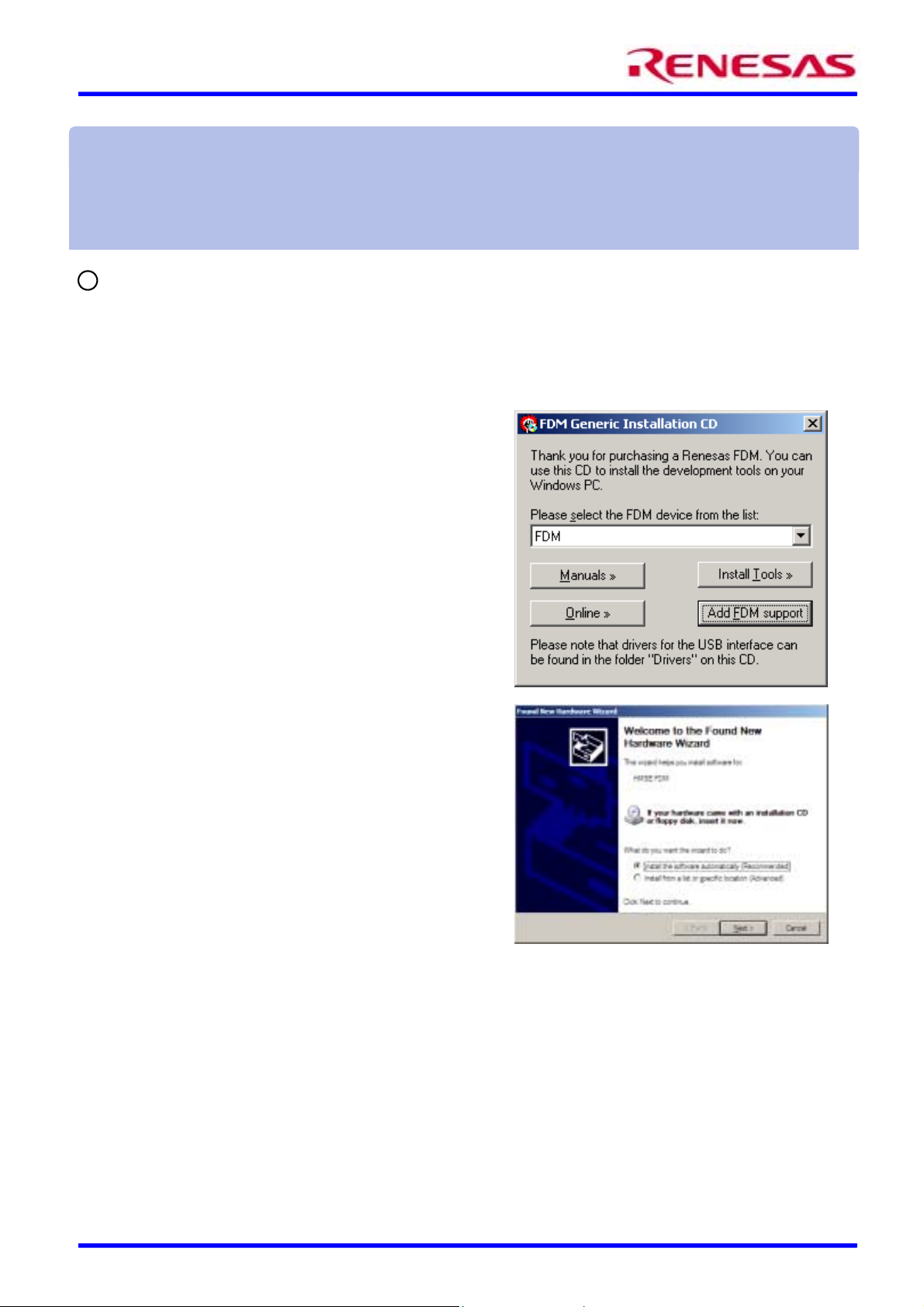
Once the menu program is running:
• Select "FDM" from the drop down list.
• The buttons suffixed with the '»' symbol will display a popup
menu when clicked. The content above the separator in these
menus changes dynamically, depending on the selected EDK
device.
• If you do not have FDT already installed, you should click the
"Install Tools »" button and complete the installation of FDT.
• Click "Add EDK Support" to install the sample EDK
kernel(s) with support for the FDM pin settings.
• Use of the FDM requires FDT kernels which have settings for
controlling the mode pins of the target device. The only
kernels which have these settings are for EDK’s. It is possible
however, to manually add these settings to other kernels; this
is covered by a separate application note.
Once FDT is installed, it is possible to plug in the FDM to the PC
USB port using the supplied USB A-B cable – the first time this is
done it will install the driver: ensure that the FDM is not plugged
into a target device before this first connection is made. Under
Windows 98, Me, and 2000 the driver should install automaticall y
without prompting for a driver disk. Under Windows XP the
“Found New Hardware Wizard” will launch. Select “Install the
software automatically” and click “Next” to complete the
installation.
Once the driver has been successfully installed the red LED will
illuminate continuously and the Green LED will begin to flash. The
installed driver will be loaded each time the FDM is plugged in.
Note that the green LED will not flash if the driver is not
installed correctly (e.g. FDT is not installed).
Documentation
The CD's menu program will automatically detect if you need to install the Acrobat Reader when you first select a PDF
document from the Manuals popup menu. Alternatively, you may install Acrobat Reader manually from the CD's menu
program by selecting "Manuals »", "Acrobat Reader".
Renesas Technology Europe Ltd Page 1 of 4 D002936_11_v01
Page 2
FDM Quickstart Guide
2
Generating a Test Project
Once you have installed the required software you can quit the menu
program and start the Flash Development Toolkit (FDT). This
example uses the EDK 2282 but the method is valid for other EDK’s.
• Start FDT by using the Start Menu to navigate to “Start”,
“Programs”, “Renesas”, “Flash Development Toolkit
2.2” and select “Flash Development Toolkit 2.2”.
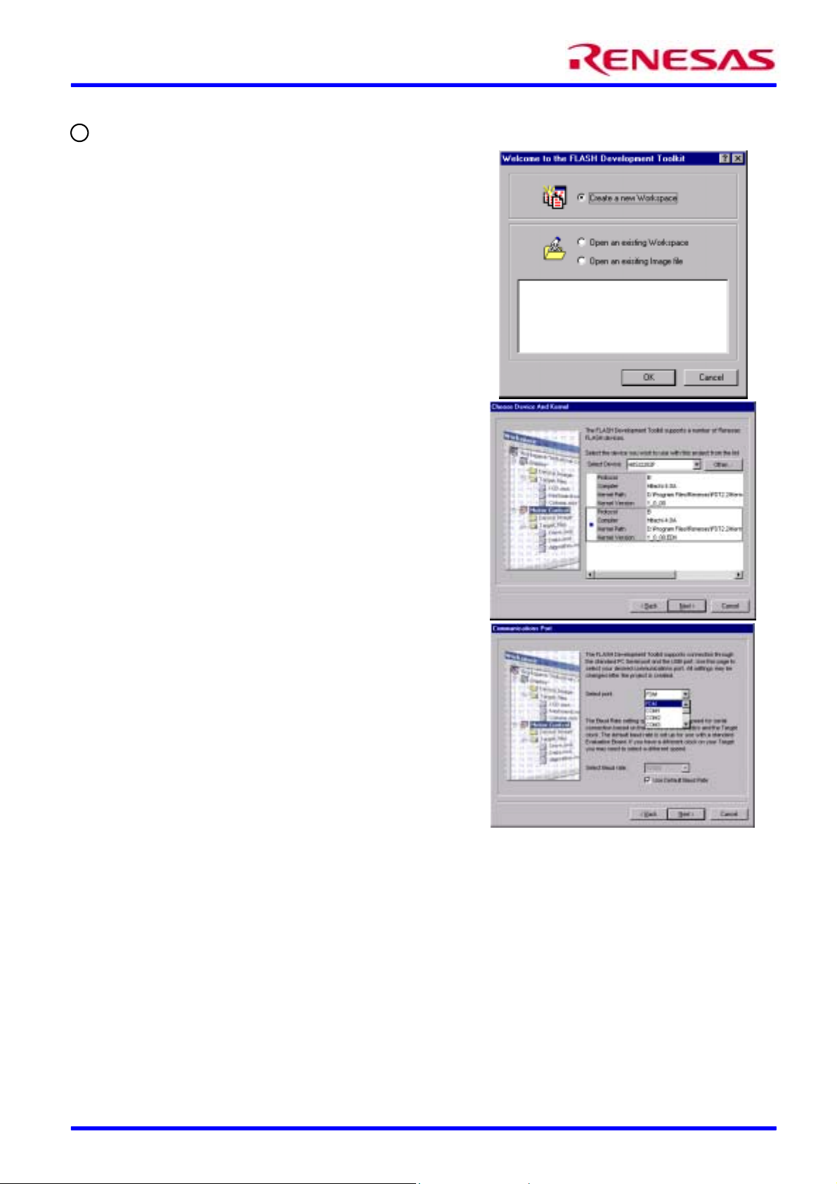
• In the “Welcome” dialog box, select “Create a new
Workspace” and click “OK”.
• In the “New Project Workspace” dialog box, change the
directory if the default is not where you would like to save
it.
• Enter the Workspace Name, “EDK with FDM”. Click
“OK”.
• A dialog box will be displayed asking if you want to run the
project wizard to add a new project; click “Yes”.
• Enter the Project Name, “EDK2282” (replace with an
appropriate name if using another EDK). Click “Next”.
• In the “Choose Device And Kernel” dialog, select the
EDK target device from the drop down list: "H8S/2282F"
in this example. Then select the Kernel with .EDK at the
end of the kernel version (See screenshot). Click “Next”.
[Note that the EDK kernels are not installed as part of FDT
and should have been installed separately in order to use the
FDM with FDT 2.2]
• In the “Communications Port” dialog, click the Select Port
combo box to display the list, scroll up to the top and select
“FDM”. If the Baud rate required is not the default
selection, the “Use Default Baud Rate” option must be
unchecked before the required setting can be set. Click
“Next”.
• For EDK’s the default options for “Crystal Frequency”,
“Clock Mode”, “CKM” and “CKP” should remain
unchanged in the “Device Settings” dialog, so click “Next”
to continue.
• In the “Connection Type” dialog, select “BOOT Mode”
connection and click “Next”.
• In the “Programming Options” dialog, select Messaging
level “Advanced” and click “Finish”.
The project is now setup and the mode pin settings have been
read from the flash configuration file for the selected kernel. The
next stage is to connect the hardware.
Renesas Technology Europe Ltd Page 2 of 4 D002936_11_v01
Page 3

FDM Quickstart Guide
3
Physical connections and precautions of use
1) Ensure that the EDK power is off and that the USB cable is not connected to the FDM.
2) Set the EDK jumper settings to use the FDM. The RXDISn jumper should be set ON to disable the standard serial
port. Check with the EDK user manual for other settings required (normally FWE devices need the UPM jumper on
and FWP devices need the UPM jumper off). The EDK2282 requires RXDISn = ON and UPM = ON.
3) Plug the 14 way ribbon cable into the FDM at one end and into the “FLASH PROGRAMMING” header on the
EDK. Ensure that the correct header on the EDK is used (some EDK’s have additional 14 way headers for other
uses) and that the connector is orientated correctly.
4) Switch on the power to the EDK. Ensure that the EDK is not in Boot mode. DO NOT ACTIVATE BOOT MODE
as this could lead to contention of the mode pins; the FDM will control these.
5) Plug the USB cable into the FDM.
The green LED will blink as follows:
a. Long blink (to show successful USB enumeration)
b. Long Pause
c. Short blink (to show UConnect made – EDK is connected)
d. Short Pause
e. Short blink (to show I/O lines voltage matching active)
f. Short Pause
g. Short blink (to show Serial lines voltage matching active)
h. Long Pause
i. Long Pause
FDM 14 way target connector pin out
TARGET BOARD
SCK 1
FW 3
TXD 5
MD4 7
PVCC 9
RXD 11
RESn 1 3
2 GND
4 MD0
6 MD1
8 UVCC
10 MD2
12 MD3
14 GND
Pin 8 : I/O voltage (UV CC)
Pin 9 : Serial voltage (PVCC)
If PVCC not required by target board
microcontroller, leave not connected.
14-w ay IDC
female - female
1:1 ribbon cable
To F DM
4
Example of connection using FDT with the FDM
The following procedure explains how to connect and program the EDK using the FDM from FDT using the project setup in
section
Renesas Technology Europe Ltd Page 3 of 4 D002936_11_v01
2
:
Page 4

FDM Quickstart Guide
1. Select the menu item “Device”, “Connect to Device”. FDT will now setup communications with the FDM, reset the
target board into boot mode and boot the device. An example of the messages displayed (Advanced messaging) is shown
below:
Connecting to device 'H8S/2282F' on 'FDM'
Configuration:
'BOOT Mode' connection - using emulated interface
Opening port 'FDM' ...
FDM Reset Active
FDM Mode Pin Setting Active
FDM setting reset pin state: 0x40, 0x00
FDM setting reset pin direction: 0x40, 0x40
FDM setting pin state: 0xBF, 0x81
FDM setting pin direction: 0xBF, 0x85
FDM sending reset: 0x00, 0x00, 0x01, 0xF4
Querying FDM version info...
FDM v01.02, firmware 1.05, product 1.02, build 884
FDM SN: 00000 HMSE FDM
Initiating BOOT SCI sequence
Attempting 9600
Using micro-Kernel : 'C:\Program Files\Renesas\FDT2.2\Kernels\ProtB\2282\hitachi\1_0_00.edk\uGen2282.cde'
Downloading and verifying micro kernel...
micro-Kernel download successful
Changing baud rate to 57600 bps
Set baud rate value = 57600
Downloading main kernel C:\Program Files\Renesas\FDT2.2\Kernels\ProtB\2282\hitachi\1_0_00.edk\Genm2282.cde'
Main kernel download complete...
Connection complete
2. Add the file(s) to be programmed to the project using “Project”, “Add Files to Project…”
3. Build the device image using “Project”, “Build Device Image”
4. Right click on the built image and select “Download Image to Device”. An example of the messages is shown below:
Processing S-Record file :C:\TEMP\FDT76.tmp'
Data loaded at the following positions:
H'00000000 - H'00000003 Length : H'00000004
H'00001000 - H'0000111D Length : H'0000011E
H'0001F600 - H'0001FE4B Length : H'0000084C
Downloaded the operation module
Writing image to device...
Data programmed at the following positions:
H'00000000 - H'0000007F Length : H'00000080
H'00001000 - H'0000117F Length : H'00000180
H'0001F600 - H'0001FE7F Length : H'00000880
2.63 K programmed in 1 seconds
Image successfully written to device
Download operation complete
Congratulations! You have successfully installed the software and programmed an EDK using the FDM. You can now
select “Device”, “Disconnect from Device”. When asked if you want to reset the device, selecting “Yes” will reset the target
board into User Mode where the programmed code will begin to execute. To continue learning about the tools and the board
please read all other supporting documentation.
Technical Support
FDT is supplied as freeware without technical support. Technical support is limited to that which is provided on the Renesas
Technology Europe’s website at: http://www.eu.renesas.com/tools
Appendix:
Explanation of Flash Configuration File settings for FDM usage:
In each FDT 2.2 kernel directory there is a .fcf file for each supported device, which holds information about the device and
kernel. The [Pin State] section holds details for setting the mode pins from the FDM. The fields are:
BootModeDirection, BootModeState, UserModeDirection, UserModeState and UserProgramModeState and represent a
bit field as follows:
0x80 0x40 0x20 0x10 0x08 0x04 0x02 0x01
FWx
(FWE / FWP)
RESERVED
n
must be 0
Dir
SCK MD4 MD3 MD2 MD1 MD0
Where Direction 0=Input, Direction 1=Output. State (if Dirn is output) 0=Drive Output Low, State 1=Dri ve Output High
Eg. xxxxModeDirection = 0x87 sets the FWx, MD2, MD1 and MD0 pins as outputs,
xxxxModeState = 0x81 drives the FWx and MD0 pins high, and the MD2 and MD1 pins l ow f or xxx xMode
WARNING – INCORRECT VALUES IN THE FCF FILE COULD RESULT IN DAMAGE TO THE HARDWARE
Note that editing a configuration file will render its checksum invalid. FDT will display a warning for fcf files with invalid
checksums but will not prevent their use. Supplied kernels should not be edited; if different settings are required, it is
suggested that the kernel directory should be copied to an alternative location and the kernel version should be changed
in the fcf file (the directory name should match the kernel version). This prevents accidental corruption of the supplied
kernels.
Renesas Technology Europe Ltd Page 4 of 4 D002936_11_v01
 Loading...