

Page 1
Application Note
Document Name
Document No.
Bluetooth Low Energy Protocol Stack
User's Manual
R01UW0095E
API Reference Manual: Basic
R01UW0088E
Application Note: Sample Program
R01AN1375E
Application Note: rBLE Command Specification
R01AN1376E
BLE Virtual UART Application
R01AN3130E
Security Library
R01AN3777E
RL78/G1D
User's Manual: Hardware
R01UH0515E
RL78/G1D Module
User's Manual: Hardware
R02UH0004E
User's Manual: Firmware
R01UW0160E
Application Note: Module Control Software
R01AN3362E
RL78/G14
User's Manual: Hardware
R01UH0186E
Bluetooth® Low Energy Protocol Stack
Fast Prototyping Board Host Sample
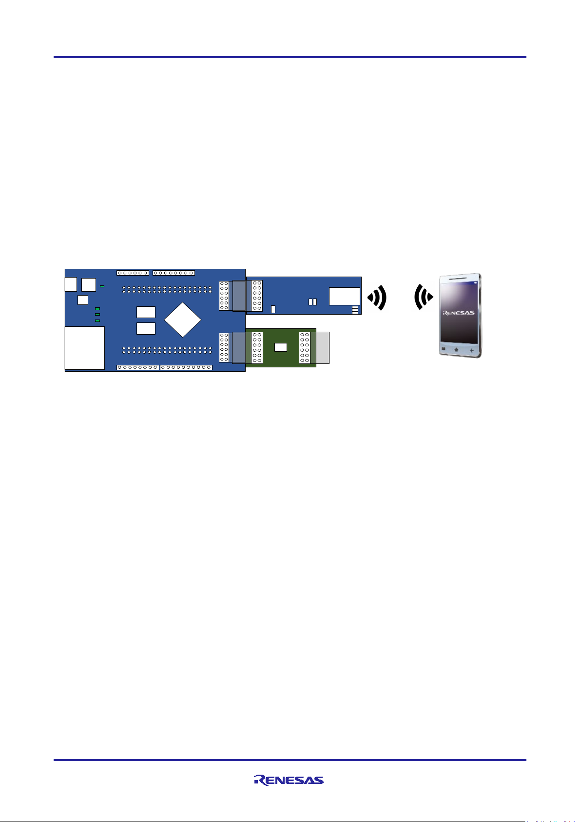
Introduction
This application note describes how to transmit sensor (Renesas HS3001 Humidity and Temperature
Sensor) information via Bluetooth using the RL78/G14 Fast Prototyping Board and the RL78/G1D BLE
Module Expansion Board.
The Host Sample is a Host MCU program executed by the RL78/G14 Fast Prototyping Board using the
Bluetooth low energy protocol stack modem configuration. Controls the RL78/G1D Module on the RL78/G1D
BLE Module Expansion Board connected by the UART 2-wire branch connection. It can also save pairing
and pairing information with the Security Library.
This document also describes the hardware configuration that runs the Host Sample, the software
configuration, the procedure for checking the smartphone and communication, and the Bluetooth
communication sequence.
Target Device
RL78/G14 Fast Prototyping Board (Parts Number: RTK5RLG140C00000BJ)
RL78/G1D BLE Module Expansion Board (Parts Number: RTKYRLG1D0B00000BJ)
Related Documents
R01AN4834EJ0120 Rev.1.20 Page 1 of 41
Mar.2.21
Page 2

Bluetooth® Low Energy Protocol Stack Fast Prototyping Board Host Sample
Contents
1. Overview ................................................................................................................................. 4
2. Development Environment ....................................................................................................... 5
2.1 Hardware Environment ............................................................................................................................ 5
2.2 Software Environment ............................................................................................................................. 5
3. Host Sample Compositions ...................................................................................................... 6
3.1 Device Compositions ............................................................................................................................... 6
3.1.1 PmodTM Interface ................................................................................................................................... 7
3.1.2 User Switch (SW_USR) ........................................................................................................................ 7
3.2 Software Compositions ........................................................................................................................... 8
3.3 Peripheral Function Compositions ........................................................................................................ 10
3.4 File Compositions .................................................................................................................................. 13
4. How to Build .......................................................................................................................... 16
4.1 CS+ for CC ............................................................................................................................................ 16
4.2 e2 studio ................................................................................................................................................. 16
4.3 Writing HEX file using Renesas Flash Programmer ............................................................................. 17
5. Host Sample Demo................................................................................................................ 18
5.1 Install GATTBrowser ............................................................................................................................. 18
5.2 Execute Host Sample ............................................................................................................................ 18
5.2.1 CS+ for CC .......................................................................................................................................... 19
5.2.2 e2 studio ............................................................................................................................................... 19
5.3 Communication operation check using a smartphone .......................................................................... 20
5.3.1 Android Device .................................................................................................................................... 20
5.3.2 iOS Device ........................................................................................................................................... 22
6. Host Sample Software Operation ........................................................................................... 24
6.1 rBLE Command and rBLE Event ........................................................................................................... 24
6.2 Main Loop .............................................................................................................................................. 25
6.3 GPCP Transmission/Reception Function .............................................................................................. 26
6.3.1 Transmit Function ................................................................................................................................ 26
6.3.2 Receive Function ................................................................................................................................. 27
6.4 UART 2-wire Branch Connection .......................................................................................................... 28
6.4.1 Transmission Process ......................................................................................................................... 28
6.4.2 Reception Process .............................................................................................................................. 29
6.4.3 Application Circuits .............................................................................................................................. 30
6.5 Disable Sensor ...................................................................................................................................... 31
7. Sequence Chart ..................................................................................................................... 32
7.1 Main sequence chart ............................................................................................................................. 32
R01AN4834EJ0120 Rev.1.20 Page 2 of 41
Mar.2.21
Page 3

Bluetooth® Low Energy Protocol Stack Fast Prototyping Board Host Sample
7.2 Step1. rBLE Initialize sequence ............................................................................................................ 33
7.3 Step2. GAP Initialize sequence ............................................................................................................. 33
7.4 Step3. Broadcast sequence .................................................................................................................. 34
7.5 Step4. Connection sequence ................................................................................................................ 34
7.6 Step5. Profile Enable sequence ............................................................................................................ 35
7.7 Step6. Remote Device Check sequence .............................................................................................. 35
7.8 Step7. Pairing sequence ....................................................................................................................... 36
7.9 Step8. Start Encryption sequence ......................................................................................................... 36
7.10 Step9. Profile Communication sequence .............................................................................................. 37
7.11 Step10. Disconnection sequence .......................................................................................................... 37
8. Appendix ............................................................................................................................... 38
8.1 ROM size, RAM size ............................................................................................................................. 38
8.2 References ............................................................................................................................................ 38
8.3 Terminology ........................................................................................................................................... 39
Revision History ............................................................................................................................ 41
The Bluetooth
®
word mark and logos are registered trademarks owned by Bluetooth SIG, Inc. and any use of
such marks by Renesas Electronics Corporation is under license. Other trademarks and registered
trademarks are the property of their respective owners.
TM
Pmod
is registered to Digilent Inc.
R01AN4834EJ0120 Rev.1.20 Page 3 of 41
Mar.2.21
Page 4

Bluetooth® Low Energy Protocol Stack Fast Prototyping Board Host Sample
1. Overview
This application note describes how to transmit sensor information via Bluetooth using the RL78/G14 Fast
Prototyping Board and the RL78/G1D BLE Module Expansion Board. The sensor uses the Renesas HS3001
Humidity and Temperature Sensor Module (humidity, temperature).
The Host Sample is a Host MCU program that runs on the RL78/G14 Fast Prototyping Board using the
Bluetooth Low Energy Protocol Stack (BLE Protocol Stack) Modem configuration. Controls the RL78/G1D
module (RY7011) that configures the RL78/G1D BLE Module Expansion Board of the BLE MCU connected
by UART 2-wire branch connection
and pairing information can be saved in the RL78/G14 Fast Prototyping Board.
)
(Note1
. In addition, by using the Security Library
(Note2)
, pairing execution
The module firmware for operation check is written in RY7011 at the factory, and can be controlled from the
(Note3)
Host MCU program using the rBLE API
of the BLE protocol stack.
Notes: 1. In addition to TxD and RxD, which are UART data signal lines, the Host MCU has a WAKEUP
signal line for waking up the BLE MCU at the time of data transmission. The WAKEUP signal line
branches TxD of Host MCU and connects with WAKEUP of BLE MCU. For connection between
Host MCU and BLE MCU, refer to "6.4.3 Application Circuits".
®
2. For details on the Security Library, refer to the "Bluetooth
Low Energy Protocol Stack Security
Library" (R01AN3777).
3. For details on the BLE protocol stack API, refer to the "Bluetooth® Low Energy Protocol Stack API
Reference Manual : Basics" (R01UW0088).
R01AN4834EJ0120 Rev.1.20 Page 4 of 41
Mar.2.21
Page 5

Bluetooth® Low Energy Protocol Stack Fast Prototyping Board Host Sample
2. Development Environment
Describes the build environment and the development environment used to operation check.
2.1 Hardware Environment
Host
• PC/AT
• Processor: 1GHz or faster (with support for hyper threading and multicore CPUs)
• Main Memory: We recommend 2GB or more.
• Display: Graphics resolution should be at least 1024 x 768, and the mode should display at least
• Interface: USB2.0
Development Board
• RL78/G14 Fast Prototyping Board (RTK5RLG140C00000BJ)
• RL78/G1D BLE Module Expansion Board (RTKYRLG1D0B00000BJ)
• Renesas HS3001 Humidity and Temperature Sensor Module with I2C Interface
Smartphone
• Android device or iOS device
TM
compatible computer
65,536 colors.
2.2 Software Environment
OS
• Windows7 or later
Integrated Development Environment/Compiler
Use one of the following integration environment and compiler combinations.
• CS+ for CC V8.05.00 / CC-RL V1.10.00
2
• e
studio 2021-01 (64-bit version) / CC-RL V1.10.00
2
• e
studio V7.8.0 (32-bit version) / CC-RL V1.10.00
R01AN4834EJ0120 Rev.1.20 Page 5 of 41
Mar.2.21
Page 6
Bluetooth® Low Energy Protocol Stack Fast Prototyping Board Host Sample
RL78/G14
Fast Prototyping Board
RL78/G1D BLE Module
Expansion
Renesas HS3001
Humidity and Temperature
Sensor Module
Smartphone
PMOD1
PMOD
Local Device (Peripheral)
Remote Device (Central)
Mic ro
USB
RX231
ELED
LED_P
Coin cell
battery holder
Pmod
Connec ter 2
Pmod
Connec ter 1
LED0
RESET
SW
User’ s
SW
LDO
10 Pin socket
8 Pin soc ket
8 Pin soc ket
6 Pin soc ket
RL78/G14
80-LFQFP
LED1
Pmod
conn ecter
RL78/G1D
BLE Module
X
1
C2
C3
C1
R1
R2
Pmod
conn ecter
HS3001
Pmod
conn ecter
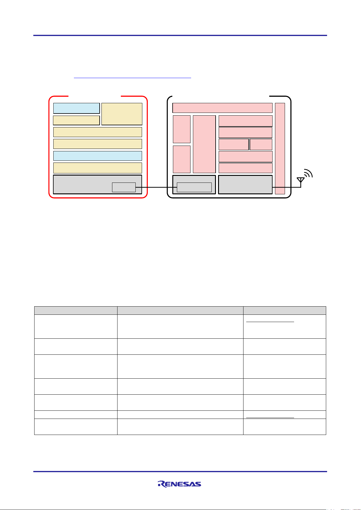
3. Host Sample Compositions
3.1 Device Compositions
"Figure 3-1 Device Compositions" shows the device configuration diagram used in this application note.
The Local Device (Peripheral) consists of the RL78/G14 Fast Prototyping Board, which is the Host MCU, and
the RL78/G1D BLE Module Expansion Board, which is the BLE MCU. The two boards are connected by
PMOD1 and communicate via UART 2-wire branch connection. Also, to transmit sensor data from the
RL78/G1D BLE Module, connect Renesas HS3001 Humidity and Temperature Sensor Module (humidity,
temperature) to PMOD2
Remote Device (Central) uses the smartphone of Android device or iOS device.
Note
of the RL78/G14 Fast Prototyping Board. PMOD2 communicates over IICA.
Board
2
Note
Figure 3-1 Device Compositions
Note: Connect to PMOD2 when using the I2C communication Pmod
TM
module. Then change the pin that
assigns the function of serial interface IICA with the peripheral I/O redirect function of RL78/G14.
Refer to "Table 3-2 PMOD2 connector pin assignment" for pin assignment.
The overview of the host sample is shown below.
It uses rBLE API and executes below operations.
• After power up, it starts broadcasting.
• Connection is established by the connection request from Remote Device.
• It executes pairing and starting encryption if Remote Device requires.
• Enable the General Purpose Communication Profile with Indication permission from Remote
Device.
• Erase the security information stored in the data flash with the USER SW.
It is implemented a simple scheduler for management processing sequence.
It changes the RL78/G14 state into the STOP mode if there is nothing to execute.
It supposes that peer device is a smart phone (Android device or iOS device).
(Tablet)
R01AN4834EJ0120 Rev.1.20 Page 6 of 41
Mar.2.21
Page 7
Bluetooth® Low Energy Protocol Stack Fast Prototyping Board Host Sample
RL78/G14 Fast Prototyping Board
PmodTM
RL78/G1D BLE Module Expansion Board
Function Name
Pin No.
Pin No.
Pin No.
Function Name
P74/KR4/INTP8
33 1 2
P30/INTP3/RTC1HZ
P51/INTP2/SO00/TxD0/TOOLTxD/TRGIOB
42 2 8
P11/SI00/RxD0/TOOLRxD/SDA00/(TI06)/(TO06)
P50/INTP1/SI00/RxD0/TOOLRxD/SDA00/TRGIOA/(TRJO0)
41 3 7
P12/SO00/TxD0/TOOLTxD/(TI05)/(TO05)
P30/INTP3/RTC1HZ/SCK00/SCL00/TRJO0
40 4 9
P10/SCK00/SCL00/(TI07)/(TO07)
GND
- 5 -
GND
VCC
- 6 -
VDD
P140/PCLBUZ0/INTP6
2 7 -
N.C
P130
72 8 24
RESET#
P147/ANI18/VCOUT1
58 9 -
N.C
P146
57
10
23
P40/TOOL0
GND
-
11
-
GND
VCC
-
12
-
VDD
RL78/G14 Fast Prototyping Board
PmodTM
Renesas HS3001 Humidity and Temperature Sensor Module
Function Name
Pin No.
Pin No.
Function Name
P16/TI01/TO01/INTP5/TRDIOC0/IVREF0/(SI00)/(RxD0)
48
1
NC
P13/TxD2/SO20/TRDIOA1/IVCMP1
51
2
NC
(
)P14/RxD2/SI20/SDA20/TRDIOD0/(SCLA0)
50
3
SCL
(
)P15/SCK20/SCL20/TRDIOB0/(SDAA0)
49
4
SDA
GND
- 5 VSS
VCC
- 6 VDD
P141/PCLBUZ1/INTP7
1 7 NC
P110/(INTP11)
55
8
NC
P17/TI02/TO02/TRDIOA0/TRDCLK/IVCMP0/(SO00)/(TxD0)
47
9
NC
P111
56
10
NC
GND
-
11
VSS
VCC
-
12
VDD
3.1.1 PmodTM Interface
The PmodTM interface connector pin assignments in "Figure 3-1 Device Compositions" are shown. The
function used by each pin is shown in blue.
(1) PMOD1
Table 3-1 PMOD1 connector pin assignment
(2) PMOD2
Table 3-2 PMOD2 connector pin assignment
Note
Note
Note: Change the function assignment of RL78/G14 with the peripheral I/O redirect function. Connect to
TM
PMOD2 when using the I2C communication Pmod
module.
3.1.2 User Switch (SW_USR)
Erases the security information of the RL78 / G14 data flash.
For security information, refer to "Bluetooth
R01AN4834EJ0120 Rev.1.20 Page 7 of 41
Mar.2.21
®
Low Energy Protocol Stack Security Library" (R01AN3777).
Page 8
Bluetooth® Low Energy Protocol Stack Fast Prototyping Board Host Sample
Software
Functions
When developing software
Host Application
Initializing rBLE
Registering rBLE event callbacks
Need to be coded
Security Library
Pairing, Bonding,
Encryption, Privacy
No need to be coded
(provided by package)
General Purpose
(GPCP)
Custom Profile using GATT APIs
No need to be coded
rBLE_Host
Providing rBLE APIs
Executing rBLE event callbacks
No need to be coded
(provided by package)
RSCIP
Controlling serial communication
No need to be coded
(provided by package)
Peripheral Driver
Controlling Host MCU peripheral hardware
Need to be coded
Low Level Peripheral Driver
Controlling Host MCU peripheral hardware
primitively
No need to be coded
(generated by tool)
Host Ap plicatio n
rBLE_Ho s t
RSCIP
Periph e ral Drive r
Low Level Peripheral Driver
RL78/G14(Host MCU)
Mo dem Applic a t io n
rBLE_C o re
Pro file
Host Stack
Co ntro ller St ac k
Se rial
Driver
Peripheral
RWKE(OS)
RY7011(BLE MCU-Modem)
Peripheral
RF Driver
RF/BB
RS C IP
Se rialSe rial
Periphe ral Driver
General
Purpose
C ommunication
Profile
GPCP
GATT
Database
Security Library
3.2 Software Compositions
The software composition of RL78/G14 which is a Host MCU and RY7011 which is a BLE MCU is shown.
Firmware for operation check is written in RY7011 at the time of shipment, and it supports some profiles. In
this document, General Purpose Communication Profile (GPCP) is used. For other profiles, refer to "7.
Profile" in the "RL78/G1D Module Firmware User's Manual" (R01UW0160).
Figure 3-2 Software Compositions
The software of Host MCU consists of low level peripheral drivers and peripheral drivers which controls MCU
peripheral hardware, RSCIP (Renesas Serial Communication Interface Protocol), rBLE_Host which provides
rBLE APIs, host application which controls the system, General Purpose Communication Profile (GPCP)
using the GATT API, Security Library that provides security functions such as pairing.
Low Level Peripheral driver code is generated by the Code Generator. RSCIP and rBLE_Host are included
in BLE protocol stack package and provided code. When developing software, it is necessary to use the
latest code which is provided by BLE protocol stack package.
Communication Profile
Notes: 1. Code files for software development are provided by BLE protocol stack package.
2. Code files for software development are generated by the Code Generator.
R01AN4834EJ0120 Rev.1.20 Page 8 of 41
Mar.2.21
Table 3-3 Host MCU Software Composition
Scheduling rBLE command execution
(provided by package)
Note2
Note1
Note1
Note1
Note1
Page 9
Bluetooth® Low Energy Protocol Stack Fast Prototyping Board Host Sample
Software
Functions
Modem Application
Controlling RSCIP and rBLE
RWKE
Managing the whole system schedule and memory resource.
RSCIP
Controlling serial communication
Peripheral Driver/Serial Driver
Controlling BLE MCU peripheral hardware
rBLE_Core
Providing rBLE APIs
Profile
Providing Profiles functions
Host Stack
Providing GAP, GATT, SM, L2CAP functions
GSCP GATT Database
GATT Database of General Purpose Communication Profile
Controller Stack
Providing LL functions
The software of BLE MCU consists of RF driver which controls RF/BB, Host/Controller stacks, Profiles,
rBLE_Core, Serial Driver and RSCIP for communicating with Host MCU, RWKE (Renesas Wireless Kernel
Extension) which manages the system and Modem application. The build environment is provided by
"RL78/G1D Module Module Control Software" (R01AN3362).
Table 3-4 BLE MCU Software Composition
R01AN4834EJ0120 Rev.1.20 Page 9 of 41
Mar.2.21
Page 10
Bluetooth® Low Energy Protocol Stack Fast Prototyping Board Host Sample
Peripheral Function
Purpose
Necessity
Note
Pin assignment
Used for IICA communication between the RL78/G14 Fast
Optional
Clock generator
Used to set the operating frequency of RL78/G14.
Mandatory
Port
P74: Used as WAKEUP pin of UART 2-wire branch
Mandatory
P43: Used for LED0 of RL78/G14 Fast Prototyping Board.
Optional
Serial-UART0
Used for UART communication between RL78/G14 Fast
Mandatory
Serial-IICA0
Used for IICA communication between RL78/G14 Fast
Optional
Timer-TAU0
Used for A/D conversion wait time of Renesas HS3001
Optional
12-bit Interval timer
Used for the rBLE timer function.
Mandatory
Interrupt Functions -
Used for interrupting the user switch (SW_USR).
Optional
3.3 Peripheral Function Compositions
The following shows the RL78/G14 peripheral functions used on the RL78/G14 Fast Prototyping Board.
Table 3-5 Peripheral Functions
(Peripheral I/O redirect
function)
Prototyping Board and the Renesas HS3001 Humidity and
Temperature Sensor Module.
At reset of RL78/G14, IICA0 pin is assigned to SCLA0=P60
and SDAA0=P61. Communication can be performed with
IICA0 by assigning SCLA0=P14 and SDAA0=P15 to the
PMOD2 I/F of the RL78/G14 Fast Prototyping Board with
the peripheral I/O redirect function.
connection with RL78/G1D BLE Module Expansion Board.
P130: Used as reset release pin of RL78 / G1D BLE Module
Expansion Board.
P44: Used for LED1 of RL78/G14 Fast Prototyping Board.
Prototyping Board and RL78/G1D BLE Module Expansion
Board.
Prototyping Board and Renesas HS3001 Humidity and
Temperature Sensor Module.
Humidity and Temperature Sensor Module.
INTP0
Note: Peripheral hardware which Host MCU required to use the rBLE is classified "Mandatory", other
peripheral hardware is classified "Optional".
R01AN4834EJ0120 Rev.1.20 Page 10 of 41
Mar.2.21
Page 11
Bluetooth® Low Energy Protocol Stack Fast Prototyping Board Host Sample
Peripheral Function
Purpose
Setting
Port assignment
PIOR2
Set to 1
Clock generator
mode
High-speed main mode
EVDD
1.8(V)≦EV
5.5(V)
High-speed on-chip
64(MHz)
Low-speed on-chip
15kHz
RTC, interval timer clock
15(fIL)kHz
CPU/peripheral hardware
32000(fIH)kHz
Port
P43
Output
P44
Output
P74
Output
P130
Output
Serial
Data bit length
8 bit
Data direction
LSB
Parity
no parity
Stop bit length
1 bit
Data phase
standard
Baudrate
115200(bps)
Interrupt (INTSR0)
High
Callback function
Reception transfer end
Serial
Transfer mode
Single mode
Data bit length
8 bit
Data direction
LSB
Parity
no parity
Stop bit length
1 bit
Data phase
standard
Baudrate
115200(bps)
Interrupt (INTST0)
Low
Table 3-6 Peripheral Functions Setting
(Peripheral I/O redirect
function)
oscillator
oscillator
clock
(Assign SCLA0 to P14)
(Assign SDAA0 to P15)
2.7(V)≦VDD≦5.5(V)
≦
DD
(RL78/G14 Fast Prototyping Board LED0)
(RL78/G14 Fast Prototyping Board LED1)
(RL78/G1D BLE Module Expansion Board
WAKEUP pin)
SAU0 - UART0 - Receiving
SAU0 - UART0 - Transmitting
(RL78/G1D BLE Module Expansion Board
RESET pin)
Error
R01AN4834EJ0120 Rev.1.20 Page 11 of 41
Mar.2.21
Page 12
Bluetooth® Low Energy Protocol Stack Fast Prototyping Board Host Sample
Callback function
Transmission end
Serial
Count clock
f
/2
Own address
16
Mode
standard
Transmission clock
100000(bps)
Transmission completion
Low
Callback function
Master transmission completion
Callback extension function
Master transmission/reception callback
Timer
Interval period
1ms
Interrupt setting
count completion interrupt
Priority
Low
12-bit interval timer
Interval timer
used
Interval period
10ms
Interrupt
interval period expiration interruption
Priority
Low
Interrupt
Valid edge
Falling edge
Priority
Low
CLK
IICA0 - Single master
interrupt priority (INTIICA0)
Master reception completion
Master error
with stop condition generation
TAU0 - channel 0- Interval
timer
(INTTM00)
INTP0 - External interrupt
(INTIT)
R01AN4834EJ0120 Rev.1.20 Page 12 of 41
Mar.2.21
Page 13

Bluetooth® Low Energy Protocol Stack Fast Prototyping Board Host Sample
RL78G14_Fast_Prototyping_Board_HostSample
HostSample
Platform
driver
hs3001
r_hs3001.c
Renesas HS3001 driver code file
r_hs3001.h
Renesas HS3001 driver header file
serial
uart.c
UART driver code file
uart.h
UART driver header file
dataflash
dataflash.c
Dataflash driver code file
dataflash.h
Dataflash driver header file
eel_descriptor_t02.c
EEPROM Emulation Library driver code file
eel_descriptor_t02.h
EEPROM Emulation Library driver header file
fdl_descriptor_t02.c
Data Flash Access Library driver code file
fdl_descriptor_t02.h
Data Flash Access Library driver header file
cc_rl
eel.h
EEPROM Emulation Library API header file
eel.lib
EEPROM Emulation Library
eel_types.h
EEPROM Emulation Library Type header file
fdl.h
Data Flash Access Library API header file
fdl.lib
Data Flash Access Library
fdl_types.h
Data Flash Access Library Type header file
timer
timer.c
timer driver code file
timer.h
timer driver header file
include
arch.h
(R)
architecture header file
compiler.h
(R)
compiler header file
ll.h
(R)
low level macro header file
rscip_api.h
(R)
RSCIP callback header file
types.h
(R)
type definition header file
rBLE
├─host
│ │ rble_host.c
(R)
rBLE_Host code file
│ │ rble_if_api_cb.c
(R)
rBLE API callback code file
│ │
│ ├─gap
│ │ rble_api_gap.c
(R)
GAP API code file
│ │
│ ├─gatt
│ │ rble_api_gatt.c
(R)
GATT API code file
│ │
│ ├─sm
│ │ rble_api_sm.c
(R)
SM API code file
│ │
│ └─vs
│ rble_api_vs.c
(R)
VS API code file
3.4 File Compositions
The file composition of the host sample is shown below.
The (R) mark of file configuration indicates that the file is included in the BLE protocol stack package. When
developing software, it is necessary to use the latest code which is provided by BLE protocol stack package.
├─
│ ├─
│ │ ├─
│ │ │ ├─
│ │ │ │
│ │ │ │
│ │ │ │
│ │ │ ├─
│ │ │ │
│ │ │ │
│ │ │ │
│ │ │ ├─
│ │ │ │ │
│ │ │ │ │
│ │ │ │ │
│ │ │ │ │
│ │ │ │ │
│ │ │ │ │
│ │ │ │ │
│ │ │ │ └─
│ │ │ │
│ │ │ │
│ │ │ │
│ │ │ │
│ │ │ │
│ │ │ │
│ │ │ │
│ │ │ └─
│ │ │
│ │ │
│ │ │
│ │ └─
│ │
│ │
│ │
│ │
│ │
│ │
│ └─
│
│
│
│
│
│
│
│
│
│
│
│
│
│
│
R01AN4834EJ0120 Rev.1.20 Page 13 of 41
Mar.2.21
Page 14

Bluetooth® Low Energy Protocol Stack Fast Prototyping Board Host Sample
│
├─include
│ │ db_handle.h
(R)
data base handle header file
│ │ prf_sel.h
(R)
profile select header file
│ │ rble.h
(R)
rBLE macro header file
│ │ rble_api.h
(R)
rBLE API header file
│ │ rble_app.h
(R)
rBLE SCP API header file
│ │ rble_trans.h
(R)
rBLE communication header file
│ │
│ └─host
│ rble_host.h
(R)
rBLE_Host header file
│
├─rscip
│ rscip.c
(R)
RSCIP code file
│ rscip.h
(R)
RSCIP header file
│ rscip_cntl.c
(R)
RSCIP control code file
│ rscip_cntl.h
(R)
RSCIP control header file
│ rscip_ext.h
(R)
RSCIP external callback header file
│ rscip_uart.c
(R)
RSCIP serial communication code file
│ rscip_uart.h
(R)
RSCIP serial communication header file
│
├─sample_app
│ │ app.c
host application code file
│ │ r_hs3001_app.c
Renesas HS3001 application code file
│ │ r_hs3001_app.h
Renesas HS3001 application code file
│ │
│ └─seclib
│ seclib.c
Security Library code file
│ seclib.h
Security Library header file
│ secdb.c
Security Database code file
│ secdb.h
Security Database header file
│
└─sample_profile
└─vuart
vuart.h
General purpose communication header file
vuarts.c
General purpose communication server code file
vuarts.h
General purpose communication server header file
project
├─cs_cc
startup routine
│ │ cstart.asm
I/O header file
│ │ iodefine.h
Macro definition for register access header file
│ │ RL78G14_Fast_Prototyping_Board_HostSample.mtpj
CS+ for CC project file
│ │ RL78G14_Fast_Prototyping_Board_HostSample.rcpe
CS+ for CC project file
│ │ stkinit.asm
stack area initialize routine
│ │
│ └─src
│ r_cg_cgc.c
clock generator driver code file
│ r_cg_cgc.h
clock generator driver header file
│ r_cg_cgc_user.c
clock generator driver user code file
│ r_cg_it.c
interval timer driver code file
│ r_cg_it.h
interval timer driver header file
│ r_cg_it_user.c
interval timer driver user code file
│ r_cg_macrodriver.h
macro header file
│ r_cg_macrodriver_hostsample.h
macro header file (backup file)
│ r_cg_port.c
port driver code file
│ r_cg_port.h
port driver header file
│ r_cg_port_user.c
port driver user code file
│ r_cg_serial.c
serial driver code file
│ r_cg_serial.h
serial driver header file
│ r_cg_serial_user.c
serial driver user code file
│ r_cg_timer.c
timer array unit code file
│
│
│
│
│
│
│
│
│
│
│
│
│
│
│
│
│
│
│
│
│
│
│
│
│
│
│
│
│
│
│
│
│
│
│
│
│
│
└─
R01AN4834EJ0120 Rev.1.20 Page 14 of 41
Mar.2.21
Page 15

Bluetooth® Low Energy Protocol Stack Fast Prototyping Board Host Sample
│ r_cg_timer.h
timer array unit header file
│ r_cg_timer_user.c
timer array unit user code file
│ r_cg_intc.c
interrupt driver code file
│ r_cg_intc.h
interrupt driver header file
│ r_cg_intc_user.c
interrupt driver user code file
│ r_cg_userdefine.h
user defined macro header file
│ r_main.c
main loop code file
│ r_systeminit.c
peripheral initialization code file
│
└─e2studio
│ .cproject
e2studio project file
│ .project
e2studio project file
│ RL78G14_Fast_Prototyping_Board_HostSample-
e2studio project file
│ HardwareDebug.launch
│
├─.settings
│ │ Dependency_Scan_Preferences.prefs
e2studio project file
│ │ e2studio_project.prefs
e2studio project file
│ │ org.eclipse.cdt.managedbuilder.core.prefs
e2studio project file
│ │ renesasPGModel.xml
e2studio project file
│ │
│ └─CodeGenerator
e2studio project file
│ cgproject.cgp
e2studio project file
│ cgprojectDatas.datas
│
├─generate
│ cstart.asm
startup routine
│ iodefine.h
I/O header file
│ stkinit.asm
stack area initialize routine
│
└─src
r_cg_cgc.c
clock generator driver code file
r_cg_cgc.h
clock generator driver header file
r_cg_cgc_user.c
clock generator driver user code file
r_cg_it.c
interval timer driver code file
r_cg_it.h
interval timer driver header file
r_cg_it_user.c
interval timer driver user code file
r_cg_macrodriver.h
macro header file
r_cg_port.c
port driver code file
r_cg_port.h
port driver header file
r_cg_port_user.c
port driver user code file
r_cg_serial.c
serial driver code file
r_cg_serial.h
serial driver header file
r_cg_serial_user.c
serial driver user code file
r_cg_timer.c
timer array unit code file
r_cg_timer.h
timer array unit header file
r_cg_timer_user.c
timer array unit user code file
r_cg_intc.c
interrupt driver code file
r_cg_intc.h
interrupt driver header file
r_cg_intc_user.c
interrupt driver user code file
r_cg_userdefine.h
user defined macro header file
r_main.c
main loop code file
r_systeminit.c
peripheral initialization code file
R01AN4834EJ0120 Rev.1.20 Page 15 of 41
Mar.2.21
Page 16

Bluetooth® Low Energy Protocol Stack Fast Prototyping Board Host Sample
CS+ for CC
Project File
RL78G14_Fast_Prototyping_Board_HostSample\project\cs_cc\
HEX File
RL78G14_Fast_Prototyping_Board_HostSample\project\cs_cc\DefaultBuild\
e
2
studio
Project Folder
RL78G14_Fast_Prototyping_Board_HostSample\project\e2studio
HEX File
RL78G14_Fast_Prototyping_Board_HostSample\project\e2studio\HardwareDebug\
4. How to Build
The project and build procedure for building host sample of RL78/G14 Fast Prototyping Board are shown
below.
Table 4-1 RL78/G14 Fast Prototyping Board project
RL78G14_Fast_Prototyping_Board_HostSample.mtpj
RL78G14_Fast_Prototyping_Board_HostSample.hex
RL78G14_Fast_Prototyping_Board_HostSample.hex
4.1 CS+ for CC
1. Double click the project file shown in Project File of "Table 4-1 RL78/G14 Fast Prototyping Board
project".
2. Right click "RL78G14_Fast_Prototyping_Board_HostSample (Project)" in the "Project Tree" and select
"Build RL78G14_Fast_Prototyping_Board_HostSample" from the drop down menu to start the build.
3. A HEX file is generated in the path shown in the HEX File column of CS+ for CC in "Table 4-1
RL78/G14 Fast Prototyping Board project".
4.2 e2 studio
1. Launch e2 studio.
2. Right click on the "Project Explorer" and select "Import" from the displayed menu.
3. The "Import" window will be displayed. Select "Existing project to workspace" and click "Next".
4. In the "Select root directory" form, select the project folder shown in the Project Folder of e
"Table 4-1 RL78/G14 Fast Prototyping Board project". After selection, confirm that the specified project
is displayed in "Project" and click "Finish". Then the "Import" window is closed.
5. Right click on the project displayed on the "Project Explorer" and select "Build Project" to start the build.
2
6. A HEX file is generated in the path shown in the HEX File of e
studio in "Table 4-1 RL78/G14 Fast
Prototyping Board project".
2
studio in
R01AN4834EJ0120 Rev.1.20 Page 16 of 41
Mar.2.21
Page 17

Bluetooth® Low Energy Protocol Stack Fast Prototyping Board Host Sample
HEX File
RFP Project File
RL78G14_Fast_Prototyping_Board_HostSample\ROM_File\
HEX File
RL78G14_Fast_Prototyping_Board_HostSample\ROM_File\
4.3 Writing HEX file using Renesas Flash Programmer
This section describes how to write the pre-built HEX file attached to this application note.
To write the pre-built HEX file, it is necessary to mount a header component so that the Fast Prototyping
Board can operate stand-alone. For details, refer to " 5.12 Emulator Reset Header" in "RL78/G14 Fast
Prototyping Board User's Manual" (R20UT4573).
Table 4-2 Pre-build HEX File
RL78G14 Fast Prototyping Board.rpj
RL78G14_Fast_Prototyping_Board_HostSample.hex
1. Launch Renesas Flash Programmer.
2. Select "File"-"Open Project..." from the menu to open the "Table 4-2 Pre-build HEX File" RFP Project
File.
3. Press the "Browse ..." button in "Program File" on the "Operation" tab to open the HEX File in "Table 4-2
Pre-build HEX File".
4. Press the “Start” button to start writing.
R01AN4834EJ0120 Rev.1.20 Page 17 of 41
Mar.2.21
Page 18

Bluetooth® Low Energy Protocol Stack Fast Prototyping Board Host Sample
Smartphone
Local Device (Peripheral)
Remote Device (Central)
USB
CS+ for CC
Micro
USB
RX231
ELED
LED_P
Coin cell
battery holder
Pmod
Connecter 2
Pmod
Connecter 1
LED0
RESET
SW
User’s
SW
LDO
10 Pin socket
8 Pin socket
8 Pin socket
6 Pin socket
RL78/G14
80-LFQFP
LED1
Pmod
connec ter
RL78/G1D
BLE Module
X
1
C2
C3
C1
R1
R2
Pmod
connec ter
HS3001
Pmod
connec ter
5. Host Sample Demo
Check BLE communication with the configuration shown in "Figure 3-1 Device Compositions".
5.1 Install GATTBrowser
Install GATTBrowser which can check BLE operation on your smartphone (tablet).
GATTBrowser for Android
https://play.google.com/store/apps/details?id=com.renesas.ble.gattbrowser
GATTBrowser for iOS
https://itunes.apple.com/us/app/gattbrowser/id1163057977?mt=8
5.2 Execute Host Sample
Download the host sample built using CS+ for CC or e2 studio to the RL78/G14 Fast Prototyping Board and
execute it.
Build the program according to "4. How to Build" first. Connect the RL78/G14 Fast Prototyping Board to a PC
with a USB cable, and download the program. When the program is executed, the RL78/G1D BLE Module
Expansion Board starts sending advertising packets.
or
2
e
studio
(Tablet)
Figure 5-1 Host Sample Demo Composition
R01AN4834EJ0120 Rev.1.20 Page 18 of 41
Mar.2.21
Page 19

Bluetooth® Low Energy Protocol Stack Fast Prototyping Board Host Sample
5.2.1 CS+ for CC
1. Please build the program referring to "4.1 CS+ for CC".
2. Select "Debug (D)"-"Download to debug tool (D)" from the menu, and download the program to the
RL78/G14 Fast Prototyping Board.
3. Open "Platform\driver\hs3001\r_hs3001.c " in CS+ internal editor.
4. Right click on "humidity" on line 135 and select "Register Action Event (A) ...".
5. Enter "humidity" in "Printf event" tab - "Variable expression (V)" text box and press "OK".
6. Right click on "temperature" on line 143 and select "Register Action Event (A) ...".
7. Enter "temperature" in "Printf event" tab - "Variable expression (V)" text box and press "OK".
8. Select "Debug (D)"-"Go (G)" from the menu or press the "F5" key to execute the program.
9. Sending of advertising packets is started from the RL78/G1D BLE Module Expansion Board.
5.2.2 e2 studio
1. Please build the program referring to "4.2 e2 studio".
2. Select "Run (R)"-"Debug (D)" from the menu or press "F11" to download the program to the RL78/G14
Fast Prototyping Board.
2
3. Open "src\HostSample\Platform\driver\hs3001\r_hs3001.c" in the e
studio editor.
4. Right click on the line number of the 135 line and select "Add Dynamic Printf ...".
5. Enter ""humidity=%d\n", humidity" in the "printf" text box and press "OK".
6. Right click on the line number of the 143 line and select "Add Dynamic Printf ...".
7. Enter ""temperature=%d\n", temperature" in the "printf" text box and press "OK".
8. Select "Run (R)"-"Resume (M)" from the menu or press "F8" to execute the program.
9. Sending of advertising packets is started from the RL78/G1D BLE Module Expansion Board.
R01AN4834EJ0120 Rev.1.20 Page 19 of 41
Mar.2.21
Page 20

Bluetooth® Low Energy Protocol Stack Fast Prototyping Board Host Sample
5.3 Communication operation check using a smartphone
5.3.1 Android Device
Check the communication operation using Android device to Remote Device (Central). Also refer to "Figure
5-2 Android Device".
1. Launch GATTBrowser installed on your Android device.
2. Connect with the device displayed as "RTK5RL140C" in the scan results. (Arrow (1) in Figure A1)
3. When connected, a list of services is displayed. Scroll down to the bottom and select "Indication
Characteristic" of "Renesas Virtual UART Service". (Arrow (2) in Figure A2)
4. Tap "Indication Off" to "Indication On". (Arrow (3) in Figure A3)
5. Return to the list of services and select "Write Characteristic". (Arrow (4) in Figure A4)
6. Select String, enter 's' and tap "Write", Android device will send 's'. The Local Device (Peripheral) that
receives 's' transmits the information measured by the sensor in Indication. (Arrow (5) in Figure A5)
7. Return to the list of services and select "Indication Characteristic". Sensor information sent every 5
seconds from Local Device (Peripheral) is displayed. (Arrow (6) in Figure A6)
(1) Display of sensor measurement results in CS+
1. Select "Display (V)"-"Output (O)" in CS+ to open the Output panel.
2. The measurement results (humidity, temperature) of the sensor are displayed.
2
(2) Display of sensor measurement results in e
1. Select "Window (W)"-"Show View (V)"-"Debugger Console" in e
studio
2
studio to open the Debugger Console.
2. The measurement results (humidity, temperature) of the sensor are displayed.
R01AN4834EJ0120 Rev.1.20 Page 20 of 41
Mar.2.21
Page 21

Bluetooth® Low Energy Protocol Stack Fast Prototyping Board Host Sample
(1)
(2)
(5)
(4)
(6)
(3)
Figure A1
Figure A2
Figure A3
Figure A4
Figure 5-2 Android Device
R01AN4834EJ0120 Rev.1.20 Page 21 of 41
Mar.2.21
Figure A5
Figure A6
Page 22

Bluetooth® Low Energy Protocol Stack Fast Prototyping Board Host Sample
5.3.2 iOS Device
Check the communication operation using iOS device to Remote Device (Central). Also refer to "Figure 5-3
iOS Device".
1. Launch GATTBrowser installed on your iOS device.
2. Connect with the device displayed as "RTK5RL140C" in the device search results. (Arrow (1) in Figure
B1)
3. When connected, a list of services is displayed. Scroll down to the bottom and select "Indication
Characteristic" of "Renesas Virtual UART Service". (Arrow (2) in Figure B2)
4. Tap "Enable Indication" to "Disable Indication". (Arrow (3) in Figure B3)
5. Return to the list of services and select "Write Characteristic". (Arrow (4) in Figure B4)
6. Select String, enter 's' and tap "Write", iOS device will send 's'. The Local Device (Peripheral) that
receives 's' transmits the information measured by the sensor in Indication. (Arrow (5) in Figure B5)
7. Return to the list of services and select "Indication Characteristic". Sensor information sent every 5
seconds from Local Device (Peripheral) is displayed. (Arrow (6) in Figure B6)
(1) Display of sensor measurement results in CS+
1. Select "Display (V)"-"Output (O)" in CS+ to open the Output panel.
2. The measurement results (humidity, temperature) of the sensor are displayed.
2
(2) Display of sensor measurement results in e
1. Select "Window (W)"-"Show View (V)"-"Debugger Console" in e
studio
2
studio to open the Debugger Console.
2. The measurement results (humidity, temperature) of the sensor are displayed.
R01AN4834EJ0120 Rev.1.20 Page 22 of 41
Mar.2.21
Page 23

Bluetooth® Low Energy Protocol Stack Fast Prototyping Board Host Sample
(2)
(4)
(5)
(6)
(1)
(3)
Figure B1
Figure B2
Figure B3
Figure B4
R01AN4834EJ0120 Rev.1.20 Page 23 of 41
Mar.2.21
Figure B5
Figure 5-3 iOS Device
Figure B6
Page 24

Bluetooth® Low Energy Protocol Stack Fast Prototyping Board Host Sample
APP
rBLE_Host
7. Next Command Request (if necessary)
2. Conversion from rBLE API to rBLE Command Format
1. rBLE API Call
6. Callback Function Call
(Inform rBLE Event)
RSCIP
BLE
MCU
(RY7011)
3. Send rBLE Command
4. Receive rBLE Event
5. Conversion from rBLE Event Format to rBLE Event
6. Host Sample Software Operation
The operation outline of the Host MCU program is shown, focusing on the Host Application (APP) and
rBLE_Host shown in "3.2 Software Compositions".
6.1 rBLE Command and rBLE Event
The operation of the rBLE command and rBLE event is shown in "Figure 6-1 rBLE Command and rBLE
Event operation".
1. APP calls rBLE API.
2. rBLE_Host converts rBLE API and parameters into rBLE command format.
3. The rBLE command is sent to the BLE MCU via RSCIP.
4. BLE MCU executes rBLE command and sends rBLE event to Host MCU by RSCIP.
5. rBLE_Host converts rBLE event format to rBLE event.
6. rBLE_Host calls the callback function of APP to notify rBLE event.
7. APP calls the next rBLE API.
For details on rBLE command and rBLE event, refer to "Bluetooth
Command Specification" (R01AN1376).
Figure 6-1 rBLE Command and rBLE Event operation
®
Low Energy Protocol Stack rBLE
R01AN4834EJ0120 Rev.1.20 Page 24 of 41
Mar.2.21
Page 25

Bluetooth® Low Energy Protocol Stack Fast Prototyping Board Host Sample
APP Scheduler
(APP_Run)
rBLE Scheduler
(rBLE_Run)
Sensor Schduler
(R_HS3001_APP_Run)
MCU Mode Manager
6.2 Main Loop
"Figure 6-2 Main Loop operation" shows the host sample main loop operation.
The main loop executes an APP scheduler that performs APP sequence processing and rBLE API calls and
event operations, an rBLE scheduler that transmits rBLE API command format and receives rBLE Event
format, a sensor scheduler that measures sensors, and MCU mode management for reducing power
consumption.
Figure 6-2 Main Loop operation
The APP scheduler has a command request queue used for sequencing and calls the rBLE API if a
command request is set in the command request queue. The callback function called from the rBLE
scheduler places the next command request on the queue.
The rBLE scheduler communicates with the BLE MCU in rBLE command format and rBLE event format.
Also, if it has an event queue and the rBLE event received from BLE MCU is set in the event queue, it calls
the callback function of APP.
The sensor scheduler performs sensor initialization and sensor measurements. The measurement results
are sent to the smartphone using universal two-way communication.
The MCU mode management process changes the MCU to STOP if nothing is set in the command request
queue and event queue. The MCU returns from STOP by an interrupt.
R01AN4834EJ0120 Rev.1.20 Page 25 of 41
Mar.2.21
Page 26

Bluetooth® Low Energy Protocol Stack Fast Prototyping Board Host Sample
void R_HS3001_APP_Send_Data(void)
HostSample\rBLE\sample_app\r_hs3001_app.c : line.224
"Bluetooth® Low Energy Protocol Stack BLE Virtual UART Application" (R01AN3130).
Parameters:
none
Return:
nono
6.3 GPCP Transmission/Reception Function
This section describes the functions used to instruct the sensor to start measurement via Bluetooth and to
communicate measurement data.
Refer to "7.10 Step9. Profile Communication sequence" for the data communication sequence.
6.3.1 Transmit Function
Shows the function to send data measured by the sensor to the smartphone.
-
Call the GPCP Indication transmission function (RBLE_VUART_Server_Send_Indication ()
the sensor measurement data to the smartphone. This function is executed periodically using the timer
function of rBLE.
Notes: 1. For details of the function, refer to "8.5.2.3 RBLE_VUART_Server_Send_Indication" in
Note1
) and send
R01AN4834EJ0120 Rev.1.20 Page 26 of 41
Mar.2.21
Page 27

Bluetooth® Low Energy Protocol Stack Fast Prototyping Board Host Sample
void R_HS3001_APP_Receive_Data_Callback(uint8_t *rbuf, uint8_t len)
HostSample\rBLE\sample_app\r_hs3001_app.c : line.278
Parameters:
uint8_t *rbuf
Address of memory where received data is stored.
uint8_t len
Data length.
Return:
none
6.3.2 Receive Function
Indicates the function that receives data from a smartphone.
-
It is called from the GPCP event (RBLE_VUART_EVENT_SERVER_WRITE_REQ
smartphone data is received, and starts or stops sensor measurement. By setting this function as a
callback function, it will be called from a GPCP event.
Set the callback function in the R_HS3001_APP_Init() function. The setting method is shown below.
- HostSample\rBLE\sample_app\r_hs3001_app.c : line.118
cb_func_t cbf;
cbf.cb_confirmation = R_HS3001_APP_Confirmation_Callback;
cbf.cb_receive_data = R_HS3001_APP_Receive_Data_Callback;
rBLEAPI_Register_CB(&cbf);
Notes1
) that occurs when
Notes: 1. For details of the function, refer to “8.5.3.2 RBLE_VUART_EVENT_SERVER_WRITE_REQ” in
®
"Bluetooth
Low Energy Protocol Stack BLE Virtual UART Application" (R01AN3130).
R01AN4834EJ0120 Rev.1.20 Page 27 of 41
Mar.2.21
Page 28

Bluetooth® Low Energy Protocol Stack Fast Prototyping Board Host Sample
STATE
Description
T_IDLE
Initialize UART driver. RSCIP packet transmission completion.
T_REQUESTING
During REQ byte transmission.
T_RCV_BF_REQUESTED
Receive RSCIP packet from the module instead of ACK bytes.
T_REQUESTED
REQ byte transmission completion. (Wait for the ACK byte from the
module)
T_ACTIVE
During RSCIP packet transmission.
TxD
RxD
T_IDLE
T_REQUESTING
T_REQUESTED
T_ACTIVE
T_IDLE
driver
Tx state
REQ (0xC0)
1st byte (0xC0)
ACK (0x88)
[Handshake]
[RSCIP packet (Tx)]
6.4 UART 2-wire Branch Connection
This section describes the UART 2-wire branch connection method used for serial communication with the
RL78/G1D BLE Module Expansion Board. For connection of the RL78/G14 Fast Prototyping Board used in
this application note with the RL78/G1D BLE Module Expansion Board via UART 2-wire connection, refer
"6.4.3 Application Circuits".
6.4.1 Transmission Process
A handshake is performed to send the packet to a module from Host MCU. A handshake is performed by
send the REQ byte (0xC0) from the Host MCU and send the ACK byte (0x88) or the RSCIP packet from the
module. In addition, when performing a handshake performs monitoring by the timer, the timeout occurs and
restart the handshake. Host MCU of UART driver for performing a handshake, it has a 5 state by the
transmission status.
Table 6-1 UART driver transmission state
Transmission from the Host MCU to the module, always start with REQ byte. After sending the REQ byte,
Host MCU branches to one of the following operations by the receiving state.
(a) Host MCU has not received RSCIP packet from the module (Figure 6-3)
(b) Host MCU is receiving RSCIP packet from the module (Figure 6-4)
(c) ACK byte reception time-out (Figure 6-5)
(a) Host MCU has not received RSCIP packet from the module
This state is RSCIP packet has not been transmitted from the module, after sending the REQ byte from Host
the MCU, the Host MCU is waiting to receive an ACK byte. Module sends an ACK byte receive the REQ
byte. Host MCU which received ACK byte sends a RSCIP packet to a module.
End byte (0xC0)
UART
REQ
Start Tx
REQ
Complete Tx
ACK
Complete Rx
Figure 6-3 Host MCU has not received RSCIP packet from the module
R01AN4834EJ0120 Rev.1.20 Page 28 of 41
Mar.2.21
RSCIP packet
Start Tx
RSCIP packet
Complete Tx
Page 29

Bluetooth® Low Energy Protocol Stack Fast Prototyping Board Host Sample
TxD
RxD
driver
Tx state
REQ (0xC0)
1st byte (0xC0)
1
(0xC0)
[RSCIP packet (Tx)]
[RSCIP packet (Rx)]
TxD
RxD
T_REQUESTING
T_REQUESTED
T_ACTIVE
T_IDLE
UART driver
Tx state
T_REQUESTED
T_REQUESTING
T_IDLE
REQ (0xC0)
REQ (0xC0)
1st byte (0xC0)
End byte (0xC0)
ACK (0x88)
[Handshake]
[Handshake (Retransmit)]
[RSCIP packet (Tx)]
(b) Host MCU is receiving RSCIP packet form the module
This state module has to send RSCIP packet, Host MCU is receiving RSCIP packet. Even if a module
receives REQ, ACK byte isn't returned. The RSCIP packet which is being sent is made a substitute of ACK
byte. A host regards a RSCIP packet from a module as a substitute of ACK byte. And a RSCIP packet is
sent to a module.
[Handshake]
End byte (0xC0)
REQ
End byte(0xC0)
T_ACTIVE
RSCIP packet
Start Tx
T_IDLE
RSCIP packet
Complete Tx
UART
st byte
T_IDLE
T_REQUESTING
REQ
Start Tx
N byte
T_RCV_BF_
RSIP packet
Complete Rx
Complete Tx
Figure 6-4 Host MCU is receiving RSCIP packet from the module
(c) ACK byte reception time-out
After sending REQ byte, Host MCU starts a timeout timer. If it can not be received ACK bytes for a certain
period, and then resend the REQ byte.
6.4.2 Reception Process
There is no state transition of a UART driver at the reception. In order to receive the data from the module, it
listens for RSCIP packet from the module in the specified number of bytes from rBLE_Host.
R01AN4834EJ0120 Rev.1.20 Page 29 of 41
Mar.2.21
REQ
Start Tx
Timeout
Timer Start
Timeout
REQ
Start Retransmit
ACK
Complete Rx
Figure 6-5 ACK byte reception time-out
RSCIP packet
Start Tx
RSCIP packet
Complete Tx
Page 30

Bluetooth® Low Energy Protocol Stack Fast Prototyping Board Host Sample
RxD
TxD
Reset signal (port output)
P12/SO00/TxD0/TOOLTxD/(TI05)/(TO05)
P11/SI00/RxD0/TOOLRxD/SDA00/(TI06)/(TO06)
P30/INTP3/RCT1HZ
RESET
RL78/G14 Fast
Prototyping Board
RL78/G1D BLE Module
Expansion Board
7
8
2
24
UART 2-wire with
Host MCU
BLE MCU
RxD
TxD
output)
P12/SO00/TxD0/TOOLTxD/(TI05)/(TO05)
P11/SI00/RxD0/TOOLRxD/SDA00/(TI06)/(TO06)
P30/INTP3/RCT1HZ
RESET
Host MCU
BLE MCU (RY7011)
7
8 2 24
UART 2-wire with
branch connection
P74
6.4.3 Application Circuits
The following figure shows an application circuit connected by UART 2-wire branch connection.
(1) Connection of RL78/G14 Fast Prototyping Board to RL78/G1D BLE Module Expansion Board
The figure below shows the UART 2-wire branch connection configured to use the RL78/G14 Fast
Prototyping Board as the Host MCU and the RL78/G1D BLE Module Expansion Board as the BLE MCU. The
two boards are connected by the Pmod
to 2 pin of RY7011. Instead, by inputting a low level to 2 pin of RY7011 in the port function of the Host MCU,
it is possible to communicate with the UART 2-wire branch connection method in a pseudo manner.
Figure 6-6 UART 2-wire branch connection (1)
TM
interface, so the host MCU TxD line can not be branched and input
branch connection
(2) Connection with RL78/G1D module RY7011
The figure shows UART 2-wire branch connection configured to use RY7011 for the BLE MCU.
Reset signal (port
Note
Figure 6-7 UART 2-wire branch connection (2)
Note: Please add pull-up/pull-down resistor if necessary for RESET terminal. Refer to "RL78/G1D User's
Manual: Hardware" (R01UH0515).
R01AN4834EJ0120 Rev.1.20 Page 30 of 41
Mar.2.21
Page 31

Bluetooth® Low Energy Protocol Stack Fast Prototyping Board Host Sample
6.5 Disable Sensor
Shows how to disable sensor (Renesas HS3001 Humidity and Temperature Sensor Module) processing.
After removing the sensor processing source code from the project and connecting to the smartphone and
permitting Indication, one letter of the alphabet is sent to the smartphone.
(1) Changing of Definition Macro
2
In the CS + for CC or e
USE_SENSOR -> noUSE_SENSOR
[CS+ for CC]
Select "View"-"Properties" of the menu. Select "CC-RL (Build Tool)" in the "Project Tree". Edit the "Definition
macro" in the "Properties" tab-"Common options" tab.
2
studio]
[e
Select "RL78G14_Fast_Prototyping_Board_HostSample" in "Project Explorer". Select "Project"-"Properties"
of the menu. Select "Settings" of "C/C ++ Build". Select [Compiler]-[Source] in the [Tool Settings] tab and edit
the [Macro definition].
studio project, change the definition macro as follows.
(2) Remove Source Files from Project
2
Remove the following source files from the CS + for CC or e
studio project.
[CS+ for CC]
Select the following file in the "Project Tree" and select "Remove from Project" from the right-click menu.
RL78G14_Fast_Prototyping_Board_HostSample\File\Platform\driver\hs3001\
r_hs3001.c
r_hs3001.h
RL78G14_Fast_Prototyping_Board_HostSample\File\rBLE\sample_app\
r_hs3001_app.c
r_hs3001_app.h
2
[e
studio]
Select the following files in the "Project Explorer" and select "Delete" from the right-click menu.
RL78G14_Fast_Prototyping_Board_HostSample\src\HostSample\Platform\driver\hs3001\
r_hs3001.c
r_hs3001.h
RL78G14_Fast_Prototyping_Board_HostSample\src\HostSample\rBLE\sample_app\
r_hs3001_app.c
r_hs3001_app.h
R01AN4834EJ0120 Rev.1.20 Page 31 of 41
Mar.2.21
Page 32

Bluetooth® Low Energy Protocol Stack Fast Prototyping Board Host Sample
Step1 . rBLE Initialize
Step2 . Security Library Initialize
Step3 . Broadcast
Step5 . Profile Enable
Step4 . Connection
Step6 . Remo te Devi ce Ch eck
Step7 . Pairing
Step9 . Profile Commnunication
Step10. Disc onnection
If t his is the first tim e connec tion with the peer device, or if pairing is not exec uted y et in t he previous connection
Step8 . Sta rt Encr yptio n
If pai ring wit h the peer devic e is complet ed in t he previous connection
(Go Ba ck to Step 3. Bro ad cas t)
Host MCU
BLE MCU
APP
rBLE
(Host )
rBLE
(Core)
Peer Device
(Smart Phone)
Local Device as a P eripheral Remote Device as a Central
SecLi b
Data
Flash
7. Sequence Chart
This chapter shows the communication sequence between devices and between software blocks. The
device configuration is Host MCU and BLE MCU of Local Device, and smartphone of Remote Device. The
Host MCU consists of APP, SecLib, Data Flash and rBLE_Host, and the BLE MCU consists of rBLE_Core.
®
For the communication sequence inside the SecLib, refer to "Bluetooth
Low Energy Protocol Stack Security
Library" (R01AN3777).
7.1 Main sequence chart
In the Main Sequence Chart, the processing blocks of 10 steps are shown. The detail of each processing
block is shown in following sections.
Figure 7-1 Main sequence chart
R01AN4834EJ0120 Rev.1.20 Page 32 of 41
Mar.2.21
Page 33

Bluetooth® Low Energy Protocol Stack Fast Prototyping Board Host Sample
RBLE_Init
RBLE_MODE_ACTIVE
Host MCU
BLE MCU
APP
rBLE
(Host )
rBLE
(Core)
Peer Device
(Smart Phone)
Local Device as a P eripheral Remote Device as a Central
SecLi b
Data
Flash
SecLi b_Init
SECLIB_EVENT_INIT_COMP
SecLi b_Set_P aram
SECLIB_EVENT_SET_PARAM_COMP
Load Security Informati on
Host MCU
BLE MCU
APP
rBLE
(Host )
rBLE
(Core)
Peer Device
(Smart Phone)
Local Device as a P eripheral Remote Device as a Central
SecLi b
Data
Flash
Initiali zation sequenc e
Set security paramet ers s equence
7.2 Step1. rBLE Initialize sequence
APP calls RBLE_Init function to initialize rBLE (rBLE_Host and rBLE_Core). After initializing rBLE and
establishing communication to BLE MCU, rBLE informs RBLE_MODE_ACTIVE event.
Figure 7-2 rBLE Initialize sequence chart
7.3 Step2. GAP Initialize sequence
APP calls the SecLib_Init function to initialize SecLib. GAP initialization is initialized by SecLib calling the
RBLE_GAP_Reset function inside the library. When the initialization is complete, SecLib will notify APP of
the SECLIB_EVENT_INIT_COMP event.
The APP calls the SecLib_Set_Param function to set security parameters for pairing and privacy. When the
configuration is complete, SecLib will notify APP of the SECLIB_EVENT_SET_PARAM_COMP event.
Figure 7-3 Security Library Initialize sequence chart
R01AN4834EJ0120 Rev.1.20 Page 33 of 41
Mar.2.21
Page 34

Bluetooth® Low Energy Protocol Stack Fast Prototyping Board Host Sample
RBLE_GA P_Broadc ast _Enable
RBLE_GAP_EVENT_BROADCAST_ENABLE_COMP Broadcas t
Host MCU
BLE MCU
APP
rBLE
(Host )
rBLE
(Core)
Peer Device
(Smart Phone)
Local Device as a P eripheral Remote Device as a Central
SecLi b
Data
Flash
Connecti on Request
RBLE _GAP _EV ENT_CONNE CTION_COMP
Host MCU
BLE MCU
APP
rBLE
(Host )
rBLE
(Core)
Peer Device
(Smart Phone)
Local Device as a P eripheral Remote Device as a Central
SecLi b
Data
Flash
7.4 Step3. Broadcast sequence
Local Device starts broadcasting to establish connection as a peripheral.
APP calls RBLE_GAP_Broacast_Enable function to start broadcasting. After starting the broadcast, rBLE
informs RBLE_GAP_EVENT_BROADCAST_ENABLE_COMP event.
Figure 7-4 Broadcast sequence chart
7.5 Step4. Connection sequence
Remote Device receives the broadcast and requests to establish connection with Local Device.
If the connection between Remote Device and Local Device is established by receiving Connection Request
from Remote Device, rBLE informs RBLE_GAP_EVENT_CONNECTION_COMP event.
Figure 7-5 Connection sequence chart
R01AN4834EJ0120 Rev.1.20 Page 34 of 41
Mar.2.21
Page 35

Bluetooth® Low Energy Protocol Stack Fast Prototyping Board Host Sample
RBLE_V UART_Server_Enable
Host MCU
BLE MCU
APP
rBLE
(Host )
rBLE
(Core)
Peer Device
(Smart Phone)
Local Device as a P eripheral Remote Device as a Central
SecLi b
Data
Flash
SECLIB_EVENT_CHK _ADDR_COM P
Remote device c heck
Host MCU
BLE MCU
APP
rBLE
(Host )
rBLE
(Core)
Peer Device
(Smart Phone)
Local Device as a P eripheral Remote Device as a Central
SecLi b
Data
Flash
7.6 Step5. Profile Enable sequence
Local Device enables GPCP (General Purpose Communication Profile) to send data.
APP calls RBLE_VUART_Server_Enable function to enable GPCP. Enabling is complete when the Remote
Device sends a Write Client Characteristic Configuration that allows Indication. Refer to "Figure 7-10 Profile
Communication sequence chart".
Figure 7-6 Profile Enable sequence chart
7.7 Step6. Remote Device Check sequence
SecLib notifies APP of a SECLIB_EVENT_CHK_ADDR_COMP event that indicates whether the pairing
status with the Remote Device is complete or incomplete.
Figure 7-7 Remote Device Check sequence chart
R01AN4834EJ0120 Rev.1.20 Page 35 of 41
Mar.2.21
Page 36

Bluetooth® Low Energy Protocol Stack Fast Prototyping Board Host Sample
Pairing Reques t
SECLIB_EVENT_PAIRING_REQ
SecLi b_Pairing_Req_Res p Pairing Res ponse
SECLIB_EVENT_PAIRING_COMP
Host MCU
BLE MCU
APP
rBLE
(Host )
rBLE
(Core)
Peer Device
(Smart Phone)
Local Device as a P eripheral Remote Device as a Central
SecLi b
Data
Flash
Save Sec uri ty Information
Central init iated pairing sequenc e
Secu rity Information
exchange
Start Encryption
SECLIB_EVENT_ENC_COMP
Central init iated encryption sequenc e
Host MCU
BLE MCU
APP
rBLE
(Host )
rBLE
(Core)
Peer Device
(Smart Phone)
Local Device as a P eripheral Rem ote Device as a Central
SecLi b
Data
Flash
Save Sec uri ty
Information
Link is encrypted using LTK
7.8 Step7. Pairing sequence
If the connection with the Remote Device is first time or if pairing is not executed in previous connection,
Local Device starts pairing sequence by request from Remote Device.
For pairing requests, SecLib notifies the SECLIB_EVENT_PAIRING_REQ event. The APP responds by
calling the SecLib_Pairing_Req_Resp function to accept or reject the pairing.
When pairing with the Remote Device is complete, SecLib stores the security information in Data Flash and
notifies APP of the SECLIB_EVENT_PAIRING_COMP event.
Figure 7-8 Pairing sequence chart
7.9 Step8. Start Encryption sequence
If pairing is success in previous connection, Local Device starts encryption sequence with LTK (Long Term
Key) by request from Remote Device.
When the Remote Device sends a Start Encryption, SecLib uses the LTK to start the encryption. When
encryption with the Remote Device is complete, SecLib updates the security information and notifies APP of
the SECLIB_EVENT_ENC_COMP event.
Figure 7-9 Start Encryption sequence chart
R01AN4834EJ0120 Rev.1.20 Page 36 of 41
Mar.2.21
Page 37

Bluetooth® Low Energy Protocol Stack Fast Prototyping Board Host Sample
Writ e Client Characteris tic Configuration
(Indicati on Configuration = S TART)
RBLE_VUART_EVENT_SERVER_ENABLE_COMP
Writ e Respons e
Writ e Request
('S' or 's ')
RBLE_VUART_EVENT_SERVER_WRITE_REQ Writ e Respons e
RBLE_V UART_Server_Send_Indication Indicati on
Confirmation
RBLE_VUART_EVENT_SERVER_INDICATION_CFM
Measure temperature, press ure and humidit y by MS8607 Sens or.
Transmit data repeatedly using rBLE Timer.
Host MCU
BLE MCU
APP
rBLE
(Host )
rBLE
(Core)
Peer Device
(Smart Phone)
Local Device as a P eripheral Remote Device as a Central
SecLi b
Data
Flash
Disc onnect
RBLE_GAP_EVENT_DISCONNECT_COMP
RBLE_V UART_Server_Disable
If Remote Device request to disconnec t
Host MCU
BLE MCU
APP
rBLE
(Host )
rBLE
(Core)
Peer Device
(Smart Phone)
Local Device as a P eripheral Remote Device as a Central
SecLi b
Data
Flash
7.10 Step9. Profile Communication sequence
Data transmission by Indication starts using GPCP (General Purpose Communication Profile).
When the Write Client Characteristic Configuration that allows indication from Remote Device is sent,
informs RBLE_VUART_EVENT_SERVER_ENABLE_COMP event from rBLE.
When the letter 'S' or 's' is received from the Remote Device, the sensor starts measurement of humidity and
temperature. It measures repeatedly using rBLE Timer, and transmits the data measured by
RBLE_VUART_Server_Send_Indication to Remote Device as Indication data.
The Remote Device sends a Confirmation when it receives an Indication. When Local Device receives
Confirmation, RBLE_VUART_EVENT_SERVER_INDICATION_CFM event is informed.
Figure 7-10 Profile Communication sequence chart
7.11 Step10. Disconnection sequence
By receiving Disconnect from Remote Device, rBLE disconnects connection and informs
RBLE_GAP_EVENT_DISCONNECT_COMP event.
Figure 7-11 Disconnection sequence chart
R01AN4834EJ0120 Rev.1.20 Page 37 of 41
Mar.2.21
Page 38

Bluetooth® Low Energy Protocol Stack Fast Prototyping Board Host Sample
Compiler
ROM (bytes)
RAM (bytes)
CC-RL V1.10
43,474
4,823
8. Appendix
8.1 ROM size, RAM size
The ROM size and the RAM size which is used by Host Sample is shown in "Table 8-1 ROM size, RAM
size".
Table 8-1 ROM size, RAM size
8.2 References
1. Bluetooth Core Specification v4.2, Bluetooth SIG
2. Bluetooth SIG Assigned Numbers
3. Services UUID
4. Characteristics UUID
R01AN4834EJ0120 Rev.1.20 Page 38 of 41
Mar.2.21
Page 39

Bluetooth® Low Energy Protocol Stack Fast Prototyping Board Host Sample
Term
Description
Service
A service is provided from a GATT server to a GATT client. The GATT
The service prescribes how to access the exposed characteristics.
Profile
A profile enables implementation of a use case by using one or more
Characteristic
A characteristic is a value used to identify services. The characteristics
to be exposed and their formats are defined by each service.
Role
Each device takes the role prescribed by the profile or service in order
to implement the specified use case.
Client Characteristic Configuration
A descriptor is used to control notifications or indications of
descriptor sent from the GATT server.
Connection Handle
This is the handle determined by the controller stack and is used to
between 0x0000 and 0x0EFF.
Universally Unique Identifier
This is an identifier for uniquely identifying an item. In the BLE
Bluetooth Device Address
This is a 48-bit address for identifying a Bluetooth device. The BLE
or the other must be supported.
Public Address
This is an address that includes an allocated 24-bit OUI
(Organizationally Unique Identifier) registered with the IEEE.
Random Address
This is an address that contains a random number and belongs to one
Resolvable Private Address
Static Address
This is an address whose 2 most significant bits are both 1, and whose
This static address cannot be changed until the power is switched off.
Non-Resolvable Private Address
This is an address whose 2 most significant bits are both 0, and whose
Resolvable Private Address
This is an address generated from an IRK and a 24-bit random
the communicating device by using that IRK.
Broadcaster
This is one of the roles of GAP. It is used to transmit advertising data.
Observer
This is one of the roles of GAP. It is used to receive advertising data.
8.3 Terminology
server exposes some characteristics as the interface.
services. The services used are defined in the specifications of each
profile.
Descriptor
(UUID)
(BD Address)
characteristic values that include the client characteristic configuration
identify connection with a remote device. The valid handle range is
standard, a 16-bit UUID is defined for identifying services and their
characteristics.
standard defines both public and random addresses, and at least one
of the following three categories :
Static Address
Non-Resolvable Private Address
remaining 46 bits form a random number other than all 1’s or all 0’s.
remaining 46 bits form a random number other than all 1’s or all 0’s.
Static addresses and public addresses must not be equal.
This type of address is used to make tracking by an attacker difficult
by changing the address frequently.
number. Its 2 most significant bits are 0 and 1, and the remaining
higher 22 bits form a random number other than all 1’s or all 0’s. The
lower 24 bits are calculated based on an IRK and the higher random
number.
This type of address is used to make tracking by an attacker difficult
by changing the address frequently.
By allocating an IRK to the peer device, the peer device can identify
R01AN4834EJ0120 Rev.1.20 Page 39 of 41
Mar.2.21
Page 40

Bluetooth® Low Energy Protocol Stack Fast Prototyping Board Host Sample
Term
Description
Central
This is one of the roles of GAP. It is used to establish a physical link.
In the link layer, it is called Central.
Peripheral
This is one of the roles of GAP. It is used to accept the establishment
of a physical link. In the link layer, it is called Peripheral.
Advertising
Advertising is used to transmit data on a specific channel for the
purpose of establishing a connection or performing data transmission.
Scan
Scans are used to receive advertising data. There are two types of
SCAN_REQ.
White List
By registering known devices that are connected or bonded to a White
connection requests.
Device Name
This is a user-friendly name freely assigned to a Bluetooth device to
Reconnection Address
If a non-resolvable private address is used and the address is
Therefore, the address to be used
the exposed reconnection address characteristic.
Connection Interval
This is the interval for transmitting and receiving data periodically
following connection establishment.
Connection Event
This is the period of time during which data is transmitted and received
at the connection interval.
Supervision Timeout
This is the timeout interval after which the link is considered to have
Passkey Entry
This is a pairing method whereby a six-digit number is input by each
devices and that number is input to the other device.
Just Works
This is a pairing method that does not require user action.
OOB
This is a pairing method whereby pairing is performed by using data
obtained by a communication method other than Bluetooth.
Identity Resolving Key
(IRK)
This is a 128-bit key used to generate and resolve resolvable private
Connection Signature Resolving Key
This is a 128-bit key used to create data signatures and verify the
Long Term Key
This is a 128-bit key used for encryption. The key size to be used is
Short Term Key
(STK)
This is a 128-bit key used for encryption during key exchange. It is
Temporary Key
This is a 128-bit key required for STK generation. In the case of Just
number that was input, and in the case of OOB, it is the OOB data.
scans : Passive scan, in which data is simply received, and active
scan, in which additional information is requested by sending
List, it is possible to filter devices that can accept advertising data or
identify it.
In the BLE standard, the device name is exposed to the peer device
by the GATT server as a GAP characteristic.
(CSRK)
(LTK)
changed frequently, not only attackers but also the peer device will
have difficulty identifying the device.
at reconnection is reported by setting a new reconnection address as
been lost when no response is received from the peer device.
device to the other, or a six-digit number is displayed by one of the
addresses.
signature of incoming data.
the size agreed on during pairing.
generated using TK.
(TK)
R01AN4834EJ0120 Rev.1.20 Page 40 of 41
Mar.2.21
Works, the TK value is 0. In the case of Passkey Entry, it is the 6-digit
Page 41

Bluetooth® Low Energy Protocol Stack Fast Prototyping Board Host Sample
Rev.
Date
Description
Page
Summary
1.0
Jun.1.19
-
First edition issued
1.01
Jan.10.20
16
Added "4.3 Writing HEX file using Renesas Flash
Programmer".
19
Changed the sensor data to be sent to the smartphone from
binary to text in Figure A6 in "5.3.1 Android Device".
21
Changed the sensor data to be sent to the smartphone from
binary to text in Figure B6 in "5.3.2 iOS Device".
24
Added "6.3 GPCP Transmission/Reception Function".
29
Added "6.5 Disable Sensor".
1.10
Dec.18.20
4
Updated "1 Overview".
5
Updated the integrated environment / compiler version of "2.2
Software Environment".
7
Added "3.1.2 User Switch (SW_USR)".
8
Added the description of Security Library to "3.2 Software
Compositions".
10
Added the interrupt function used by the user switch to "3.3
Peripheral Function Compositions".
13
Updated "3.4 File Compositions".
32
Changed "7 Sequence Chart" to communication sequence
using Security Library.
38
Updated "8.1 ROM size, RAM size".
-
Changed the description below.
from Slave to Peripheral
1.20
Mar.12.21
-
Changed sensor from TE Connectivity to Renesas HS3001
Humidity and Temperature Sensor Module.
Revision History
from Master to Central
R01AN4834EJ0120 Rev.1.20 Page 41 of 41
Mar.2.21
Page 42

General Precautions in the Handling of Microprocessing Unit and Microcontroller Unit Products
The following usage notes are applicable to all Microprocessing unit and Microcontroller unit products from Renesas. For detailed usage notes on the
products covered by this document, refer to the relevant sections of the document as w ell as any technical updates that have been issued for the products.
1. Precaution against Electrostatic Discharge (ESD)
A strong electrical field, when exposed to a CMOS device, can cause destruction of the gate oxide and ultimately degrade the device operation. Steps
must be taken to stop the generation of static electricity as much as possible, and quickly dissipate it when it occurs. Environmental control must be
adequate. When it is dry, a humidifier should be used. This is recommended to avoid usi ng insulators that can easily build up static electricity.
Semiconductor devi ces must be stored and transported in an anti-static container, static shielding bag or conductive material. All test and
measurement tools including work benches and floors must be grounded. The operator must also be grounded using a wrist strap. Semiconductor
devices must not be touched with bare hands. Similar precautions must be taken for printed circuit boards with mounted semiconductor devices.
2. Processing at power-on
The state of the product is undefined at the time when power is supplied. The states of internal circuits in the LSI are indeterminate and the states of
register settings and pins are undefined at the time when power is supplied. In a finished product where the reset signal is applied to the external reset
pin, the states of pins are not guaranteed from the time when power is supplied until the reset process is completed. In a similar way, the states of pins
in a product that is reset by an on-chip power-on reset function are not guaranteed from the time when power is supplied until the power reaches the
level at which resetting is specified.
3. Input of signal during power-off state
Do not input signals or an I/O pull-up power supply while the device is powered off. The current injection that results from input of such a signal or I/O
pull-up power supply may cause malfunction and the abnormal current that passes in the device at this time may cause degradation of internal
elements. Follow the guideline for input signal during power-off state as described in your product documentation.
4. Handling of unused pins
Handle unused pins in accordance with the directions given under handling of unused pins in the manual. The input pins of CMOS products are
generally in the high-impedance state. In operation with an unused pi n in the open-circuit state, extra electromagnetic noise is induced in the vicinity of
the LSI, an associated shoot-through current flows internally, and malfunctions occur due to the false recognition of the pin state as an input signal
become possible.
5. Clock signals
After applying a reset, only release the reset line after the operating clock signal becomes stable. When switching the clock signal during program
execution, wait until the target clock signal is stabilized. When the clock signal is generated with an external resonator or from an external oscillator
during a reset, ensure that the reset line is only released after full stabilization of the clock signal. Additionally, when switching to a clock signal
produced with an external resonator or by an external oscillator while program execution is in progress, wait until the target clock signal is stable.
6. Voltage application waveform at input pin
Waveform distortion due to input noise or a reflected wave may cause malfunction. If the input of the CMOS device stays in the area between V
(Max.) and V
input level is fixed, and also in the transition period when the input level passes through the area between V
7. Prohibition of access to reserved addresses
Access to reserved addresses is prohibited. The reserved addresses are provided for possible future expansion of functions. Do not access these
addresses as the correct operation of the LSI is not guaranteed.
8. Differences between products
Before changing from one product to another, for example to a product with a different part number, confirm that the change will not lead to problems.
The characteristics of a microprocessing unit or microcontroller unit products in the same group but having a different part number might differ in terms
of internal memory capacity, layout pattern, and other factors, which can affect the ranges of electrical characteristics, such as characteristic values,
operating margins, immunity to noise, and amount of radiated noise. When changing to a product with a different part number, implement a system-
evaluation test for the given product.
(Min.) due to noise, for example, the device may malfunction. Take care to prevent chattering noise from entering the device when the
IH
(Max.) and VIH (Min.).
IL
IL
Page 43

Corporate Headquarters
Contact information
www.renesas.com
Trademarks
of their respective owners.
Notice
1. Descriptions of circuits, software and other related information in this document are provided only to illustrate the operation of semiconductor products
and application examples. You are fully responsible for the incorporation or any other use of the circuits, software, and information in the design of your
product or system. Renesas Electronics disclaims any and all liability for any losses and damages incurred by you or third parties arising from the use
of these circuits, software, or information.
2. Renesas Electronics hereby expressly disclaims any warranties against and liability for infringement or any other claims involving patents, copyrights,
or other intellectual property rights of third parties, by or arising from the use of Renesas Electronics products or technical information described in this
document, including but not limited to, the product data, drawings, charts, programs, algorithms, and application examples.
3. No license, express, implied or otherwise, is granted hereby under any patents, copyrights or other intellectual property rights of R enesas Electronics
or others.
4. You shall be responsible for determining what licenses are required from any third parties, and obtaining such licenses for the lawful import, export,
manufacture, sales, utilization, distribution or other disposal of any products incorporating Renesas Electronics products, if required.
5. You shall not alter, modify, copy, or reverse engineer any Renesas Electronics product, whether in whole or in part. Renesas Electronics disclaims any
and all liability for any losses or damages incurred by you or third parties arising from such alteration, modification, copying or reverse engineering.
6. Renesas Electronics products are classified according to the following two quality grades: “Standard” and “High Quality”. The intended applications for
each Renesas Electronics product depends on the product’s quality grade, as indicated below.
"Standard": Computers; office equipment; communications equipment; test and measurement equipment; audio and visual equipment; home
"High Quality": Transportation equipment (automobiles, trains, ships, etc.); traffic control (traffic lights); large-scale communication equipment; key
Unless expressly designated as a high reliability product or a product for harsh environments in a Renesas Electronics data sheet or other Renesas
Electronics document, Renesas Electronics products are not intended or authorized for use in products or systems that may pose a direct threat to
human life or bodily injury (artificial life support devices or systems; surgical implantations; etc.), or may cause serious property damage (space
system; undersea repeaters; nuclear power control systems; aircraft control systems; key plant systems; military equipment; etc.). Renesas Electronics
disclaims any and all liability for any damages or losses incurred by you or any third parties arising from the use of any Renesas Electronics product
that is inconsistent with any Renesas Electronics data sheet, user’s manual or other Renesas Electronics document.
7. No semiconductor product is absolutely secure. Notwithstanding any security measures or features that may be implemented in Renesas Electronics
hardware or software products, Renesas Electronics shall have absolutely no liability arising out of any vulnerability or security breach, including but
not limited to any unauthorized access to or use of a Renesas Electronics product or a system that uses a Renesas Electronics product. RENESAS
ELECTRONICS DOES NOT WARRANT OR GUARANTEE THAT RENESAS ELECTRONICS PRODUCTS, OR ANY SYSTEMS CREATED USING
RENESAS ELECTRONICS PRODUCTS WILL BE INVULNERABLE OR FREE FROM CORRUPTION, ATTACK, VIRUSES, INTERFERENCE,
HACKING, DATA LOSS OR THEFT, OR OTHER SECURITY INTRUSION (“Vulnerability Issues”). RENESAS ELECTRONICS DISCLAIMS ANY AND
ALL RESPONSIBILITY OR LIABILITY ARISING FROM OR RELATED TO ANY VULNERABILITY ISSUES. FURTHERMORE, TO THE EXTENT
PERMITTED BY APPLICABLE LAW, RENESAS ELECTRONICS DISCLAIMS ANY AND ALL WARRANTIES, EXPRESS OR IMPLIED, WITH
RESPECT TO THIS DOCUMENT AND ANY RELATED OR ACCOMPANYING SOFTWARE OR HARDWARE, INCLUDING BUT NOT LIMITED TO
THE IMPLIED WARRANTIES OF MERCHANTABILITY, OR FITNESS FOR A PARTICULAR PURPOSE.
8. When using Renesas Electronics products, refer to the latest product information (data sheets, user’s manuals, application notes, “General Notes for
Handling and Using Semiconductor Devices” in the reliability handbook, etc.), and ensure that usage conditions are within the ranges specified by
Renesas Electronics with respect to maximum ratings, operating power supply voltage range, heat dissi pation characteristics, installation, etc. Renesas
Electronics disclaims any and all liability for any malfunctions, failure or accident arising out of the use of Renesas Electronics products outside of such
specified ranges.
9. Although Renesas Electronics endeavors to improve the quality and reliability of Renesas Electronics products, semiconductor products have specific
characteristics, such as the occurrence of failure at a certain rate and malfunctions under certain use conditions. Unless designated as a high reliability
product or a product for harsh environments in a Renesas Electronics data sheet or other Renesas Electronics document, Renesas Electronics
products are not subject to radiation resistance design. You are responsible for implementing safety measures to guard against the possibility of bodily
injury, injury or damage caused by fire, and/or danger to the public in the event of a failure or malfunction of Renesas Electronics products, such as
safety design for hardware and software, including but not limited to redundancy, fire control and malfunction prevention, appropriate treatment for
aging degradation or any other appropriate measures. Because the evaluation of microcomputer software alone is very difficult and impractical, you are
responsible for evaluating the safety of the final products or systems manufactured by you.
10. Please contact a Renesas Electronics sales office for details as to environmental matters such as the environmental compatibility of each Renesas
Electronics product. You are responsible for carefully and sufficiently investigating applicable laws and regulations that regulate the inclusion or use of
controlled substances, including without limitation, the EU RoHS Directive, and using Renesas Electronics products in compliance with all these
applicable laws and regulations. Renesas Electronics disclaims any and all liability for damages or losses occurring as a result of your noncompliance
with applicable law s and regulations.
11. Renesas Electronics products and technologies shall not be used for or incorporated into any products or systems whose manufacture, use, or sale is
prohibited under any applicable domestic or foreign laws or regulations. You shall comply with any applicable export control laws and regulations
promulgated and administered by the governments of any countries asserting jurisdi ction over the parties or transactions.
12. It is the responsibility of the buyer or distributor of Renesas Electronics products, or any other party who distributes, disposes of, or otherwise sells or
transfers the product to a third party, to notify such third party in advance of the contents and conditions set forth in this document.
13. This document shall not be reprinted, reproduced or duplicated in any form, in whole or in part, without prior written consent of Renesas Electronics.
14. Please contact a Renesas Electronics sales office if you have any questions regarding the information contained in this document or Renesas
Electronics products.
(Note1) “Renesas Electronics” as used i n this document means Renesas Electronics Corporation and also includes its directly or indirectly controlled
(Note2) “Renesas Electronics product(s)” means any product developed or manufactured by or for Renesas Electronics.
subsidiaries.
electronic appliances; machine tools; personal electronic equipment; industrial robots; etc.
financial terminal systems; safety control equipment; etc.
(Rev.5.0-1 October 2020)
TOYOSU FORESIA, 3-2-24 Toyosu,
Koto-ku, Tokyo 135-0061, Japan
Renesas and the Renesas logo are trademarks of Renesas Electronics
Corporation. All trademarks and registered trademarks are the property
For further information on a product, technology, the most up-to-date
version of a document, or your nearest sales office, please visit:
www.renesas.com/contact/.
© 2021 Renesas Electronics Corporation. All rights reserved.
 Loading...