

REMKO AMT 60-E - 90-E
Mobile Dehumidifier
Operation
Technology
Spare Parts
Edition GB – M02
REMKO – powerful like a bear.


Operating Instructions
Make sure to read these instructions carefully before starting/using the unit!
Our guarantee will become void when the unit supplied by us is used and
installed for inadequate purposes, or maintained incorrectly, etc.,
or if it is changed without our prior consent.
Subject to alterations!
Mobile Dehumidifier
REMKO AMT 60-E - AMT 90-E
AMT 60-E
Contents page
Air Dehumidification 4
Safety Instructions 6
Unit Description 6
Working Range 7
Installation 7
Condensate 7
Starting 8
Discard the Unit 9
Transport Instructions 9
Maintenance and Service 9
Always keep these operating instructions near or on the unit!
G
AMT 90-E
Contents page
In Case of Troubles 10
Technical Data 11
Exploded View AMT 60-E 12
Spare Part List AMT 60-E 13
Exploded View AMT 90-E 14
Spare Part List AMT 90-E 15
Wiring Diagram AMT 60-E 16
Wiring Diagram AMT 90-E 17
Maintenance and Service Log 18
G
3
Air Dehumidification
The processes that take place during air dehumidification are based on physical laws. We will try to describe
these in a simplified form to give you a rough idea about
the principle of air dehumidification.
The Use of REMKO Air Dehumidifiers
◊ No matter how well doors and windows are insu-
lated, wetness and humidity penetrate even through
thick concrete walls.
◊ The water quantities required for binding regarding
the production of concrete, mortar, plaster, etc. need
in some cases 1 or 2 months to diffuse.
◊ And even the humidity that penetrates into the brick-
work after floods and inundations is released very
slowly.
◊ E.g. this is also the case regarding humidity con-
tained in stocked materials.
The humidity that emanates from parts of buildings or
materials (water vapour) is absorbed by the ambient air.
Consequently the humidity content of the air increases
which results in corrosion and in the formation of mildew, decay, flaked off paint coats and other undesired
damage caused by humidity.
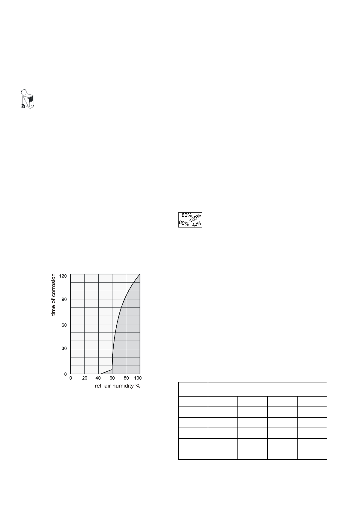
E.g. the following diagram shows in an exemplary way
the corrosion speed of metal at different air humidity
rates.
There are two different ways of drying the buildings:
1. By heating and exchanging the air:
The ambient air is heated to absorb humidity and to
be carried off to the outside. However, the total generated energy is lost with the carried off humid air.
2. By dehumidifying:
The humid air in the closed room is continuously de-
humidified according to the condensation principle.
Dehumidification has a decisive advantage regarding
energy consumption:
Energy is exclusively needed for the existing room volume. The mechanical heat released during the dehumidification process increases the room temperature
slightly.
When used correctly the air dehumidifier consumes
only approx. 25 % of the energy to be supplied according to the “heating and ventilation” principle.
Relative Air Humidity
Ambient air is a gas mixture and it always contains a
certain rate of water in the form of water vapour.
This percentage of water is indicated in g per kg of dry
air (absolute water content).
1 m³ of air weighs approx. 1.2 kg at 20° C.
Depending on the temperature each kg of air can only
absorb a defined quantity of water vapour. When this
quantity has been absorbed, the air is “saturated” and
has a relative humidity of 100 %.
By relative air humidity we understand the relation between the percentage of water vapour contained in the
air at the moment concerned and the maximum possible percentage of the water vapour, based on equal
temperatures.
The capacity of air to absorb water vapour increases
with raising temperatures. This means that the maximum possible (= absolute) water content is increased
with increasing temperatures.
As you can see the corrosion speed is insignificant at a
relative air humidity of less than 50 % and at a humidity
rate of less than 40 % it can even be neglected. When
the relative humidity exceeds 60 % corrosion speed increases considerably.
This limit regarding damages caused by humidity is also
applicable to many other materials, such as powdery
substances, packing materials, wood, and electronic
apparatuses.
4
Temp. °C
-5 1,3 1,9 2,6 3,3
+10 3,8 5,6 7,5 9,4
+15 5,1 7,7 10,2 12,8
+20 6,9 10,4 13,8 17,3
+25 9,2 13,8 18,4 23,0
+30 12,9 18,2 24,3 30,3
Water vapour content in g/m³ at an air humidity of
40% 60% 80% 100%
Water Vapour Condensation
+
+
The maximum possible percentage of water vapour
that can be absorbed becomes higher while the air is
heated, but the obtained percentage of water vapour
remains unchanged, and consequently the relative air
humidity is reduced.
However, when the air is cooled the maximum possible percentage of water vapour that can be absorbed
is continuously reduced, whereas the water vapour
quantity contained in the air remains unchanged, and
consequently the relative air humidity rises.
When the air is further cooled off the absorption capacity regarding the maximum possible water vapour
quantity is continuously reduced until it is equal to the
obtained percentage of water vapour. This is the dew
point temperature.
If the air is cooled down below the dew point, the obtained percentage of water vapour will be higher than
the maximum possible water vapour quantity.
Water vapour is deposited.
It condenses, is converted into water and thus is extracted from the air
Steamed up window panes in winter or
steamed up bottles containing cold drinks
are typical examples of condensation.
The higher the relative air humidity is, the
higher is the dew point temperature, and
consequently it is easier for the temperatures to fall below the dew point.
Material Drying
Building materials/buildings can absorb considerable
quantities of water; e.g. bricks 90-190 l/m³, heavy concrete 140-190 l/m³, calcareous sandstone 180-270 l/m³.
Humid materials such as brickwork dries in the following
way:
◊ The contained humidity flows from the
inside of the material to its surface
◊ Evaporation takes place on the sur-
face = water vapour is absorbed by the
ambient air.
◊ The air enriched with water vapour is continuously cir-
culating through the REMKO air dehumidifier. It is dehumidified and leaves the apparatus in a slightly
heated up state to absorb again water vapour.
◊ By this the humidity contained in the material is con-
tinuously reduced; the material becomes dry.
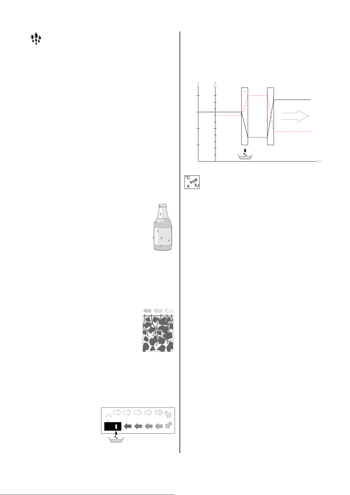
The air current is cooled off on its way through/via the
evaporator until its temperature falls below the dew
point. The water vapour condenses, it is collected in a
condensate trap and carried away.
°C
% r.F.
30
100
90
25
20
15
80
70
60
50
40
30
20
10
-
condenser evaporator
air-temperature
air-direction
humidity
course
Condensation Heat
The energy transferred from the condenser to the air
consists of:
◊ The heat that was previously extracted in the evapo-
rator.
◊ The electric driving energy.
◊ The condensation heat released by liquefying water
vapour.
When the liquid condition is converted into a gaseous
condition energy must flow back. This energy is called
evaporation heat. It does not cause the temperature to
raise but is used for the conversion from the liquid to
the gaseous state. On the other hand energy is released when gas is liquefied, and this energy is called
condensation heat.
The energy rate of evaporation and condensation heat
is identical.
For water this is 2250 kJ / kg ( 4,18 kJ = 1kcal )
This shows that a relatively high energy rate is released
through water vapour condensation.
If the humidity to be condensed is not generated by
evaporation within the room, but fed from the outside,
e.g. by aeration, the condensation heat released
thereby contributes to room heating.
When materials or rooms are to be dried the heat energy flows in a circulation, i.e. it is consumed during
evaporation and released during condensation.
A larger amount of heat energy is generated when fed
air is dehumidified, and this heat energy is expressed in
the form of a rise in temperature.
The generated condensate is collected in the
apparatus and carried
away.
Generally the time needed for drying does not depend
on the apparatus capacity, but it is determined by the
speed at which the material or the parts of the building
emit the humidity contained in them.
5
Safety Instructions
REMKO dehumidifiers will provide you with high utility
and long life thanks to our extensive material, function
and quality controls.
Dangers may arise nevertheless if the unit is used by
persons not familiar with its operation or if the unit is not
used for its intended purpose.
◊ Make sure to install and use the unit only in explo-
sion-proof rooms.
◊ Make sure not to install and use the unit in an atmos-
phere containing fuel, oil, sulphur and salt.
◊ Make sure to install the unit on a solid base and in a
vertical position.
◊ Make sure not to expose the unit to a direct water
jet.
◊ Make sure that the air can be freely sucked in and
blown off.
◊ Make sure that the suction side is always free from
dirt and loose objects.
◊ Never put objects into the unit.
◊ Do not cover the unit during operation.
◊ Make sure not to transport the unit during operation.
◊ Avoid strong vibrations on the unit as soon as there
is condensate in the condensate tank.
◊ Make sure to protect all electric cables outside the
unit from damage (e.g. by animals).
◊ Before installing connection cable extensions make
sure that they are suitable for the connected power,
cable length and the intended purpose.
◊ Make sure to empty the condensate tank before in-
stalling the unit in another place.
◊ Make sure to transport the unit only in a vertical posi-
tion.
◊ Damage on the compressor will be avoid by a wait-
ing period of at least 1 minutes before starting the
unit.
◊ Uses/operations other than that indicated in these
operating instructions are not allowed!
In the case of non-observation, any of our responsibilities and guarantees will become void.
Any work regarding the refrigerating plant and its
electrical equipment is to be carried out exclu-
G
sively by especially authorized experts!
Important Tip Regarding Recycling!
◊ The unit is to be used with the environmentally
friendly, ozone-neutral refrigerant R407C.
◊ The refrigerant/oil mixture in the unit is to be dis-
posed of correctly and in accordance with the legal
or local prescriptions.
Unit Description
These unit have been designed for automatic, universal
and problem-free air dehumidification. Thanks to their
compact dimensions they can be easily transported and
installed.
The unit work according to the condensation principle
and are equipped with a hermetically sealed refrigerating plant, a silent nearly maintenance-free ventilator as
well as with a connection cable with plug.
For an operation-control exists a green control-lamp
“operation” on the control-panel. The correct time of operation will record by a hour counter.
The fully automatic electronic control, the condensate
container with integrated overflow safety device, as well
as the connecting branch for direct condensation draining ensure trouble-free continuous operation.
The unit correspond to the fundamental safety and
health requirements of the relevant EC regulations, they
operate safely and are easy to handle.
Function
When the unit is switched on the electronic control and
monitoring starts.
The green control lamp is lit up.
The compressor and fan are switched on time-delayed.
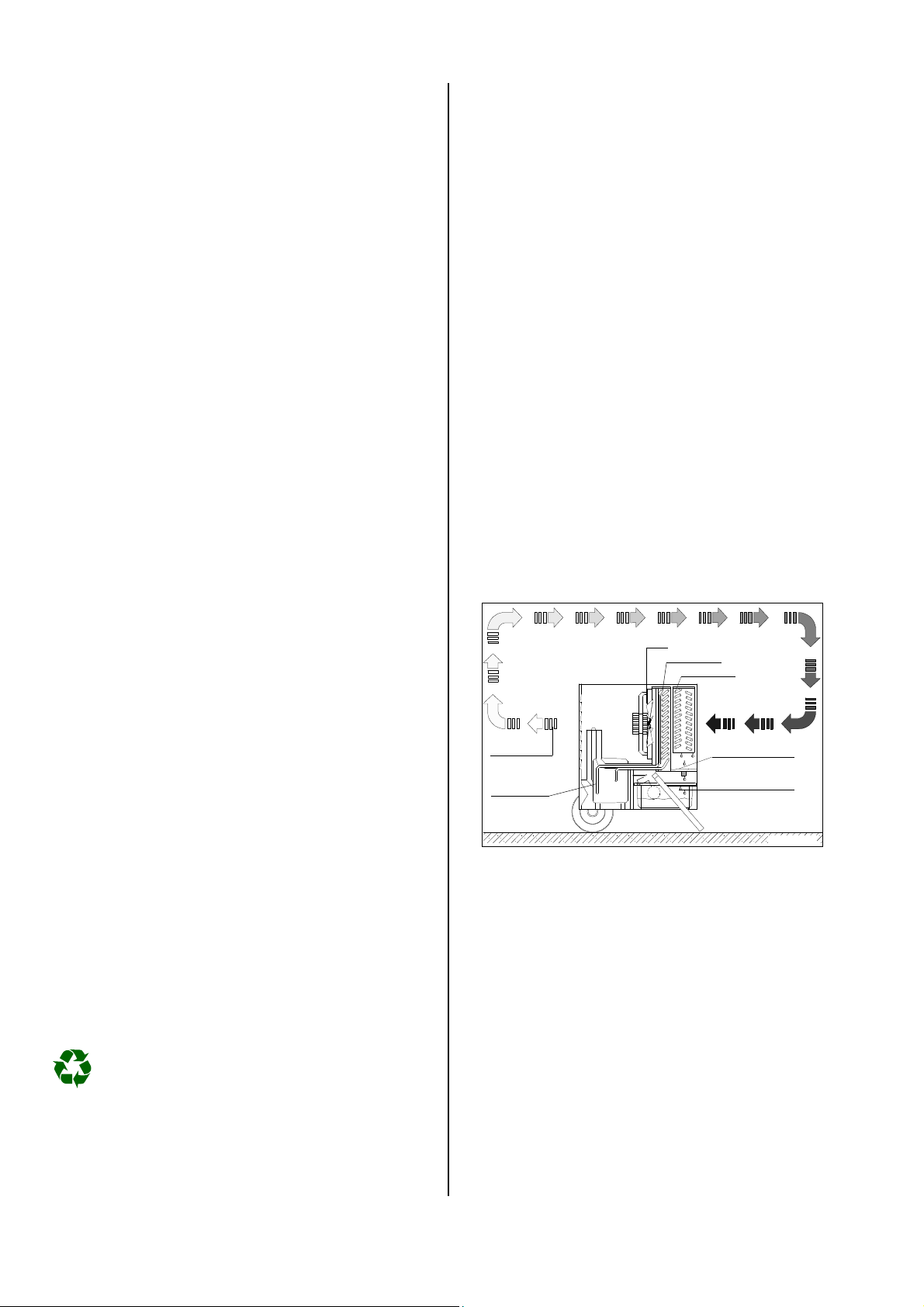
fan
condenser
evaporator
ambient air
dehumidified
ambient air
compressor
Schematic display of function
The fan sucks in the ambient air via the air filter, the
evaporator and the condenser placed behind the latter.
Heat is extracted from the ambient air at the cold
evaporator. It cools down below the dew point, and the
water vapour contained in the air is deposited as condensate or hair frost on the evaporator lamellas.
When necessary the evaporator is defrosted with hot
gas with temperature control.
The dehumidified cooled down air is reheated at the
condenser (heat exchanger), and then it is blown out
when it has reached a temperature of approx. 3 - 5 degrees above the ambient temperature.
The treated dry air is mixed with the ambient air.
Thanks to the continuous circulation of the ambient air
through the unit, the relative air humidity in the place of
installation is continuously reduced until it has reached
the desired value.
condensate trap
water container
fig. AMT 60
6

Unit Operation
The unit are equipped with a temperature-controlled hot
gas defrosting system. This system is equipped with a
feeler which has been mounted between the evaporator
lamellas.
When the formation of hair-frost on the evaporator increases, its heat absorption capacity is reduced due to
the insulating characteristics of the hair-frost. Consequently the temperature on the evaporator's surface
falls.
As soon as the temperature has fallen below a defined
minimum value, the refrigeration circulation is reset to
the defrosting position and dehumidification is interrupted for a short time.
As soon as the hair-frost (ice) has been defrosted and
temperature raises again at the sensor, the unit is reset
to the normal dehumidification operation.
When room temperature is high enough, lamella surface never becomes so cold as to allow the formation of
hair-frost; consequently defrosting is not necessary.
REMKO air dehumidifiers operate very economically.
Depending on the room temperature and the air humidity only approx. 30 or 40 % of electric energy are consumed for the cooling capacity of the unit.
The proper functioning of the unit cannot be guaranteed at temperatures below 10 °C or a relative
G
humidity of less than 40% r. h.
Working Range
Dehumidification performance depends exclusively
upon the design of the room, the room temperature, the
relative humidity and the correct observance of the
setup instructions.
The dehumidification performance increases with the
room temperature and relative humidity.
For a reliable operation the following working-range is
valid:
◊ Room temperature between 6 °C and 32 °C
◊ Relative humidity between 40% and 100% r. h.
◊ Do not install the unit directly near radiators or other
heat sources.
◊ Entering into and going out of the room should be
avoided if possible.
◊ Make sure to keep the room to be dried and
dehumidified closed, so that air from outside cannot
penetrate into it.
keep the
window
minimum distance of 0,5 m
closed
Please keep distance to the
radiator or other heating sources
keep the
door
closed
◊ You can obtain better air circulation if you place the
unit at a height of approx. 1 m.
◊ Make sure that appropriate measures for mainte-
nance and care are taken when the unit is installed
in dusty surroundings as well as in stables with ammoniacal atmosphere.
See chapter “Maintenance and Care”.
◊ The electrical connection of the unit is to be carried
out according to DIN VDE 0100, part 704. It is to be
connected to service entrances with residual current
operated device.
◊ If the unit is installed in washhouses, showers or
similar wet areas the user has to protect it by an adequate residual current operated device according to
the relevant regulations.
◊ Connection cable extensions may only be used
when they have been completely unrolled.
Installation
◊ Install the unit in a horizontal position to ensure the
trouble-free drainage of condensate.
◊ Install the unit in the middle of the room, if possible,
to ensure optimal air circulation.
◊ If this is not possible due to the conditions in the
building make sure that the air can be easily sucked
in at the front of the unit and blown off from its rear
part.
◊ Make sure to observe a minimum distance of 50 cm
Condensate
Depending on the air temperature and the relative air
humidity the condensed water drips either continuously
or only during the defrosting phases into the condensate
trap.
The condensate is drained via a connecting branch into
the water container (only in model AMT 60-E) or via a
hose into the discharge pipe installed at a lower level.
7

Operation with water container (only AMT 60-E)
Important Hints!
In the water container there is a floater which interrupts
the dehumidification operation by means of a microswitch when the container is full.
floater
When the unit has been switched off the evaporator can
further defrost through the ambient temperature.
Operation with hose connection (AMT 60-E)
The condensate trap is equipped with a hose nipple.
When the water container has been removed, a stan-
dard water hose (is not included in our delivery) can be
connected to the connecting branch.
The unit stops working.
The yellow control lamp on the
switchboard lights up.
Remove the filled container.
For this purpose lift the container slightly and then pull it
carefully forward to remove it.
You can empty the condensate
into a drain pipe or sink.
Make sure that condensate
does not continue dripping!
◊ When the container is reinstalled make sure that it is
in the correct position.
◊ Make sure not to damage the micro switch.
Operation with hose connection (AMT 90-E)
The unit AMT 90-E is equipped with a firmly installed
discharge hose. There several versions of discharging
the generated condensate:
Version A
The condensate is collected in
an adequately dimensioned receiver which is to be procured
by the user.
Make sure to empty and to control the receiver regularly.
Version B
The condensate is drained via a
hose extension piece into an
outlet which has been installed
at a lower level.
This offers the possibility of continuous operation without control.
condensate trap
hose nipple
microswitch
drain hose
◊ When the unit is in uncontrolled continuous opera-
tion, the condensate should be drained into a discharge pipe or sink installed at a lower level.
Make sure that the discharge hose is installed to
a lower level, in such a way as to ensure unhindered drainage of condensate from the conden-
G
sate tank.
Installation of the water container (only AMT 60-E)
We recommend cleaning of the container with a clean
cloth after its removal.
floater
strap
The cleaned container
is to be carefully reinstalled into the unit.
The strap of the floater
has to face the inside of
the unit.
Observe sticker.
Version C
The condensate can be col-
lected first in a receiver as described under Version A and
then be fed by means of a small
submerged pump either to an
outlet installed at a higher level
or to the outside.
If there is no outlet at a lower
lever and no discharge pipe.
Starting
The filter of the unit is to be controlled and cleaned thoroughly before every use. If the air suction grille is dirty,
please cleaned it up like shown in chapter ”Maintenance
and Service”.
1. Introduce the main plug into a properly protected plug socket.
230V/1~ 50 Hz / fuse 16 A
2. Put main switch into position „I”.
Green control lamp “operation” is lit
up.
3. Please note: the unit is switched on
time-delayed and then goes into the
continuous operation mode.
8

Operation with Hygrostat
The REMKO hygrostat (accessory) is supplied with a
special intermediate plug.
1. Insert intermediate plug into a properly protected
plug socket.
2. Position hygrostat in an adequate place within the
room to be dehumidified.
Not directly near the unit.
3. Connect the unit plug with the intermediate plug.
4. Put main switch of the unit into
position “I”.
5. Pre select the desired humidity by
setting the hygrostat.
Transport Instructions
The unit is equipped with 2 wheels and an easily removable transport handle to ensure safe transport.
1. Switch off the unit prior to changing its place and to
remove the mains plug from the plug socket.
2. After that empty the condensate container.
3. Make sure to transport and store the unit only in a
vertical position as long as there is still humidity at
the evaporator, in the condensate trap and in the
condensate container.
Do not use the cable to pull the unit!
G
The unit is automatically switched on if the humidity rate
in the room is higher than the previously set value.
The unit operates fully automatically until the preselected relative air humidity has been reached or until the
unit (only model AMT 60-E) has been switched off by
the floater in the water container. In such a case the yellow control lamp is lit up.
If the unit is switched off manually or by the
hygrostat or by the floater in the water container,
it is only restarted after approx. 1 minute.
G
This safety measure is necessary to avoid damages of the compressor.
Discard the Unit
Put the operating switch into “0”
position.
Maintenance and Service
Regular care and the observation of a number of basic
rules will ensure the dehumidifier’s long life and reliable
operation.
The complete cooling system is hermetically sealed and
contains no user-serviceable parts. It may only be serviced by authorised repair facilities. All moving parts feature low-maintenance long-life lubrication.
The unit should be inspected and cleaned thoroughly after each long period of operation, at a minimum once a
year. Please note the following points:
◊ Ensure that the interior and exterior of the unit re-
mains free of dust and other deposits.
◊ Clean the unit only with a dry or dampened cloth.
Do not use a water jet.
◊ Do not use aggressive cleansers or cleaning prod-
ucts containing solvents.
◊ Regularly check the dust filter and the exhaust grille
for soiling and clean them as required.
Replace the dust filter as required.
Dust Filter Cleaning
Prior to longer operating breaks or pauses:
1. Remove the mains plug from the plug socket (or
transitional socket).
2. Empty the condensate container and dry it with a
clean cloth.
3. Make sure that no condensate continues to drop or drip!
When the unit has been switched off the evaporator
can further defrost through the ambient temperature.
4. Clean the dust filter according to the given instructions.
5. Protect the unit, possibly with a plastic cover, and
store it in a vertical position in a safe place.
◊ Lift the air suction grille slightly and remove it pulling
towards and downwards.
◊ Then remove the dust filter.
◊ Slight o insignificant dirt is to be cleaned by blowing
out or vacuum-cleaning the dust filter carefully.
◊ If the dust filter is very dirty it is to be washed with a
lukewarm soap solution (max. 40° C) and then to be
rinsed with clear water.
◊ Make sure that the dust filter is completely dry and
undamaged before you reinstall it.
◊ In case of extreme dirt the dust filter is to be replace.
◊ Never use the unit without installed dust filter!
Works at refrigerating plant and at electrical equipment is to be carried out only by an especially
G
authorised service company!
9

Condenser and Evaporator Cleaning
Dismount the casing of the unit before cleaning up the
condenser and evaporator.
The following maintenance have to be carried out only
by an especially authorised service company!
Make sure to remove the mains plug from the plug
socket before you carry out any of the described
G
measures or work!
A
B B
Clean the unit like the following description:
1. Remove the mains plug from the plug socket.
2. Unscrew 2 fastening screws A and remove the
transport strap.
3. Unscrew 4 fastening screws B and remove the casing of the unit towards the top.
4. The lamellas of the condenser are either to be
blown out, to be vacuum-cleaned or to be cleaned
with a soft brush.
5. Please clean the condensator very carefully - the
fine aluminium lamellas can be easily deformed!
Sharp-edged lamellas survives injury-danger !
G
6. Do not clean with a water jet.
7. Clean evaporator lamellas with a lukewarm soap
solution.
8. Rinse with clean water to remove any remaining
soap residues.
9. Clean carefully the inner or internal surfaces of the
unit as well as the fan wing.
10. After that, dry with a clean cloth.
11. Mount all the parts in the reverse order.
12. Test the functions of the unit and perform an electrical safety check!
In Case of Troubles
This unit has been designed based on state of the art
manufacturing methods and it has been tested repeatedly as to its perfect function.
However, if there are any operating troubles check the
unit according to the following listing:
The unit does not start:
◊ Control or check operating switch.
The green control lamp must be lit.
◊ Check connection to the mains.
230V/1 – 50 Hz.
◊ Check mains fuse at user.
10A resp. 16A.
◊ Check mains plugs.
◊ Check filling level of water container and/or check
correct installation.
Only AMT 60-E.
◊ Check micro switch function.
Only AMT 60-E.
◊ Control hygrostat (accessory) setting.
The set value must be lower than the relative air humidity in the room where the unit has been installed.
◊ Check intermediate plug of hygrostat to see whether
it has been damaged and whether it has been correctly plugged in.
Red Control lamp is lit (fault):
◊ The system is either overloaded or overheated.
◊ Find out cause of fault before restarting apparatus.
◊ Restart is carried out automatically when apparatus
has cooled down.
Unit runs, but no condensate formation:
◊ Control ambient temperature. The unit operates
within a temperature range from 3° C to 32° C.
◊ Control air humidity.
Min. 40% relative humidity.
◊ Check hygrostat setting and set a lower value, if
necessary.
◊ Check whether dust filter is dirty, if so, clean it.
◊ Check whether the evaporator and condenser lamel-
las are dirty and clean them, if necessary.
◊ The evaporator is covered with ice. Check whether
automatic defrosting device operates correctly, or
check ambient temperature.
◊ Evaporator temperature is not lower than the room
temperature. Control automatic defrosting device
and compressor, respectively.
If the unit does not work correctly in spite of the controls
or checks inform an authorised service company.
10

Technical Data
Model AMT 60-E AMT 90-E
Working range - temperature °C 3 - 32 3 - 32
Working range - humidity % r.h. 40 - 100 40 - 100
Dehumidifying capacity, max. l/day 64 93
Dehumidifying capacity at 30°C / 80% r.h l/day 54,2 79,8
Dehumidifying capacity at 20°C / 70% r.h. l/day 34,9 43,1
Dehumidifying capacity at 10°C / 60% r.h. l/day 11,3 16,3
Capacity water container litres 7,5 –––––
Cooling capacity at 5°C tv / 45°C tk
kW 2,86 4,36
Air volume m³/h 765 1050
Refrigerant (FCKW -free) R 407 C R 407 C
Refrigerant quantity g 575 1600
Power supply 1~ V 230 230
Frequency Hz 50 50
Rated current consumption, max. A 4,1 6,9
Power consumption, max. kW 0,94 1,56
Power consumption at 20°C / 70% r.F. kW 0,691 0,978
Fuse protection (required) A 10 16
Sound pressure level L
pA 1m
1)
dB (A) 60 68
Dimensions total depth mm 720 (635) 700 (630)
total width mm 590 740
total height mm 880 (720) 970 (855)
Weight kg 48 63
1) Noise measuring DIN 45635 - 13 - KL 3
( ) Dimensions without transport handle
Any mode of operation other than specified in these operating instructions is not permissible!
Failing to observe it causes the customer to lose all rights to guarantee or damage claims.
Any claims under guarantee regarding materials can be accepted only when the orderer or his customer has
filled in completely the “guarantee certificate” which is enclosed with every REMKO-device and has
returned it to REMKO GmbH & Co. KG in due time after the unit’s sale and commissioning.
11

Exploded View AMT 60-E
1 2 3 4
5
6
7
38
37
39
36
35
34
33
13
14
8 9 10
12
15
11
16
17
18
19
12
32
26
25
24
31
We reserve the right to make modifications in dimensions and construction in the interests of technical progress.
27 28 29 30
22
23
20
21

Spare Part List AMT 60-E
No. Designation Ref.-No.
1 air suction grille 1105501
2 dust filter 1105551
3 filter fixture 1105503
4 housing 1105504
5 transport handle (upper part) 1105552
6 blow out grille 1105506
7 heat-exchanger-package, cpl. 1105553
8 fan blade 1105554
9 clutch plate 1101155
10 fan motor 1105555
11 motor fixture 1105556
12 solenoid valve 1105508
13 liquid line dryer 1101056
14 cover/electric panel 1105557
15 compressor 1105558
16 control panel 1105559
17 control lamp, yellow 1105512
18 control lamp, red 1105513
19 control lamp, green 1105514
20 running hour meter 1105515
21 main switch 1102248
22 main fuse 1105561
23 fuse holder 1105560
24 electric cable 1101076
25 cable relief 1101047
26 axle 1105516
27 wheel 1102155
28 wheel lock ring 1101622
29 wheel cap 1101623
30 rubber stopper, large 1105550
31 handle, lower part 1105523
32 bottom plate 1105562
33 running capacitor 1105563
34 electric panel 1105564
35 micro-switch 1108061
36 PCB with control 1105565
37 floater 1101034
38 water container, cpl. 1108072
39 drip tray 1105566
not shown hose nipple 3/8" x 12 1105567
temperature sensor (orange) 1105526
temperature sensor (blue) 1105527
When ordering spare parts please indicate ref.-no. and machine no. (see typeplate)!
13

Exploded View AMT 90-E
1 2 3 4
5
6
38
37
36
39
35
7
34
33
8
9
10 11 12 13
14
15
16
17
18
19
20
21
25 26 27
22
23
24
14
29 28 30 31 32
We reserve the right to make modifications in dimensions and construction in the interests of technical progress.

Spare Part List AMT 90-E
No. Designation Ref.-No.
1 air suction grille 1105581
2 dust filter 1105568
3 filter fixture 1105569
4 housing 1105533
5 transport handle (upper part) 1105534
6 blow out grille 1105536
7 expansion valve 1105570
8 heat-exchanger-package, cpl. 1105571
9 solenoid valve 1105572
10 fan blade 1105573
11 clutch plate 1101155
12 fan motor 1105574
13 motor fixture 1105556
14 compressor 1105575
15 collector 1105576
16 liquid line dryer 1105577
17 control panel 1105578
18 control lamp, red 1105513
19 control lamp, green 1105514
20 running hour meter 1105515
21 main switch 1102248
22 main fuse 1105561
23 fuse holder 1105560
24 electric cable 1101076
25 cable relief 1101047
26 electric panel 1105564
27 axle 1105540
28 wheel 1101621
29 wheel lock ring 1101622
30 wheel cap 1101623
31 rubber stopper, large 1105550
32 handle, lower part 1105541
33 running capacitor 1105563
34 PCB with control 1105565
35 cover/electric panel 1105557
36 bottom plate 1105579
37 drainage hose 1105547
38 hose nipple 1105546
39 drip tray 1105580
not shown temperature sensor (orange) 1105526
temperature sensor (blue) 1105527
When ordering spare parts please indicate ref.-no. and machine no. (see typeplate)!
15

Wiring Diagram AMT 60-E
CONTROL BOARD
MAINS COMPR. VALVE FAN COND.
NTC
EVAP.
NTC
1 2 3 4 5 6 7 8 20 21 22 23 24 25
2 4
S2
F1
8,2 A
1
5 2
H1
yellow
H2
green
OP
C
P1
h
L1 N
R
S
M1
C1
Y1
L1 N
M
1~
M2
R1
red
R2
blue
S1
4 1
FAIL
LAMP
H3
red
L1 N PE
230V/1~ 50Hz
C1 = Capacitor
F1 = Main fuse
H1 = Control lamp, yellow (tank full)
H2 = Control lamp, green (operation)
H3 = Control lamp, red (fault)
M1 = Compressor
M2 = Fan motor
We reserve the right to make modifications in dimensions and construction in the interests of technical progress.
OP = Overload protection, compressor
P1 = Running hour meter
R1 = Temperature sensor (red)
R2 = Temperature sensor (blue)
S1 = Main switch
S2 = Micro switch, water container
Y1 = Solenoid valve
16

Wiring Diagram AMT 90-E
CONTROL BOARD
MAINS COMPR. VALVE FAN COND.
NTC
EVAP.
NTC
1 2 3 4 5 6 7 8 20 21 22 23 24 25
F1
8,2 A
5 2
H2
green
OP
C
P1
h
L1 N
R
S
M1
C1
Y1
L1 N
M
1~
M2
R1
red
R2
blue
S1
4 1
FAIL
LAMP
H3
red
L1 N PE
230V/1~ 50Hz
C1 = Capacitor
F1 = Main fuse
H2 = Control lamp, green (operation)
H3 = Control lamp, red (fault)
M1 = Compressor
M2 = Fan motor
We reserve the right to make modifications in dimensions and construction in the interests of technical progress.
OP = Overload protection, compressor
P1 = Running hour meter
R1 = Temperature sensor (red)
R2 = Temperature sensor (blue)
S1 = Main switch
Y1 = Solenoid valve
17

Maintenance and Service Log
Model: ................................ Model No.: ......................................
1 2 3 4 5 6 7 8 9 10 11 12 13 14 15 16 17 18 19 20
Clean device -surfaceClean device -interiorClean condenser
Clean evaporator
Clean fan blade
Clean/replace dust filter
Check protection guards
Check device for damage
Check all fixing screws
Electric safety-inspections
Test run
Remarks: ......................................................................................................................................................................
......................................................................................................................................................................................
1. Date: ...................... 2. Date: ...................... 3. Date: ...................... 4. Date: ...................... 5. Date: ......................
.................................. ................................... ................................... ................................... ...................................
Signature Signature Signature Signature Signature
6. Date: ...................... 7. Date: ...................... 8. Date: ...................... 9. Date: ...................... 10. Date: ....................
.................................. ................................... ................................... ................................... ...................................
Signature Signature Signature Signature Signature
11. Date: .................... 12. Date: .................... 13. Date: .................... 14. Date: .................... 15. Date: ....................
.................................. ................................... ................................... ................................... ...................................
Signature Signature Signature Signature Signature
16. Date: .................... 17. Date: .................... 18. Date: .................... 19. Date: .................... 20. Date: ....................
.................................. ................................... ................................... ................................... ...................................
Signature Signature Signature Signature Signature
18
Device must be maintained according to legal regulations by authorised personnel only!


REMKO GmbH & Co. KG
Klima- und Wärmetechnik
D-32791 Lage • Im Seelenkamp 12
D-32777 Lage • PO Box 1827
Phone +49 (5232) 606 - 0
Fax +49 (5232) 606260
 Loading...