

Remington RM4040, RM4040B Operating Manual
Operator’s Manual
ORIGINAL INSTRUCTIONS
RM4040 / RM4040B
Cordless Chain Saw
BC
SAVE THESE INSTRUCTIONS
IMPORTANT: Read this manual thoroughly before using this product. Follow all instructions.
769-12208 / 01 03/18
TABLE OF CONTENTS
Service . . . . . . . . . . . . . . . . . . . . . . . . . . . . . . . . . . . . . . . . . . . . . .2
Safety . . . . . . . . . . . . . . . . . . . . . . . . . . . . . . . . . . . . . . . . . . . . . . .2
Know Your Unit . . . . . . . . . . . . . . . . . . . . . . . . . . . . . . . . . . . . . . .10
Essential Terms and Definitions . . . . . . . . . . . . . . . . . . . . . . . . . .12
Specifications . . . . . . . . . . . . . . . . . . . . . . . . . . . . . . . . . . . . . . . .13
Assembly . . . . . . . . . . . . . . . . . . . . . . . . . . . . . . . . . . . . . . . . . . . .13
Starting and Stopping . . . . . . . . . . . . . . . . . . . . . . . . . . . . . . . . . .15
Operation . . . . . . . . . . . . . . . . . . . . . . . . . . . . . . . . . . . . . . . . . . .16
Maintenance . . . . . . . . . . . . . . . . . . . . . . . . . . . . . . . . . . . . . . . . .22
Cleaning and Storage . . . . . . . . . . . . . . . . . . . . . . . . . . . . . . . . . .27
Troubleshooting . . . . . . . . . . . . . . . . . . . . . . . . . . . . . . . . . . . . . .28
Warranty . . . . . . . . . . . . . . . . . . . . . . . . . . . . . . . . . . . . . . . . . . . .29
NOTE: This operator's manual covers multiple models. Features
may vary by model. Not all features in this manual are applicable
to all models. The model depicted may differ from yours.
All information, illustrations, and specifications in this manual are based
on the latest product information available at the time of printing. We
reserve the right to make changes
he product may vary slightly from the illustrations contained in this
T
manual.
Copyright© 2017 MTD SOUTHWEST INC, All Rights Reserved.
at any time without notice.
SERVICE
DO NOT RETURN THIS UNIT TO THE RETAILER. PROOF OF
PURCHASE WILL BE REQUIRED FOR WARRANTY SERVICE.
For assistance regarding the assembly, operation or maintenance of
the unit, please call 1-866-206-2707 (in the United States) or 1-877-
696-5533 (in Canada). Additional information can be found at
www.remingtonpowertools.com.
Warranty service is available through an authorized service center.
To locate a servi
call the number listed above. Service on this unit, both within and
after the warranty period, should only be performed by an
authorized and approved service center. When servicing, use only
identical replacement parts.
ce center in your are
a, please visit our website or
The purpose of safety symbols is to attract your attention to
possible dangers. The safety symbols, and their explanations,
deserve your careful attention and understanding. The safety
warnings do not by themselves eliminate any danger. The
instructions or warnings they give are not substitutes for proper
accident prevention measures.
SYMBOL MEANING
DANGER:
Failure to obey a safety DANGER symbol WILL result in
serious injury or death to yourself or to others.
WARNING:
Failure to obey a safety WARNING symbol CAN result in
serious injury to yourself or to others.
Signals an EXTREME hazard.
Signals a SERIOUS hazard.
CAUTION:Signals a MODERATE hazard.
Failure to obey a safety CAUTION symbol MAY result in
property damage or injury to yourself or to others.
NOTE: Advises you of information or instructions vital to the
operation or maintenance of the equipment.
SAFETY
Read the operator’s manual and follow all warnings and safety
instructions. Failure to do so can result in serious injury to the
operator and/or bystanders.
CALIFORNIA PROPOSITION 65
WARNING:
chemical known to the State of California to cause cancer,
birth defects or other reproductive harm.
This product contains a
2

• IMPORTANT SAFETY INSTRUCTIONS •
GENERAL POWER TOOL SAFETY WARNINGS
WARNING:
instructions. Failure to follow the warnings and instructions
may result in electric shock, fire and/or serious injury.
Save all warnings and instructions for future reference.
The term “power tool” in the warnings refers to your mains-operated
(corded) power tool or battery-operated (cordless) power tool.
1) Work Area Safety
a) Keep work area clean and well lit. Cluttered or dark areas
invite accidents.
b) Do not operate power tools in explosive atmospheres
s in the presence of flammable liquids, gases or dust.
a
Power tools create sparks which may ignite the dust or fumes.
c) Keep children and bystanders away while operating a
power tool. Distractions can cause you to lose control.
2) Electrical Safety
a) Power tool plugs must match the outlet. Never modify the
plug in any way. Do not use any adapter plugs with
earthed (grounded) power tools. Unmodified p
atching outlets will reduce risk of electric shock.
m
b) Avoid body contact with earthed or grounded surfaces
such as pipes, radiators, ranges and refrigerators. There is
an increased risk of electric shock if your body is earthed or
grounded.
c) Do not expose power tools to rain or wet conditions. Water
entering a power tool will increase the risk of electric shock.
d) Do not abuse the cord. Never use
pulling or unplugging the power tool. Keep cord away from
heat, oil, sharp edges or moving parts. Damaged or
entangled cords increase the risk of electric shock.
e) When operating a power tool outdoors, use an extension
cord suitable for outdoor use. Use of a cord suitable for
outdoor use reduces the risk of electric shock.
f) If operating a power tool in a damp location is unavoidabl
se a ground fault circuit interrupter (GFCI) protected
u
supply. Use of a GFCI reduces the risk of electric shock.
3) Personal Safety
a) Stay alert, watch what you are doing and use common
sense when operating a power tool. Do not use a power
tool while you are tired or under the influence of drugs,
alcohol or medication. A moment of inattention while
operating power tools may result in serious personal i
) Use personal protective equipment. Always wear eye
b
protection. Protective equipment such as dust mask, non-skid
safety shoes, hard hat, or hearing protection used for
appropriate conditions will reduce personal injuries.
c) Prevent unintentional starting. Ensure the switch is in the
off-position before connecting to power source and/or
battery pack, picking up or carrying the tool. Carrying
power to
tools that have the switch on invites accidents.
d) Remove any adjusting key or wrench before turning the
power tool on. A wrench or a key left attached to a rotating
part of the power tool may result in personal injury.
e) Do not overreach. Keep proper footing and balance at all
times. This enables better control of the power tool in
unexpected situatio
ols with your finger on the switch or energ
ns.
Read all safety warnings and all
, such
lugs and
the cord
for carrying,
njury.
izing power
f) Dress properly. Do not wear loose clothing or jewelry.
Keep your hair, clothing and gloves away from moving
parts. Loose clothes, jewelry or long hair can be caught in
moving parts.
g) If devices are provided for the connection of dust
extraction and collection facilities, ensure these are
connected and properly used. Use of dust collection can
reduce dust-related hazards.
4) Power Tool Use and Care
a) Do no
b) Do not use the power tool if the switch does not turn it on
c) Disconnect the plug from the power source and/or the
d) Store idle power tools out of the reach of children and do
e) Maintain power
f) Keep cutting tools sharp and clean. Properly maintained
g) Us
e,
5) Battery tool use and care
a) Recharge only with the charger specified by the
b) Use power tools only with specifically designated battery
c) When battery pack is not in use, keep it away from other
d) Under abusive conditions, liquid may be ejected from the
6) Service
a) Have your power tool serviced by a qualified repair person
t forc
for your application. The correct power tool will do the job
better and safer at the rate for which it was designed.
and off. Any power tool that cannot be controlled with the
switch is dangerous and must be repaired.
battery pack from the p
adjustments, changing accessories, or storing power
tools. Such preventive safety measures reduce the risk of
starting the power tool accidentally.
not allow persons unfamiliar with the power tool or these
instructions to operate the power tool. Power tools are
dangerous in the hands of untrained users.
f moving parts, breakage of parts and any other
o
condition that may affect the power tool’s operation. If
damaged, have the power tool repaired before use. Many
accidents are caused by poorly maintained power tools.
cutting tools with sharp cutting edges are less likely to bind
and are easier to control.
e the power tool, accessories and tool bits etc. in
ccordance with these instructions, taking into account
a
the working conditions and the work to be performed. Use
of the power tool for operations different from those intended
could result in a hazardous situation.
manufacturer. A charger that is suitable for one type of
battery
pack may cre
battery pack.
packs. Use of any other battery packs may create a risk of
injury and fire.
metal objects, like paper clips, coins, keys, nails, screws
or other small metal objects, that can make a connection
from one terminal to another
together may cause burns or a fire.
battery; avoid contact. If contact accidentally occurs, flush
with water. If liquid contacts eyes, additionally seek
medical help. Liquid ejected from the battery may cause
irritation or burns.
using only identi
the safety of the power tool is maintained.
e the power tool. Use the correct power tool
ower tool before
tools. Check for misalignment or binding
ate a risk of fire when used with another
horting the battery terminals
. S
cal re
placement parts. This will ensure that
making any
3
Chain saw safety warnings:
• Keep all parts of the body away from the saw chain when
the chain saw is operating. Before you start the chain saw,
make sure the saw chain is not contacting anything. A
moment of inattention while operating chain saws may cause
entanglement of your clothing or body with the saw chain.
• Always hold the chain saw with your right hand on the rear
handle and your left hand on the
chain saw with a reversed hand configuration increases the
risk of personal injury and should never be done.
• Hold the power tool by insulated gripping surfaces only,
because the saw chain may contact hidden wiring. Saw chains
contacting a “live” wire may make exposed metal parts of the
power tool “live” and could give the operator an electric shock.
• Wear safety glasses and hear
protective equipment for head, hands, legs and feet is
recommended. Adequate protective clothing will reduce
personal injury by flying debris or accidental contact with the
saw chain.
• Do not operate a chain saw in a tree. Operation of a chain
saw while up in a tree may result in personal injury.
• Always keep proper footing and operate the chain saw
only when standing on fixed, secur
lippery or unstable surfaces such as ladders may cause a
S
loss of balance or control of the chain saw.
• When cutting a limb that is under tension be alert for
spring back. When the tension in the wood fibers is released
the spring loaded limb may strike the operator and/or throw
the chain saw out of control.
• Use extreme caution when cutting brush and saplings. The
slender material may
oward you or pull you off balance.
t
• Carry the chain saw by the front handle with the chain saw
switched off and away from your body. When transporting
or storing the chain saw always fit the guide bar cover.
Proper handling of the chain saw will reduce the likelihood of
accidental contact with the moving saw chain.
• Follow instructions for lubricating, chain tensioning
hanging accessories. Improperly tensioned or lubricated
c
chain may either break or increase the chance of kickback.
• Keep handles dry, clean, and free from oil and grease.
Greasy, oily handles are slippery causing loss of control.
• Cut wood only. Do not use chain saw for purposes not
intended. For example: do not use chain saw for cutting
plastic, masonry or non-wood building materials. Use of
the chai
result in a hazardous situation.
Causes and operator prevention of kickback:
Kickback may occur when the nose or tip of the guide bar touches
an object, or when the wood closes in and pinches the saw chain in
the cut.
Tip contact in some cases may cause a sudden reverse reaction,
kicking the guide bar up and back towards the operator.
Pinching the saw cha
uide bar rapidly back towards the operator.
g
Either of these reactions may cause you to lose control of the saw
which could result in serious personal injury. Do not rely exclusively
upon the safety devices built into your saw. As a chain saw user,
you should take several steps to keep your cutting jobs free from
accident or injury.
Kickback is the result of
procedures or conditions and can be avoided by taking proper
precautions as give below:
n saw for operations diff
catch the saw chain and be whipped
in along the top of the guide bar may push the
tool misuse and/or incorre
nt handle. Holding the
fro
tection. Further
ing pro
e and level surface.
erent than intended could
ct operating
and
• Maintain a firm grip, with thumbs and fingers encircling
the chain saw handles, with both hands on the saw and
position your body and arm to allow you to resist kickback
forces. Kickback forces can be controlled by the operator, if
proper precautions are taken. Do not let go of
o not overreach and do not cut above shoulder height.
• D
This helps prevent unintended tip contact and enables better
control of the chain saw in unexpected situations.
• Only use replacement bars and chains specified by the
manufacturer. Incorrect replacement bars and chains may
cause chain breakage and/or kickback.
• Follow the manufacturer’s sharpening and maintenance
instructions for the sa
height can lead to increased kickback.
w chain. D
ecreasing the depth gauge
the chain saw.
WARNING:Read all safety warnings and all
instructions. Failure to follow the warnings and instructions
may result in electric shock, fire and/or serious injury.
READ ALL INSTRUCTIONS BEFORE OPERATING
1. SAVE THESE INSTRUCTIONS - This manual contains
important safety and operating instructions.
2. Before using this product, read all instructions and cautionary
markings on the battery, battery charger, and the unit(s) powered
by the battery.
3. Do not handle the charger, including the charger plug and
charger terminals, with wet hands.
4. Do not charge the unit outdoors.
WARNING:
RM4150 batteries with this unit. DO NOT use any other type
of battery, attachment or accessory with this unit. Other
types of batteries, attachments or accessories could lead to
serious injury, property damage or damage to the unit.
NOTE: Although this unit can use the RM4130 battery, it is
not recommended. For best performance, always use an
RM4140 or RM4150 battery with
Only use RM4130, RM4140 or
this unit.
WARNING:Only charge RM4130, RM4140
or RM4150 batteries with an RM4110 battery charger. DO
NOT attempt to use any other battery charger to charge
RM4130, RM4140 or RM4150 batteries. Other types of
battery chargers may cause the batteries to burst, resulting
in fire, personal injury or property damage.
WARNING:
charger to charge RM4130, RM4140 or RM4150 batteries.
DO NOT attempt to charge any other batteries with an
RM4110 battery charger. Other types of batteries may
burst, causing fire, personal injury or property damage.
Only use an RM4110 battery
4
GENERAL SAFETY WARNINGS
• Read the instructions carefully. Be familiar with the controls and
proper use of the unit. Know how to stop the unit and disengage
the controls quickly.
• Stay alert. Do not operate this unit when tired, ill or under the
influence of alcohol, drugs or medication.
• Never allow children to operate the unit. Teens must be trained,
accompanied and supervised by an adult. Never allow
perate the unit without proper instruction.
o
• All guards and safety attachments must be installed properly
before operating the unit.
• Inspect the unit before use. Check for damaged parts. Make sure
all parts operate properly. Make sure all fasteners are in place
and secure. Make sure all moving parts are properly aligned and
are not bound. Replace parts that are cracked, chipped, or
damaged in
parts repaired or replaced by an authorized service center. Do
not operate the unit with loose or damaged parts.
• Be aware of risk of injury to the head, hands and feet.
• Carefully inspect the area before starting the unit. Remove
rocks, broken glass, nails, wire, string and other objects that
may be thrown or become entangled with the unit.
• Clear the a
outside a 50-foot (15 m) radius, at a minimum. Even then, they are
still at risk from thrown objects. Encourage bystanders to wear
eye protection. If you are approached, stop the unit immediately.
• This unit is intended for occasional, household use only.
• Do not allow the unit to be used as a toy.
any way.
a of children, bystanders and pets; keep them
re
Have all damaged or improperly working
adults to
SAFETY WARNINGS FOR ELECTRIC UNITS
General Electric Safety
• Do not expose the unit to rain or wet conditions. Store
indoors.
• Do not handle the unit with wet hands.
• Avoid dangerous environments. Do not operate the unit in the
rain, in wet conditions or on wet surfaces. Moisture is a shock
hazard.
• To reduce the risk of electric shock, avoid body contact with
grounded conductors, such as metal pipes or wire fences.
• Do not operate the unit in explosive atmo
presence of flammable liquids, gases or dust.
Battery Charger Safety
• Follow all charging instructions. Do not charge the battery
outside the temperature range specified in these instructions.
Improperly charging the battery or charging the battery outside
of the specified temperature range may damage the battery and
increase the risk of fire.
• A nameplate on the unit indicates the
onnect the unit to an AC voltage that differs from this voltage.
c
• An extension cord should not be used unless absolutely
necessary. Use of an improper extension cord could result in a
risk of fire, electric shock or electrocution.
• Do not use multiple extension cords.
• Make sure the extension cord is heavy enough to carry the
current drawn by the unit. An undersized extension cord
cause a drop i
overheating. If in doubt, use the next heavier gauge cord. The
smaller the gauge number, the heavier the cord.
n line voltage, resulting in a loss of power and
sphere
voltage used. Never
the unit
s, such as in the
will
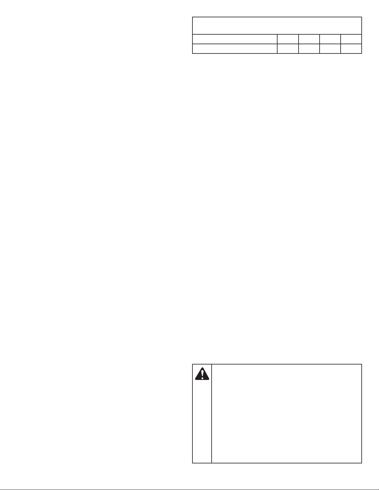
MINIMUM WIRE SIZE FOR EXTENSION CORDS FOR
120 VOLT APPLIANCES USING 0-6 AMPS
Cord Length (ft.) 25 50 100 150
Wire Size (AWG) 16 16 16 14
• Make sure the cords are in good condition. Inspect the power
cord and extension cord periodically. Look closely for
deterioration, cuts or cracks in the insulation. If a cord is
damaged in any manner while plugged in, disconnect the cord
from both the outlet and the unit. Do not use a damaged cord.
Damaged cords should be repaired or replaced.
• Do not abuse cords. Never pull or carry the unit by a cord
ords away from heat, oil, water, sharp edges, and moving
c
objects. Always grasp the plug when disconnecting a cord.
• Never modify a plug, cord or outlet in any way.
• Ground Fault Circuit Interrupter (GFCI) protection should be
provided on the circuit(s) or outlet(s) to be used with this unit.
For an extra measure of safety, use receptacles with built-in
GFCI protection.
• Do not place the battery ch
on, tripped over or subjected to damage.
• Do not charge batteries in the rain or in wet conditions. Keep the
battery charger in a cool and dry area.
• Keep the battery charger away from all liquid.
• Do not allow small metal items or material such as steel wool,
aluminum foil or other foreign particles into the charger port.
• Do not probe the charger with conductive mater
risk of electric shock.
• Do not cover the battery charger. The battery charger may
overheat.
• Do not allow the battery or battery charger to overheat. If they
are warm, allow them to cool down. Only charge batteries in
temperatures between 32° and 104° F (0° and 40° C).
• Always unplug the battery charger before cleaning it. Always
unplug the battery charger when it is not in use.
Battery Sa
• Do not expose the battery to fire or to temperatures over 176º F
(80º C). Doing so could cause an explosion.
• Handle batteries with care. Do not short the battery with
conductive materials, such as rings, bracelets, keys, etc.
Shorting the battery may cause personal injury, damage to the
battery or a fire.
• When the battery is not in use, keep it away from small metal
objects, such as paper clips, c
c
• Do not attempt to charge a cracked or damaged battery.
• Do not use a damaged or modified battery. Doing so could result
in a fire, explosion or personal injury.
fety
onnect one terminal to another and short the battery.
WARNING:
fire or chemical burn if mistreated. Do not disassemble,
overheat or incinerate the battery. The battery may develop a
small leak under extreme usage or temperature conditions.
If battery fluid contacts skin:
- Immediately wash the area with soap and water.
- Neutralize the battery fluid with a mild acid (lemon
juice, vinegar, etc.).
- Seek immediate medical attenti
f battery fluid gets in the eyes:
I
- Immediately flush the eyes with clean water for at
least 15 minutes.
- Seek immediate medical attention.
er where cords might be stepped
arg
ial. There
oins, nails, etc. These items could
The battery may present a risk of
on.
. Keep
is a
5
DISPOSING OF DAMAGED OR WORN-OUT BATTERIES
FCC STATEMENT
WARNING:
corrosive material is used in this unit's battery:
LITHIUM-ION, a toxic material.
WARNING:
environment, contact your local waste disposal agency for
specific instructions before disposing of damaged or wornout lithium-ion batteries. Take batteries to a local recycling
and/or disposal center, certified for lithium-ion battery
disposal.
The following toxic and
To prevent contamination of the
WARNING:Do not use broken or cracked
batteries, even if there isn't leakage. Replace damaged or
worn-out batteries with new batteries. DO NOT ATTEMPT
TO REPAIR BATTERIES! Repair attempts may result in
severe personal injury, due to explosion or electrical shock.
To avoid personal injury and damage to the environment:
• Do not attempt to remove or destroy any of the battery
components. Do not open or mutilate the battery. If a leak
develops, released electrolytes are corrosive and toxic. Do not get
the solution in your eyes or on your skin, and do not swallow it.
• Do not dispose of the battery in the regular household trash.
• Do not dispose of the battery in a fi
• Do not dispose of the battery where it will become part of any
waste landfill or municipal solid waste stream.
• Cover the battery terminals with heavy-duty adhesive tape.
• Dispose of the battery according to local, state and federal
regulations.
• Dispose of the battery promptly.
. The cell may explode.
re
CAUTION:
expressly approved by the party responsible for compliance
could void the user's authority to operate the equipment.
NOTE: This equipment has been tested and found to comply with the
limits for a Class B digital device, pursuant to part 15 of the FCC
Rules. These limits are designed to provide reasonable protection
against harmful interference in a residential installation. This
equipment generates, uses and can radiate radio frequency
energy and, if not installed and used in accordance with the
instructio
communications. However, there is no guarantee that interference
will not occur in a particular installation. If this equipment does
cause harmful interference to radio or television reception, which
can be determined by turning the equipment off and on, the user
is encouraged to try to correct the interference by one or more
of the following measures:
— Reorie
— Increase the separation between the equipment and receiver.
— Connect the equipment into an outlet on a circuit different
— Consult the dealer or an experienced radio/TV technician for help.
ns, may cause harmful interfere
locate the receiving antenna.
nt or re
from that to which the receiver is connected.
Changes or modifications not
nce to radio
WHILE OPERATING
WARNING:
shock, do not expose the unit to rain or wet conditions.
Store the unit indoors.
To reduce the risk of electric
About Call2Recycle Battery Seals
Call2Recycle’s industry steward program helps
battery and product m
re
quirements in the U.S. and Canada, including
compliance with extensive state, provincial and
federal regulations, such as the MercuryContaining and Rechargeable Battery Act (The
Battery Act). Call2Recycle
Stewards, participating battery and product manufacturers and
marketers, purchase the rights to imprint the Call2Recycle Battery
Seals on their rechargeable batteries and products. When you see the
C
all2Recycle Battery Seal, you can feel confident knowing that your
battery or product can be safely and responsibly recycled.
About Call2Recycle
Since 1994, Call2Recycle has diverted more than 75 million pounds
of rechargeable batteries from local landfills and established a
network of 30,000 recycling drop-off locations. More than 200 battery
and/or prod
nited to ensure that batteries are responsibly recycled when they
u
reach their end of life and fund the program that is operated by
Call2Recycle, Inc., a 501(c)4 nonprofit public service organization.
To locate the nearest recycling center, please call 1-800-822-8837.
uct manufacturers, Call2Recycle Industry Stewards, have
anufacturers fulfill recycling
®
Licensees/Industry
• Wear safety glasses or goggles that meet current ANSI / ISEA
Z87.1 standards and are marked as such. Wear ear/hearing
protection when operating this unit. Wear a face mask or dust
mask if the operation is dusty. Use a hard hat or other type of
safety helmet. Falling debris can result in serious personal injury.
• Wear safety boots and protective gloves. Wear heavy, snugfitting clothes,
ot wear loose clothing, jewelry, short pants, sandals or go
n
barefoot. Secure hair above shoulder level.
• Use the unit only in daylight or good artificial light.
• Avoid starting the unit unintentionally. The operator and unit must be
in a stable position while starting. Refer to Starting and Stopping.
• Use the right tool. Only use this tool for its intend
ut wood. Do not use the unit for cutting plastic, masonry or
c
other non-wood building materials. Only use the unit as
described in this manual.
• Keep hair, face, hands, feet and all other body parts away from
the saw chain when the unit is running. Do not touch or try to
stop moving parts.
• Do not operate the unit faster than the speed needed to do the
job. Do not run the unit at high speed
o not force the unit, especially near the end of a cut. It will do a
• D
better, safer job when used at the intended rate.
• Always turn the unit off when operation is delayed or when
carrying the unit from one location to another.
• Before setting the unit down, always turn the unit off and wait for
all moving parts to come to a complete stop.
including long pants and a long-sleeve shirt. Do
ed purpose: to
when not in use.
6
• Do not operate a unit that is damaged, improperly adjusted or
not completely and securely assembled. Make sure moving
parts stop when the unit is turn
does not turn on and off properly. Have defective parts replaced
by an authorized service center.
• Avoid starting the unit unintentionally. Make sure the trigger
lockout is in the locked position before installing or removing the
battery. Never carry the unit with fingers on the trigger.
• Remove the battery from the unit when it is not in use.
•
Do not use the unit if the trigger and trigger lockout do not start
nd stop the unit.
a
• If the unit strikes or becomes entangled with a foreign object,
stop the motor immediately, remove the battery and allow the
unit to cool. Then, check for damage. If damaged, do not restart
or operate the unit until it is repaired. Do not operate the unit
with loose or damaged parts.
• Use only original equipment manuf
parts and accessories for this unit. These are available from your
authorized service center. Use of any other parts or accessories
could lead to serious injury to the user, or damage to the unit,
and void the warranty.
• Keep the unit clean. Stop the motor, remove the battery and
allow the unit to cool. Carefully remove vegetation and other
debris that could block moving parts.
•
If the unit starts to vibrate abnormally, stop the motor, remove the
battery and allow the unit to cool. I
the vibration. Vibration is generally an indicator of trouble.
ed off. Do not use the unit if it
r (OEM) replacement
acture
nspect the unit for the cause of
CHAIN SAW SAFETY
• Make sure the saw chain is not in contact with anything before
starting the unit.
• When carrying the unit, hold it away from the body, with the
guide bar positioned to the rear. Cover the guide bar and saw
chain with the scabbard when carrying the unit. Hold the unit by
the front handle.
• Keep the work area clean. Cluttered areas invite injuries. Do not
start cutting until the work area
obstructions. Make sure there is secure footing and a planned
retreat path from falling trees or branches.
• Do not cut near electrical cables or power lines. Keep at least 50
feet (15 m) away from all power lines.
• For safer, more effective performance, make sure the guide bar
and chain are properly cleaned, lubricated, tightened and
sharpened. Check the guide bar and chain at fre
or proper adjustment.
f
• When cutting a limb that is under tension, use extreme caution.
When the tension is released, the limb could spring back and
strike the operator, causing severe injury or death.
• Use extreme caution when cutting small-sized brush and
saplings, as slender material may catch the saw chain and be
whipped toward the operator or pull the operator off balance.
• This saw i
with CSA Z62.1-03. It is intended for infrequent use by
homeowners, cottagers and campers, and for general
applications such as clearing, pruning, cutting firewood, etc. It is
not intended for prolonged use. If the intended use involves
prolonged periods of operation, this may cause circulatory
problems in the user’s hands due to vibration. Take frequen
reaks and adjust your working position, as needed.
b
• Do not operate the unit in a tree or on a ladder unless
specifically trained to do so.
• Do not use the unit in the presence of flammable liquids or gases.
• Do not attempt operations beyond the operator’s capacity or
experience.
s classified by UL as a Class 2C saw in accord
is clear and fre
e from
quent intervals
ance
t
• Always use the scabbard on the guide bar and saw chain during
transportation and storage.
• Do not remove cut material, or hold material to be cut, when the
unit is running. Always turn the unit off, wait
ome to a complete stop, and remove the battery before
c
clearing jammed material. A moment of inattention can result in
serious personal injury.
for the saw chain to
KICKBACK SAFETY
WARNING:Kickback may occur when the
nose or tip of the guide bar touches an object, or when the
wood closes in and pinches the saw chain in the cut. In
some cases, tip contact may cause a lightening-fast
reverse action, kicking the guide bar rapidly back to wards
the operator. Pinching the saw chain along the top of the
guide bar may push the guide bar rapidly back towards the
operator. Either of these r
control over the saw, which could result in serious injury to
he user. Contact with foreign objects within the wood can
t
also induce a loss of chain saw control.
Understanding Kickback
A basic understanding of kickback can help reduce or eliminate the
element of surprise and the chance of kickback-related injury.
Sudden surprise contributes to accidents.
• Rotational Kickback can happen when the upper tip of the
g
uide bar contacts an object while the chain is moving (Fig. A).
This can cause the chain to dig into the object and momentarily
stop moving. The guide bar is then kicked up and back toward
the operator in a lightning-fast reverse reaction.
• Linear Kickback can happen when the wood on either side of a
cut closes in and pinches the moving saw chain along the top of
the guide bar (F
he chain force is then reversed, causing the saw to move in the
T
opposite direction, sending the saw straight back toward the
operator.
• Pull-In can happen when the moving chain on the bottom of the
guide bar hits a foreign object inside the wood. This can cause
the chain to suddenly stop. The saw is then pulled forward and
away from the operator, which
of control of the saw.
ig. B). This can cause the chain to instantly stop.
Rotational
Kickback
Kickback
Danger Zone
eactions may cause a loss of
could potentially re
Fig. A
sult in the loss
Saw Chain
Direction
7

Pinch
Linear
Kickback
Fig. B
Kickback Safety Precautions
Take the following steps to reduce the chance of accident or injury:
• Do not rely exclusively upon the safety devices built into the unit.
• Do not overreach. Always keep proper footing and balance. Take
extra care when working on stairs, steep slopes or inclines. Do
not cut above shoulder height.
• Do not make cuts with the tip of the guide bar.
• Make sure the area of operatio
let the tip of the guide bar contact any object, such as a log,
branch, the ground or other obstruction.
• Always inspect the wood before cutting. Foreign objects could
damage the unit or cause serious personal injury. Never cut
through nails, metal rods, railroad ties or pallets.
• Do not operate the unit with one hand! Serious injury to the
operator, helpers or bystan
operation. This unit is intended for two-handed use. Always grip
the unit firmly with both hands when the unit is running. Do not
let go. A firm grip will help maintain control of the unit and
reduce the chance of kickback. Hold the front handle with the
left hand and the rear handle with the right hand. Firmly encircle
the handles with the thumbs and fingers.
• Stand sligh
line of the saw chain.
• Never start the saw when the guide bar is inside an existing cut.
Be extremely careful when re-entering a cut.
• Always begin a cut with the unit running at full speed. Maintain a
steady cutting speed. Slower speeds increase the chance of
kickback.
• Keep the saw housing pressed firmly against the wood.
• Do not cut more than
o not twist the unit when removing the guide bar from a cut.
• D
• Watch out for shifting objects (logs, branches, etc.) that might
pinch or fall onto the saw chain during operation.
• Only use wedges made of wood or plastic. Do not use metal to
hold a cut open.
• Follow the manufacturer’s sharpening and maintenance
instructions for the saw chain.
• Only use replacement bars and ch
anufacturer or the equivalent. These are available from
m
authorized service centers. Use of any unauthorized parts or
accessories could lead to serious injury to the operator or
damage to the unit and will void the warranty.
• Use devices that reduce the risks associated with kickback,
such as low-kickback chains, guide bar nose guards, chain
brakes and low-kickback guide bars. Ther
replacement components for achieving kickback protection in
accordance with CSA Z62.3.
tly to the left of the unit to avoid being in the dire
ders may re
one log or branch at a time.
e from obstructions. Do not
n is fre
sult from one-handed
ains specified by the
no other
e are
ct
• A low-kickback saw chain is a chain that has met the kickback
performance requirements of ANSI/OPEI B175.1-2012 when
tested according to the provisions specified in ANSI/OPEI
B175.1-2012. A low-kickback saw chain is a chain that is also in
accordance with CSA Z62.3. Do not use a replacement saw
chain unless it has met these re
model or has been designated as a low-kickback replacement
saw chain in accordance with ANSI/OPEI B175.1-2012. As saw
chains are sharpened, some of the low-kickback qualities are
lost and extra caution should be used.
• Do not install a bow guide on this unit. Bow guides have larger
kickback zones, which increase the chance of kickback and
serious injury
a low-kickback saw chain. Using a bow guide on this unit is
extremely dangerous.
. This incre
ase is not significantly reduced by using
quirements for this specific
OTHER SAFETY WARNINGS
• Maintain the unit with care. Follow all maintenance instructions
in this manual.
• Do not perform maintenance procedures other than those
described in this manual. Do not attempt to repair the unit; there
are no user-serviceable parts inside. All service, other than the
m
aintenance procedures described in this manual, should be
performed by an authorized service center.
• Do not use the unit if it is not working correctly, has been
dropped, damaged, left outdoors or dropped into water. Have
the unit serviced by an authorized service center.
• Never remove, modify or make inoperative any safety device
furnished with the unit.
• Before inspecting, maintain
placing any parts on the unit:
re
1. Stop the motor. Refer to Starting and Stopping.
2. Wait for all moving parts to stop.
3. Remove the battery.
4. Allow the unit to cool.
• Secure the unit while transporting.
• Store the unit in a dry place, secured or at a height to prevent
unauthorized use or damage. Keep the unit out of the reach of
children.
• Never douse or squirt t
Av
oid getting water in the motor and electrical connections.
Keep handles dry and clean (free from debris, oil and grease).
Clean the unit after each use. Refer to Cleaning and Storage. Do
not use solvents or strong detergents.
• Keep these instructions. Refer to them often and use them to
instruct other users. If you loan this unit to others, also loan
them these i
nstructions.
ing, cleaning, storing, transporting or
he unit with water or any other liquid.
SAVE THESE INSTRUCTIONS
8
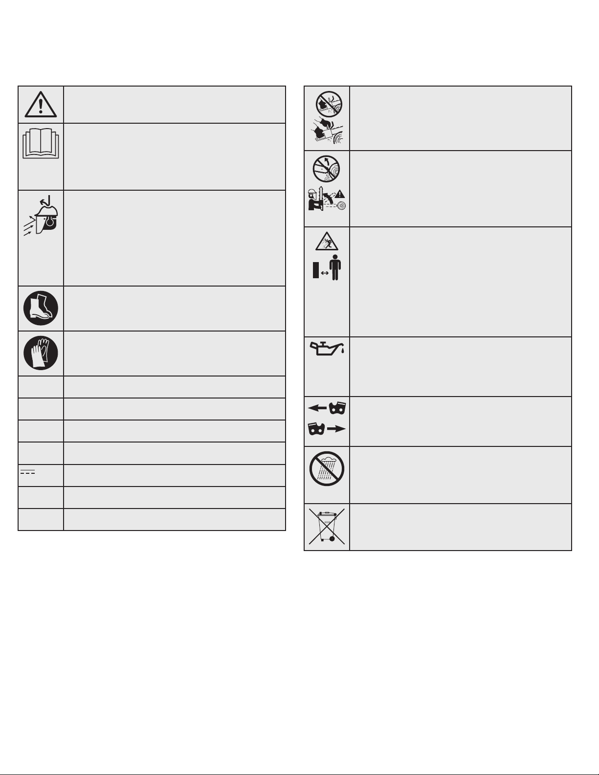
• SAFETY & INTERNATIONAL SYMBOLS •
or DC
This operator's manual describes safety and international symbols and pictographs that may appear on this product. Read the operator's
manual for complete safety, assembly, operating and maintenance and repair information.
SYMBOL MEANING SYMBOL MEANING
• SAFETY ALERT SYMBOL
Indicates danger, warning or caution. May be used in
conjunction with other symbols or pictographs.
• READ OPERATOR'S MANUAL
• USE BOTH HANDS
WARNING:Always use both hands
while operating the unit. Never use only one hand to
operate the unit.
V
A
Hz
AC
WARNING:Read the operator’s
manual(s) and follow all warnings and safety
instructions. Failure to do so can result in serious
injury to the operator and/or bystanders.
• WEAR HEAD, EYE AND HEARING PROTECTION
WARNING:
noise can cause severe eye injury and hearing loss.
Wear eye protection meeting current ANSI / ISEA
Z87.1 standards and ear protection when operating
this unit. Wear head protection when operating this
unit; falling objects can cause severe head injury. Use
a full face shield when needed.
• WEAR FOOT PROTECTION
Always wear heavy-duty, non-slip footwear when
operating this unit.
• WEAR HAND PROTECTION
Always wear heavy-duty, non-slip gloves when
handling this unit.
• VOLTS - Voltage
• AMPERES - Current
• HERTZ - Frequency (cycles per second)
• ALTERNATING CURRENT - Type of current
Thrown objects and loud
• KICKBACK
WARNING:
with any object should be avoided. Tip contact may
cause the guide bar to move suddenly upward and
backward, which may cause serious injury.
• KEEP BYSTANDERS AWAY
Contact of the guide bar tip
WARNING:Keep all bystanders,
especially children and pets, at least 50 feet (15 m) from
the operating area.
WARNING:Always keep a clear work
area and retreat path. Be aware of the location of
limbs/branches to avoid falling limbs and debris.
• CHAIN OIL
Make sure the chain oil reservoir is full before
operation. Check the oil level constantly so that it
does not drop below half full. The saw chain must be
continuously coated with oil to function properly.
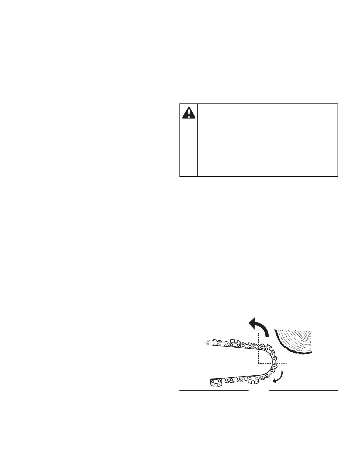
• CHAIN DIRECTION
Make sure the saw chain faces the direction shown
when installed on the guide bar. Refer to Installing the
Guide Bar and Saw Chain in the Maintenance section.
• DO NOT USE IN THE RAIN
Ah
Wh
• DIRECT CURRENT - Type of current
• AMPERE-HOUR - Measure of charge capacity
• WATT-HOUR - Measure of energy
WARNING:
environments. Never operate the unit in the rain or in
damp or wet conditions. Moisture is a shock hazard.
• DO NOT DISPOSE IN HOUSEHOLD TRASH
Recycle the battery or dispose of the battery
according to local, state and federal regulations.
9
Avoid dangerous
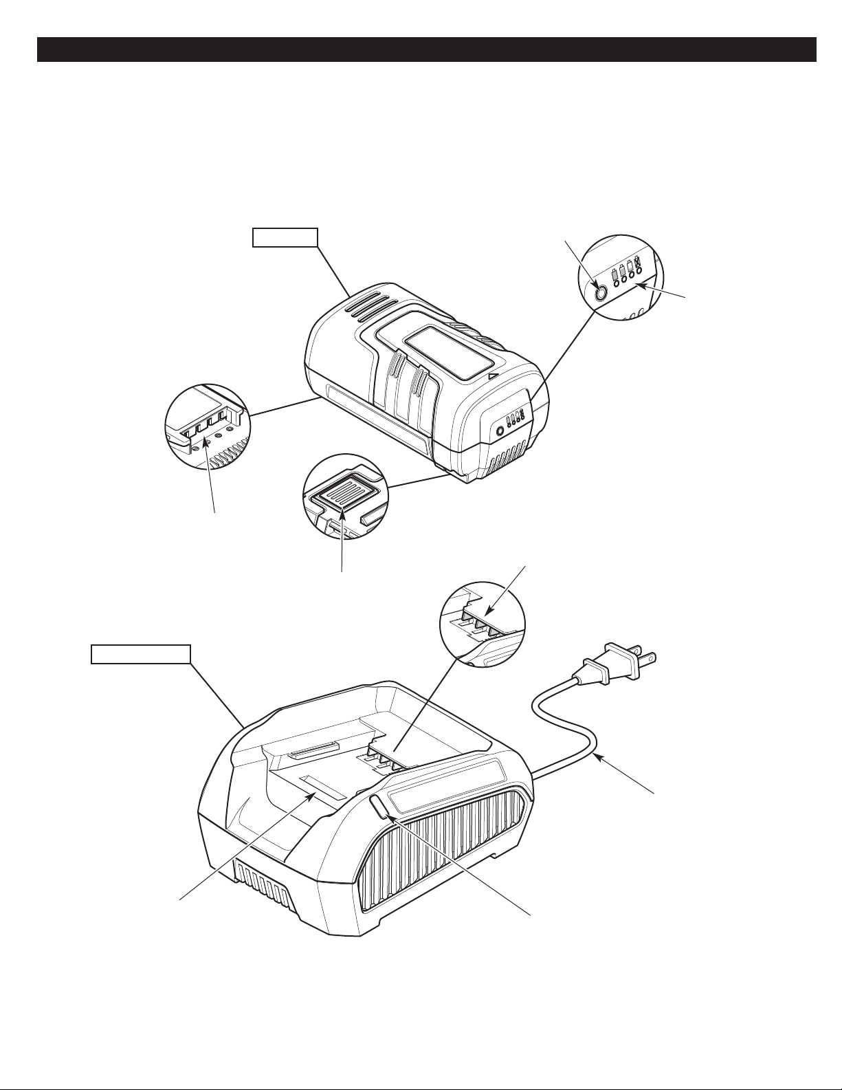
KNOW YOUR UNIT
APPLICATIONS
• Felling and limbing trees
• Cutting logs (bucking)
• Pruning trees
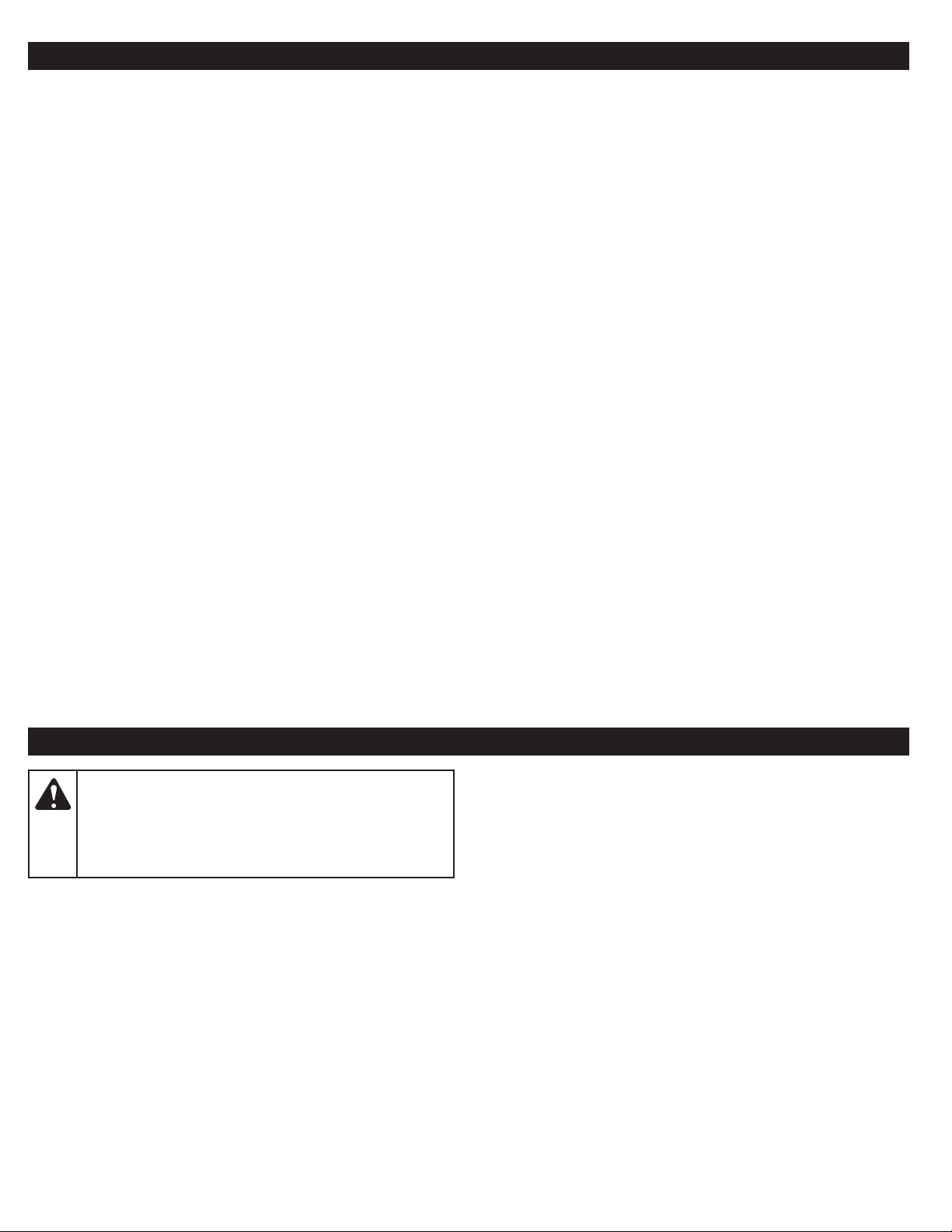
Battery*
NO ASSEMBLY TOOLS REQUIRED
Charge Meter Button
Charge Meter
Lights
Battery Charger*
Charging Dock
Terminals
Terminals
Battery Release
Button
Power Cord
LED
* The battery and battery charger are not included with model RM4040B.
10
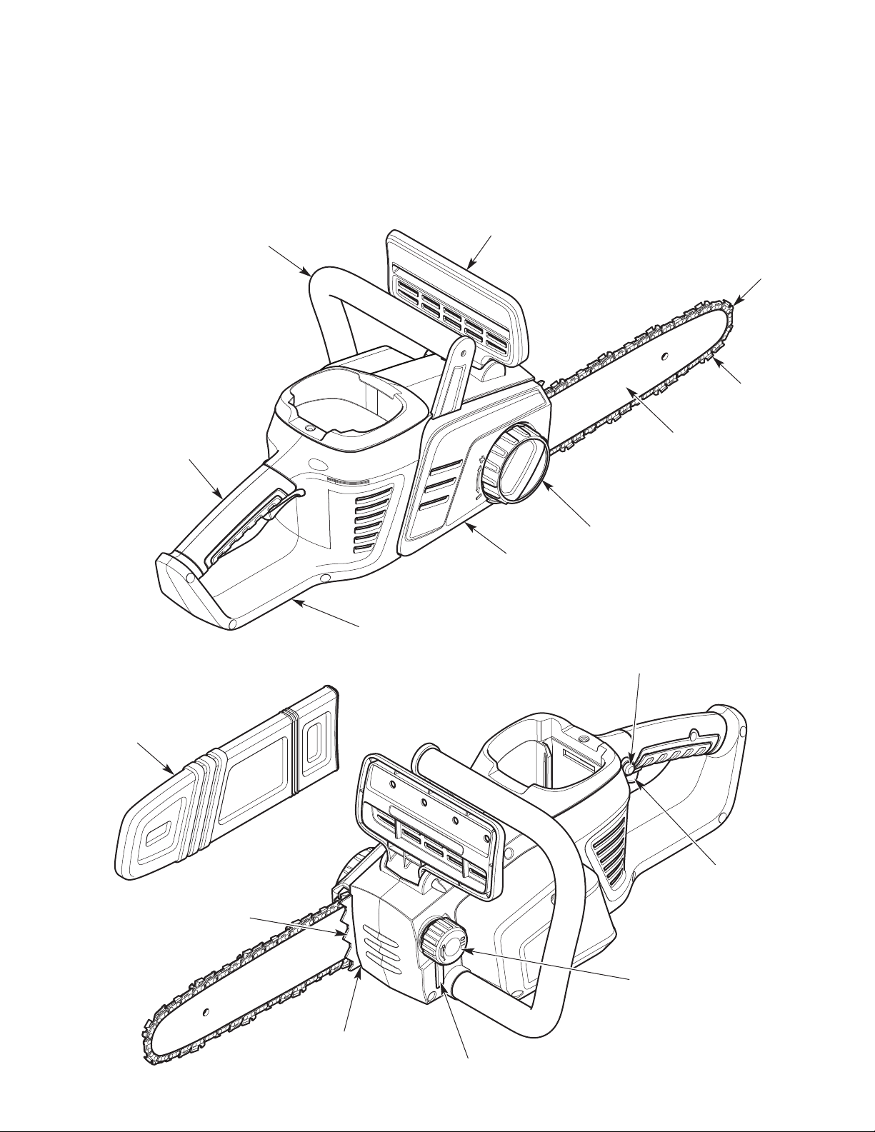
Rear Handle
Front Handle
Chain Brake Lever /
Front Hand Guard
Guide Bar Tip
Saw Chain
Guide Bar
Bar Knob / Chain-Tensioning Ring
Bar Cover
Rear Hand Guard
Scabbard
Trigger Lockout
Trigger
Spiked Bumper /
Bucking Spike
Chain Oil Cap
Chain Catcher
Chain Oil Level Window
11

ESSENTIAL TERMS AND DEFINITIONS
• CHAIN SAW - A tool designed to cut wood with a saw chain. A chain saw is an integrated unit comprised of a motor, saw chain, guide
bar, and handles that are designed to be held by two hands during operation.
• CHAIN SAW POWERHEAD - A chain saw without the saw chain and guide bar.
• DRIVE SPROCKET - A toothed wheel that drives the saw chain.
• FRONT HANDLE - A support handle located toward the front of the chain saw.
• R
EAR HANDLE - A support handle located toward the rear of the chain saw.
• FRONT HAND GUARD / CHAIN BRAKE LEVER - A structural barrier between the front handle and the guide bar. The front hand guard
helps protect the operator’s left hand if it slips off the front handle while the unit is running. The front hand guard is also used to activate
the chain brake.
• CHAIN BRAKE - A device use
The chain brake can be activated intentionally by pushing the front hand guard / chain brake lever forward. It can also be activated if the
operator’s hand strikes the front hand guard / chain brake lever during kickback.
• REAR HAND GUARD - A structural barrier below the rear handle. The rear hand guard
chain breaks or disengages from the guide bar during operation.
• GUIDE BAR - A solid railed structure that supports and guides the saw chain.
• GUIDE BAR TIP - The tip or end of the guide bar.
• REDUCED-KICKBACK GUIDE BAR - A guide bar that has been demonstrated to reduce kickback significantly.
• SAW CHAIN - A loop of chain with teeth designed t
chain is composed of drive links, cutters and side links, held together by rivets.
• LOW-KICKBACK SAW CHAIN - A saw chain that complies with the kickback performance requirements of ANSI/OPEI B175.1-2012 when
tested on a representative sample of chain saws. Low-kickback saw chain significantly reduces the chance of kickback and the intensity
o
f kickback, due to specially designed depth gauges and guard links.
• REPLACEMENT SAW CHAIN - A saw chain that complies with the kickback performance requirements of ANSI/OPEI B175.1-2012 when
tested with specific chain saws. It may not meet the ANSI/OPEI performance standards when used with other chain saws.
• SPIKED BUMPER - The pointed tooth (or teeth), at the front of the chain saw,
maintain a stable position while cutting.
• CHAIN CATCHER - A device designed to intercept a whipping chain. The chain catcher reduces the chance of injury if the saw chain
breaks or disengages from the guide bar during operation.
• OILER CONTROL - A system for oiling the saw chain and guide bar.
• SWITCH - A device that, when operated, w
• SWITCH LINKAGE - A mechanism that transfers motion from the trigger to the switch.
• TRIGGER - A device that, when operated in conjunction with the switch lockout (trigger lockout), turns the motor on. Releasing the trigger
immediately turns the motor off. The saw chain will then coast to a stop.
• SWITCH LOCKOUT (TRIGGER LOCKOUT) - A device that pre
unless the switch lockout (trigger lockout) is manually engaged.
• BATTERY RELEASE BUTTON - A device used to disconnect the battery from the battery charger and the unit.
• KICKBACK - A sudden backward and/or upward motion of the guide bar and saw chain. Kickback can occur if the upper portion of the
guide bar tip touches an object while the saw chain is spinning (ro
pinches the saw chain inside the cut (linear kickback).
• ROTATIONAL KICKBACK - A sudden backward and upward motion of the guide bar and saw chain. Rotational kickback can occur if the
upper portion of the guide bar tip touches an object while the saw chain is spinning. The guide bar and saw chain are
back toward the operator in a lightning-fast reverse reaction.
• LINEAR KICKBACK (PINCH KICKBACK) - A sudden backward motion of the guide bar and saw chain. Linear (pinch) kickback can occur
if the wood closes in and pinches the saw chain inside a cut. The saw is then sent straight back toward the operator.
• NORMAL CUTTING POSITION - The positions assumed while making bucking and felling cuts.
• F
ELLING - The process of cutting down a tree.
• NOTCHED UNDERCUT - The first cutting procedure in the tree felling process. A notch is cut on one side of the tree to direct its fall.
• FELLING BACK CUT - The final cut in the tree felling process. The felling back cut is made on the opposite side of the tree from the
notched undercut.
• BUCKING - The process of cutting a fe
• LIMBING - The process of removing branches from a fallen tree.
• PRUNING - The process of cutting limbs from a living tree.
d to stop the chain saw.
ill complete or interrupt an electrical power circ
e or log into lengths.
lled tre
The chain brake helps protect the user by stopping the saw chain in milliseconds.
helps protect the operator’s right hand if the saw
o cut wood, which is driven by the motor and is supported by the guide bar.
used during felling and bucking to help pivot the saw and
uit to the motor.
vents the unit from starting accidentally. The trigger cannot be squeezed
tational kickback). Kickback can also occur if the wood closes in and
then kicked up and
The saw
12
SPECIFICATIONS*
Approximate Unit Weight (without the battery - without chain oil) . . . . . . . . . . . . . . . . . . . . . . . . . . . . . . . . . . . . . . . .
Lubrication . . . . . . . . . . . . . . . . . . . . . . . . . . . . . . . . . . . . . . . . . . . . . . . . . . . . . . . . . . . . . . . . . . . . . . . . . . . . . . Bar and Chain Oil (not included)
Chain Oil Reservoir Capacity . . . . . . . . . . . . . . . . . . . . . . . . . . . . . . . . . . . . . . . . . . . . . . . . . . . . . . . . . . . . . . . . . . . . . . . . . . . 6.4 fl. oz. (190 mL)
Guide Bar Length . . . . . . . . . . . . . . . . . . . . . . . . . . . . . . . . . . . . . . . . . . . . . . . . . . . . . . . . . . . . . . . . . . . . . . . . . . . . . . . . . . . . . . 12 in. (30.5 cm)
Saw Chain Pitch . . . . . . . . . . . . . . . . . . . . . . . . . . . . . . . . . . . . . . . . . . . . . . . . . . . . . . . . . . . . . . . . . . . . . . . . . . . . . . . . . . . . . . . 3/8 in. (9.5 mm)
Saw Chain Gauge . . . . . . . . . . . . . . . . . . . . . . . . . . . . . . . . . . . . . . . . . . . . . . . . . . . . . . . . . . . . . . . . . . . . . . . . . . . . . . . . . . . . 0.050 in. (1.3 mm)
Battery Type (Model RM4140) . . . . . . . . . . . . . . . . . . . . . . . . . . . . . . . . . . . . . . . . . . . . . . . . . . . . . . . . . . . . . . . . . . . . . . 40V, 4.0 Ah Lithium-Ion
Battery Type (Model RM4150) . . . . . . . . . . . . . . . . . . . . . . . . . . . . . . . . . . . . . . . . . . . . . . . . . . . . . . . . . . . . . . . . . . . . . . 40V, 5.0 Ah Lithium-Ion
Approximate Battery Weight (Model RM4140) . . . . . . . . . . . . . . . . . . . . . . . . . . . . . . . . . . . . . . . . . . . . . . . . . . . . . . . 2.9 - 3.4 lbs. (1.3 -
pproximate Battery Weight (Model RM4150) . . . . . . . . . . . . . . . . . . . . . . . . . . . . . . . . . . . . . . . . . . . . . . . . . . . . . . . 3.0 - 3.5 lbs. (1.4 - 1.6 kg)
A
Optimum Battery Charging Temperature . . . . . . . . . . . . . . . . . . . . . . . . . . . . . . . . . . . . . . . . . . . . . . . . . . . . . . . . . . . . 32° to 104° F (0° to 40° C)
Optimum Battery Storage Temperature . . . . . . . . . . . . . . . . . . . . . . . . . . . . . . . . . . . . . . . . . . . . . . . . . . . . . . . . . . . . . 64° to 73° F (18° to 23° C)
Optimum Battery In-Use Temperature . . . . . . . . . . . . . . . . . . . . . . . . . . . . . . . . . . . . . . . . . . . . . . . . . . . . . . . . . . . . . . 32° to 113° F (0° to 45° C)
Battery Charger Input . . . . . . . . . . . . . . . . . . . . . . . . . . . . . . . . . . . . . . . . . . . . . . . . . . . . . . . . . . . . . . . . . . . . . . . . . . . . . . . 120 V 60 Hz AC only
Battery Charger Output . . . . . . . . . . . . . . . . . . . . . . . . . . . . . . . . . . . . . . . . . . . . . . . . . . . . . . . . . . . . . . . . . . . . . . . . . . . . . . . . . . 1.8 A 40 V DC
Approximate Charging Time (Model RM4140). . . . . . . . . . . . . . . . . . . . . . . . . . . . . . . . . . . . . . . . . . . . . . . . . . . . . . . . . . . . . . . . . . . 135 minutes
App
ximate Charging Time (Model RM4150). . . . . . . . . . . . . . . . . . . . . . . . . . . . . . . . . . . . . . . . . . . . . . . . . . . . . . . . . . . . . . . . . . . 162 minutes
ro
Approximate Battery Charger Weight. . . . . . . . . . . . . . . . . . . . . . . . . . . . . . . . . . . . . . . . . . . . . . . . . . . . . . . . . . . . . 1.25 - 1.75 lbs. (0.6 - 0.8 kg)
* All specifications are based on the latest product information available at the time of printing. We reserve the right to make changes at any
time without notice.
9.5 - 10.5 lbs. (4.3 - 4.8 kg)
1.5 kg)
REPLACEMENT PARTS
Please contact the Customer Support Department to order replacement parts.
Part #
713-05074 . . . . . . . . . . . . . . . . . . . . . . . . . . . . . . . . . . . . . . . . . . . . . . . .
795-00321 . . . . . . . . . . . . . . . . . . . . . . . . . . . . . . . . . . . . . . . . . . . . . . . .
ASSEMBLY
WARNING:
damage to the unit, never assemble, disassemble or adjust
the unit while it is running. Always turn the unit off and
remove the battery to prevent the unit from starting
accidentally. Always allow the unit to cool before
assembling, disassembling or making any adjustments.
ADDING BAR AND CHAIN OIL: INITIAL USE
This unit comes from the factory with the chain oil reservoir empty.
Fill the chain oil reservoir with bar and chain oil before starting or
using the unit. Refer to Adding Bar and Chain Oil instructions in the
Maintenance section.
To prevent serious personal injury and
Description
Saw Chain (12 in. / 30.5 cm)
Guide Bar (12 in. / 30.5 cm)
ADJUSTING THE CHAIN TENSION: INITIAL USE
The saw chain must be properly tensioned before attempting to
start or operate the unit. The saw chain may also re
tensioning as the saw chain heats up during operation. Refer to
Adjusting the Chain Tension instructions in the Maintenance section.
quire additional
13
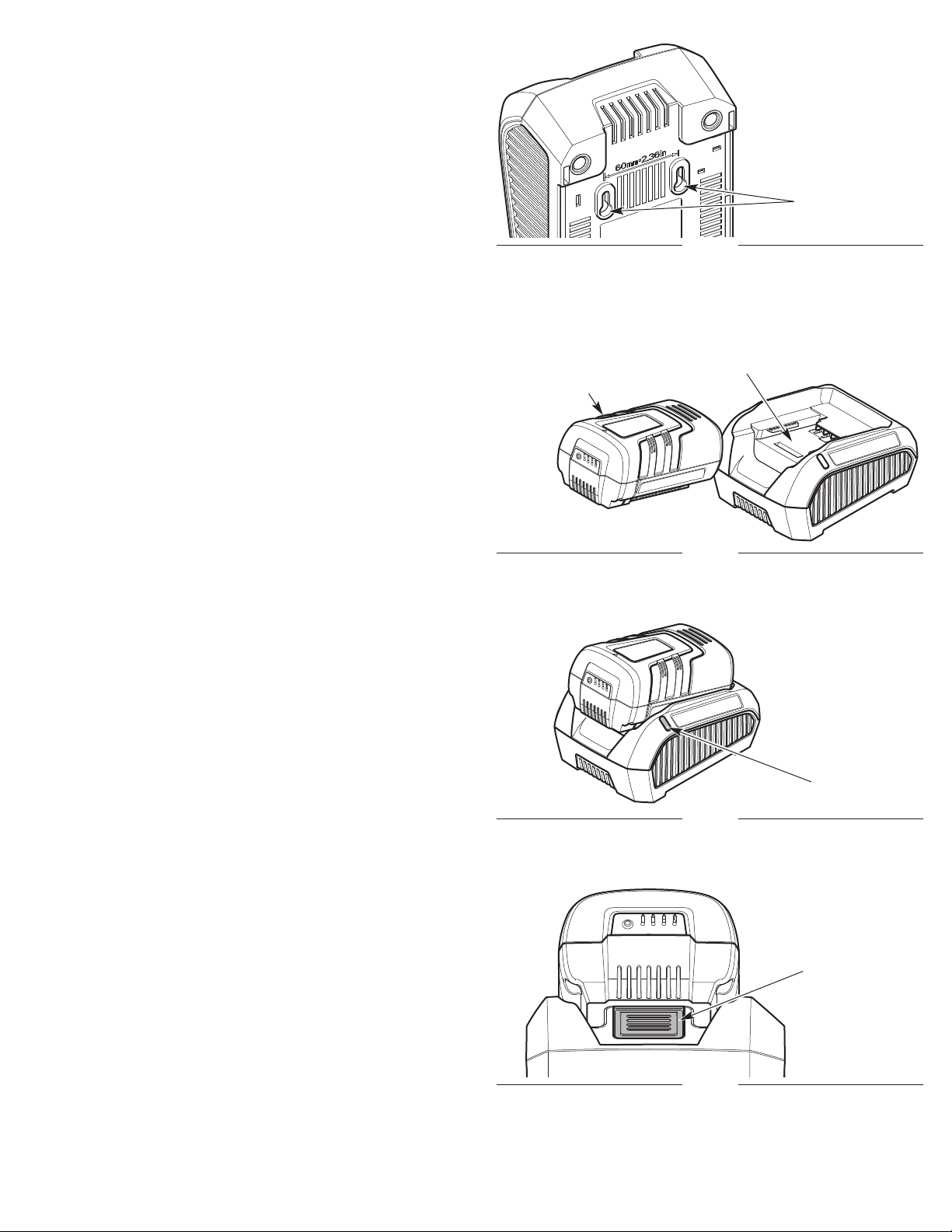
WALL-MOUNTING THE CHARGER (OPTIONAL)
The battery charger can be mounted to a permanent surface, such
as a wall or work bench. Use mounting fasteners (not included)
capable of supporting the combined weight of the battery and
battery charger. Wall-mounting holes are located on the bottom of
the charger (Fig. 10).
Wall-Mounting
Holes
Fig. 10
CHARGING THE BATTERY
NOTE: The battery is not shipped fully charged.
NOTE: Lithium-ion batteries will not develop a memory and may be
charged at any time.
For maximum run time, fully charge the battery before each use.
1. Plug the battery charger into an appropriate power outlet. The
LED should turn red (constant) (Fig. 12). If it does not:
• Make sure the battery charger is fully plugged into an
appropriate
ake sure the power outlet is functioning by testing it with
• M
another electrical device.
2. Insert the battery into the charging dock (Fig. 11). Push the
battery firmly until it locks into place.
3. Examine the LED. The LED will indicate the battery status:
• Green (blinking): The battery is charging. Charge the battery
until the green light stops blinking.
• Green (constant): The battery is fully
• Red (blinking - slow): The battery and/or charger are too hot
or too cold. Make sure the battery and charger are in an
environment between 32° and 104° F (0° and 40° C). Allow
time for the battery and/or charger to warm up or cool down.
• Red (blinking - fast): The battery is no longer functional. Refer
to the Warranty section for replacement information.
• Red (constant): The battery is not chargin
attery. Make sure the terminals on the battery and battery
b
charger are clean. Re-insert the battery into the charging dock.
Push the battery firmly until it locks into place.
4. To maximize the life of the battery, the battery charger will turn
off when charging is complete. Once the battery is fully charged,
remove it from the battery charger. Optionally, the battery can be
stored in the
unplugged from the power outlet.
To remove the battery: Hold the battery charger in place with
one hand. Press the battery release button with the other hand
(Fig. 13). Slide the battery out of the charging dock.
power outlet.
battery charg
ed.
charg
g. Remove the
er, but the battery charger should be
Charging Dock
Battery
Fig. 11
LED
Fig. 12
Battery Release
Button
14
Fig. 13
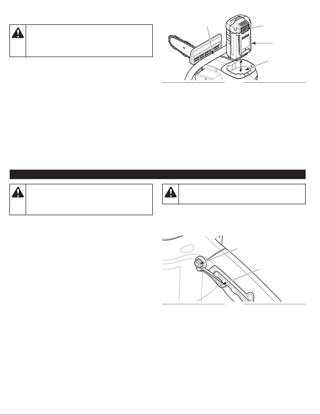
INSTALLING AND REMOVING THE BATTERY
WARNING:
prevent serious injury, DO NOT press the trigger lockout
and DO NOT squeeze the trigger when installing or
removing the battery. Refer to Starting and Stopping.
Remove the battery from the unit when it is not in use.
Avoid accidentally starting the unit. To
Front Handle
Battery
Release Button
Battery
Installing the Battery
1. Grasp the front handle firmly (Fig. 14).
2. Slide the battery into the battery port (Fig. 14). Push the battery
firmly until the battery locks into place (Fig. 14). There should be
an audible “click.”
3. Gently pull the battery to make sure it is securely locked in place.
Removing the Battery
1. Grasp the front handle firmly (Fig. 14).
2. Press the
3. Pull the battery out of the battery port (Fig. 14).
NOTE: It may require a strong pull to remove the battery.
battery re
lease button to unlock the battery (Fig. 14).
STARTING AND STOPPING
WARNING:
and saw chain properly installed. Make sure the guide bar
cover is securely assembled. Make sure the saw chain is
properly tensioned. Refer to Adjusting the Chain Tension
instructions in the Maintenance section.
Never operate the unit without the guide bar
Battery Port
Fig. 14
WARNING:
Keep hands and feet clear of the saw chain and do not
allow the saw chain to contact any object(s).
The saw chain will spin after the unit starts.
BEFORE STARTING THE UNIT
1. Fill the chain oil reservoir with bar and chain oil. Refer to Adding
Bar and Chain Oil in the Maintenance section.
2. Install the battery. Refer to Installing the Battery.
STARTING INSTRUCTIONS
NOTE: To help prevent the motor from starting accidentally, this unit
has a trigger lockout. The trigger lockout and trigger must both
be engaged to start the unit.
1. Press and hold the trigger lockout (Fig. 15).
2
. Continue to hold the trigger lockout. Squeeze and hold the
trigger to start the unit (Fig. 15).
3. Release the trigger lockout, but continue to squeeze the trigger
to the degree needed for the operation.
STOPPING INSTRUCTIONS
1. Release the trigger (Fig. 15).
2. Wait for all moving parts to come to a complete stop.
NOTE: Upon release of the trigger, the trigger lockout will reset to
the locked position.
Trigger Lockout
Trigger
Fig. 15
15
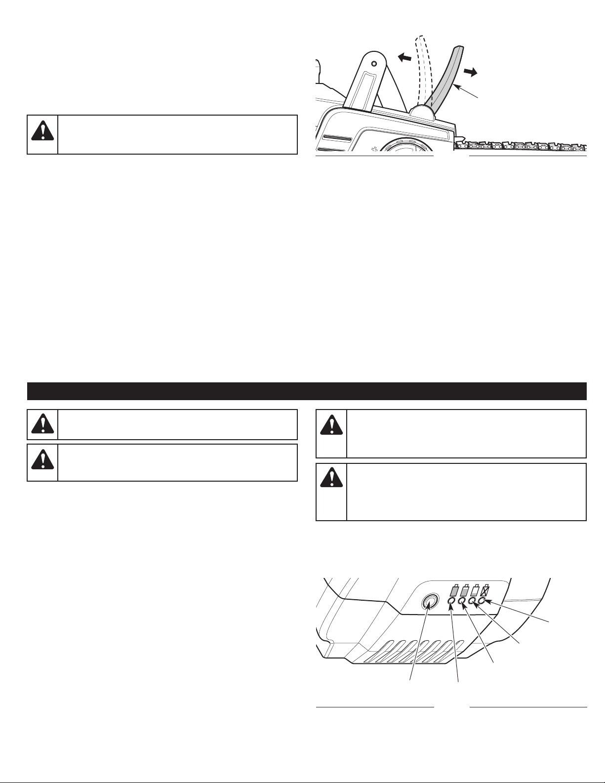
USING THE CHAIN BRAKE
In emergency situations, the saw chain can also be stopped by
engaging the chain brake. The chain brake can be activated
intentionally by pushing the front hand guard / chain brake lever
forward. It can also be activated if the operator’s hand strikes the
front hand guard / chain brake lever during kickback.
Testing the Chain Brake
WARNING:
deliberately. Keep the saw chain from touching anything.
Do not let the chain saw tip forward.
Always test the chain brake before using the unit.
1. S
et the unit on a flat, level surface.
2. Make sure the front hand guard / chain brake lever is pulled
back in the disengaged position (Fig. 16).
3. Grip the unit firmly with both hands. Refer to Holding the Unit in
the Operation section.
4. Start the unit. Refer to Starting Instructions.
5. While the unit is running, engage the chain brake by pushing the
front hand guard / chain brake lever forward with the
Fig. 16). The chain should stop moving abruptly. If it does not,
(
have the unit serviced by an authorized service center.
6. Stop the unit. Refer to Stopping Instructions.
7. Pull the front hand guard / chain brake lever back to the
disengaged position.
Always activate the chain brake slowly and
left hand
Disengaged
Engaged
Chain Brake Lever /
Front Hand Guard
Fig. 16
OPERATION
WARNING:
conditions.
WARNING:
necessary before beginning operation. Refer to Adjusting the
Chain Tension in the Maintenance section.
CHECKING THE BATTERY CHARGE LEVEL
1. Press the charge meter button (Fig. 17).
2. One or more of the charge meter lights should illuminate (Fig. 17).
The number and color of the lights will indicate the current
battery charge level:
• 3 Green Lights = 66 - 100% Charge
• 2 Green Lights = 33 - 66% Charge
• 1 Green Light = 1 - 33% Charge
• 1 Red Light = 0% Charge
3. If the red light illuminates, charge the battery
OTE: While in use, lithium-ion batteries provide power with
N
minimal power fade. When the battery is fully discharged, it will
immediately cut power to the unit and require charging.
Do not expose power tools to rain or wet
Always check the chain tension and adjust as
before any further use.
WARNING:
before operation. Check the oil level constantly so that it
does not drop below half full. The saw chain must be
continuously coated with oil to function properly.
WARNING:
foot and body protection to reduce the risk of injury when
operating this unit. Wear head protection. Use a full face
shield when needed. Refer to the Safety section for
appropriate safety equipment information.
Charge Meter Button
Make sure the chain oil reservoir is full
Always wear appropriate eye, hearing, hand,
1% - 33%
33% - 66%
66% - 100%
Fig. 17
0%
16
TIPS FOR BEST RESULTS
• Follow all safety instructions. Refer to the Safety section.
• Only cut wood and materials made of wood. Do not attempt to cut
sheet metal, plastics, masonry or any other non-wood materials.
• Work slowly and maintain careful control.
• Practice cutting a few small logs before beginning a major
cutting operation. First-time users should practice cutting logs
on a sawhorse or cradle b
• Do not attempt to cut trees or logs with diameters larger than 10
in. (25.4 cm).
• When pruning, remove lower branches first to allow clear access
to higher branches and to provide space for falling branches.
• When pruning, remove long branches in stages, not all at once.
undertaking other operations.
efore
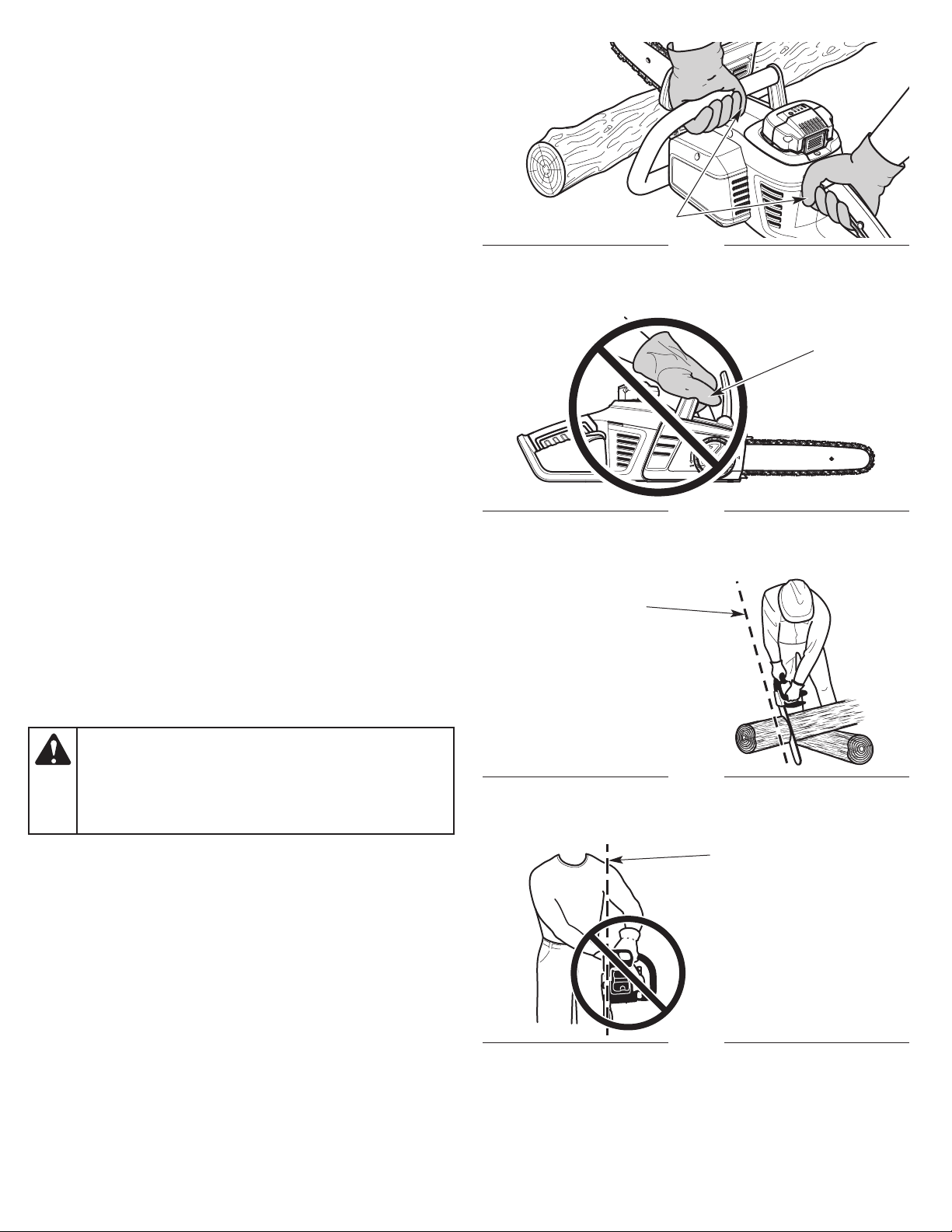
Correct Grip
Thumbs Below the Handles
Fig. 18
PREPARING THE WORK AREA
• Clear the area of children, bystanders and pets; keep them
outside a 50-foot (15 m) radius, at a minimum. Even then, they
a
re still at risk from thrown objects. Encourage bystanders to
wear eye protection. If you are approached, stop the unit
immediately. When felling, the safe distance is at least twice the
height of the tallest tree in the work area. When bucking, keep
workers at least 15 feet (4.6 m) apart.
• Keep the work area clean. Cluttered areas invite injuries. Do not
start cutting until the work are
a is clear and free from
obstructions. Make sure there is secure footing and a planned
retreat path from falling trees or branches.
• Do not cut near electrical cables or power lines. Keep at least 50
feet (15 m) away from all power lines.
• Use the unit only in daylight or good artificial light.
HOLDING THE UNIT
WARNING:
below whether the operator is left-handed or right-handed.
This will help keep the operator slightly to the left of the
unit and out of the direct line of the saw chain if kickback
occurs (Fig. 20 and Fig. 21). Always keep all body parts to
the left of the chain line.
Always use the hand placements specified
Incorrect Grip
Correct Stance
Thumb
Above the
Handle
Fig. 19
Chain Line
Fig. 20
• Always grip the unit firmly with both hands when the unit is
running.
• F
irmly encircle the handles with the thumbs and fingers (Fig. 18).
This will help reduce the chance of losing control of the unit if
kickback occurs. Any grip with thumbs and fingers on the same
side of the handles is dangerous (Fig. 19).
• Stand in a stable position with feet apart and firmly planted.
• Hold the front handle with the left hand. Keep the left arm
straight to help withstand potent
old the rear handle with the right hand. Keep the right arm
• H
ial kickback.
slightly bent.
• Do not cut above shoulder height. Do not overreach.
• When carrying the chain saw from one place to another, hold it
by the front handle, away from the body, and keep the guide bar
pointed to the rear.
Chain Line
Incorrect Stance
Fig. 21
17
CUTTING PROCEDURE BASICS
90°
1. Start the unit. Refer to Starting Instructions in the Starting and
Stopping section.
2. Make sure that oil is flowing onto the guide bar and saw chain. A
small spray should be visible. When using the unit for the first
time, allow 30-60 seconds for the oil to begin flowing.
3. Press the unit against the wood and maintain a firm, steady
pressure through most of the cut. Do not put
unit at the end of the cut.
4. Keep the unit running through the entire cut.
5. Do not try to force the saw through the wood. Allow the saw
chain to do the cutting. Exert only light pressure. Forcing the cut
could result in damage to the unit or personal injury.
6. Release the trigger as soon as the cut is completed. Allow the
saw chain to come to a complete stop. The saw chain, guide bar
a
nd motor may experience unnecessary wear if the unit is run
ithout a cutting load.
w
ssure on the
pre
FELLING: SAFETY
Felling is the process of cutting down a tree. Follow these safety
precautions to reduce the risk of serious injury, property damage
and damage to electrical lines:
• Do not fell trees with an extreme lean. Do not fell trees with
rotten limbs, loose bark or hollow trunks. Have these trees
pushed or dragged do
o not cut trees near buildings or electrical lines. Leave these
• D
operations for professionals. If a felled tree does contact an
electrical line, notify the utility company immediately.
• Check the tree for damaged or dead branches that could fall
and cause serious injury.
• Remove dirt, stones, loose bark, nails, wire and other
obstructions from the portion of the tree that will b
hen bucking and felling operations are performed by two or
• W
more persons in the same general area, they should be
separated from each other by a distance of at least twice the
height of the tree to be felled.
• Consider the force and direction of the wind. Consider the lean
and balance of the tree. Consider the location of large branches.
All of these factors influence the direction that the tree
not try to fell a tree in a direction other than its natural fall line.
o not fell trees during periods of precipitation or high winds.
• D
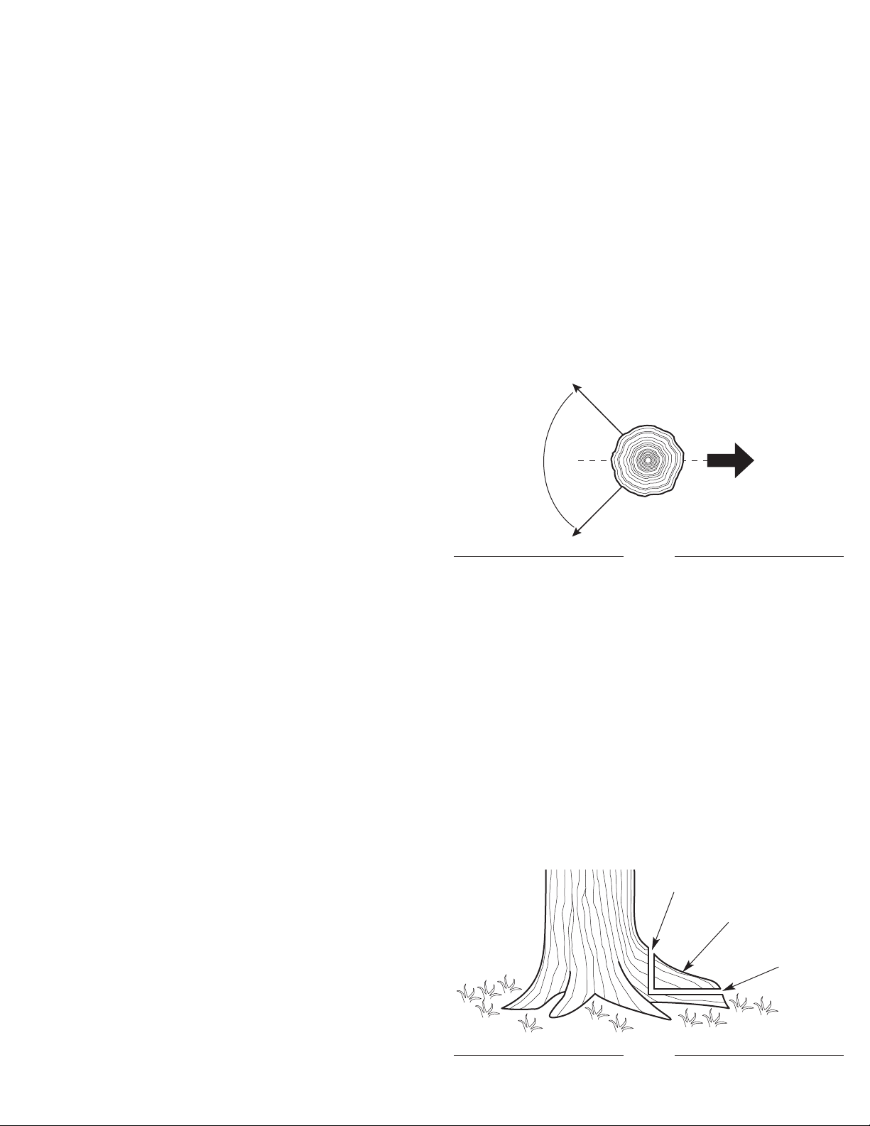
• Determine a safe and expedient escape route. Clear the area
around the tree and make sure there are no obstructions
blocking the escape route. Establish a 90º corridor of escape,
approximately 135º from the line of fall (Fig. 22).
• Stay uphill from the t
wn with heavy equipment.
e cut.
will fall. Do
ree; it will most likely roll or slide after it falls.
Path of Safe
Retreat
135º From Planned
Line of Fall
Planned
Line of Fall
135º From Planned
Line of Fall
Fig. 22
FELLING: PROCEDURE
Small trees, up to 6 - 7 inches (15 - 18 cm) in diameter, are usually
felled in a single cut. Larger trees require a sequence of two cutting
operations: a notched undercut followed by a felling back cut. It
may also be necessary to remove buttress roots.
Step 1: Removing Buttress Roots
Buttress roots are large roots that extend above the ground and
help support the tree. If the tree has
impede the felling process, follow these steps to remove them:
e buttress roots that might
larg
Second Cut
Buttress Root
First Cut
Fig. 23
18
1. Make a horizonal cut into the buttress root (Fig. 23). To prevent
the guide bar from being pinched by the weight of the wood,
always make this cut first.
2. Make a vertical cut into the buttress root (Fig. 23).
3. Remove the loose section from the work area.
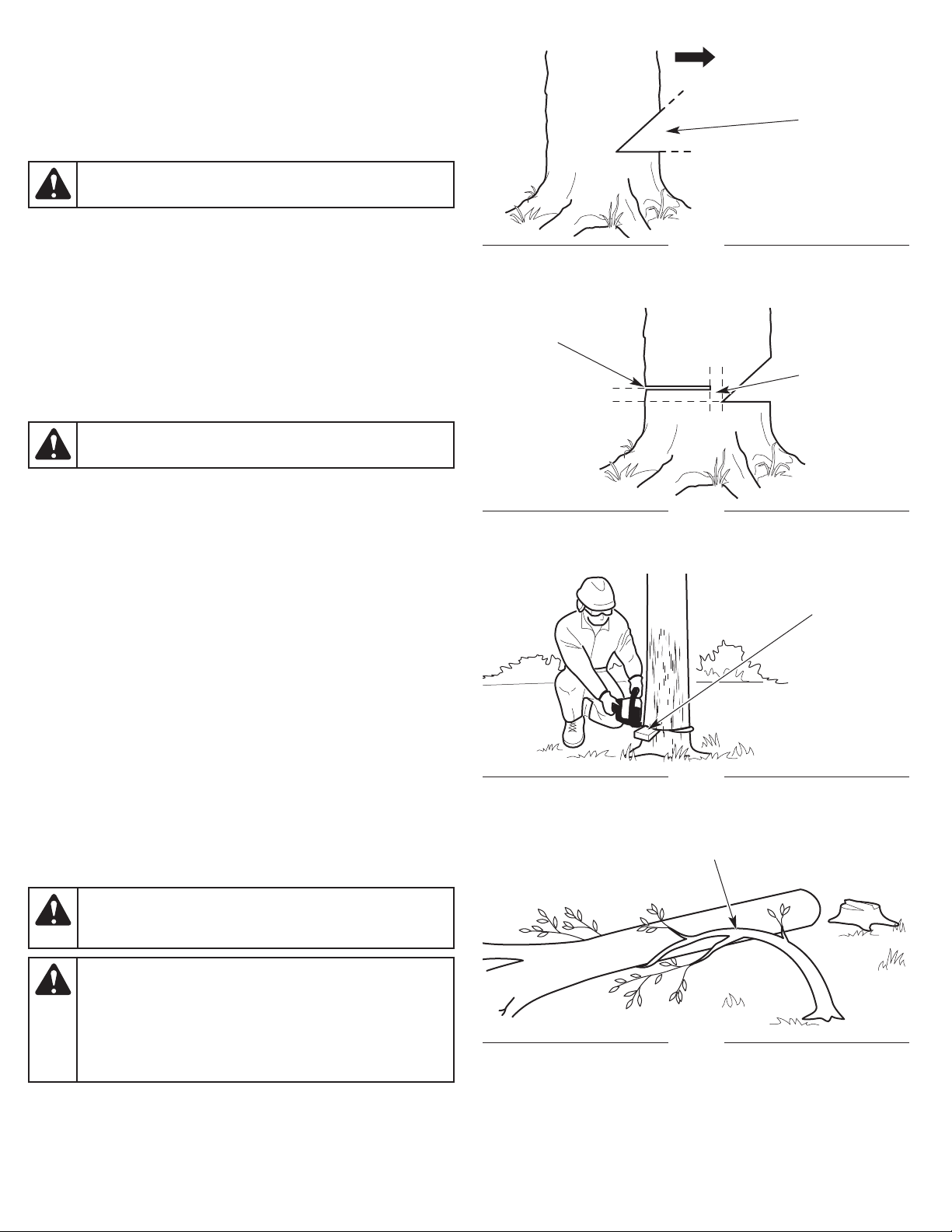
Step 2: Making the Notched Undercut
WARNING:
Never walk in front of a tree with a notched
undercut.
This cut determines which direction the tree will fall. Always make
this cut on the side of the tree facing the dire
ction where the tree
should fall. Make the cut at 90º to the line of fall.
1. Make a horizontal cut into the trunk of the tree (Fig. 24). The cut
should be about 1/3 the diameter of the tree and close to the
ground. To prevent the guide bar from being pinched by the
weight of the wood, always make this cut first.
2. Make a 45º cut into the trunk of the tree, above the first cut (Fig.
24). Continue cutt
. Remove the loose section from the work area.
3
ing until the two cuts meet.
Step 3: Making the Felling Back Cut
Felling
Back Cut
1/3 Diameter
2 inches
(5 cm)
45º
Direction of Fall
Second Cut
Notched
Undercut
First Cut
Fig. 24
2 inches
(5 cm)
Hinge
WARNING:
Always recheck the area for bystanders,
animals and obstacles before making the felling back cut.
This cut fells the tree.
1. Make a horizontal cut into the opposite side of the tree from the
notched undercut (Fig. 25). Make the cut approximately 2 inches
(5 cm) above the bottom of the notched undercut (Fig. 25).
2. As the cut gets close to the notched undercut, only a thin band
of wood will support the tre
e. This band of wood is referred to as
the hinge (Fig. 25). The hinge helps control the fall of the tree.
Leave approximately 2 inches (5 cm) of hinge in place. Do not
cut through the hinge. Cutting through the hinge could cause the
tree to fall in any direction.
3. Periodically glance up during the felling back cut to see if the
tree is going to fall in the correct direction. If there is
hat the tree might not fall in the desired direction, or if the tree
t
a chance
might rock back and bind the chain saw, remove the guide bar
from the cut, stop the unit and use wedges to open the cut and
direct the fall (Fig. 26). Only use soft plastic or wooden wedges.
Drive the wedges into the cut slowly. Once the wedges are in
place and the cut is held open, either carefully reinsert the guide
bar and
p
continue the cut or slowly drive the wedges in further to
ush the tree over.
4. As the hinge gets smaller, the tree should begin to fall. When the
tree begins to fall, remove the chain saw from the cut, stop the
motor and set the unit down immediately. Promptly exit the area
along the retreat path, but keep watching the tree as it falls.
Fig. 25
Wedge
Fig. 26
Spring Pole
DANGER:
If the tree starts to fall in the wrong direction
and binds the chain saw, leave the unit and evacuate the
area immediately! Do not try to save the chain saw!
WARNING:
Stay clear of spring poles when operating the
unit. Spring poles are branches, logs, roots or saplings that
are bent under tension by other wood (Fig. 27). When the
tension is released, spring poles can strike the operator,
causing serious injury and potentially knocking the chain
saw into the operator’s body. Use extreme caution when
cutting spring poles or when releasing the cause of tension.
Fig. 27
19
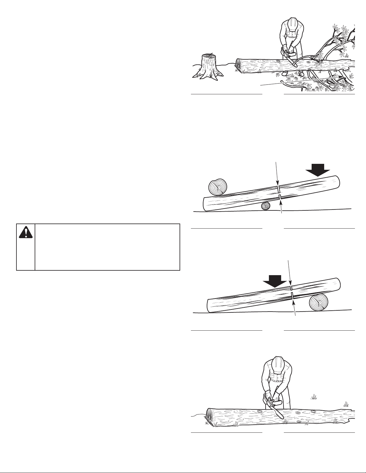
LIMBING
Limbing is the process of removing branches from a fallen tree.
1. Leave the larger support limbs under the tree for last (Fig. 28).
These will keep the tree off the ground during the limbing process.
2. Cut one limb at a time. Stand on the opposite side of the tree
from the limb (Fig. 28). Keep the trunk between the operator and
the chain saw. To avoid binding the chain saw, branches under
tensi
on should be cut fro
m the bottom up.
3. Remove the cut limbs from the work area.
BUCKING: SAFETY
Bucking is the process of cutting a fallen tree into logs of desired
lengths. Follow these safety precautions to reduce the risk of
serious injury:
• Clear the area of objects or obstructions that could contact the
guide bar and result in kickback.
• When bucking on a slope, always stand on the uphill side of the
fallen tree.
• If possible, the end of the tree to be cut should be raised off
he ground. A saw horse is ideal for this purpose. If a saw horse
t
is not available, use other logs or any remaining limb stumps.
Make sure the tree if firmly supported.
• Do not let the saw chain contact the ground or saw horse.
• Cut one log at a time. Release the trigger and allow the saw chain
to come to a complete stop before moving on to the next log.
• Keep feet and all other body parts clear of fa
lling logs.
of
Log Supported
on One End
Support Limb
Fig. 28
Second Cut
First Cut (1/3 Diameter)
Load
DANGER:
Use extreme caution when cutting a fallen
tree that is still attached to the root structure. When the
trunk is separated from the roots, the stump has a high
potential for rocking back into the hole created by the
roots. This can result in serious injury or death. Never
stand in the hole left by the roots. Never allow others to
stand near the root structure.
BUCKING: PROCEDURE
Cutting Logs Under Stress
When logs are supported on one or both ends, the wood tends to
bend during the cutting process. This can cause the chain saw to
become pinched between the two sides. Pay extra attention.
1. Make the first cut approximately 1/3 the diameter of the log. Do
not cut deeper than 1/3.
• If the log is supported on one end (Fig. 29), make the first cut
from below (un
f the log is supported on two ends (Fig. 30), make the first cut
• I
from above (overbucking). Refer to Overbucking.
2. Make the second cut from the opposite side until the two cuts meet.
If the diameter of the wood is large enough, insert soft plastic or
wooden wedges to hold the cut open and prevent pinching (Fig. 33).
Take care not to touch the wedges with the saw ch
derbucking). Refer to Underbucking.
ain.
Log Supported
Two Ends
Overbucking
Fig. 29
First Cut (1/3 Diameter)
Load
Second Cut
Fig. 30
20
Fig. 31
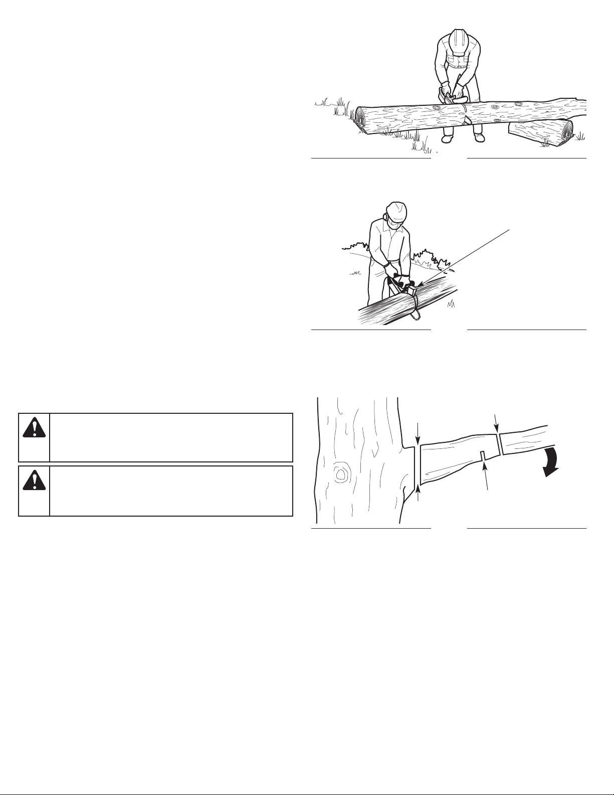
Cutting Fully-Supported Logs
When logs are supported along the entire length, extra care should
be taken to make sure the saw chain does not contact the ground
or other support structure (Fig. 31).
1. Cut through the log as much as possible, without cutting into
the ground or support structure. Cut from above (overbucking).
Refer to Overbucking.
2. Roll the log over and finish cutting th
ugh the log from above
ro
(overbucking).
Overbucking
1. Begin cutting from above, with the bottom of the saw chain
against the top of the log (Fig. 31).
2. Exert light, downward pressure. The saw will tend to pull away
from the operator. Be prepared and hold the saw firmly to
maintain control.
Underbucking
1. Begin cutting from below, with the top of the saw chain against
the bottom of the log (Fig. 32).
2. Exe
rt light, upward pressure. The saw will tend to push toward the
operator. Be prepared and hold the saw firmly to maintain control.
Underbucking
Fig. 32
Wedge
PRUNING
WARNING:
chain saw. Use a pole saw to cut limbs above shoulder
height or hire a professional. Do not operate the unit in a
tree or on a ladder unless specifically trained to do so.
WARNING:
Always wear appropriate head protection. Plan an escape
route away from falling limbs. Do not stand, or position any
body parts, directly below the branch being cut.
Pruning is the process of cutting limbs from a living tree.
1. Make the first cut approximately 6 inches (15 cm) from the tree
trunk. Cut upward, from the underside of the limb. Use the top
of the guide bar to make this cut. Cut a third of the way through
the diameter of the limb (Fig. 34).
2. Make the second cut 2 - 4 inches (5 - 10 cm) farther out on the
limb. Cut downward, from the top of
he guide bar to make this cut. Cut completely through the limb
t
(Fig. 34).
3. Make the third cut as close to the tree trunk as possible. Cut
upward, from the underside of the limb stub. Use the top of the
guide bar to make this cut. Cut a third of the way through the
diameter of the limb (Fig. 34).
4. Make the fourth cut directly above the third cut. Cut downward,
from the top o
ake this cut. Cut completely through the limb stub to meet the
m
third cut (Fig. 34). This will remove the limb stub.
Do not cut above shoulder height with a
Falling branches can cause serious injury.
the limb. Use the bottom of
f the limb stub. Use the bottom of the guide bar to
Fig. 33
Second Cut
Fourth Cut
First Cut
Third Cut
Fig. 34
21
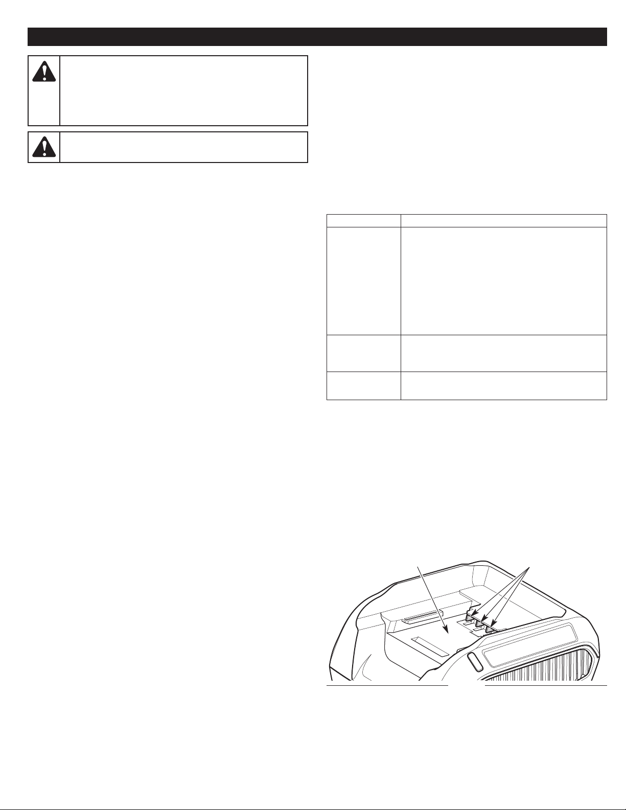
MAINTENANCE
WARNING:
maintenance on the unit while it is running. Always remove
the battery to prevent the unit from starting accidentally.
Always allow the unit to cool before maintaining the unit.
Before maintaining the battery charger, always unplug it
from the power outlet.
WARNING:
safety instructions to prevent serious personal injury.
To prevent serious injury, never perform
Wear protective clothing and observe all
MAINTENANCE SCHEDULE
Perform these required maintenance procedures at the frequency
stated in the table. These procedures should also be a part of any
seasonal tune-up.
All service, other than the maintenance procedures described in
this manual, should be performed by an authorized service center.
NOTE: Some maintenance procedures may require special tools or
skills. If you are unsure about the
an MTD authorized service center.
cedures, take the unit to
se pro
CUSTOMER RESPONSIBILITY
FREQUENCY MAINTENANCE REQUIRED
Before each
use
After each use • Clean the unit and inspect decals. Refer to
Every 10 hours • Clean the guide bar groove and oil
• Check for loose screws, nuts or bolts
(tighten as needed)
• Check for damaged or worn parts*
• Check the saw chain sharpness. Refer to
Sharpening the Saw Chain.
• Check the chain tension (adjust as needed).
Refer to Adjusting the Chain Tension.
• Fill the chain oil reservoir (refill frequently).
Refer to Adding Bar and Chain Oil.
Cleaning in the Cleaning and Storage
section.
passages.
MAINTAINING THE BATTERY CHARGER
• Keep the battery charger clean and clear of debris. Do not allow
foreign material into the charging dock or onto the terminals (Fig.
35). Inspect the battery charger for foreign material before each use.
• Make sure the charger has not been shorted by debris. Inspect
the terminals for soot and signs of melting. Do not attempt to
use a shorted charger.
* If maintenance or replacement is required, have the unit serviced
by an MTD authorized service center.
Charging Dock
Fig. 35
Terminals
22
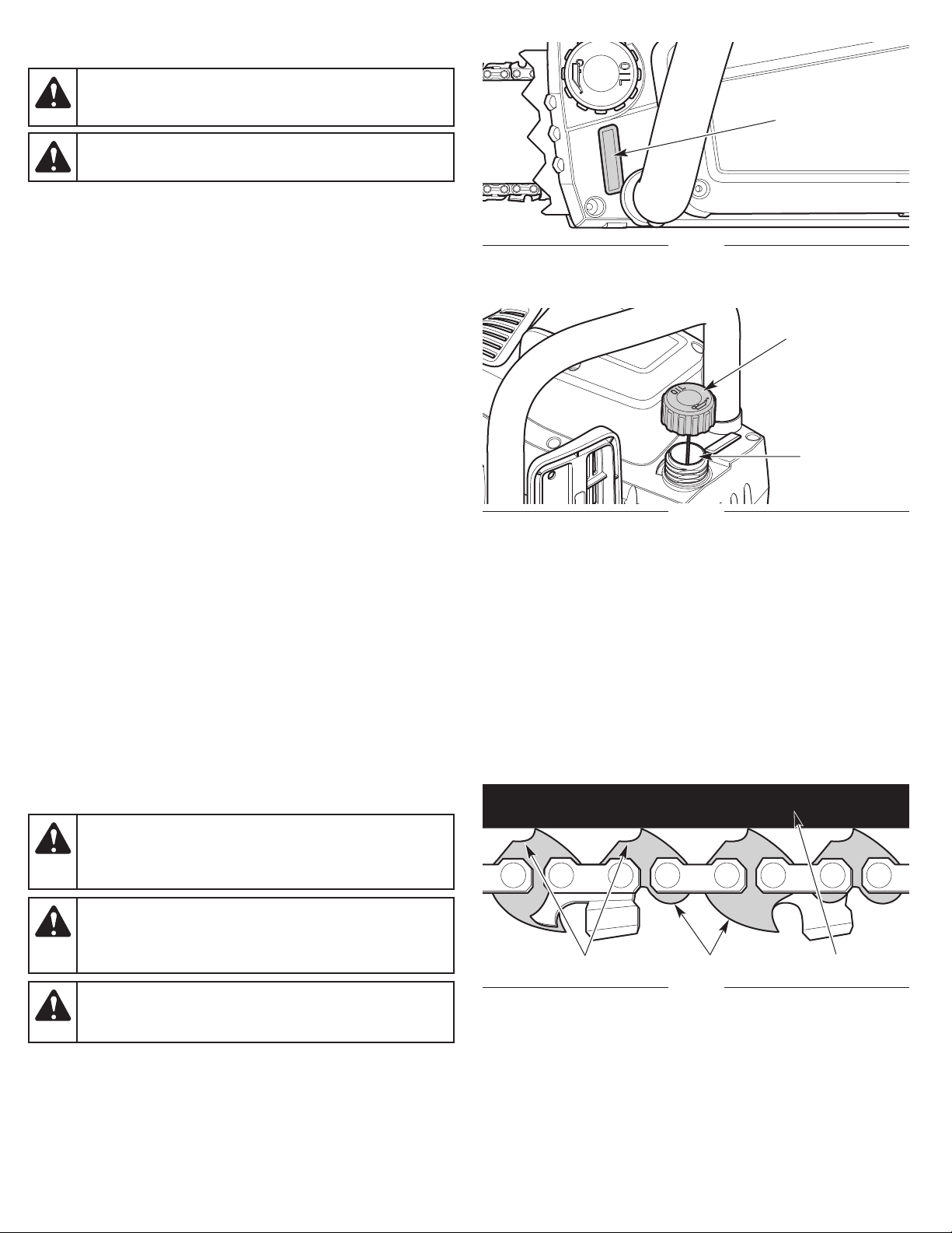
ADDING BAR AND CHAIN OIL
DANGER:
irreparable damage to the unit. Make sure the chain oil
reservoir is always filled. Always use bar and chain oil.
WARNING:
does not drop below half full.
The guide bar and saw chain require lubrication to minimize friction.
Never starve the guide bar and chain of lubricating oil. Running the
unit without enough oil will decrease cutting efficiency, shorten the
life of the saw chain, cause rapid dulling of the saw chain and
excessive wear to the guide bar from overheating. An insufficient
amount of lubricating oil is evidenced b
iscoloration or pitch build-up.
d
Only use bar and chain oil that is formulated to perform over a wide
range of temperatures with no diluting required in the chain oil
reservoir. Do not use motor oil or any other petroleum-based oil. Do
not use dirty, used or contaminated oil. Damage may occur to the
guide bar or saw chain. Dispose of old oil according to federal, state
and local regul
hecking the Chain Oil Level
C
1. Set the unit on a flat, level surface. Position the unit upright
(Fig. 36).
2. Look into the chain oil level window. The oil level should fill the
window at least halfway (Fig. 36). If the oil level is too low, add
bar and chain oil. Refer to Filling the Chain Oil Reservoir.
Filling the Chain Oil Reservoir
1. Set the unit on a flat, level surface. Position the unit wit
hain oil cap facing up (Fig. 37).
c
2. To prevent debris from entering the chain oil reservoir, use a clean
cloth to clean the chain oil cap and surrounding area.
3. Unscrew the chain oil cap (Fig. 37).
4. Carefully pour the oil into the chain oil reservoir. DO NOT overfill.
5. Reinstall the chain oil cap. Tighten the chain oil cap firmly.
6. Wipe up any oil that may have spilled.
ations.
Failure to fill the chain oil reservoir will cause
Check the chain oil level frequently so that it
y smoke, guide bar
h the
Chain Oil
Level Window
Fig. 36
Chain Oil Cap
Chain Oil
Reservoir
Fig. 37
ADJUSTING THE CHAIN TENSION
CAUTION:
will wear more rapidly if the saw chain is not properly
tensioned. Maintaining proper chain tension will improve
cutting performance and prolong the life of the saw chain.
WARNING:
saw chain or adjust the chain tension while the unit is
running. Always turn the unit off and remove the battery to
prevent the unit from starting accidentally.
WARNING:
heavy-duty protective gloves when handling or performing
maintenance on the saw chain.
Check the chain tension before and during operation. The saw chain
will expand as it heats up during operation. Adjust the chain tension
whenever the flats on the saw chain hang out of the bar groove (Fig.
38 and Fig. 42).
The guide bar, saw chain, and saw bearings
To prevent serious injury, never touch the
The saw chain is very sharp. Always wear
23
Flats
Drive Links
Fig. 38
Guide Bar
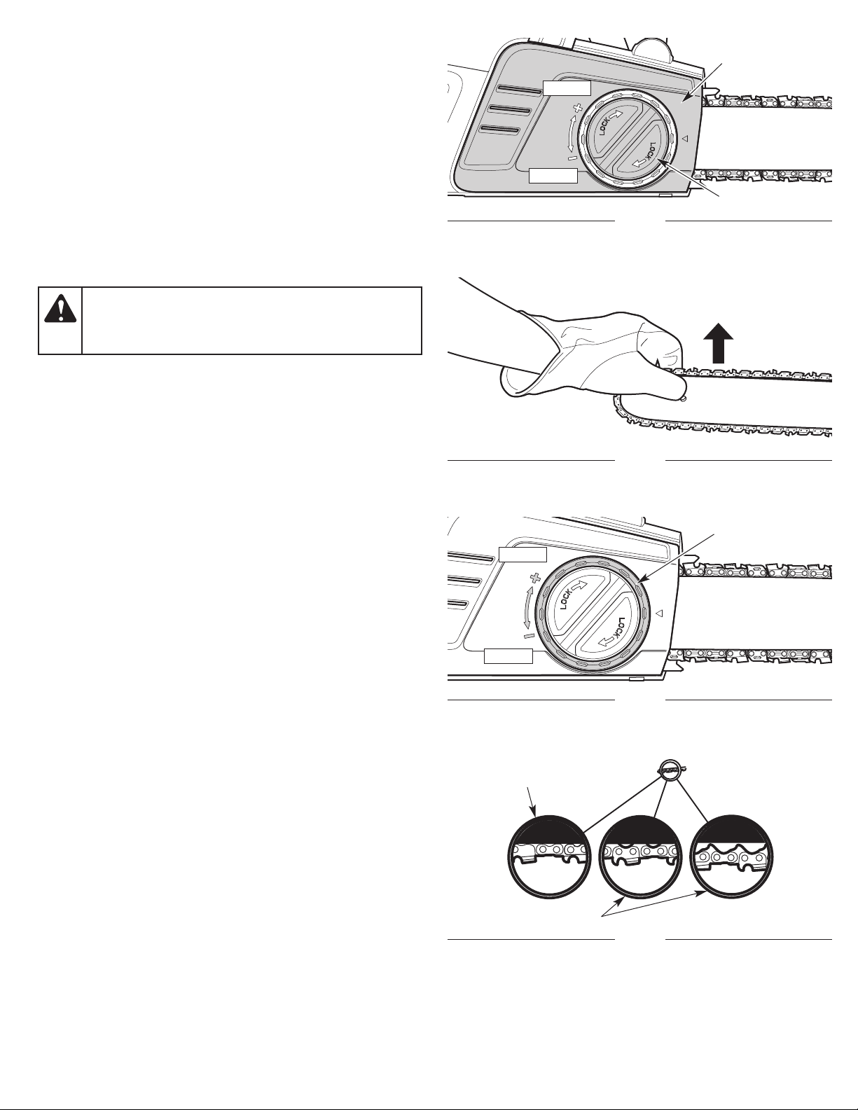
NOTE: A new saw chain tends to stretch and will need readjustment
after as few as five (5) cuts. This is normal during the break-in
period. The interval between future adjustments will lengthen
quickly.
1. Turn the bar knob counterclockwise to slightly loosen the bar
cover (Fig. 39). DO NOT remove the bar cover.
2. Hold the guide bar tip up (Fig. 40) and turn the chain-tensioning
ring to adju
st the tension (Fig. 41).
• Turn the chain-tensioning ring clockwise to tighten the saw chain.
rn the chain-tensioning ring counterclockwise to loosen the
• Tu
saw chain.
The saw chain should fit snuggly against the underside of the
guide bar. There should be no sag (Fig. 42).
3. Continue to hold the guide bar tip up (Fig. 40). Turn the bar knob
clockwise to securely tighten the bar cover (Fig. 39).
Bar Cover
Tighten
Loosen
Bar Knob
Fig. 39
CAUTION:
If the saw chain was tensioned while warm, it
may become too tight when cooled. Loosen the chain
tension after operation and check the chain tension before
the next use.
Fig. 40
Chain-Tensioning
Ring
Tighten
Loosen
Fig. 41
24
Correct Tension
Incorrect Tension
Fig. 42
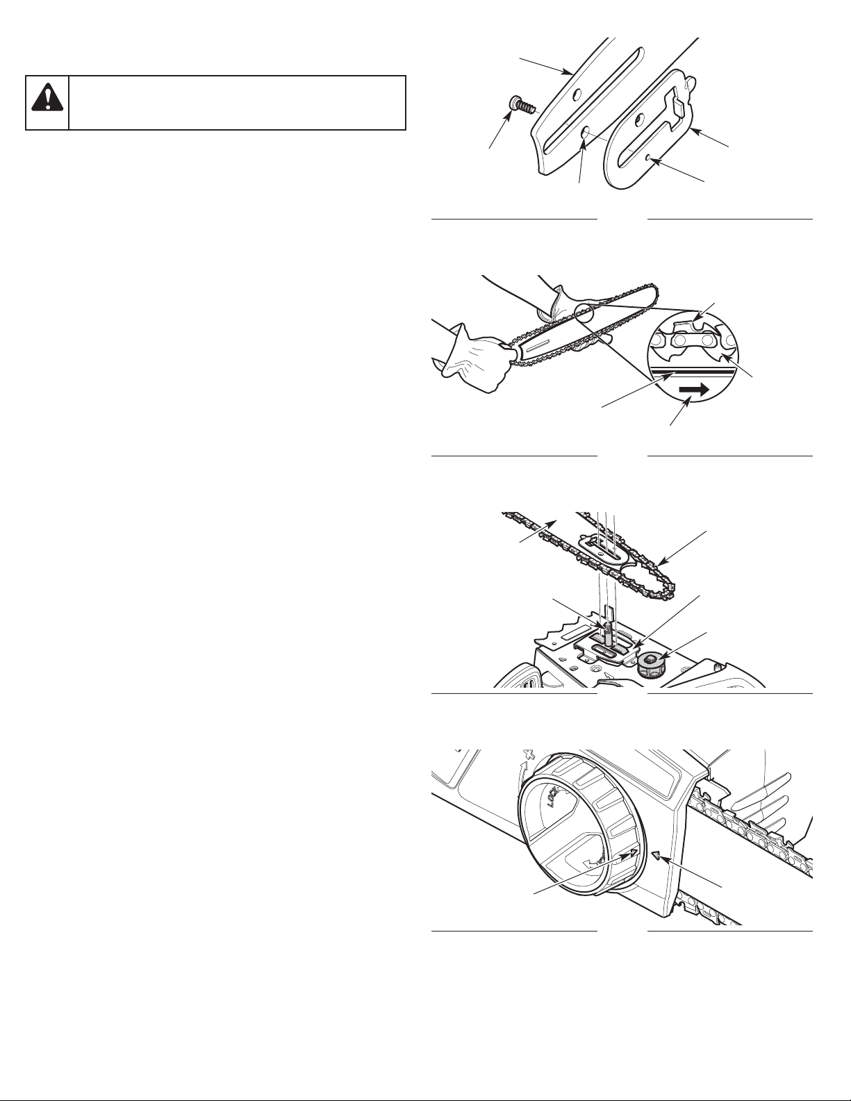
REMOVING AND INSTALLING THE GUIDE BAR AND SAW
CHAIN
Guide Bar
WARNING:
The saw chain is very sharp. Always wear
heavy-duty protective gloves when handling or performing
maintenance on the saw chain.
The guide bar and saw chain need to be removed when certain
maintenance procedures are performed, such as when rotating the
guide bar. When replacing old guide bars and saw chains with new
parts, always use the manufacturer’s specified replacement parts.
Refer to Replacing the Guide Bar and Saw Chain.
Removing the Guide Bar and Saw Chain
1. Turn the bar
. Remove the bar cover.
2
knob counterclockwise to loosen the bar cover (Fig. 39).
3. Carefully remove the saw chain and guide bar (Fig. 45).
4. Remove the saw chain from the guide bar.
5. Use a small Phillips screwdriver to remove the screw that holds
the bracket onto the guide bar (Fig. 43).
Installing the Guide Bar and Saw Chain
1. Place the bracket onto the guide bar (Fig. 43). Align the hole on
the bracke
crew into the aligned holes (Fig. 43). Tighten the screw securely
s
t with the hole on the guide bar (Fig. 43). Insert the
with a small Phillips screwdriver.
2. Set the saw chain on a clean, flat surface and straighten out any
kinks.
3. Fit the saw chain into the guide bar groove (Fig. 44). Make sure
the cutters point in the correct direction of rotation (Fig. 44). Keep
a loop of saw chain at the back end
. Hold the saw chain and guide bar together in position over the
4
of the guide bar (Fig. 44).
unit. Loop the saw chain around the drive sprocket and install
the guide bar onto the guide bar bolt (Fig. 45). Make sure the
guide bar is flush against the mounting surface (Fig. 45). Make
sure the flats on the saw chain are in the grooves on the drive
sprocket (Fig. 44).
5. Turn the chain-tensioning ring (Fig. 4
ensioning ring aligns with the arrow on the bar cover (Fig. 46).
t
1) until the arrow on the chain-
6. Place the bar cover onto the motor housing. Make sure the chain
catcher is seated securely in the slot on the bar cover (Fig. 47).
Make sure the mounting post is seated securely in the hole on
the bar cover (Fig. 47).
7. Turn the chain-tensioning ring (Fig. 41) clockwise until the bar
cover is connected to
egins to move forward.
b
the motor housing and the guide bar
8. Turn the bar knob clockwise to tighten the bar cover (Fig. 39).
DO NOT tighten the bar knob completely.
9. Make sure the saw chain is still in the guide bar groove. Adjust
the chain tension. Refer to Adjusting the Chain Tension.
10. Hold the guide bar tip up (Fig. 40). Turn the bar knob clockwise
to securely tighten the bar cover (Fig. 39).
Screw
Guide Bar Groove
Guide Bar
Guide Bar Bolt
Hole
Fig. 43
Direction of Rotation
Fig. 44
Fig. 45
Bracket
Hole
Cutter
Saw
Chain
Flat
Saw Chain
Mounting Surface
Drive Sprocket
25
Arrow
Arrow
Fig. 46
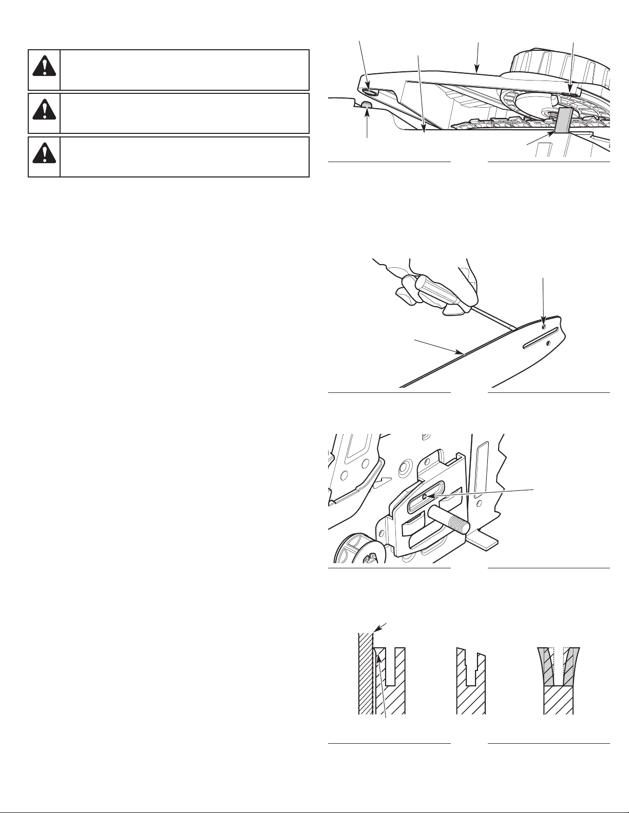
MAINTAINING THE SAW CHAIN
WARNING:
heavy-duty protective gloves when handling or performing
maintenance on the saw chain.
The saw chain is very sharp. Always wear
Hole
Motor Housing
Bar Cover
Slot
WARNING:
An improperly sharpened saw chain
increases the chance of kickback. Failure to replace or
properly maintain the saw chain can cause serious injury.
CAUTION:
A dull or improperly sharpened saw chain
can cause excessive motor speed during operation, which
can result in severe motor damage.
For safe, efficient operation, the saw chain must be maintained properly.
The saw chain will wear with use, causing the chain to stretch. This
is normal. When it is no longer possible to obtain a correct chaintension adjustment, the saw chain will need to be repaired by an
authorized service center or replaced. Refer to Replacing the Guide
Bar and Saw Chain.
Always keep the sa
ollowing indicators of a dull saw chain:
f
w chain sharp. During operation, look for the
• Wood chips are small and powdery.
• The saw chain must be forced through the wood.
• The saw chain cuts to one side.
If any of these conditions exist, sharpen or replace the saw chain.
Refer to Replacing the Guide Bar and Saw Chain.
NOTE: If you do not fully understand the process for properly
sharpening a saw chain, ha
uthorized service center or replace the saw chain.
a
ve the saw chain sharpened by an
Mounting Post
Guide Bar Groove
Chain Catcher
Fig. 47
Oil Passage
Fig. 48
MAINTAINING THE GUIDE BAR
1. Rotate the guide bar frequently, at regular intervals (for example,
after every 5 hours of operation), to ensure even wear on the top
and bottom of the guide bar. Refer to Removing and Installing
the Guide Bar and Saw Chain.
2. Clean the guide bar groove and oil passages whenever the saw
chain is removed, when the unit has been used heavily or when
the saw chain appears dirty.
Use a scre
brush or similar instrument to remove debris from the guide bar
groove (Fig. 48). Use a small, soft wire to remove any debris
from the chain oil discharge hole (Fig. 49).
NOTE: If the oil passages are clear, the saw chain will give off a
spray of oil shortly after it begins to rotate during operation.
3. Frequently check the guide bar for damage (Fig. 50). Feathering
a
nd burring of the guide bar rails (the ridges on either side of the
ar groove) is a normal process of guide bar wear. Such faults
b
should be smoothed with a file as soon as they occur (Fig. 50). A
guide bar with the following faults should be replaced:
• Wear inside the guide bar rails that permits the chain to lay
sideways
• Bent guide bar
• Cracked or broken rails
• Spread rails
Refer to Replacing the Guide
Bar and Saw Chain.
wdriver, putty knife, wire
Flat File
Bur
Fig. 49
Uneven Wear
Fig. 50
Chain Oil
Discharge Hole
Spread Rails
26
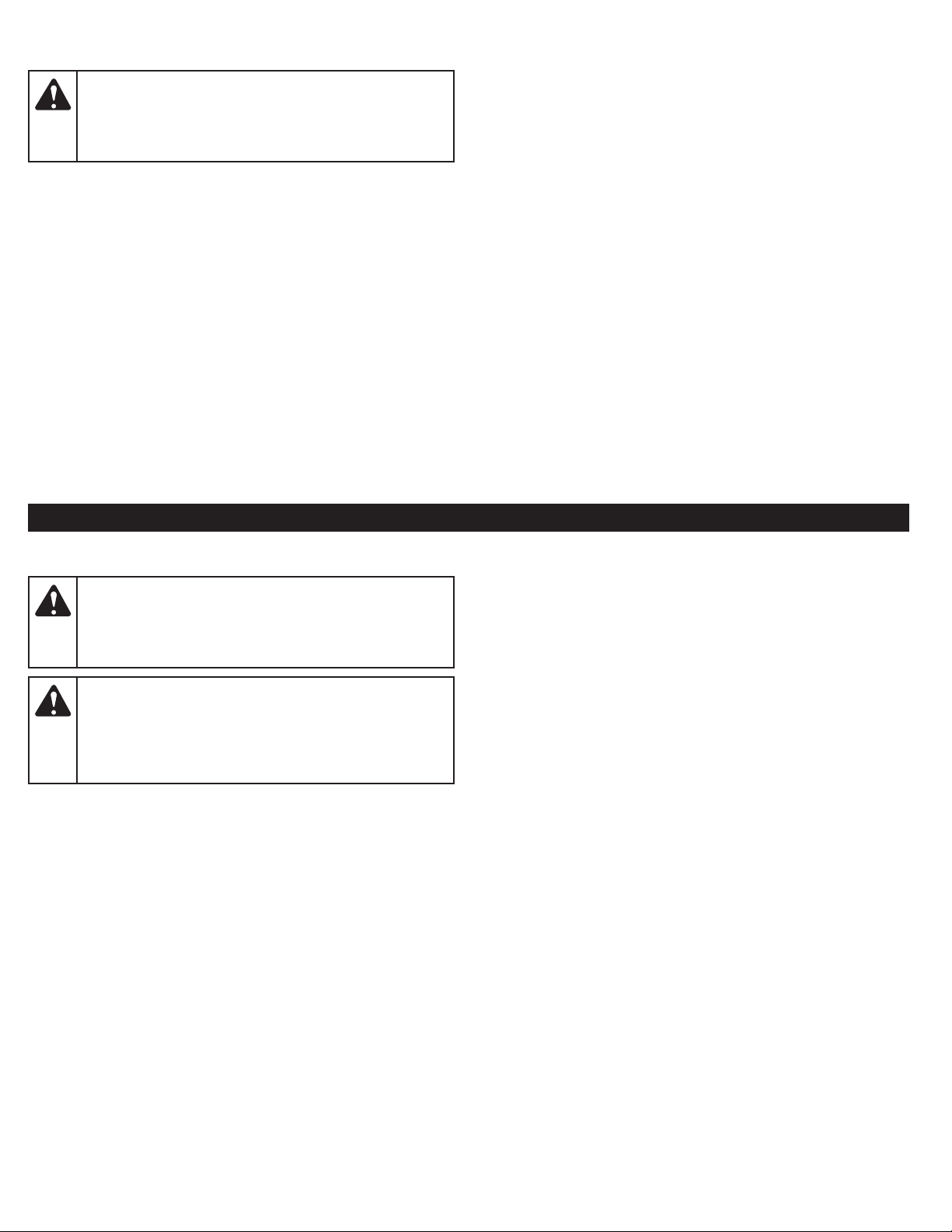
REPLACING THE GUIDE BAR AND SAW CHAIN
WARNING:
which significantly reduces the danger of kickback. Lowkickback saw chain does not completely eliminate
kickback. A low-kickback or “safety chain,” should never
be regarded as total protection against injury.
When replacing the guide bar and saw chain, only use the
replacement parts specified by the manufacturer or their
equivalents. Refer to Replacement Parts. Use of any unauthorized
parts or accessories could lead to serious injury to the operator or
damage to the unit and will VOID the warranty.
Always use a replacement saw chain designated as “low-kickback”
or a saw
re
kickback-reducing guard links) should only be used by an
experienced professional chain saw operator.
chain that meets the low-kickback performance
quirements. A standard saw chain (a chain that does not have the
Always use a low-kickback saw chain,
CLEANING AND STORAGE
CLEANING
WARNING:
unit while it is running. Always remove the battery to
prevent the unit from starting accidentally. Always allow the
unit to cool before cleaning the unit. Always unplug the
battery charger before cleaning the battery charger.
WARNING:
to clean the unit, battery or battery charger. Do not douse
the unit with water. Do not submerge the unit in water or
any other liquid. Do not use strong detergents. Household
cleaners that contain aromatic oils such as pine and lemon,
and solvents such as kerosene, can damage plastic.
1. Loosen the saw chain if the chain tension was adjusted during
operation. The saw chain will contract as the unit cools, which
could damage the unit if the chain is too tight.
2. Use a small brush or clean, dry cloth to clean the outside of the
unit, battery and battery charger.
NOTE: When preparing the unit for long-term storage (30 days or
more), remove the guide bar and s
guide bar cover, guide bar mounting surface and sprocket. Use
a firm non-wire brush to clean the guide bar groove.
Reassemble the unit.
3. Lightly coat the guide bar and saw chain with a corrosioninhibiting oil.
To prevent serious injury, never clean the
To prevent serious injury, do not use water
aw chain. Care
fully clean the
STORAGE
• Remove the battery from the unit.
• Loosen the saw chain if the chain tension was adjusted during
operation. The saw chain will contract as the unit cools, which
c
ould damage the unit if the chain is too tight.
• Allow the unit, battery and/or battery charger to cool.
• Thoroughly clean the unit, battery and battery charger. Inspect
them for any loose or damaged parts. Replace damaged parts
and tighten loose screws, nuts or bolts.
• Cover the guide bar and saw chain with the scabbard.
• Lock up the unit, battery and battery charger to prevent
unauthorized use or
tore the unit, battery and battery charger indoors, in a dry, well-
• S
ventilated area.
• Store the battery and battery charger in an area that is between
65 and 75˚ F (18 and 24˚ C).
• Always unplug the battery charger when it is not in use.
• Store the unit, battery and battery charger out of the reach of
children.
• If the battery is left unused for more than two months, fully
charge the battery bef
NOTE: It is normal for bar and chain oil to seep from the unit when not
in use. Please take this into consideration when storing the unit.
damage.
use.
ore
27

TROUBLESHOOTING
PROBLEM SOLUTION
THE BATTERY WILL NOT CHARGE
The battery charger is not plugged in Plug the battery charger into a 120V 60hz AC source
The battery is not fully inserted into the battery charger
The battery and/or charger are too hot or too cold
The battery and/or battery charger are no longer functional Refer to the Warranty section for replacement information
THE BATTERY DIES QUICKLY
The battery is not fully charged Charge the battery completely
The battery and/or battery charger are no longer functional Refer to the Warranty section for replacement information
THE MOTOR WILL NOT RUN
The battery lacks sufficient charge Charge the battery completely
The battery is not installed correctly Remove and reinstall the battery
The trigger lockout was not engaged Press and hold the trigger lockout before squeezing the trigger
Remove and then reinsert the battery into the battery charger
completely
Make sure the battery and charger are in an environment between
32° and 104° F (0° and 40° C). Allow time for the battery and/or
charger to warm up or cool down.
THE MOTOR STOPS WHILE IN USE, BUT THE BATTERY STILL HAS SUFFICIENT CHARGE
Device protection systems have engaged
THE SAW CHAIN COMES OFF THE GUIDE BAR
The saw chain tension is too loose Adjust the saw chain tension
The guide bar and saw chain are assembled incorrectly Refer to Removing and Installing the Guide Bar and Saw Chain
THE GUIDE BAR AND SAW CHAIN ARE RUNNING HOT, SMOKING OR STUCK
The saw chain tension is too tight Adjust the saw chain tension
The saw chain and guide bar lack sufficient oil Fill the chain oil reservoir
The guide bar groove and oil passages are dirty Clean the guide bar and oil passages
THE SAW CHAIN DOES NOT ROTATE
The saw chain tension is too tight Adjust the saw chain tension
The guide bar and saw chain are assembled incorrectly Refer to Removing and Installing the Guide Bar and Saw Chain
The guide bar and saw chain are damaged
The drive assembly is damaged Refer to Service information
Remove the battery, allow it to cool for 30 seconds, then reinstall
the battery
Inspect the guide bar and saw chain for damage. Replace them if
necessary
THE SAW CHAIN ROTATES, BUT DOES NOT CUT
The saw chain is dull Sharpen or replace the saw chain
The saw chain is on backwards Check and correct the saw chain direction
If further assistance is required, contact an authorized service center.
28

WARRANTY
REMINGTON LLC
LIMITED WARRANTY
Limited Warranty
The limited warranty set forth herein is given by Remington LLC with respect to new battery-powered, Remington-branded products
(hereinafter “Product”) purchased and used in the United States and/or Canada to the Initial Purchaser (as defined herein). This Product is
not intended for rental or commercial use.
Scope Of The Limited Warranty
Remington LLC of
Exclusions (defined herein), during the Warranty Period (as defined herein), this Product (exclusive of the battery and the battery charger) will
be free from manufacturing defects, including workmanship and materials. The “Initial Purchaser” is the first person to purchase this new
P
roduct from an authorized Remington dealer, distributor and/or retailer of such products. This limited warranty is non-transferable. Subject
to the Exclusions and except as otherwise set forth herein, the limited warranty period for this new Product purchased by the Initial
Purchaser is three (3) years from the date of purchase, as shown on the original sales receipt for the Product (“Warranty Period”).
fers the following limited warranty to the Initial Purc
haser for residential or otherwise non-commercial use: except for the
D
efects In Workmanship Or Materials
Subject to the Exclusions and except as otherwise set forth herein, this Product is warranted to be free from manufacturing defects in either
workmanship or materials for the Warranty Period. During the Warranty Period, Remington LLC will, at its option, either repair or replace any
original part that is covered by this limited warranty and is determine
Qualify For This Limited Warranty, This Product:
To
1. Must have been purchased from an authorized retailer.
2. Must have been purchased within the United States or Canada by the Initial Purchaser.
3. Must have been used for residential (non-commercial) purposes only.
4. Must have been used in a manner consistent with the normal and proper intended use for this
Who Can Perform Repairs Under This Warranty?
In order to qualify for the limited warranty as set forth herein, the repairs made under this warranty must be performed by an authorized
Remington warranty service provider.
How To Get Service Under This Limited Warranty.
To locate a Remington warranty service provider, contact your authorized Remington dealer, distributor, or retailer or contact
t P.O. Box 361032, Cleveland, Ohio 44136-0019 or call 1-866-206-2707 or log on to our website at www.remingtonpowertools.com. In
a
Canada, contact MTD Products Limited, 97 Kent Avenue, Kitchener, ON N2G 3R2, or call 1-877-696-5533 or log on to the above website.
This limited warranty is provided by Remington LLC and is the only product warranty provided by Remington LLC for this Product. A COPY
O
F YOUR SALES RECEIPT IS REQUIRED FOR WARRANTY SERVICE.
d to be defective in workmanship or material.
duct.
Pro
Remington LLC
What This Limited Warranty Does Not Cover.
This Limited Warranty Does Not Cover The Following (the “Exclusions”):
1. Product purchased outside of the United States or Canada.
2. Damage due to lack of maintenance and/or improper maintenance as described in the operator’s manual.
3. Normal wear and tear resulting from use of the Product.
29
 Loading...