

Remington HH- 45-KFA, HH-75T-KFA, HH-125T-KFA, HH-175T-KFA, HH-215T-KFA User's Manual & Operating Instructions
Page 1
DANGER
DANGER
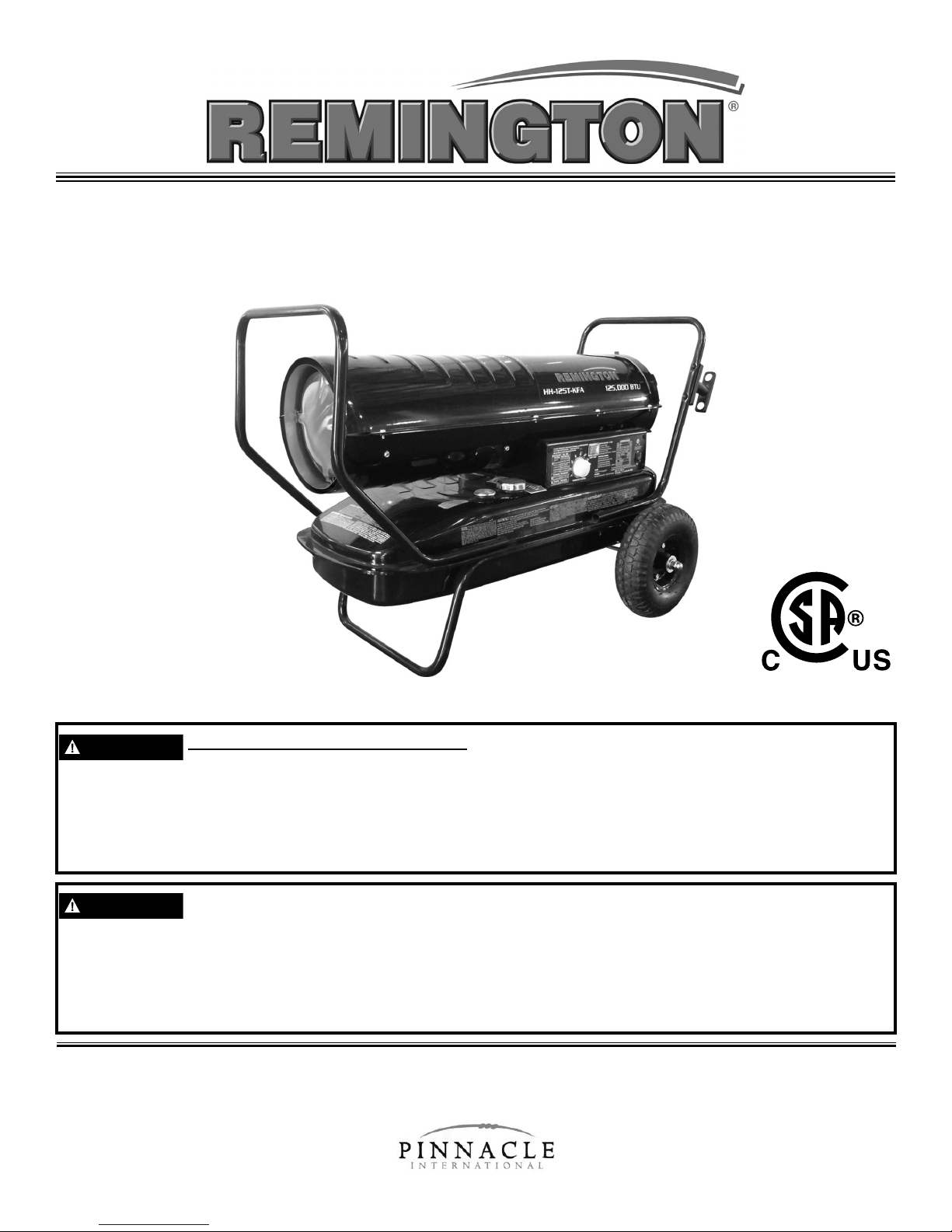
User’s Manual & Operating Instructions
Model Numbers
HH- 45-KFA / HH-75T-KFA / HH-125T-KFA / HH-175T-KFA / HH-215T-KFA
FACTORY ID: 001
CONSUMER: READ AND SAVE THESE INSTRUCTIONS
GENERAL HAZARD WARNING:
READ AND UNDERSTAND ALL OF THE INSTRUCTIONS IN THIS MANUAL
BEFORE ASSEMBLING, STARTING, OR SERVICING THE HEATER. Be sure to comply with the
instructions and warnings provided with this heater. Failure to comply can result in fire or explosion
that can cause property loss, bodily injury, or loss of life. Only persons who can follow and
understand these instructions should operate or service this heater. If you need heater info; such as
an operating manual, labels, etcetera, contact Pinnacle Products International at 800-641-6996.
NOT FOR USE IN RESIDENTIAL LIVING AREAS OR IN ENCLOSED SPACES
WITHOUT ADEQUATE VENTILATION. FOR OUTDOOR USE. INDOOR USE
PERMITTED ONLY FOR: THE TEMPORARY HEATING OF ADEQUATELY VENTILATED
BUILDINGS OR STRUCTURES UNDER CONSTRUCTION, ALTERATION OR REPAIR. This is
an unvented portable heater that uses air (Oxygen) from within the area in which it is used. Failure
to provide adequate combustion and ventilation air will result in asphyxiation, carbon monoxide
poisoning, bodily injury or death. Refer to “Ventilation” on Page 7.
© 2015 Pinnacle Products International, Inc.
668 Stony Hill Road #302 Yardley, PA 19067 USA • Toll Free (800)-641-6996
Fax: (215)-891-8461 • Web: www.protemp.us • Email: info@pinnacleint.com
701000129-15
Page 2
NEVER LEAVE HEATER UNATTENDED WHILE BURNING OR
WARNING
WARNING
WARNING
WARNING
WARNING
WHILE CONNECTED TO A POWER SOURCE
Table Of Contents
Safety Information.............................................1-2
Features and Specications.................................3
45-KFA and 75T-KFA Assembly...........................4
125T/ 175T / 215T-KFA Assembly....................5-6
Operation..........................................................7-6
Ventilation.............................................................7
Maintenance....................................................9-11
Wiring Diagram...................................................11
Troubleshooting Guide.......................................12
Exploded View...................................................13
Parts List............................................................14
Warranty..............................................Back Cover
Safety Information
FIRE, BURN, INHALATION AND EXPLOSION HAZARD. Keep combustibles such
as; building materials, paper or cardboard a safe distance away from the heater
as recommended by these instructions. Never use the heater in spaces which contain products
such as; gasoline, solvents, paint thinners, dust particles, volatile or airborne combustibles or any
unknown chemicals. This is an unvented portable heater. It uses air (Oxygen) from the area in
which it is used. Adequate combustion and ventilation air must be provided. Refer to “Ventilation” on
page 7. Bulk fuel storage should be a minimum of 25 feet from heater.
DO NOT OPERATE THIS HEATER UNTIL YOU HAVE READ AND THOROUGHLY
UNDERSTAND THESE SAFETY AND OPERATING INSTRUCTIONS.
Failure to comply with the precautions and instructions provided with this heater can result in death,
serious bodily injury, property loss or damage from the hazards of fire, soot production, explosions,
burns, asphyxiation or carbon monoxide poisoning. Only persons who can read and understand
these instructions should use or service this heater.
DO NOT START THE HEATER WHEN EXCESS OIL HAS ACCUMULATED.
DO NOT START THE HEATER WHEN THE CHAMBER IS HOT.
CALIFORNIA RESIDENTS: This product contains chemicals, including lead, known
to the State of California to cause birth defects or other reproductive harm.
Wash hands after handling.
MASSACHUSETTS RESIDENTS: Massachusetts state law prohibits the use of this heater in
any building which is used in whole or in part for human habitation. Use of this heating device in
Massachusetts requires local fire department permit (M.G.L.C. 148, Section 10A).
NEW YORK CITY RESIDENTS: The New York City Fire Code prohibits the storage, handling
and use of kerosene fueled heaters for space heating. Any person violating that provision may be
punished by a fine up to $10,000 and a term of imprisonment of up to 6 months.
THE INSTALLATION OF THIS HEATER SHALL COMPLY WITH THE REGULATIONS OF THE
AUTHORITIES HAVING JURISDICTION.
Look for this icon throughout the manual for helpful tips on how to
assemble, use and clean your KFA Heater.
© 2015, Pinnacle Products International, Inc. Kerosene Forced Air Heater User’s Manual
1
Page 3
NEVER LEAVE HEATER UNATTENDED WHILE BURNING OR
WARNING
DANGER
WARNING
WARNING
WARNING
WHILE CONNECTED TO A POWER SOURCE
Safety Information
RISK OF INDOOR AIR
POLLUTION!
The products described in this manual are
kerosene direct-red, forced air heaters. Kerosene
forced air heaters are primarily intended for use for
temporary heating of buildings under construction,
alteration or repair. Direct-red means that all of
the combustion products of the heater enter the
heated space. This appliance is rated at 98%
combustion efciency, but does produce small
amounts of carbon monoxide.
CARBON MONOXIDE POISONING
MAY LEAD TO DEATH!
Carbon monoxide is toxic. Humans can tolerate
only small amounts of carbon monoxide and so
precautions should be taken to provide proper
ventilation. Failure to provide proper ventilation
in accordance with the instructions in this manual
can result in death.
People with breathing problems should consult a
physician before using this heater.
Early signs of carbon monoxide poisoning
resemble the u. Symptoms of improper ventilation
/ carbon monoxide poisoning are:
Headache • Dizziness • Nausea
Sore Throat
• Burning of Nose and Eyes
• Dry Mouth
If you experience any of these symptoms:
GET FRESH AIR AT ONCE! Have your heater
serviced and check for proper ventilation. Some
people are more affected by carbon monoxide
than others. These include: pregnant women,
those with heart or lung problems, anemia or those
under the influence of alcohol or at high altitudes.
FOR OUTDOOR USE. INDOOR USE
PERMITTED ONLY FOR: The temporary
heating of adequately ventilated buildings or
structures under construction, alteration or
repair! Provide at least a three square foot
(2,800 sq cm) opening of outside air for
every 100,000 Btu / Hr heater rating. Refer to
“Ventilation” on page 7 for further instructions.
RISK OF ELECTRIC SHOCK!
ALWAYS use only the electrical power (voltage and
frequency) specified on the model plate of the heater.
ALWAYS use only three-prong, grounded outlet and
extension cord.
ALWAYS use only 14 AWG or better extension cord.
ALWAYS unplug the heater when not in use.
ALWAYS install the heater so that it is not directly
exposed to water spray, rain, dripping water, or wind.
RISK OF BURNS, FIRE AND
EXPLOSION!
NEVER use fuels such as gasoline, benzine, paint
thinners or other oil compounds in this heater.
NEVER refill the heater’s fuel tank while the
heater is operating or still hot. This heater is
EXTREMELY HOT while in operation.
NEVER block air inlet (rear) or air outlet (front).
NEVER use duct work in front or rear of heater.
NEVER move or handle heater while still hot.
NEVER transport heater with fuel in tank.
NEVER use with an external fuel tank.
CAUTION! HOT WHILE IN
OPERATION. DO NOT TOUCH.
KEEP CHILDREN, ANIMALS, CLOTHING AND
COMBUSTIBLES AWAY FROM HEATER.
Keep all combustible materials away from this heater.
Minimum Clearance From Combustibles
45-KFA 75T-KFA 125T-KFA 175T-KFA 215T-KFA
Top
Sides
Front
4 ft. 4 ft. 4 ft. 4 ft. 4 ft.
4 ft. 4 ft. 4 ft. 4 ft. 4 ft.
8 ft. 8 ft. 8 ft. 8 ft. 10 ft.
ALWAYS locate heater on a stable and level surface.
If your heater is equipped with a thermostat,
once it is plugged in, it can start at anytime in
accordance with the thermostat setting.
© 2015, Pinnacle Products International, Inc. Kerosene Forced Air Heater User’s Manual
2
Page 4
NEVER LEAVE HEATER UNATTENDED WHILE BURNING OR
Hot Air Outlet
Upper Shell
Lower Shell
Fuel Tank
Fan Guard
Optional Pressure Gauge
Fuel Gauge
Fuel Cap
Side Cover
Thermostat Knob
(PT-70T-KFA only)
Lamp
Power Cord
Power/Reset Switch
Handle
Optional
Extension
Cord Wrap
Optional Electric Outlet
(120V 5amp max non fused)
WHILE CONNECTED TO A POWER SOURCE
Specications
Model # HH-45-KFA HH-75T-KFA
Rating: Btu/Hr 45,000 70,000 125,000 175,000 215,000
Fuel Consumption: Gal/Hr .35 .53 .95 1.33 1.63
Fuel Tank Capacity: Gallons
Pump Pressure: psi 3.0 4.0 5.0 7.5 9.0
Volts: AC/Hz
Amps 1.4 1.5 2.3 2.7 2.8
Phase
5.0 5.0 10.0 13.0 13.0
120VAC / 60Hz 120VAC / 60Hz 120VAC / 60Hz 120VAC / 60Hz 120VAC / 60Hz
Single Single Single Single Single
Specications subject to change without notice.
HH-125T-KFA HH-175T-KFA HH-215T-KFA
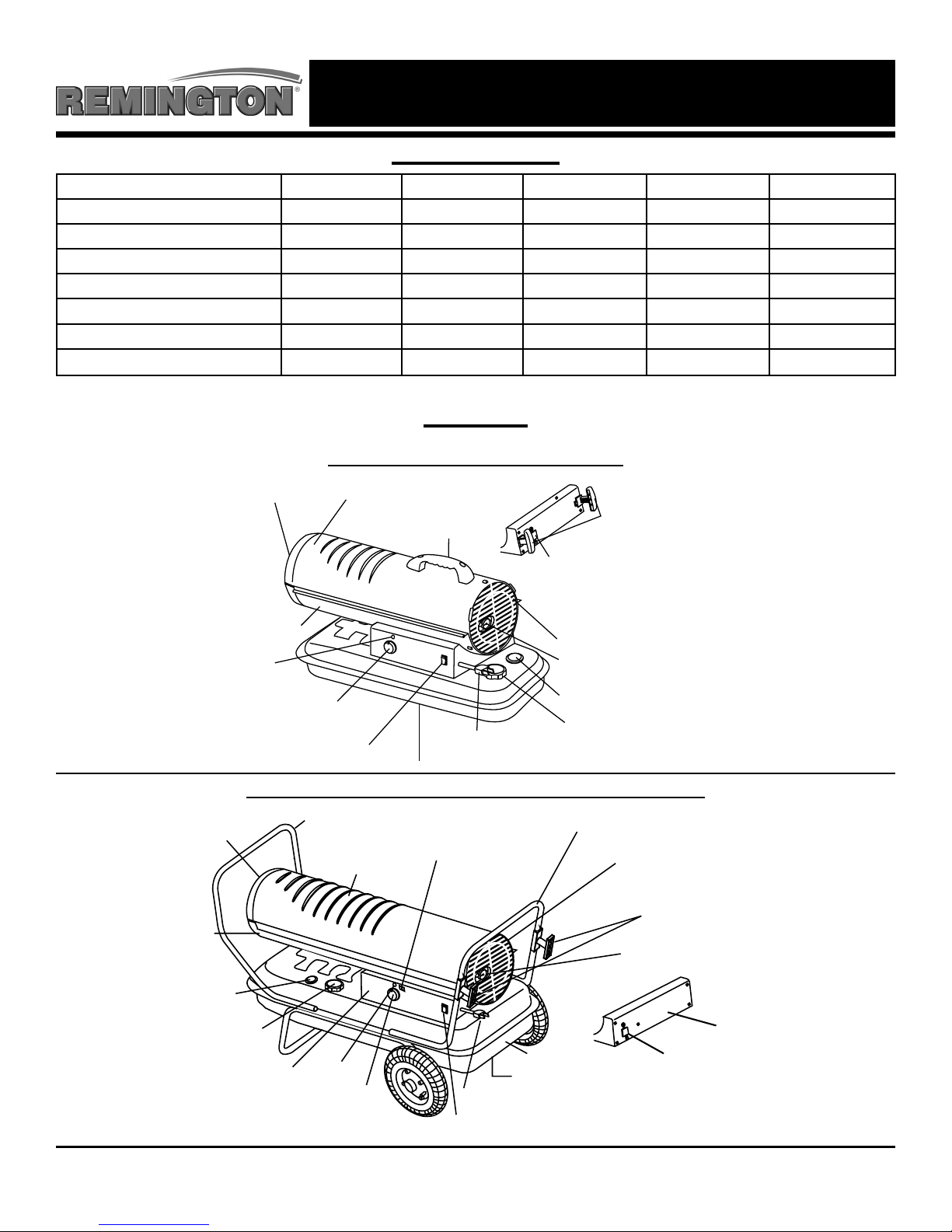
Features
Actual product features are subject to change due to ongoing improvements
Models: HH-45-KFA / HH-75T-KFA
Figure 1
Models: HH-125T-KFA / HH-175T-KFA / HH-215T-KFA
Front Handle
Hot Air Outlet
Lower Shell
Fuel
Gauge
Fuel Cap
Side Cover
Lamp
Thermostat Knob
Figure 2
© 2015, Pinnacle Products International, Inc. Kerosene Forced Air Heater User’s Manual
Upper Shell
Digital
Temperature
Display
Fuel Tank
Drain Plug
Power Cord
Power/Reset Switch
3
Rear Handle
Fan Guard
Optional Extension
Cord Wrap
Optional Pressure Gauge
Side Cover
Optional Electrical
Outlet (120V 5amp
max non-fused)
Page 5
NEVER LEAVE HEATER UNATTENDED WHILE BURNING OR
WHILE CONNECTED TO A POWER SOURCE
Assembly Instructions
Models: HH-45-KFA / HH-75T-KFA
- Remove the heater and all packaging materials
from the shipping carton
Note: Save the box and packaging materials
for future storage.
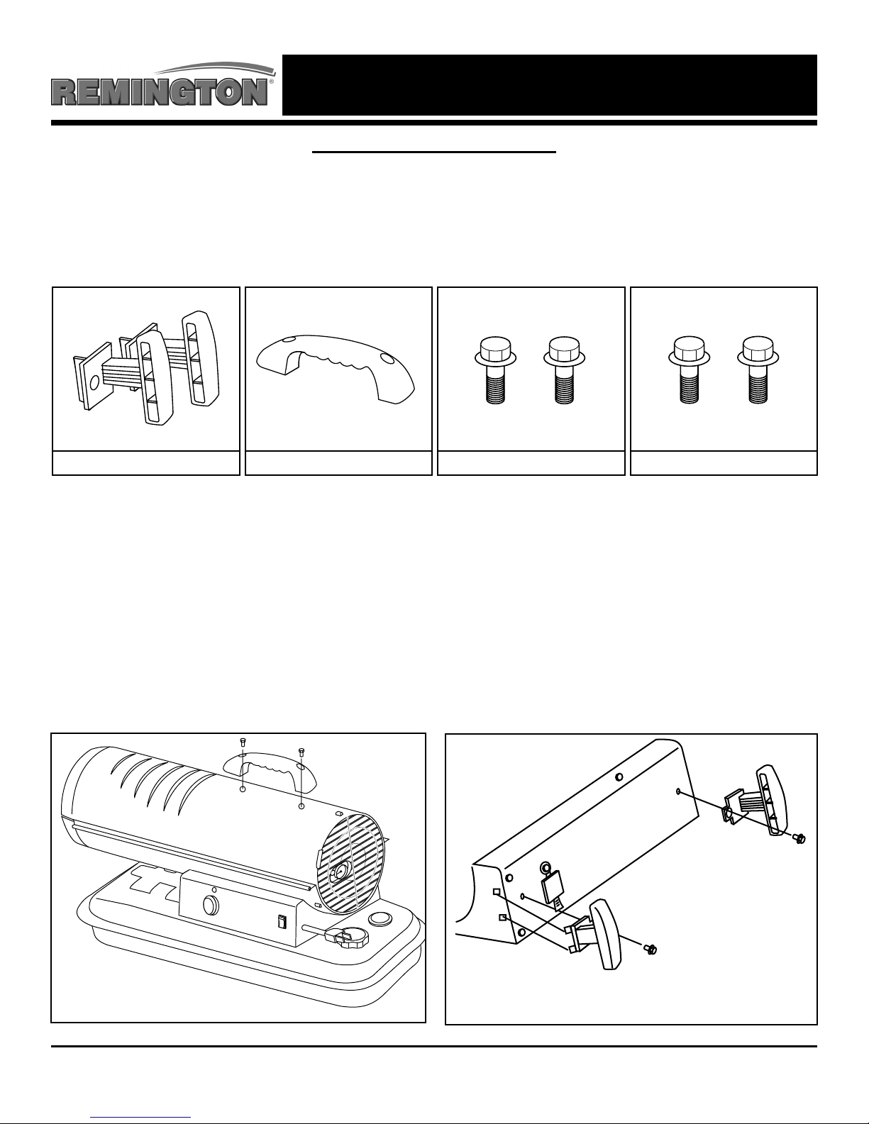
What’s In The Box
Cord Wraps (Optional) Carry Handle (1) 10 mm Screws (2) 13 mm Screws (2)
Missing Parts? Please Call 800-641-6996 For Assistance
Carry Handle Assembly
1. Align holes in the upper housing with the 2
holes in the handle as shown in Figure 3.
2. Insert screws (13 mm) and tighten firmly.
Optional Cord Wrap Assembly
1. Insert tabs into square slots in shell support
and line up screw holes as shown in Figure 4.
2. Insert screws (10 mm) and tighten firmly.
Tools Needed:
- Phillips Head Screw Driver
Figure 3
© 2015, Pinnacle Products International, Inc. Kerosene Forced Air Heater User’s Manual
Figure 4
4
Shown With Optional Cord Wraps and Power Outlet
Page 6
NEVER LEAVE HEATER UNATTENDED WHILE BURNING OR
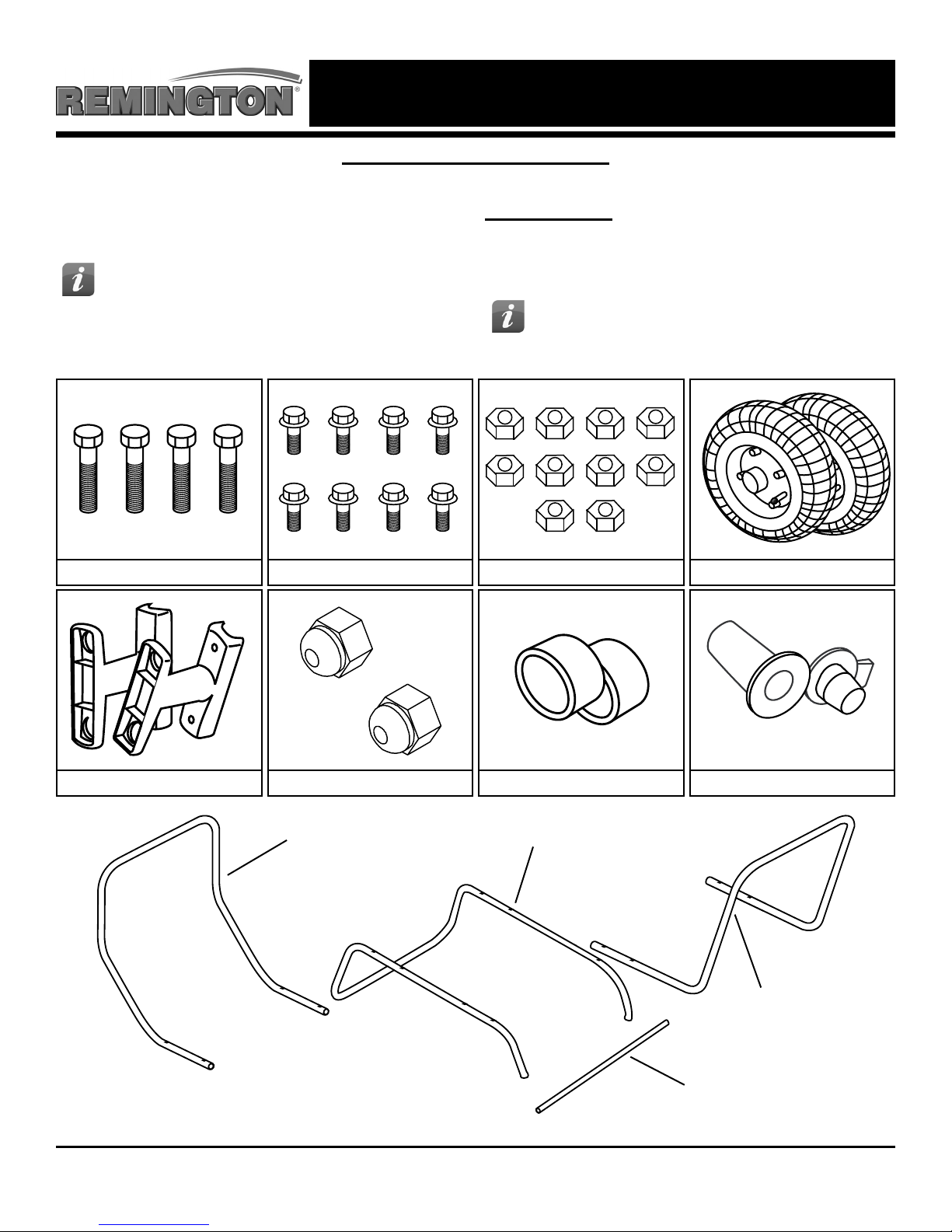
Assembly Instructions
Models: HH-125T-KFA / HH-175T-KFA / HH-215T-KFA
- Remove the heater and all packaging
materials from the shipping carton.
Tip: Be sure to remove the axle from the
side of the Styrofoam packaging.
WHILE CONNECTED TO A POWER SOURCE
Tools Needed:
- Phillips Head Screw Driver
- 8 mm open end wrench
- 19 mm open end wrench
Tip: Use a power screwdriver and
locking wrench for easier assembly.
What’s In The Box
50 mm Screws (4) 30 mm Screws (8) 8 mm Nuts (12) Tires (2)
Cord Wraps (Optional) Axle Nuts (2)
Front Handle
Spacers (2) Washers (2)
Wheel Support Frame
Spare Drain Plug (1)
Rear Handle
Missing Parts? Please Call 800-641-6996 For Assistance
© 2015, Pinnacle Products International, Inc. Kerosene Forced Air Heater User’s Manual
Axle
5
Page 7
NEVER LEAVE HEATER UNATTENDED WHILE BURNING OR
WHILE CONNECTED TO A POWER SOURCE
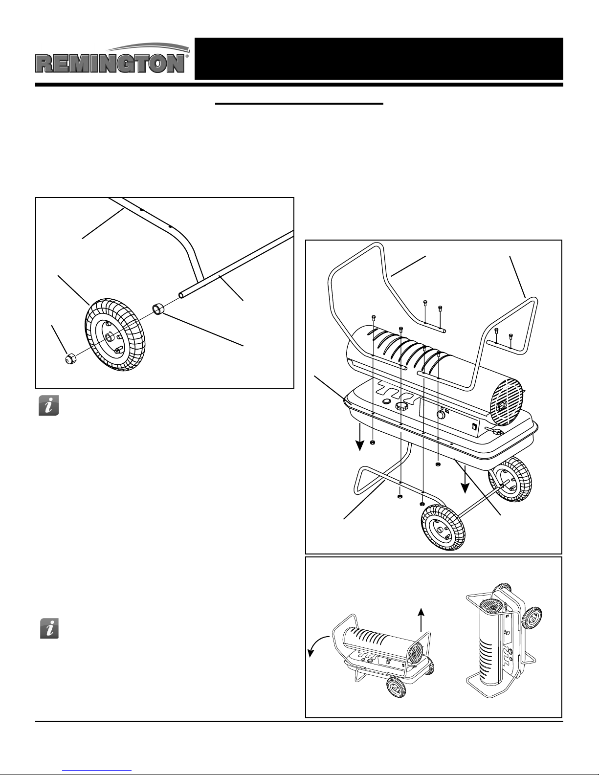
Assembly Instructions
Models: HH-125T-KFA / HH-175T-KFA / HH-215T-KFA
1. Insert axle through holes in wheel support.
2. Slide spacer onto axle.
3. Slide wheel onto axle with the air valve facing
out and hold in place with the axle nuts. (See
Figure 5).
Wheel Support Frame
Tire
Axle
Axle Nut
9. Remove the wheels to secure the second set
of screws through the rear handle.
10. Secure the rear handle with (2) short screws
(30 mm) and (2) nuts and tighten firmly
11. Replace wheels with the valve facing out and
tighten with the wheel nuts.
12. Tilt heater back down onto wheels and check
all screws and nuts to make sure they are
secure.
Front Handle Rear Handle
Spacer
Figure 5
Tip: Do not tighten the nuts fully. You will
need to remove the wheels in a later step.
4. Place heater on wheel support and line up
holes on the fuel tank lip.
5. Attach front handle with (2) long screws
(50 mm) and (2) nuts through the second
hole from the front on both sides of the tank
lip and wheel support frame and tighten
firmly.
6. Insert (2) short screws (30 mm) through the
first hole from the front in the tank lip and
tighten firmly. Make certain all (4) screws are
secure.
7. Attach rear handle with (2) long screws
(50 mm) and (2) nuts through the third hole
from the rear of the heater on either side.
(See Figure 6)
Tip: You will secure the back of the rear
handle in a later step by tilting the heater
up the front handle as shown in figure 7
Tank Lip
Wheel Support Frame
Figure 6
1 2
Unused Hole
8. Tilt the heater up gently so it is resting on the
front handle.
NOTE: DO NOT do this if there is fuel in the tank.
© 2015, Pinnacle Products International, Inc. Kerosene Forced Air Heater User’s Manual
Figure 7
6
Page 8

NEVER LEAVE HEATER UNATTENDED WHILE BURNING OR
CAUTION
DANGER
DANGER
WARNING
WHILE CONNECTED TO A POWER SOURCE
Operation
Fueling The Heater:
Kerosene (1-K)
For optimal performance of this heater, it is
strongly suggested that 1-K kerosene be used.
1-K kerosene has been rened to virtually
eliminate contaminants, such as sulfur, which can
cause a rotten egg odor during the operation of
the heater. Using diesel fuel can cause excess
soot production. Do not use Bio-Diesel as this
fuel will damage your heater’s seals and lter.
- CSA certified for use with 1-K kerosene,
no. 1 & no. 2 diesel, JP8/Jet A Fuel,
no. 1 and no. 2 fuel oil.
DO NOT use any fuel that is not approved above.
NEVER REFUEL THIS HEATER
WHILE IT IS HOT OR
OPERATING. FIRE OR EXPLOSION COULD
RESULT.
NEVER FILL THE FUEL TANK
INDOORS. ALWAYS FILL
THE TANK OUTDOORS. BE SURE THAT
THE HEATER IS ON LEVEL GROUND WHEN
FUELING, AND NEVER OVERFILL THE TANK.
DO NOT USE GASOLINE OR
CRANKCASE DRAININGS.
NOTE: Kerosene should only be stored in a blue
container that is clearly marked “Kerosene.”
Never store kerosene in a red container. Red is
associated with gasoline.
Ventilation:
- Risk of indoor air pollution and Carbon
Monoxide Poisoning. Use heater only in well
ventilated areas.
- Refer to Safety Information on pages 1-2 for
information about Carbon Monoxide Poisoning.
CARBON MONOXIDE POISONING
MAY LEAD TO DEATH!
- ALWAYS provide a fresh air opening in the heated
space of at least three square feet (2,800 sq. cm)
for each 100,00 Btu / Hr. of heater output. Provide
a larger opening if more heaters are being used.
Minimum Ventilation Opening Needed
45-KFA 75T-KFA 125T-KFA 175T-KFA 215T-KFA
1.4 ft.² 2.1 ft.² 3.8 ft.² 5.3 ft.² 6.5 ft.²
1250 cm² 1950 cm² 3480 cm² 3760 cm² 5990 cm²
- NEVER use fuel such as, benzene, alcohol, white
glass, camp stove fuel, paint thinners, or other oil
compounds in this heater. THESE ARE VOLATILE
FUELS THAT CAN CAUSE A FIRE OR
EXPLOSION.
- NEVER store kerosene in the living space.
Kerosene should be stored in a well ventilated area
outside the living area.
- NEVER store kerosene in direct sunlight or near a
source of heat.
- NEVER use kerosene that has been stored from
one season to the next. Kerosene deteriorates
over time. OLD KEROSENE WILL NOT BURN
PROPERLY IN THIS HEATER.
© 2015, Pinnacle Products International, Inc. Kerosene Forced Air Heater User’s Manual
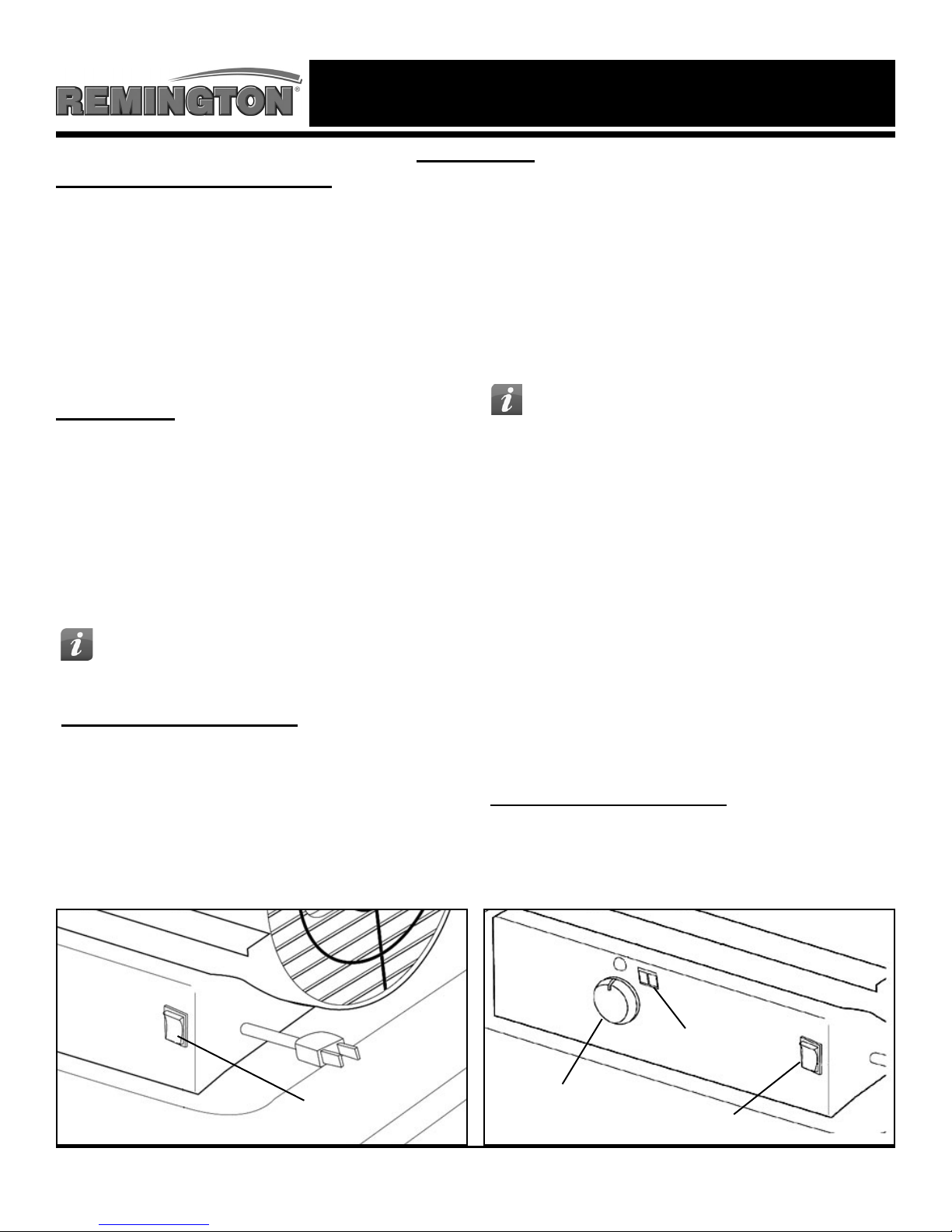
Optional Electrical Outlet:
- Never plug an appliance with more than a 5 amp
rating into this outlet (See Figure 8).
- Always keep outlet covered when not in use.
Optional Electrical Outlet
Figure 8
7
Page 9
NEVER LEAVE HEATER UNATTENDED WHILE BURNING OR
WHILE CONNECTED TO A POWER SOURCE
Operation
Starting the Heater: (Ignition)
1. Fill the tank with kerosene or other approved
fuel until needle on fuel gauge points to “F”.
2. Replace fuel cap and tighten firmly.
3. Connect the heater to a three prong
(grounded) power source. You must use a
three prong (grounded) extension cord that
is at least 6 feet long and is a minimum of 14
AWG rating.
Model 45-KFA:
1. Complete steps 1-3 above.
2. Move power switch to “On” position. The
power indicator light will illuminate and the
heater will ignite. (See Figure 9)
Models 75T-KFA / 125T-KFA / 175T-KFA / 215T-KFA:
1. Complete “starting heater ignition” steps 1-3
above
2. Turn thermostat control knob to desired
temperature setting. The thermostat set range
is from 40 ºF to 110 ºF.
3. Move power switch to “On” position. The
power indicator light and room temperature
display will illuminate and heater will ignite.
(See Figure 10)
TIP: If the heater does not ignite, the
thermostat may be set too low. Turn
the control knob to a higher setting until the
heater ignites. If the heater does not ignite;
move switch to “Off” position, check steps 1-3
above and then move switch to “On” position.
NOTE: If if the heater still does not ignite, refer to
“Troubleshooting Guide” on page 12.
TIP: If the heater does not ignite; move
switch to “Off” position, check steps 1-3
above and then move switch to “On” position.
Stopping / Restarting Heater:
- To stop the heater, move the power switch to the
“Off” position and unplug the power cord.
- To restart the heater; wait 10 seconds and follow
ignition steps.
NOTE: If if the heater still does not ignite, refer to
“Troubleshooting Guide” on page 12.
NOTE: The 45-KFA and 75T-KFA do not have a room
temperature display feature.
The room temperature display will indicate the
following:
- When the temperature is less than 0 ºF the
display says “LO”.
- When the temperature is more that 99 ºF the
display says “HI”.
- Between 0 °F and 99 °F the display shows
actual temperature.
Stopping / Restarting Heater:
- To stop the heater, move the power switch to the
“Off” position and unplug the power cord.
- To restart the heater; wait 10 seconds and follow
ignition steps.
Power Switch
Figure 9
© 2015, Pinnacle Products International, Inc. Kerosene Forced Air Heater User’s Manual
Thermostat Knob
Figure 10
8
Temperature Display
Power Switch
Page 10
NEVER LEAVE HEATER UNATTENDED WHILE BURNING OR
WARNING
WHILE CONNECTED TO A POWER SOURCE
Maintenance
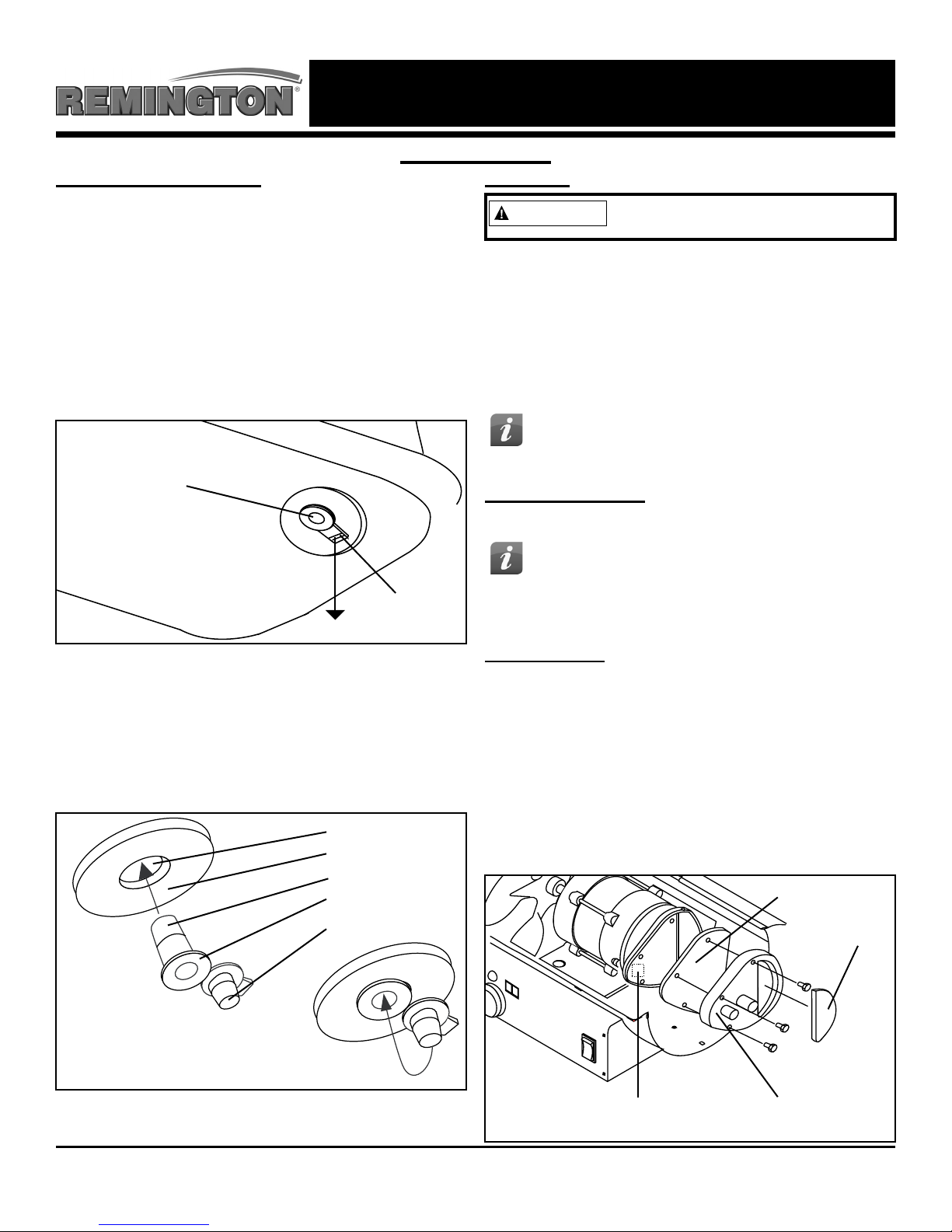
Long Term Storage:
Models 45-KFA / 75T-KFA:
1. Use an approved siphon to drain fuel through the
fuel cap opening.
Models 125T-KFA / 175T-KFA / 215T-KFA:
1. Drain fuel through the drain plug in the bottom
of the fuel tank.
2. To remove the drain plug, pull the plug grip
downward and remove the seal head from the
drain hole in the tank. (See Figure 11)
Service:
Never service heater while it is
plugged in or hot!
DO NOT TAMPER WITH THE UNIT. HAVE
A COMPETENT SERVICEMAN MAKE ANY
NECESSARY ADJUSTMENT OR REPAIRS.
Use only original equipment parts. The use of
alternate or third party components can cause unsafe
operating conditions and will void your warranty.
TIP: To order OEM parts call (800)-641-6996
Drain Plug
Drain Plug Grip
Figure 11
(Pull Down)
3. Using a small amount of kerosene, rinse and
swirl the kerosene inside of the fuel tank,
empty the tank fully.
4. To replace the drain plug; push the drain head
fully into the drain hole and secure by pushing
the seal cap fully into the head hole.
(See Figure 12)
Drain Plug
Fuel Tank
Seal Head
Head Flange
Seal Cap
We suggest following a maintenance schedule as follows:
FUEL / FUEL TANK:
Flush tank every 200 hours of operation or as needed.
TIP: Follow the long term storage
instructions to ush the tank.
DO NOT ush with water, use fresh 1-K kerosene only.
AIR FILTERS:
The air intake lter should be replaced or washed
with soap and water and dried thoroughly every 500
hours of operation or less depending on conditions.
The output and lint lters should be replaced
every 500 hours of operation or less depending
on conditions.
NOTE: Use of diesel fuel may require
additional maintenance
Air Output Filter
Intake Filter
Figure 12
IMPORTANT: Never store leftover kerosene between
seasons, using old fuel can damage heater.
© 2015, Pinnacle Products International, Inc. Kerosene Forced Air Heater User’s Manual
Lint Filter End Filter
Figure 13
9
Page 11

NEVER LEAVE HEATER UNATTENDED WHILE BURNING OR
X
X
WHILE CONNECTED TO A POWER SOURCE
Maintenance
Service (Continued):
FAN BLADES:
Blades should be cleaned at least once per
heating season, depending on conditions.
Remove all accumulated dust and dirt with a
damp cloth, taking care not to bend any of the
fan blades. Be sure the blades are dry before
re-starting the heater. For fan assembly removal
see Figure 14.
Set Screw
Motor Shaft
SPARK PLUG:
Clean and re-gap every 600 hours of operation, or
replace as needed. After removing the spark plug,
clean the terminals with a wire brush. Re-gap the
terminals to 0.140” (3.5mm) See Figure 16.
Spark Plug
Burner Head
Gap
Fan Blade
Figure 14
FUEL FILTER:
The fuel filter should be cleaned at least twice
per heating season. Clean the filter by rinsing
it in clean 1-K Kerosene. Contaminated fuel
could make cleaning the fuel filter necessary
immediately.
NOTE: To remove the filter from models 45 /
75T-KFA turn filter 90º clockwise. To remove
the filter from models 125T / 175T / 215T-KFA
turn filter 90º counter-clockwise. See Figure 15.
Fuel Filter
Fuel Line
Side Cover
Figure 16
Ignitor Wire
PHOTOCELL:
The photocell should be cleaned using a cotton
swab dipped in alcohol or water at least once
per heating season, or more depending on
conditions. See Figure 17.
Photocell
Photocell Wire
Photocell lens
Figure 15
© 2015, Pinnacle Products International, Inc. Kerosene Forced Air Heater User’s Manual
Figure 17
10
Page 12

NEVER LEAVE HEATER UNATTENDED WHILE BURNING OR
WHILE CONNECTED TO A POWER SOURCE
Maintenance
PUMP PRESSURE:
While heater is operating, turn adjusting screw
clockwise to increase, counter-clockwise to
decrease pressure. Correct pump pressure is as
follows:
Model Number Pump Pressure
HH-45-KFA 3.0 PSI
HH-75T-KFA 4.0PSI
HH-125T-KFA 5.0 PSI
HH-175T-KFA 7.5 PSI
HH-215T-KFA 9.0 PSI
Tolerance ± 10%
Pressure Valve
Adjusting Screw
Figure 18
Wiring Diagrams
45-KFA Without Optional Power Outlet
NOZZLES:
Nozzles should be cleaned or replaced at least
once per heating season. Contaminated fuel could
make this necessary immediately. To clean dirt
from nozzle, blow compressed air through nozzle
front. It may be necessary to soak the nozzle in
1-K kerosene to loosen any dirt particles.
Nozzle Face
Figure 19
Nozzle
Burner Head
75T / 125T / 175T / 215T-
KFA With Optional Power Outlet
© 2015, Pinnacle Products International, Inc. Kerosene Forced Air Heater User’s Manual
75T / 125T / 175T / 215T-
11
KFA Without Optional Power Outlet
Page 13

NEVER LEAVE HEATER UNATTENDED WHILE BURNING OR
WHILE CONNECTED TO A POWER SOURCE
Troubleshooting Guide
Locating Your Serial Number:
Your serial number can be found on a white label on the right side cover of your heater. It will begin
with 2 digits, the letter “H” followed by 6 digits. For Example: 13H123456. Have your Serial Number
ready before calling customer service at 800-641-6996.
Problem Possible Cause Solution
Heater Ignites, but main PCB shuts
off after a short period of time.
Lamp ickers and LED display
shows “E1”.
Heater will not operate or motor
runs for a short time.
Lamp ickers and LED display
shows “E1”.
Fan does not operate when heater
is plugged in and power switch is
in the “ON” position. The lamp is
ickering or and LED display shows
“E1” or “E2”.
Lamp is ickering and LED display
shows “E3”.
Poor combustion and / or excess
soot production.
Heater does not turn on and the
lamp is not lit.
1. Incorrect pump pressure.
2. Dirty input, output or lint lter.
3. Dirty fuel lter.
4. Nozzle is dirty.
5. Photocell lens is dirty.
6. Photocell not installed properly.
7. Photocell is defective.
8. Improper electrical connection
between main PCB and photocell.
1. No kerosene in the fuel tank.
2. Incorrect pump pressure.
3. Corroded spark plug or incorrect
plug gap.
4. Dirty fuel lter.
5. Dirty nozzle.
6. Moisture in fuel tank.
7. Improper electrical connection
between transformer and circuit
board.
8. Ignitor wire not connected to spark
plug.
9. Defective ignitor.
1. Thermostat is set too low (does not
apply to 45-KFA model).
2. Broken electrical connection
between main PCB and motor.
1. Thermostat switch has failed. 1. Replace thermostat switch (see
1. Dirty input, output or lint lter.
2. Dirty fuel lter.
3. Poor quality of fuel.
4. PSI is too high or too low.
1. Temperature limit sensor has
overheated.
2. No electrical power.
3. Fuse is blown.
4. Improper electrical connection
between temperature limit sensor
and circuit board.
1. Adjust pump pressure.
2. Clean / replace air or lint lter.
3. Clean / replace fuel lter.
4. Clean / replace Nozzle.
5. Clean / replace photocell.
6. Adjust photocell position
7. Replace photocell
8. Check wiring connections
(see wiring diagrams on page 11).
1. Fill tank with fresh kerosene.
2. Adjust pump pressure.
3. Clean / replace spark plug.
4. Clean / replace fuel lter.
5. Clean / replace nozzle.
6. Rinse fuel tank with clean, fresh
kerosene.
7. Inspect all electrical connections.
(See wiring diagrams on page 11.)
8. Re-attach ignitor wire to spark plug.
9. Replace ignitor.
1. Rotate thermostat to a higher
setting
2. Inspect all electrical connections
(see wiring diagrams on page 11).
Wiring diagrams on page 11).
1. Clean / replace air or lint lter.
2. Clean / replace fuel lter.
3. Flush fuel tank and refuel heater.
4. Use proper pressure.
1. Push power switch to “OFF and
allow heater to cool for 10 minutes.
Restart heater.
2. Check power cords for proper
connection and test the power
supply.
3. Check / replace the fuse.
4. Inspect all electrical connections
(see wiring diagrams on page 11).
© 2015, Pinnacle Products International, Inc. Kerosene Forced Air Heater User’s Manual
12
Page 14

NEVER LEAVE HEATER UNATTENDED WHILE BURNING OR
WHILE CONNECTED TO A POWER SOURCE
Exploded View
48**
47*
17
18
27
46
29
41
33
20
36
43
44
45
6
38
9
2**
49**
55**
10
37
50
39
52**
13
17
15
14
16
11
12
40
19
3
5
35
8
32
21
42
4
34
1
7
24
56
* HH-45-KFA / HH-75T-KFA Only
** HH-125T-KFA / HH-175T-KFA / HH-215T-KFA Only
#43 #44 #46 and #55 are Optional Features
© 2015, Pinnacle Products International, Inc. Kerosene Forced Air Heater User’s Manual
22
23
31
26
13
30
28
53**
51**
Page 15

NEVER LEAVE HEATER UNATTENDED WHILE BURNING OR
WHILE CONNECTED TO A POWER SOURCE
Parts List
Item Part Number for Models:
No. Description HH-45-KFA HH-75T-KFA HH-125T-KFA HH-175T-KFA HH-215T-KFA
1 Fuel Tank Assembly 70-002-0150 70-002-0150 70-002-0250 70-002-0350 70-002-0350
2 Drain Plug – – 70-002-0105 70-002-0105 70-002-0105
3 Fuel Gauge Assembly 70-007-0110 70-007-0115 70-007-0210 70-007-0210 70-007-0215
4 Fuel Filter Assembly 70-003-0100 70-003-0100 70-003-0200 70-003-0200 70-003-0200
5 Fuel Cap 70-006-0500 70-006-0500 70-006-0500 70-006-0500 70-006-0500
6 Power Cord 70-034-0100 70-034-0205 70-034-0205 70-034-0205 70-034-0205
7 Power Switch 70-038-0100 70-038-0100 70-038-0100 70-038-0100 70-038-0100
8 Window Display – – 70-040-0100 70-040-0100 70-040-0100
9 Thermostat Control Knob – 70-031-0100 70-031-0100 70-031-0100 70-031-0100
10 Lower Shell – – – – –
11 Air Line 70-035-0100 70-035-0200 70-035-0300 70-035-0400 70-035-0500
12 Thermostat Limit Control 70-019-0100 70-019-0100 70-019-0100 70-019-0100 70-019-0200
13 Combustion Chamber Assembly 70-011-0100 70-011-0200 70-011-0300 70-011-0400 70-011-0500
14 Photocell Bracket 70-010-0101 70-010-0101 70-010-0101 70-010-0101 70-010-0101
15 Fuel Line 70-036-0100 70-036-0200 70-036-0300 70-036-0400 70-036-0500
16 Photocell Assembly 70-016-0100 70-016-0100 70-016-0100 70-016-0100 70-016-0100
17 Burner Head Assembly 70-014-0101 70-014-0101 70-014-0301 70-014-0401 70-014-0401
18 Nozzle Kit 70-015-0100 70-015-0200 70-015-0300 70-015-0400 70-015-0500
19 Spark Plug Kit 70-052-0100 70-052-0100 70-052-0200 70-052-0200 70-052-0200
20 Motor and Pump Assembly 70-020-0550 70-020-0550 70-020-0555 70-020-0560 70-020-0565
21 Motor 70-021-0500 70-021-0500 70-021-0510 70-021-0520 70-021-0520
22 Pump Body 70-020-0101 70-020-0101 70-020-0101 70-020-0101 70-020-0401
23 Rotor Kit 70-022-0100 70-022-0100 70-022-0100 70-022-0100 70-022-0200
24 End Pump Cover 70-020-0102 70-020-0102 70-020-0102 70-020-0102 70-020-0102
25 Filter Kit 70-054-0100 70-054-0100 70-054-0100 70-054-0100 70-054-0100
26 Lint Filter 70-054-0102 70-054-0102 70-054-0102 70-054-0102 70-054-0102
27 Output Filter 70-054-0100 70-054-0100 70-054-0100 70-054-0100 70-054-0100
28 Intake Filter 70-054-0101 70-054-0101 70-054-0101 70-054-0101 70-054-0101
29 End Filter Cover 70-020-0103 70-020-0103 70-020-0103 70-020-0103 70-020-0103
30 Plug/Pump Adjustment Kit 70-055-0100 70-055-0100 70-055-0100 70-055-0100 70-055-0100
31 Nipple 70-014-0104 70-014-0104 70-014-0104 70-014-0104 70-014-0104
32 Capacitor 70-020-0107 70-020-0107 70-020-0201 70-020-0201 70-020-0201
33 Fan Assembly 70-024-0100 70-024-0200 70-024-0300 70-024-0400 70-024-0400
34 Ignitor 70-037-0300 70-037-0300 70-037-0300 70-037-0300 70-037-0300
35 Right Side Cover – – – – –
36 Left Side Cover 70-009-0120 70-009-0125 70-009-0130 70-009-0135 70-009-0135
37 Fan Guard 70-016-0700 70-016-0700 70-016-0200 70-016-0200 70-016-0220
38 Main PCB Assembly 70-027-0100 70-027-0200 70-027-0300 70-027-0300 70-027-0300
39 Fuse 70-027-0101 70-027-0101 70-027-0101 70-027-0101 70-027-0101
40 Clip Nut 70-001-0105 70-001-0105 70-001-0105 70-001-0105 70-001-0105
41 Upper Shell – – – – –
42 Bushing Grommet 70-017-0100 70-017-0100 70-017-0100 70-017-0100 70-017-0100
43 Socket Cover 70-030-0100 70-030-0100 70-030-0100 70-030-0100 70-030-0100
44 Air Pressure Gauge 70-025-0100 70-025-0100 70-025-0100 70-025-0100 70-025-0100
45 Cord Bushing 70-033-0100 70-033-0100 70-033-0200 70-033-0200 70-033-0200
46 Electric Outlet 70-029-0100 70-029-0100 70-029-0100 70-029-0100 70-029-0100
47 Handle 70-001-0103 70-001-0103 – – –
48 Front Handle – – 70-042-0100 70-042-0200 70-042-0200
49 Rear Handle – – 70-043-0105 70-043-0205 70-043-0205
50 Wheel Support Frame – – 70-041-0101 70-041-0201 70-041-0201
51 Wheel Axle – – 70-041-0115 70-041-0205 70-041-0205
52 Wheel – – 70-041-1400 70-041-1400 70-041-1400
53 Wheel Nut – – 70-041-0550 70-041-0550 70-041-0550
54 Hardware Kit 70-056-0100 70-056-0100 70-056-0210 70-056-0210 70-056-0210
55 Cord Wrap 70-032-0100 70-032-0100 70-032-0200 70-032-0200 70-032-0200
56 Motor Supporter 70-020-0600 70-020-0600 70-020-0610 70-020-0610 70-020-0610
© 2015, Pinnacle Products International, Inc. Kerosene Forced Air Heater User’s Manual
14
Page 16

NEVER LEAVE HEATER UNATTENDED WHILE BURNING OR
WHILE CONNECTED TO A POWER SOURCE
LIMITED WARRANTY
Pinnacle Products International, Inc. warrants this heater
to the original retail purchaser only, to be free from defects
in material and workmanship for a period of one (1) year
from the date of initial purchase. This product must be
properly installed, maintained and operated in accordance
with the instructions provided.
Pinnacle Products International, Inc. requires reasonable
proof of your date of purchase from an authorized retailer
or distributor. Therefore, you should keep your sales slip,
invoice or cancelled check from the original purchase.
This Limited Warranty shall be limited to the repair or
replacement of parts, which prove defective under normal
use and service within the warranty period, and which
Pinnacle Products International , Inc. shall determine at
its reasonable discretion.
This warranty does not apply to products purchased for
rental use.
This Limited Warranty does not cover any failures or
operating difculties due to normal wear and tear, accident,
abuse, misuse, alteration, misapplication, improper
installation or improper maintenance and service by you
or any third part. Failure to perform normal and routine
maintenance on the heater, shipping damage, damage
related to insects, birds or animals of any kind, and damage
due to weather conditions are also not covered.
In addition, the Limited Warranty does not cover damage
to the nish, such as scratches, dents, discoloration, rust or
other weather damage, after purchase.
All transportation costs for the return of damaged product
or parts will be the responsibility of the purchaser.
Upon receipt of damaged item, Pinnacle Products
International, Inc. will examine the item and determine if
defective. Pinnacle Products International, Inc. will repair
or replace and return the item, freight pre-paid.
If Pinnacle Products International, Inc. nds the item to
be in normal operating condition, or not defective the item
will be returned freight collect. This Limited Warranty is in
lieu of all other express warranties. Pinnacle Products
International, Inc. disclaims al warranties for products that
are purchased from sellers other than authorized dealers or
distributors.
AFTER THE PERIOD OF THE ONE (1) YEAR EXPRESS
WARRANTY EXPIRES, Pinnacle Products International,
Inc. DISCLAIMS ANY AND ALL IMPLIED WARRANTIES,
INCLUDING WITHOUT LIMITATION THE IMPLIED WARRANTIES
OF MERCHANTABILITY AND FITNESS FOR A PARTICULAR
APPLICATION. FURTHER, Pinnacle Products International,
Inc. SHALL HAVE NO LIABILITY WHATSOEVER TO PURCHASER
OR ANY THIRD PARTY FRO ANY SPECIAL, INDIRECT, PUNITIVE
INCIDENTAL, OR CONSEQUENTIAL DAMAGES. Pinnacle
Products International, Inc. assumes no responsibility for
any defects caused by third parties. This Limited Warranty
gives the purchaser specic legal rights; a purchaser may
have other rights depending upon where he or she lives.
Some states do not allow the exclusion or limitation of
special, incidental or consequential damages, or limitations
on how long a warranty lasts, so the above exclusion and
limitations may not apply to you.
Pinnacle Products International, Inc. does not authorize
any person or company to assume for it any other
obligation or liability in connection with the sale, installation,
use, removal, return or replacement of its equipment, and
no such representations are binding on Pinnacle Products
International, Inc.
Always be sure to specify the model number and serial
number when making any claim with Pinnacle Products
International, Inc. For your convenience, use the space
provided below to list this information.
Register Your Product Online at: http://www.protemp.us/Product_Registration.php
Locating Your Serial Number:
Your serial number can be found on a white label on the right side cover of your heater. It will begin with 2
digits, the letter “H” followed by 6 digits. For Example: 13H123456. Have your Serial Number ready before
calling customer service at 800-641-6996.
Model #:________________________________
Serial #:________________________________
Date of Purchase: ________________________
© 2015, Pinnacle Products International, Inc. Kerosene Forced Air Heater User’s Manual
XX-X-XXXXXX
Serial Number Label
15
Page 17

Manual del Usuario e Instrucciones de Operación
Modelos No.
HH- 45-KFA / HH-75T-KFA / HH-125T-KFA / HH-175T-KFA / HH-215T-KFA
FACTORY ID: 001
CONSUMIDOR: GUARDE ESTE MANUAL PARA FUTURAS CONSULTAS
ADVERTENCIA DE PELIGRO GENERAL:
ANTES DE ENSAMBLAR, ARRANCAR O REALIZAR SERVICIO TÉCNICO AL
CALENTADOR, LEA Y COMPRENDA TODAS LAS INSTRUCCIONES EN ESTE MANUAL.
Asegúrese de seguir las instrucciones y advertencias provistas con este calentador. No
seguirlas puede resultar en incendio o explosión que puede causar pérdidas de propiedad,
lesiones corporales o muerte. Solamente personas que puedan seguir y comprender estas
instrucciones pueden operar o realizar servicio a este calentador. Si necesita información
sobre el calentador, como un manual de operación, etiquetas, etc. contáctese con Pinnacle
Products International al teléfono 800-641-6996.
NO UTILICE EL CALENTADOR EN ESPACIOS RESIDENCIALES INTERIORES
O EN ESPACIOS CERRADOS SIN VENTILACIÓN ADECUADA. PARA USO EN
EXTERIORES. EL USO EN INTERIORES SÓLO SE PERMITE PARA: La calefacción temporal de
edificios adecuadamente ventilados o estructuras en construcción, modificación o reparación. Este
es un calentador portátil sin ventilación que utiliza aire (oxígeno) del área en el que se usa. Si no se
suministra aire de combustión y ventilación adecuados puede resultar en asfixia o envenenamiento
por monóxido de carbono, lesiones físicas o la muerte Consulte “Ventilación” en la página 7.
© 2015 Pinnacle Products International, Inc.
668 Stony Hill Road #302 Yardley, PA 19067 USA • Toll Free (800)-641-6996
Fax: (215)-891-8461 • Web: www.protemp.us • Email: info@pinnacleint.com
701000129-15
Page 18

NUNCA DEJE DESATENDIDO EL CALENTADOR MIENTRAS
ESTÉ ENCENDIDO O MIENTRAS ESTÉ CONECTADO A UNA
FUENTE DE ALIMENTACIÓN
Tabla de contenidos
Información Sobre Seguridad...........................1-2
Características y Especicaciones......................3
45-KFA and 75T-KFA Montaje.............................4
125T/ 175T / 215T-KFA Montaje......................5-6
Operación..........................................................7-6
Ventilación............................................................7
Mantenimiento.................................................9-11
Diagramas eléctricos..........................................11
Guía de Solución de Problemas........................12
Dibujo de Despiece de Piezas...........................13
Lista de Recambios ..........................................14
Garantía..........................................Contraportada
Información Sobre Seguridad
PELIGRO DE INCENDIO, QUEMADURA, INHALACIÓN Y EXPLOSIÓN Mantenga
los combustibles, como materiales de construcción, papel o cartón a una
distancia segura lejos del calentador, como recomiendan estas instrucciones. Nunca
use el calentador en espacios que contengan productos como: gasolina, solventes,
diluyentes, partículas de polvo, combustibles volátiles o en atomizador o cualquier químico
desconocido. Es un calentador portátil sin ventilación. Usa el aire (oxígeno) del área en
el que se usa. Se debe proveer aire de ventilación y combustión adecuados. Consulte
“Ventilación” en la página 7. El almacenamiento de combustible a granel debe estar a un
mínimo de 25 pies del calentador.
NO OPERE ESTE CALENTADOR HASTA HABER LEÍDO Y COMPRENDIDO A
PROFUNDIDAD ESTAS INSTRUCCIONES DE SEGURIDAD Y OPERACIÓN.
El no cumplir con las precauciones e instrucciones provistas con este calentador puede
resultar en muerte, lesiones serias, pérdida de propiedad, daños por fuego, producción
de hollín, explosiones, quemaduras, asfixia o envenenamiento por monóxido de carbono.
Solamente personas que puedan leer y comprender estas instrucciones deben usar o
realizar servicio a este calentador.
NO ENCIENDA EL CALENTADOR CUANDO SE HAYA ACUMULADO UN
EXCESO DE ACEITE.
NO ENCIENDA EL CALENTADOR CUANDO LA CÁMARA ESTÁ CALIENTE.
RESIDENTES DE CALIFORNIA: Este producto contiene sustancias químicas,
incluyendo plomo, conocido en el estado de California para causar defectos de
nacimiento u otros daños reproductivos. Lávarse las manos después de manipular.
RESIDENTES DE MASSACHUSETTS: La ley del Estado de Massachusetts prohíbe el uso de este
calentador en cualquier edificio que se utilice total o parcialmente para la habitación humana. El
uso de este dispositivo de calefacción en Massachusetts requiere la autorización del departamento
de bomberos de la localidad (M.G.L.C. 148, Sección 10A).
RESIDENTES DE LA CIUDAD DE NUEVA YORK: El Código de Incendios de la Ciudad de
Nueva York prohíbe el almacenamiento, la manipulación y el uso de calentadores alimentados por
keroseno para calentamiento de espacios. Cualquier persona que infrinja esa disposición estará
sujeta a una multa de hasta 10,000 dólares y una pena de prisión de hasta 6 meses.
LA INSTALACIÓN DE ESTE CALENTADOR DEBE CUMPLIR CON LAS REGLAS DE LAS
AUTORIDADES QUE TENGAN JURISDICCIÓN.
Busque este ícono en todo el manual para encontrar consejos útiles sobre cómo
ensamblar, usar y limpiar su Calentador KFA.
© 2015, Pinnacle Products International, Inc. Kerosene Forced Air Heater User’s Manual
1
Page 19

NUNCA DEJE DESATENDIDO EL CALENTADOR MIENTRAS
ESTÉ ENCENDIDO O MIENTRAS ESTÉ CONECTADO A UNA
FUENTE DE ALIMENTACIÓN
Información Sobre Seguridad
¡RIESGO DE CONTAMINACIÓN
DEL AIRE INTERIOOR!
Los productos descritos en este manual son
calentadores de aire forzado e impulsados
directamente a kerosén.Los calentadores de aire
forzado a kerosén están pensados principalmente
para calentamiento temporal de edicios en
construcción, alteración o reparación.Impulsados
directamente signican que todos los productos de
combustión del calentador ingresan en el espacio
calentado.Este dispositivo está clasicado para que
tenga 98% de eciencia de combustión pero produce
pequeñas cantidades de monóxido de carbono.
¡LA INTOXICACIÓN POR
SIEMPRE use solamente la energía eléctrica (voltaje
y frecuencia) especificada en la placa de modelo del
calentador.
SIEMPRE use solamente enchufes de tres patas, con
conexión a tierra y cable de extensión.
SIEMPRE use solamente cable de extensión 14 AWG o
superior.
SIEMPRE desenchufe el calentador cuando no se
usa.
SIEMPRE instale el calentador para que no esté
expuesto directamente a rocío de agua, lluvia,
goteras o viento.
MONÓXIDE DE CARBONO
PUEDE LA MUERTE!
El monóxido de carbono es tóxico. Los humanos
pueden tolerar pequeñas cantidades de monóxido
de carbono, y por tanto, deben tomarse las medidas
de precaución necesarias para suministrar una
ventilación adecuada. No proporcionar la ventilación
adecuada de acuerdo con este manual puede
ocasionar la muerte.
Las personas con problemas respiratorios deberían
consultar con un médico antes de usar el calentador.
Los primeros síntomas de envenenamiento a causa
del monóxido de carbono se parecen a los de la
gripe. Los síntomas de ventilación inadecuada o
envenenamiento por monóxido de carbono son:
Dolor de Cabeza • Mareo • Náusea
Boca Seca • Irritación de la Nariz y los Ojos
Irritación de la Garganta
Si tiene alguno de estos síntomas:
¡SALGA AL AIRE LIBRE DE INMEDIATO! Haga
revisar a su calentador para comprobar que la
ventilación es la adecuada. Algunas personas se ven
más afectadas que otras por el monóxido de carbono.
Por ejemplo: mujeres embarazadas, personas con
problemas pulmonares o cardíacos, anemia o bajo
influencia del alcohol o en grandes altitudes.
¡PARA USO EN EXTERIORES. EL USO EN
INTERIORES SÓLO SE PERMITE PARA: La
calefacción temporal de edificios adecuadamente
ventilados o estructuras en construcción,
modificación o reparación! Proporcione una
abertura de al menos tres pies cuadrados (2800 cm
cuadrados) al aire exterior por cada 100.000 Btu/h
que genere el calentador. Consulte “Ventilación”
en la página 7 para obtener más instrucciones.
© 2015, Pinnacle Products International, Inc. Kerosene Forced Air Heater User’s Manual
NUNCA use combustibles como gasolina, bencina,
diluyentes u otros compuestos aceitosos en este
calentador.
NUNCA rellene el tanque de combustible del
calentador mientras esté en operación o caliente.
Este calentador genera CALOR EXTREMO cuando
funciona.
NUNCA bloquee el ingreso de aire (atrás) o la salida
de aire (adelante).
NUNCA use el funcionamiento de ducto en la parte
frontal o posterior del calentador.
NUNCA mueva o maneje el calentador mientras está
caliente.
NUNCA transporte el calentador con combustible en el
tanque.
NUNCA use con un tanque de combustible externo.
FUNCIONAMIENTO. NO TOQUE.
MANTENGA A NIÑOS, ANIMALES, ROPA Y
COMBUSTIBLES LEJOS DEL CALENTADOR.
Mantenga todos los materiales combustibles lejos de
este calentador.
Separación Mínima Entre el Calentador y Materiales Combustibles
45-KFA 75T-KFA 125T-KFA 175T-KFA 215T-KFA
Superoir
Lados 4 ft. 4 ft. 4 ft. 4 ft. 4 ft.
Frente
SIEMPRE ubique el calentador en una superficie estable
y a nivel.
Si su calentador tiene un termostato, una vez que se
enchufe, puede iniciar en cualquier momento según la
configuración del termostato.
2
¡PELIGRO DE ELECTROCUCIÓN!
¡RIESGO DE QUEMADURAS,
INCENDIO Y/O EXPLOSIÓN!
¡PRECAUCIÓN! CALIENTE
MIENTRAS ESTÉ EN
4 ft. 4 ft. 4 ft. 4 ft. 4 ft.
8 ft. 8 ft. 8 ft. 8 ft. 10 ft.
Page 20

NUNCA DEJE DESATENDIDO EL CALENTADOR MIENTRAS
ESTÉ ENCENDIDO O MIENTRAS ESTÉ CONECTADO A UNA
FUENTE DE ALIMENTACIÓN
Especificaciones
Modelo # HH-45-KFA HH-75T-KFA
Potencia Térmica: Btu/Hr 45,000 70,000 125,000 175,000 215,000
Consumo de Combustible .35 G/Hr .53 G/Hr .95 G/Hr 1.33 G/Hr 1.63 G/Hr
Capacidad del Despotivo: G
Pressión de la Bomba: psi 3.0 4.0 5.0 7.5 9.0
Voltaje: AC/Hz
Amperaje 1.4 1.5 2.3 2.7 2.8
Fase de Motor
5.0 5.0 10.0 13.0 13.0
120VAC / 60Hz 120VAC / 60Hz 120VAC / 60Hz 120VAC / 60Hz 120VAC / 60Hz
Único Único Único Único Único
Las especificaciones están sujetas a cambios sin previo aviso.
HH-125T-KFA HH-175T-KFA HH-215T-KFA
Características
Modelos: HH-45-KFA / HH-75T-KFA
Figura 1
Modelos: HH-125T-KFA / HH-175T-KFA / HH-215T-KFA
Figura 2
© 2015, Pinnacle Products International, Inc. Kerosene Forced Air Heater User’s Manual
3
Page 21

NUNCA DEJE DESATENDIDO EL CALENTADOR MIENTRAS
ESTÉ ENCENDIDO O MIENTRAS ESTÉ CONECTADO A UNA
FUENTE DE ALIMENTACIÓN
Instrucciones de Montaje
Modelos: HH-45-KFA / HH-75T-KFA
- Retire el calentador y los materiales de
embalaje de la caja de envío
Qué Hay en la Caja
Enrolla Cable
(Opcional)
Manija (1) Tornillos 10 mm (2) Tornillos 13 mm (2)
¿Faltan partes? Llame al 800-641-6996 para recibir asistencia
Montaje del Manija
1. Alinee los orificios en el alojamientp superior
con los 2 orificios en el manija, como se
muestra en la Figura 3.
2. Inserte tornillos (13 mm) y apriételos
firmemente.
Nota: Guarde la caja y los materiales de
embalaje para almacenamiento futuro..
Montaje del Enrolla Cable (Opcional)
1. Inserte las etiquetas en las ranuras
cuadradas en el soporte del armazón y alinee
los orificios de los tornillos como se muestra
en la Figura 4.
2. Inserte tornillos (10 mm) y apriételos
firmemente.
Herramientas Necesarias:
- Destornillador Phillips
Figura 3
© 2015, Pinnacle Products International, Inc. Kerosene Forced Air Heater User’s Manual
Figura 4
4
Características Opcionales
Page 22

NUNCA DEJE DESATENDIDO EL CALENTADOR MIENTRAS
ESTÉ ENCENDIDO O MIENTRAS ESTÉ CONECTADO A UNA
Instrucciones de Montaje
Modelos: HH-125T-KFA / HH-175T-KFA / HH-215T-KFA
- Retire el calentador y los materiales de
embalaje de la caja de envío.
Consejo: Asegúrese de retirar el eje del lateral
del embalaje de espuma de poliestireno.
Qué Hay en la Caja
FUENTE DE ALIMENTACIÓN
Herramientas Necesarias:
- Destornillador Phillips
- Llave abierta de 8 mm
- Llave abierta de 19 mm
Consejo: Use un destornillador eléctrico
y una llave de bloqueo para que el
ensamble sea más sencillo.
Tornillos de 50 mm (4) Tornillos de 30 mm (8) Tuercas de 8 mm (12) Ruedas (2)
Enrolla Cable
(Opcional)
Tuercas del eje
(2)
Manija Frontal
Separadores
(2)
Armazón de Soporte de las Ruedas
Tapón de drenaje de
repuesto (1)
Manija Posterior
¿Faltan partes? Llame al 800-641-6996 para recibir asistencia
© 2015, Pinnacle Products International, Inc. Kerosene Forced Air Heater User’s Manual
Eje
5
Page 23

NUNCA DEJE DESATENDIDO EL CALENTADOR MIENTRAS
ESTÉ ENCENDIDO O MIENTRAS ESTÉ CONECTADO A UNA
Instrucciones de Montaje
Modelos: HH-125T-KFA / HH-175T-KFA / HH-215T-KFA
1. Inserte el eje en los orificios en el soporte de la rueda.
2. Deslice la y el separador en el eje.
3. Deslice la rueda en el eje con la válvula de aire
mirando hacia afuera y mantenga en el lugar con
tuercas de eje. (Vea la Figura 5).
Armazón de Soporte
de las Ruedas
Rueda
FUENTE DE ALIMENTACIÓN
9. Retire las ruedas para asegurar el segundo
conjunto de tornillos mediante la manija posterior.
10. Asegure la manija posterior con (2) tornillos
cortos (30mm) y (2) tuercas y ajuste firmemente.
11. Reemplace las ruedas con la válvula mirando
hacia afuera y ajuste con las tuercas de la rueda.
12. Incline el calentador nuevamente hacia atrás en
las ruedas y compruebe que todos los tornillos y
tuercas estén ajustados.
Manija Frontal
Manija Posterior
Tuerca
del Eje
Figura 5
Eje
Separadores
Consejo: No ajuste totalmente las tuercas.
Necesitará retirar las ruedas en un paso
posterior.
4. Ubique el calentador en el soporte de ruedas
y alinee los orificios en el borde del tanque de
combustible.
5. Adjunte la manija del frente con (2) tornillos
largos (50 mm) y (2) tuercas a través de un
segundo orificio desde el frente en ambos lados
del marco de soporte del borde del tanque y de la
rueda y ajuste firmemente.
6. Inserte (2) tornillos cortos (30 mm) a través
del primer orificio desde el frente del borde del
tanque y ajuste firmemente. Asegúrese de que
todos (4) los tornillos estén ajustados.
7. Adjunte la manija trasera con (2) tornillos largos
(50 mm) y (2) tuercas a través del tercer oricio
de la parte posterior del calentador en cada lado.
(Vea la Figura 6).
Consejo: Asegurará la parte trasera de
la manija posterior en un paso posterior
inclinando el calentador hacia arriba de la manija
frontal como se muestra en la figura 7
Borde
del
Tanque
Armazón de Soporte
de las Ruedas
Figura 6
1 2
Oricio no
Usado
8. Incline el calentador hacia arriba con cuidado
para que descanse en la manija frontal.
NOTA: NO haga esto si hay combustible en el tanque.
© 2015, Pinnacle Products International, Inc. Kerosene Forced Air Heater User’s Manual
Figura 7
6
Page 24

NUNCA DEJE DESATENDIDO EL CALENTADOR MIENTRAS
ESTÉ ENCENDIDO O MIENTRAS ESTÉ CONECTADO A UNA
Operación
Cómo Llenar Comustible en el Calentador:
FUENTE DE ALIMENTACIÓN
Kerosén (1-K)
Para el rendimiento óptimo de este calentador,
se sugiere rmemente que se use kerosén 1-K.
El kerosén 1-K se ha renado para eliminar
virtualmente todos los contaminantes, como
azufre, que puede causar olor a huevos podridos
durante la operación del calentador. Usar
combustible diésel puede causar producción
excesiva de hollín. No use Bio-diésel pues
dañará los sellos y el ltro del calentador.
- Certificado por CSA para uso con kerosén
1-K N.º 1 y diésel N.º 2, combustible JP8/Jet
A, gasóleos N.º 1 y 2.
NO use cualquier combustible que no esté aprobado
como se indica arriba.
NUNCA LLENE DE
COMBUSTIBLE ESTE
CALENTADOR MIENTRAS ESTÉ CALIENTE
O EN FUNCIONAMIENTO. ESO PUEDE
OCASIONAR UN INCENDIO O UNA XPLOSIÓN.
NUNCA LLENE EL TANQUE DE
COMBUSTIBLE EN UN LUGAR
INTERIOR. SIEMPRE LLENE EL TANQUE
AFUERA. ASEGÚRESE QUE EL CALENTADOR
ESTÉ EN UN SUELO NIVELADO CUANDO
LLENE DE COMBUSTIBLE, Y NUNCA LLENE EL
TANQUE DE COMBUSTIBLE DEMASIADO.
NOTA: El keroseno debe almacenarse únicamente en
un contenedor azul que esté claramente identificado
con la palabra “keroseno”. Nunca almacene keroseno
en un contenedor rojo. El color rojo se asocia con la
gasolina.
Ventilación:
- Riesgo de contaminación del aire interior. Utilice el
calentador sólo en áreas bien ventiladas.
- Consulte la Información de seguridad en las páginas 1
y 2 para buscar información acerca del
envenenamiento por monóxido de carbono.
¡LA INTOXICACIÓN POR
MONÓXIDE DE CARBONO
PUEDE LA MUERTE!
- SIEMPRE
proporcione una entrada de aire fresco de al
menos 2,800 cm2 (3 pies
Btu/h de salida del calentador. Proporcione una
abertura más grande si se utilizan más
calentadores.
45-KFA 75T-KFA 125T-KFA 175T-KFA 215T-KFA
1.4 ft.² 2.1 ft.² 3.8 ft.² 5.3 ft.² 6.5 ft.²
1250 cm² 1950 cm² 3480 cm² 3760 cm² 5990 cm²
En el espacio que busca calentar,
2
) por cada 100,000
Ventilación Mínima Necesaria
Toma de Corriente Eléctrica
NO USE GASOLINA O
DRENAJES DEL CÁRTER
-
NUNCA use un combustible como gasolina, bencina,
alcohol, gas blanco, combustible para hornos de
campento, solventes de pintura u otros compuestos
de aceite en este calentador. ESTOS SON
COMBUSTIBLES VOLÁTILES QUE PUEDEN
CAUSAR INCENDIOS O EXPLOSIONES.
- NUNCA almacene keroseno en el área habitable. El
keroseno debe almacenarse en un área bien
ventilada, situada fuera del espacio habitable.
- NUNCA almacene el keroseno expuesto directamente
a la luz solar ni cerca de cualquier fuente de calor.
- NUNCA utilice keroseno que se haya tenido
almacenado de una temporada a la siguiente. El
keroseno se deteriora con el paso del tiempo. EL
KEROSENO ANTIGUO O VIEJO NO QUEMARÁ
ADECUADAMENTE EN ESTE CALENTADOR.
© 2015, Pinnacle Products International, Inc. Kerosene Forced Air Heater User’s Manual
(Característica Opcional):
- NUNCA enchufe aparato eléctrico con una capacidad de
más de 5 amperios en esta toma de corriente eléctrico
Vea la Figura
(
- SIEMPRE mantenga cubierta la toma de corriente
cuando no se.
Figura 8
7
8).
Toma de Corriente Eléctrica
(Característica Opcional)
Page 25

NUNCA DEJE DESATENDIDO EL CALENTADOR MIENTRAS
ESTÉ ENCENDIDO O MIENTRAS ESTÉ CONECTADO A UNA
FUENTE DE ALIMENTACIÓN
Operación
Encendido del calentador: (Ignición)
1. Llene el tanque de keroseno hasta que el
indicador de combustible indique “F”.
2. Reemplace la tapa de combustible y ajuste
firmemente.
3. Conecte el calentador a una fuente de energía
con tres conexiones (con conexión a tierra). Debe
usar un cable de extensión con tres conexiones
(conectado a tierra) que tenga al menos 6 pies de
largo y sea de calidad mínima de 14 AWG.
Modelo 45-KFA:
1. Complete los pasos 1 a 3 descritos arriba.
2. Mueva el interruptor de encendido a la posición
“On”. La luz indicadora de energía se iluminará y
se encenderá el calentador. (Vea la Figura 9).
NOTA: Si el calentador no se enciende, consulte la
“Guía de resolución de problemas” en la página
12.
CONSEJO: Si el calentador no se enciende,
mueva el interruptor a “Off”, compruebe los
pasos 1 a 3 y mueva nuevamente a la posición “On”.
Parada / Rearranque del Calentador:
- Para detener el calentador, mueva el interruptor de
energía a la posición “Off” y desenchufe el cable de
alimentación.
- Para reiniciar el calentador, espere 10 segundos y siga
los pasos de ignición.
Modelos 75T-KFA / 125T-KFA / 175T-KFA / 215T-KFA:
1. Complete los pasos “inicie la ignición del
2. Gire la perilla de control del termostato a la
3. Mueva el interruptor de encendido a la posición
NOTA: Si el calentador no se enciende, consulte la
NOTA: El 45-KFA y el 75T-KFA no tienen una pantalla
El indicador de temperatura ambiente indicará lo
siguiente:
indicador
-
(99° F), el indicador mostrará “HI” (alta).
mostrará la temperatura actual.
Parada / Rearranque del Calentador:
- Para detener el calentador, mueva el interruptor de
- Para reiniciar el calentador, espere 10 segundos y siga
calentador” 1 a 3.
temperatura deseada. El termostato varía entre
40 ºF y 110 ºF.
“On”. La luz indicadora de energía y la pantalla
de temperatura ambiente se iluminarán y se
iniciará el calentador. (Vea la Figura 10)
CONSEJO: Si el calentador no inicia
la ignición, el termostato puede estar
congurado en “demasiado bajo”. Gire la perilla
de control hacia una conguración más alta
hasta que se inicie la ignición del calentador. Si el
calentador no se enciende, mueva el interruptor
a “Off”, compruebe los pasos 1 a 3 y mueva
nuevamente a la posición “On”.
“Guía de resolución de problemas” en la página 12.
de temperatura ambiente.
Cuando la temperatura es inferior a
mostrará “LO” (baja).
Cuando la temperatura es superior a 37.2° C
Entre -17.8° y 37.2° C (0° y 99° F), el indicador
energía a la posición “Off” y desenchufe el cable de
alimentación.
los pasos de ignición.
0 ºF
el
Interruptor de Energía
Figure 9
© 2015, Pinnacle Products International, Inc. Kerosene Forced Air Heater User’s Manual
Perilla del Termostato
Figure 10
8
Indicador de
Temperatura
Interruptor de Energía
Page 26

NUNCA DEJE DESATENDIDO EL CALENTADOR MIENTRAS
ESTÉ ENCENDIDO O MIENTRAS ESTÉ CONECTADO A UNA
Almacenamiento a Largo Plazo:
FUENTE DE ALIMENTACIÓN
Mantenimiento
Servicio:
Modelos 45-KFA / 75T-KFA:
1. Use un sifón aprobado para drenar el combustible
mediante la apertura de tapa de combustible.
Models 125T-KFA / 175T-KFA / 215T-KFA:
1. Drene el combustible a través del Tapón de
drenaje que está en la parte inferior del Tanque
de combustible.
2. Para extraer el tapón de drenaje, tire del agarre
del tapón hacia abajo y extraiga el cabezal de
sellado del orificio de drenaje en el tanque (véase
la Figura 11).
Tapón de Drenaje
Agarre del Tapón
Figura11
3. Con una pequeña cantidad de keroseno,
enjuague y arremoline el keroseno dentro del
tanque de combustible. Vacíe completamente el
tanque.
4. Para reinstalarlo, presione e inserte
completamente el cabezal de drenaje en el
orificio de drenaje, y luego presione e inserte
completamente la tapa de sellado en el orificio
del cabezal de drenaje para fijar éste en posición
(véase la Figura 12).
Tanque de Combustible
Cabezal de Sellado
(Derribar)
Tapón de Drenaje
Brida del Cabezal
Tapa de Sellado
Nunca realice el mantenimiento
del calentador mientras esté
enchufado o caliente.
NO ADULTERE LA UNIDAD. HAGA QUE UN TÉCNICO
REPARADOR COMPETENTE REALICE LOS AJUSTES
O REPARACIONES NECESARIAS.
Utilice únicamente piezas de repuesto auténticas
para el equipo. El uso de componentes alternativos o
de terceros puede causar condiciones peligrosas de
funcionamiento y anulará su garantía.
CONSEJO: Para solicitar partes OEM llame al
teléfono (800)-641-6996
Le sugerimos seguir un programa de mantenimiento
como el siguiente:
COMBUSTIBLE Y TANQUE DE COMBUSTIBLE
Purgue el tanque después de cada 200 horas de funcionamiento o según sea necesario.
CONSEJO: Siga las instrucciones de
almacenamiento durante períodos.
No use agua para purgar el tanque. Utilice únicamente keroseno 1-K fresco.
AIR FILTERS:
El Filtro de entrada de aire debe reemplazarse o
lavarse con jabón y agua y secarse completamente
después de cada 500 horas de funcionamiento, o
menos, dependiendo de las condiciones.
Los Filtros de salida y de pelusas deben
reemplazarse después de cada 500 horas de
funcionamiento o menos, dependiendo de las
condiciones.
NOTA: Es posible que se necesite un mantenimiento adicional si se usa combustible diesel.
Filtro de Salida
de Aire
Filtro de
Entrada
:
Figura12
IMPORTANTE: Nunca almacene el keroseno
sobrante durante el verano. El uso de todo
combustible antiguo puede dañar su calentador
© 2015, Pinnacle Products International, Inc. Kerosene Forced Air Heater User’s Manual
Figura 13
9
Filtro de Pelusas
Cubierta del
Filtro Extremo
Page 27

NUNCA DEJE DESATENDIDO EL CALENTADOR MIENTRAS
X
X
ESTÉ ENCENDIDO O MIENTRAS ESTÉ CONECTADO A UNA
Mantenimiento
Servicio (Continuación):
FAN BLADES:
Las aspas del ventilador deben limpiarse al menos
una vez por cada temporada de calefacción,
dependiendo de las condiciones.Limpie todas las
acumulaciones de polvo y tierra con un trapo húmedo,
teniendo cuidado de no doblar ninguna de las aspas
del ventilador. Asegúrese que las aspas del ventilador
estén secas antes de volver a encender el calentador.
Para desmontar el ventilador, véase la Figura 14.
Tornillo de
Fijación
Eje del
Motor
Aspa del
Ventilador
Figura 14
FILTRO DE COMBUSTIBLE:
El filtro de combustible debe limpiarse al menos
dos veces por cada temporada de calefacción,
enjuagándolo con keroseno 1-K limpio. El
combustible contaminado podría hacer esto
inmediatamente necesario (véase la Figura 19).
FUENTE DE ALIMENTACIÓN
BUJÍA:
Límpiela y reajuste la separación entre los
electrodos de la bujía después de cada 600 horas de
funcionamiento, o reemplácela según sea necesario.
Después de extraer la bujía, limpie las terminales con
una escobilla metálica. Reajuste la separación de
las terminales (o electrodos) a 3.5 mm (0.140 pulg)
véase la Figura 16.
Cabezal del
Quemador
Figura 16
FOTOCÉLULA:
La fotocélula debe limpiarse al menos una vez por
cada temporada de calefacción o más, dependiendo
de las condiciones. Utilice un hisopo de algodón
remojado en agua o alcohol para limpiar la lente
de la fotocélula. Observe la posición correcta de la
fotocélula, tal como se indica en la Figura 17
Bujía
Separación
Conductor del Encendedor
NOTA: Para extraer el filtro de los modelos
HH-45 / 75T-KFA, gire el filtro 90º hacia la derecha. Para extraer el filtro de los modelos HH-125T
/ 175T / 215T-KFA, gire el filtro 90º hacia la izqui-
erda.
Filtro de Combustible
Línea de Combustible
Cubierta Lateral
Figura 15
© 2015, Pinnacle Products International, Inc. Kerosene Forced Air Heater User’s Manual
Conductor de
la Fotocélula
Figura 17
10
Fotocélula
Lente de la
Fotocélula
Page 28

NUNCA DEJE DESATENDIDO EL CALENTADOR MIENTRAS
ESTÉ ENCENDIDO O MIENTRAS ESTÉ CONECTADO A UNA
FUENTE DE ALIMENTACIÓN
Mantenimiento
AJUSTE DE LA PRESIÓN DE LA BOMBA:
Mientras el calentador está funcionando, gire la
válvula de seguridad hacia la derecha para aumentar,
o hacia la izquierda para disminuir. A continuación se
muestra la presión correcta de la bomba:
Model Number Pump Pressure
PT-45-KFA 3.0 PSI
PT-75T-KFA 4.0 PSI
PT-125T-KFA 5.0 PSI
PT-175T-KFA 7.5 PSI
PT-215T-KFA 9.0 PSI
Tolerance ± 10%
Válvula de Presión
Tornillo de Ajuste
Figura 18
Diagramas Eléctricos (que incluye características opcionales)
BOQUILLAS:
Las boquillas deben limpiarse o reemplazarse al
menos una vez por cada temporada de calefacción.
El combustible contaminado podría hacer esto
inmediatamente necesario. Para limpiar la suciedad
de la boquilla, sople aire comprimido a través del
frente de la boquilla. Es posible que sea necesario
remojar la boquilla en keroseno 1-K limpio para
facilitar el aflojamiento de las partículas.
Cara de la
Boquilla
Figura 19
Boquilla
Cabezal del
Quemador
75T / 125T / 175T / 215T-
45-KFA (no incluye toma eléctrica)
KFA (incluye toma eléctrica)
75T / 125T / 175T / 215T-
KFA (no incluye toma eléctrica)
© 2015, Pinnacle Products International, Inc. Kerosene Forced Air Heater User’s Manual
11
Page 29

NUNCA DEJE DESATENDIDO EL CALENTADOR MIENTRAS
ESTÉ ENCENDIDO O MIENTRAS ESTÉ CONECTADO A UNA
FUENTE DE ALIMENTACIÓN
Guía de Solución de Problemas
Ubicación del Serial:
El serial se puede encontrar en una etiqueta blanca en el lado derecho de la cobertura de su
calentador. Comenzará con 2 dígitos, la letra “H” seguida por 6 dígitos. Por ejemplo: 13H123456.
Busque el serial antes de llamar a servicio al cliente al teléfono 800-641-6996.
Problema Causa Posible Solución
1. Ajuste la presión de la bomba.
2. Limpie o reemplace el filtro de aire.
3. Limpie o reemplace el filtro de combustible.
4. Limpie o reemplace la boquilla .
5. Limpie o reemplace la fotocélula.
6. Ajuste la posición de la fotocélula.
7. Reemplace la fotocélula.
8. Revise las conexiones eléctricas (consulte
los diagramas eléctricos en la Página 11).
1. Llene el tanque con keroseno fresco.
2. Ajuste la presión de la bomba.
3. Limpie o reemplace la bujía.
4. Limpie o reemplace el filtro de
combustible.
5. Limpie o reemplace la boquilla.
6. Enjuague el interior del tanque con
keroseno fresco y limpio.
7. Inspeccione todas las conexiones
eléctricas. (consulte los diagramas
eléctricos en la Página 11.)
8. Vuelva a conectar el conductor del
encendedor en la bujía.
9. Reemplace el encendedor.
1. Gire el termostato a un ajuste más alto
2. Inspeccione todas las conexiones
eléctricas (consulte los diagramas
eléctricos en la Página 11).
(consulte los diagramas eléctricos en la
Página 11).
1. Limpie o reemplace el filtro de aire.
2. Limpie o reemplace el filtro de
combustible.
3. Asegúrese que el combustible no sea
viejo ni esté contaminado.
4. Use la presión adecuada.
1. Ponga el interruptor de energía en la
posición OFF (apagado) y deje que el
calentador se enfríe durante 10 minutos.
Ponga el interruptor de energía nuevamente
en la posición ON (encendido)
2. Revise el cordón de alimentación y el cordón
de extensión para asegurarse que haya una
buena conexión eléctrica. Compruebe la
fuente de energía eléctrica.
3. Revise y reemplace el fusible si es
necesario.
4. Inspeccione todas las conexiones eléctricas
(sconsulte los diagramas eléctricos en la
Página 11).
El calentador enciende pero la placa
de circuitos impresos principal apaga el
calentador después de un corto período
de tiempo. La lámpara parpadea y la
pantalla LED muestra “E1”.
El calentador no funciona, o el motor
funciona por un corto tiempo. La
lámpara parpadea y la pantalla LED
muestra “E1”.
El ventilador no funciona cuando
el calentador está enchufado y el
interruptor de energía está en la
posición ON (encendido). La lámpara
parpadea o está encendida y la
pantalla LED muestra “E1” o “E2”.
La lámpara parpadea y la pantalla LED
muestra “E3”.
Mala combustión y/o producción
excesiva de hollín.
El calentador no se enciende y la
lámpara está apagada
1. La presión de la bomba es incorrecta.
2. El filtro de entrada, de salida o de
pelusas está sucio.
3. El filtro de combustible está sucio.
4. La boquilla está sucia.
5. La lente de la fotocélula está sucia.
6. La fotocélula está mal instalada.
7. La fotocélula está defectuosa.
8. Mala conexión eléctrica entre la placa
de circuitos impresos principal y la
fotocélula.
1. No hay keroseno en el tanque de
combustible.
2. La presión de la bomba es incorrecta.
3. La bujía está oxidada o la separación
entre los electrodos de la bujía es
incorrecta.
4. El filtro de combustible está sucio.
5. La boquilla está sucia.
6. Humedad en el combustible o en el
tanque de combustible.
7. Mala conexión eléctrica entre el
transformador y la placa de circuitos.
8. El conductor del encendedor no está
conectado a la bujía.
9. El encendedor está defectuoso.
1. El termostato está dispuesto a una
temperatura demasiado baja (no aplica
para el PT-45-KFA).
2. Conexión eléctrica interrumpida entre
la placa de circuitos impresos principal
y el motor.
1. El interruptor del termostato ha fallado. 1. Reemplace el interruptor del termostato.
1. El filtro de entrada, de salida o de
pelusas está sucio.
2. El filtro de combustible está sucio.
3. Mala calidad de combustible.
4. La presión es demasiado alta o
demasiado baja.
1. El sensor de límite de temperatura se ha
calentado demasiado.
2. No hay energía eléctrica.
3. Se ha quemado el fusible.
4. Mala conexión eléctrica entre el sensor de
límite de temperatura y la placa de circuitos.
© 2015, Pinnacle Products International, Inc. Kerosene Forced Air Heater User’s Manual
12
Page 30

NUNCA DEJE DESATENDIDO EL CALENTADOR MIENTRAS
ESTÉ ENCENDIDO O MIENTRAS ESTÉ CONECTADO A UNA
FUENTE DE ALIMENTACIÓN
Dibujo de Despiece de Piezas
48**
47*
17
18
27
46
29
41
33
20
36
43
44
45
6
38
9
2**
49**
55**
10
37
50
39
52**
13
17
15
14
16
11
12
40
19
3
5
35
8
32
21
42
4
34
1
7
24
56
* HH-45-KFA / HH-75T-KFA Sólo
** HH-125T-KFA / HH-175T-KFA / HH-215T-KFA Sólo
#43 #44 #46 #55 es Características Opcionales
© 2015, Pinnacle Products International, Inc. Kerosene Forced Air Heater User’s Manual
22
23
31
26
13
30
28
53**
51**
Page 31

NUNCA DEJE DESATENDIDO EL CALENTADOR MIENTRAS
ESTÉ ENCENDIDO O MIENTRAS ESTÉ CONECTADO A UNA
FUENTE DE ALIMENTACIÓN
Lista de Recambios
Item Part Number for Models:
No. Description HH-45-KFA HH-75T-KFA HH-125T-KFA HH-175T-KFA HH-215T-KFA
1
2 Tapón de drenaje – – 70-002-0105 70-002-0105 70-002-0105
3 Conjunto del indicador de
combustible 70-007-0110 70-007-0115 70-007-0210 70-007-0210 70-007-0215
4 Conjunto del filtro de
combustible 70-003-0100 70-003-0100 70-003-0200 70-003-0200 70-003-0200
5 Tapa del tanque de combustible 70-006-0500 70-006-0500 70-006-0500 70-006-0500 70-006-0500
6 Cordón de alimentación eléctrica 70-034-0100 70-034-0205 70-034-0205 70-034-0205 70-034-0205
7 Interruptor de energía 70-038-0100 70-038-0100 70-038-0100 70-038-0100 70-038-0100
8 Ventana de visualización – – 70-040-0100 70-040-0100 70-040-0100
9 Perilla de control del termostato – 70-031-0100 70-031-0100 70-031-0100 70-031-0100
10 Coraza inferior – – – – –
11 Línea de aire 70-035-0100 70-035-0200 70-035-0300 70-035-0400 70-035-0500
12 Control de límite del termostato 70-019-0100 70-019-0100 70-019-0100 70-019-0100 70-019-0200
13 Conjunto de la cámara de
combustión 70-011-0100 70-011-0200 70-011-0300 70-011-0400 70-011-0500
14 Soporte de la fotocélula 70-010-0101 70-010-0101 70-010-0101 70-010-0101 70-010-0101
15 Línea de combustible 70-036-0100 70-036-0200 70-036-0300 70-036-0400 70-036-0500
16 Conjunto de la fotocélula 70-016-0100 70-016-0100 70-016-0100 70-016-0100 70-016-0100
17 Conjunto del cabezal
del quemador 70-014-0101 70-014-0101 70-014-0301 70-014-0401 70-014-0401
18 Juego de boquilla 70-015-0100 70-015-0200 70-015-0300 70-015-0400 70-015-0500
19 Juego de bujía 70-052-0100 70-052-0100 70-052-0200 70-052-0200 70-052-0200
20 Conjunto del motor y la bomba 70-020-0550 70-020-0550 70-020-0555 70-020-0560 70-020-0565
21 Motor 70-021-0500 70-021-0500 70-021-0510 70-021-0520 70-021-0520
22 Cuerpo de la bomba 70-020-0101 70-020-0101 70-020-0101 70-020-0101 70-020-0401
23 Juego de rotor 70-022-0100 70-022-0100 70-022-0100 70-022-0100 70-022-0200
24 Cubierta extrema de la bomba 70-020-0102 70-020-0102 70-020-0102 70-020-0102 70-020-0102
25 Juego de filtro 70-054-0100 70-054-0100 70-054-0100 70-054-0100 70-054-0100
26 Filtro de pelusas 70-054-0102 70-054-0102 70-054-0102 70-054-0102 70-054-0102
27 Filtro de salida 70-054-0100 70-054-0100 70-054-0100 70-054-0100 70-054-0100
28 Filtro de entrada 70-054-0101 70-054-0101 70-054-0101 70-054-0101 70-054-0101
29 Cubierta del filtro extremo 70-020-0103 70-020-0103 70-020-0103 70-020-0103 70-020-0103
30 Juego de ajuste de la
bomba/tapón 70-055-0100 70-055-0100 70-055-0100 70-055-0100 70-055-0100
31 Pezón 70-014-0104 70-014-0104 70-014-0104 70-014-0104 70-014-0104
32 Capacitor 70-020-0107 70-020-0107 70-020-0201 70-020-0201 70-020-0201
33 Conjunto del ventilador 70-024-0100 70-024-0200 70-024-0300 70-024-0400 70-024-0400
34 Encendedor 70-037-0300 70-037-0300 70-037-0300 70-037-0300 70-037-0300
35 Cubierta del lado derecho
36 Cubierta del lado izquierdo 70-009-0120 70-009-0125 70-009-0130 70-009-0135 70-009-0135
37 Protección del ventilador 70-016-0700 70-016-0700 70-016-0200 70-016-0200 70-016-0220
38 Placa de circuitos impresos
principal 70-027-0100 70-027-0200 70-027-0300 70-027-0300 70-027-0300
39 Fusible 70-027-0101 70-027-0101 70-027-0101 70-027-0101 70-027-0101
40 Tuerca de enganche 70-001-0105 70-001-0105 70-001-0105 70-001-0105 70-001-0105
41 Coraza superior
42 Buje ojal 70-017-0100 70-017-0100 70-017-0100 70-017-0100 70-017-0100
43 Tapa del receptáculo 70-030-0100 70-030-0100 70-030-0100 70-030-0100 70-030-0100
44 Manómetro 70-025-0100 70-025-0100 70-025-0100 70-025-0100 70-025-0100
45 Buje del cordón 70-033-0100 70-033-0100 70-033-0200 70-033-0200 70-033-0200
46 Toma de corriente eléctrica 70-029-0100 70-029-0100 70-029-0100 70-029-0100 70-029-0100
47 Asidero 70-001-0103 70-001-0103 – – –
48 Asidero frontal – – 70-042-0100 70-042-0200 70-042-0200
49 Asidero posterior – – 70-043-0105 70-043-0205 70-043-0205
50 Armazón de soporte de
las ruedas – – 70-041-0101 70-041-0201 70-041-0201
51 Eje de las ruedas – – 70-041-0115 70-041-0205 70-041-0205
52 Rueda – – 70-041-1400 70-041-1400 70-041-1400
53 Tuerca de la rueda – – 70-041-0550 70-041-0550 70-041-0550
54 Juego de herrajes 70-056-0100 70-056-0100 70-056-0210 70-056-0210 70-056-0210
55 Enrolla cable 70-032-0100 70-032-0100 70-032-0200 70-032-0200 70-032-0200
56 Soporte de motor 70-020-0600 70-020-0600 70-020-0610 70-020-0610 70-020-0610
Conjunto del tanque de combustible
– – – – –
– – – – –
70-002-0150 70-002-0150 70-002-0250 70-002-0350 70-002-0350
© 2015, Pinnacle Products International, Inc. Kerosene Forced Air Heater User’s Manual
14
Page 32

NUNCA DEJE DESATENDIDO EL CALENTADOR MIENTRAS
ESTÉ ENCENDIDO O MIENTRAS ESTÉ CONECTADO A UNA
GARANTÍA LIMITADA
Pinanacle Products International, Inc. le garantiza
exclusivamente al comprador minorista original de este
calentador que no tendrá defectos de material ni mano
de obra por un período de un (1) año a partir de la
fecha de compra original. Este producto debe instalarse,
mantenerse y operarse correctamente de acuerdo con las
instrucciones suministradas.
Pinnacle Products International, Inc. requiere
una prueba razonable de su fecha de compra de un
minorista o distribuidor autorizado. Por lo tanto, usted
debe guardar su recibo de compra, factura o el cheque
canjeado de la compra original. Esta Garantía limitada
se limita a la reparación o el reemplazo de piezas que se
comprueben defectuosas en condiciones normales de uso
y mantenimiento dentro del período de garantía, y que
Pinnacle Products International, Inc. así determine a su
discreción razonable.
Esta garantía no se aplica a los productos adquiridos para
usar en alquiler.
Esta Garantía limitada no cubre ningún fallo ni dificultad de
funcionamiento debido a un desgaste normal, accidente,
abuso, mal uso, alteración, aplicación incorrecta,
instalación incorrecta o un mantenimiento y servicio
inadecuados realizados por usted o cualesquiera terceros.
Asimismo, la garantía no cubre el incumplimiento de
las revisiones de mantenimiento normales y regulares
del calentador, los daños sufridos durante el transporte,
los daños relacionados con insectos, aves o animales
de cualquier tipo, y los daños consecuencia de las
condiciones atmosféricas. Adicionalmente, la Garantía
limitada no cubre daños del acabado, como ralladuras,
abolladuras, cambios de color, oxidación u otros daños
ocasionados por las condiciones atmosféricas después de
la compra.
El comprador será responsable de todos los gastos de
transportación para la devolución del producto dañado o
piezas dañadas. Al recibir el artículo dañado, Pinnacle
Products International, Inc. lo examinará y determinará
si está defectuoso. Pinnacle Products International,
Inc. reparará o reemplazará y devolverá el artículo con
FUENTE DE ALIMENTACIÓN
porte pagado. Si Pinnacle Products International, Inc.
determina que el artículo está en condición normal de
funcionamiento o no defectuoso, el artículo será devuelto
con flete por pagar. Esta Garantía limitada sustituye toda
otra garantía expresa. Pinnacle Products International,
Inc. excluye todas las garantías de los productos
comprados de otros vendedores que no sean minoristas o
distribuidores autorizados.
DESPUÉS DEL VENCIMIENTO DEL PERÍODO DE UN (1)
A—O DE LA GARANTÍA LIMITADA, Pinnacle Products
International, Inc. DESCONOCERÁ CUALESQUIERA
Y TODAS LAS GARANTÍAS IMPLÍCITAS, INCLUIDAS
SIN LIMITACIONES LAS GARANTÍAS IMPLÍCITAS
DE COMERCIABILIDAD Y ADECUACIÓN PARA UNA
APLICACIÓN EN PARTICULAR. ADEMÁS, Pinnacle
Products International, Inc. NO ASUME NINGUNA
RESPONSABILIDAD ANTE EL COMPRADOR O
CUALQUIER TERCERO POR CUALESQUIERA
DA—OS ESPECIALES, INDIRECTOS, PUNITIVOS,
INCIDENTALES O CONSECUENTES. Pinnacle Products
International, Inc. no asume ninguna responsabilidad por
defectos causados por terceros. Esta Garantía limitada
le otorga derechos legales específicos al comprador,
y es posible que el comprador tenga otros derechos,
dependiendo del lugar donde viva. Algunos Estados no
permiten la exclusión ni limitación de daños especiales,
menores o indirectos, ni limitaciones de la duración de
la garantía; por lo que es posible que la exclusión y las
limitaciones anteriores no le conciernan a usted.
Pinnacle Products International, Inc. no autoriza a
ninguna persona o compañía a asumir a nombre de ella
cualquier otra obligación o responsabilidad relacionada
con la venta, instalación, uso, desmontaje, devolución o
reemplazo de su equipo y ninguna tal representación será
obligatoria para Pinnacle Products International, Inc.
Asegúrese siempre de especificar el número de modelo y
el número de serie cuando presente reclamos a Pinnacle
Products International, Inc. Para su comodidad, apunte
esta información en el espacio provisto:
Register Your Product Online at: http://www.protemp.us/Product_Registration.php
Ubicación del Serial:
El serial se puede encontrar en una etiqueta blanca en el lado derecho de la cobertura de su calentador.
Comenzará con 2 dígitos, la letra “H” seguida por 6 dígitos. Por ejemplo: 13H123456. Busque el serial antes
de llamar a servicio al cliente al teléfono 800-641-6996.
Número de Modelo:_______________________
Número de Serie: ________________________
Fecha de Compra: _______________________
© 2015, Pinnacle Products International, Inc. Kerosene Forced Air Heater User’s Manual
XX-X-XXXXXX
Etiqueta del
Número de Serie
15
 Loading...