

REMEHA W40, W60-m ECO Installation And Maintenance Instructions Manual
remeha
W40/60-m ECO
Installation and
maintenance instructions
High-efficiency
condensing boiler
for free standing (frame
mounted) or wall
mounted installation
Suitable for room sealed
fanned flue or open flue
fan assisted operation

2
remeha W40/60-m ECO
CONTENTS
Preface 4
1. General description of the boiler 4
2. Construction 4
3. Technical data and dimensions 5
3.1 Dimensions 5
3.2 Technical data 6
3.3 Delivery package 6
4. Efficiency information 7
4.1 Annual efficiency 7
4.2 Heat to water efficiency 7
5. Installation applications 7
5.1 General 7
5.1.1 Installation of single boilers 7
5.1.2 Installation of multiple boilers 8
6. Boiler layout 9
6.1 Equipment diagram 9
6.2 Operating principle 10
6.3 Control panel 10
6.4 Control system 11
6.4.1 General 11
6.4.2 Operating mode 12
6.4.3 Setting mode (with dot) 13
6.4.4 Read-out mode (with blinking dot) 14
6.4.5 Forced 'HIGH' mode 14
6.4.6 Forced 'LOW' mode 14
6.4.7 Speed mode (half digits) 14
6.4.8 Failure mode (blinking 'code' display)15
6.4.9 Service code 15
6.4.10 User settings 16
7. Installation instructions 17
7.1 General 17
7.2 Location 17
7.3 Dimensions of wall mounting bracket 17
7.4 Ventilation requirements 18
7.5 Flue gas discharge and air supply 19
7.5.1 General 19
7.5.2 Single boiler,
non room sealed applications 20
7.5.3 Single boiler,
room sealed applications 21
7.5.4 Cascade configurations 21
7.6 Installation details 22
7.6.1 Condensate discharge 22
7.6.2 Cold feed and expansion tank
height for open vented systems 22
7.6.3 Water treatment 22
7.6.4 Safety valve 23
7.6.5 Circulation pump 23
7.7 D.H.W. application 23
7.7.1 D.H.W. control 23
7.7.2 Schematic sketch of connections 24

3
8. Electrical installation 25
8.1 General 25
8.2 Electrical supply 25
8.3 Connection to the control system 25
8.3.1 Modulating control 25
8.3.2 Room thermostat 24V 26
8.3.3 Room thermostat in combination
with an outdoor temperature sensor 26
8.3.4 Two-stage external weather
compensator 26
8.3.5 D.H.W. control 26
8.3.6 Frost protection 27
8.3.7 Signals 27
8.4 Water temperature control 28
8.5 Low-water protection 28
8.6 High limit temperature protection 28
8.7 Differential air pressure switch (LD2) 28
8.8 Control box 28
8.9 Fuse specification 28
8.10 Electrical wiring diagram 29
9. Installation instructions for the gas Installer 30
9.1 Gas connection 30
9.2 Gas pressures 30
9.3 Gas/air ratio control 30
10. Commissioning 31
10.1 Initial lighting 31
10.2 Shut-down 32
10.3 Settings 33
10.3.1 General 33
10.3.2 Setting the required flow
temperature 33
10.3.3 Setting the required flow
temperature when using an
outdoor sensor 33
10.3.4 Changing the cut-in temperature
differential 33
10.3.5 Setting the pump control 33
10.3.6 Setting the burner control 33
10.3.7 Setting D.H.W. temperature 34
10.3.8 Switching D.H.W. operation
on and off 34
10.3.9 Changing D.H.W. operating cut-in
differential (service level) 34
10.3.10 Changing maximum flow
temperature during D.H.W.
operation 34
10.3.11 Changing three-way valve/boiler
pump setting 34
11. Fault-finding 35
11.1 General 35
11.2 Faults in appliances in combination with
the
rematic
®
weather-compensated
boiler control 35
11.3 Faults in appliances without a modulating
rematic
®
weather-compensated
boiler control 35
11.4 Fault codes 35
12. Inspection and servicing instructions 37
12.1 General 37
12.2 Inspection 37
12.3 Maintenance 38
12.4 Draining and filling 39
12.5 Venting 39

4
remeha W40/60-m ECO
If you have any questions, or if you need more information about specific subjects relating to this boiler,
please do not hesitate to contact us.
The data published in these technical instructions is
based on the latest information and is subject to revisions.
We reserve the right to modify the design and/or configuration of our products at any moment without being
obliged to adjust earlier supplies accordingly.
PREFACE
These technical instructions contain useful and impor tant
information for the correct operation and maintenance of
the remeha central heating boiler, models W40/60-m
ECO.
Furthermore, impor tant instr uctions are given to ensure
safe and trouble free boiler operation.
Read these instructions carefully before putting the boiler into operation, familiarize yourself with its operation
and control and strictly observe the instructions given.
The remeha W40/60-m ECO can be easily programmed
and controlled using the built in microprocessor. Actual
and set values can be checked from the read-out display.
Gas and water connections are sited at the bottom of
the boiler whilst combustion air inlet and flue discharge
connections are located at the top of the casing.
For multiple boiler applications refer to the Technical
Information "Multiple units".
The boiler meets the requirements of the EC regulations
of the directives:
- 90-m/396/EEC Gas appliances directive
- 92/42/EEC Efficiency directive
- 73/23/EEC Electrical low voltage directive
- 89/392/EEC Machiner y directive
- 89/336/EEC E.M.C. directive
W40-m ECO - PIN-number: 63/AO/6520.
W60-m ECO - PIN-number: 63/AP/6520.
For further advice or information contact Broag Ltd.
1. GENERAL DESCRIPTION OF THE BOILER
The remeha W40/60-m ECO is a condensing boiler
which may be installed free standing on a frame or wall
mounted on a bracket.The boiler is suitable for room
sealed fanned flue or open flue fan assisted applications.
The boiler is designed for central heating and indirect
hot water supply at working pressures not exceeding 3
bar.It should be installed on a pumped water circulation
system and is suitable for both open and unvented system operation.
The remeha W40/60-m ECO is fitted with a top mounted
premix gas burner firing downwards into an aluminium
heat exchanger. The application of the premix burner,
with its carefully controlled gas/air ratio, water heating
efficiencies of 110.4% (NCV) are obtained in the condensing mode with very low CO and NOx emissions.
A condensate collector and a siphon for the condensate
drain is fitted at the bottom of the boiler.
Quick connect latches on the air box cover make the
unit easy to service and maintain.
2. CONSTRUCTION
A DC fan has been mounted on the combustion air
supply side, which guarantees the supply of the correct
quantity of combustion air. Gas injection takes place in a
special mixing section at the inlet of the fan.
As a result, the optimum mixture of gas and air is
achieved in the fan. A pre-mix burner, placed in the top
of the appliance, guarantees optimum combustion.
The remeha W40/60-m ECO heat exchanger is manufactured in aluminium, and equipped with conducting
panels for optimum heat transfer.
At the bottom of the appliance, a condensate collector
tray and a siphon are responsible for discharging
condensed water.
The closed air box increases safety, and facilitates
installation in practically any room.
Through the use of microprocessor technology, the
remeha W40/60-m ECO is simple to set and control.
Display windows make it possible to check the current
and target settings.
The gas and water connections are clearly mounted on
the underside of the appliance.The combustion air
supply and flue gas discharge are mounted on the top
of the boiler (100 mm I/D socket).
By using quick connect latches on the air box cover (no
screws), the appliance is also easy to service and
maintain.
5
3. TECHNICAL DATA AND DIMENSIONS
3.1 Dimensions
Top
view
remeha W40-m ECO
Side view
Front view
Fig. 01 remeha W40-m ECO
remeha W60-m ECO
1 Flow boiler 28 mm dia.
2 Return boiler 28 mm dia.
3 Gas
3/4
" male thread
4 Condensate discharge 32 mm dia.
5 Flue gas discharge 100 mm dia.
6 Combustion air supply 100 mm dia.
* Low loss header for single boiler only
Flow/return connections 1
1/4
BSP (F)
Fig. 02 remeha W60-m ECO
Front view
Side view
Top
view
1 Flow boiler 1
1/4
" male thread
2 Return boiler 1
1/4
" male thread
3 Gas
3/4
" male thread
4 Condensate discharge 32 mm dia.
5 Flue gas discharge 100 mm dia.
6 Combustion air supply 100 mm dia.
* Low loss header for single boiler only
Flow/return connections 1
1/2
BSP (F)
6
remeha W40/60-m ECO
modulating
high - low
on - off
18.2
60.5
20.3
66.4
20.7
69.0
18.6
62.1
II
2H 3P
17 - 30
2.0 - 6.6
18
10
0,8
104
B23, C13, C33,
C43, C53, C63
240/50
100
2
20
100
20 - 90
0.3
3
6
900
not applicable
75
3.2 Technical data
Boiler type
Load control: adjustable
Output (80/60˚C) - min.
- max.
(40/30˚C) - min.
- max.
Input (GCV) - min.
- max
Input (NCV) - min.
- max
Category
Inlet pressure gas
Gasrate (natural gas)
NOx emission
Residual fan duty
Mass flue rate
Appliance (flue) type
Main supply
Electric rating
Fuse rating
Isolation class
Watertemperature - max.
- control
Operating pressure - min.
- max.
Water contents
Waterresistance (∆T = 10˚C)
Residual pump duty (∆T = 20˚C)
Assembly weight
modulating
high - low
on - off
12,4
41.0
14.0
44.3
14.1
47.0
12.7
42.3
II
2H 3P
17 - 30
1.3 - 4.5
51
29
0,8
71
B23, C13, C33,
C43, C53, C63
240/50
150
2
20
100
20 - 90
0.3
3
5
400
350
67
kW
kW
kW
kW
kW
kW
kW
kW
mbar
m3/h
mg/kWh
ppm
mbar
kg/h
V/Hz
VA
A
IP
°C
°C
bar
bar
ltr
mbar
mbar
kg
remeha
W40-m ECO
remeha
W60-m ECO
3.3 Delivery package
- circulation pump
- low loss header
- pressure gauge
- filling and drain cock
- air supply fan
- electronic control and protection equipment: 24V
- interface for
rematic
®
weather-compensated boiler
control
- temperature regulation: adjustable from 20 to 90°C
- differential air pressure switch
- low-water protection via temperature sensors
- aluminium heat exchanger
- red spray-coated sheet steel casing
- pump switch
- frost protection
- easy-to-read control panel with display
- siphon trap
- hanging bracket
- automatic vent.
Accessories
- conversion set for propane
- connection set for calorifier
- outdoor temperature sensor
- modulating
rematic
®
weather-compensated boiler
control
- interface for modulating room control (Honeywell
Chronotherm Modulation).
7
4. EFFICIENCY INFORMATION
4.1 Annual efficiency
a. 103.3% (NCV), 93.0% (GCV) at an average water
temperature of 45˚C (55/35˚C).
4.2 Heat to water efficiency
a. Up to 99.0% (NCV), 89.1% (GCV) at an average
water temperature of 76.5˚C.
b.Up to 110.4% (NCV), 99.4% (GCV) at an average
water temperature of 45˚C.
5. INSTALLATION APPLICATIONS
5.1 General
The boiler may be used with a fully pumped sealed or
open vented central heating system and pumped heating combined with pumped indirect domestic hot water
supply systems.
The remeha W40/60-m ECO is not suitable for systems
which include any gravity circulation, bathroom installations or connection to unlined brick chimneys.
5.1.1 Installation of single boilers
The low noise level emission of 48 dBA measured at 1
m from the boiler makes the remeha W40/60-m ECO
ideal for installation as a single boiler in large domestic
dwellings and smaller commercial premises.
The single boiler should be supplied with a header
(available from Broag).
Fig. 03 Header dimensions remeha W40-m ECO
Fig. 04 Header dimensions remeha W60-m ECO
8
remeha W40/60-m ECO
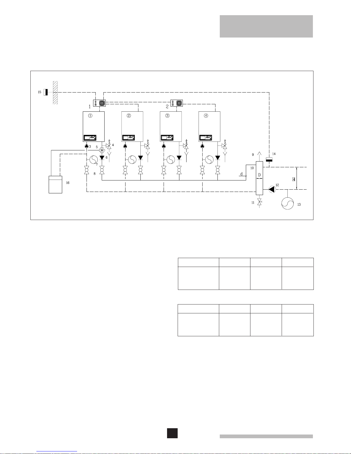
5.1.2 Installation of multiple boilers
Multiple boilers are idealy suited for use in larger commercial buildings and offer a wide variety of application
possibilities (see principle drawing).
Fig. 05 Principle drawing multiple boilers
For further advice or information refer to the Technical
Information "Multiple Units".
Contact Broag Ltd.
Table
1. rematic®4-step weather compensator (Master)
Step 1 till 4
2. rematic®4-step modular controller (Slave)
Step 5 till 8
3. Pump (to be set at position 1)
4. Safety valve
5. Three-way valve, 230 V (D.H.W.)
6. Non-return valve
7. Expansion vessel (if required)
8. Manual isolating valve
9. Automatic vent
10. Open header (neutral header)
11. Drain cock
12. Installation pump
13. Installation expansion vessel
14. Flow sensor
15. Outdoor sensor
16. D.H.W. storage
D.H.W.
No. of units
2
3
4
'D'
'd'
80
100
125
32
38
50
remeha W40-m ECO
250
250
300
H
No. of units
2
3
4
'D'
'd'
100
125
150
50
63
63
remeha W60-m ECO
300
400
500
H
9
1
2
3
4
11
12
16
18
21
23
25
26
31
33
30
29
24
6
7
8
10
5
9
15
20
22
28
27
32
35
17
19
34
14
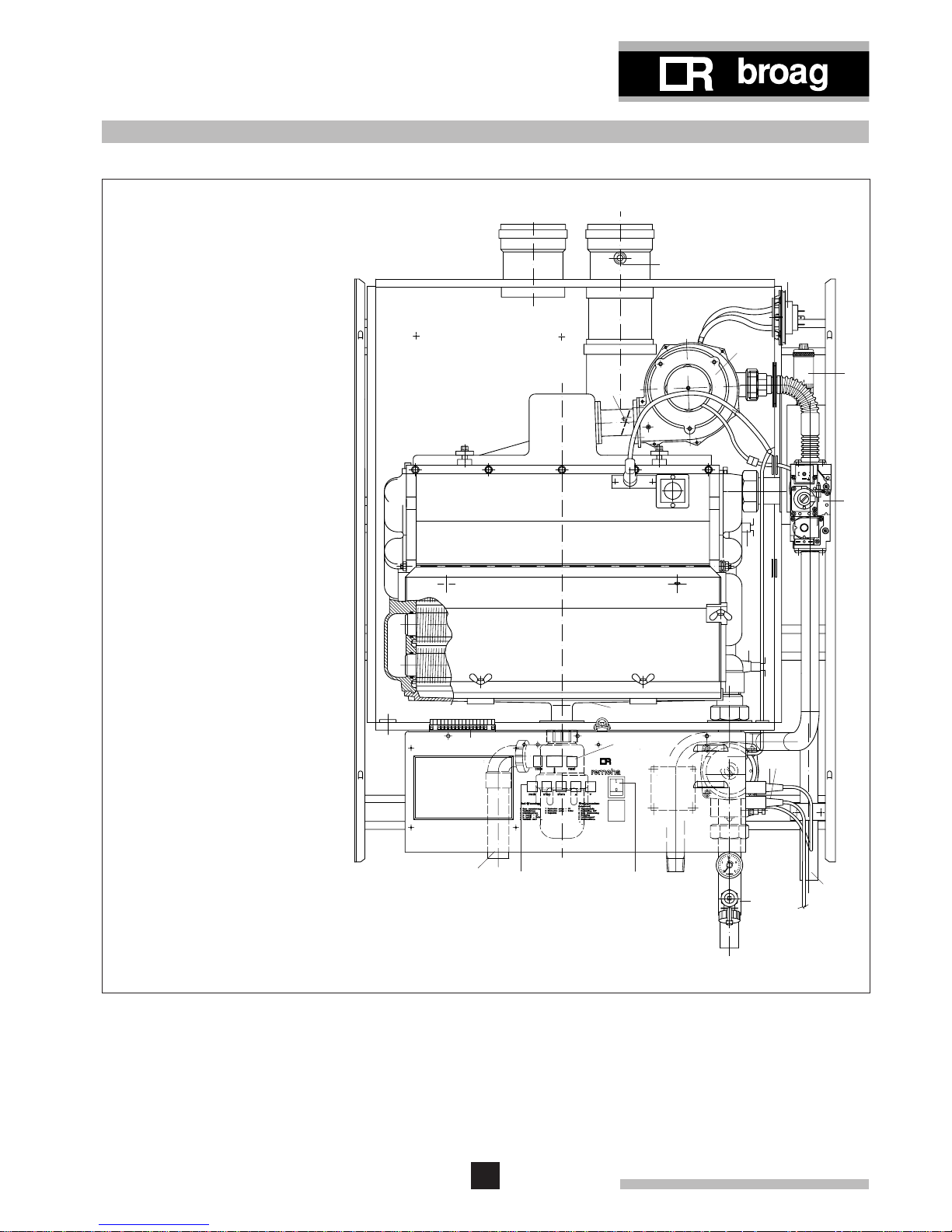
Fig. 06 Boiler layout remeha W40-m ECO
6. BOILER LAYOUT
6.1 Equipment diagram
1. Air supply
2. Flue gas discharge
3. Measure point O2 /CO
2
4. Air box
5. Slide connector
6. Differential air pressure switch
7. Spring loaded damper
8. Gas injector (behind fan)
9. Fan
10. Automatic vent
11. Burner
12. Ignition/ionisation probe
13. Sight glass
14. Manual air vent
15. Gas combi-block
16. Heat exchanger
17. Flow temperature sensor
18. Inspection cover
19. Return temperature sensor
20. Condense collector
21. Instrument panel
22. Electrical connection strip (X15)
23. Facility for incor porating a
rematic®weather compensated
boiler control
24. Condensate discharge
25. Setting keys
26. Read-out display and reset key
27. Burner switch
28. Interface for rematic®weather
compensated boiler control
29. Gas connection
30. Pump (only W40-m ECO)
31. Pressure gauge
32. Filling and drain cock
33. Return connection
34. Electrical connection pump and
three-way valve
35. Flow connection
13
10
remeha W40/60-m ECO
6.2 Operating principle
The appliance is equipped with a closed air box.Via a
fan, air is drawn in.On the intake side of the fan, an intake unit has been mounted where the gas is injected.
Depending on the settings and the ambient temperatures measured by the temperature sensors, the fan
speed is regulated.The gas/air ratio control adjusts the
quantity of gas to the quantity of air.
The gas/air mixture is achieved in the fan, and then
transported to the burner.
Following combustion, the hot flue gases are conducted
via the aluminium heat exchanger. At the heat exchanger, the flue gases give off heat to the central heating
water in the heat exchanger. The water vapour in the flue
gases condenses against the finned pipes at the base.
The heat released during this condensation process (the
so-called latent or condensation heat) is also transferred
to the central heating water.
The condensed water thus formed is discharged via a
siphon at the base of the heat exchanger.
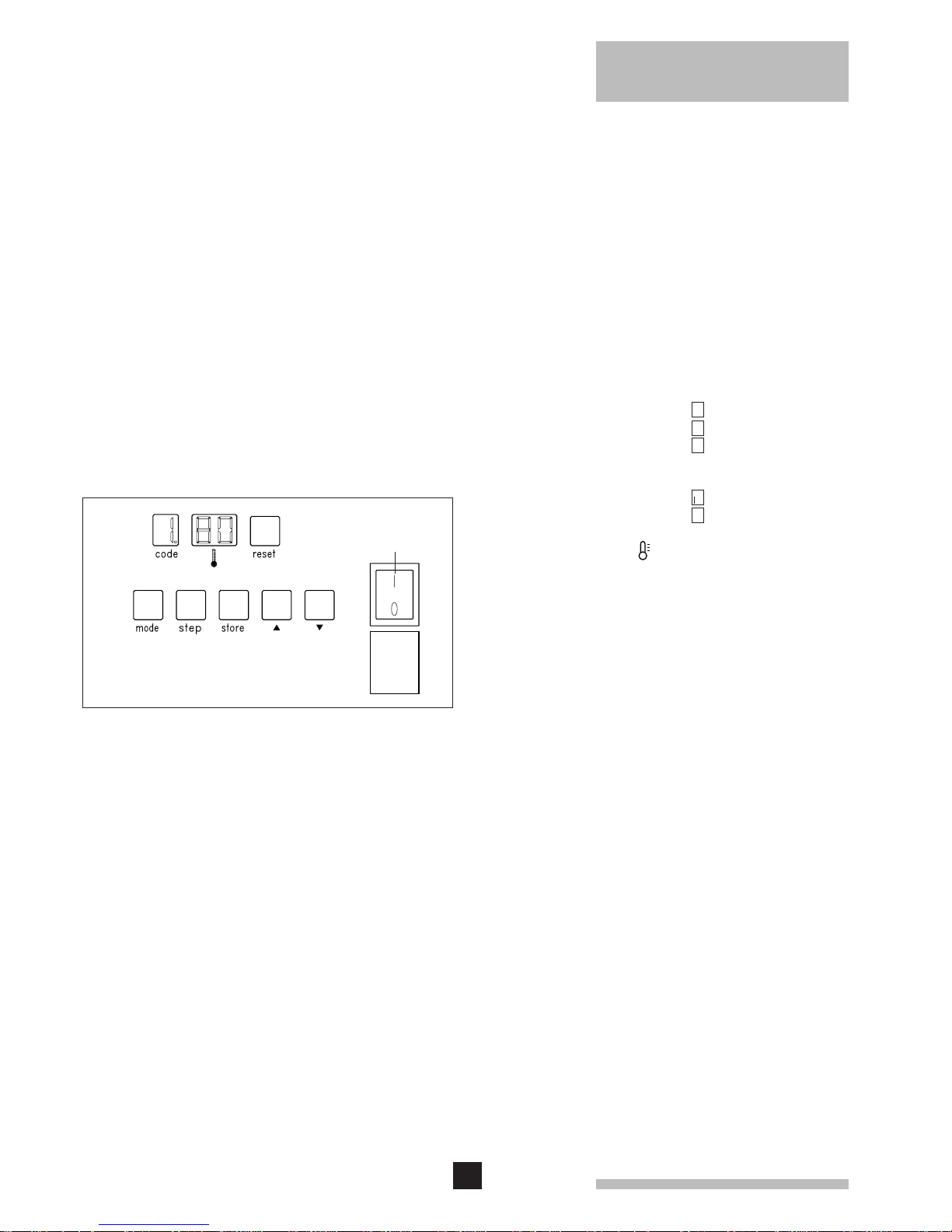
6.3 Control panel
The remeha W40/60-m ECO is equipped with an
advanced control system comprising:
a. an automatic microprocessor control system
b.a control panel with setting keys and read-out display.
Various values can be set and read, using the setting
keyboard and read-out displays.
The two levels for setting and read-out are:
- user level - free access
- service level - access by service code.
The control panel accommodates the following compo-
nents
(fig. 07)
:
a.'code'-display
display of:- operating mode 1 digit
- setting mode 1. digit and dot
- read-out mode 1. digit and blinking dot
in service level:
- speed mode half digits
- failure mode 1 blinking digit
b.temperature display ( )
display of:- temperatures
- settings
- malfunctions
c. 'reset'-key:
- to reset after a malfunction
d.'mode'-key:
- key to select the required mode
e.'step'-key:
- key to select the required program within the
selected mode
f. 'store'-key:
- key to save the settings
g.'▲'-key
- to select a higher setting
h.'▼'-key:
- to select a lower setting
i. burner switch:
- to switch the boiler on/off.
c
g h
f
ed
a
b
Fig. 07 Control panel
i
11
Fig. 08 Flow diagram microprocessor
6.4 Control system
6.4.1 General
digit and
dot
.
0-9
H,L
digit
Temperature display
'Code'-display
Press the 'step'-key
Press the 'mode'-key
1. Required flow temperature
2. Pump setting
3. D.H.W. setting
A. Boiler control operation
On service level (C 12):
6. Fan speed at full load (hundreds)
7. Fan speed at full load (units)
8. Fan speed at part load (hundreds)
9. Fan speed at part load (units)
b. D.H.W. cut-in temperature differential
C. Max. fan speed D.H.W.
d. Max. fan speed D.H.W.
E. Not applicable
F. Monitoring fan speed LD2
G. Forced par t load after star t
H. Fan speed at start
I. Max. flow temperature D.H.W.
J. D.H.W. control
L. Reser ve
n. Heating cut-in temperature differential
P. Security type
1. Flow temperature
2. Retur n temperature
3. D.H.W. temperature
4. Outdoor temperature
5. Not applicable
6. Flow temperature (setpoint)
7. Room ther mostat status and air pressure switch status
8. Reser ve
9. Not applicable
.
Fan speed
blinking
digit
1 Failure code
2 Operating mode during failure
3 Flow temperature during failure
4 Return temperature during failure
5 D.H.W. temperature during failure
6 Outdoor temperature during failure
half digits
Flow temperature
or
Operating
mode (see
para. 6.4.2)
Setting
mode (see
para. 6.4.3)
Read-out
mode (see
para. 6.4.4)
Speed
mode (see
para. 6.4.7)
Failure
mode (see
para. 6.4.8)
digit and
blinking dot
On service level (C 12):

12
remeha W40/60-m ECO
6.4.2 Operating mode
During operation the 'code'-display shows the status
(position in cycle) of the boiler, while the temperature
displays indicates the measured water temperature.
The digits in the 'code'-display have the following meaning:
0 Standby; there is no heat demand from the heating or
hot water controls.
1 Pre-purging; before start-up, the boiler is purged for
0,3 seconds.When the heat demand has been met,
the fan continues to operate for another 10 seconds.
2 Ignition: ignition is activated for 2.4 seconds while the
gas valve is opened.
3 Central heating mode; the boiler operates in the cen-
tral heating mode.
4 D.H.W. operation: the boiler operates when the three-
way valve serving the calorifier is actuated by a
demand from the D.H.W. temperature sensor.
5 Waiting mode; the fan runs and the boiler waits until
this has been proved or waits until the three-way
valve has returned to the central heating position.
7 Continued pump operation in the central heating
mode: after heat demand is met, the pump continues
to operate for the time selected (if continuous pump
operation has not been selected).
8 Continued pump operation in the D.H.W. mode; after
D.H.W. demand is met, the three-way valve will be
energized for another 5 minutes and the pump keeps
running.
9 Control stop
- flow temperature > 95˚C
- flow temperature > setpoint +5˚C
- return temperature > max. flow temp.-10˚C
- rise in flow temperature exceeded.
HForced full load.
L Forced part load.
 Loading...