

Page 1
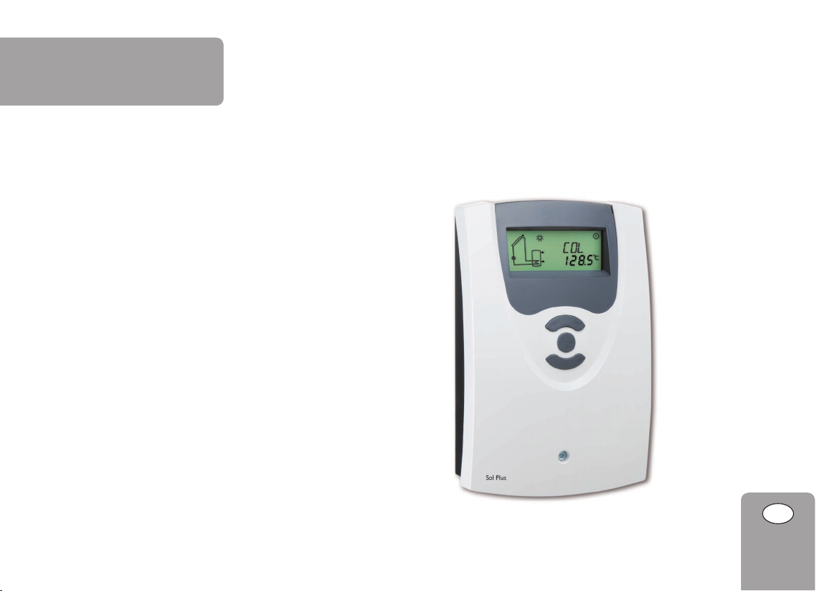
Sol Plus
Solar controller with “SOLARFIRST” function and
“STEAMBACK®” safety function
Manual for the specialised craftsman
Installation
Operation
Functions and options
Troubleshooting
*11208356*
11208356
Thank you for buying this product.
Please read this manual carefully to get the best performance from this unit.
Please keep this manual carefully.
en
Manual
Page 2
Safety advice
en
Please pay attention to the following safety advice in order to avoid danger and
damage to people and property.
Instructions
Attention must be paid to the valid local standards, regulations and directives!
Information about the product
Proper usage
The solar controller is designed for electronically controlling standard solar thermal
systems in compliance with the technical data specied in this manual.
Improper use excludes all liability claims.
CE Declaration of conformity
The product complies with the relevant directives and is therefore
labelled with the CE mark. The Declaration of Conformity is available
upon request, please contact the manufacturer.
Note
Strong electromagnetic elds can impair the function of the controller.
Î Make sure the controller as well as the system are not exposed to
strong electromagnetic elds.
Subject to technical change. Errors excepted.
Target group
These instructions are exclusively addressed to authorised skilled personnel.
Only qualied electricians should carry out electrical works.
Initial installation must be effected by the system owner or qualied personnel
named by the system owner.
Description of symbols
WARNING!
Warnings are indicated with a warning triangle!
Î They contain information on how to avoid the danger
described.
Signal words describe the danger that may occur, when it is not avoided.
• WARNING means that injury, possibly life-threatening injury, can occur
• ATTENTION means that damage to the appliance can occur
Note
Notes are indicated with an information symbol.
Î Arrows indicate instruction steps that should be carried out.
Disposal
• Dispose of the packaging in an environmentally sound manner.
• Dispose of old appliances in an environmentally sound manner. Upon request we
will take back your old appliances bought from us and guarantee an environmentally sound disposal of the devices.
© 20160621
2
Page 3

Contents
1 Overview .............................................................................................. 5
2 Installation ........................................................................................... 6
2.1 Mounting ........................................................................................................................6
2.2 Electrical connection ...................................................................................................6
2.3 PWM outputs ................................................................................................................7
2.4 Data communication / Bus .......................................................................................... 7
2.5 System overview ...........................................................................................................7
2.6 Systems ...........................................................................................................................9
3 Application examples ........................................................................ 47
4 Operation and function .................................................................... 48
4.1 Buttons ........................................................................................................................ 48
5 System-Monitoring-Display .............................................................. 48
5.1 Flashing codes ............................................................................................................ 49
6 Commissioning .................................................................................. 50
7 Channel overview .............................................................................. 52
7.1 Display channels ......................................................................................................... 52
7.2 Adjustment channels ................................................................................................ 55
8 Troubleshooting ................................................................................. 66
9 Accessories ........................................................................................ 69
9.1 Sensors and measuring instruments ..................................................................... 70
9.2 VBus
®
accessories ..................................................................................................... 70
9.3 Interface adapters ...................................................................................................... 70
10 Index ................................................................................................... 71
en
3
Page 4

Sol Plus solar controller
en
Sol Plus solar controller
The Sol Plus has been especially developed for the speed control of high-efciency
pumps in standard solar and heating systems. It is equipped with 2 PWM outputs.
Solar packages for DHW heating and heating backup with DeDietrich boilers:
The SOLAR Sol Plus with “SOLARFIRST” function (see page 47) and ModBus
controls a solar system with 1 collector eld and 1 store with integrated heat exchanger. The Sol Plus is designed for DHW heating and heating backup.
The Sol Plus controllers are equipped with the “SOLARFIRST” function via
ModBus and can be connected to DeDietrich boiler controllers by means of ModBus cables.
As soon as the solar control switches on, the system will be set to solar priority via
the connection to the boiler.
The set hot water temperature will be reduced (adjustable 0-30 K). This way, the
water will be heated by the solar system rst. If the solar system switches off, solar priority will be stopped and the controller switches the boiler to its standard
adjustments.
Due to this function, the solar system can supply 20 % more heat for the store.
The “STEAMBACK” safety concept:
The Sol Plus controller is part of the “STEAMBACK” safety concept. If the col-
lector temperature reaches 130 °C, all functions will be deactivated. The uid in
the collector continues heating and will turn into vapour at 140 °C. It will then be
pressed into the expansion vessel through extension.
The collector will not contain any solar uid then. There will be no steam hammer - the solar uid will not be harmed. If the suns goes down and if the collector
temperature falls below 140 °C, the solar uid will condense and the pressure in
the expansion vessel will ll the collector again. Only if the collector temperature
falls below 100 °C and that of the store below 60 °C, will the controller activate
the solar system.
Whether holiday, power failure or fault - the DeDietrich “STEAMBACK” safety
function protects your solar system and makes it maintenance-free and durable.
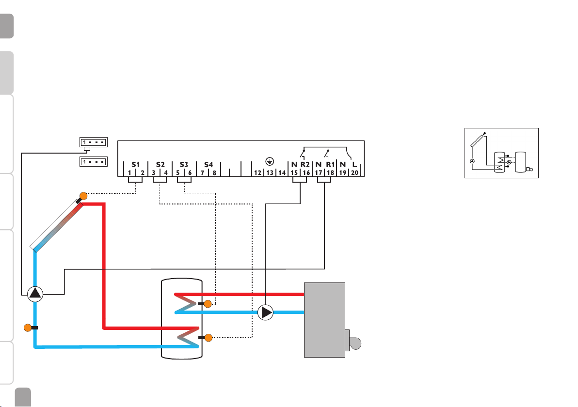
The Sol Plus solar controller is used for controlling a solar system with 1 store with
integrated heat exchanger and one 3-port valve for return preheating. It can also
control a solar system with 1 store with 2 integrated heat exchangers via a 3-port
valve. The Sol Plus is designed for DHW heating and heating backup in solar thermal
systems connected in series.
It can be directly mounted onto the pump station. For using several functions such
as store base/top or combined store with return preheating, the controller can also
control a 3-port valve in addition to the solar circuit pump. The parameter Arr can
be used for selecting the system conguration.
4
Page 5
1 Overview
• Especially designed for the speed control of high-efciency pumps
• System-Monitoring-Display
• Up to 4 Pt1000 temperature sensors
• 2 semiconductor relays for pump speed control
• HE pump control
• Heat quantity measurement
• Commissioning menu
• 10 basic systems to choose from
• Function control
• Optional thermal disinfection function
• Drainback option
• Unit °F and °C selectable
• “SOLARFIRST” function
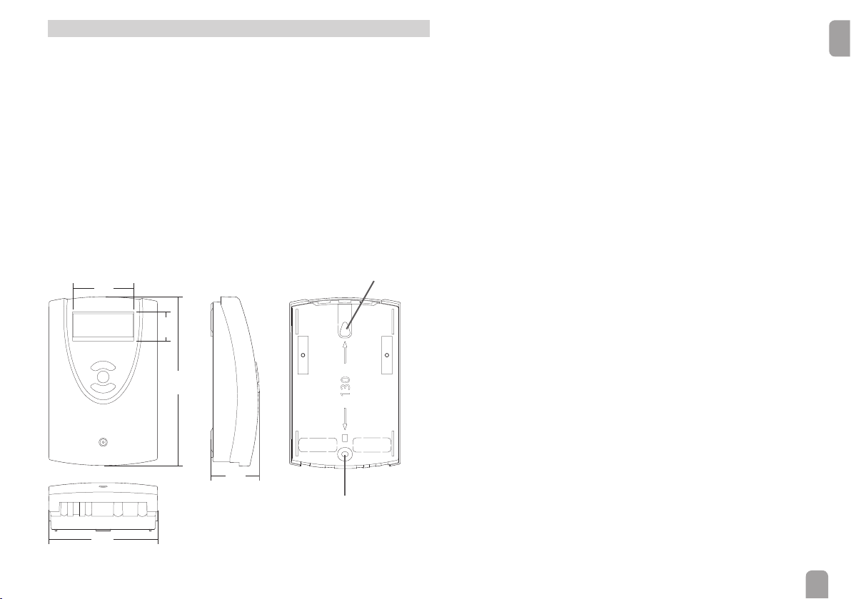
62
30
172
46
Upper fastening
130
Lower fastening
Technical data
Inputs: 4 Pt1000 temperature sensors
Outputs: 2 semiconductor relays, 2 PWM outputs
PWM frequency: 512 Hz
PWM voltage: 10.5 V
Switching capacity per relay:
R1: 1 (1) A 100 … 240 V~ (semiconductor relays)
R2: 1 (1) A 100 … 240 V~ (semiconductor relays)
Total switching capacity: 2 A 240 V~
Power supply: 100 … 240 V~, 50 … 60 Hz
Supply connection: type Y attachment
Power consumption (standby): < 1 W
Mode of operation: type 1.C.Y action
Rated impulse voltage: 2.5 kV
Data interface: VBus
®
current supply: 35 mA
VBus
®
, ModBus switching signal for the “SOLARFIRST” function
Functions: function control, operating hours counter, tube collector function,
thermostat function, speed control, drainback and booster option, heat quantity
measurement
Housing: plastic, PC-ABS and PMMA
Mounting: wall mounting, also suitable for mounting into patch panels
Indication / Display: System-Monitoring-Display for visualisation of systems,
16-segment and 7-segment display, 8 symbols for indication of system status
Operation: 3 push buttons at the front
Protection type: IP 20 / EN 60529
Protection class: I
Ambient temperature: 0 … 40 °C [32 … 104 °F]
Degree of pollution: 2
Dimensions: 172 x 110 x 46 mm
en
110
5
Page 6
en
2 Installation
2.1 Mounting
WARNING!
Installation Indications, functions and options MessagesCommissioningOperation and function
Electric shock!
Upon opening the housing, live parts are exposed!
Î Always disconnect the device from power supply
before opening the housing!
Note
Strong electromagnetic elds can impair the function of the controller.
Î Make sure the controller as well as the system are not exposed to
strong electromagnetic elds.
The unit must only be located in dry interior rooms.
The controller must additionally be supplied from a double pole switch with contact
gap of at least 3 mm.
Please pay attention to separate routing of sensor cables and mains cables.
In order to mount the device to the wall, carry out the following steps:
Î Unscrew the crosshead screw from the cover and remove it along with the
cover from the housing.
Î Mark the upper fastening point on the wall. Drill and fasten the enclosed wall
plug and screw leaving the head protruding.
Î Hang the housing from the upper fastening point and mark the lower fastening
point (centres 130 mm).
Î Insert lower wall plug.
Î Fasten the housing to the wall with the lower fastening screw and tighten.
Î Carry out the electrical wiring in accordance with the terminal allocation (see
chapter 2.2).
Î Put the cover on the housing.
Î Attach with the fastening screw.
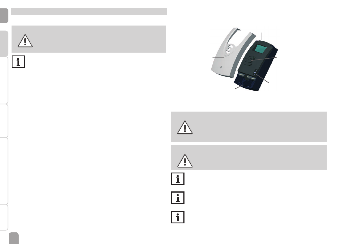
display
cover
cable conduits with
strain relief
button
fuse T4A
2.2 Electrical connection
WARNING!
ESD damage!
Electrostatic discharge can lead to damage to electronic components!
Î Take care to discharge properly before touching the
inside of the device!
WARNING!
Electric shock!
Upon opening the housing, live parts are exposed!
Î Always disconnect the device from power supply be-
fore opening the housing!
Note
The mains connection must be carried out with the common ground of
the building to which the pipework of the solar circuit is connected.
Note
Connecting the device to the power supply must always be the last step
of the installation!
Note
The pump speed must be set to 100 % when auxiliary relays or valves are
connected.
6
Page 7
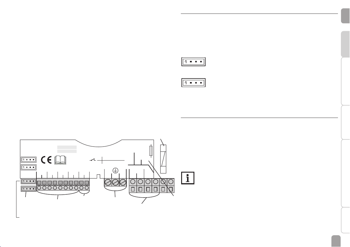
1 (1) A 240 V~
1 (1) A 240 V~
R1
R2
LN
R1
N
2019
18
171615
14131212
NR2
T2A
100 ... 240 V~
50-60 Hz
Temp. Sensor Pt1000
S2S1 S3 S4 VBus
PWM 1/2
ModBus
345678910
F-67580 Mertzwiller
DDTh
Sol Plus
Article/Artikel 7630422
Soft version 2.00
Serial number
IP 20
The power supply of the device must be 100 … 240 V~ (50 … 60 Hz). Attach exible
1 (1) A 240 V~
1 (1) A 240 V~
R1
LN
R1
T2A
100 ... 240 V~
50-60 Hz
F-67580 Mertzwiller
DDTh
Sol Plus
Article/Artikel 7630422
Soft version 2.00
Serial number
IP 20
1 (1) A 240 V~
1 (1) A 240 V~
R1
R2
LN
R1
N
2019
18
NR2
T2A
100 ... 240 V~
50-60 Hz
Temp. Sensor Pt1000
S2S1 S3 S4 VBus
PWM 1/2
ModBus
F-67580 Mertzwiller
DDTh
Sol Plus
Article/Artikel 7630422
Soft version 2.00
Serial number
IP 20
cables to the housing with the enclosed strain relief and the corresponding screws.
The controller is equipped with 2 semiconductor relays to which loads such as
pumps, valves, etc. can be connected:
Relay 1 Relay 2
18 = Conductor R1 16 = Conductor R2
17 = Neutral conductor N 15 = Neutral conductor N
13 = Protective earth conductorr ⏚ 14 = Protective earth conductorr ⏚
The mains connection is at the following terminals:
19 = Neutral conductor N
20 = Conductor L
12 = Protective earth conductor ⏚
Connect the temperature sensors (S1 to S4) to the corresponding terminals
with either polarity:
1 / 2 = Sensor 1 (e. g. collector sensor 1)
3 / 4 = Sensor 2 (e. g. store sensor 1)
5 / 6 = Sensor 3 (e. g. store sensor top)
7 / 8 = Sensor 4 (e. g. return sensor)
Fuse
2.3 PWM outputs
Speed control of a HE pump is possible via a PWM signal. The pump has to be connected to the relay as well as to one of the PWM outputs of the controller. Power
is supplied to the HE pump by switching the corresponding relay on or off.
The terminals marked PWM 1 / 2 are control outputs for pumps with PWM control input.
PWM 1/2
1 = PWM output 1, control signal
2 = PWM output 1, GND
3 = PWM output 2, GND
2 4
1 3
4 = PWM output 2, control signal
1 = ModBus A
2 = GND
3 = free
2 4
1 3
4 = ModBus B
ModBus = Optional (for connection to the boiler (if provided by the boiler))
2.4 Data communication / Bus
®
The controller is equipped with the VBus
for data transfer and energy supply
to external modules. The connection is to be carried out at the terminals marked
VBus (either polarity).
One or more VBus
®
modules can be connected via this data bus, such as:
• DL2 Datalogger
• DL3 Datalogger
Furthermore, the controller can be connected to a PC or integrated into a network
via the VBus
®
/USB or VBus®/LAN interface adapter (not included).
Note
More accessories on page 69.
en
InstallationIndications, functions and optionsMessages Commissioning Operation and function
ModBus
connection
PWM
connection
®
VBus
sensor terminals
protective earth
conductor terminal
load terminals
mains
terminals
7
Page 8
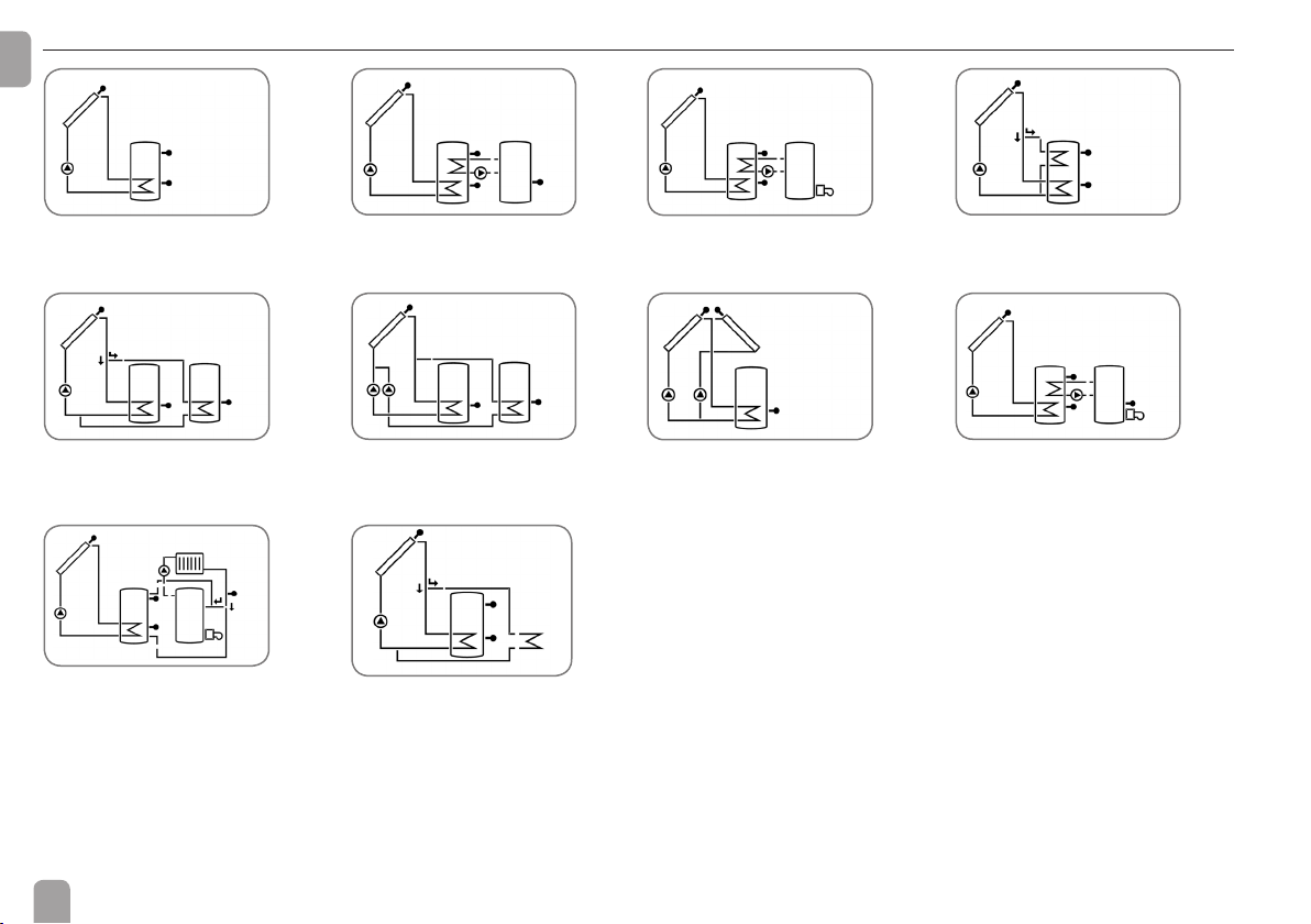
2.5 System overview
en
1
Standard solar system (page 9)
5
Solar system with 2 stores and valve
logic (page 26)
9
Solar system with heating circuit
return preheating (page 41)
2
Solar system with heat exchange
(page 12)
6
Solar system with 2 stores and pump
logic (page 29)
10
Standard solar system with heat dump
(page 44)
3
Solar system with backup heating
(page 18)
7
Solar system with east-/west collectors
and 1 store (page 32)
4
Solar system with store loading in
layers (page 23)
8
Solar system with backup heating by
solid fuel boiler (page 35)
8
Page 9
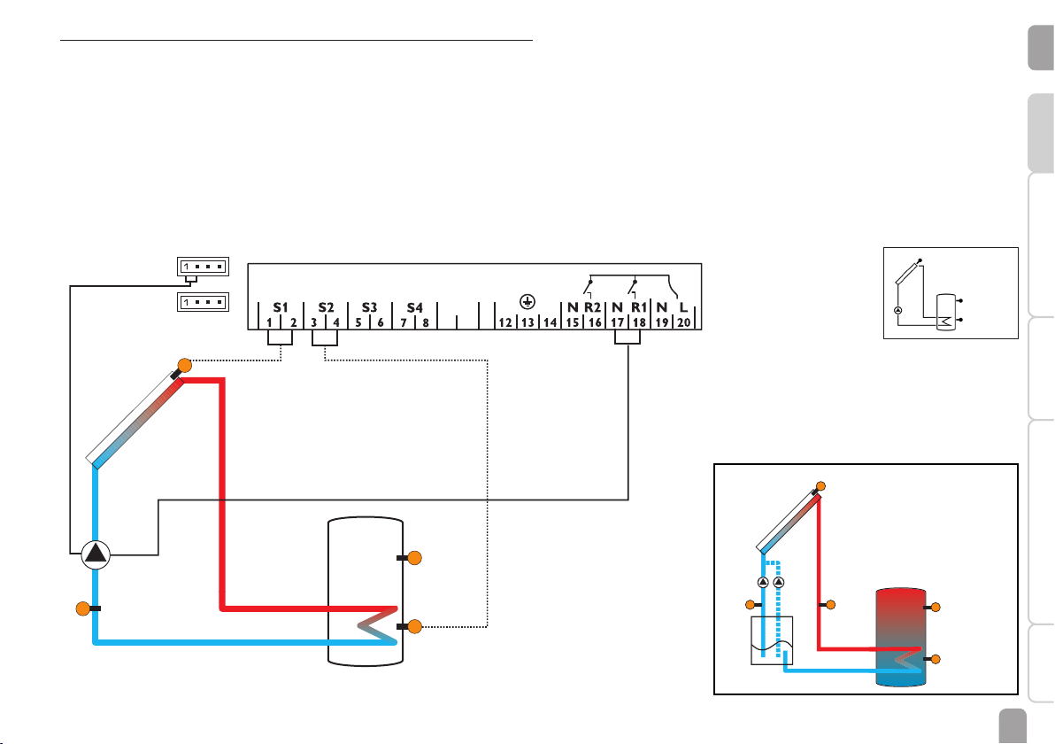
2.6 Systems
9
10
VBus
PWM 1/2
ModBus
Arrangement 1: Standard solar system
The controller calculates the temperature difference between collector sensor S1
and store sensor S2. If the difference is larger than or identical to the adjusted
switch-on temperature difference (DT O), the solar pump will be activated by relay
1, and the store will be loaded until the switch-off temperature difference (DT F) or
the maximum store temperature (S MX) is reached.
S1
Sensors S3 and S4 can optionally be connected. S3 can optionally be used as the
reference sensor for the store emergency shutdown option (OSEM).
If heat quantity measurement (OHQM) is activated, S4 is used as the return sensor.
If the drainback option (ODB) is activated, relay 2 can be used for activating a
booster pump. For this purpose, the booster function (OBST) has to be activated.
en
InstallationIndications, functions and optionsMessages Commissioning Operation and function
R1
S4 / TR
S3 / TSTT
S2
R1 R2
S1
drainback system layout
(with booster pump)
exemplary
S3
S2
9
Page 10

Display channels
en
Channel Description Connection terminal Page
INIT x* ODB initialisation active - 52
FLL x* ODB lling time active - 52
Installation Indications, functions and options MessagesCommissioningOperation and function
STAB x* ODB stabilisation in progress - 52
COL x Temperature collector S1 53
TST x Temperature store S2 53
S3 x Temperature sensor 3 S3 53
TSTT x* Temperature store top S3 53
S4 x Temperature sensor 4 S4 53
n % x Speed R1 R1 54
hP x Operating hours R1 R1 55
hP1 x* Operating hours R1 (if OBST is activated) R1 55
hP2 x* Operating hours R2 (if OBST is activated) R2 55
kWh x* Heat quantity in kWh - 54
MWh x* Heat quantity in MWh - 54
TIME x Time - 55
Adjustment channels
Channel Description Factory setting Page
Arr x System 1 55
DT O x Switch-on temperature difference R1 6.0 K [12.0 °Ra] 56
DT F x Switch-off temperature difference R1 4.0 K [8.0 °Ra] 56
DT S x Set temperature difference R1 10.0 K [20.0 °Ra] 56
RIS x Rise R1 2 K [4 °Ra] 56
PUM1 x Pump control type R1 PSOL 56
nMN x Minimum speed R1 30 % 57
nMX x Maximum speed R1 100 % 57
S MX x Maximum store temperature 75 °C [167 °F] 57
OSEM x Store emergency shutdown option OFF 57
EM x
OCC x Collector cooling option OFF 58
CMX x* Maximum collector temperature 110 °C [230 °F] 58
OSYC x System cooling option OFF 59
Collector emergency temperature 130 °C [270 °F] 58
Collector emergency temperature if ODB is activated: 95 °C [200 °F] 58
10
Page 11

Adjustment channels
Channel Description Factory setting Page
DTCO x* Switch-on temperature difference cooling 20.0 K [40.0 °Ra] 59
DTCF x* Switch-off temperature difference cooling 15.0 K [30.0 °Ra] 59
OSTC x Store cooling option OFF 59
OHOL x* Holiday cooling option OFF 59
THOL x* Holiday cooling temperature 40 °C [110 °F] 59
OCN x Collector minimum limitation option OFF 60
CMN x* Collector minimum temperature 10 °C [50 °F] 60
OCF x Antifreeze option OFF 60
CFR x* Antifreeze temperature 4.0 °C [40.0 °F] 60
OTC x Tube collector option OFF 62
TCST x* OTC starting time 07:00 62
TCEN x* OTC ending time 19:00 62
TCRU x* OTC runtime 30 s 62
TCIN x* OTC standstill interval 30 min 62
OHQM x Heat quantity measurement option OFF 62
FMAX x* Maximum ow rate 6.0 l/min 63
MEDT x* Antifreeze type 1 63
MED% x* Antifreeze concentration (only if MEDT = propylene or ethylene glycol) 45 % 63
ODB x Drainback option OFF 63
tDTO x* ODB switch-on condition - time period 60 s 64
tFLL x* ODB lling time 5.0 min 64
tSTB x* ODB stabilisation time 2.0 min 64
OBST s* Option booster function OFF 64
MAN1 x Manual mode R1 Auto 64
MAN2 x Manual mode R2 Auto 64
MB x ModBus slave address 60 65
LANG x Language dE 65
UNIT x Temperature unit °C 65
RESE x Reset - back to factory settings 65
######## Version number
en
InstallationIndications, functions and optionsMessages Commissioning Operation and function
Legend:
Symbol Description
x Channel is available
x* Channel is available, if the corresponding option is activated.
s* System-specic channel, only available if the corresponding option is activated
11
Page 12
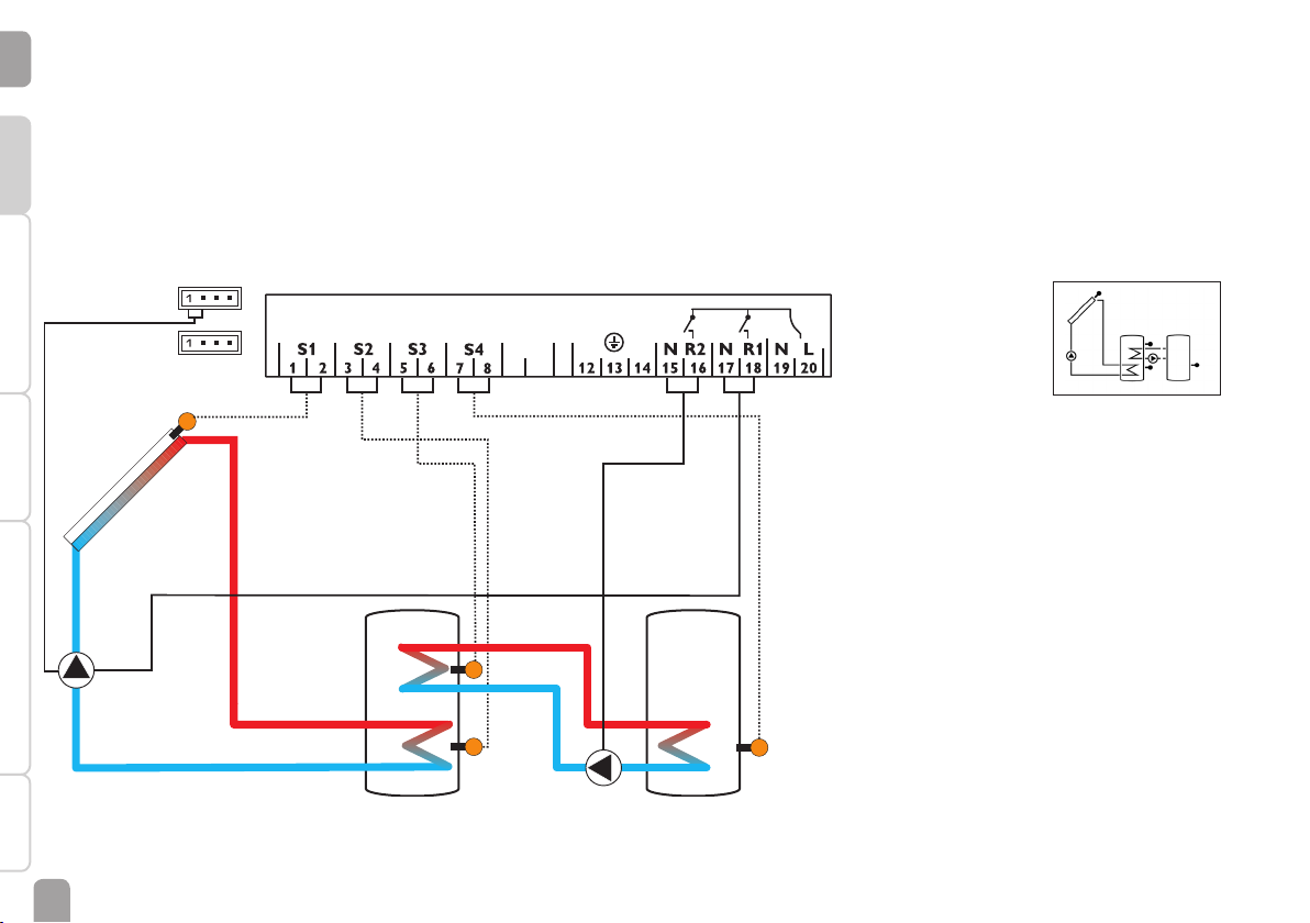
Arrangement 2: Solar system with heat exchange
9
10
VBus
PWM 1/2
ModBus
en
The controller calculates the temperature difference between collector sensor S1
and store sensor S2. If the difference is larger than or identical to the adjusted
switch-on temperature difference (DT O), the solar pump will be activated by relay
Installation Indications, functions and options MessagesCommissioningOperation and function
1, and the store will be loaded until the switch-off temperature difference (DT F) or
the maximum store temperature (S MX) is reached.
S1
Heat exchange from store 1 to store 2 will be operated by relay 2, if the temperature difference between sensors S3 and S4 is larger than or identical to the adjusted
switch-on temperature difference (DT3O), until the adjusted minimum (MN3O)
and maximum (MX3O) temperature thresholds of the respective store are reached.
S3 can optionally be used as the reference sensor for the store emergency shutdown option (OSEM).
Store 1 Store 2
R1
S3 / TSTT
S2
S4
R2
12
Page 13

Display channels
Channel Description Connection terminal Page
INIT x* ODB initialisation active - 52
FLL x* ODB lling time active - 52
STAB x* ODB stabilisation in progress - 52
COL x Temperature collector S1 53
TST1 x Temperature store 1 base S2 53
TSTT x Temperature store 1 top S3 53
TST2 x Temperature store 2 base S4 53
n1 % x Speed R1 R1 54
n2 % x Speed R2 R2 54
h P1 x Operating hours R1 R1 55
h P2 x Operating hours R2 R2 55
kWh x* Heat quantity in kWh - 54
MWh x* Heat quantity in MWh - 54
TIME x Time - 55
Adjustment channels
Channel Description Factory setting Page
Arr x System 2 55
DT O x Switch-on temperature difference R1 6.0 K [12.0 °Ra] 56
DT F x Switch-off temperature difference R1 4.0 K [8.0 °Ra] 56
DT S x Set temperature difference R1 10.0 K [20.0 °Ra] 56
RIS x Rise R1 2 K [4 °Ra] 56
PUM1 x Pump control type R1 PSOL 56
n1MN x Minimum speed R1 30 % 57
n1MX x Maximum speed R1 100 % 57
S MX x Maximum store temperature 75 °C [167 °F] 57
OSEM x Store emergency shutdown option OFF 57
PUM2 x Pump control type R2 OnOF 56
n2MN x* Minimum speed R2 30 % 57
n2MX x* Maximum speed R2 100 % 57
EM x
OCC x Collector cooling option OFF 58
CMX x* Maximum collector temperature 110 °C [230 °F] 58
OSYC x System cooling option OFF 59
DTCO x* Switch-on temperature difference cooling 20.0 K [40.0 °Ra] 59
DTCF x* Switch-off temperature difference cooling 15.0 K [30.0 °Ra] 59
OSTC x Store cooling option OFF 59
OHOL x* Holiday cooling option OFF 59
Collector emergency temperature 130 °C [270 °F] 58
Collector emergency temperature if ODB is activated: 95 °C [200 °F] 58
en
InstallationIndications, functions and optionsMessages Commissioning Operation and function
13
Page 14

Adjustment channels
en
Channel Description Factory setting Page
THOL x* Holiday cooling temperature 40 °C [110 °F] 59
OCN x Collector minimum limitation option OFF 60
CMN x* Collector minimum temperature 10 °C [50 °F] 60
Installation Indications, functions and options MessagesCommissioningOperation and function
OCF x Antifreeze option OFF 60
CFR x* Antifreeze temperature 4.0 °C [40.0 °F] 60
OTC x Tube collector option OFF 62
TCST x* OTC starting time 07:00 62
TCEN x* OTC ending time 19:00 62
TCRU x* OTC runtime 30 s 62
TCIN x* OTC standstill interval 30 min 62
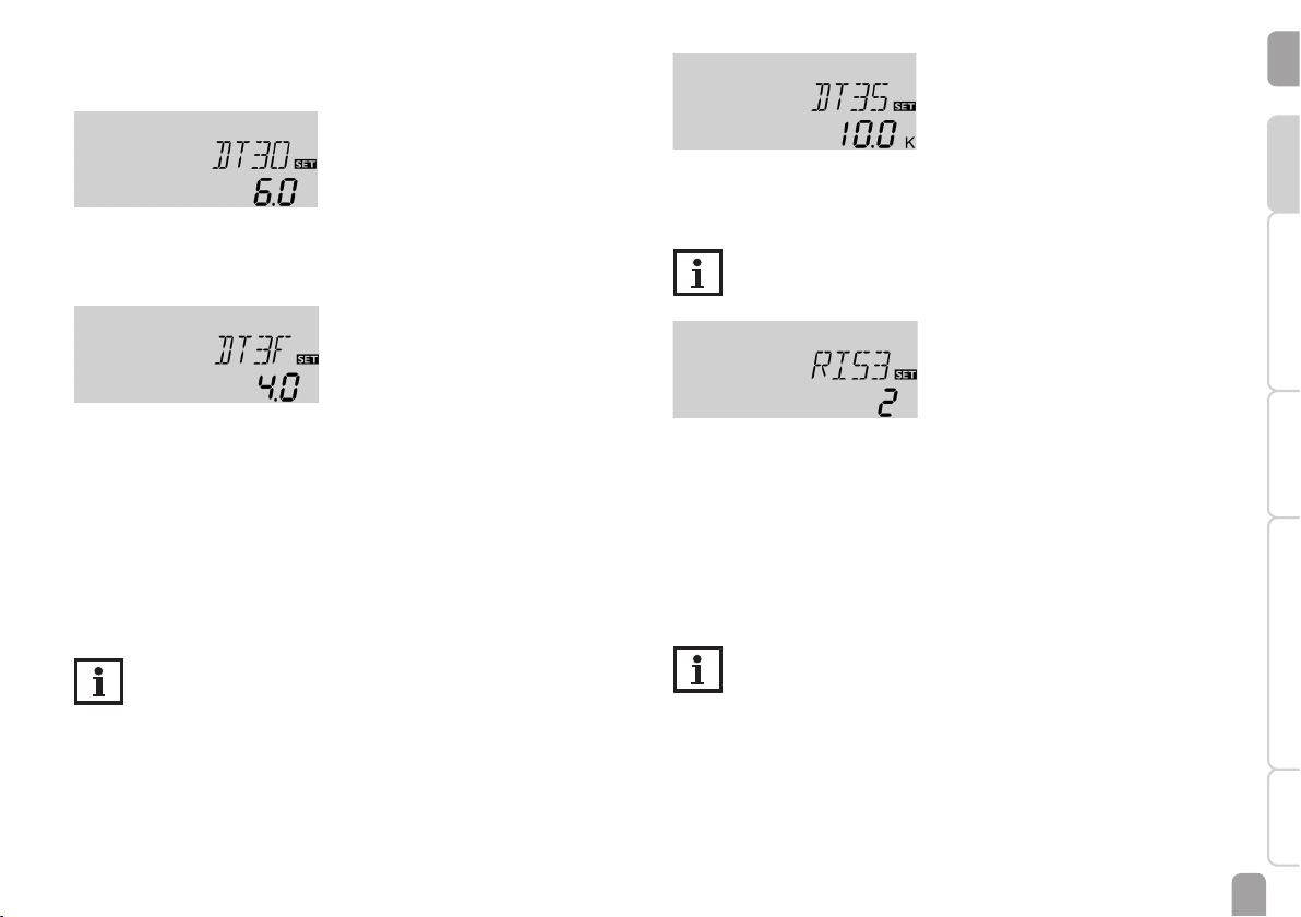
DT3O s Switch-on temperature difference R2 6.0 K [12.0 °Ra] 56
DT3F s Switch-off temperature difference R2 4.0 K [8.0 °Ra] 56
DT3S s Set temperature difference R2 10.0 K [20.0 °Ra] 56
RIS3 s Rise R2 2 K [4 °Ra] 56
MX3O s Switch-on threshold for maximum temperature 60.0 °C [140.0 °F] 40
MX3F s Switch-off threshold for maximum temperature 58.0 °C [136.0 °F] 40
MN3O s Switch-on threshold for minimum temperature 5.0 °C [40.0 °F] 40
MN3F s Switch-off threshold for minimum temperature 10.0 °C [50.0 °F] 40
ODB x Drainback option OFF 63
tDTO x* ODB switch-on condition - time period 60 s 64
tFLL x* ODB lling time 5.0 min 64
tSTB x* ODB stabilisation time 2.0 min 64
MAN1 x Manual mode R1 Auto 64
MAN2 x Manual mode R2 Auto 64
MB x ModBus slave address 60 65
LANG x Language dE 65
UNIT x Temperature unit °C 65
RESE x Reset - back to factory settings 65
######## Version number
Legend:
Symbol Description
x Channel is available
x* Channel is available, if the corresponding option is activated.
s System-specic channel
14
Page 15
System-specic functions
The following adjustments are used for the specic functions in system 2.
∆T control for the heat exchange between 2 stores
DT3O
Switch-on temperature difference
Adjustment range: 1.0 … 20.0 K [2.0 … 40.0°Ra]
Factory setting: 6.0 K [12.0 °Ra]
Speed control
DT3S
Set temperature difference
Adjustment range: 1.5 … 30.0 K [3.0 … 60.0 °Ra]
Factory setting: 10.0 K [20.0 °Ra]
Note
For pump speed control of the heat exchange pump, the operating mode
of relay 2 must be set to Auto in the adjustment channel MAN2.
en
InstallationIndications, functions and optionsMessages Commissioning Operation and function
DT3F
Switch-off temperature difference
Adjustment range: 0.5 … 19.5 K [1.0 … 39.0°Ra]
Factory setting: 4.0 K [8.0 °Ra]
S3 and S4 are used as the reference sensors for this function.
In system 2 the controller is equipped with an additional differential control for heat
exchange between two stores. The basic differential function is adjusted using the
switch-on (DT3O) and switch-off (DT3F) temperature differences.
When the temperature difference exceeds the adjusted switch-on temperature
difference, relay 2 switches on. When the temperature difference falls below the
adjusted switch-off temperature difference, relay 2 switches off.
Note
The switch-on temperature difference must be at least 0.5 K [1 °Ra] higher than the switch-off temperature difference.
RIS3
Rise
Adjustment range: 1 … 20 K [2 … 40 °Ra]
Factory setting: 2 K [4 °Ra]
If the switch-on difference is reached, the pump switches on at full speed for 10 s.
Then, the speed is reduced to the minimum pump speed value (n2MN).
If the temperature difference reaches the adjusted set value (DT3S), the pump
speed increases by one step (10 %). Each time the difference increases by the adjustable rise value RIS3, the pump speed increases by 10 % until the maximum pump
speed of 100% is reached.
Note
The set temperature difference must be at least 0.5 K [1 °Ra] higher than
the switch-on temperature difference.
15
Page 16
en
Installation Indications, functions and options MessagesCommissioningOperation and function
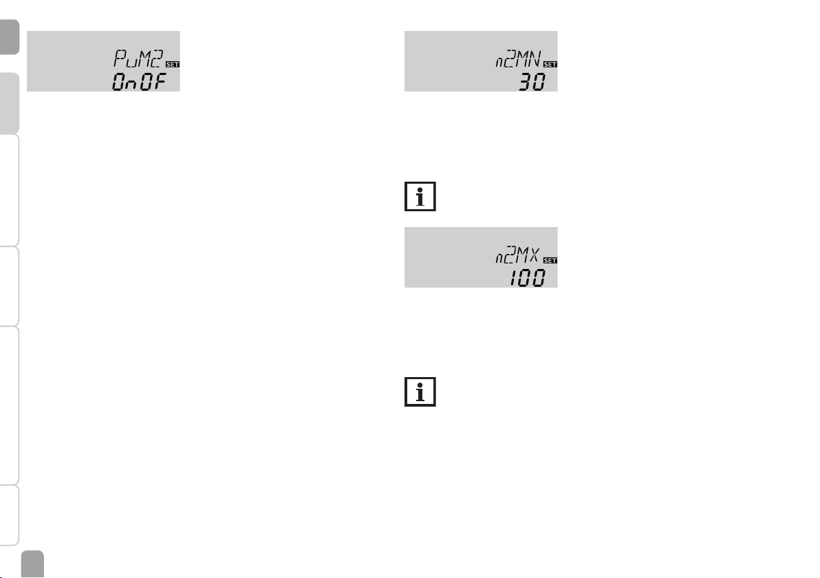
PUM2
Pump control type R2
Selection: OnOF, PULS, PSOL, PHEA
Factory setting: OnOF
With this parameter, the pump control type can be adjusted. The following types
can be selected:
Adjustment for standard pump without speed control
• OnOF (pump on / pump off)
Adjustment for standard pump with speed control
• PULS (burst control via semiconductor relay)
Adjustment for high-efciency pump (HE pump)
• PSOL (PWM prole for a HE solar pump)
• PHEA (PWM prole for a HE heating pump)
n2MN
Minimum speed R2
Adjustment range: (10) 30 … 100 %
Factory setting: 30 %
A relative minimum pump speed can be allocated to the output R2 via the adjustment channel n2MN.
Note
The pump speed must be set to 100 % when auxiliary relays or valves are
connected.
n2MX
Maximum speed R2
Adjustment range: (10) 30 … 100 %
Factory setting: 100 %
In the adjustment channel n2MX a relative maximum speed for a pump connected
can be allocated to the output R2.
Note
The pump speed must be set to 100 % when auxiliary relays or valves are
connected.
16
Page 17
Maximum temperature limitation heat exchange
Minimum temperature limitation heat exchange
en
InstallationIndications, functions and optionsMessages Commissioning Operation and function
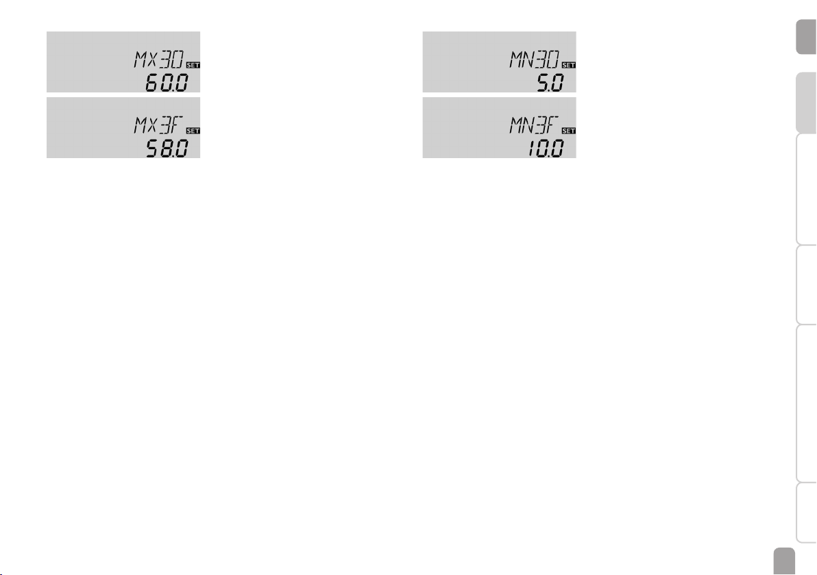
MX3O / MX3F
Maximum temperature limitation
Adjustment range: 0.0 … 95.0 °C [30.0 … 200.0 °F]
Factory setting:
MX3O: 60.0 °C [140.0 °F]
MX3F: 58.0 °C [136.0 °F]
S4 is used as the reference sensor for the maximum temperature limitation.
The maximum temperature limitation function provides a maximum temperature
setting, usually to reduce scald risk in a store. If MX3O is exceeded, relay 2 is
switched off until the temperature at sensor 4 falls below MX3F.
MN3O / MN3F
Minimum temperature limitation
Adjustment range: 0.0 … 90.0 °C [30.0 … 190.0 °F]
Factory setting (only if Arr = 2):
MN3O: 5.0 °C [40.0 °F]
MN3F: 10.0 °C [50.0 °F]
S3 is used as the reference sensor for the minimum temperature limitation.
The minimum temperature limitation function provides a minimum temperature
setting for the heat source in system 2. If the temperature at sensor 3 falls below
MN3O, relay 2 is switched off until the temperature at sensor 3 exceeds MN3F.
Both switch-on and switch-off temperature differences DT3O and DT3F are valid
for the maximum and minimum temperature limitation.
17
Page 18
Arrangement 3: Solar system with backup heating
en
The controller calculates the temperature difference between collector sensor S1
and store sensor S2. If the difference is larger than or identical to the adjusted
switch-on temperature difference (DT O), the solar pump will be activated by relay
Installation Indications, functions and options MessagesCommissioningOperation and function
1, and the store will be loaded until the switch-off temperature difference (DT F) or
the maximum store temperature (S MX) is reached.
Sensor S3 is used for a thermostat function, which operates relay 2 for backup
heating or heat dump purposes, when the adjusted thermostat switch-on temperature (AH O) is reached. This function can optionally be combined with up to three
adjustable time frames.
PWM 1/2
Sensor S3 can optionally be used as the reference sensor for the thermal disinfection function (OTD) or the store emergency shutdown option (OSEM).
Sensor S4 can optionally be connected. If heat quantity measurement (OHQM) is
activated, S4 is used as the return sensor.
ModBus
VBus
10
9
S1
R1
S3 / TSTT
S4 / TR
18
S2
R2
Page 19

Display channels
Channel Description Connection terminal Page
INIT x* ODB initialisation active - 52
FLL x* ODB lling time active - 52
STAB x* ODB stabilisation in progress - 52
COL x Temperature collector S1 53
TSTB x Temperature store 1 base S2 53
TSTT x Temperature store 1 top S3 53
TDIS s* Thermal disinfection temperature (thermal disinfection) S3 53
S4 x Temperature sensor 4 S4 53
n1 % x Speed R1 R1 54
h P1 x Operating hours R1 R1 55
h P2 x Operating hours R2 R2 55
kWh x* Heat quantity in kWh - 54
MWh x* Heat quantity in MWh - 54
CDIS s* Countdown of monitoring period (thermal disinfection) - 54
SDIS s* Starting time display (thermal disinfection) - 54
DDIS s* Heating period display (thermal disinfection) - 54
TIME x Time - 55
Adjustment channels
Channel Description Factory setting Page
Arr x System 3 55
DT O x Switch-on temperature difference R1 6.0 K [12.0 °Ra] 56
DT F x Switch-off temperature difference R1 4.0 K [8.0 °Ra] 56
DT S x Set temperature difference R1 10.0 K [20.0 °Ra] 56
RIS x Rise R1 2 K [4 °Ra] 56
PUM1 x Pump control type R1 PSOL 56
n1MN x Minimum speed R1 30 % 57
n1MX x Maximum speed R1 100 % 57
S MX x Maximum store temperature 75 °C [167 °F] 57
OSEM x Store emergency shutdown option OFF 57
EM x
OCC x Collector cooling option OFF 58
CMX x* Maximum collector temperature 110 °C [230 °F] 58
OSYC x System cooling option OFF 59
DTCO x* Switch-on temperature difference cooling 20.0 K [40.0 °Ra] 59
DTCF x* Switch-off temperature difference cooling 15.0 K [30.0 °Ra] 59
OSTC x Store cooling option OFF 59
OHOL x* Holiday cooling option OFF 59
THOL x* Holiday cooling temperature 40 °C [110 °F] 59
OCN x Collector minimum limitation option OFF 60
Collector emergency temperature 130 °C [270 °F] 58
Collector emergency temperature if ODB is activated: 95 °C [200 °F] 58
en
InstallationIndications, functions and optionsMessages Commissioning Operation and function
19
Page 20

Adjustment channels
en
Channel Description Factory setting Page
CMN x* Collector minimum temperature 10 °C [50 °F] 60
OCF x Antifreeze option OFF 60
CFR x* Antifreeze temperature 4.0 °C [40.0 °F] 60
Installation Indications, functions and options MessagesCommissioningOperation and function
OTC x Tube collector option OFF 62
TCST x* OTC starting time 07:00 62
TCEN x* OTC ending time 19:00 62
TCRU x* OTC runtime 30 s 62
TCIN x* OTC standstill interval 30 min 62
OHQM x Heat quantity measurement option OFF 62
FMAX x* Maximum ow rate 6.0 l/min 63
MEDT x* Antifreeze type 1 63
MED% x* Antifreeze concentration 45 % 63
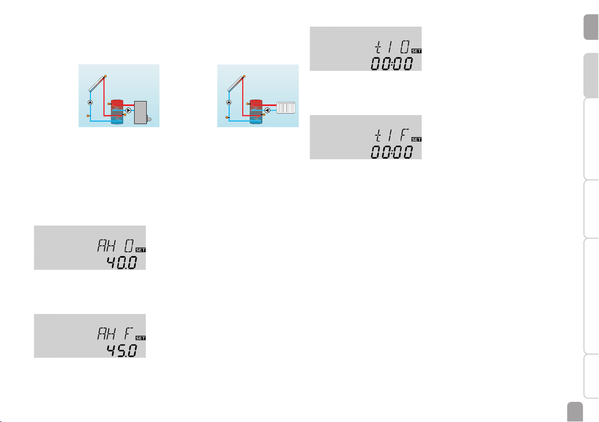
AH O s Switch-on temperature for thermostat 40 °C [110 °F] 21
AH F s Switch-off temperature for thermostat 45 °C [120 °F] 21
t1 O s Thermostat switch-on time 1 00:00 21
t1 F s Thermostat switch-off time 1 00:00 21
t2 O s Thermostat switch-on time 2 00:00 21
t2 F s Thermostat switch-off time 2 00:00 21
t3 O s Thermostat switch-on time 3 00:00 21
t3 F s Thermostat switch-off time 3 00:00 21
ODB x Drainback option OFF 63
tDTO x* ODB switch-on condition - time period 60 s 64
tFLL x* ODB lling time 5.0 min 64
tSTB x* ODB stabilisation time 2.0 min 64
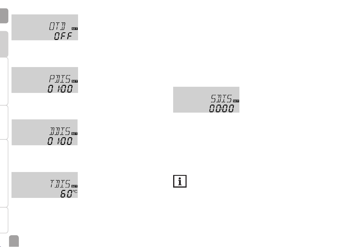
OTD s Thermal disinfection option OFF 22
PDIS s* Monitoring period 01:00 22
DDIS s* Heating period 01:00 22
TDIS s* Disinfection temperature 60 °C [140 °F] 22
SDIS s* Starting time 00:00 22
MAN1 x Manual mode R1 Auto 64
MAN2 x Manual mode R2 Auto 64
MB x ModBus slave address 60 65
LANG x Language dE 65
UNIT x Temperature unit °C 65
RESE x Reset - back to factory settings 65
######## Version number
Legend:
Symbol Description
x Channel is available
x* Channel is available, if the corresponding option is activated.
s System-specic channel
s* System-specic channel, only available if the corresponding option is activated
20
Page 21
System-specic functions
The following adjustments are used for the specic functions in system 3. The channels described are not available in any other systems.
Thermostat function
Backup heating
Use of surplus
energy
The thermostat function works independently from the solar operation and can be
used for using surplus energy or for backup heating.
• AH O < AH F
thermostat function for backup heating
• AH O > AH F
thermostat function for using surplus energy
The symbol ⓶ will be shown on the display, if the second relay output is activated.
S3 is used as the reference sensor for the thermostat function.
AH O
Thermostat switch-on temperature
Adjustment range: 0.0 … 95.0 °C [30.0 … 200.0 °F]
Factory setting: 40.0 °C [110.0°F]
t1 O, t2 O, t3 O
Thermostat switch-on time
Adjustment range: 00:00 … 23:45
Factory setting: 00:00
t1 F, t2 F, t3 F
Thermostat switch-off time
Adjustment range: 00:00 … 23:45
Factory setting: 00:00
In order to block the thermostat function for a certain period, there are 3 time
frames t1 … t3.
If the thermostat function is supposed to run from 06:00 a.m. to 09:00 a.m. only,
adjust t1 O to 06:00 a.m. and t1 F to 09:00 a.m.
If the switch-on and switch-off times of a time frame are set to an identical value,
the time frame will be inactive. If all time frames are set to 00:00, the thermostat
function is solely temperature dependent (factory setting).
en
InstallationIndications, functions and optionsMessages Commissioning Operation and function
AH F
Thermostat switch-off temperature
Adjustment range: 0.0 … 95.0 °C [30.0 … 200.0 °F]
Factory setting: 45.0 °C [120.0 °F]
21
Page 22
Thermal disinfection of the upper DHW zone
en
Installation Indications, functions and options MessagesCommissioningOperation and function
OTD
Therm. disinfection function
Adjustment range: OFF / ON
Factory setting: OFF
PDIS
Monitoring period
Adjustment range: 0 … 30:0 … 24 h (dd:hh)
Factory setting: 01:00
DDIS
Heating period
Adjustment range: 0:00 … 23:59 (hh:mm)
Factory setting: 01:00
This function helps to contain the spread of Legionella in DHW stores by systematically activating the backup heating.
For thermal disinfection, the temperature at the reference sensor will be monitored. Protection is ensured when, during the monitoring period, the disinfection
temperature is continuously exceeded for the entire disinfection period.
The monitoring period starts as soon as the temperature at the reference sensor
falls below the disinfection temperature. When the monitoring period ends, the
allocated reference relay activates the backup heating. The disinfection period starts,
if the temperature at the allocated sensor exceeds the disinfection temperature.
Thermal disinfection can only be completed when the disinfection temperature
is exceeded for the duration of the disinfection period without any interruption.
Starting time delay
SDIS
Starting time
Adjustment range: 0:00 … 24:00 (time)
Factory setting: 00:00
If the starting delay option is activated, a starting time for the thermal disinfection
with starting delay can be adjusted. The activation of the backup heating is then
delayed until that starting time after the monitoring period has ended.
If the monitoring period ends, for example, at 12:00 o'clock, and the starting time
has been set to 18:00, the reference relay will be energised with a delay of 6 hours
at 18:00 instead of 12:00 o'clock.
Note
If the thermal disinfection option is activated, the display channels TDIS,
CDIS, SDIS and DDIS will be displayed.
TDIS
Disinfection temperature
Adjustment range: 0 … 95 °C [30 … 200 °F]
Factory setting: 60 °C [140 °F]
22
Page 23

Arrangement 4: Solar system with store loading in layers
PWM 1/2
The controller calculates the temperature difference between collector sensor S1
and store sensors S2 and S3. If the difference is larger than or identical to the corresponding adjusted switch-on temperature differences (DT1O / DT2O), the solar
pump will be activated by relay 1, and the corresponding store zone will be loaded
until the switch-off temperature difference (DT1F / DT2F) or the maximum store
temperature (S1MX / S2MX) is reached. The priority logic causes priority loading
of the upper store zone, if possible. In that case, the 3-port valve will be operated
by relay 2.
If heat quantity measurement (OHQM) is activated, S4 is used as the return sensor.
en
InstallationIndications, functions and optionsMessages Commissioning Operation and function
R1
S4 / TR
ModBus
S1
R2
VBus
10
9
S3
S2
23
Page 24

Display channels
en
Channel Description Connection terminal Page
COL x Temperature collector S1 53
TSTB x Temperature store 1 base S2 53
Installation Indications, functions and options MessagesCommissioningOperation and function
TSTT x Temperature store 1 top S3 53
S4 x Temperature sensor 4 S4 53
n % x Speed relay R1 54
hP1 x Operating hours R1 R1 55
hP2 x Operating hours R2 R2 55
kWh x* Heat quantity in kWh - 54
MWh x* Heat quantity in MWh - 54
TIME x Time - 55
Adjustment channels
Channel Description Factory setting Page
Arr x System 4 55
PUM1 x Pump control type R1 PSOL 56
nMN x Minimum speed R1 30 % 57
nMX x Maximum speed R1 100 % 57
DT1O x Switch-on temperature difference R1 6.0 K [12.0 °Ra] 56
DT1F x Switch-off temperature difference R1 4.0 K [8.0 °Ra] 56
DT1S x Set temperature difference R1 10.0 K [20.0 °Ra] 56
RIS1 x Rise R1 2 K [4 °Ra] 56
S1MX x Maximum store temperature 1 75 °C [167 °F] 56
DT2O x Switch-on temperature difference R2 6.0 K [12.0 °Ra] 56
DT2F x Switch-off temperature difference R2 4.0 K [8.0 °Ra] 56
DT2S x Set temperature difference R2 10.0 K [20.0 °Ra] 56
RIS2 x Rise R2 2 K [4 °Ra] 56
S2MX x Maximum store temperature 2 75 °C [167 °F] 56
EM x Collector emergency temperature 130 °C [270 °F] 56
OCC x Collector cooling option OFF 58
CMX x* Maximum collector temperature 110 °C [230 °F] 58
OSYC x System cooling option OFF 59
DTCO x* Switch-on temperature difference cooling 20.0 K [40.0 °Ra] 59
DTCF x* Switch-off temperature difference cooling 15.0 K [30.0 °Ra] 59
24
Page 25

Adjustment channels
Channel Description Factory setting Page
OSTC x Store cooling option OFF 59
OHOL x* Holiday cooling option OFF 59
THOL x* Holiday cooling temperature 40 °C [110 °F] 59
OCN x Collector minimum limitation option OFF 60
CMN x* Collector minimum temperature 10 °C [50 °F] 60
OCF x Antifreeze option OFF 60
CFR x* Antifreeze temperature 4.0 °C [40.0 °F] 60
PRIO x Priority 2 60
tLB x Loading break (store sequence control) 2 min 61
tRUN x Circulation runtime (store sequence control) 15 min 61
OTC x Tube collector option OFF 62
TCST x* OTC starting time 07:00 62
TCEN x* OTC ending time 19:00 62
TCRU x* OTC runtime 30 s 62
TCIN x* OTC standstill interval 30 min 62
OHQM x Heat quantity measurement option OFF 62
FMAX x* Maximum ow rate 6.0 l/min 63
MEDT x* Antifreeze type 1 63
MED% x* Antifreeze concentration (only if MEDT = propylene or ethylene glycol) 45 % 63
MAN1 x Manual mode R1 Auto 64
MAN2 x Manual mode R2 Auto 64
MB x ModBus slave address 60 65
LANG x Language dE 65
UNIT x Temperature unit °C 65
RESE x Reset - back to factory settings 65
######## Version number
en
InstallationIndications, functions and optionsMessages Commissioning Operation and function
Legend:
Symbol Description
x Channel is available
x* Channel is available, if the corresponding option is activated.
25
Page 26

Arrangement 5: Solar system with 2 stores and valve logic
PWM 1/2
en
The controller calculates the temperature difference between collector sensor S1
and store sensors S2 and S3. If the difference is larger than or identical to the
corresponding adjusted switch-on temperature differences (DT1O / DT2O), the
Installation Indications, functions and options MessagesCommissioningOperation and function
solar pump will be activated by relay 1, and the corresponding store will be loaded
until the switch-off temperature difference (DT1F / DT2F) or the maximum store
temperature (S1MX / S2MX) is reached. The priority logic causes priority loading of
store 1. If store 2 is being loaded, relay 2 switches the 3-port valve.
If heat quantity measurement (OHQM) is activated, S4 is used as the return sensor.
ModBus
S1
VBus
9
10
R2
Store 1 Store 2
R1
S4 / TR
S2
26
S3
Page 27

Display channels
Channel Description Connection terminal Page
COL x Temperature collector S1 53
TST1 x Temperature store 1 base S2 53
TST2 x Temperature store 2 base S3 53
S4 x Temperature sensor 4 S4 53
n % x Speed relay R1 R1 54
hP1 x Operating hours R1 R1 55
hP2 x Operating hours R2 R2 55
kWh x* Heat quantity in kWh - 54
MWh x* Heat quantity in MWh - 54
TIME x Time - 55
Adjustment channels
Channel Description Factory setting Page
Arr x System 5 55
PUM1 x Pump control type R1 PSOL 56
nMN x Minimum speed R1 30 % 57
nMX x Maximum speed R1 100 % 57
DT1O x Switch-on temperature difference R1 6.0 K [12.0 °Ra] 56
DT1F x Switch-off temperature difference R1 4.0 K [8.0 °Ra] 56
DT1S x Set temperature difference R1 10.0 K [20.0 °Ra] 56
RIS1 x Rise R1 2 K [4 °Ra] 56
S1MX x Maximum store temperature 1 75 °C [167 °F] 56
DT2O x Switch-on temperature difference R2 6.0 K [12.0 °Ra] 56
DT2F x Switch-off temperature difference R2 4.0 K [8.0 °Ra] 56
DT2S x Set temperature difference R2 10.0 K [20.0 °Ra] 56
RIS2 x Rise R2 2 K [4 °Ra] 56
S2MX x Maximum store temperature 2 75 °C [167 °F] 56
EM x Collector emergency temperature 130 °C [270 °F] 56
OCC x Collector cooling option OFF 58
CMX x* Maximum collector temperature 110 °C [230 °F] 58
OSYC x System cooling option OFF 59
DTCO x* Switch-on temperature difference cooling 20.0 K [40.0 °Ra] 59
DTCF x* Switch-off temperature difference cooling 15.0 K [30.0 °Ra] 59
OSTC x Store cooling option OFF 59
en
InstallationIndications, functions and optionsMessages Commissioning Operation and function
27
Page 28

Adjustment channels
en
Channel Description Factory setting Page
OHOL x* Holiday cooling option OFF 59
THOL x* Holiday cooling temperature 40 °C [110 °F] 59
Installation Indications, functions and options MessagesCommissioningOperation and function
OCN x Collector minimum limitation option OFF 60
CMN x* Collector minimum temperature 10 °C [50 °F] 60
OCF x Antifreeze option OFF 60
CFR x* Antifreeze temperature 4.0 °C [40.0 °F] 60
PRIO x Priority 1 60
tLB x Loading break (store sequence control) 2 min 61
tRUN x Circulation runtime (store sequence control) 15 min 61
OTC x Tube collector option OFF 62
TCST x* OTC starting time 07:00 62
TCEN x* OTC ending time 19:00 62
TCRU x* OTC runtime 30 s 62
TCIN x* OTC standstill interval 30 min 62
OHQM x Heat quantity measurement option OFF 62
FMAX x* Maximum ow rate 6.0 l/min 63
MEDT x* Antifreeze type 1 63
MED% x* Antifreeze concentration (only if MEDT = propylene or ethylene glycol) 45 % 63
MAN1 x Manual mode R1 Auto 64
MAN2 x Manual mode R2 Auto 64
MB x ModBus slave address 60 65
LANG x Language dE 65
UNIT x Temperature unit °C 65
RESE x Reset - back to factory settings 65
######## Version number
Legend:
Symbol Description
x Channel is available
x* Channel is available, if the corresponding option is activated.
28
Page 29

Arrangement 6: Solar system with 2 stores and pump logic
PWM 1/2
The controller calculates the temperature difference between collector sensor S1
and store sensors S2 and S3. If the difference is larger than or identical to the corresponding adjusted switch-on temperature differences (DT1O / DT2O), one or both
solar pumps will be activated by relay 1 and / or relay 2, and the corresponding store
will be loaded until the switch-off temperature difference (DT1F / DT2F) or the
maximum store temperature (S1MX / S2MX) is reached. The priority logic causes
priority loading of the store selected in the PRIO channel, if possible. If PRIO = 0,
both stores will be loaded simultaneously.
Sensor S4 can optionally be used as the reference sensor for the store emergency
shutdown option (OSEM).
en
InstallationIndications, functions and optionsMessages Commissioning Operation and function
ACCESSORY ER712 7630423
R1 R2
S1
ModBus
Store 1
S4 /
TSTT
S2
VBus
9
Store 2
10
S3
29
Page 30

Display channels
en
Channel Description Connection terminal Page
COL x Temperature collector S1 53
TST1 x Temperature store 1 base S2 53
Installation Indications, functions and options MessagesCommissioningOperation and function
TST2 x Temperature store 2 base S3 53
S4 x Temperature sensor 4 S4 53
TSTT x* Temperature store top S4 53
n1 % x Speed R1 R1 54
n2 % x Speed R2 R2 54
h P1 x Operating hours R1 R1 55
h P2 x Operating hours R2 R2 55
kWh x* Heat quantity in kWh - 54
MWh x* Heat quantity in MWh - 54
TIME x Time - 55
Adjustment channels
Channel Description Factory setting Page
Arr x System 6 55
DT1O x Switch-on temperature difference R1 6.0 K [12.0 °Ra] 56
DT1F x Switch-off temperature difference R1 4.0 K [8.0 °Ra] 56
DT1S x Set temperature difference R1 10.0 K [20.0 °Ra] 56
RIS1 x Rise R1 2 K [4 °Ra] 56
PUM1 x Pump control type R1 PSOL 56
n1MN x Minimum speed R1 30 % 57
n1MX x Maximum speed R1 100 % 57
S1MX x Maximum store temperature 1 75 °C [167 °F] 56
OSEM x Store emergency shutdown option OFF 56
DT2O x Switch-on temperature difference R2 6.0 K [12.0 °Ra] 56
DT2F x Switch-off temperature difference R2 4.0 K [8.0 °Ra] 56
DT2S x Set temperature difference R2 10.0 K [20.0 °Ra] 56
RIS2 x Rise R2 2 K [4 °Ra] 56
PUM2 x Pump control type R2 PSOL 56
n2MN x Minimum speed R2 30 % 57
n2MX x Maximum speed R2 100 % 57
S2MX x Maximum store temperature 2 75 °C [167 °F] 56
EM x Collector emergency temperature 130 °C [270 °F] 56
30
Page 31

Adjustment channels
Channel Description Factory setting Page
OCC x Collector cooling option OFF 58
CMX x* Maximum collector temperature 110 °C [230 °F] 58
OSYC x System cooling option OFF 59
DTCO x* Switch-on temperature difference cooling 20.0 K [40.0 °Ra] 59
DTCF x* Switch-off temperature difference cooling 15.0 K [30.0 °Ra] 59
OSTC x Store cooling option OFF 59
OHOL x* Holiday cooling option OFF 59
THOL x* Holiday cooling temperature 40 °C [110 °F] 59
OCN x Collector minimum limitation option OFF 60
CMN x* Collector minimum temperature 10 °C [50 °F] 60
OCF x Antifreeze option OFF 60
CFR x* Antifreeze temperature 4.0 °C [40.0 °F] 60
PRIO x Priority 1 60
tLB x Loading break (store sequence control) 2 min 61
tRUN x Circulation runtime (store sequence control) 15 min 61
DTSE x* Temperature difference spreaded loading 40 K [70 °Ra] 61
OTC x Tube collector option OFF 62
TCST x* OTC starting time 07:00 62
TCEN x* OTC ending time 19:00 62
TCRU x* OTC runtime 30 s 62
TCIN x* OTC standstill interval 30 min 62
MAN1 x Manual mode R1 Auto 64
MAN2 x Manual mode R2 Auto 64
MB x ModBus slave address 60 65
LANG x Language dE 65
UNIT x Temperature unit °C 65
RESE x Reset - back to factory settings 65
######## Version number
en
InstallationIndications, functions and optionsMessages Commissioning Operation and function
Legend:
Symbol Description
x Channel is available
x* Channel is available, if the corresponding option is activated.
31
Page 32

Arrangement 7: Solar system with east-/west collectors and 1 store
PWM 1/2
en
The controller calculates the temperature difference between collector sensors
S1 and S3 and store sensor S2. If the differences are larger than or identical to the
adjusted switch-on temperature difference (DT O), one or both solar pumps will
Installation Indications, functions and options MessagesCommissioningOperation and function
be activated by relay 1 and / or relay 2, and the store will be loaded until the switch-
off temperature difference (DT F) or the maximum store temperature (S MX) is
reached.
Sensor S4 can optionally be used as the reference sensor for the store emergency
shutdown option (OSEM).
32
S1
R1 R2
ModBus
VBus
10
9
S3
S4 /
TSTT
S2
Page 33

Display channels
Channel Description Connection terminal Page
COL1 x Temperature collector 1 S1 53
TST x Temperature store S2 53
COL2 x Temperature collector 2 S3 53
S4 x Temperature sensor 4 S4 53
TSTT x* Temperature store top S4 53
n1 % x Speed R1 R1 54
n2 % x Speed R2 R2 54
h P1 x Operating hours R1 R1 55
h P2 x Operating hours R2 R2 55
kWh x* Heat quantity in kWh - 54
MWh x* Heat quantity in MWh - 54
TIME x Time - 55
Adjustment channels
Channel Description Factory setting Page
Arr x System 7 55
DT O x Switch-on temperature difference R1 / R2 6.0 K [12.0 °Ra] 56
DT F x Switch-off temperature difference R1 / R2 4.0 K [8.0 °Ra] 56
DT S x Set temperature difference R1 / R2 10.0 K [20.0 °Ra] 56
RIS x Rise R1 / R2 2 K [4 °Ra] 56
PUM1 x Pump control type R1 PSOL 56
n1MN x Minimum speed R1 30 % 57
n1MX x Maximum speed R1 100 % 57
S MX x Maximum store temperature 75 °C [167 °F] 56
OSEM x Store emergency shutdown option OFF 56
PUM2 x Pump control type R2 PSOL 56
n2MN x Minimum speed R2 30 % 57
n2MX x Maximum speed R2 100 % 57
EM1 x Collector emergency temperature 1 130 °C [270 °F] 56
EM2 x Collector emergency temperature 2 130 °C [270 °F] 56
OCC1 x Collector cooling option collector 1 OFF 58
CMX1 x* Maximum collector temperature 1 110 °C [230 °F] 58
OCC2 x Collector cooling option collector 2 OFF 58
en
InstallationIndications, functions and optionsMessages Commissioning Operation and function
33
Page 34

Adjustment channels
en
Channel Description Factory setting Page
CMX2 x* Maximum collector temperature 2 110 °C [230 °F] 58
OSYC x System cooling option OFF 59
Installation Indications, functions and options MessagesCommissioningOperation and function
DTCO x* Switch-on temperature difference cooling 20.0 K [40.0 °Ra] 59
DTCF x* Switch-off temperature difference cooling 15.0 K [30.0 °Ra] 59
OSTC x Store cooling option OFF 59
OHOL x* Holiday cooling option OFF 59
THOL x* Holiday cooling temperature 40 °C [110 °F] 59
OCN1 x Collector minimum limitation collector 1 OFF 60
CMN1 x* Minimum collector temperature 1 10 °C [50 °F] 60
OCN2 x Collector minimum limitation collector 2 OFF 60
CMN2 x* Minimum collector temperature 2 10 °C [50 °F] 60
OCF1 x Antifreeze option collector 1 OFF 60
CFR1 x* Antifreeze temperature collector 1 4.0 °C [40.0 °F] 60
OCF2 x Antifreeze option collector 2 OFF 60
CFR2 x* Antifreeze temperature collector 2 4.0 °C [40.0 °F] 60
OTC x Tube collector option OFF 62
TCST x* OTC starting time 07:00 62
TCEN x* OTC ending time 19:00 62
TCRU x* OTC runtime 30 s 62
TCIN x* OTC standstill interval 30 min 62
MAN1 x Manual mode R1 Auto 64
MAN2 x Manual mode R2 Auto 64
MB x ModBus slave address 60 65
LANG x Language dE 65
UNIT x Temperature unit °C 65
RESE x Reset - back to factory settings 65
######## Version number
Legend:
Symbol Description
x Channel is available
x* Channel is available, if the corresponding option is activated.
34
Page 35

Arrangement 8: Solar system with backup heating by solid fuel boiler
PWM 1/2
The controller calculates the temperature difference between collector sensor S1
and store sensor S2. If the difference is larger than or identical to the adjusted
switch-on temperature difference (DT O), the solar pump will be activated by relay
1, and the store will be loaded until the switch-off temperature difference (DT F)
or the maximum store temperature (S MX) is reached.
VBus
ModBus
10
9
S1
A solid fuel boiler will be controlled by relay 2, if the temperature difference between sensors S4 and S3 is larger than or identical to the adjusted switch-on temperature difference (DT3O), until the adjusted minimum (MN3O) and maximum
(MX3O) temperature thresholds of the solid fuel boiler and the store are reached.
S3 can optionally be used as the reference sensor for the store emergency shutdown option (OSEM).
en
InstallationIndications, functions and optionsMessages Commissioning Operation and function
R1
S4
S3 / TSTT
R2
S2
35
Page 36

Display channels
en
Channel Description Connection terminal Page
INIT x* ODB initialisation active - 52
FLL x* ODB lling time active - 52
STAB x* ODB stabilisation in progress - 52
Installation Indications, functions and options MessagesCommissioningOperation and function
COL x Temperature collector S1 53
TSTB x Temperature store 1 base S2 53
TSTT x Temperature store 1 top S3 53
TSFB x Temperature solid fuel boiler S4 53
n1 % x Speed R1 R1 54
n2 % x Speed R2 R2 54
h P1 x Operating hours R1 R1 55
h P2 x Operating hours R2 R2 55
kWh x* Heat quantity in kWh - 54
MWh x* Heat quantity in MWh - 54
TIME x Time - 55
Adjustment channels
Channel Description Factory setting Page
Arr x System 8 55
DT O x Switch-on temperature difference R1 6.0 K [12.0 °Ra] 56
DT F x Switch-off temperature difference R1 4.0 K [8.0 °Ra] 56
DT S x Set temperature difference R1 10.0 K [20.0 °Ra] 56
RIS x Rise R1 2 K [4 °Ra] 56
PUM1 x Pump control type R1 PSOL 56
n1MN x Minimum speed R1 30 % 57
n1MX x Maximum speed R1 100 % 57
S MX x Maximum store temperature 75 °C [167 °F] 56
OSEM x Store emergency shutdown option OFF 56
PUM2 x Pump control type R2 OnOF 56
n2MN x* Minimum speed R2 30 % 57
n2MX x* Maximum speed R2 100 % 57
EM x
OCC x Collector cooling option OFF 58
CMX x* Maximum collector temperature 110 °C [230 °F] 58
OSYC x System cooling option OFF 59
DTCO x* Switch-on temperature difference cooling 20.0 K [40.0 °Ra] 59
DTCF x* Switch-off temperature difference cooling 15.0 K [30.0 °Ra] 59
Collector emergency temperature 130 °C [270 °F] 56
Collector emergency temperature if ODB is activated: 95 °C [200 °F] 56
36
Page 37

Adjustment channels
Channel Description Factory setting Page
OSTC x Store cooling option OFF 59
OHOL x* Holiday cooling option OFF 59
THOL x* Holiday cooling temperature 40 °C [110 °F] 59
OCN x Collector minimum limitation option OFF 60
CMN x* Collector minimum temperature 10 °C [50 °F] 60
OCF x Antifreeze option OFF 60
CFR x* Antifreeze temperature 4.0 °C [40.0 °F] 60
OTC x Tube collector option OFF 62
TCST x* OTC starting time 07:00 62
TCEN x* OTC ending time 19:00 62
TCRU x* OTC runtime 30 s 62
TCIN x* OTC standstill interval 30 min 62
DT3O s Switch-on temperature difference R2 6.0 K [12.0 °Ra] 56
DT3F s Switch-off temperature difference R2 4.0 K [8.0 °Ra] 56
DT3S s Set temperature difference R2 10.0 K [20.0 °Ra] 56
RIS3 s Rise R2 2 K [4 °Ra] 56
MX3O s Switch-on threshold for maximum temperature 60.0 °C [140.0 °F] 40
MX3F s Switch-off threshold for maximum temperature 58.0 °C [136.0 °F] 40
MN3O s Switch-on threshold for minimum temperature 60.0 °C [140.0 °F] 40
MN3F s Switch-off threshold for minimum temperature 65.0 °C [150.0 °F] 40
ODB x Drainback option OFF 63
tDTO x* ODB switch-on condition - time period 60 s 64
tFLL x* ODB lling time 5.0 min 64
tSTB x* ODB stabilisation time 2.0 min 64
MAN1 x Manual mode R1 Auto 64
MAN2 x Manual mode R2 Auto 64
MB x ModBus slave address 60 65
LANG x Language dE 65
UNIT x Temperature unit °C 65
RESE x Reset - back to factory settings 65
######## Version number
en
InstallationIndications, functions and optionsMessages Commissioning Operation and function
Legend:
Symbol Description
x Channel is available
x* Channel is available, if the corresponding option is activated.
s System-specic channel
s* System-specic channel, only available if the corresponding option is activated
37
Page 38

System-specic functions
en
The following adjustments are used for the specic functions in system 8.
∆T control for the backup heating by a solid fuel boiler
Installation Indications, functions and options MessagesCommissioningOperation and function
DT3O
Switch-on temperature difference
Adjustment range: 1.0 … 20.0 K [2.0 … 40.0°Ra]
Factory setting: 6.0 K [12.0 °Ra]
S4 and S3 are used as the reference sensors for this function.
In system 8 the controller is equipped with an additional differential control for
heat exchange from a solid fuel boiler (e. g. pellet stove). The basic differential function is adjusted using the switch-on (DT3O) and switch-off (DT3F) temperature
differences.
When the temperature difference exceeds the adjusted switch-on temperature
difference, relay 2 switches on. When the temperature difference falls below the
adjusted switch-off temperature difference, relay 2 switches off.
DT3F
Switch-off temperature difference
Adjustment range: 0.5 … 19.5 K [1.0 … 39.0°Ra]
Factory setting: 4.0 K [8.0 °Ra]
Note
The switch-on temperature difference must be at least 0.5 K [1 °Ra] higher than the switch-off temperature difference.
Speed control
DT3S
Set temperature difference
Adjustment range: 1.5 … 30.0 K [3.0 … 60.0 °Ra]
Factory setting: 10.0 K [20.0 °Ra]
Note
For pump speed control of the heat exchange pump, the operating mode
of relay 2 must be set to Auto in the adjustment channel MAN2.
RIS3
Rise
Adjustment range: 1 … 20 K [2 … 40 °Ra]
Factory setting: 2 K [4 °Ra]
Note
The set temperature difference must be at least 0.5 K [1 °Ra] higher than
the switch-on temperature difference.
If the switch-on difference is reached, the pump switches on at full speed for 10 s.
Then, the speed is reduced to the minimum pump speed value (n2MN).
If the temperature difference reaches the adjusted set value (DT3S), the pump
speed increases by one step (10 %). Each time the difference increases by the adjustable rise value RIS3, the pump speed increases by 10 % until the maximum pump
speed of 100% is reached.
38
Page 39

Minimum speed
en
PUM2
Pump control type R2
Selection: OnOF, PULS, PSOL, PHEA
Factory setting: OnOF
With this parameter, the pump control type can be adjusted. The following types
can be selected:
Adjustment for standard pump without speed control
• OnOF (pump on / pump off)
Adjustment for standard pump with speed control
• PULS (burst control via semiconductor relay)
Adjustment for high-efciency pump (HE pump)
• PSOL (PWM prole for a HE solar pump)
• PHEA (PWM prole for a HE heating pump)
n2MN
Minimum speed R2
Adjustment range: (10) 30 … 100
Factory setting: 30
A relative minimum pump speed can be allocated to the output R2 via the adjustment channel n2MN.
Note
The pump speed must be set to 100 % when auxiliary relays or valves are
connected.
Maximum speed
n2MX
Maximum speed R2
Adjustment range: (10) 30 … 100 %
Factory setting: 100 %
In the adjustment channel n2MX a relative minimum speed for a pump connected
can be allocated to the output R2.
Note
The pump speed must be set to 100 % when auxiliary relays or valves are
connected.
InstallationIndications, functions and optionsMessages Commissioning Operation and function
39
Page 40

Maximum temperature limitation solid fuel boiler
en
Installation Indications, functions and options MessagesCommissioningOperation and function
Minimum temperature limitation solid fuel boiler
MX3O / MX3F
Maximum temperature limitation
Adjustment range: 0.0 … 95.0 °C [30.0 … 200.0 °F]
Factory setting:
MX3O: 60.0 °C [140.0 °F]
MX3F: 58.0 °C [136.0 °F]
S3 is used as the reference sensor for the maximum temperature limitation.
The maximum temperature limitation function provides a maximum temperature
setting, usually to reduce scald risk in a store. If MX3O is exceeded, relay 2 is
switched off until the temperature at sensor 3 falls below MX3F.
40
MN3O / MN3F
Minimum temperature limitation
Adjustment range: 0.0 … 90.0 °C [30.0 … 190.0 °F]
Factory setting (only if Arr = 8):
MN3O: 60.0 °C [140.0 °F]
MN3F: 65.0 °C [150.0 °F]
S4 is used as the reference sensor for the minimum temperature limitation.
The minimum temperature limitation function provides a minimum temperature setting for the solid fuel boiler in system 8. If the temperature at sensor 4 falls below
MN3O, relay 2 is switched off until the temperature at sensor 4 exceeds MN3F.
Both switch-on and switch-off temperature differences DT3O and DT3F are valid
for the maximum and minimum temperature limitation.
Page 41

Arrangement 9: Solar system with heating-circuit return preheating
The controller calculates the temperature difference between collector sensor S1
and store sensor S2. If the difference is larger than or identical to the adjusted
switch-on temperature difference (DT O), the solar pump will be activated by relay
1, and the store will be loaded until the switch-off temperature difference (DT F) or
the maximum store temperature (S MX) is reached.
PWM 1/2
Heating-circuit return preheating will be activated by relay 2, if the temperature difference between sensors S3 and S4 is larger or identical to the adjusted switch-on
temperature difference (DT3O). For this purpose, relay 2 controls the 3-port valve.
S3 can optionally be used as the reference sensor for the store emergency shutdown option (OSEM).
en
InstallationIndications, functions and optionsMessages Commissioning Operation and function
R1
ModBus
VBus
9
10
S1
S4
S3 /
TSTT
R2
S2
41
Page 42

Display channels
en
Channel Description Connection terminal Page
INIT x* ODB initialisation active - 52
FLL x* ODB lling time active - 52
Installation Indications, functions and options MessagesCommissioningOperation and function
STAB x* ODB stabilisation in progress - 52
COL x Temperature collector S1 53
TSTB x Temperature store 1 base S2 53
TSTT x Temperature store 1 top S3 53
TRET x Temperature heating circuit S4 53
n % x Speed relay R1 R1 54
hP1 x Operating hours R1 R1 55
hP2 x Operating hours R2 R2 55
kWh x* Heat quantity in kWh - 54
MWh x* Heat quantity in MWh - 54
TIME x Time - 55
Adjustment channels
Channel Description Factory setting Page
Arr x System 9 55
DT O x Switch-on temperature difference R1 6.0 K [12.0 °Ra] 56
DT F x Switch-off temperature difference R1 4.0 K [8.0 °Ra] 56
DT S x Set temperature difference R1 10.0 K [20.0 °Ra] 56
RIS x Rise R1 2 K [4 °Ra] 56
PUM1 x Pump control type R1 PSOL 56
nMN x Minimum speed R1 30 % 57
nMX x Maximum speed R1 100 % 57
S MX x Maximum store temperature 75 °C [167 °F] 56
OSEM x Store emergency shutdown option OFF 56
EM x
OCC x Collector cooling option OFF 58
CMX x* Maximum collector temperature 110 °C [230 °F] 58
OSYC x System cooling option OFF 59
DTCO x* Switch-on temperature difference cooling 20.0 K [40.0 °Ra] 59
DTCF x* Switch-off temperature difference cooling 15.0 K [30.0 °Ra] 59
Collector emergency temperature 130 °C [270 °F] 56
Collector emergency temperature if ODB is activated: 95 °C [200 °F] 56
42
Page 43

Adjustment channels
Channel Description Factory setting Page
OSTC x Store cooling option OFF 59
OHOL x* Holiday cooling option OFF 59
THOL x* Holiday cooling temperature 40 °C [110 °F] 59
OCN x Collector minimum limitation option OFF 60
CMN x* Collector minimum temperature 10 °C [50 °F] 60
OCF x Antifreeze option OFF 60
CFR x* Antifreeze temperature 4.0 °C [40.0 °F] 60
OTC x Tube collector option OFF 62
TCST x* OTC starting time 07:00 62
TCEN x* OTC ending time 19:00 62
TCRU x* OTC runtime 30 s 62
TCIN x* OTC standstill interval 30 min 62
DT3O s Switch-on temperature difference R2 6.0 K [12.0 °Ra] 56
DT3F s Switch-off temperature difference R2 4.0 K [8.0 °Ra] 56
ODB x Drainback option OFF 63
tDTO x* ODB switch-on condition - time period 60 s 64
tFLL x* ODB lling time 5.0 min 64
tSTB x* ODB stabilisation time 2.0 min 64
MAN1 x Manual mode R1 Auto 64
MAN2 x Manual mode R2 Auto 64
MB x ModBus slave address 60 65
LANG x Language dE 65
UNIT x Temperature unit °C 65
RESE x Reset - back to factory settings 65
######## Version number
en
InstallationIndications, functions and optionsMessages Commissioning Operation and function
Legend:
Symbol Description
x Channel is available
x* Channel is available, if the corresponding option is activated.
s System-specic channel
s* System-specic channel, only available if the corresponding option is activated
43
Page 44

Arrangement 10: Standard solar system with heat dump
PWM 1/2
en
The controller calculates the temperature difference between collector sensor S1
and store sensor S2. If the difference is larger than or identical to the adjusted
switch-on temperature difference (DT O), the solar pump will be activated by relay
Installation Indications, functions and options MessagesCommissioningOperation and function
1, and the store will be loaded until the switch-off temperature difference (DT F) or
the maximum store temperature (S MX) is reached.
If the collector maximum temperature (CMX) is reached, the solar pump will be
activated by R1 and the 3-port valve by R2 in order to divert excess heat to a heat
sink. For safety reasons, excess heat dump will only take place as long as the store
temperature is below the non-adjustable shutdown temperature of 95 °C [200 °F].
Sensors S3 and S4 can optionally be connected. S3 can optionally be used as the
reference sensor for the store emergency shutdown option (OSEM).
If heat quantity measurement (OHQM) is activated, S4 is used as the return sensor.
ModBus
VBus
9
10
S1
R2
R1
S4 / TFL
S3 / TSTT
S4 / TR
S2
44
Page 45

Display channels
Channel Description Connection terminal Page
COL x Temperature collector S1 53
TST x Temperature store S2 53
S3 x Temperature sensor 3 S3 53
TSTT x* Temperature store top S3 53
S4 x Temperature sensor 4 S4 53
n % x Speed relay R1 R1 54
h P1 x Operating hours R1 R1 55
h P2 x Operating hours R2 R2 55
kWh x* Heat quantity in kWh - 54
MWh x* Heat quantity in MWh - 54
TIME x Time - 55
Adjustment channels
Channel Description Factory setting Page
Arr x System 10 55
DT O x Switch-on temperature difference R1 6.0 K [12.0 °Ra] 56
DT F x Switch-off temperature difference R1 4.0 K [8.0 °Ra] 56
DT S x Set temperature difference R1 10.0 K [20.0 °Ra] 56
RIS x Rise R1 2 K [4 °Ra] 56
PUM1 x Pump control type R1 PSOL 56
nMN x Minimum speed R1 30 % 57
nMX x Maximum speed R1 100 % 57
S MX x Maximum store temperature 75 °C [167 °F] 56
OSEM x Store emergency shutdown option OFF 56
EM x Collector emergency temperature 130 °C [270 °F] 56
CMX s Maximum collector temperature 110 °C [230 °F] 58
OCN x Collector minimum limitation option OFF 60
CMN x* Collector minimum temperature 10 °C [50 °F] 60
OCF x Antifreeze option OFF 60
CFR x* Antifreeze temperature 4.0 °C [40.0 °F] 60
OTC x Tube collector option OFF 62
TCST x* OTC starting time 07:00 62
TCEN x* OTC ending time 19:00 62
en
InstallationIndications, functions and optionsMessages Commissioning Operation and function
45
Page 46

Adjustment channels
en
Channel Description Factory setting Page
TCRU x* OTC runtime 30 s 62
TCIN x* OTC standstill interval 30 min 62
Installation Indications, functions and options MessagesCommissioningOperation and function
OHQM x Heat quantity measurement option OFF 62
FMAX x* Maximum ow rate 6.0 l/min 63
MEDT x* Antifreeze type 1 63
MED% x* Antifreeze concentration (only if MEDT = propylene or ethylene glycol) 45 % 63
MAN1 x Manual mode R1 Auto 64
MAN2 x Manual mode R2 Auto 64
MB x ModBus slave address 60 65
LANG x Language dE 65
UNIT x Temperature unit °C 65
RESE x Reset - back to factory settings 65
######## Version number
Legend:
Symbol Description
x Channel is available
x* Channel is available, if the corresponding option is activated.
46
Page 47

3 Application examples
DDTh
Sol Plus
F-67580 Mertzwiller
Article/Artikel 7630422
PWM 1/2
ModBus
R1
Soft version 2.00
Serial number
Temp. Sensor Pt1000
S2S1 S3 S4 VBus
345678910
S1
IP 20
R1
1 (1) A 240 V~
1 (1) A 240 V~
R2
S2
100 ... 240 V~
50-60 Hz
R1
18
NR2
14131212
MODBUS CABLE
COLIS ER 713 7630424
T2A
SOLARFIRST function
If the solar pump switches on, the Sol Plus controller will send a signal to the boiler
en
LN
2019
N
171615
controller. The boiler controller will then reduce the set temperature of DHW
heating by 0 - 30 K (adjustable).
Result: Priority of solar heat
If there is not enough solar energy, the solar pump will switch off and the boiler is
InstallationIndications, functions and optionsMessages Commissioning Operation and function
set to its “normal” operating mode.
The solar controller and the boiler controller work together in order to increase
the solar yield and to decrease gas and / or oil consumption.
Only with standard solar system 1.
10
2 12 12 12 1 2 1
2 1
S DEP B
2 1
S AMB A
S ECSS EXTS DEP C
S SYST + TA -
4 3 2 12 1
2 1
S AMB C
S AMB B
+ -
0-10V
TS +B AB
SCU
Boiler
9
AGC
GSCR
CALORA TOWER
47
Page 48

en
4 Operation and function
4.1 Buttons
Installation Indications, functions and options MessagesCommissioningOperation and function
1
forwards (+)
Ⓢ (selection /
3
adjustment mode)
2
backwards (-)
The controller is operated via the 3 push buttons below the display.
Button 1 (+) is used for scrolling forwards through the menu and increasing
adjustment values. Button 2 (-) is used for scrolling backwards through the menu
and reducing adjustment values. Button 3 (OK) is used for selecting channels and
conrming adjustments.
During normal operation, display channels will be displayed.
Î In order to scroll between display channels, press buttons 1 and 2.
Access to adjustment channels:
Î Use button 1 in order to scroll to the last display channel, then press and hold
down button 1 for approx. 2 s.
If an adjustment channel is shown on the screen, Ⓢ will be displayed on the
right-hand side next to the channel name.
Î Press button 3 in order to select an adjustment channel.
Ⓢ starts ashing.
Î Adjust the desired value with buttons 1 and 2.
Î Briey press button 3.
Ⓢ permanently appears, the adjusted value has been saved.
5 System-Monitoring-Display
System-Monitoring-Display
!
The System-Monitoring-Display consists of 3 blocks: channel display, tool bar and
system screen.
Channel display
The channel display consists of 2 lines. The upper display line is an alphanumeric
16-segment display. In this line, mainly channel names and menu items are displayed.
In the lower 16-segment display, values are displayed.
Tool bar
The additional symbols in the tool bar indicate the current system state.
48
Page 49

Permanently
shown
⓵
⓶
☼
⓵ ☼
⓵ ☼
⓵ + ☼
☼ ⚠
⓵ + ☼ ⚠
❄
⓵ / ⓶ ❄
☛ + ⓵ ⚠
☛ + ⓶ ⚠
☛ ⚠
☍ ⚠
Flashing Status indications:
Relay 1 active
Relay 2 active
Maximum store temperature exceeded
⚠ + ☼
⚠
❄
Store emergency shutdown active
Collector emergency shutdown active
Collector cooling active
System cooling active
Store cooling active
Holiday cooling option activated
Holiday cooling active
Collector minimum limitation active
Antifreeze function activated
Antifreeze function active
Manual mode relay 1 ON
Manual mode relay 2 ON
Manual mode relay 1 / 2 OFF
Sensor fault
System screen
The system selected is indicated in the System-Monitoring-Display. It consists of
several system component symbols which are – depending on the current status of
the system – either ashing, permanently shown or not indicated.
Collectors
with collector sensor
Temperature
sensor
en
InstallationIndications, functions and optionsMessages Commissioning Operation and function
5.1 Flashing codes
• Pumps are ashing when the corresponding relay is switched on
• Sensor symbols are ashing, if the corresponding sensor display channel is se-
lected
• Sensors are ashing quickly in the case of a sensor fault
• Burner symbol is ashing if the backup heating is active
Store
with heat exchanger
3-port valve
Only the ow direction or
current switching position
is indicated.
Heating circuit
Pump
Backup heating
with burner symbol
49
Page 50

en
6 Commissioning
1
forwards (+)
Installation Indications, functions and options MessagesCommissioningOperation and function
Î Connect the device to the mains
The controller runs an initialisation phase.
When the controller is commissioned or when it is reset, it will run a commission-
ing menu. The commissioning menu leads the user through the most important
adjustment channels needed for operating the system.
Operation
Adjustment mode ashing
3
1
Changing a value ashing
2
Conrming a value not ashing
3
1
2
to the next
parameter
Ⓢ (selection /
3
adjustment mode)
2
backwards (-)
Commissioning
1. Language
Î Adjust the desired menu language.
LANG
Language selection
Selection: dE, En, Fr, ES, It
Factory setting: dE
2. Temperature unit
Î Adjust the desired unit.
UNIT
Temperature unit
Selection: °F, °C
Factory setting: °C
3. Time
Î Adjust the clock time.
First of all adjust the hours, then the minutes.
TIME
Real time clock
4. Arrangement
Î Adjust the desired system.
For a detailed description of the systems to choose
from, see page 9.
Arr
System selection
Adjustment range: 1 … 10
Factory setting: 1
If the system selection is changed later on, any previous adjustments which have been made in the other
channels will be lost. Therefore, changing the system is
always followed by a security enquiry.
50
Page 51

Only conrm the security enquiry if you are
sure that you wish to change the system selection.
Security enquiry:
Î In order to conrm the security enquiry, press
button 3.
5. Maximum store temperature
Î Adjust the desired maximum store temperature.
S MX / S1MX / S2MX
Maximum store temperature
Adjustment range: 4 … 95 °C [40 … 200 °F]
Arr 10: 4 … 90 °C [40 … 190 °F]
Factory setting: 75 °C [167 °F]
Note
The controller is also equipped with a non-adjustable emergency shutdown, deactivating
the system if the store reaches 95 °C [200 °F].
6. Pump control type
Î Adjust the pump control type.
PUM1 / PUM2
Pump control type
Selection: OnOF, PULS, PSOL, PHEA
Factory setting: PSOL
The following types can be selected:
Adjustment for standard pump without speed control
• OnOF (pump on / pump off)
Adjustment for standard pump with speed control
• PULS (burst control via semiconductor relay)
Adjustment for high-efciency pump (HE pump)
• PSOL (PWM prole for a HE solar pump)
• PHEA (PWM prole for a HE heating pump)
CommissioningCommissioning
7. Minimum speed
Î Adjust the minimum speed for the corresponding
pump.
nMN, n1MN, n2MN
Minimum speed
Adjustment range: (10) 30 … 100 %
Factory setting: 30 %
Note
The pump speed must be set to 100 % when
auxiliary relays or valves are connected.
8. Maximum speed
Î Adjust the maximum speed for the corresponding
pump.
nMX, n1MX, n2MX
Maximum speed
Adjustment range: (10) 30 … 100 %
Factory setting: 100 %
Note
The pump speed must be set to 100 % when
auxiliary relays or valves are connected.
en
InstallationIndications, functions and optionsMessages Commissioning Operation and function
51
Page 52

Commissioning
en
Conrmation
Completing the commissioning menu
Installation Indications, functions and options MessagesCommissioningOperation and function
After the last channel of the commissioning menu has
been adjusted and conrmed, the controller asks for
conrmation of the adjustments.
Î In order to conrm the adjustments made in the
commissioning menu, press button 3.
The controller is then ready for operation with the
adjustments made for the system selected .
Note
The adjustments carried out during commissioning can be changed anytime in the corresponding adjustment channel. Additional
functions and options can also be activated or
deactivated (see page 48).
7 Channel overview
7.1 Display channels
Note
The display and adjustment channels as well as the adjustment ranges depend on the system selected, the functions and options as well as on the
system components connected to the controller.
Display of drainback time periods
Initialisation
INIT
ODB initialisation active
Indicates the time adjusted in tDTO, running backwards.
Filling time
FLL
ODB lling time active
Indicates the time adjusted in tFLL, running backwards.
Stabilisation
STAB
ODB stabilisation in progress
Indicates the time adjusted in tSTB, running backwards.
52
Page 53

Display of collector temperatures
Display of sensors 3 and 4
en
COL, COL1, COL2
Collector temperature
Display range: -40 … +260 °C [-40 … +500 °F]
Indicates the collector temperatures.
• COL : Collector temperature (1-collector system)
• COL1 : Collector temperature 1
• COL2 : Collector temperature 2
Display of store temperatures
TST, TSTB, TSTT, TST1, TST2, TDIS
Store temperatures
Display range: -40 … +260 °C [-40 … +500 °F]
Indicates the store temperatures.
• TST : Store temperature (1-store system)
• TSTB : Store temperature base
• TSTT : Store temperature top
• TST1 : Store temperature 1 (2-store system)
• TST2 : Store temperature 2 (2-store system)
• TDIS : Thermal disinfection temperature
(Arr = 3 only; replaces TSTT if, during thermal disinfection, the heating period DDIS
is active)
S3, S4
Sensor temperatures
Display range: -40 … +260 °C [-40 … +500 °F]
Indicates the current temperature at the corresponding additional sensor (without
control function).
• S3 : Temperature at sensor 3
• S4 : Temperature at sensor 4
Note
S3 and S4 will only be indicated if the temperature sensors are connected
to the corresponding terminals.
Display of further temperatures
TFSB, TRET, TFL, TR
Further measured temperatures
Display range: -40 … +260 °C [-40 … +500 °F]
Indicates the current temperature at the corresponding sensor. The display of these
temperatures depends on the system selected.
• TFSB : Temperature solid fuel boiler
• TRET : Temperature heating circuit return preheating
• TFL : Temperature ow
• TR : Temperature return
Note
TFL / TR will be indicated only if the heat quantity measurement option
(OHQM) has been activated.
InstallationIndications, functions and optionsMessages Commissioning Operation and function
53
Page 54

Display of ow rate
en
Installation Indications, functions and options MessagesCommissioningOperation and function
l/h
Flow rate
Display range: depending on the sensor type used
The display range depends on the sensor type previously selected.
Display of current pump speed
n %, n1 %, n2 %
Current pump speed
Display range: 30 … 100 %
Indicates the current pump speed of the corresponding pump.
• n % : Current pump speed (1-pump system)
• n1 % : Current pump speed pump 1
• n2 % : Current pump speed pump 2
kWh/MWh
Heat quantity in kWh / MWh
Display channel
Indicates the energy gained in heat quantity – only available if heat quantity measurement (OHQM) is activated.
The ow rate value is used for calculating the heat quantity supplied (see page
62). It is shown in kWh in the channel kWh and in MWh in the channel MWh.
The overall heat quantity results from the sum of both values.
The accumulated heat quantity can be set back to zero. As soon as one of the display channels of the heat quantity is selected, the symbol Ⓢ is displayed.
Î In order to access the reset mode of the counter, press button 3 for approx. 2 s.
Ⓢ starts ashing and the heat quantity value will be set back to zero.
Î In order to nish the reset process, press button 3.
In order to interrupt the reset process, do not press any button for about 5 s. The
display returns to the display mode.
CDIS
Countdown monitoring period
Display range: 0 … 30:0 … 24 (dd:hh)
If the thermal disinfection option (OTD ) is activated and the monitoring period
is in progress, the remaining time is displayed as CDIS (in hours and minutes),
counting backwards.
SDIS
Display of starting time
Display range: 00:00 … 24:00 (hh:mm)
If the thermal disinfection option (OTD) is activated and a starting delay time has
been adjusted, the adjusted starting time is displayed as SDIS (ashing).
DDIS
Display of heating period
Display range: 00:00 … 24:00 (hh:mm)
If the thermal disinfection option (OTD ) is activated and the heating period is in
progress, the remaining time is displayed as CDIS (in hours and minutes), counting
backwards.
54
Page 55

TIME
Indicates the current clock time.
Î In order to adjust the hours, press button 3 for approx. 2 s.
Î Set the hours by pressing buttons 1 and 2.
Î In order to adjust the minutes, press button 3.
Î Set the minutes by pressing buttons 1 and 2.
Î In order to save the adjustments, press button 3.
Operating hours counter
h P / h P1 / h P2
Operating hours counter
Display channel
The operating hours counter accumulates the operating hours of the corresponding relay (h P / h P1 / h P2). Full hours are displayed.
The accumulated operating hours can be set back to zero. As soon as an operating
hours channel is selected, the symbol Ⓢ is displayed.
Î In order to access the reset mode of the counter, press button 3 for approx. 2 s.
Ⓢ starts ashing and the operating hours will be set back to zero.
Î In order to nish the reset process, press button 3.
In order to interrupt the reset process, do not press any button for about 5 s. The
display returns to the display mode.
7.2 Adjustment channels
System selection
Arr
System selection.
Adjustment range: 1 … 10
Factory setting: 1
In this channel, a pre-dened system can be selected. Each system has a set of
pre-programmed settings that can be individually changed.
If the system selection is changed later on, any previous adjustments which have
been made in the other channels will be lost. Therefore, changing the system is
always followed by a security enquiry.
Only conrm the security enquiry if you are sure that you wish to change
the system selection.
Security enquiry:
Î In order to conrm the security enquiry, press button 3.
en
InstallationIndications, functions and optionsMessages Commissioning Operation and function
55
Page 56

∆T control
en
Installation Indications, functions and options MessagesCommissioningOperation and function
Speed control
DT O / DT1O / DT2O / DT3O
Switch-on temperature difference
Adjustment range: 1.0 … 20.0 K [2.0 … 40.0 °Ra]
Factory setting: 6.0 K [12.0 °Ra]
The controller works as a standard differential controller. If the temperature reaches or exceeds the switch-on temperature difference, the pump switches on.
When the temperature difference reaches or falls below the adjusted switch-off
temperature difference, the respective relay switches off.
Note
The switch-on temperature difference must be at least 0.5 K [1 °Ra] higher
than the switch-off temperature difference.
DT F / DT1F / DT2F / DT3F
Switch-off temperature difference
Adjustment range: 0.5 … 19.5 K [1.0 … 39.0°Ra]
Factory setting: 4.0 K [8.0 °Ra]
Note
If the drainback option ODB is activated, the values of the parameters
DT O, DT F and DT S will be adapted to values suiting drainback systems:
DT O = 10 K [20 °Ra]
DT F = 4 K [8 °Ra]
DT S = 15 K [30 °Ra]
Adjustments that have been previously made in these channels will be
overridden and have to be entered again if ODB is deactivated later on.
DT S / DT1S / DT2S / DT3S
Set temperature difference
Adjustment range:
1.5 … 30.0 K [3.0 … 60.0 °Ra]
Factory setting: 10.0 K [20.0 °Ra]
RIS / RIS1 / RIS2 / RIS3
Rise
Adjustment range:
1 … 20 K [2 … 40 °Ra]
Factory setting: 2 K [4 °Ra]
Note
For pump speed control, the operating mode of the corresponding relay
must be set to Auto (adjustment channel MAN1 / MAN2).
If the temperature difference reaches or exceeds the switch-on temperature difference, the pump switches on at 100 % speed for 10 s. Then, the speed is reduced to
the minimum pump speed value.
If the temperature difference reaches the adjusted set value, the pump speed increases by one step (10 %). The response of the controller can be adapted via the
parameter Rise. Each time the difference increases by the adjustable rise value, the
pump speed increases by 10 % until the maximum pump speed of 100% is reached.
If the temperature difference decreases by the adjustable rise value, pump speed
will be decreased by one step.
Note
The set temperature difference must be at least 0.5 K [1 °Ra] higher than
the switch-on temperature difference.
PUM1 / PUM2
Pump control type
Selection: OnOF, PULS, PSOL, PHEA
Factory setting: PSOL
56
Page 57

With this parameter, the pump control type can be adjusted. The following types
can be selected:
Adjustment for standard pump without speed control
• OnOF (pump on / pump off)
Adjustment for standard pump with speed control
• PULS (burst control via semiconductor relay)
Adjustment for high-efciency pump (HE pump)
• PSOL (PWM prole for a HE solar pump)
• PHEA (PWM prole for a HE heating pump)
Minimum speed
nMN, n1MN, n2MN
Minimum speed
Adjustment range: (10) 30 … 100 %
Factory setting: 30 %
nMN, n1MN, if ODB is activated: 50 %
In the adjustment channels nMN, n1MN and n2MN a relative minimum pump
speed for connected pumps can be allocated to the outputs R1 and R2.
Note
The pump speed must be set to 100 % when auxiliary relays or valves are
connected.
nMX, n1MX, n2MX
Maximum speed
Adjustment range: (10) 30 … 100 %
Factory setting: 100 %
In the adjustment channel n1(2)MX a relative maximum speed for connected
pumps can be allocated to the outputs R1 and R2.
Note
The pump speed must be set to 100 % when auxiliary relays or valves are
connected.
Maximum store temperature
S MX / S1MX / S2MX
Maximum store temperature
Adjustment range: 4 … 95 °C [40 … 200 °F]
Arr 10: 4 … 90 °C [40 … 190 °F]
Factory setting: 75 °C [167 °F]
If the store temperature reaches the adjusted maximum temperature, the store will
no longer be loaded in order to avoid damage caused by overheating. A non-adjusta
ble hysteresis of 2 K [4 °Ra] is set for the maximum store temperature.
If the maximum store temperature is exceeded, ☼ is displayed.
Note
If the collector cooling or the system cooling function is activated, the
adjusted maximum store temperature may be exceeded. In order to prevent system damage, the controller is also equipped with an integrated
store emergency shutdown, deactivating the system if the store reaches
95 °C [200 °F].
Store emergency shutdown
OSEM
Store emergency shutdown option
Adjustment range: ON, OFF
Factory setting: OFF
This option is used for activating the internal store emergency shutdown for an upper
store sensor. If the temperature at the reference sensor exceeds 95 °C, store 1 will be
blocked and loading will be stopped until the temperature falls below 90 °C.
Note
Sensor S3 is used as the reference sensor in systems 1, 2, 3, 8, 9 and 10. In
the systems 6 and 7, sensor S4 is used as the reference sensor. This option
is not available in system layouts 4 and 5, in the system layouts 6 and 7 it
will only be available if heat quantity measurement is deactivated.
57
en
InstallationIndications, functions and optionsMessages Commissioning Operation and function
-
Page 58

Collector limit temperature
en
Collector emergency shutdown
Installation Indications, functions and options MessagesCommissioningOperation and function
EM / EM1 / EM2
Collector limit temperature
Adjustment range: 80 … 200 °C [170 … 390 °F]
Factory setting: 130 °C [270 °F]
When the collector temperature exceeds the adjusted collector limit temperature,
the solar pump (R1 / R2) switches off in order to protect the system components
against overheating (collector emergency shutdown). If the collector limit temperature is exceeded, ⚠ is displayed.
Note
If the drainback option ODB is activated, the adjustment range of EM
will change to 80 ... 120 °C [170 ... 250 °F]. The factory setting in that case
is 95 °C [200 °F].
WARNING!
Risk of injury! Risk of system damage by pressure surge!
If water is used as the heat transfer uid in pressureless systems,
water will boil at 100 °C
[212 °F].
Î In pressureless systems with water as the heat trans-
fer uid, do not set the collector limit temperature
higher than 95 °C [200 °F] .
Cooling functions
In the following the 3 cooling functions – collector cooling, system cooling and
store cooling – are described in detail. The following notes are valid for all three
cooling functions:
Note
The cooling functions will not become active as long as solar loading is
possible.
Note
In 2-store-systems, the cooling functions will only affect store 1, or the
base area of the store respectively.
Collector cooling
OCC / OCC1 / OCC2
Collector cooling option
Adjustment range: OFF / ON
Factory setting: OFF
CMX / CMX1 / CMX2
Collector maximum temperature
Adjustment range: 70 … 160 °C [150 … 320 °F]
Factory setting: 110 °C [230 °F]
The collector cooling function keeps the collector temperature within the operating range by heating the store. If the store temperature reaches 95°C [200 °F] the
function will switch off for safety reasons.
If the store temperature exceeds the adjusted maximum store temperature, the
solar system is switched off. If the collector temperature increases to the adjusted
maximum collector temperature, the solar pump is activated until the collector
temperature falls below the maximum collector temperature. The store temperature may then exceed the maximum store temperature, but only up to 95 °C [200
°F] (emergency shutdown of the store).
If the collector cooling function is active, ⓵ and ☼ are displayed (ashing).
Note
This function will only be available if the system cooling function (OSYC)
is deactivated.
Note
In system 10, the parameter CMX is available without the OCC function.
In system 10, CMX is used for setting the activation temperature for the
heat dump function. No other switch-on condition is needed in that case.
58
Page 59

System cooling
Store cooling
en
OSYC
System cooling option
Adjustment range: OFF / ON
Factory setting: OFF
DTCO
Switch-on temperature difference
Adjustment range:
1.0 … 30.0 K [2.0 … 60.0 °Ra]
Factory setting: 20.0 K [40.0 °Ra]
The system cooling function aims to keep the solar system operational for a longer
time. The function overrides the maximum store temperature to provide thermal
relief of the collector eld and the heat transfer uid on hot days. If the store temperature is higher than the adjusted maximum store temperature and the switchon temperature difference DTCO is reached, the solar pump remains switched
on or will be switched on. Solar loading is continued until either the temperature
difference falls below the adjusted value DTCF or the collector limit temperature
is reached. If the system cooling function is active, ⓵ and ☼ are displayed (ashing).
DTCF
Switch-off temperature difference
Adjustment range: 0.5 … 29.5 K [1.0 … 59.0 °Ra]
Factory setting: 15.0 K [30.0 °Ra]
Note
This function will only be available, if the collector cooling function
(OCC) is deactivated.
OSTC
Store cooling option
Adjustment range: OFF / ON
Factory setting: OFF
OHOL
Holiday cooling option
Adjustment range: OFF / ON
Factory setting: OFF
THOL
Holiday cooling temperature
Adjustment range: 20 … 80 °C [70 … 175 °F]
Factory setting: 40 °C [110 °F]
When the store cooling function is activated, the controller aims to cool down the
store during the night in order to prepare it for solar loading on the following day.
If the adjusted maximum store temperature (S MX / S1MX) is exceeded and the
collector temperature falls below the store temperature, the system will be reactivated in order to cool down the store. Cooling will continue until the store temperature has fallen below the adjusted maximum store temperature (S MX / S1MX)
again. A hysteresis of 2 K [4 °Ra] is set for the store cooling function.
Reference threshold temperature differences for the store cooling function are
DT O and DT F.
If no DHW consumption is expected for a longer period of time, the additional
holiday cooling option OHOL can be activated in order to extend the store cooling function. The adjustable temperature THOL then replaces the maximum store
temperature (S MX / S1MX) as the switch-off temperature for the store cooling
function.
When the holiday cooling function is activated, ☼ and ⚠ (ashing) are shown on
the display.
If the holiday cooling function is active, ⓵, ☼ and ⚠ are displayed (ashing).
InstallationIndications, functions and optionsMessages Commissioning Operation and function
59
Page 60

Collector minimum limitation
en
Installation Indications, functions and options MessagesCommissioningOperation and function
OCN / OCN1 / OCN2
Collector minimum limitation option
Adjustment range: OFF / ON
Factory setting: OFF
CMN / CMN1 / CMN2
Minimum collector temperature
Adjustment range:
10.0 … 90.0 °C [50.0 … 190.0 °F]
Factory setting: 10.0 °C [50.0 °F]
If the collector minimum limitation option is activated, the pump (R1 / R2) will only
be switched on, if the adjustable collector minimum temperature is exceeded. The
minimum temperature prevents the pump from being switched on too often at low
collector temperatures. A hysteresis of 5 K [10 °Ra] is set for this function. If the
collector minimum limitation is active, ❄ is displayed (ashing).
Note
If OSTC or OCF is active, the collector minimum limitation will be overridden. In that case, the collector temperature may fall below CMN.
Antifreeze function
OCF / OCF1 / OCF2
Antifreeze function option
Adjustment range: OFF / ON
Factory setting: OFF
CFR / CFR1 / CFR2
Antifreeze temperature
Adjustment range:
-40.0 … +10.0 °C [-40.0 … +50.0 °F]
Factory setting: +4.0 °C [+40.0 °F]
The antifreeze function activates the loading circuit between the collector and the
store when the temperature falls below the adjusted antifreeze temperature. This
will protect the uid against freezing or coagulating. If the adjusted antifreeze temperature is exceeded by 1 K [2 °Ra], the loading circuit will be deactivated.
If the antifreeze function is activated, ❄ is displayed. If the antifreeze function is
active, ⓵ and ❄ are displayed (ashing).
Note
Since this function uses the limited heat quantity of the store, the antifreeze function should only be used in regions with few days of temperatures around the freezing point.
The antifreeze function will be suppressed if the store temperature falls
below +5 °C [+40 °F] in order to protect the store from frost damage.
Priority logic
Note
Priority logic can be used in 2-store system only (Arr = 4, 5, 6).
PRIO
Priority
Adjustment range: SE 1, SE 2, Su 1, Su 2, 0, 1, 2
Factory setting: Arr 4: 2, Arr 5, 6: 1
If a 2-store system has been selected, the priority logic determines how the heat is
divided between the stores. Different types of priority logic are adjustable:
• spreaded loading (SE 1 and SE 2)
• successive loading (Su 1 and Su 2)
• parallel loading (0)
• store sequence control (1 and 2)
If priority PRIO SE 1 or SE 2 (only available in Arr 6) is adjusted, the subordinate
store will be loaded in parallel to the priority store if the temperature difference
between the collector and the priority store (store 1 for SE 1, store 2 for SE 2)
exceeds the adjusted value DTSE and the subordinate store has not reached its
maximum temperature.
Parallel loading will stop as soon as the temperature difference between the collector and the priority store falls by 2 K [4 °Ra] below DTSE or the subordinate store
reaches its maximum temperature.
If priority PRIO Su 1 or Su 2 is adjusted, the stores are loaded successively. The
subordinate store will only be loaded if the priority store (store 1 for Su 1, store
2 for Su 2) has reached its adjusted maximum temperature (S1MX or S2MX).
60
Page 61

If priority PRIO 0 is adjusted and the switch-on conditions for both stores are
fullled, the stores are loaded in parallel (Arr 6) or in store sequence control (Arr
4, 5) respectively, beginning with the store with the lowest temperature. In store
sequence control, solar loading will switch from one store to the other in steps of
5 K [10 °Ra] temperature difference between the stores.
If PRIO 1 / 2 is adjusted, store sequence control will be activated (see below) with
the corresponding store as the priority store.
Note
If the priority is set to PRIO Su 1 or Su 2, solar loading of the subordinate store will be stopped at once if the temperature in the priority store
(store 1 for Su 1, store 2 for Su 2) falls below the adjusted maximum temperature. If, in that case, the temperature difference between the priority
store and the collector is not sufciently high, solar loading will be stopped
completely.
Spreaded loading temperature difference
(only available if PRIO is set to SE 1 or SE 2)
DTSE
Temperature difference spreaded loading
Adjustment range: 20 … 90 K [40 … 160 °Ra]
Factory setting: 40 K [70 °Ra]
Store sequence control (only available if priority is set to PRIO SE 1, SE 2, 1 or 2)
tLB
Loading break store sequence control
Adjustment range: 1 … 30 min
Factory setting: 2 min
tRUN
Circulation runtime store sequence control
Adjustment range: 1 … 30 min
Factory setting: 15 min
Store sequence control will be activated when PRIO is set to SE 1, SE 2, 1 or 2.
If the priority store cannot be loaded, the subordinate store will be checked. If useful heat can be added to the subordinate store, it will be loaded for the circulation
time (tRUN – factory setting 15 min). After this, the loading process stops and the
controller monitors the increase in collector temperature during the loading break
time tLB. If it increases by 2 K [4° Ra], the break time timer starts again to allow
the collector to gain more heat. If the collector temperature does not increase suf-
ciently, the subordinate store will be loaded again for the tRUN runtime as before.
As soon as the switch-on condition of the priority store is fullled, it will be loaded.
If the switch-on condition of the priority store is not fullled, loading of the subor-
dinate store will be continued. If the priority store reaches its maximum temperature, store sequence control will not be carried out.
If store sequence control is active and the system switches to load the priority
store, the parameter tLB also acts as a stabilisation time, during which the switchoff condition DT F is ignored while the system operation is stabilising.
en
InstallationIndications, functions and optionsMessages Commissioning Operation and function
61
Page 62

Tube collector function
en
Installation Indications, functions and options MessagesCommissioningOperation and function
OTC
Tube collector option
Adjustment range: OFF / ON
Factory setting: OFF
TCST
Tube collector function starting time
Adjustment range: 00:00 … 23:45
Factory setting: 07:00
This function is used for improving the switch-on behaviour in systems with
non-ideal sensor positions (e. g. with some tube collectors). This function operates
within an adjusted time frame. It activates the collector circuit pump for an adjustable runtime between adjustable standstill intervals in order to compensate for the
delayed temperature measurement.
If the runtime is set to more than 10 s, the pump will be run at 100 % for the rst
10 s of the runtime. For the remaining runtime, the pump will be run at the adjusted
minimum speed. If the collector sensor is defective or the collector is blocked, this
function is suppressed or switched off.
TCEN
Tube collector function ending time
Adjustment range: 00:00 … 23:45
Factory setting: 19:00
TCRU
Tube collector function runtime
Adjustment range: 5 … 500 s
Factory setting: 30 s
TCIN
Tube collector function standstill interval
Adjustment range: 1 … 60 min
Factory setting: 30 min
In system 7 both collectors are operated independently from each other by means
of this function. If the store is being loaded by one collector, the other one is nevertheless operated.
Note
If the drainback option ODB is activated, TRCU will not be available. In
that case, the runtime will be determined by the parameters tFLL and
tSTB.
WARNING!
Risk of injury! Risk of system damage by pressure surge!
If a drainback system is lled due to the tube collector function
and the heat transfer medium enters very hot collectors, pressure
surges can occur
Î If a pressure-less drainback system is used, TCST and
TCEN must be adjusted such that the system will not
be lled during times of potentially strong irradiation!
Heat quantity measurement
OHQM
Heat quantity measurement option
Adjustment range: OFF / ON
Factory setting: OFF
If OHQM is activated, the heat quantity gained can be calculated and displayed.
Heat quantity measurement with xed ow rate value
The heat quantity balancing (estimation) uses the difference between the ow and
return temperatures and the entered ow rate (at 100 % pump speed).
Î Read the ow rate (l/min) and adjust it in the FMAX channel.
Î Adjust the antifreeze type and concentration of the heat transfer uid in the
channels MEDT and MED%.
Note
Heat quantity measurement is not possible in systems with 2 solar pumps.
62
Page 63

FMAX
Flow rate in l/min
Adjustment range: 0.5 … 100.0
Factory setting: 6.0
MEDT
Heat transfer uid
Adjustment range: 0 … 3
Factory setting: 1
Heat transfer uid:
0 : Water
1 : Propylene glycol
2 : Ethylene glycol
3 : Tyfocor
®
LS / G-LS
MED% Antifreeze ratio
in Vol-% (MED% is not indicated when MEDT 0 or 3 is used.)
Adjustment range: 20 … 70 %
Factory setting: 45 %
Note
If the system 10 has been selected and OHQM is activated, heat quantity
measurement will be interrupted when the 3-port valve switches to the
heat dump.
Drainback option
Note
A drainback system requires additional components such as a holding
tank. The drainback option should only be activated if all components
required are properly installed.
Note
The drainback option is only available in system with one store and one
collector (Arr 1, 2, 3, 8 and 9).
In a drainback system the heat transfer uid will ow into a holding tank if solar
loading does not take place. The drainback option initiates the lling process if solar
loading is about to start. If the drainback option is activated, the following adjustment can be made.
ODB
Drainback option
Adjustment range: OFF / ON
Factory setting: OFF
Note
If the drainback option is activated, the cooling functions and the antifreeze
function will not be available. If one or more than one of these functions
have been activated before, they will be deactivated again as soon as ODB is
activated. They will remain deactivated, even if ODB is deactivated later on.
Note
If the drainback option ODB is activated, the factory settings of the parameters nMN / n1MN, DT O, DT F and DT S will be adapted to values suiting
drainback systems:
Additionally, the adjustment range and the factory setting of the collector
emergency shutdown will change. Adjustments previously made in these
channels will be overridden and have to be entered again if the drainback
option is deactivated later on.
en
InstallationIndications, functions and optionsMessages Commissioning Operation and function
63
Page 64

Time period – switch-on condition
en
Installation Indications, functions and options MessagesCommissioningOperation and function
tDTO
Time period – switch-on condition
Adjustment range: 1 … 100 s
Factory setting: 60 s
The parameter tDTO is used for adjusting the time period during which the
switch-on condition must be permanently fullled.
Filling time
tFLL
Filling time
Adjustment range: 1.0 … 30.0 min
Factory setting: 5.0 min
The parameter tFLL is used for adjusting the lling time. During this period, the
pump runs at 100 % speed.
Stabilisation
tSTB
Stabilisation
Adjustment range: 1.0 … 15.0 min
Factory setting: 2.0 min
The parameter tSTB is used for adjusting the time period during which the switch-
off condition will be ignored after the lling time has ended.
Booster function
OBST option
Booster function
Adjustment range: ON / OFF
Factory setting: OFF
This function is used for switching on a second pump when lling the solar system.
When solar loading starts, R2 is energised in parallel to R1. After the lling time has
elapsed, R2 switches off.
Note
The booster function is available in system 1 only. The booster function will
only be available if the drainback option has been activated.
Operating mode
MAN1 / MAN2
Operating mode
Adjustment range: OFF, Auto, On
Factory setting: Auto
For control and service work, the operating mode of the relays can be manually
adjusted. For this purpose, select the adjustment value MAN1 (for R1) or MAN2
(for R2) in which the following adjustments can be made:
• MAN1 / MAN2
Operating mode
OFF : Relay off ⚠ (ashing) + ☛
Auto : Relay in automatic operation
ON : Relay on ⚠ (ashing) + ☛ + ⓵ / ⓶
Note
Always adjust the operating mode back to Auto when the control and
service work is completed. Normal operation is not possible in manual
mode.
64
Page 65

ModBus slave address
Unit
en
MB
Adjustment range: 60 … 64
in steps of: 1
Factory setting: 60
In this channel, the ModBus slave address can be adjusted.
Do not change the setting.
The solar controller communicates with the DeDietrich boiler controller via this
channel, thus making it possible to use the “SOLARFIRST” function. This function
gives priority to solar heat over gas or fuel for DHW heating. In order to use this
function, connect the ModBus cable to the controller and adjust the correction
value for “SOLARFIRST” to 0 to 30 °C.
Language
LANG
Language selection
Selection: dE, En, Fr, ES, It
Factory setting: dE
In this adjustment channel the menu language can be selected.
• dE : German
• En : English
• Fr : French
• ES : Spanish
• It : Italian
UNIT
Temperature unit selection
Selection: °F, °C
Factory setting: °C
In this adjustment channel, the display unit for temperatures and temperature differences can be selected. The unit can be switched between °C / K and °F / °Ra during
operation.
Temperatures and temperature differences in °F and °Ra are displayed without units.
If the indication is set to °C, the units are displayed with the values.
Reset
RESE
Reset function
By means of the reset function, all adjustments can be set back to their factory
settings.
Î In order to carry out a reset, press button 3
All adjustments that have previously been made will be lost! For this reason, a security enquiry will appear after the reset function has been selected.
Only conrm the security enquiry if you are sure you want to set back all adjustment to the factory setting.
Security enquiry
Î In order to conrm the security enquiry, press button 3
Note
After a reset, the commissioning menu will start again (see page 50).
InstallationIndications, functions and optionsMessages Commissioning Operation and function
65
Page 66

en
8 Troubleshooting
If a malfunction occurs, the display symbols will indicate an error code:
The symbol☍ is indicated on the display and the symbol ⚠ is ashing.
Installation Indications, functions and options MessagesCommissioningOperation and function
Sensor fault. An error code instead of a temperature is shown on
the sensor display channel.
- 88.8888.8
Cable is broken. Check the
Short circuit. Check the cable.
cable.
Disconnected Pt1000 temperature sensors can be checked with an
ohmmeter. Please check the resistance values correspond with the
table.
°C °F Ω °C °F Ω
-10 14 961 55 131 1213
-5 23 980 60 140 1232
0 32 1000 65 149 1252
5 41 1019 70 158 1271
10 50 1039 75 167 1290
15 59 1058 80 176 1309
20 68 1078 85 185 1328
25 77 1097 90 194 1347
30 86 1117 95 203 1366
35 95 1136 100 212 1385
40 104 1155 105 221 1404
45 113 1175 110 230 1423
50 122 1194 115 239 1442
Resistance values of Pt1000 sensors
The display is permanently off.
If the display is off, check the power supply of the controller. Is it disconnected?
no
The fuse of the controller could be
blown. The fuse holder (which holds
Check the supply line and reconnect it.
yes
the spare fuse) becomes accessible
when the cover is removed.The fuse
can then be replaced.
fuse T4A
66
Page 67

Pump is overheated, but no heat transfer from the collector to the store, ow
and return have the same temperature; perhaps also bubbling in the lines.
Pump starts up very late.
en
Air or gas bubbles in the system?
no yes
Is the collector circuit blocked at the
dirt trap?
Vent the system; increase the system
pressure to a static primary pressure
of at least plus 0.5 bar; if necessary
continue to increase pressure; switch
the pump on and off for a short time.
yes
Clean dirt trap
Pump starts for a short moment, switches off, switches on again, etc.
Temperature difference at the con-
troller too small?
no yes
Change ∆Ton and ∆Toff correspondingly.
no
Wrong position of collector sensors?
no
yes
Mount the collector sensor at solar
ow (warmest collector output); use
immersion sleeve of the respective
Plausibility control of the option
collector.
tube collector special function
o.k.
Switch-on temperature difference
∆Ton too large?
no yes
Change ∆Ton and ∆Toff correspondingly.
Non-ideal position of the collector
sensor (e. g. atscrew sensor instead
of sensor in immersion sleeves).
yes
Activate tube collector function if
necessary.
o.k.
o.k.
The temperature difference between store and collector increases enormously during operation; the collector circuit cannot dissipate the heat.
Collector circuit pump defective?
no
yes
Check / replace it
Heat exchanger calcied?
no
yes
Decalcify it
Heat exchanger blocked?
no
yes
Clean it
Heat exchanger too small?
yes
Replace with correctly sized one.
InstallationIndications, functions and optionsMessages Commissioning Operation and function
67
Page 68

en
Stores cool down at night
Collector circuit pump runs during
the night?
Installation Indications, functions and options MessagesCommissioningOperation and function
no yes
Collector temperature at night is
higher than the outdoor temperature.
no yes
Sufcient store insulation?
yes no
Check controller
Check the non-return valves in the
ow and the return pipe for functional efciency.
Increase insulation.
a
Check the non-return valve in warm
water circulation - o.k.
yes no
The gravitation circulation in the
circulation line is too strong; insert a
stronger valve in the non-return valve
or an electrical 2-port valve behind
the circulation pump; the 2-port valve
is open when the pump is activated,
b
Further pumps which are connected to the solar store must also be
checked.
Clean or replace it.
otherwise it is closed; connect
pump and 2-port valve electrically in
parallel; activate the circulation again.
Deactivate pump speed control!
Insulation close enough to the store?
yes no
Are the store connections insulated?
yes no
Warm water outow upwards?
no yes
Does the DHW circulation run for
a very long time?
no yes
Circulation pump and blocking valve
should be switched off for 1 night; less
store losses?
yes no
a
68
Replace insulation or increase it.
Insulate the connections.
Change connection and let the water
ow sidewards or through a siphon
(downwards); less store losses now?
no yes
o.k.
Use the circulation pump with timer
and switch-off thermostat (ener-
gy-efcient circulation).
Check whether the pumps of the
after-heating circuit run at night;
check whether the non-return valve
is defective; problem solved?
no
b
The solar circuit pump does not work, although the collector is considerably
warmer than the store
Is the display working?
yes no
Does the pump start up in manual
operation?
no
yes
There is no current; check fuses / replace them and check power supply.
The adjusted temperature difference
for starting the pump is to high;
choose a value which makes more
sense.
Is the pump current enabled by the
controller?
no
Controller fuse ok?
no yes
yes
Is the pump stuck?
yes
Turn the pump shaft using a screwdriver; now passable?
no
Replace fuse
Pump is defective - replace it.
Controller might be defective -
replace it.
Page 69

9 Accessories
Sensors
SP10 Overvoltage
protection device
en
SD3 Smart Display /
GA3 Large Display
AM1 Alarm Module
DL2 Datalogger
VBus® / USB & VBus® / LAN
interface adapters
DL3 Datalogger
69
Page 70

9.1 Sensors and measuring instruments
en
Temperature sensors
The product range includes high-precision platinum temperature sensors, atscrew
sensors, outdoor temperature sensors, indoor temperature sensors, cylindrical clipon sensors, also as complete sensors with immersion sleeve.
Order information can be found in our catalogue and on our Web site.
SP10 Overvoltage protection device
In order to avoid overvoltage damage at collector sensors (e.g. caused by local lightning storms), we recommend installing the overvoltage protection SP10.
9.2 VBus
®
accessories
SD3 Smart Display
The Smart Display is designed for simple connection to controllers with VBus
is used for visualising data issued by the controller: collector temperature, store
temperature and energy yield of the solar thermal system. The use of high-efciency
LEDs and lter glass assures a high optical brilliance. An additional power supply is
not required.
GA3 Large display module
The GA3 is a completely mounted large display module for visualisation of collector- and store temperatures as well as the heat quantity yield of the solar system via
one 6-digit and two 4-digit 7-segment-displays. An easy connection to all controllers
with VBus
printed with a light-resistant UV-lacquering. The universal VBus® allows the parallel
connection of 8 large displays as well as additional VBus
®
is possible. The front plate is made of antireective lterglass and is
®
modules.
AM1 Alarm Module
The AM1 Alarm Module is designed to signal system failures. It is to be connected
to the VBus
®
of the controller and issues an optical signal via the red LED if a failure
has occurred. The AM1 also has a relay output, which can e. g. be connected to a
building management system (BMS). Thus, a collective error message can be issued
in the case of a system failure.
The AM1 Alarm module ensures that occurring failures can be immediately recog-
nised and repaired, even if the system and the controller are difcult to access or
located in a remote place. Thus, the reliability and the stable yield of the system are
ensured.
DL2 Datalogger
This additional module enables the acquisition and storage of large amounts of data
(such as measuring and balance values of the solar system) over a long period of
time. The DL2 can be congured and read-out with a standard Internet browser
via its integrated web interface. For transmission of the data stored in the internal
memory of the DL2 to a PC, an SD card can be used. The DL2 is appropriate for all
controllers with VBus
®
. It can be connected directly to a PC or router for remote
access and thus enables comfortable system monitoring for yield monitoring or for
diagnostics of faults.
DL3 Datalogger
Be it solar thermal, heating or DHW heat exchange controllers – with the DL3 you
®
. It
can easily and conveniently log system data of up to 6 controllers. Get a comprehen
sive overview of all controllers connected with the large full graphic display. Transfer
data with an SD memory card, or use the LAN interface to view and process data
on your PC.
9.3 Interface adapters
®
VBus
/ USB interface adapter
®
The VBus
/ USB interface adapter is the interface between the controller and a
personal computer. With its standard mini USB port it enables a fast transmission of
system data for processing, visualising and archiving as well as the parametrisation of
the controller via the VBus®. The ServiceCenter software is included.
®
/ LAN interface adapter
VBus
The VBus® / LAN interface adapter is designed for the direct connection of the
controller to a PC or router. It enables easy access to the controller via the local
network of the owner. Thus, controller access, system parameterisation and data
charting can be effected from every workstation of the network. The VBus® / LAN
interface adapter is suitable for all controllers equipped with a VBus®. The ServiceCenter software is included.
-
70
Page 71

10 Index
A
Accessories................................................................................................................... 69, 70
Antifreeze function ........................................................................................................... 60
B
backup heating ................................................................................................................... 21
Booster function ............................................................................................................... 64
C
Collector cooling .............................................................................................................. 58
Collector emergency shutdown .................................................................................... 58
Commissioning .................................................................................................................. 50
Cooling function ................................................................................................................ 58
D
∆T control .......................................................................................................................... 56
Data communication / Bus ................................................................................................. 7
Displays ................................................................................................................................ 48
Drainback option .............................................................................................................. 63
E
Electrical connection .......................................................................................................... 6
F
Flow rate ....................................................................................................................... 54, 63
H
Heat quantity measurement ........................................................................................... 62
Holiday ................................................................................................................................. 59
L
Language .............................................................................................................................. 65
M
en
Minimum collector temperature ................................................................................... 60
Monitoring-Display ........................................................................................................... 48
Mounting ............................................................................................................................... 6
O
Operating mode ................................................................................................................ 64
P
Priority logic ....................................................................................................................... 60
R
Return preheating ............................................................................................................. 53
S
Speed control ..................................................................................................................... 56
Spreaded loading ............................................................................................................... 61
Store cooling ...................................................................................................................... 59
Store sequence control ................................................................................................... 61
System overview ................................................................................................................. 8
System screen .................................................................................................................... 49
T
Technical data ....................................................................................................................... 5
Thermal disinfection ......................................................................................................... 22
Thermostat function ........................................................................................................ 21
Time ..................................................................................................................................... 50
Troubleshooting ................................................................................................................. 66
71
Page 72

Distributed by:
© All contents of this document are protected by copyright.
 Loading...