

REMEHA Selecta, SELECTA COMBI, SELECTA SYSTEM Technical Information
1
Remeha Selecta
• High-efficiency condensing
boilers for wall mounted
installation
• Output: 16 kW (CH)
24 kW (DHW)
Technical information
Remeha Selecta combi and
Selecta system boiler

Remeha Selecta
2
TABLE OF CONTENTS
Preface 5
1 General requirements 6
2 Appliance introduction 7
2.1 Central Heating Control 7
2.2 Working principle 9
2.3 Combi boiler operation 9
2.4 Advanced boiler control (‘abc’- control) 9
3 Dimensions and technical data 10
3.1 Dimensions 10
3.2 Technical details 12
3.3 General Specifications 13
3.4 Optional Accessoiries 14
4 Installation instructions 15
4.3 Boiler mounting 15
4.3.1 Clearance requirements 15
4.1 General 15
4.2 Boiler positioning 15
4.3.2 Mounting frame 16
4.3.3 Wall bracket 17
4.4 Flue gas discharge and air supply 17
4.4.1 Flue terminal positions 18
4.5 Type of arrangement in connection with flue gas discharge 19
4.5.1 Single boiler, concentric room sealed flue 19
4.6 Installation data 21
4.6.1 Condensate drain 21
4.6.2 Water treatment 21
4.6.3 Safety valve discharge 22
4.6.4 Expansion vessel 22
4.6.5 Circulation pump 23
4.6.6 Heating Water flow 24
4.6.7 Water connections 24
4.6.8 Filling the system/ make up water 26
5 Gas connection 26
5.1 Gas connection 26
5.2 Gas pressures 26
5.3 Gas/air ratio regulation 26

3
6 Electrical connection 27
6.1 General 27
6.1.1 Mains voltage 27
6.1.2 Control connections 27
7 Controls 31
7.1 Control box 31
7.2 Boiler control 32
7.2.1 Introduction 32
7.2.2 Simple time clock and on/off room thermostat (control based on
time and room temperature) 32
7.2.3 Modulating OpenTherm® room controller (control based on time
and room temperature) 32
7.2.4 Outside-temperature sensor (control based on outside temperature
and settings as in Fig. 20) 32
7.2.5 Frost protection 34
7.2.6 Boiler temperature control 34
7.2.7 Low water level protection 34
7.2.8 Maximum protection (over heat thermostat) 34
8 Commissioning 36
8.1 Putting into operation 36
8.2 Gas rate measuring 37
8.3 Handing over 38
9 Control 39
9.1 The instrument panel 39
9.1.1 General 39
9.1.2 Instrument panel structure 39
9.2 Meaning of the various modes 40
9.2.1 General 40
9.2.2 Temperature mode 40
9.2.3 Programming mode 40
9.2.4 Service mode 43
9.2.5 ‘Forced High’ mode 43
9.2.6 ‘Forced Low’ mode 44
9.3 Adjusting parameters for the installer 44
9.3.1 DHW three-way valve (J) 46
9.3.2 Pump speed - central heating operation (L) 46
9.4 Putting the boiler out of operation 46

Remeha Selecta
4
For user instructions: See inside boiler control cover.
10 Fault finding 47
10.1 Fault finding table 47
10.2 Fault codes 47
11 Service & maintenance 50
11.1 General. 50
11.2 Inspection 50
11.2.1 Checking the boiler combustion 50
11.2.2 CO2/O2 adjustment 51
11.2.3 Cleaning the siphon 53
11.2.4 Checking the ignition electrode, cable and gasket 54
11.2.5 Checking and cleaning the inspection glass 55
11.2.6 Checking for leakage (water, gas and flue gas side) 56
11.2.7 Checking the expansion vessel 57
11.3 Maintenance 58
11.4 Part list Selecta system boiler 62
11.5 Part list Selecta combi boiler 66

5
PREFACE
These technical instructions contain useful and important information for the correct installation, operation and maintenance of the Remeha Selecta combi and system boilers.
Read these instructions carefully before putting the boiler into operation, familiarise
yourself with their control functions and operation, strictly observing the instructions
given. Failure to do so may invalidate warranty or prevent the boiler from operating
correctly.
Installation must be in accordance with current gas safety (installation and use) regulations, the building regulations and relevant codes of practice.
The installation, commissioning and servicing of the boiler must be carried out by a
competent person who holds valid ACS certification and to be a member of CORGI.
All electrical work must be carried out by a competent person and to be installed in
accordance with the current IEE regulations.
Note: On completion a copy of the commissioning certificate should be completed and
left with the customer.
If you have any questions, require an engineer to call on site, or if you need more
information about specific subjects relating to this boiler, or it’s installation please do
not hesitate to contact our technical help line 0118 978 3434.
The data published in these technical instructions is based on the latest information (at
date of publication) and may be subject to revisions.
We reserve the right to continuous development in both design and manufacture,
therefore any changes to the technology employed may not be retrospective nor may
we be obliged to adjust earlier supplies accordingly.
Remeha Selecta
6
1 GENERAL REQUIREMENTS
Under the Gas Safety (Installation & Use) Regulations 1998, the Remeha Selecta, in
common with all gas appliances, must be installed by a competent person in accordance
with that regulation. Statutory regulations in any country, cannot be overridden by any
of the notes or instructions from the manufacturer. Compliance with National Standards
does not provide any degree of immunity from legal obligations. In the UK, the installation must be in accordance with the national and local norms and requirements. In
normal operation, the boiler will produce a visible white “plume” of condensation. In
addition, the condensate produced by this type of condensing boiler is drained from the
appropriate point indicated within the instructions. For any issues or circumstances not
addressed within these instructions, please call our Customer Care Department.
The boiler meets the requirements of the EC regulations at the folowing directives:
- 90/396EEC Gas appliances directive
- 92/42/EEC Efficiency directive
- 73/23/EEC Electrical low voltage directive
- 89/336/EEC EMC directive
- 97/23/EEC Pressure equipment directive (art. 3, sub. 3)
The Remeha Selecta (Combi and System) is a Kiwa (Water regulations) approved
product. Certificate number: A030497
Fig. 01 Kiwa logo
pdf
Remeha Selecta (Combi and System) - PIN: 0063BL3537
Gas Council numbers: Remeha Selecta combi: 47-673-01
Remeha Selecta system: 41-288-01
Classification type for evacuation of the combustion products; according EN 483: see
Par. 4.4 and Par. 4.5.
Health and safety information
- The weight of the Selecta system and combi boilers exceed the maximum lift weight
for one person.
- All sealants and gaskets are free from harmfull products. On first firing the boiler, a
smell of these products may be present and should cease after a short period.

7
2 APPLIANCE INTRODUCTION
The Remeha Selecta is a wall mounted, fully modulating, condensing boiler, which is
available in two versions:
- Remeha Selecta combi - boiler for central heating and the production of instantaneous domestic hot water.
- Remeha Selecta system - boiler for central heating and hot water production via a
calorifier.
The Remeha Selecta series incorporates a pre-mix burner, frost protection, self diagnostic servicing LED, and lap-top/PDA connection forsetting and or interrogating the
controller. The boiler can be installed with either a vertical or horizontal concentric (fan
assisted) flue.
The boiler is designed for sealed systems only and is not intended for use with open
vented systems.
The Remeha Selecta combi is equipped with a plate heat exchanger for a rapid hot
water supply. The specially constructed cast aluminium heat exchanger is suitable
for recovery of both tangible and latent heat from the flue gas. The Remeha Selecta
combi can be used as a post-heater for solar heating panels. A continuously monitored
fully pre-mixed burner ensures low NOx and CO emissions. The closed air box means
it can be positioned in almost any space. The appliance is suitable for natural gas or
LPG (only with optional kit, available from Broag).
2.1 Central Heating Control
The central heating output can be controlled by either a standard room thermostat or
alternatively, for higher system efficiency, via the integrated OpenTherm interface. This
option offers full-modulation (100 - 25% of operating load) by using a suitable universal
controller such as the Honeywell Chronotherm Modulating programmable room controller available from Broag. 230 Volt switching controls can also be used in conjunction with the optional relay kit from Broag.
Remeha Selecta
8
1
2
3
4
5
6
7
8
9
19
18
17
16
15
14
13
12
11
10
20
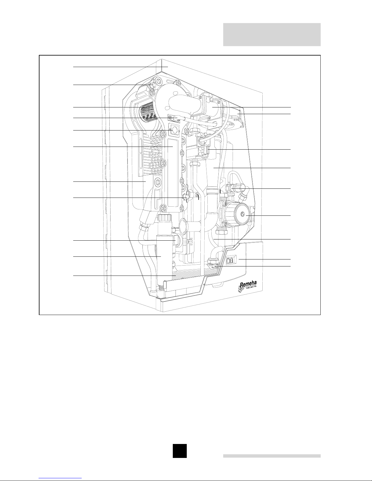
Fig. 02 Boiler layout Selecta (combi illustrated)
pdf
1. Venturi
2. Fan
3. Gas combi block
4. Air inlet tube
5. Safety valve
6. Pump
7. Expansion vessel
8. Instrument panel
9. Flow temperature sensor
(DHW; combi boiler only)
10. Plate heat exchanger
(combi boileronly)
11. Siphon / condensate outlet
12. 3-Way valve (combi boiler only)
13. Temperature sensor return
14. Heat exchanger
15. Heat exchanger inspection cover
16. Inspection glass
17. Combined ignition/ ionisation probe
18. Burner
19. Temperature sensor flow
20. Flue outlet / air inlet (60/100 mm; on
top, not visable in this picture)

9
2.2 Working principle
The Remeha Selecta’s casing serves as a sealed air box, with air drawn in by the
fan. On the outlet side of the fan is a venturi, into which a measured quantity of gas is
injected based on the volume of air available. The fan speed control is dependent on
the settings of the heat requirement and the prevailing temperatures (measured by the
temperature sensors).
The method of gas/air combination ensures that the gas quantity is precisely adjusted
to the air quantity. This creates optimum combustion over the whole heat input range.
The gas/air mixture is mixed in the venturi and then flows to the burner. After combustion, the hot flue gas is directed through a specially designed, high efficiency cast
aluminium heat exchanger with a large surface area, and transferring its heat to the
heating water. The water vapour in the flue gas condenses against the “pins” within the
heat exchanger, and the heat released during this process (the so-called latent or condensation heat) is also transferred to the heating water. The condensate water formed
is discharged via a siphon on the bottom of the heat exchanger.
NOTE: In normal operation, the boiler’s flue gas discharge will produce a visible white
condensing “plume” and care should be taken when choosing a location.
2.3 Combi boiler operation
The Remeha Selecta combi contains a facility for providing domestic hot water in addition to central heating. The opening of a hot water tap is detected by a temperature
sensor, which is located on the cold water inlet side of the heat exchanger. This sensor
then activates the motorised three-way valve to provide domestic hot water. Once the
demand for hot water stops the motorised valve automatically returns to the central
heating position. This three-way valve is electrically controlled by the control box and
only consumes power when it is changing to a different position.
2.4 Advanced boiler control (‘abc’- control)
An intelligent advanced boiler control (‘abc’) continuously monitors the boiler conditions and ensures a very reliable supply of heat. This control system is adept at dealing with negative influences from the system such as flow reduction, airflow problems
and alike. In the event of such influences, the boiler will not go into “lock-out” failure
mode, but will in the first instance modulate back. If necessary, depending on the
nature of the circumstances, it will temporarily switch off (shutdown or control stop),
and then after a short while simply try again.
NOTE: Provided that the situation is not actually hazardous, the Remeha Selecta will
always try to supply heat. The ‘abc’- control prevents unnecessary additional call outs.
Remeha Selecta
10
3 DIMENSIONS AND TECHNICAL DATA
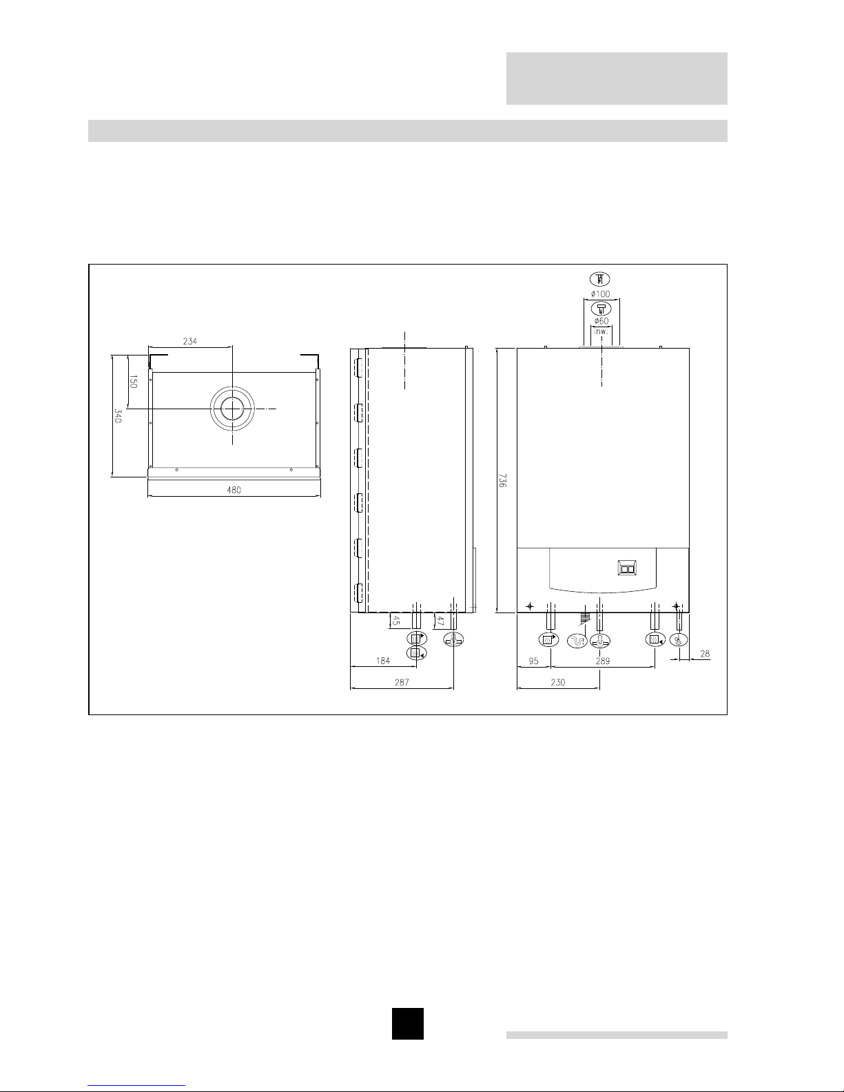
3.1 Dimensions
All dimensions of relevance to the installation of the appliance are shown in Fig. 03
and Fig. 04. For clearance details, see Fig. 05.
Fig. 03 Dimensions Selecta system
04.W5H.79.00002
Ê Return connection 22 mm Ø o/d
É Flow connection 22 mm Ø o/d
Ï Gas connection 15 mm Ø o/d
Ð Combustion air supply connection 100 mm Ø i/d
Ñ Flue gas discharge connection 60 mm Ø i/d
Ò Condensate connection 25 mm Ø
Ù Safety valve discharge 15 mm Ø
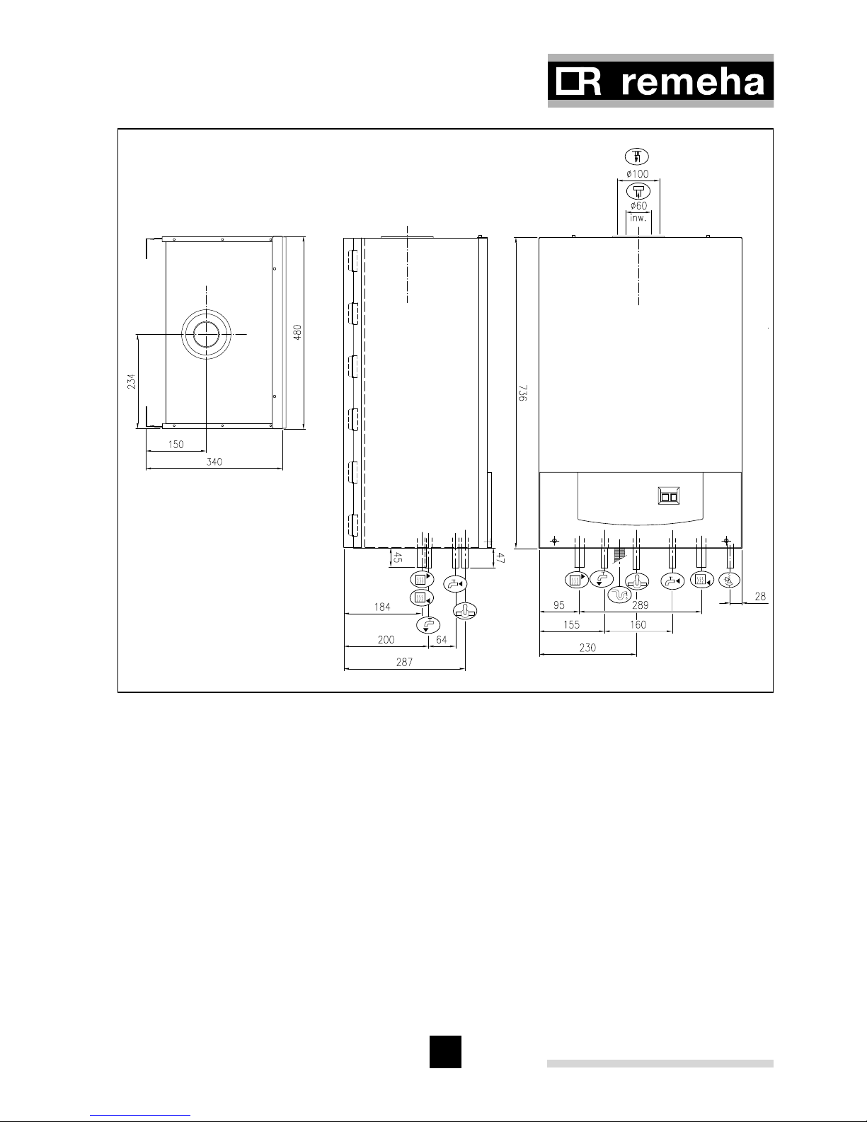
11
Fig. 04 Dimensions Selecta combi
04.W5H.79.00001
Ê Return connection 22 mm Ø o/d
É Flow connection 22 mm Ø o/d
Ï Gas connection 15 mm Ø o/d
Ð Combustion air supply connection 100 mm Ø i/d
Ñ Flue gas discharge connection 60 mm Ø i/d
Ó DHW inlet connection 15 mm Ø o/d
Ô DHW outlet connection 15 mm Ø o/d
Ò Condensate connection 25 mm Ø
Ù Safety valve discharge 15 mm Ø
Remeha Selecta
12
3.2 Technical details
Boiler type Selecta combi system
General
Boiler control Modulating
Nominal output (80/70°C) kW 5.1 - 16.0 5.1 - 16.0
Nominal output (50/30°C) kW 5.6 - 16.8 5.6 - 16.8
Maximum output DHW kW 23.89 Nominal input (CH) Hs
(GCV)
kW 5.8 - 18.3 5.8 - 18.3
Nominal input (CH) Hi
(NCV)
kW 5.2 - 16.5 5.2 - 16.5
Nominal input (DHW) Hs
(GCV)
kW 5.8 - 26.7 5.8 - 26.7*
Nominal input (DHW) Hi
(NCV)
kW 5.2 - 24.0 5.2 - 24.0*
Weight dry kg 45 42
Maximum Noise level at 1 m distance
from the boiler dB(A) <44 <44
SEDBUK rating A A
Gas- and flue details
Category II
2H3P
Min/Max Inlet pressure natural gas mbar 17 - 30
Gas consumption (CH/DHW) m
n
3
/h 0.6 - 1.7 / 2.5
NOx -emission (n = 1) ppm < 25
Residual fan duty (full load) Pa 95
Mass flue rate (CH/DHW) kg/h 26 / 39
Classification due to discharging flue
gases
C13, C33
CH- side
Water capacity
heat exchanger + piping l 2.6
High limit temperature °C 110
Operating flow temperature °C 20 - 90
Operating range bar 0.8 - 3.0
DHW - side
Maximum flow rate at 35°C dt
l/min 10 -
Minimum flow l/min < 1 Water capacity l 0.2 Inlet water pressure bar 0.16 - 8.0 -
13
Electrical
Main supply V/Hz 230 / 50
Power consumption
max.
W 130
Insulation class IP 20
Fuse rating A 3
Table 01 Technical details
* with Broag Kit No.1 and calorifier
3.3 General Specifications
(to be read with above table)
- One piece cast aluminium heat exchanger
- 22 mm Ø (m) flow and return connections
- 15 mm Ø (m) gas connection
- Maximum operating pressure of 3.0 bar
- Maximum operating temperature of 95°C
- Low NOx, < 25 ppm (O
2
= 0%)
- Pre-mix, fully modulating (25 -100%) gas burner with gas/air ratio control for maximum efficiency
- Intelligent advanced boiler control ‘abc’ c/w a comprehensive operating, service
and fault diagnostic facility
- Available for room sealed operation
- Supplied fully factory assembled
- Powder coated enamel steel casing and plastic front panel with cover
- Suitable for use with a Natural gas (standard) or propane (with optional kit)
- Efficiency of 98% at 80/60 °C (Hi)
- Max. efficiency of 109.2% (Hi) in fully condensing mode
- Manufactured to ISO 9001
- CE approved
- British Gas Approval Service listed
- Kiwa (Water regulations) approved product
- Flow temperature sensor DHW (for combi boiler only)
- 3-Way valve (for combi boiler only)
- Plate heat exchanger (for combi boiler only)

Remeha Selecta
14
3.4 Optional Accessoiries
- Kit No. 1 = 3-Way DHW diverting valve c/w wiring loom, immersion sensor and ½ “
BSP pocket (for system boiler only)
- Kit No. 2 = volt free relay for use with external mains voltage switching time clocks
(for system and combi boilers)
- Kit No. 3 = digital 7-day volt free switching time clock and harness for mounting in
the boiler (for combi boiler only)
- OpenTherm
®
fully modulating room controller = for room compensation based on
inside temperature (for combi boiler only)
- Outside sensor = for fully modulating weather compensation based on outside tem-
perature (for combi and system boilers with Kit No.1 fitted)
- Propane kit = conversion from natural gas to propane (for system and combi boil-
ers)
- Pipework cover plate = metal casing cover panel to hide bottom pipe connections
(for system and combi boilers)
- Mounting frame = allows first fixing of pipework without mounting the boiler (for sys-
tem and combi boilers)
- Cleaning tool = tool to clean the boiler heat exchanger (for system and combi
boilers)
- McAlpine condensate connector = allows connection from flexible condense pipe to
std overflow pipe (for system and combi boilers)
NOTE: Room controller and outside sensor cannot be used together.
15
4 INSTALLATION INSTRUCTIONS
The installation, commissioning and servicing of the boiler must be carried out by a
competent person who holds valid ACS certification and to be a member of CORGI.
All electrical work must be carried out by a competent person and to be installed in
accordance with the current IEE regulations.
4.1 General
Care should be taken when unpacking the boiler.
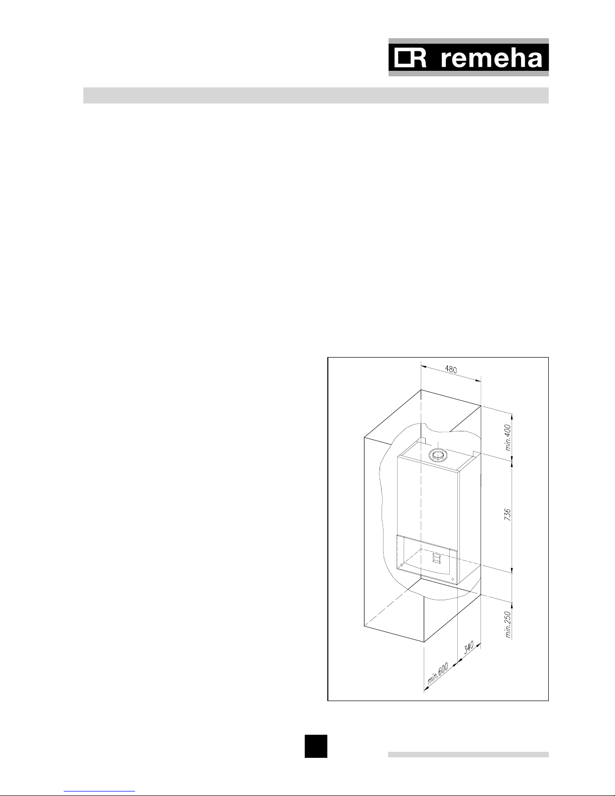
4.2 Boiler positioning
The boiler should be mounted in a room which, even during severe cold weather,
remains frost-free (see Par. 7.2.5 for more information). The boiler should be mounted
on a suitable vertical wall which is able to support the weight of the boiler.
If the boiler is to be installed in a timber framed building, please refer to British Gas
publication: ‘Guide for Gas Installations in Timber frame Housing’, reference DM2.
Fig. 05 Clearance requirements
04.W5H.79.00004
4.3 Boiler mounting
The boiler can be mounted in two ways:
1. using the wall bracket supplied with
the boiler,
2. using the mounting frame (optional)
supplied in a seperate box.
4.3.1 Clearance requirements
The gas and water connections are
located on the bottom of the boiler.
Whether the standard wall bracket or
the mounting frame is used, there is
adequate space to run the pipes behind
the boiler if required. All components are
accessible from the front of the boiler.
However, we do recommend a minimum
side clearance of 2.5 cm so that the unit
is easy to open. A free space of 25 cm
under the appliance and 40 cm above
the appliance, see Fig. 05, should be
regarded as the minimum requirement.
Remeha Selecta
16
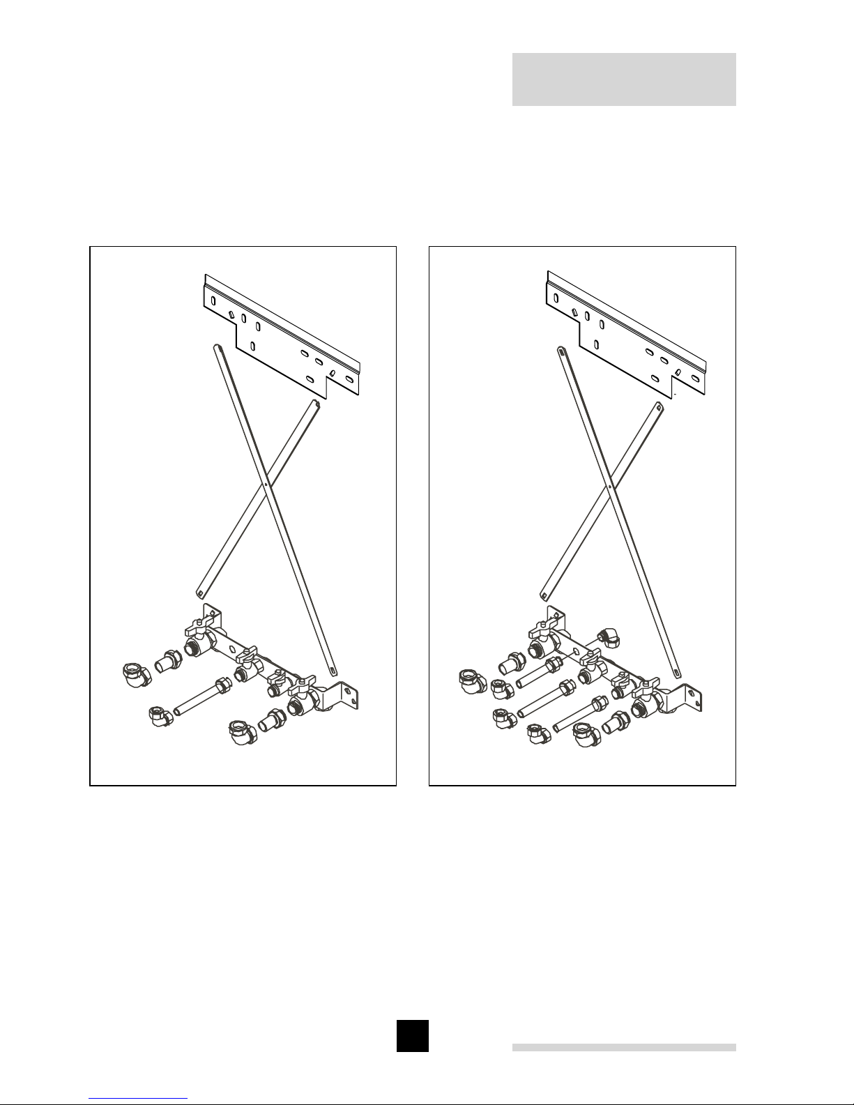
4.3.2 Mounting frame
Suitable for most applications as a two-stage installation. The frame, see Fig. 06 and
Fig. 07 can be installed complete with all supply pipework to allow the system to be
filled and tested. The boiler can then be fitted at a later date. Instructions for installing
the mounting frame are supplied with it.
Fig. 06 Mounting frame system boiler
eps
Fig. 07 Mounting frame combi boiler
eps
17
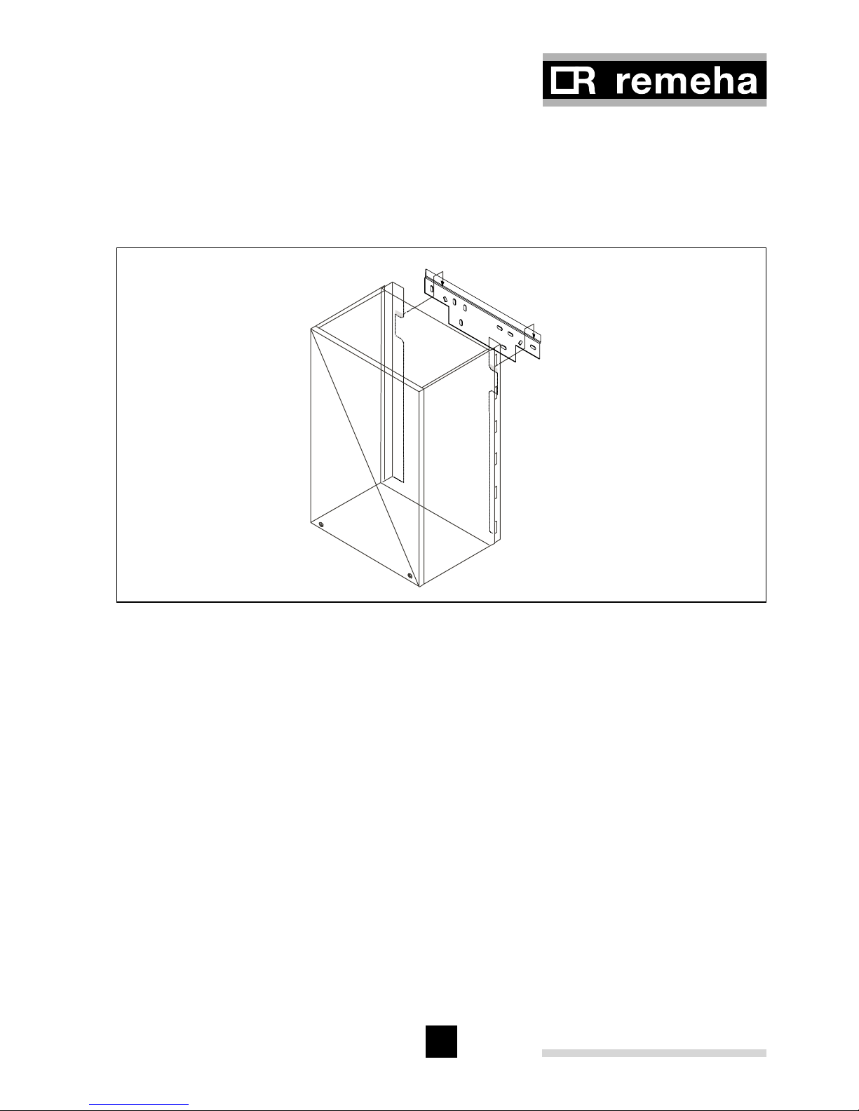
4.3.3 Wall bracket
Using the template provided mark fixing holes and flue outlet centre on the wall. Drill
the wall, using the plugs and screws provided and secure the mounting bracket to the
wall. Carefully lift boiler and locate the cut out in the back onto the wall bracket, see
Fig. 08.
Fig. 08 Wall bracket
eps wall bracket
Note: It is possible to route pipework behind the boiler using this option.
Fixings supplied are suitable for brick/block wall only and alternative fixings
should be used on different wall types.
4.4 Flue gas discharge and air supply
The Remeha Selecta is only suitable for room sealed operation with a concentric horizontal or vertical flue. After mounting boiler and before connecting the flue assembly,
remove the dust cap from flue/air inlet connection.
Compartment ventilation is not required with this boiler with the concentric flue system.
Attention: plastic flues should not be used!
Remeha Selecta
18
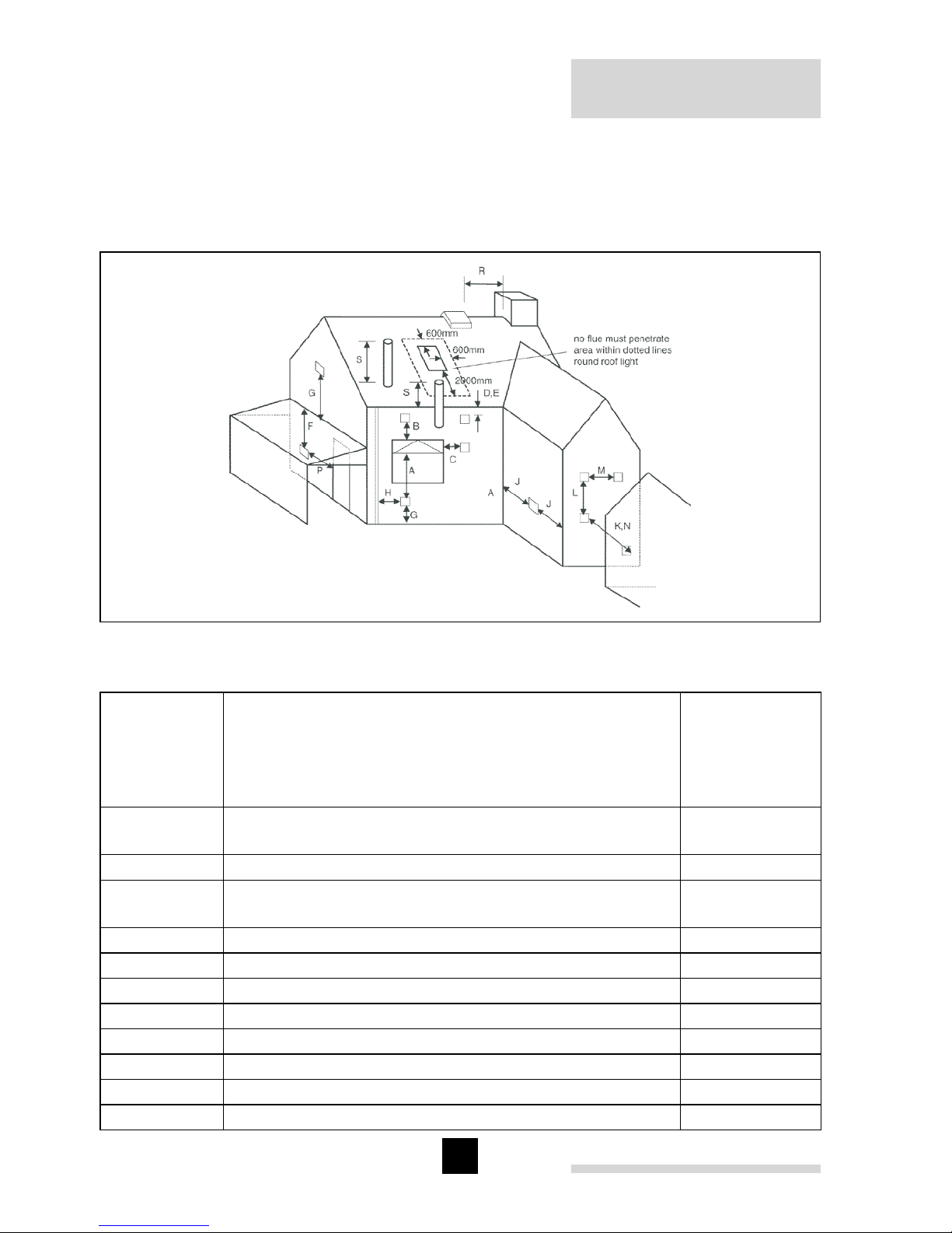
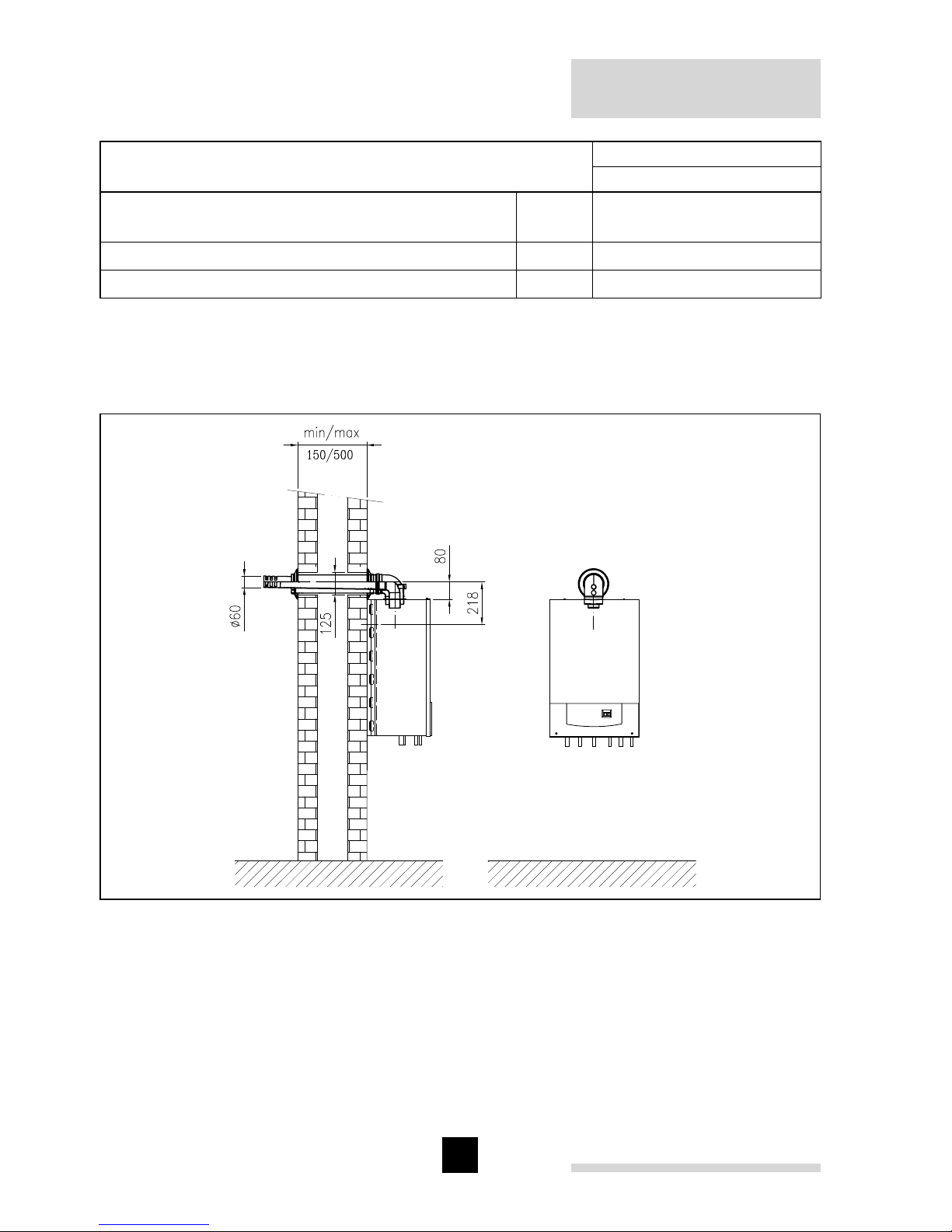
4.4.1 Flue terminal positions
The flue terminal positions for the Remeha Selecta are shown in Fig. 09. The minimum
distances to the terminal can be found
in Table 02.
Fig. 09 Flue terminal positions
pdf
Dimensions Terminal location
Minimum
distance
(in mm) to
terminal
(room sealed)
A
Directly below an opening, air brick,
opening window, etc.
300
B Above an opening, air brick, opening window, etc. 300
C
Horizontally to an opening, air brick,
opening window, etc.
300
D Below a gutter or sanitary pipe work 75
1)
E Below the eaves 200
F Below a balcony or carport roof 600
G Above ground, roof or balcony level 300
H From vertical drain/soil pipe work 75
1)
J From an internal or extarnal corner 30
K From a surface or boundary facing the terminal 600
2)
L Vertically from a terminal on same wall 1500
19
M Horizontally from a terminal on same wall 300
N From a terminal facing the terminal 1200
P
From an opening in a carport (e.g. door, window) into
the building
1200
R From a vertical structure on the roof n/app
S Above an intersection with the roof n/app
Table 02 Minimum distances to terminal
1)
= Notwithstanding the dimensions above, a terminal serving a natural draught and
fanned draught appliance more than 5kW heat input should be at least 300 mm
and 150 mm respectively from combustible material.
2)
= The distance from a fanned draught appliance terminal installed at right angles to
a boundary may be reduced to 300 mm in accordance with Fig. 09.
n/app = not applicable.
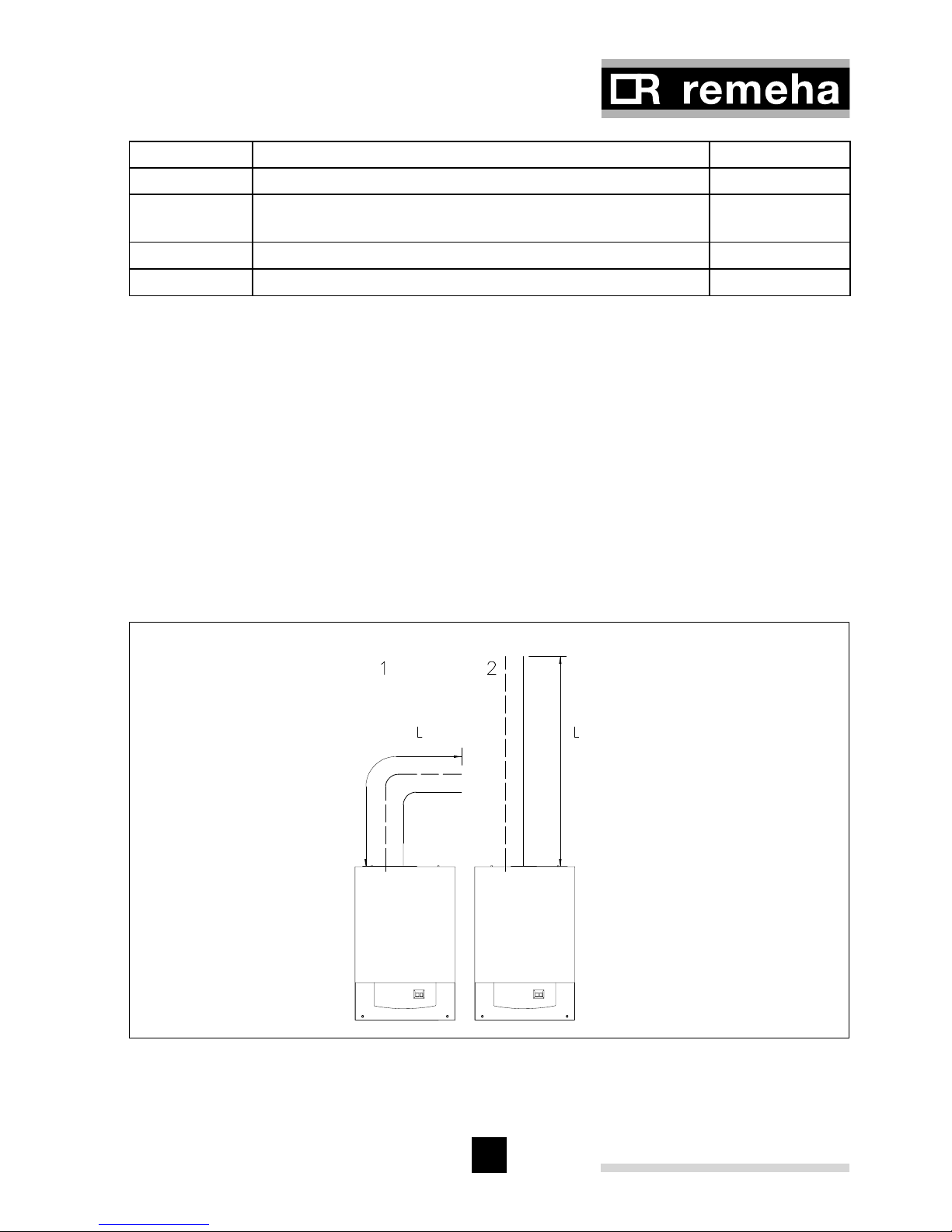
4.5 Type of arrangement in connection with flue gas discharge
Arrangement according to CE: type C13, C33.
4.5.1 Single boiler, concentric room sealed flue
Fig. 10 Flue gas discharge duct, single boiler, room sealed application
04.W5H.79.00005
Remeha Selecta
20
Ø D (mm)
Ø 60/100
Max. length horizontal including bend ‘L’
Max. length vertical with no bends ‘L’
m
m
7*
9*
Deduct per extra bend 90° m 2
Deduct per extra bend 45° m 1
Table 03 Permissible flue gas discharge lengths with closed systems
* Note: For lengths in excess of this, the 80/125 system can be used with a suitable
adaptor. Please contact Broag for the required details.
Fig. 11 Remeha Selecta with concentric horizontal flue
04.W5H.79.00011
21
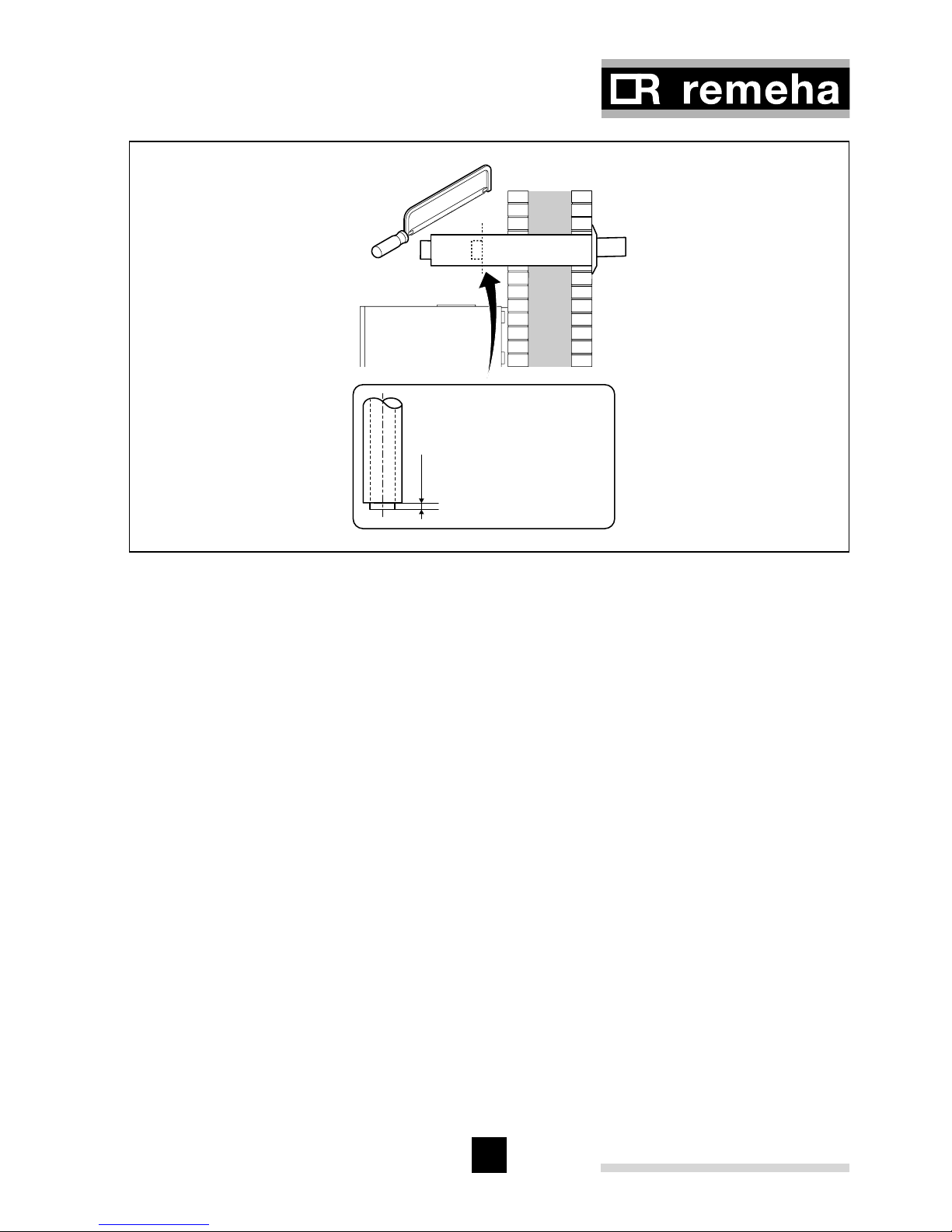
20 mm
When shortening, pay attention
to the 20 mm difference.
Fig. 12 Flue cutting instruction
pdf
* Detailed instructions for measuring and cutting flue are included with our horizontal
flue kit.
4.6 Installation data
4.6.1 Condensate drain
The condensate drain from the boiler must be connected to a suitable wastewater
drainage point, preferably within the building. The connecting pipe and fittings must
be made of plastic material only. After assembly, fill the siphon with water. The slope
of the drain pipe should be at least 30 mm/m. If pipe runs are made external to the
building they should always be insulated.

Remeha Selecta
22
4.6.2 Water treatment
Where system water treatment is required or specified (eg inhibitors), it must be compatible for use with an aluminium heat exchanger.
If water treatment is used we recommend only the following products which must be
used in accordance with the manufacturers instructions:
‘Copal
’ manufactured by: or: Sentinal ‘X100’ manufactured by:
Fernox, Cookson Electronics BetzDearborn Ltd
Forsyth Road Sentinal
Sheerwater Foundry Lane
Woking Widnes
Surrey GU21 5RZ Cheshire WA8 8UD
Tel No: 01483 793200 Tel No: 0151 424 5351
Fax No: 01483 793201 Fax No: 0151 420 5447
Email: sales@fernox.com
Web site: www.fernox.com
For the correct dosage and for further information on water treatment or system cleaning we advise direct contact with either of the above companies.
Note: Scale deposits in excess of 5 mm will reduce boiler efficiency and increase the
risk of premature casting failure.
4.6.3 Safety valve discharge
A safety valve is fitted in the boiler and is set as standard to 3 bar.
If the pressure in the boiler becomes too high the pressure is relived by releasing
water outside via the safety valve discharge pipe. The safety valve discharge pipe
must be at least 15 mm Ø. The discharge should be terminated facing downwards
exterior to the building in a position where discharging water will not create danger or
nuisance but remains in a visible position.
4.6.4 Expansion vessel
An 8 ltre expansion vessel (with the vessel charge set to 0.5 bar) is fitted as standard
within the boiler case and is suitable for use in a heating system with a water content
up to 100 litres, operating at a flow temperature of 80°C, a maximum pressure of 3 bar
and a maximum system static head of 5M above the boiler. If the system water content
is greater than 100 litres, or the system static head above the boiler is greater than
5M, an additional vessel must be installed in the system to allow for the increase in
expansion, see Table 04.
 Loading...