


rematic® 2945 C3 K
Fitting Instructions for
Gas 210 Boiler Kit
R e m e h a Gas 210 ECO
ISSUE 2 - 21/11/01
IMPORTANT NOTE
The boiler must be electrically disconnected before any work is carried out.
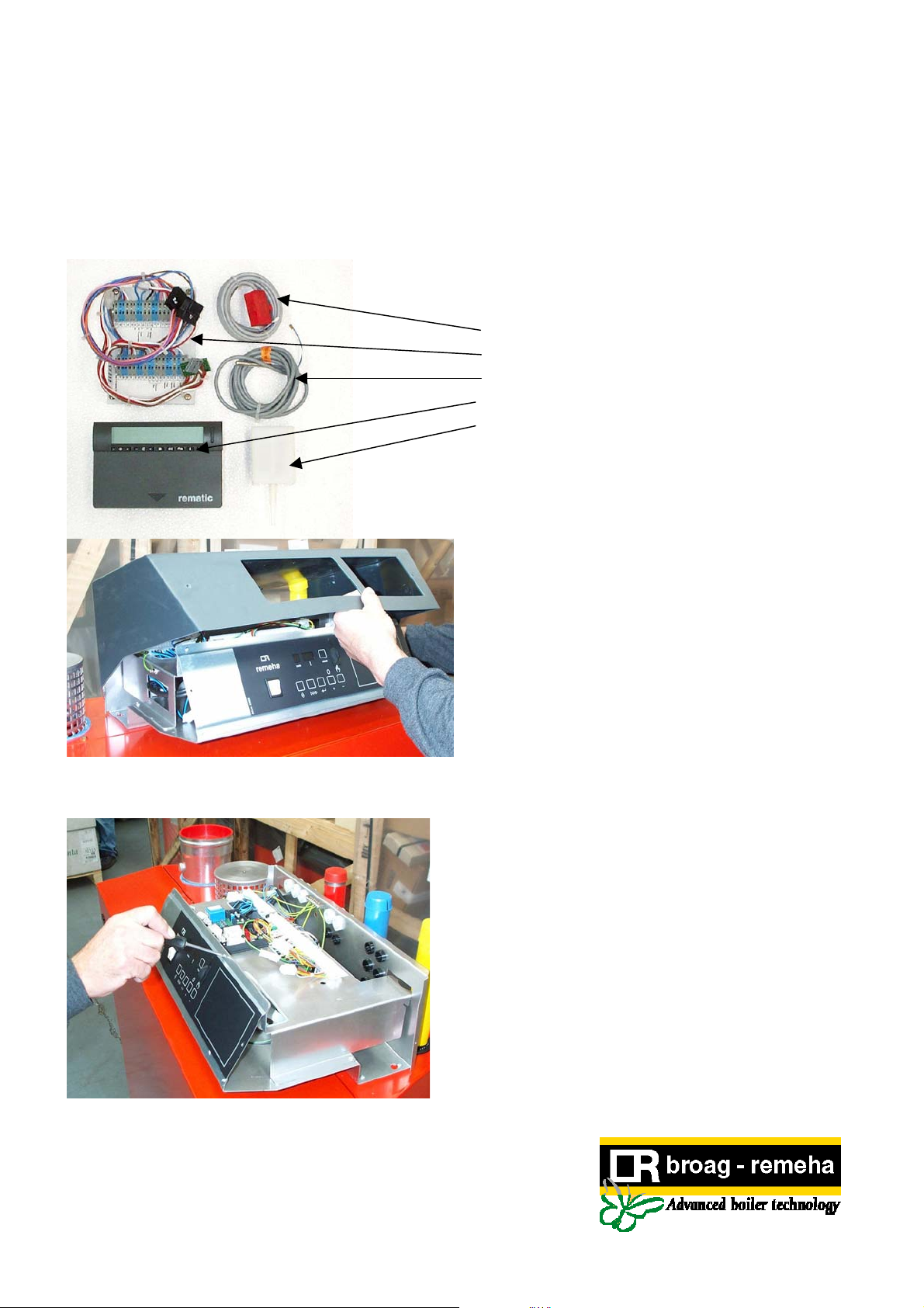
Kit Components
1. Flow sensor (strap on)
2. Adaptor plate with harness
3. DHW sensor
4. 2945 C3 K
5. Outside sensor
6. Instructions
(Part No. 55795)
rematic
® Control
Release the 4 control panel cover screws and
remove the cover
Release the front panel screws
.
ISSUE 2 - 21/11/01
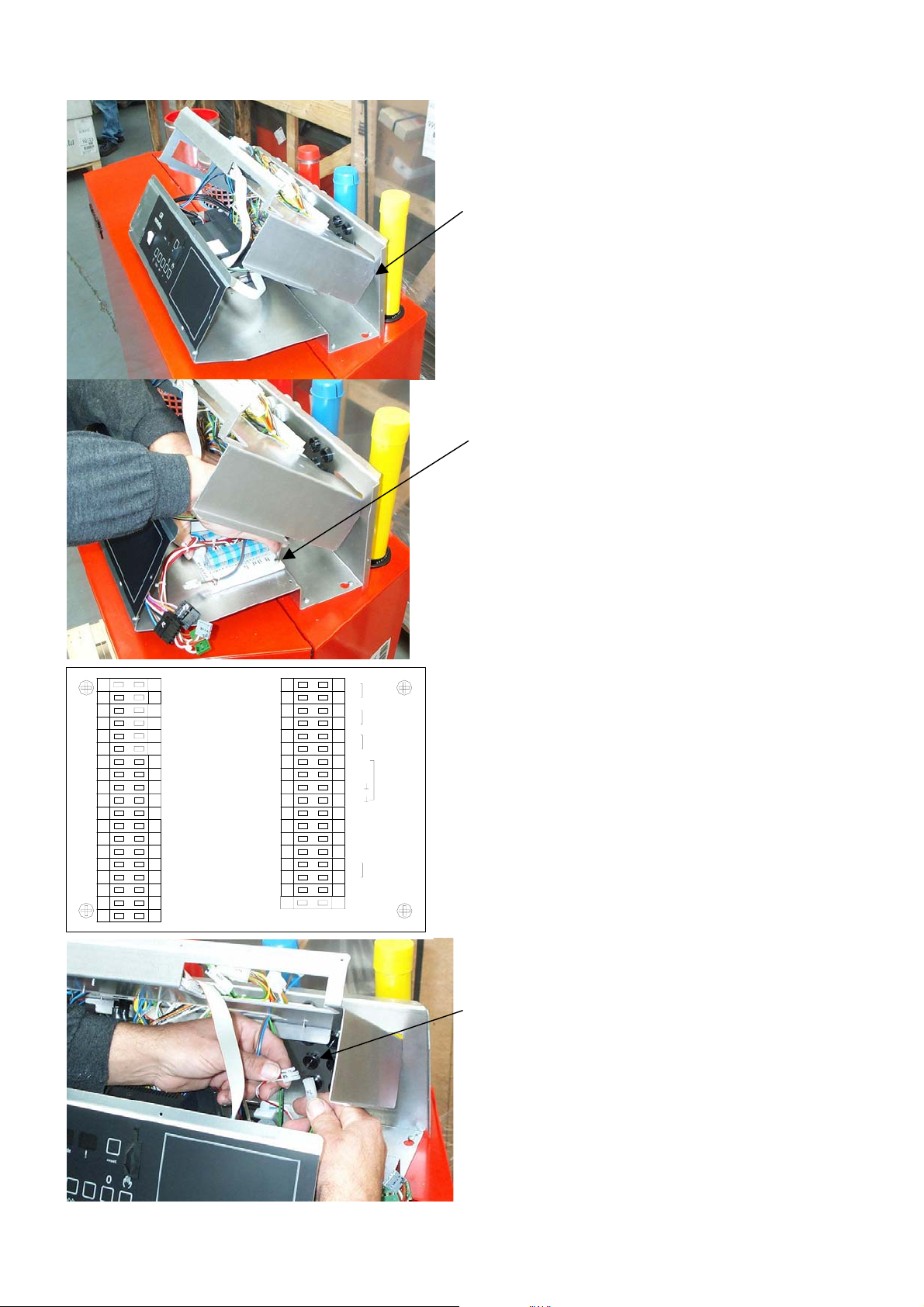
Raise and tilt the terminal strip assembly locking it
onto the slots on the rear support as shown in
picture
Fit the adapter plate onto the lower assembly using
the 4 screws supplied
1
2
3
4
5
6
7
8
N
9
System Pump
L
10
11
L
DHW Pump/Valve
12
N
N
13
14
15
16
17
18
19
Gas 210 Series Only
20
21
Outside Sensor
22
DHW Sensor *
23
24
Flow Sensor #
25
+
26
+
27
28
29
30
31
32
33
Internal room
34
sensor ##
35
36
37
n
o
i
s
Bu
Communicat
Mount the outside sensor in a sheltered position on
a north facing wall - wire back to boiler (max 100M)
Fit flow sensor (only required for multiple boilers)
on the common flow pipework
Fit DHW sensor into calorifier if DHW is being
controlled by the the rematic® 2945 C3 K control
unit
Connect sensors onto the adapter plate as detailed
in the accompanying instructions
Note: sensor cables must be screened if run with
power cables (ensure screen is earthed)
Find plugs K1 and K2 in the control panel wiring
and fit the matching K1 and K2 plugs on the
adapter plate harness
3
 Loading...